

Page 1
TEC Two -Color Printer
Table of Contents
CB-426-T3-QQ
Owner’s Manual
Page 2

W e, TOSHIBA TEC Corporation of 570 Ohito Ohito-cho T agata-Gun Shizuoka-Ken 410-2323 JAP AN,
declare in our sole responsibility that this product has been tested and found to comply with the limits
for a Class A digital device, pursuant to Part 15 of the FCC Rules. These limits are designed to
provide reasonable protection against harmful interference when the equipment is operated in a
commercial environment. This accordance with the instruction manual, may cause harmful interference
to radio communications. Operations of this equipment in a residential area is likely to cause harmful
interference in which case the user will be required to correct the interference at his own expense.
(for USA only)
Changes or modifications not expressly approved by manufacturer for compliance could void the
user’s authority to operate the equipment.
“This Class A digital apparatus meets all requirements of the Canadian Interference-Causing Equipment
Regulations.”
“Cet appareil numérique de la classe A respecte toutes les exigences du Règlement sur le matériel
brouilleur du Canada.” (for CANADA only)
CAUTION:
1.This manual may not be copied in whole or in part without prior written permission of TOSHIBA
TEC.
2.The contents of this manual may be changed without notification.
3.Please refer to your local Authorized Service representative with regard to any queries you may
have in this manual.
Trademark:
• Microsoft, Windows, Windows NT, and the Windows Logo are either registered trademarks or
trademarks of Microsoft Corporation in the United States.
• All other brands and names are the property of their respective owners.
Copyright © 2000
by TOSHIBA TEC CORPORATION
All Rights Reserved
570 Ohito, Ohito-cho, Tagata-gun, Shizuoka-ken, JAPAN
Page 3
Safety Precautions
Safety Precautions
Safety Summary
Meanings of Symbols
Personal safety in handling or maintaining the equipment is extremely
important. Warnings and Cautions necessary for safe handling are
included in this manual. All warnings and cautions contained in this
manual should be read and understood before handling or maintaining
the equipment.
Do not attempt to effect repairs or modifications to this equipment.
If a fault occurs that cannot be rectified using the procedures described
in this manual, turn off the power, unplug the machine, then contact
your authorized TOSHIBA TEC representative for assistance.
This symbol indicates warning items (including cautions).
Specific warning contents are drawn inside the symbol.
(The symbol on the left indicates a general caution.)
This symbol indicates prohibited actions (prohibited items).
Specific prohibited contents are drawn inside or near the
(The symbol on the left indicates “no disassembling”.)
This symbol indicates actions which must be performed.
Specific instructions are drawn inside or near the symbol.
(The symbol on the left indicates “disconnect the power cord plug
from the outlet”.)
symbol.
i
Page 4
Safety Precautions
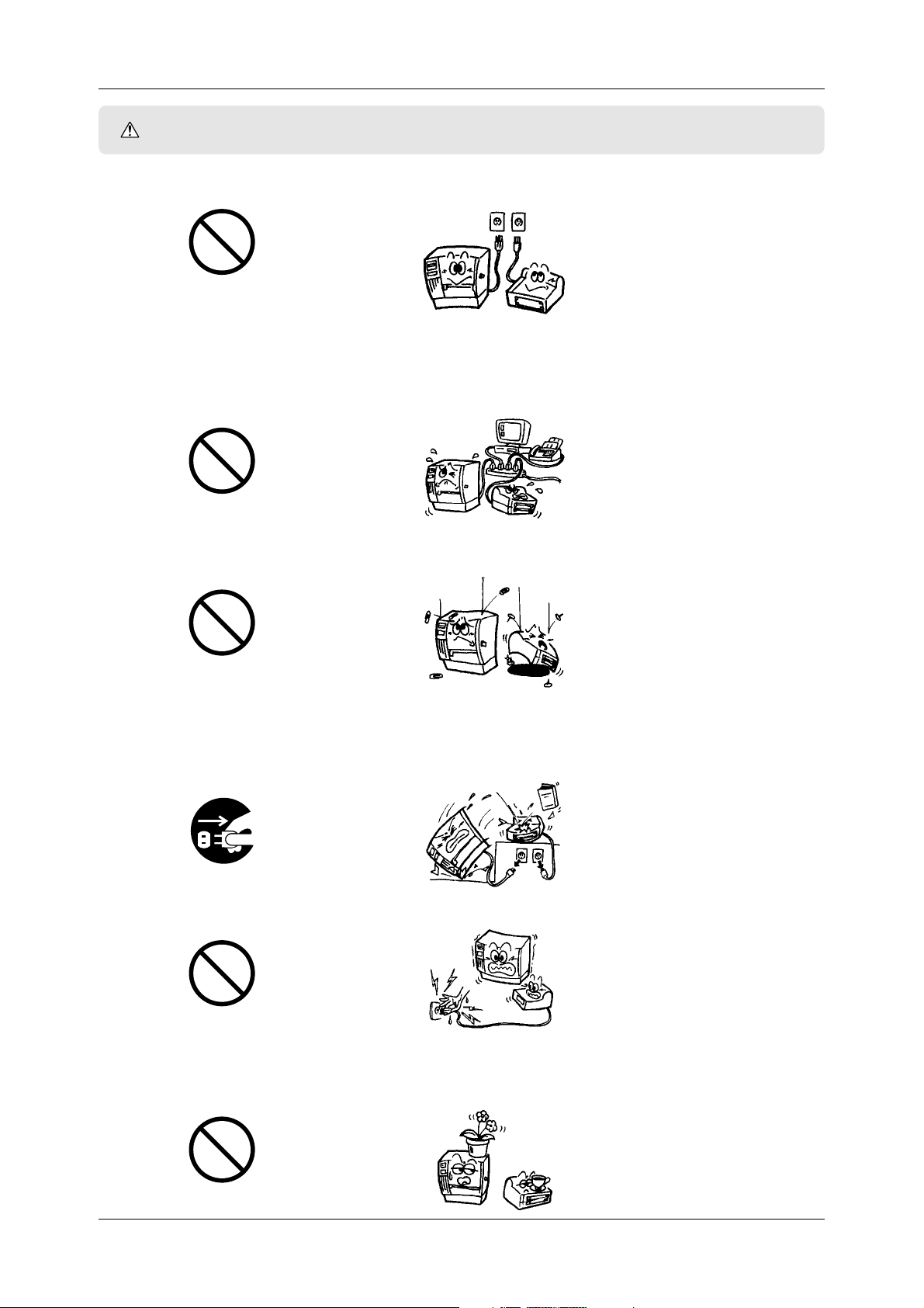
WARNING
Any other than the specified AC voltage
is prohibited.
Prohibited
This indicates that there is the risk of death or serious injury if the
machines are improperly handled contrary to this indication.
■ Do not use voltages other than the voltage (AC) specified on the
rating plate, as this may cause fire or electric shock.
■ If the machines share the same outlet with any other electrical
appliances which consume large amounts of power, the voltage
will fluctuate widely each time these appliances operate. Be sure
to provide an exclusive outlet for the machine as this may cause
the machines to malfunction.
■ Do not insert or drop metal, flammable or other foreign objects
into the machines through the ventilation slits, as this may cause
fire or electric shock.
Prohibited
Disconnect the plug.
Prohibited
■ If the machines are dropped or their cabinets damaged, first turn
off the power switches and disconnect the power cord plugs from
the outlet, and then contact your authorized TOSHIBA TEC
representative for assistance. Continued use of the machine in
that condition may cause fire or electric shock.
■ Do not plug in or unplug the power cord plug with wet hands as
this may cause electric shock.
■ Do not place metal objects or water-filled containers such as flower
vases, flower pots or mugs, etc. on top of the machines. If metal
objects or spilled liquid enter the machines, this may cause fire or
electric shock.
Prohibited
ii
Page 5
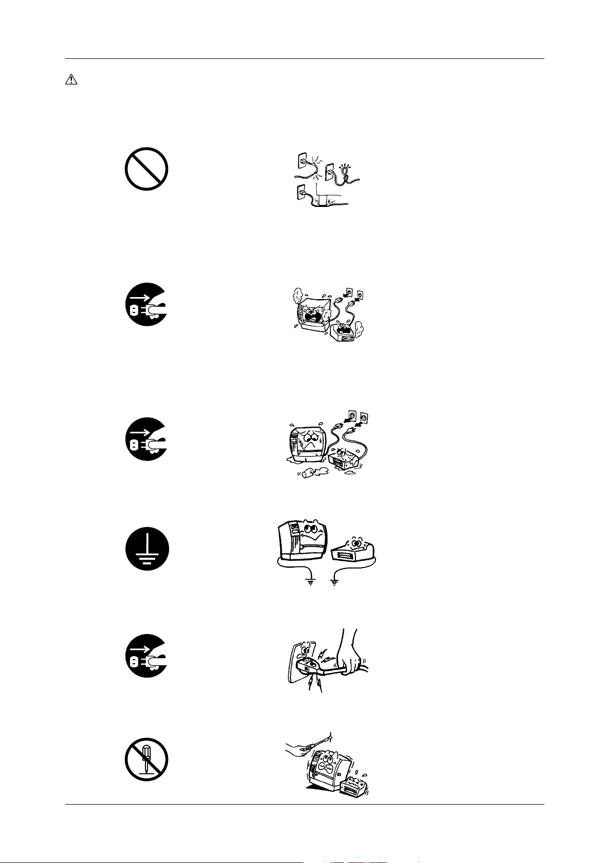
WARNING (Cont.)
Prohibited
Disconnect the plug.
Safety Precautions
■ Do not cut, damage or modify the power cords. Also, do not
place heavy objects on, pull on, or excessively bend the cords, as
this may cause fire or electrical shock.
■ Continued use of the machines in an abnormal condition such as
when the machines are producing smoke or strange smells may
cause fire or electric shock. In these cases, immediately turn off
the power switches and disconnect the power cord plugs from the
outlet. Then, contact your authorized TOSHIBA TEC representative
for assistance.
■ If foreign objects (metal fragments, water, liquids) enter the
machines, first turn off the power switches and disconnect the
power cord plugs from the outlet, and then contact your authorized
TOSHIBA TEC representative for assistance. Continued use of
the machine in that condition may cause fire or electric shock.
Disconnect the plug.
Connect a grounding wire.
Disconnect the plug.
■ Ensure that the equipment is properly grounded. Extension cables
should also be grounded. Fire or electric shock could occur on
improperly grounded equipment.
■ When unplugging the power cords, be sure to hold and pull on
the plug portion. Pulling on the cord portion may cut or expose
the internal wires and cause fire or electric shock.
■ Do not remove covers, repair or modify the machine by yourself.
Y ou may be injured by high voltage, very hot parts or sharp edges
inside the machine.
No disassembling.
iii
Page 6

CAUTION
Safety Precautions
This indicates that there is the risk of personal injury or damage to
objects if the machine is improperly handled contrary to this
indication.
The following precautions will help to ensure that this machine will
continue to function correctly.
• Try to avoid locations that have the following adverse conditions:
* Temperatures out of the specification
* Direct sunlight * High humidity
* Shared power source * Excessive vibration
* Dust/Gas
• The cover should be cleaned by wiping with a dry cloth or a cloth
slightly dampened with a mild detergent solution. NEVER USE
THINNER OR ANY OTHER VOLATILE SOLVENT on the
plastic covers.
• USE ONLY TOSHIBA TEC SPECIFIED paper and ribbons.
• DO NOT STORE the paper or ribbons where they might be exposed
to direct sunlight, high temperatures, high humidity, dust, or gas.
• Ensure the printer is operated on a level surface.
• Any data stored in the memory of the printer could be lost during
a printer fault.
• Try to avoid using this equipment on the same power source as
high voltage equipment or equipment likely to cause electrical
interference.
• Unplug the machine whenever cleaning or working inside it.
• Keep the work environment static free.
• Do not place heavy objects on top of the machines, as these items
may become unbalanced and fall causing injury.
• Do not block the ventilation slits of the machines, as this will
cause heat to build up inside the machines and may cause fire.
• Do not lean against the machine. It may fall and cause injury.
• Care must be taken not to injure yourself with the printer paper cutter.
• Unplug the machine when it is not used for a long period of time.
iv
Request Regarding
Maintenance
• Utilize our maintenance services.
After purchasing the machine, contact your authorized TOSHIBA
TEC representative for assistance once a year to have the inside
of the machine cleaned. Otherwise, dust will build up inside the
machines and may cause a fire or a malfunction. Cleaning is
particularly effective before humid rainy seasons.
• Our preventive maintenance service performs the periodic checks
and other work required to maintain the quality and performance
of the machines, preventing accidents beforehand.
For details, please consult your authorized TOSHIBA TEC
representative for assistance.
• Do not expose the machines to insecticides or other volatile
solvents. This will cause the cabinet or other parts to deteriorate
or cause the paint to peel.
Page 7

Table of Contents
TOC 2
Contents
Table of Contents
1. Product Overview ................................................................................................................................................... 1
1.1 Introduction ...................................................................................................................................................... 1
1.2 Features ............................................................................................................................................................ 1
1.3 Unpacking ........................................................................................................................................................ 1
1.4 Accessories and Options ................................................................................................................................. 2
1.4.1 Accessories ............................................................................................................................................. 2
1.4.2 Cool Release Enhancement Kit ............................................................................................................... 3
1.4.3 Options .................................................................................................................................................... 3
1.5 Appearance ...................................................................................................................................................... 4
1.5.1 Dimensions .............................................................................................................................................. 4
1.5.2 Front View ............................................................................................................................................... 4
1.5.3 Rear View ................................................................................................................................................ 4
1.5.4 Operation Panel ...................................................................................................................................... 5
1.5.5 Interior ..................................................................................................................................................... 5
2. Printer Installation .................................................................................................................................................. 6
2.1 Installing the Accessories ................................................................................................................................. 6
2.1.1 Fan Filters ................................................................................................................................................ 6
2.1.2 Media Slide ............................................................................................................................................. 6
2.1.3 Supply Shaft Holder ................................................................................................................................ 6
2.2 Connecting the Printer to Your Computer ........................................................................................................ 7
2.3 Connecting the Power Cord ............................................................................................................................. 8
2.4 Turning on/off the Printer.................................................................................................................................. 9
2.4.1 Turning on the Printer .............................................................................................................................. 9
2.4.2 Turning off the Printer ............................................................................................................................ 10
2.5 Loading the Media .......................................................................................................................................... 11
2.5.1 Additional Information ........................................................................................................................... 16
2.6 Sensor Adjustments ....................................................................................................................................... 17
2.6.1 Black Mark Sensor ................................................................................................................................ 17
2.6.2 Feed Gap Sensor .................................................................................................................................. 18
2.6.3 Media Sensor Sensitivity Adjustment ................................................................................................... 19
2.7 Loading the Ribbons (for Hot Release Ribbons) ............................................................................................ 21
2.7.1 Ribbon Positions ................................................................................................................................... 21
2.7.2 Loading Procedure ................................................................................................................................ 21
2.8 Loading the Ribbons (for Cold Release Ribbons) .......................................................................................... 24
2.8.1 Precautions ........................................................................................................................................... 24
2.8.2 Installing the Ribbon Plate .................................................................................................................... 25
2.8.3 Installing the SP Ribbon Guides ........................................................................................................... 26
2.8.4 Installing the Ribbon Tension Sheet ...................................................................................................... 27
2.8.5 Loading the Cold Release Ribbons....................................................................................................... 28
3. Printing .................................................................................................................................................................. 29
3.1 Installing the Printer Driver ............................................................................................................................. 29
3.1.1 System Requirements ........................................................................................................................... 29
3.1.2 Installation Procedure (For Windows
3.1.3 Uninstalling the Printer Driver................................................................................................................ 35
3.2 Properties ....................................................................................................................................................... 37
3.2.1 Displaying Printer Properties ................................................................................................................. 37
3.2.2 Summary of Properties ......................................................................................................................... 38
3.3 Page Setup ..................................................................................................................................................... 39
3.3.1 Selecting a label size ............................................................................................................................. 39
3.3.2 Creating a new label size ...................................................................................................................... 40
3.3.3 Orientation ............................................................................................................................................. 41
3.3.4 Miscellaneous ....................................................................................................................................... 42
3.4 Graphics ......................................................................................................................................................... 46
3.4.1 Dithering ................................................................................................................................................ 46
3.4.2 Color ...................................................................................................................................................... 46
3.4.3 Color Setup ........................................................................................................................................... 47
3.4.4 Color Registration ................................................................................................................................. 50
3.5 Bar Fonts ........................................................................................................................................................ 52
3.5.1 Specifying a New Font Style ................................................................................................................. 53
3.6 Stock .............................................................................................................................................................. 55
3.6.1 Print Method.......................................................................................................................................... 55
®
98) .............................................................................................. 29
v
Page 8

Table of Contents
TOC 1
3.6.2 Sensor ................................................................................................................................................... 55
3.6.3 Label Gap .............................................................................................................................................. 55
3.6.4 Issue Settings ........................................................................................................................................ 56
3.6.5 Fine Adjustment .................................................................................................................................... 57
3.7 Options ........................................................................................................................................................... 58
3.7.1 Transfer Mode ....................................................................................................................................... 58
3.7.2 Print Density Adjustment....................................................................................................................... 58
3.8 Testing ............................................................................................................................................................ 59
3.8.1 Testing ................................................................................................................................................... 59
3.8.2 Maintenance .......................................................................................................................................... 60
3.9 Print Test ......................................................................................................................................................... 61
3.9.1 Procedures ............................................................................................................................................ 61
3.10 Printing a Label .............................................................................................................................................. 62
4. Online Mode .......................................................................................................................................................... 64
4.1 Operation Panel.............................................................................................................................................. 64
4.2 Operation........................................................................................................................................................ 65
4.3 Reset .............................................................................................................................................................. 65
5. Maintenance ......................................................................................................................................................... 66
5.1 Cleaning ......................................................................................................................................................... 66
5.1.1 Print Head/Platen .................................................................................................................................. 66
5.1.2 Pinch Roller/Feed Roller/Media Guide .................................................................................................. 67
5.1.3 Fan Filters .............................................................................................................................................. 67
5.1.4 Covers and Panels ................................................................................................................................ 68
5.1.5 Ribbon Modules .................................................................................................................................... 68
6. Troubleshooting.................................................................................................................................................... 69
6.1 Error Messages .............................................................................................................................................. 69
6.2 Possible Problems.......................................................................................................................................... 71
6.3 Removing Jammed Media ............................................................................................................................. 72
6.3.1 From the Pinch Roller Unit .................................................................................................................... 72
6.3.2 From the Print Head Block .................................................................................................................... 72
6.4 When the Ribbon is Torn Apart ...................................................................................................................... 73
Appendix 1 Specifications......................................................................................................................................... 74
A1.1 Printer ............................................................................................................................................................. 74
A1.2 Options ........................................................................................................................................................... 75
A1.3 Media.............................................................................................................................................................. 75
A1.3.1 Media Type ............................................................................................................................................ 75
A1.3.2 Detection Area of the Transmissive Sensor .......................................................................................... 76
A1.3.3 Detection Area of the Reflective Sensor ............................................................................................... 77
A1.3.4 Effective Print Area................................................................................................................................ 77
A1.4 Ribbon ............................................................................................................................................................ 78
Appendix 2 DIP Switches .......................................................................................................................................... 79
A2.1 DIP Switch A .................................................................................................................................................. 80
A2.2 DIP Switch B .................................................................................................................................................. 81
A2.3 Ribbon Near End Detection ........................................................................................................................... 82
Appendix 3 Quick Reference for Printing ................................................................................................................ 83
Appendix 4 Message and LED .................................................................................................................................. 86
Appendix 5 System Mode.......................................................................................................................................... 88
A5.1 Operation Panel.............................................................................................................................................. 88
A5.2 Overview......................................................................................................................................................... 89
A5.3 Self-Diagnostic Test ....................................................................................................................................... 91
A5.4 Parameter Setting .......................................................................................................................................... 92
A5.5 Test Print ....................................................................................................................................................... 101
A5.6 RAM Clear .................................................................................................................................................... 104
A5.7 Additional Information .................................................................................................................................. 106
A5.7.1 Self-Diagnostic Test Result Sample and Descriptions ........................................................................ 106
A5.7.2 Maintenance Counter/Parameter Check Print Sample and Descriptions........................................... 107
A5.7.3 Cut Operation Example ....................................................................................................................... 108
A5.7.4 Pulse Motor Speed ............................................................................................................................. 108
A5.7.5 X-Coordinate Fine Adjustment ............................................................................................................ 108
A5.7.6 Magnified Views of Slant Line Pattern ................................................................................................ 108
A5.7.7 Initial Values after Clearing the Maintenance Counter (MAINTE.CNT.CLEAR).................................... 109
A5.7.8 Initial Values after Clearing the Parameter (PARAMETER CLEAR)...................................................... 110
A5.7.9 Initial Values after Clearing the Print Distance (PRINT STEP CLEAR)................................................. 111
Appendix 6 Interface................................................................................................................................................ 112
vi
Page 9

1. Product Overview
Chapter 1 Product Overview
1.1 Introduction
1.2 Features
Thank you for choosing the TOSHIBA TEC CB-426-T3 two-color
printer.
This Owner’s Manual describes printer setup and installation
procedures, printer properties, settings and adjustments, and
maintenance information. Thus it should be read carefully to help
gain maximum performance and life from the printer. For further
information please refer to this manual and keep it safe for future
reference.
The CB-426-T3 two-color printer has the following features:
• H igh-speed, quality printing. The printer utilizes Edge Heads that
support the high-performance Hot Release Ribbons to produce a
maximum print speed of approximately 6 in/s (150 mm/s). In addition,
the Cool Release Enhancement Kit is supplied as an accessory, and
allows the popular Cold Release Ribbons to be loaded.
• Fine, sharp color printing. The printer utilizes two high-resolution
(305 dpi) print heads, and uses a variety of spot color ribbons for
solid printing.
• A variety of printer fonts and bar code fonts are built into the
printer to help create a unique colored label.
• Cost efficiency. The automatic ribbon saver is standard and allows
for conservation of individual ribbons. In addition, the media
back feed capability allows you to avoid wasting the media.
1.3 Unpacking
Unpack the printer as per the Unpacking Instructions packed with
the printer.
Important!
• Check for damage or scratches on the printer.
However, please note that TOSHIBA TEC shall have no
liability of any damage of any kind sustained during
transportation of the product.
• Keep the cartons and pads for future transportation of the
printer.
1
Page 10
Chapter 1 Product Overview
1.4 Accessories and
Options
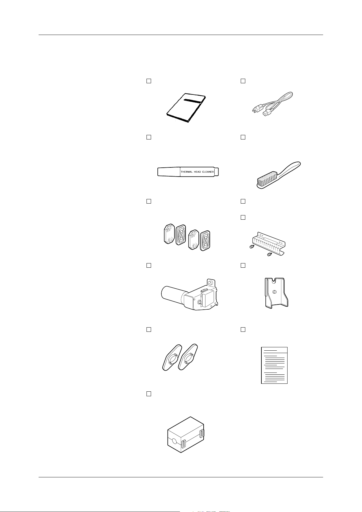
1.4.1 Accessories
When unpacking the printer, please make sure all accessories are
packed with the printer.
✓
Owner’s Manual (1 pc.)
Thermal Head Cleaner (1 pc.)
(24089500013)
Fan Filter (2 sets.)
(FMBB0046401)
Power Cord (1 pc.)
(FBC B0030202)
Feed Roller Brush (1 pc.)
(FMQB0047001)
*To be used exclusively for
the Feed Roller
Media Slide (1 pc.)
(FMCC 0032001)
Black Screw (2 pcs.)
(HAA-0007002)
Supply Shaft Holder (1 pc.)
(FMBD 0038901)
Supply Roll Holder (2 pcs.)
(FMHD0007502)
Ferrite Core (1 pc.)
(HGA-0068001)
*Used for RS-232C
Supply Shaft Holder Stand
(FMBB0047401)
Unpacking Instructions
(1 pc.)
(1pc.)
2
Page 11
Chapter 1 Product Overview
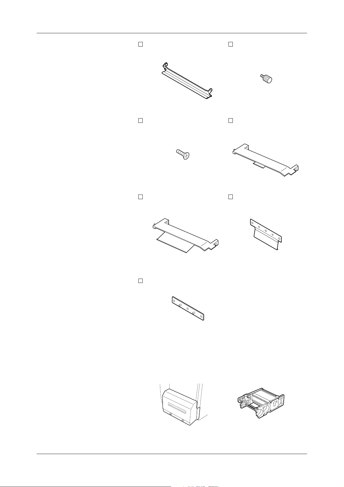
1.4.2 Cool Release
Enhancement Kit
Ribbon Plate (2 pcs.)
(FMCB 0095301)
D-3x5 Screw (6 pcs.)
(X0140305130)
SP Ribbon Guide (B) (1 pc.)
(FMCB0095501)
Mounting Screw (2 pcs.)
(FMDB 0079501)
SP Ribbon Guide
(FMCB0095601)
Ribbon T ension Sheet
(FMQC0035901)
(A) (1 pc.)
(2 pcs.)
1.4.3 Options
Sheet Fixing Plate (2 pcs.)
(FMEB0116901)
The following two options are available for the CB-426-T3 two-color
printer:
• The CB-1204-QM Cutter Module, which is used to cut media
repeatedly.
• The CB-1004-QM Ribbon Module, to be used as a spare ribbon
module.
Cutter Module Ribbon Module
3
Page 12
Chapter 1 Product Overview
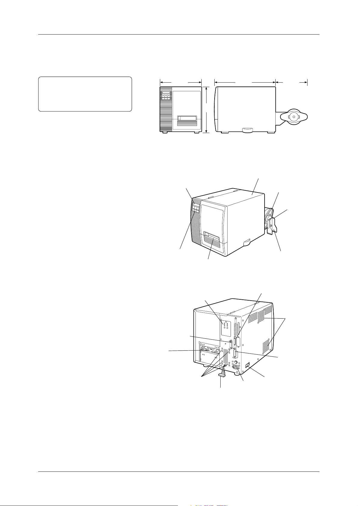
1.5 Appearance
1.5.1 Dimensions
Note:
Depth is 34.4 inches (875mm) when
the Cutter Module is installed on the
printer.
1.5.2 Front View
The names of the parts or units introduced in this section are used in
the following chapters.
13.7(350)
15.1
(385)
20.4(520)
11.0(280)
Dimensions in inches + (mm)
Top Cover
Message Display (LCD)
Supply Roll Holder
Supply Shaft Holder
1.5.3 Rear View
Operation Panel
Media Sensor Adjuster
Expansion I/O
Interface Connector
Media Inlet
Supply Shaft Holder Slots
Supply Shaft Holder Stand
Media Outlet
Serial Interface Connector
(RS-232C)
Air Vents
(Cooling Fans)
Parallel Interface
Connector
(Centronics)
Power Switch
AC Power Inlet
Harness
4
Page 13
Chapter 1 Product Overview
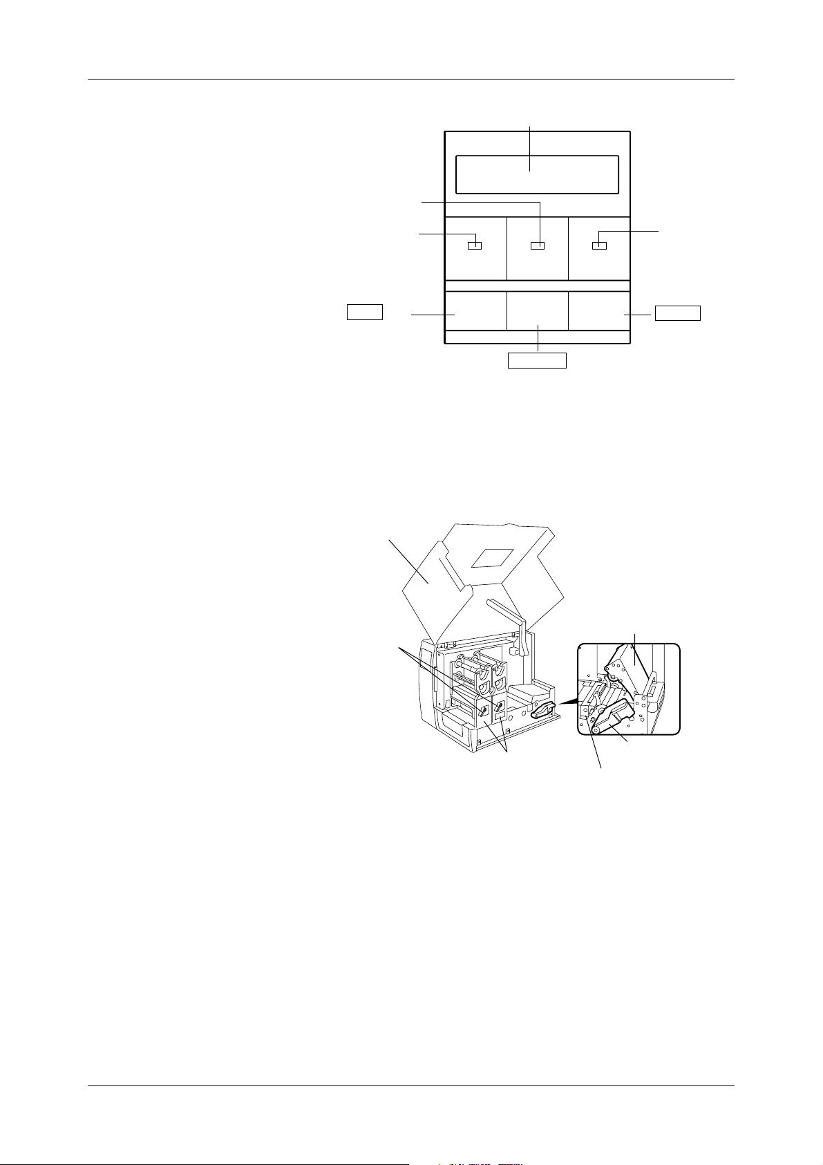
1.5.4 Operation Panel
1.5.5 Interior
Message Display (LCD)
ON LINE LED
(Green)
POWER LED
(Red)
FEED Key
POWER ON LINE ERROR
FEED RESTART PAUSE
RESTART Key
ERROR LED
(Green)
PAUSE Key
Please see Appendix 3 for further information about the Operation
Panel.
Top Cover
Head Lever
Ribbon Module
Pinch Roller Unit
Pinch Roller Lever
Media Pressure Plate
5
Page 14
2. Printer Installation
This chapter describes in detail how to set up the printer to get ready
for printing.
Chapter 2 Printer Installation
2.1 Installing the
Accessories
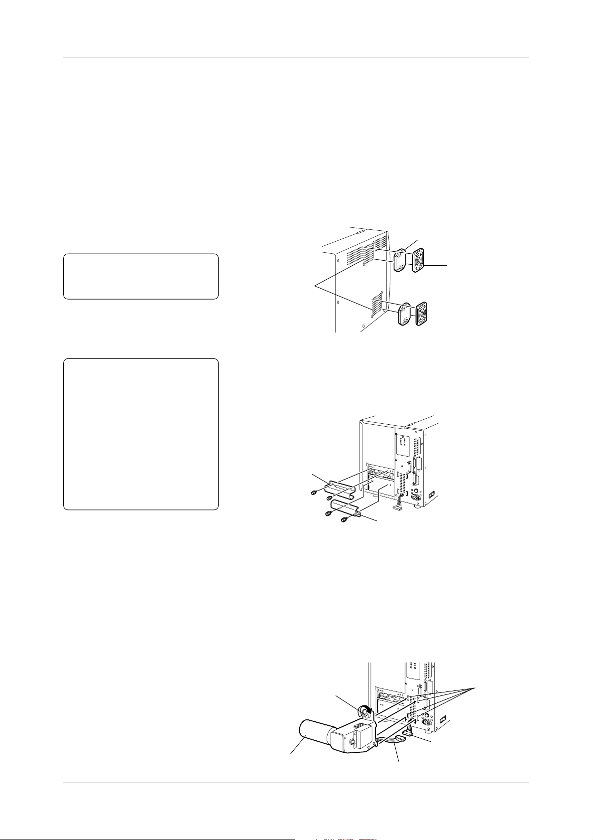
2.1.1 Fan Filters
Note:
Please clean the Filter Pads
periodically. See Section 5.1.3.
2.1.2 Media Slide
Notes:
• Either a roll of labels or tags can
be loaded in the printer.
• In this Owner's Manual, labels and
tags are generically called
"media".
• TOSHIBA TEC recommends that
labels are rolled outside, and the tags
are r olled inside. The media loading
procedur e depends on which type of
media is going to be loaded. See
Section 2.5 for more detail.
First install the accessories on the printer.
1
Unpack the Fan Filters.
2
Mount the Fan Filters over the Air Vents.
Filter Pad
Filter Retainer
Air Vents
(Cooling Fans)
Attach the Media Slide with the two supplied black screws.
When loading a roll of labels, fit the Media Slide on the screw holes
above the Media Inlet.
or
When loading a roll of tags, fit the Media Slide on the screw holes
below the Media Inlet.
Media Slide (for labels)
2.1.3 Supply Shaft Holder
6
Media Slide (for tags)
1
Connect the Supply Shaft Holder Harness to the harness attached
on the rear of the printer.
2
First hook the lower parts of the Supply Shaft Holder into the
lower two Supply Shaft Holder Slots on the rear of the printer.
Then fix the Supply Shaft Holder in place by tightening the screw .
T o remove the Supply Shaft Holder from the printer, just reverse the
installation procedure.
Screw
Harness
Supply Shaft Holder
Supply Shaft Holder Harness
Supply Shaft
Holder Slots
Page 15
Chapter 2 Printer Installation
2.2 Connecting the
Printer to Your
Computer
Note:
The interface cable is not included
in the accessories.
The printer can be connected to any computer, since it supports both
serial and parallel interface cables. Before connecting the printer,
please make sure which interface cable will be used.
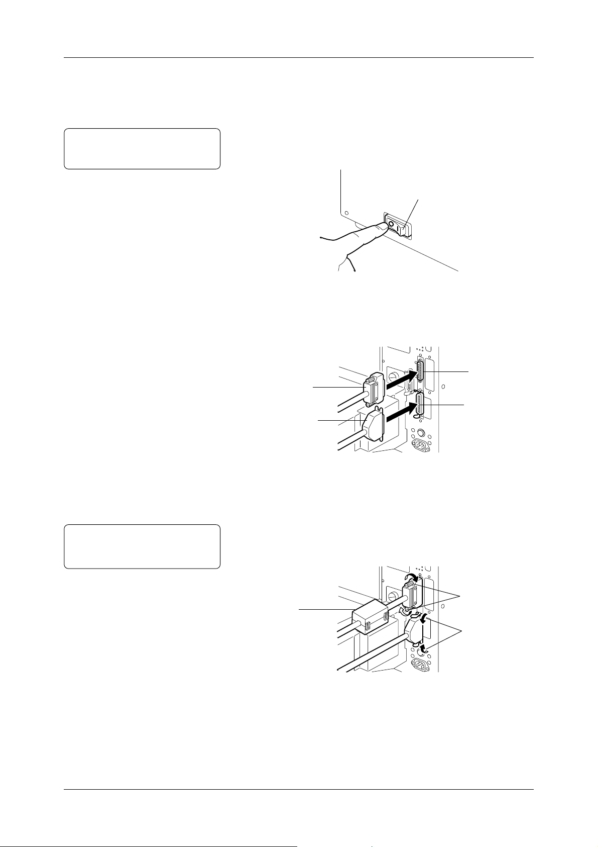
1
Be sure that both printer and computer are turned off.
(o) indicates OFF.
Power Switch
2
Connect the interface cable to the interface connector on the
printer. As illustrated below, connect the interface cable to either
of the interface connectors, depending on which interface cable
will be used.
Note:
Please refer to the user's manual of
the computer.
Serial Interface
Parallel Interface
3
Secure the cable with the clamps or screws.
4
When using the serial interface cable, attach the supplied ferrite
Cable
Cable
Serial Interface
Connector
Parallel Interface
Connector
core to the cable.
5
Connect the interface cable to the interface connector on the
computer.
Screws
Ferrite Core
(For Serial Interface
Cable)
Clamps
7
Page 16
Chapter 2 Printer Installation
2.3 Connecting
the Power
Cord
CAUTION!
• Please turn off the printer before connecting the power cord,
as this may cause an electric shock or damage to the printer.
• Please use the supplied power cord only. Use of other cords
may cause an electric shock or a fire.
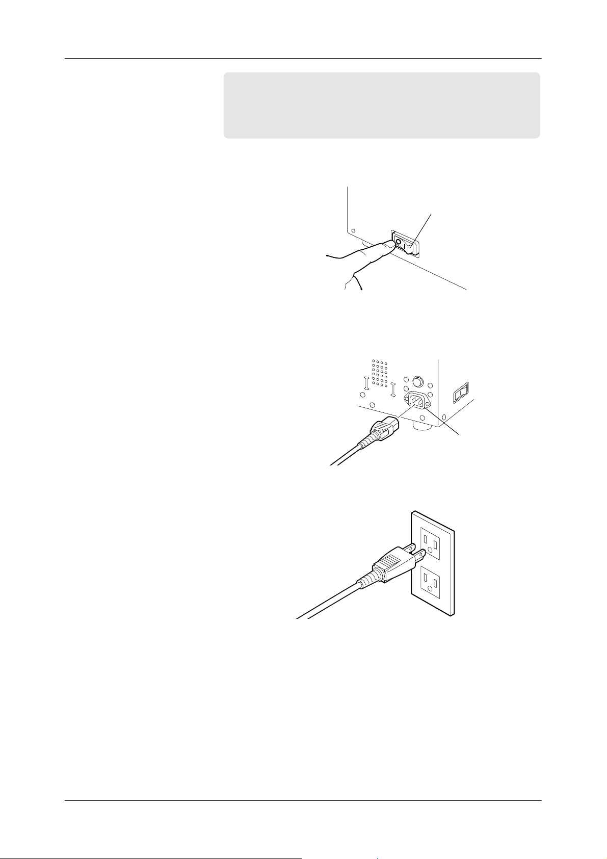
1
Be sure that both printer and computer are switched OFF.
(o) indicates OFF.
Power Switch
2
Connect the supplied power cord to the AC Power Inlet of the
printer.
3
Plug the power cord in an outlet.
AC Power Inlet
8
Page 17
Chapter 2 Printer Installation
2.4 Turning on/off
the Printer
2.4.1 Turning on the
Printer
When turned on, the printer checks the print head and memory.
When turned off, the printer will lose data in non-volatile memory.
CAUTION!
Use the power switch to turn on/off the printer. Unplugging
the power cord for turning on/off the printer may cause a fire,
an electric shock, or damage to the printer.
Important!
When the printer is connected to the computer,
• Turn ON the printer before turning on the computer.
• Turn OFF the computer before turning off the printer.
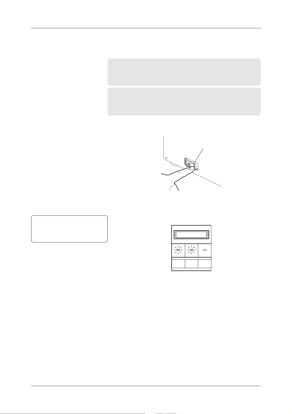
1
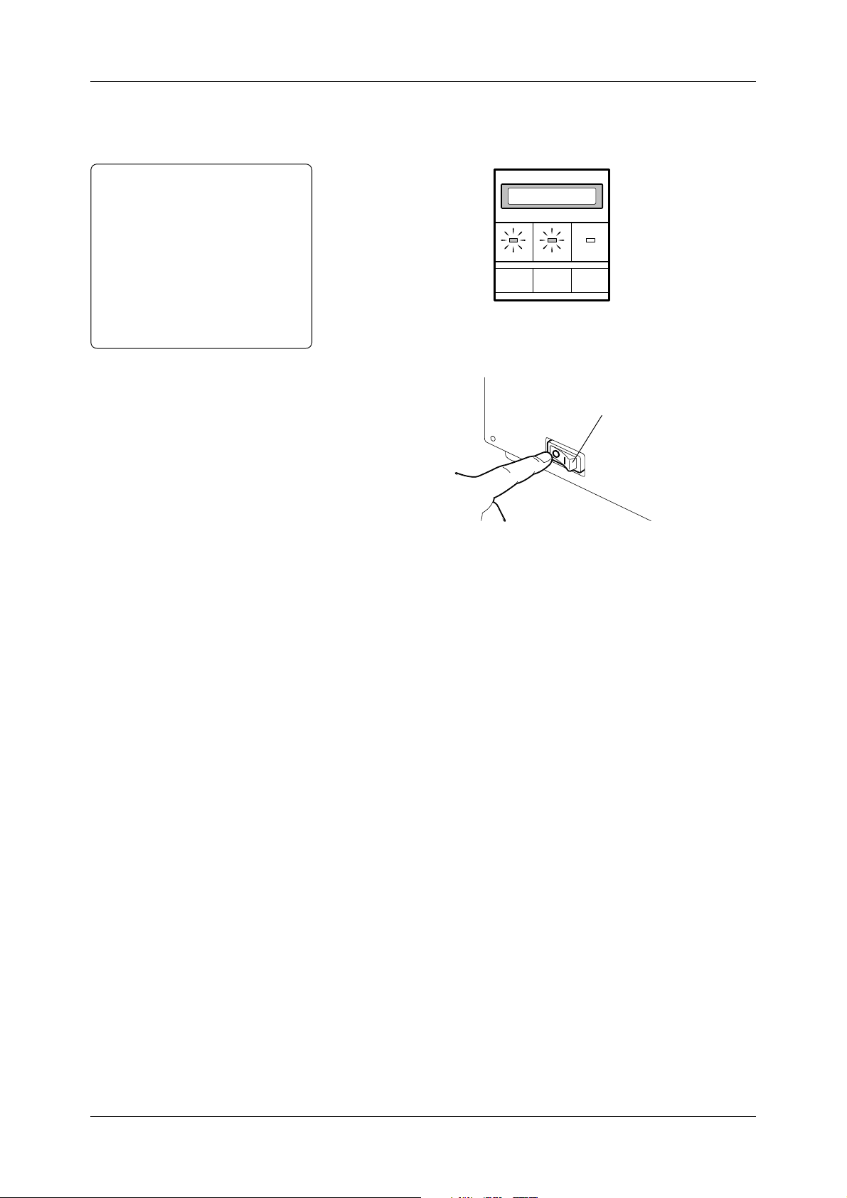
Turn on the printer. ( ❘ ) indicates ON.
Power Switch
Note:
Just in case the printer is not turned
on, or any error message appears,
please see Chapter 6.
2
The “ON LINE” message appears on the Message Display. The
POWER LED illuminates green. Then the ON LINE LED also
illuminates green.
ON LINE
POWER ON LINE ERROR
FEED RESTART PAUSE
9
Page 18
Chapter 2 Printer Installation
2.4.2 Turning off the
Printer
CAUTION!
• Do not turn off the printer
while a label is being issued,
as this may cause a paper jam
or damage to the printer.
• Do not turn off the printer
when the ON LINE LED is
blinking, as this may cause
damage to the computer
connected to the printer.
1
When turning off the printer, make sure of the following:
• The “ON LINE” message is shown on the Message Display.
• Both POWER and ON LINE LED’s are illuminated.
ON LINE
POWER ON LINE ERROR
FEED RESTART PAUSE
2
Turn off the power switch.
Power Switch
10
Page 19
Chapter 2 Printer Installation
2.5 Loading the
Media
Labels or tags can be loaded in the printer. The media loading
procedure depends on which media is going to be used.
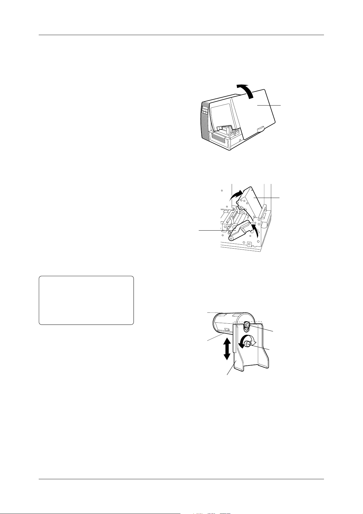
1
Open the Top Cover.
Top Cover
2
Lift the Pinch Roller Lever to the ROLLER RELEASE position
to open the Pinch Roller Unit.
Pinch Roller Unit
Note:
The Supply Shaft cannot be kept level
because of its weight, as the printer
becomes older . So befor e loading the
media, adjust the Supply Shaft so that
it can be kept level.
Pinch Roller Lever
(To ROLLER RELEASE)
3
Loosen the screw on the Supply Shaft Holder Stand.
4
Fit the Supply Shaft Holder Stand to the Supply Shaft, as illustrated
below . The Supply Shaft Holder Stand moves up or down so that
the Supply Shaft is kept level.
Supply Shaft
Screw
Supply Shaft Holder Stand
5
Remove the Supply Shaft Holder Stand from the Supply Shaft,
when adjustment to its height is complete.
11
Page 20
2.5 Loading the
Media (Cont.)
Chapter 2 Printer Installation
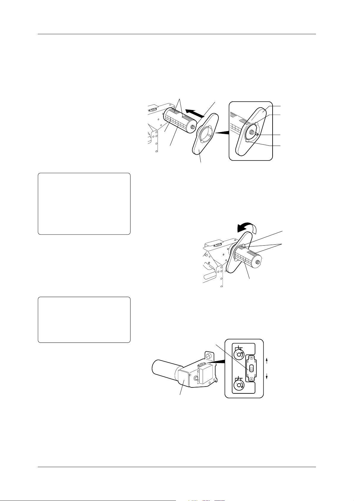
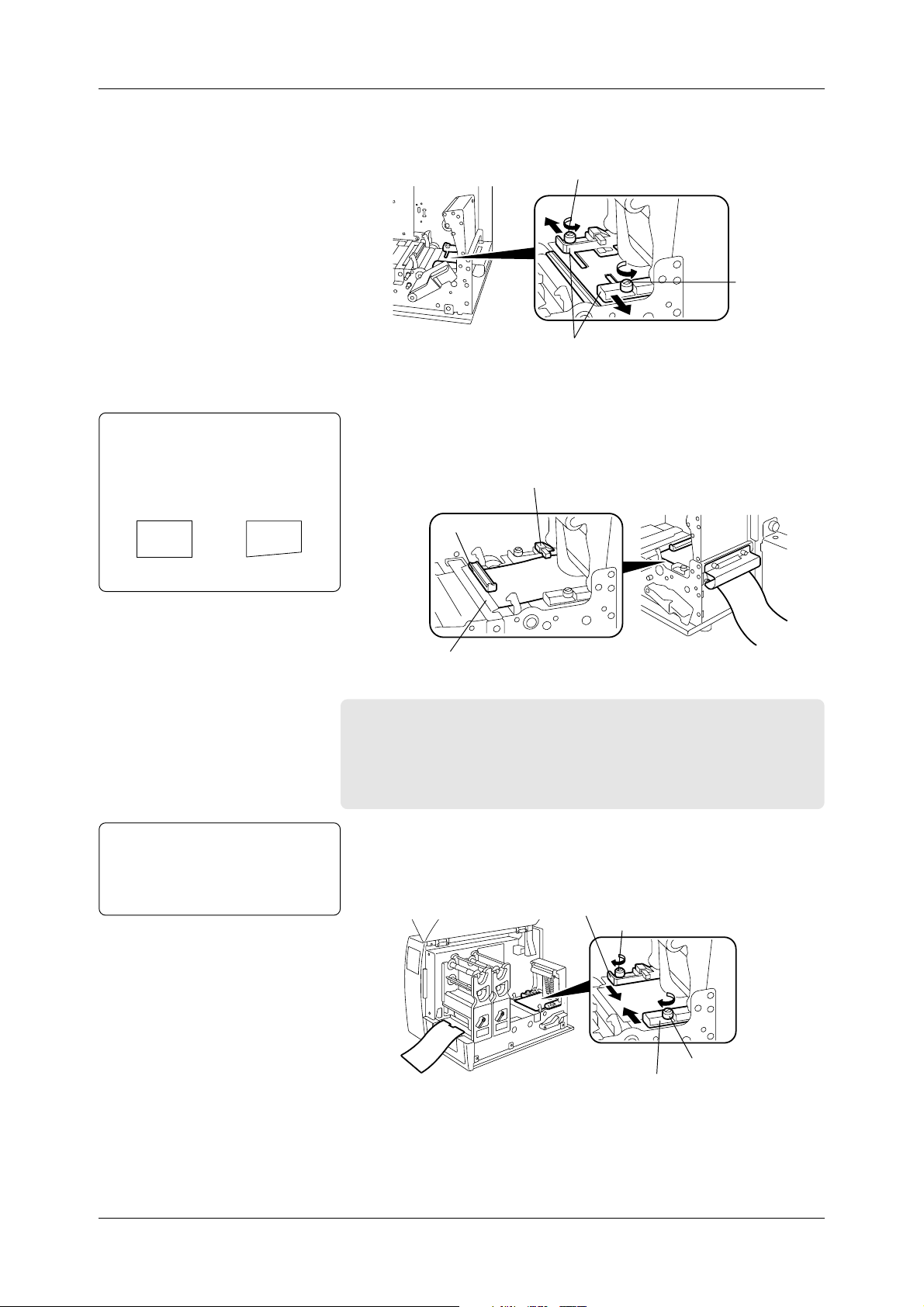
6
Turn the Supply Shaft so that the notches face upward, and the
marks face the Media Inlet.
7
To attach the Supply Roll Holder (inside), fit the tooth of the
Supply Roll Holder to the groove of the Supply Roll Shaft. Turn
the Supply Roll Holder clockwise to the end.
CAUTION!
Do not push into the Supply
Roll Holder (inside) with the
claw locked in the notches, as
this may cause damage to the
claw or notches.
See Section 2.5.1 for more
detail.
Notches
Marks
Supply Shaft
8
Push the Supply Roll Holder (inside) to the end of the Supply
Groove
Supply Roll Holder
Claw
Tooth
Claw
Supply Roll Holder
Shaft. Then turn the Supply Roll Holder counterclockwise so
that the claw is locked into the notch. When inserting the Supply
Roll Holder into the Supply Shaft, more pressure should be applied
when passing over the roller on the way to the end of the Supply
Shaft.
Claw
Notches
Note:
The media is rolled either outside or
inside, depending on the type of media
that is loaded. Whichever media is
used, load it with print side facing up.
See Appendix 1 for more detail.
Marks
9
Switch the Back T ension Selector, depending on whether the media
is rolled outside or inside. Switch the Selector to A for the media
rolled outside. Switch it to B for the media rolled inside, as
indicated by the arrows.
Back Tension Selector
A
Media rolled outside
Media rolled inside
B
Supply Shaft Holder
10
Measure width of the media that will be loaded.
12
Page 21
2.5 Loading the
Media (Cont.)
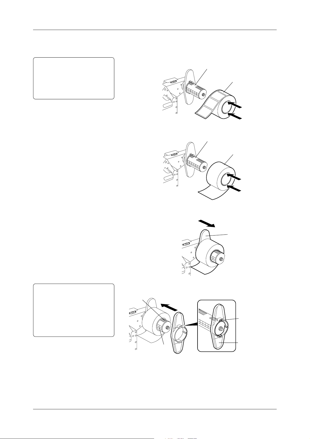
Note:
When inserting a roll of labels or
tags, push on the media core only.
Otherwise, core material drags
against the Supply Shaft causing
telescoping of the media supply roll.
Chapter 2 Printer Installation
11
Based on width of the media measured in Step 10, push the media
into the Supply Roll Holder (inside), and place it with reference
to the marks on the Supply Shaft.
• Loading a roll of labels
Supply Shaft
Labels
• Loading a roll of tags
Supply Shaft
Tags
12
Slide the Supply Roll Holder (inside) to the loaded media.
Supply Roll Holder
CAUTION!
To remove the Supply Roll
Holder (outside), turn it to
disengage the claw from the
notches. Otherwise, the claw or
the notches may be damaged.
See Section 2.5.1 for more
detail.
13
Slide the Supply Roll Holder (outside) to the loaded media.
Notches
Claw
Supply Shaft
Supply Roll Holder
(Outside)
13
Page 22
2.5 Loading the
Media (Cont.)
Note:
Make sure that the leading edge of
media is cut straight before inserting
the media into the printer , as this may
cause a media jam.
Chapter 2 Printer Installation
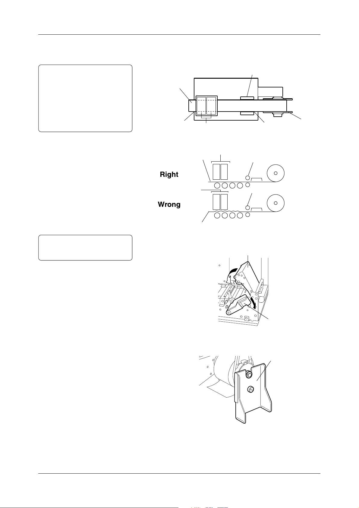
14
Loosen the two screws. Slide the Media Guides in the direction
of the arrows below until they stop (completely open).
Screw
Screw
Media Guides
15
Unroll about 1.5 to 2 inches (40 to 50cm) of the media.
16
Insert the media into the Media Inlet. Make sure that the media
passes under the Media End Sensor, the media sensor and the
Media Pressure Plate.
Media End Sensor
Media Sensor
Right Wrong
CAUTION!
Do not over tighten the two
screws, as this may cause
damage to the Media Guides.
Media Pressure Plate
Important!
• According to the media is loaded, adjust the position of the
media sensor. See Section 2.6 for more detail.
• Whenever the type of media is changed, adjust sensitivity
of the media sensor. See Section 2.7 for more detail.
17
Slide the Media Guides in the direction of the arrows below until
both guides come in contact with the media (media should be in
center of media path). Hand tighten the two screws.
Media Guide
Screw
14
Screw
Media Guide
Page 23
2.5 Loading the
Media (Cont.)
Notes:
• Pass the media straight from the
Supply Holder Unit to the Media
Outlet to avoid skewing.
• Use the marks at the Media Slide
and the Media Outlet so that the
media can be centered.
• Be sure to take up any slack in the
media.
Chapter 2 Printer Installation
18
Feed the media to the Media Outlet manually until its leading
edge comes out of the Media Outlet.
(Top View of the Printer)
Media Guide
Media
Media Outlet
Print Head Blocks
Media Inlet
Supply Roll
Holder
Note:
Push down the Pinch Roller Unit
gently on the “PUSH HERE” label.
(Side View of the Printer)
Print Head Blocks
Media
Print Head Blocks
Media
19
Push down the Pinch Roller Unit until it is hooked. Then push
Pinch Roller
Pinch Roller
down the Pinch Roller Lever to the ROLLER LOCK position.
[PUSH HERE]
Pinch Roller Lever
(To ROLLER LOCK)
20
Reinstall the Supply Shaft Holder Stand to the Supply Shaft Holder,
whose level is adjusted in Steps 3 to 5.
Supply Shaft Holder Stand
15
Page 24
2.5 Loading the
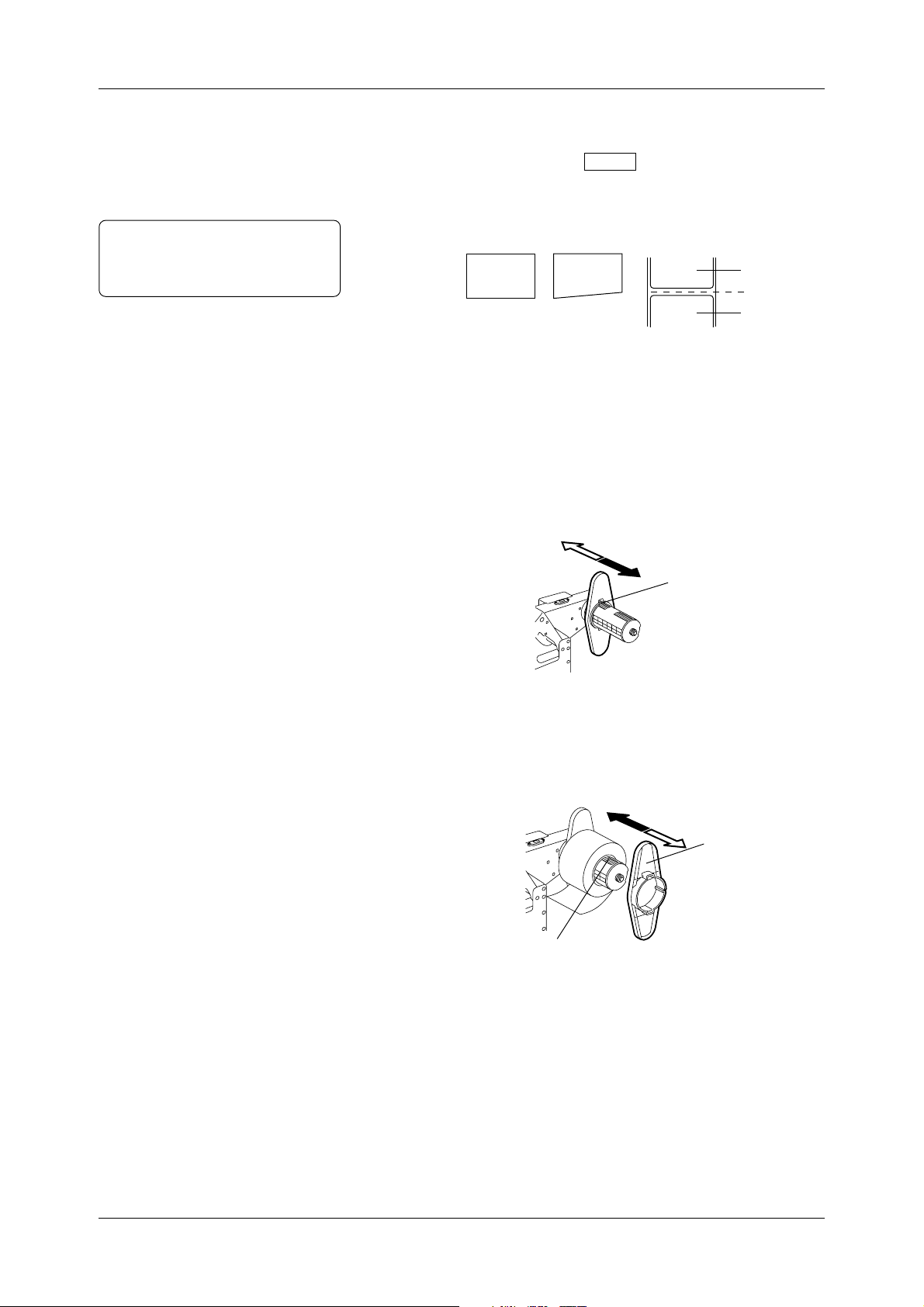
Media (Cont.)
Note:
When loading labels, make a straight
cut in the gap area between labels.
Chapter 2 Printer Installation
21
Close the Top Cover gently. Make sure that the POWER LED
and ON LINE LED are illuminated, and that the “ON LINE”
message is shown. Press the FEED key on the Operation Panel
to feed the media about 1 inch (20 to 30cm). Check that the media
is fed successfully.
Label
Cut here.
Right Wrong
Label
2.5.1 Additional
Information
This section contains more information concerning the care that should
be taken when loading the media.
• The figure below indicates the direction the Supply Roll Holder
(inside) can be moved with the claws of the Supply Roll Holder
locked into the notches.
Wrong
Supply Roll Holder
(Inside)
• The figure below indicates the direction the Supply Roll Holder
(outside) can be moved with the claws of the Supply Roll Holder
locked into the notches.
Right
Notches
Right
Wrong
Supply Roll Holder
(Outside)
16
Notches
Page 25
Chapter 2 Printer Installation
2.6 Sensor
Adjustments
2.6.1 Black Mark
Sensor
This section describes in detail how to adjust the media sensor
positions and their sensitivity.
Whenever the type of media is changed, a positional adjustment of
the media sensor is needed. The media sensors are designed to keep
positional alignment of the image on each label or tag when issued.
Important!
NEVER skip the media sensor positional adjustment.
The printer has two types of media sensors: Black Mark Sensor and
Feed Gap Sensor.
The Black Mark Sensor (reflective sensor) is used to detect black
marks on the back of the media by the reflection of light. On the
other hand, the Feed Gap Sensor (transmissive sensor) is used to detect
gaps by the transmission of light.
Which media sensor to adjust depends on the type of media loaded.
When the media with black marks on the BACK is loaded, adjust the
Black Mark Sensor (reflective sensor) position as follows:
1
Open the Top Cover.
2
Lift the Pinch Roller Lever to the ROLLER RELEASE position
to open the Pinch Roller Unit.
Note:
“1” marked on the sensor indicates
the Black Mark Sensor position.
Note:
See A1.3.3 for black mark specifications.
3
Align the Media Guides to the width of the media.
4
Fold the media so that a black mark faces upward.
5
Insert the media into the Media Inlet.
6
Turn the Media Guide Knob, and move the media sensor so that it
is positioned at the center of the black mark.
Media Sensor
Media Guide Knob
7
The Black Mark Sensor Position Adjustment has been completed.
Black Mark detected here
Sensor
Media
Black Mark
17
Page 26
Chapter 2 Printer Installation
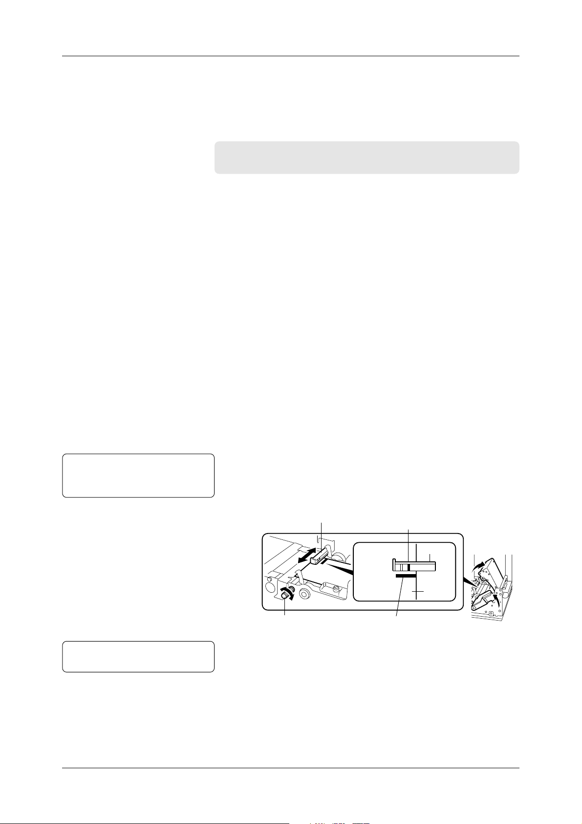
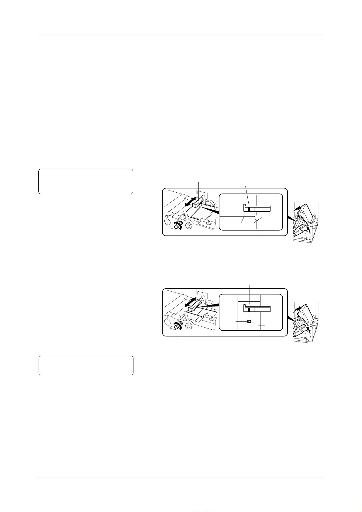
2.6.2 Feed Gap Sensor When the media with gaps or rectangular holes is loaded, adjust the
Feed Gap Sensor (transmissive sensor) position as follows:
1
Open the Top Cover.
2
Lift the Pinch Roller Lever to the ROLLER RELEASE position
to open the Pinch Roller Unit.
3
Align the Media Guides to width of the media.
4
Insert the media into the Media Inlet.
• If the media with gaps is loaded, go to Step 5.
• If the media with rectangular holes is loaded, go to Step 6.
5
Turn the Media Guide Knob, and move the media sensor so that
the gap between labels will pass under the sensor.
Note:
“2” marked on the sensor indicates
the Feed Gap Sensor position.
Media Sensor
Gap detected here
Sensor
Note:
See A1.3.2 for gap or hole specifications.
Label
Gap
Media Guide Knob
6
Turn the Media Guide Knob, and move the media sensor so that it
Backing Paper
is positioned at the center of the rectangular hole.
Media Sensor
Media Guide Knob
7
The Feed Gap Sensor Position Adjustment has been completed.
Hole detected here
Hole
Sensor
Media
18
Page 27
Chapter 2 Printer Installation
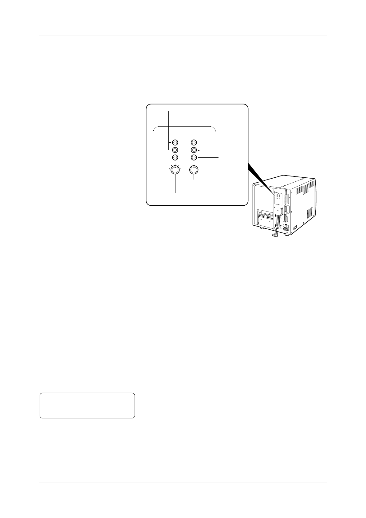
2.6.3 Media Sensor
Sensitivity
Adjustment
Whenever the type of media is changed, adjust the media sensor
sensitivity.
Please note that the adjustment procedures are slightly different,
depending on which type of media loaded.
Media Sensor Adjustor
Feed Gap Sensor Lamp
Black Mark Sensor Lamp
Green
Red
Black Mark Sensor
Adjusting Knob
Feed Gap Sensor Adjusting Knob
Note:
As soon as the upper two lamps
illuminate green, stop turning the knob.
Black Mark Sensor Sensitivity Adjustment
1
Open the Top Cover.
2
Lift the Pinch Roller Lever to the ROLLER RELEASE position
to open the Pinch Roller Unit.
3
Insert the media with black marks into the Media Inlet so that the
Black Mark Sensor can detect the WHITE part of the media.
4
Lock the Pinch Roller Unit.
5
Turn on the printer.
6
Turn the Black Mark Sensor Adjusting Knob to the left most
position.
7
Keep turning the knob clockwise slowly. When the upper two
Black Mark Sensor Lamps illuminate green, the adjustment is
complete.
19
Page 28

Chapter 2 Printer Installation
2.6.3 Media Sensor
Sensitivity
Adjustment (Cont.)
Note:
As soon as the upper two lamps
illuminate green, stop turning the knob.
Feed Gap Sensor Sensitivity Adjustment
(for Label with Gaps)
1
Open the Top Cover.
2
Lift the Pinch Roller Lever to the ROLLER RELEASE position
to open the Pinch Roller Unit.
3
Insert the label with gaps into the Media Inlet so that the Feed
Gap Sensor can detect the LABEL part.
4
Lock the Pinch Roller Unit.
5
Turn on the printer.
6
Turn the Feed Gap Sensor Adjusting Knob to the left most position.
7
Keep turning the knob clockwise slowly. When the upper two
Feed Gap Sensor Lamps illuminate green, the adjustment is
complete.
Note:
As soon as the upper two lamps
illuminate green, stop turning the knob.
Feed Gap Sensor Sensitivity Adjustment
(for Media with Rectangular Holes)
1
Open the Top Cover.
2
Lift the Pinch Roller Lever to the ROLLER RELEASE position
to open the Pinch Roller Unit.
3
Insert the media with rectangular holes into the Media Inlet so
that the Feed Gap Sensor can detect the PAPER part.
4
Lock the Pinch Roller Unit.
5
Turn on the printer.
6
Turn the Feed Gap Sensor Adjusting Knob to the left most position.
7
Keep turning the knob clockwise slowly. When the upper two
Feed Gap Sensor Lamps illuminate green, the adjustment is
complete.
20
Page 29
Chapter 2 Printer Installation
2.7 Loading the
Ribbons
(for Hot Release
Ribbons)
Note:
Media Width does not include width
of the backing paper.
2.7.1 Ribbon Positions
Important!:
When loading the ribbons, please
do not forget to specify the ribbon
colors in the printer properties.
See Section 3.4.3 for more detail.
This section describes in detail how to load the ribbons in the printer .
Please use the ribbon width corresponding to the media width from
the table shown below.
Ribbon Width
2.7 (68)
3.5 (88)
4.3 (109)
Media Width
2 to 2.6 (50 to 65)
2.6 to 3.4 (65 to 85)
3.4 to 4.4 (85 to 110)
Dimensions in inches + (mm)
There are two types of ribbons: high-performance Hot Release Ribbons
that provide fast, quality print, and the popular Cold Release Ribbons.
This section focuses on how to load the Hot Release Ribbons.
See Section 2.8 for loading procedures of the Cold Release Ribbons.
Also refer to the table in Section 3.8.2 for specific information about
each ribbon type. If the ribbon type to be used cannot be found in the
table, contact an authorized sales representative.
Please load the ribbons, as illustrated below.
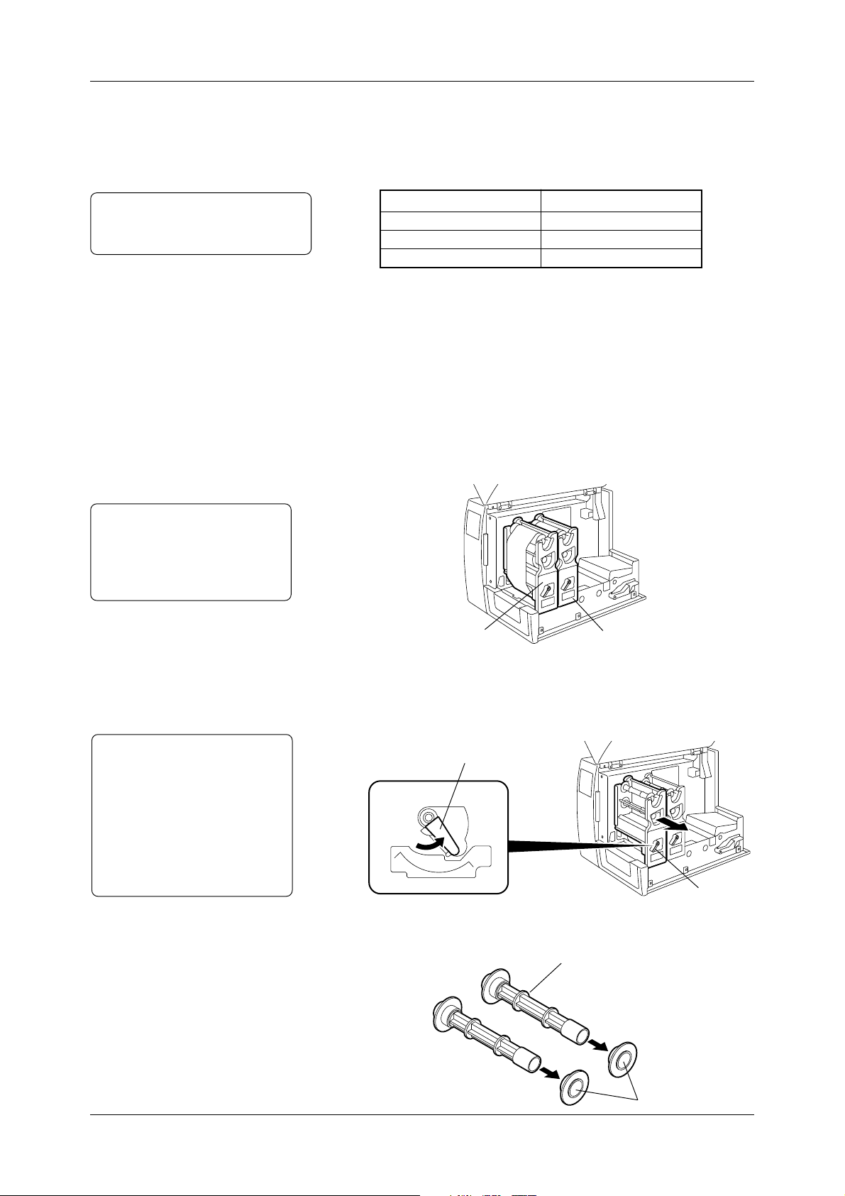
2.7.2 Loading
Procedure
Notes:
• Turn the Head Lever to the
OPEN position completely, or
the Ribbon Module cannot be
removed.
• Do not bend, drop, or give any
shock to the Ribbon Module.
Distortion of the Ribbon
Module may cause poor print.
Head 2 (Front)
1
Open the Top Cover.
2
Turn the Head Lever to the OPEN position. Pull out each Ribbon
Head 1 (Back)
Module in the direction of the arrow , and remove it from the printer.
Head Lever
HEAD
LOCK
3
Remove the two Ribbon Shafts from the Ribbon Module. Remove
OPEN
Ribbon Module
the Ribbon Stopper from each Ribbon Shaft.
Ribbon Shaft
Ribbon Stoppers
21
Page 30
2.7.2 Loading
Procedure (Cont.)
Chapter 2 Printer Installation
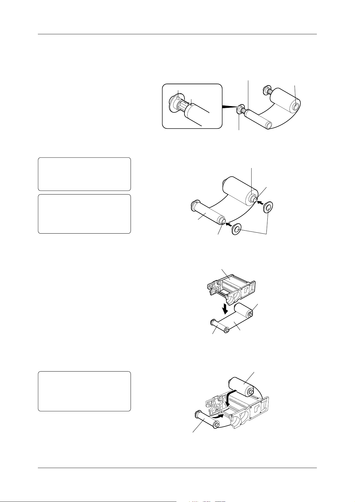
4
Insert the Ribbon Shaft into the Ribbon Winding Core. Fit the
protrusion of the Ribbon Shaft into the notch of the Ribbon
Winding Core. Insert the other Ribbon Shaft into the Ribbon Feed
Core in the same manner.
Ribbon Winding Core
Protrusion
Notch
Ribbon Shaft
5
Attach the Ribbon Stoppers gently to each Ribbon Shaft.
Ribbon Feed Core
CAUTION!
Push in the Ribbon Stoppers
gently. Otherwise, damage
may occur.
Note:
Please make sure that the Ribbon
Stoppers are completely inserted into
the Ribbon Winding Cor e and Ribbon
Feed Core respectively.
Ribbon Feed Core
Ribbon Shaft
Ribbon Winding Core
Ribbon Shaft
6
Unroll about 1 inch (30cm) of the ribbon. Place the Ribbon Module
Ribbon Stoppers
on the ribbon.
Ribbon Module
Ribbon Feed Core
Ribbon Winding Core
Ribbon
CAUTION!
Loading the ribbon upside
down may cause damage to
the print head, as well as print
failure.
22
7
Insert the Ribbon Feed Core, and then the Ribbon Winding Core
on the Ribbon Module, as illustrated below.
Ribbon Feed Core
Ribbon Winding Core
Page 31

Chapter 2 Printer Installation
2.7.2 Loading
Procedure (Cont.)
8
T ake up any slack in the ribbon. Replace the Ribbon Module into
the print head block by sliding it into the end.
Ribbon Module
Ribbon
Print Head Block
9
Turn the Head Lever to the LOCK position to secure the Ribbon
Module. Take up any ribbon slack one more time by turning the
Ribbon Winding Core.
Ribbon Winding Core
10
Load the other three ribbons in the same manner.
11
Close the Top Cover.
Ribbon Module
23
Page 32

Chapter 2 Printer Installation
2.8 Loading the
Ribbons
(for Cold Release
Ribbons)
Notes:
• Please see Section 1.4.2 for the part
illustrations.
• Installing the Cool Release
Enhancement Kit allows a variety
of ribbons to be loaded.
2.8.1 Precautions
This section describes how to load the popular Cold Release Ribbons.
To identify a ribbon type to be loaded, refer to the table in Section
3.8.2 or contact an authorized sales representative. Before loading
the Cold Release Ribbons, install the Cool Release Enhancement Kit
that is composed of the following accessories.
Part Name
Ribbon Plate
Mounting Screw
D-3x5 Screw
SP Ribbon Guide (A)
SP Ribbon Guide (B)
Ribbon T ension Sheet
Sheet Fixing Plate
1
Depending on the operating temperature or print patterns, ribbon
wrinkles or blurred printing may occur. To solve this problem,
adjust the print density as follows:
• When the ribbons wrinkle, decrease the print density.
• When the blurred printing occurs, increase the print density.
To change the print density, see Section 3.7.2 for more detail.
Quantity
2 pcs.
2 pcs.
6 pcs.
1 pc.
1 pc.
2 pcs.
2 pcs.
2
When using the Cold Release Ribbons in high temperature (about
105°F/40°C), the sound of the ribbon being separated from the media
may be heard. But that does not impact upon print quality .
24
Page 33

Chapter 2 Printer Installation
2.8.2 Installing the Ribbon
Plate
WARNING!
During normal printer operations, the print head will become hot. Care
should be used when handling the print head to avoid personal injury.
1
Remove all Ribbon Modules from the print head blocks. Then
lift one of the print head blocks.
Print Head Block
2
Hold the Ribbon Plate with the pin facing inside and downwards,
as illustrated below.
Print Head Block
Print Head Block
Notes:
• Be sure to return the print head to
the original position.
• Tighten the screws so as not to
damage the screw threads.
Ribbon Plate
3
First position the Head Positioning Plate (opposite the pin side),
Pin
into the small rectangular groove. Keep the Head Positioning
Plate flush against the groove, as illustrated below.
When attaching the Ribbon Plate to the print head block, make
sure that the Head Positioning Plate makes full contact with the
small rectangular groove.
Groove
Head Positioning
Plate
Ribbon Plate
Print Head Block
Ribbon Plate
(Side View of Print Head Block and Ribbon Plate)
4
Slide the Ribbon Plate down slightly and insert the pin into the
hole on the back of the print head.
5
After the pin is inserted, slide the Ribbon Plate back in the direction
of the arrow and gently pull down the print head. Secure the Ribbon
Plate to the print head block by tightening the Mounting Screw.
Print Head Block
Mounting Screw
Print Head Block
Ribbon Plate
6
Repeat this procedure for installation of the other three print heads.
Pin
25
Page 34

2.8.3 Installing the SP
Ribbon Guides
Important!
• The SP Ribbon Guide (A) with the
small plastic film is exclusively for
Head 2.
• The SP Ribbon Guide (B) with the
large plastic film is for Head 1.
Chapter 2 Printer Installation
1
Remove the Guide Plates from the printer by lifting and pulling
them in the direction of the arrow.
Guide Plate
2
Install the SP Ribbon Guides (A) and (B) in the reverse order of
removal of the Guide Plates.
SP Ribbon Guide (A)
(for Head 2)
SP Ribbon Guide (B)
(for Head 1)
Plastic Plate (Small)
Plastic Plate (Large)
26
Page 35

Chapter 2 Printer Installation
2.8.4 Installing the Ribbon
Tension Sheet
Note:
Do not reinstall the Ribbon guide
Lever , Ribbon Guide Lever Shaft and
the D-3x6 screw because they ar e not
used after the ribbon tension sheet
has been installed.
1
Remove the Ribbon Guide Lever from the Ribbon Cassette by
removing the screw.
2
Fit the bosses on the Sheet Fixing Plate into the holes of the Ribbon
Tension sheet and the aluminum frame. Secure them with the
three D-3x5 screws.
Ribbon Cassette
D-3x5
Bosses
(A)
Aluminum Frame
D-3x6
(B)
Ribbon Guide Level
Ribbon Guide
Level Shaft
Sheet Fixing Plate
Ribbon Tension Sheet
(A)
(B)
27
Page 36

Chapter 2 Printer Installation
2.8.5 Loading the Cold
Release Ribbons
Note:
Selecting a wrong ribbon type may
cause blurred or blotted printing.
Be sure to select the pr oper ribbon
type.
Note:
Selecting a wrong ribbon motor
voltage may cause ribbon wrinkles
or blurred printing. Be sure to
enter the proper value.
After attaching the Cool Release Enhancement Kit, the Ribbon
Settings need to change. See Section 3.8.2 for more detail.
1
Open the Testing property page on the computer, click Ribbon
Settings, and open the Testing dialog.
2
Click the Type down arrow, and select Premium (either 109mm
or 68mm).
3
The Ribbon Motor Voltage may need to change.
28
Page 37

3. Printing
Chapter 3 Printing
Note:
In this chapter, unless otherwise
specified, “click” means click the left
mouse button once.
3.1 Installing the
Printer Driver
3.1.1 System
Requirements
This chapter explains how to print an image or bar code using the
Windows driver . First, it describes in detail how to install the printer
driver . Then it describes how to modify the printer settings and fine
adjustments to produce the best output. Finally it describes how to
print a label.
The chapter is organized as follows:
1
To install the printer driver, see Section 3.1.
2
To specify the printer properties, see Sections 3.2 to 3.8.
3
T o perform test printing, see Section 3.9.
4
To print an actual label from an application program, see Section
3.10.
To use the CB-426-T3 printer with Windows, the printer driver must
be installed on the computer. Labels or tags can easily be printed
from a variety of application software using the CB-426-T3 printer
driver.
You need an IBM PC/AT-compatible computer with:
Microsoft® Windows® 95/98, Windows NT® V ersion 4.0 W orkstation,
or Windows NT® Version 4.0 Server.
Pentium® 133MHz or greater recommended
16MB of available RAM or more (32MB recommended).
10MB or more of available hard-disk space.
3.1.2 Installation
Procedure
(For Windows
Notes:
•For further information about the
installation procedure for
Windows® NT , please contact your
authorized service representative.
• The printer driver may be upgraded
without notification. For further
information about the download of
the upgraded printer driver, please
access the following URL.
http://barcode.toshibatec.co.jp.
®
98)
This section has step-by-step procedures to install the TEC Printer
Driver Version 6.4 build 33 for Windows®98.
Preparation
Make preparations for the installation of the printer driver as follows:
1
Insert Disk 1 in the floppy disk drive.
2
Click the Start button. Then click Run.
3
Type “a:setup” in Open, and then click OK.
29
Page 38

3.1.2 Installation
Procedure (Cont.)
Chapter 3 Printing
4
TOSHIBA TEC PRINTER DRIVER Setup W izard is initiated.
Click Next.
5
To accept License Agreement, click Yes. If it is not acceptable,
click No. However, the printer driver cannot be installed.
30
6
Choose a destination folder to install COLOR. To install it in
C: \TEC_DRV\COLOR, click Next. The installation of COLOR
begins. To install it in another destination, click Browse.
Page 39

3.1.2 Installation
Procedure (Cont.)
Chapter 3 Printing
7
Remove Disk 1. Then insert the other disks in the floppy disk
drive, as instructed by the dialog box that appears on the screen.
Click OK to continue the set up.
8
Setup Complete appears, when the setup successfully completes.
Click Finish.
9
Start the Windows Explorer. Verify that the Color folder was
created in the TEC_drv folder on the C drive.
31
Page 40

Chapter 3 Printing
3.1.2 Installation
Procedure (Cont.)
Adding the Printer (For Windows®98)
Install the printer driver as follows:
1
Click the Start button. Choose Settings, and click Printers. The
Add Printer icon appears.
2
Double-click the Add Printer icon, and Add Printer W izard is
initiated. Click Next to add the CB-426 printer.
32
3
Choose whether the printer is used as Local Printer or Network
Printer. Then click Next.
Page 41

3.1.2 Installation
Procedure (Cont.)
Chapter 3 Printing
4
Click Have Disk.
5
Type in “C:\TEC_DRV\COLOR”, and click OK.
6
Choose CB-426-T3 from the printer list, and click Next.
33
Page 42

3.1.2 Installation
Procedure (Cont.)
Notes:
• The ECP Printer port is recommended.
• Please refer to the user's manual of
your computer for further information
regarding the setting of the ECP
Printer port.
Note:
If no printer driver has been installed
before, this printer will be used as a
default printer automatically.
Chapter 3 Printing
7
Choose the port that the printer is connected to, and click Next.
8
Type in a printer name that you prefer to use.
9
Select whether the printer will be used as the default printer for
all applications. Then click Finish.
34
10
Finally, make sure that the CB-426-T3 icon has been added in
Printers. Installation of the printer driver has been completed.
Page 43

Chapter 3 Printing
3.1.3 Uninstalling the
Printer Driver
Note:
Start uninstalling the printer driver
after closing all application programs.
Note:
Remove the icon by right-clicking the
icon, and choosing and clicking
Delete.
Perform the following steps to uninstall the printer driver.
1
Click the Start button. Choose Settings, and click Printers.
Choose the CB-426-T3 icon.
2
On the File menu, click Delete. Please be sure that the CB-426T3 icon is removed.
The printer driver is uninstalled now.
35
Page 44

Chapter 3 Printing
3.1.3 Uninstalling the
Printer Driver
(Cont.)
Important!
When upgrading the printer driver, the folder needs to be
deleted as follows:
1
Click the Start button. Choose Settings, and click Control Panel.
2
Double-click the Add/Remove Programs icon.
3
Add/Remove Programs Properties appears. Choose TOSHIBA
TEC PRINTER COLOR, and click Add/Remove.
4
The Confirm File Deletion dialog box appears. Click Yes, and
the removal of the printer driver begins.
5
The printer driver is removed successfully. Click OK.
36
Page 45

Chapter 3 Printing
3.2 Properties
3.2.1 Displaying Printer
Properties
This section summarizes the main properties that can be specified to
ensure the best printer performance.
Please refer to the later sections describing the property settings in
detail.
1
Click the Start button. Choose Settings, and click Printers.
2
On the File menu, click Properties. TEC CB-426-T3 Properties
appears.
37
Page 46

Chapter 3 Printing
3.2.2 Summary of
Properties
Note:
Some of the properties may have to
be set again in the application
programs.
This is a summary of the main properties for CB-426-T3.
• On the Page Setup property page, specify the default label size and
orientation settings. In addition, other label sizes can be created,
then accessed through your application’s page setup dialog.
See Section 3.3 for more detail.
• On the Graphics property page, how text and images will be
printed on the labels or tags can be specified.
See Sections 3.4 for more detail.
• On the Bar Fonts property page, internal bar code fonts can be
added, deleted, modified, imported, exported and viewed.
See Section 3.5 for more detail.
• On the Stock property page, print conditions including selection
of the media sensor to be used, the issue mode and fine adjustments
can be specified.
See Sections 3.6 for more detail.
• On the Options property page, the transfer mode of graphics data
and print density adjustments can be specified.
See Section 3.7 for more detail.
• On the Testing property page, the type of ribbon to be used, can
be specified. The Testing property page is also used for test print
and maintenance purposes.
See Section 3.8 for more detail.
• On the Regional Settings property page, the units of measurement
(inches or centimeters) and the language in which your driver is
displayed can be specified.
• On the About property page, the printer driver information that
includes the version number and licence agreement can be viewed.
38
Page 47

Chapter 3 Printing
3.3 Page Setup
This section describes in detail how to specify the default label size,
orientation and how to create other label sizes that then can be accessed
through an application’s page setup dialog.
Click the Page Setup tab to open the Page Setup property page.
3.3.1 Selecting a label size
Note:
The setting made in this section can
be saved in the file as a preferred
setting for a particular print job.
See Section 3.3.4 for more detail.
Click the Name down arrow to select a desired label size from the
predefined label sizes: 2 x 4, 4 x 4, 4 x 6 or User Defined.
• Use Import Stock List to import previously defined label sizes
from other compatible printer drivers.
• Use Export Stock List to save defined label sizes to a file so they
can later be imported into other printer drivers with this capability .
39
Page 48

Chapter 3 Printing
3.3.2 Creating a new label
size
To create your own label size :
1
Click New, and Edit Label Stock appears.
Note:
User Defined cannot be renamed.
Note:
Delete is grayed out when the
predefined label sizes ar e selected. In
other words, you cannot delete them.
2
Enter a new label stock name in Name.
3
Change Label Size (Width and Height) and Exposed Liner Width
(Left and Right). Click OK to return to the Page Setup property
page.
4
Click Edit to change the label name, label size, or exposed liner
size that is defined in Step 3.
5
To delete a label size that you created, select it in Name, and click
Delete. When the confirmation dialog box appears, click Yes.
40
Page 49

Chapter 3 Printing
3.3.3 Orientation
Notes:
• A preview will be shown, as each
option is selected.
• The setting made in this section can
be saved in the file as a preferred
setting for a particular print job.
See Section 3.3.4 for more detail.
Select the print image orientation to determine the direction that the
print image will be issued
• Click Portrait, and the bottom of the print image comes out of
the printer first.
• Click Landscape, and images are rotated 90° counterclockwise
from the portrait orientation. The left edge of the print image
comes out of the printer first.
• Click Portrait 180 °, and the top of the print image comes out of
the printer first.
• Click Landscape 180°, and images are rotated 90° clockwise from
the portrait orientation. The right edge of the print image comes
out of the printer first.
Note:
• Effects is not available for this
version.
41
Page 50

3.3.4 Miscellaneous
Chapter 3 Printing
Notes:
• When the page setup or print property
changing using the application
software under Windows®95, just in
case any application occurs, please
do not mark the Enable User
Commands checkbox.
• The User Commands specified
here can be saved in the file as the
preferred User Commands for a
particular print job.
See the Printing Prefer ences below .
• Click Copies to enter the default number of copies that the printer
will print.
• Click Advanced Options. The Advanced Options Screen appears
to implement the following functions:
User Commands
Printer commands can be added at the beginning or the end of a print
job.
Please note familiarity with application programs and commands is
required. Otherwise the printer may not function, as desired.
42
Page 51

Chapter 3 Printing
3.3.4 Miscellaneous
(Cont.)
Note:
Regardless of whether the Set Check
box is marked or not, the shaded area
will be enabled when saved as the
preferred settings.
See Sections 3.6.5 and 3.7.2 for more
detail.
Printing Preferences
• In Printing Preferences, the preferred settings can be saved in the
file for a particular print job. If several kinds of print jobs are
performed, it is strongly recommended to use this function to save
the preferred settings in the file for each print job.
When using Printing Preferences, the following settings can be
saved. For more details of each setting, see the section indicated
in the right column of the table below.
Tab
Page Setup
Graphics
Settings
Name
Orientation
User Commands
Dithering
Color Control
Print Method
Sensor
Label Gap
See Section ...
3.3.1
3.3.3
3.3.4
3.4.1
3.4.3
3.6.1
3.6.2
3.6.3
Issue Mode
Stock
Cut
3.6.4
Cut Interval
Feed (Fine Adjustment)
Back feed (Fine Adjustment)
Cut/Strip (Fine Adjustment)
3.6.5
Stop Position (Fine Adjustment)
Options
Transfer Mode
Print Density Adjustment
3.7.1
3.7.2
43
Page 52

Chapter 3 Printing
3.3.4 Miscellaneous
(Cont.)
To save the settings indicated in the table, use the following
procedures:
1
Click Advanced Options on the Page Setup property page. The
Advanced Options screen appears.
2
Click Export. The Save Devices Settings File screen appears.
3
Type the file name in File Name.
4
Click Save. The screen returns to Advanced Options.
5
Click OK to return to the Page Setup property page. The settings
shown on the table are saved in the file.
44
Page 53

Chapter 3 Printing
3.3.4 Miscellaneous
(Cont.)
To enable the saved settings, use the following procedures:
1
Click Advanced Options on the Page Setup property page. The
Advanced options screen appears.
2
Click Import. The Open Device Settings File screen appears.
3
Select the saved file and click Open. The screen returns to
Advanced Options.
4
Click OK to return to the Page Setup property page. The saved
settings take effect.
45
Page 54

Chapter 3 Printing
3.4 Graphics
This section describes in detail how to specify a graphic image that
will be printed on a label, color control, color registration, and spot
color setup.
Click the Graphics tab to open the Graphics property page.
3.4.1 Dithering
Note:
The setting made in this section can
be saved in the file as a preferred
setting for a particular print job.
See Section 3.3.4 for more detail.
3.4.2 Color
Note:
The setting made in this section can
be saved in the file as a preferred
setting for a particular print job.
See Section 3.3.4 for more detail.
The CB-426-T3 two-color printer is designed for spot printing. Thus
no dithering setting listed on the Graphic property page is reflected
upon the print output.
Please note that the settings made in Color Adjustment and Dithering
Setup also do not affect the spot color print output.
Click the Color Control down arrow to specify whether to print in
Monochrome or Color without image color matching. When
printing in color, select Color without image color matching.
46
Page 55

Chapter 3 Printing
3.4.3 Color Setup
Important!:
Enter the ribbon color for Head 2
(Front) in Color 1, and the one for
Head 1 (Back) in Color 2.
This section describes how to specify the colors of the ribbons that
are loaded in the printer.
T o obtain a desired print output, the ribbon colors need to be specified
appropriately in Color Setup on the Graphics property page.
In this section, suppose the black ribbon is loaded in Head 1 (Back)
and the yellow one in Head 2 (Front). See Section 2.7.1 for more
detail about the ribbon positions.
1
Click Color Set up on the Graphics property page.
2
Click the Color 1 down arrow to enter the ribbon color for Head
2 (Front). Since the yellow ribbon is loaded, select Yellow from
the color list.
Do not mark the Color 1 checkbox when Head 2 is not used.
47
Page 56

3.4.3 Color Setup (Cont.)
Chapter 3 Printing
3
Enter the ribbon color loaded in Head 1 (Back) in the same manner.
Since the black ribbon is loaded, select Black from the color list.
Do not mark the Color 2 checkbox when Head 1 is not used.
4
Click OK to complete the color setup.
If a desired color cannot be found in the color list, click the Color
1 or 2 down arrow , and select Custom to define the color similar
to the ribbon color loaded in the printer.
Click Define Custom Colors, and the Color screen appears.
48
Page 57

Chapter 3 Printing
3.4.3 Color Setup (Cont.)
Click the color swatch to change the Hue and saturation (Sat),
and then move the slider in the color gradient to change the
luminescence (Lum).
Finally, click Add to Custom Colors, and then click OK. The
defined color will be entered in Custom colors.
Click the custom color to be used, and then click OK.
The customized color has been specified successfully.
49
Page 58

Chapter 3 Printing
3.4.4 Color Registration
Note:
Alignment of colors may vary due to
differences in thickness or type of
media.
This section describes how to precisely align all colors. Color
Registration is factory-adjusted. However if any color is misaligned,
please perform the color registration procedures.
1
Click Color Registration on the Graphics property page.
2
Select Reference Color. The color selected here is used as the
reference color to which other color is aligned.
(This section describes the procedure using Black as the reference
color.)
3
Suppose the yellow needs to be more aligned to the reference color .
• Click Align in Color 1 (Yellow). Align Color: Yellow/Black
appears.
50
Page 59

X1 Y1
X2 Y2
X3 Y3
X4 Y4
X5 Y5
X6 Y6
X7 Y7
X8 Y8
X9 Y9
X1 Y1
X2 Y2
X3 Y3
X4 Y4
X5 Y5
X6 Y6
X7 Y7
X8 Y8
X9 Y9
3.4.4 Color Registration
(Cont.)
Chapter 3 Printing
4
Print testing runs automatically. The printed output shows how
precisely the yellow bars are aligned to black.
Note:
The “Error Writing to LPT1”
message appears when performing
Align All Colors without connecting
the printer to the computer.
Yellow Black
Black
Yellow
(Color 0 - Yellow Sample)
5
Look at the result carefully. Determine which yellow bar is best
aligned to black on X (horizontal) and Y (vertical) for each. In
this example, X5 and Y5 are best aligned.
6
In step 5, since X5 and Y5 are best aligned, click X5 in Horizontal
(X), and Y5 in Vertical (Y) on Align Color : Yellow/Black.
• If the yellow bars in both X and Y are aligned enough to black,
go to Step 7.
• If the yellow bars need to have more precise alignment to black,
go to Step 8.
• If the test needs to be performed again, go to Step 9.
Note:
If precise adjustment cannot be made
any more, this option will be grayed
out.
7
Click Color is now aligned as closely as possible. Then click
OK.
8
Click More precise adjustment is necessary. Click OK, and
test printing starts automatically. Repeat Step 3 to 5 until the
yellow bars in X and Y are aligned close enough to black.
Yellow
Black
Black
Yellow
(Color 0 - Yellow Sample after Calibration)
9
Click Print this set of figures again. Testing will start
automatically.
51
Page 60

Chapter 3 Printing
3.5 Bar Fonts
This section describes how to add, delete, modify, import, export,
and view available internal bar code fonts. The Bar Fonts properly
format and add necessary characters to the bar codes printed when
using the internal bar fonts.
• Font Name lists the currently entered bar fonts and their resolution.
• If the Show Supported Bar Fonts Only checkbox is marked, only
the bar fonts matching current head density are shown.
• Click New or Edit. The Edit Bar Code Font dialog appears.
When one of the bar fonts is selected, and then New or Edit is
clicked, the bar font will be based on the selected one.
See Section 3.5.1 for more detail.
• Click Delete, and the selected bar font in Font Name will be
deleted.
• Click Import to import a list of bar code fonts that have previously
been exported.
• Click Export to export the current bar code font list to a file with
the extension “.sbf”.
52
Page 61

Chapter 3 Printing
3.5.1 Specifying a New
Font Style
Note:
To specify the height of a bar code,
the font size should be changed in the
application programs.
Notes:
• Depending on which symbology is
selected, the different Symbology
Specific Options will be available.
Click Help for more detail.
• When Orientation is 90° or 270°
and X dimension is 0.25 mm or over ,
the recommended print speed is 4
inches/s. See Section 3.6 for the print
speed.
Bar font styles can be added or modified from the bar font list. More
detailed bar code settings can be made, including size of bar code
(character per inch), orientation, necessities of human-readability and
check digit.
• In Font Name, type a name of a bar font.
• Mark the Display as Bar Font checkbox. When a bar font is
selected in the application software, an image representing the
bar code will appear on the screen. Note that the exact bar code
itself is not shown on the screen.
• Mark the Approximate Actual Width checkbox. When a bar
font is selected in the application software, the estimated size is
shown.
• Click the Symbology down arrow to select the type of symbology.
• Click the X Dimension down arrow to specify thickness of bars
or cells, depending on the selected symbology.
• Click the Orientation down arrow to rotate the symbology.
• Click Human Readable to specify the visibility of the human
readable characters displayed with the bar codes.
• Click Ratio to specify the wide-to-narrow element ratio of the
bar code. (This option is available only when used with Full ASCII
3-of-9, Regular 3-of-9, Codabar, Interleaved 2-of-5, and MSI
Plessey only.)
53
Page 62

Chapter 3 Printing
3.5.1 Specifying a New
Font Style (Cont.)
The bar fonts entered in the printer are shown in the application
programs, as below.
54
Page 63

Chapter 3 Printing
3.6 Stock
This section describes how to specify the print method, sensor, and
label gap.
Click the Stock tab to open the Stock property page.
3.6.1 Print Method Click the Print Method down arrow, and select Thermal Transfer
(Ribbon Save A).
Note:
The setting made in this section can
be saved in the file as a preferred
setting for a particular print job.
See Section 3.3.4 for more detail.
3.6.2 Sensor
Notes:
• See Sections 2.5 and 2.6 for more
detail.
• The setting made in this section can
be saved in the file as a preferred
setting for a particular print job.
See Section 3.3.4 for more detail.
The type of sensor can be selected, depending on type of media.
Click the Sensor down arrow to select the type of sensor, which
depends on type of media.
• Click Transmissive to use the transmissive sensor. This sensor is
designed to locate label gaps by the transmission of light.
• Select None, if there is no label gap, notch, or black mark. When
None is selected, even if any gap, notch, or black mark is on the
label, it is ignored.
• Select Reflective to use the reflective sensor. This sensor is
designed to locate black marks on the back of the tags by the
reflection of light.
3.6.3 Label Gap
Notes:
• This measurement is ignored if
None is specified in Sensor.
• The setting made in this section can
be saved in the file as a preferred
setting for a particular print job.
See Section 3.3.4 for more detail.
• See A1.3.2 and A1.3.3 for gap
specification.
Enter the amount of space between labels (label gap) or width of a
black mark in Label Gap. If a proper value is not entered, the print
start position will be misaligned.
55
Page 64

Chapter 3 Printing
3.6.4 Issue Settings
Note:
The settings made in this section can
be saved in the file as the printing
prefer ences for a particular print job.
See Section 3.3.4 for more detail.
Issue mode, cut interval and print speed can be specified.
Note:
Please select Batch Mode (with Back
Feed), if the Cutter Module (option)
is installed on the printer.
Note:
DIP Swtich A Switch 2 must be ON
to enable the cutter. See Appendix
A2 for the setting of the switches.
Note:
When selecting 90° for the orientation
of the bar font, select 4 inches/sec.
Click the Issue Mode down arrow, and select either Batch Mode
(with Back Feed) or (no Back Feed).
In Cut, Disabled is selected by default.
However if the Cutter Module (option) is installed on the printer,
click the Cut down arrow, and select one of the following options:
• Select After Every Label, if a cut is required after each label is
printed.
• Select After Entire Job, if a cut is required after the entire print
job is printed.
• Select Specified Interval, if a cut is required after the number of
labels, specified in Interval is printed. The cut interval option
defaults to 3. In other words, cutting is performed every third
label. The value in Interval can be changed by entering a new
value.
Click the Print Speed down arrow , and select either 6 inches (152.4mm)/s
or 4 inches (101.6mm)/s.
56
Page 65

3.6.5 Fine Adjustment
Note:
The settings made in this section can
be saved in the file as the printing
prefer ences for a particular print job.
See Section 3.3.4 for more detail.
Chapter 3 Printing
Notes:
• See Appendix 5 for further information.
• For back feed and cut/strip fine
adjustments, the Cutter Module
must be installed and enabled.
In Fine Adjustment, the following can be adjusted.
First mark the Set checkbox, and the items which can be adjusted
will appear. Depending on the Issue Settings, some of the items
cannot be adjusted. (They are grayed out.)
• In Feed, the print start position can be adjusted.
• In Backfeed, the length of label stock that is fed back before
printing, can be specified. Depending on the type or size of media,
the print start position of ONLY the FIRST label or tag may be
different from what is defined in the Feed fine adjustment. If
there is a difference that is not permissible, adjust the back feed
distance. This adjustment does not have any impact upon the
print start position after the first label or tag.
• In Cut/Strip, the cut position can be adjusted.
• In Stop Position, the stop position of the media after printing can
be adjusted. This allows the media to stop at the position, so it
can be cut off easily.
57
Page 66

Chapter 3 Printing
3.7 Options
This section describes how to specify the transfer mode of graphics
data and make a print density adjustment.
Click the Options tab to open the Options property page.
3.7.1 Transfer Mode
Notes:
• This setting may need to be changed
depending on the computer
configuration.
• The setting made in this section can
be saved in the file as a preferred
setting for a particular print job.
See Section 3.3.4 for more detail.
3.7.2 Print Density
Adjustment
Notes:
The setting made in this section can
be saved in the file as a preferred
setting for a particular print job.
See Section 3.3.4 for more detail.
The type of transfer mode for graphics to the printer is specified here.
Run Length Encoding is the recommended transfer mode due to its
high transfer rate. When using Uncompressed 8-bit (Overwrite), or
Uncompressed 4-bit (Overwrite), the same output as Run Length
Encoding can be obtained, but the data transfer speed slows down.
Print density needs to be adjusted to avoid blurred or light print caused
by a combination of the media with the ribbon.
Mark the Set Checkbox, and the print density for each color can be
adjusted.
The print density value can be adjusted by entering a value or by
clicking up or down arrows.
58
Page 67

Chapter 3 Printing
3.8 Testing
Note:
The “Error W riting to LPT1” message
appears when trying to use the
functions in the T esting property page
without connecting the printer to your
computer .
This section describes how to perform maintenance and printer testing.
The T esting property page can help determine how well the computer
is communicating with the printer and verify that certain settings are
correct.
Click the Testing tab to open the Testing property page.
3.8.1 Testing Print Test Label
See Section 3.9.1 for further information.
Check Print Head
Click Check Print Head to begin running the printer’ s built-in head test.
Click the Head down arrow to select the print head to check.
Mark the Specify Range checkbox to specify the range for the print
head check.
Click OK to start checking the print head.
If there are problems with the print head, an error message will appear
on the printer’s Message Display , and the print head must be replaced
right away.
Send File to Printer and Logging Options
These two buttons are used by a technician for a system integration
purpose. So typically, you do not have to use these buttons. Please
contact your authorized service representative before using the
buttons.
59
Page 68

Chapter 3 Printing
3.8.2 Maintenance
CAUTION!
Do not load a normal ribbon
when specifying Premium for
the type of ribbon, as this may
cause the ribbon to be melted.
Ribbon Settings
Click Ribbon Settings to specify the type and width of the ribbon, as
well as the ribbon motor voltage.
• In Ribbon, select the color that is loaded in the printer.
• Click the Type down arrow to select the type and width of ribbon
to be used.
• In Ribbon Motor Voltage Fine Adjustment, mark the Set
checkbox to make a fine adjustment for the rewind motor and the
back tension motor voltage.
Please enter the proper value for the Ribbon Motor Voltage Fine
Adjustment according to the table below.
No.
Ribbon Parts No
Normal Ribbon
1
BRCB109300-AB
2
BRCB109300-AM
3
BRCB109300-AC
4
BRCB109300-AY
5
BRCB088300-AB
6
BRCB088300-AM
7
BRCB088300-AC
8
BRCB088300-AY
9
BRCB068300-AB
10
BRCB068300-AM
11
BRCB086300-AC
12
BRCB068300-AY
13
BRBLK109A3
14
BRMAG109A3
15
BRCYN109A3
16
BRYEL109A3
Super Premium Ribbon
1
BRBLK109D4
2
BRMAG109D4
3
BRCYN109D4
4
BRYEL109D4
5
BRBLK088D4
6
BRMAG088D4
7
BRCYN088D4
8
BRYEL088D4
9
BRBLK068D4
10
BRMAG068D4
11
BRCYN068D4
12
BRYEL068D4
Ribbon
0:Black
1:Magenta
2:Cyan
3:Yellow
0:Black
1:Magenta
2:Cyan
3:Yellow
0:Black
1:Magenta
2:Cyan
3:Yellow
0:Black
1:Magenta
2:Cyan
3:Yellow
0:Black
1:Magenta
2:Cyan
3:Yellow
0:Black
1:Magenta
2:Cyan
3:Yellow
0:Black
1:Magenta
2:Cyan
3:Yellow
Set Values in Ribbon Settings
Ribbon Motor Voltage Fine
Type
Normal (109)
Normal (109)
Normal (68)
Premium (109)
Premium (109)
Premium (109)
Premium (68)
Set
x
x
x
x
x
x
Adjustment
Rewind
Motor
0
-10 to -20
-15
-20
-20
-10 to -20
-20
Feed
Click Feed to advance the label or tag.
Reset
Reset is not available for this model.
Cut
Click Cut to feed and cut a label and tag.
Back Tension
Motor
0
0
-5
-10
-10
0
-10
Necessity of Cool
Release Enhancement
No
(Hot Release Ribbons)
No
(Hot Release Ribbons)
No
(Hot Release Ribbons)
Yes
(Cold Release Ribbons)
Yes
(Cold Release Ribbons)
Yes
(Cold Release Ribbons)
Yes
(Cold Release Ribbons)
Width (mm)
Remarks
109
88
68
109
109
88
68
Available Media
Width (mm)
85 to 110
65 to 85
45 to 65
85 to 110
85 to 110
65 to 85
45 to 65
60
Page 69

Chapter 3 Printing
3.9 Print Test
3.9.1 Procedures
When the installation of the printer driver and settings of the printer
properties are complete, perform a print test to verify that the printer
is communicating with the computer, and that the properties are set
correctly.
Before starting the print test, please make sure of the following:
• Printer is turned on.
• Interface cable is connected to the printer properly.
• Top Cover is closed.
• “ON LINE” is displayed on the printer’s Message Display.
• Media and ribbons are loaded properly.
• Sensor position is adjusted correctly according to the media loaded.
• Sensitivity of the media sensor is adjusted.
There are two ways to perform the print test.
Click Print Test Page on the General property page.
or
Click Print T est Label on the Testing property page.
The print test sample will be printed out if the printer is communicating
with the computer properly as follows:
(Print T est Sample)
61
Page 70

Chapter 3 Printing
3.10 Printing a Label
To print a 4 x 4-label created using Microsoft® W ord Pad,
follow the instruction in this example.
1
On the File menu, click Print.
Note:
If another printer is selected, click the
Name down arrow, and select the
CB-426-T3 printer.
62
2
Make sure that “TEC CB-426-T3” is selected in Name. Click
Properties.
Page 71

3.10 Printing a Label
(Cont.)
Note:
Only five property pages ar e available
in the application programs: Page
Setup, Graphics, Stock, Options, and
About.
Chapter 3 Printing
3
Be sure to check the following in each property page before
printing:
• Label size and orientation. See Section 3.3 for more detail.
• Dithering and intensity. See Section 3.4 for more detail.
• Print method, sensor, label gap, issue mode, print method, fine
adjustment, and so on. See Sections 3.6 for more detail.
• Print density adjustment. See Section 3.7 for more detail.
Note:
If the ERROR LED flashes or
illuminates, and an error message
appears on the printer’s Message
Display, an err or has occurred. Please
see Chapter 6 to take the proper action.
Note:
In an application program, the fonts
contained in the printer can be applied
to text by specifying the printer fonts
named “TEC XXXX”
When finished checking the property pages, click OK to return to
the Print dialog.
4
Set Print range and Number of copies, and click OK to start
printing the label.
• The ON LINE LED flashes when the printer is communicating
with your computer.
• The ON LINE LED illuminates while printing.
5
This completes printing a sample label.
63
Page 72

4. Online Mode
This chapter describes usage and purpose of the keys on the Operation
Panel in Online Mode.
When the printer is in Online Mode and connected to a computer, normal
operation of printing images on labels or tags can be accomplished.
Chapter 4 Online Mode
4.1 Operation Panel
Note:
A near end condition is selected by
the DIP Switch. See Appendix 2 for
more detail.
The figure below illustrates the Operation Panel and key functions.
Message Display (LCD)
ON LINE LED
POWER LED
FEED Key
POWER ON LINE ERROR
FEED RESTART PAUSE
RESTART Key
ERROR LED
PAUSE Key
The Message Display shows messages in alphanumeric characters
and symbols to indicate the printer’s status. Up to 16 characters can
be displayed on one line.
There are three LED’s on the Operation Panel.
LED
POWER
ON LINE
Illuminates when...
The printer is turned on .
The printer is ready to
print.
Flashes when...
The printer is
communicating with
your computer.
ERROR
Any error occurs with
the printer.
The ribbon supply is low
or in a near end condition.
Note:
Use the RESTART key to resume
printing after a pause condition, or
after clearing an error.
64
There are three keys on the Operation Panel.
PAUSE
RESTART
FEED
To stop printing temporarily.
To restart printing.
To feed the media.
Page 73

Chapter 4 Online Mode
4.2 Operation
When the printer is turned on, the “ON LINE” message appears on
the Message Display . It is shown during standby or normal printing.
ON LINE
The printer is turned on, standing by, or printing.
NO PAPER
If any error occurs during printing, an error message appears. The
printer stops printing automatically.
ON LINE
T o clear the error , press the REST AR T key . The printer resumes
printing.
PAUSE
If the PAUSE key is pressed during printing, the printer stops
printing temporarily.
4.3 Reset
Note:
If the RESTART key is held for less
than 3 seconds when the printer is in
an error or pause state, the printer
restarts printing. However, when a
communication error or command
error occurs, the printer r eturns to an
idle condition.
ON LINE
When the REST ART key is pressed, the printer resumes printing.
Clears the print data that was sent to the printer from the computer,
and has the printer return to an idle condition by the reset operation.
ON LINE
The printer is turned on, standing by, or printing.
PAUSE
To stop printing, or clear the data sent from the computer, press
the PAUSE key. The printer stops printing.
ON LINE
Press the RESTART key for 3 seconds or longer. The data that
was sent from the computer will be cleared, and the printer returns
to an idle condition.
65
Page 74

5. Maintenance
This chapter describes how to perform normal maintenance.
To maintain the printer performance and quality print, please clean
the printer regularly, or whenever media or ribbons are replaced.
• Be sure to disconnect the power cord before performing
• The print heads may become hot. Do not touch the print
• Do not pour water directly onto the printer.
Chapter 5 Maintenance
CAUTION!
maintenance, as this may cause an electric shock.
head.
5.1 Cleaning
5.1.1 Print Head/Platen
CAUTION!
• Do not allow any hard objects
to contact the print head or
platen, as this may cause
damage to them.
• Do not use any volatile
solvent including thinner and
benzene, as this may cause
discoloration of the cover,
print failure, or breakdown of
the printer.
• Do not touch the print head
element with bare hands, as
static may damage the print
head.
The following sections describe periodic cleaning of the unit.
1
Turn off the printer. Open the Top Cover.
2
Turn the Head Lever to the OPEN position. Remove the Ribbon
Module from the printer.
3
Lift the print head block.
4
Clean the print head element using the supplied Thermal Head
Cleaner.
Print Head Block
Print
Head
Element
Thermal Head Cleaner
5
Lift the near side of the Guide Plate. Pull and remove it from the
Platen.
Note:
When reinstalling the Guide Plate,
place the end of the Guide Plate on
the Platen Shaft, and slide it into the
end. Then fit the front of the Guide
Plate into the Platen Shaft.
66
6
Wipe the Platen with a soft cloth moistened with ethyl alcohol.
Guide Plate
Platen
Platen
Shaft
Platen
Page 75

Chapter 5 Maintenance
5.1.2 Pinch Roller/Feed
Roller/Media Guide
Caution!
Do not use the supplied Feed
Roller Brush except for cleaning
the Feed Roller, as it is a metal
brush.
Note:
As a guide, please clean the Feed
Roller every 100km of the printing
distance.
5.1.3 Fan Filters
1
Turn off the printer. Open the Top Cover.
2
Turn the Pinch Roller Lever to the ROLLER RELEASE position
to open the Pinch Roller Unit. Remove the loaded media from the
printer.
3
Wipe the Pinch Roller and Media Guides with a soft cloth
moistened with ethyl alcohol.
4
Clean the Feed Roller using the supplied Feed Roller Brush.
Pinch Roller
Feed Roller Media Guides
Feed Roller Brush
1
Turn off the printer. Unplug the power cord.
CAUTION!
Reinstall the Fan Filters after
drying them completely, as this
may rust the Fan Retainer or
cause a breakdown of the
printer.
2
Remove the Fan Filters.
Filter Pad
Filter Retainer
Air Vents
(Cooling Fans)
3
Wash the Fan Pads with a neutral detergent. Then squeeze the
detergent out of the Filter Pads, and dry them well.
4
Reinstall the Fan Filters in the reverse order of removal.
See Section 2.1.1 for more detail.
67
Page 76

Chapter 5 Maintenance
5.1.4 Covers and Panels
CAUTION!
Do not use any volatile solvent
including thinner and benzene,
as this may cause discoloration
or distortion of the cover.
5.1.5 Ribbon Modules
Wipe the cover or front panel with a dry and soft cloth. Wipe dirt
with a soft cloth moistened with a little water.
Wipe anywhere the ribbon touches the ribbon module with a dry and
soft cloth.
Front Rear
68
Page 77

Chapter 6 Troubleshooting
6. Troubleshooting
This chapter lists the error messages or possible problems and their solutions.
Important!
If a problem cannot be solved by taking actions described in this chapter, do not attempt to
repair the printer. Turn off and unplug the printer. Then contact an authorized service representative
for assistance.
6.1 Error Messages
Notes:
• If an error is not cleared by pressing the RESTART key, turn the printer off and then on.
• After the printer is turned off, all print data in the printer is cleared.
• “####” indicates remaining label count up to 9999 (in pieces).
• “*” indicates which color print head has a problem, as follows:
1: Head 1 (Back)
2: Head 2 (Front)
Error Messages
HEAD OPEN *
HEAD OPEN ####*
COMMS ERROR
PAPER JAM ####
Problems/Causes
The print head block was
opened in Online Mode.
Feed or printing has been
attempted with the print head
block open.
A communication error has
occurred.
1 The media is jammed at the
media path. The media is
not fed smoothly.
2 A wrong media sensor is
selected for the media that is
loaded.
3 The Black Mark Sensor is
not aligned to the black mark
on the media.
4 Size of the loaded media is
not consistent with the
programmed size.
5 The Feed Gap Sensor cannot
distinguish the print area
from a label gap.
Solutions
Close the print head block. Then press
the RESTART key.
Close the print head block. Then press
the RESTART key.
Make sure the interface cable is firmly
connected to the computer, and the
computer is turned on.
1 Remove the jammed media, and clean
the Platen, Feed Roller and Pinch
Roller. Then reload the media properly .
Finally press the RESTART key.
2 T urn the printer off and then on. Then
select the media sensor supporting the
media that is loaded. Finally resend
the print job.
3 Adjust the sensor position. Then press
the RESTART key.
4 T urn the printer off and then on. Replace
the loaded media to match the
programmed size, or select a programmed
size that matches the loaded media.
Finally resend the print job.
5 Adjust sensitivity of the media sensor .
If this does not solve the problem, turn
off the printer, and call an authorized
service representative.
69
Page 78

Chapter 6 Troubleshooting
Error Messages
CUTTER ERROR####
(Only when the Cutter Module
is installed on the printer)
NO PAPER ####
RIBBON ERR.####*
EXCESS HEAD TEMP
COVER OPEN
Problems/Causes
The media is jammed at the
cutter.
1 The media runs out.
2 The media is not loaded
properly.
3 The Supply Shaft is rotating in
the wrong direction.
4 The media is slack.
The ribbon is not fed
successfully.
The print head is overheated.
The Top Cover was opened in
Online Mode.
Solutions
Remove the jammed media. Then press
the REST ART key . If this does not solve
the problem, turn off the printer, and call
an authorized service representative.
1 Load new media. Then press the
RESTART key.
2 Load the media properly. Then press
the RESTART key.
3 Switch to the right Back Tension
Selector.
4 Take up any slack in the media.
Remove the Ribbon Module, and check
status of the ribbon. Replace the ribbon,
if necessary . If the problem is not solved,
turn off the printer, and call an authorized
service representative.
Turn off the printer, and allow it to cool
down (about 3 minutes). If this does not
solve the problem, call an authorized
service representative.
Close the Top Cover. Then press the
RESTART key.
COVER OPEN ####
PAPER SET ERROR
PAPER ERROR ####
EXCESS P/S TEMP
NO RIBBON ####*
HEAD ERROR *
Other Error Messages
Feed or printing has been
attempted with the Top Cover
open.
The Pinch Roller Unit is not
released in Online Mode.
While feeding or printing, the
Pinch Roller Unit became
unlocked.
The power supply unit is
overheated.
The ribbon has run out.
There is a problem with the
print head.
Hardware or software problems
may have occurred.
Close the Top Cover. Then press the
RESTART key.
Lock the Pinch Roller Unit properly.
Then press the RESTART key.
Lock the Pinch Roller Unit properly.
Then press the RESTART key.
Turn off the printer, and allow it to cool
down (about 3 minutes). If this does not
solve the problem, call an authorized
service representative.
Load a new ribbon. Then press the
RESTART key.
Replace the print head. Then press the
RESTART key.
Turn the printer off and then on. If this
does not solve the problem, turn off the
printer again, and call an authorized
service representative.
70
Page 79

6.2 Possible Problems
This section describes problems that may occur when using the printer, and their causes and
solutions.
Chapter 6 Troubleshooting
Possible Problems
The printer will not turn on.
The media is not feeding.
Nothing is printed on the media.
The printed image is blurred.
A streak appears on the printed
image.
Causes
1 The power cord is disconnected.
2 The AC outlet is not functioning
correctly .
3 The fuse has blown, or the
circuit breaker has tripped.
1 The media is not loaded
properly.
2 The printer is in an error
condition.
1 The media is not loaded
properly.
2 The ribbon is not loaded
properly.
3 A print head is not installed
properly.
4 The ribbon and media are not
matched.
5 The print density fine
adjustment value is too low.
1 The ribbon and media are not
matched.
2 The print head is not cleaned.
1 The print head is not cleaned.
2 There is a problem with the print
head.
Solutions
1 Plug in the power cord.
2 Make sure that power is
supplied using another electric
appliance.
3 Check the fuse or breaker.
1 Load the media properly.
2 Resolve the error in the
Message Display. (See Section
6.1 for more detail.)
1 Load the media properly.
2 Load the ribbon properly.
3 Install the printer head properly .
Secure the print head by turning
the Head Lever to the LOCK
position
4 Select an appropriate ribbon for
the media type used.
5 Increase the print density fine
adjustment value.
1 Select an appropriate ribbon for
the media type used.
2 Clean the print head using the
supplied Thermal Head Cleaner .
In System Mode, print out the
slant line patterns for all four
colors. Then perform the print
head check. If the check is
successful, just clean the print
head. If any problem is detected,
replace the print head.
71
Page 80

Chapter 6 Troubleshooting
6.3 Removing
Jammed Media
6.3.1 From the Pinch
Roller Unit
This section describes in detail how to remove jammed media from
the printer.
Remove the jammed media from the Pinch Roller Unit as follows:
1
Open the Top Cover.
2
Lift the Pinch Roller Lever to the ROLLER RELEASE position
to open the Pinch Roller Unit.
3
Pull out the Media Pressure Plate, and remove the jammed media.
Pinch Roller Unit
Media Pressure Plate
Pinch Roller
Lever
6.3.2 From the Print Head
Block
CAUTION!
Do not scratch the print head
or platen using any sharp tool,
as this may cause media feed
failure or breakdown of the
printer.
Note:
See Section 5.1.1 for more detail for
removing the Guide Plates.
4
Clean the Pinch Roller Unit as described in Section 5.1.2.
Remove the jammed media from the print head block as follows:
1
Open the Top Cover.
2
Turn the Head Levers to the OPEN position. Remove the Ribbon
Modules.
3
Lift the print head blocks.
4
Remove the Guide Plates. Then remove the jammed media.
Pinrt Head Blocks
72
Guide Plate
5
Clean the print head blocks using the Thermal Head Cleaner, as
described in Section 5.1.1.
Page 81

Chapter 6 Troubleshooting
6.4 When the Ribbon
is Torn Apart
This is a quick-fix procedure just in case the ribbon is torn apart in
the middle of printing.
1
Turn the printer off. Unplug the power cord. Open the T op Cover .
2
Turn the Head Lever to the OPEN position. Remove the Ribbon
Module containing the torn ribbon.
3
Remove the ribbon torn from the Ribbon Module.
4
Cut the torn parts off straight.
5
Align the torn ribbon carefully , and place a piece of tape completely
across both cut ends.
Tape
6
Reload the ribbon in the Ribbon Module.
7
Wind the ribbon by hand a few times so that the torn part is not
used for printing.
73
Page 82

Appendix 1 Specifications
Appendix 1 Specifications
Appendix 1 describes the printer specifications and supplies for use on the CB-426-T3 two-color printer.
A1.1 Printer
This is the printer specification.
Item
Supply voltage
Power consumption
Operating temperature range
Relative humidity
Print head density
Printing method
Print speed
Available media width (including backing paper)
Effective print width (max.)
Issue mode
Message display
Ribbon color
Dimension
Weight
Available print font
Available bar font
Rotations
Standard interface
Model
CB-426-T3-QQ
100 to 120V +10%
50/60Hz
3.5A, 300W maximum during a print job
360mA, 30W maximum during standby
40°F to 104°F (5°C to 40°C)
25% to 85% RH (no condensation)
305dpi (12 dots/mm)
Thermal transfer
• 4 inches/sec. (101.6mm/sec.)
• 6 inches/sec. (152.4mm/sec.)
2 in. to 4.4 in (50mm to 110mm)
4 in. (100.0mm)
• Batch (with back feed)
• Batch (no back feed)
• Cut (Cut Mode is enabled only when the Cutter
Module is installed.)
16 characters/line
Spot colors
13.7 in. (W) x 20.4 in. (D)* x 15.1 in. (H)
(350mm (W) x 520mm (D)* x 385mm (H))
* 320 in. (800mm) when the Supply Shaft Holder is
installed.
About 77lb (35kg) (Media and ribbons are not
included.)
Times Roman, Helvetica, Letter Gothic, Prestige Elite,
Courier, Presentation, OCR-A, OCR-B, Outline
JAN, EAN, UPC, NW-7,CODE39/93/128/, MSI,
Industrial 2 of 5, Data Matrix™, PDF417™, QR code
0°, 90°, 180°, 270°
• Serial interface (RS-232C)
• Parallel interface (Centronics) ECP Mode
• Expansion I/O interface
Notes:
•Data Matrix™, is a trademark of International Data Matrix Inc., U.S.
•PDF417TM is a trademark of Symbol Technologies Inc., US.
•QR Code is a trademark of DENSO CORPORATION.
74
Page 83

Appendix 1 Specifications
A1.2 Options
A1.3 Media
A1.3.1 Media Type
Note:
• Labels are r olled outside, and tags are
rolled inside. Whichever media you
use, load it with print side facing up.
Label
• The label length (pitch) will be
1300 mm if a SIMM is added to the
printer .
Tag
Name
Cutter Module
Ribbon Module
Model
CB-1204-QM
CB-1004-QM
Description
Rotary cutter for cutting
media without stopping
Spare ribbon module
Please make sure that the media that will be used is approved by
TOSHIBA TEC. The warranty does not apply when a problem is
caused by using media that is not approved by TOSHIBA TEC.
For information regarding TOSHIBA TEC-approved media, please
contact an authorized service representative.
Two types of media can be loaded for this thermal transfer printerlabel or tag. The table below shows size and shape of the media
available for this printer.
Label Tag
Paper Width
Length (Pitch)
Thickness
Max. Roll Diameter
Winding Method
Paper Core
50.4 to 110 mm 50.4 to 110 mm
10 to 1050 (1300) mm 10 to 999 mm
130 to 170 µm 100 to 290 µm
φ230 mm
Rolled outside Rolled inside
ID φ76.2 mm +_ 0.3 as standard
• The ratio “Label length” to “Gap length” must be 3:1 or more.
• In Cut Mode, the minimum “Pitch” must be 30 mm or more.
• The paper width for the label includes its backing paper.
• As backing paper, glassine 7K blue or equivalent must be used.
(The backing paper to be used must have a transmission factor of
22% or higher.)
• In Cut Mode, the cut should not be performed on the label, but on
the gap between labels. When labels with perforation are used, it
is necessary to test and confirm the cutting performance thoroughly
beforehand.
• The gap length must be 6 mm or more, and the cut position must
be adjusted so that the cutter cuts in the center of the gap.
Media Core
Outside Diameter
Label Roll
Diameter
75
Page 84

Appendix 1 Specifications
A1.3.1 Media Type (Cont.)
A1.3.2 Detection Area of the
Transmissive Sensor
The formula below shows the relation between paper roll length and
paper core diameter.
2
(D
L =
-d2 ) π
4 t
L : Paper length
D : Paper roll diameter
d : Paper core outside diameter
t : Paper thickness
(π= 3.14...)
For calculation, the units of the factors must be the same.
The Transmissive Sensor is movable from the center to the left edge
of media.
The Transmissive Sensor detects a gap between labels, as illustrated
below .
Area to be detected
Sensor Position
Label
Gap
Label
Min. 12mm
Center of Media
Image printed
on this side
Media Feed
Direction
Note:
This printer does not support a roll
of tags with round holes.
Min. 2.0mm
(Min. 6.0mm with the
Cutter Module installed)
Sensor Movable
within this range
The Transmissive Sensor detects a hole on a roll of tags, as illustrated
below .
Center of Paper
Rectangular Hole
Sensor Position
Min. 2.0mm
Min. 12mm
Sensor movable
within this range
Image printed
on this side
Media Feed
Direction
76
Page 85

Appendix 1 Specifications
A1.3.3 Detection Area of the
Reflective Sensor
A1.3.4 Effective Print Area
The Reflective Sensor is movable from the left edge to the center of
media.
The reflection factor of the black mark must be 10% or lower with a
waveform length of 950 nm.
The Reflective Sensor should be aligned to the center of the black
mark.
Sensor positioned
at the center
Min. 2.0mm
Min. 12mm
Center of Media
Sensor movable
within this range
Detecting the black
mark on the back
Media Feed
Direction
The figure below illustrates the relation between head effective print
width and media width (when the four print heads are center-aligned
in the X direction).
Out of Print
Range
Out of Print
Range
Notes:
• Printing quality in the shaded area
is not guaranteed.
• Printing quality in the 1-mm width
area around the media is not
guaranteed in addition to the
shaded area.
• The center of media is positioned
at the center of the print heads.
• Printing outside of the effective
print area may cause print failure
even on the guaranteed print area.
• If a roll of tags has rectangular
holes, print quality in the 1-mm
width around the hole is not
guaranteed.
4mm 4mm
101.6mm +_ 0.2
(Head Effective Print Range)
110mm
(Max. Media Width)
The figure below shows you the effective print area on the media.
Area detected
Start Line
1.5 mm from
the left edge
of media
1mm
Guaranteed Print Area
Area detected
1mm
Media Width
(including backing paper width)
Media Height
10mm to 1050mm
1.5 mm from
the right edge
of media
Media Feed
Direction
1mm
1mm
77
Page 86

Appendix 1 Specifications
A1.4 Ribbon
Please make sure that the ribbon will be used is approved by
TOSHIBA TEC. The warranty does not apply to any problem caused
by using non-approved ribbons.
For information regarding TOSHIBA TEC-approved ribbon, please
contact a sales representative.
Type
Width
Length
Outside Diameter
The table below shows you the correlation between ribbon width and
media width (backing paper not included).
Ribbon Width
68mm
88mm
109mm
68mm, 88mm, and 109mm
Spool Type
300m
φ 67mm (max.)
Media Width
50 to 65 mm
65 to 85mm
85 to 110mm
78
Page 87

Appendix 2 DIP Switches
Appendix 2 describes functions of the DIP switches. The DIP switches
are used to change a printer specification.
Appendix 2 DIP Switches
CAUTION!
Please turn off the printer
when changing the DIP switch
settings, as this may cause an
electric shock.
T o enable a new specification, please turn the printer off and then on.
The DIP switches A and B are located on the rear of the printer, as
illustrated below.
DIP Switch B
DIP Switch A
79
Page 88

Appendix 2 DIP Switches
A2.1 DIP Switch A
Notes:
• The shaded areas are the factory
default settings.
“OFF” means “OPEN”.
• See A2.3 for further information
about the ribbon near end
detection.
No.
1
2
3
4
5
6
7
8
ON/OFF Function
OFF
ON
OFF
ON
OFF
ON
45
OFF OFF
ON OFF
OFF ON
ON ON
6 7 8
OFF OFF OFF
ON OFF OFF
OFF ON OFF
ON ON OFF
OFF OFF ON
ON OFF ON
OFF ON ON
ON ON ON
Without
With
Online Mode
Program loading mode
No detection of ribbon
near end.
Pause when the ribbon
near end is detected.
The ribbon near end status
is sent to the PC.
Continues printing when
the ribbon near end is
detected.
The ribbon near end status
is not sent to the PC.
Continues printing when
the ribbon near end is
detected.
The ribbon near end status
is sent to the PC.
English
German
French
Dutch
Spanish
Japanese
Not used
Not used
Must be set to OFF
Cutter Module
Must be set to OFF
Ribbon near end
detected.
Language to display
LCD error message
80
Page 89

Appendix 2 DIP Switches
Note:
The shaded areas are the factory
default settings.
“OFF” means “OPEN”.
No.
1
OFF OFF
2
OFF ON
3
4
5
6
7
OFF OFF
OFF ON
8
ON/OFF FunctionA2.2 DIP Switch B
12
ON OFF
ON ON
OFF
ON
OFF
ON
OFF
ON
OFF
ON
78
ON OFF
ON ON
2400 BPS
4800 BPS
9600 BPS
19200 BPS
1 bit
2 bits
7 bits
8 bits
Without
With
EVEN
ODD
XON/XOFF
(No XON is output at the
power on time)
(No XOFF is output at the
power off time.)
READY/BUSY (DTA)
(No XON is output at the
power on time)
(No XOFF is output at the
power of time)
XON/XOFF+READY/
BUSY
(XON is output at the
power on time)
(XOFF is output at the
power of time)
XON/XOFF
(XON is output at the
power on time.)
(XOFF is output at the
power off time.)
Baud rate
Stop bit length
Data length
Parity check
Parity check
(effective when DIP
SW #5 set to ON.)
Data protocol
81
Page 90

Appendix 2 DIP Switches
A2.3 Ribbon Near End
Detection
This section gives you additional information regarding ribbon near
end detection.
• The printer detects that the ribbon is about to run out, when 10 +_
7m of ribbon is remaining.
• When the ribbon is about to run out, the ERROR LED flashes.
When replacing the ribbon, the printer resumes printing. Then
the ERROR LED is turned off. When replacing one ribbon, if
there is another ribbon that is about to run out, the ERROR LED
remains flashing.
• Switches in DIP Switch A can be changed to specify how the
printer operates when the ribbon is about to run out.
1
When detecting that the ribbon is about to run out, the ERROR
LED flashes, and the printer stops printing temporarily, as if
the P AUSE key were pressed. Press the RESTART key to
resume printing.
2
When detecting that the ribbon is about to run out, the ERROR
LED flashes. However the printer does not stop printing until
the ribbon runs out completely or finishes the print job.
• While the ERROR LED is indicating that one ribbon is about to
run out, the printer does not detect that another ribbon is almost
running out.
• When using Ribbon Save Mode, the printer cannot detect that the
ribbon is about to run out, unless the ribbon advances over 50mm.
82
Page 91

Appendix 3 Quick Reference for Printing
Appendix 3 Quick Reference for Printing
The tables below outline the actions necessary to modify the printer settings.
1 Label Settings
Actions
Enter a name of label stock.
Specify label size (including
width and length).
Specify an amount of space
between labels.
Select the media sensor.
Make a fine adjustment (including
feed or back feed amount and cut
position).
Adjust print density.
Align colors.
Specify the type of ribbon to be
used.
Adjust the Ribbon Motor Voltage.
Page Setup (TAB) ➞ New (Button)
➞ Edit Label Stock
Page Setup (TAB) ➞ New (Button)
➞ Edit Label Stock
Stock (TAB) ➞ Label Gap
Stock (TAB) ➞ Sensor
Stock (TAB) ➞ Fine Adjustment
Options (TAB) ➞ Print Density Adjustment
➞ Set (Checkbox)
Graphics (TAB)
➞Color Registration (Button)
➞ Align All Colors (Button)
Testing (TAB) ➞ Ribbon Settings (Button)
➞ Ribbon ➞Type
Testing (TAB)
➞ Ribbon Settings (Button)
➞ Ribbon Motor Voltage Fine Adjustment
➞ Set (Checkbox).
Path to Find the Property Page
See Section...
3.3.2
3.3.2
3.6.3
3.6.2
3.6.5
3.7.2
3.4.4
3.8.2
3.8.2
2 Issue Mode Settings
Actions
Specify the orientation.
Specify the print speed.
Specify the ribbon colors.
Specify the type of Ribbon Save.
Specify a cut interval.
Specify whether to perform back
feed.
Select the dithering pattern.
Path to Find the Property Page
Page Setup (TAB) ➞ Orientation
Stock (TAB) ➞ Print Speed (in Issue Settings)
Graphics (TAB) ➞ Spot Color Setup (Button)
Stock (T AB) ➞ Print Method (in Media Settings)
Stock (TAB) ➞ Cut (in Issue Settings)
Stock (TAB) ➞ Issue Mode (in Issue Settings)
Graphics (TAB)➞ Dithering
See Section...
3.3.3
3.6.4
3.4.3
3.6.1
3.6.4
3.6.4
3.4.1
83
Page 92

3 Other Settings
Appendix 3 Quick Reference for Printing
Actions
Select the graphics transfer mode.
Feed labels/tags.
Cut labels/tags.
Check if there is any problem with
the print head.
View the license information.
V iew the printer driver information.
Select the language to display.
Select the measuring unit.
Specify the User Commands.
Use the Line Command.
Specify bar code settings.
Path to the Property Page
Options (TAB)
➞ Transfer Mode (in Graphic Options)
T esting ( TAB) ➞ Feed (Button)
T esting ( TAB) ➞ Cut (Button)
T esting ( TAB) ➞ Check Print Head (Button)
About (TAB) ➞ License (Button)
About (TAB) ➞ Version (Button)
Regional Settings (TAB)
➞ Language (in Language Selection)
Regional Settings (TAB)
➞ Units (in Measurement System)
Page Setup (TAB)
➞ Advanced Options (Button)
➞ User Commands
Page Setup (TAB)
➞ Advanced Options (Button)
➞ Device Lines
Bar Fonts (TAB) ➞ New (Button)
➞ Edit Bar Code Font
See Section...
3.7.1
3.8.2
3.8.2
3.8.1
3.3.4
3.3.4
3.5.1
84
Page 93

Appendix 3 Quick Reference for Printing
The table below summarizes the tabs and functions available for the printer.
TAB
General
Details
Color
Management
Stock
Options
Testing
About
Sharing
Regional Setting
Page Setup
Graphics
Bar Fonts
Display the printer name.
Type and display the comment.
Specify the separator page.
Perform the test print.
Display the printer name.
Specify the output port.
Select the printer driver to be used.
Make the timeout settings.
Make the spool settings.
Make the port settings.
Specify the type of Ribbon Save.
Select the media sensor to be used.
Specify an amount of space between labels.
Specify whether to perform back feed in the Issue
Mode.
Enable the cutter option and specify a cut interval.
Specify the print speed.
Make a fine adjustment (including feed or back
feed amount and cut position).
Select the graphics transfer mode.
Adjust print density.
Specify a type of ribbon to be used.
Adjust the Ribbon Motor Voltage.
Feed labels or tags.
Cut labels or tags.
Perform the test print.
Check if there is any problem with the print head.
View the license information.
View the printer driver information.
Make the Sharing Settings.
Select the language to be displayed.
Select the measuring unit.
Specify the label stock (only Label Size).
Select the orientation (tag rotation).
Specify the number of copies to be printed out.
Specify the User Command.
Specify the device lines. (The Line Command is
used.)
Select the dithering pattern.
Specify whether to print in color or monochrome.
Perform color registration (alignment).
Specify the ribbon colors.
Specifying bar code font settings.
Function
See Section...
3.3.1 & 3.3.2
3.6.1
3.6.2
3.6.3
3.6.4
3.6.4
3.6.4
3.6.5
3.7.1
3.7.2
3.8.2
3.8.2
3.8.2
3.8.2
3.8.1
3.8.1
3.3.3
3.3.4
3.3.4
3.3.4
3.4.1
3.4.2
3.4.4
3.4.3
3.5.1
Remarks
Please refer to the
user’s manual of
your computer.
Please refer to the
user’s manual of
your computer.
The Cutter Module
required.
The Cutter Module
required.
Please refer to the
user’s manual of
your computer.
85
Page 94

Appendix A4 Message and LED
Appendix 4 Message and LED
Appendix 4 describes the messages displayed on the Operation Panel.
Symbols in the Message
1
: The LED illuminates. : The LED is flashing. : The LED is turned Off.
2
####: Remaining label count Up to 9999 (in pieces)
3
%%%: Remaining memory capacity for storing writable characters and logos 0 ~ 715 (in K bytes)
4
*: Print head block that has a problem.
1: Head 1 (Back) 2: Head 2 (Front)
No.
LCD Messages
ON LINE
1
ON LINE
HEAD OPEN *
2
3
PAUSE
COMMS ERROR
4
PAPER JAM ####
5
6
CUTTER ERROR####
7
NO PAPER ####
RIBBON ERR.####*
8
9
HEAD OPEN ####*
LED Indication
POWER ONLINE ERROR
Printer Status
In Online Mode
In Online Mode
(The printer in communication)
The print head was opened in Online
Mode.
The printer is paused.
A parity error, overrun error or
framing error has occurred during
communication through RS-232C.
The media is jammed during paper
feed.
A problem has occurred at the Cutter
Module.
The media has run out, or the media
is not loaded on the Supply Shaft
Holder properly.
The ribbon has run out, or has been
torn.
A problem has occurred with the
sensor that determines the torque for
the ribbon motor.
Feed or printing was attempted with
the print head open.
Restoration
by RESTART
key Yes/No
Acceptance of
Status Request
Reset Command
- YES
- YES
- YES
YES YES
YES YES
YES YES
YES YES
YES YES
YES YES
YES YES
Yes/No
EXCESS HEAD TEMP
10
COVER OPEN
11
COVER OPEN ####
12
PAPER SET ERROR
13
14
PAPER ERROR ####
EXCESS P/S TEMP
15
16
SAVING %%%
86
The print head is overheated.
The cover was opened in Online
Mode.
Feed or printing was attempted with
the print head open.
The Pinch Roller Unit is not locked
in Online Mode.
Feed or printing was attempted with
the Pinch Roller Unit unlocked.
The power supply unit is overheated.
In writable character or logo save
mode
NO YES
YES YES
YES YES
YES YES
YES YES
NO YES
- YES
Page 95

Appendix A4 Message and LED
No.
17
18
19
20
21
22
23
24
LCD Messages
FLASH WRITE ERR.
FORMAT ERROR
FLASH CARD FULL
NO RIBBON ####*
HEAD ERROR *
STACK OVERFLOW
STACKER ERROR
Display of error message
(See Notes.)
LED Indication
POWER ONLINE ERROR
Printer Status
An error has occurred while writing
to flash memory
An erase error has occurred in
formatting the flash memory.
Data cannot be stored because the
flash memory is full.
The ribbon has run out.
There is a problem with the print
head.
The Stacker is full.
Printing was attempted with the
Stacker turned OFF.
A command error has occurred in
analyzing the command.
Restoration
by RESTART
key Yes/No
Acceptance of
Status Request
Reset Command
NO YES
NO YES
NO YES
YES YES
YES YES
YES YES
YES YES
YES YES
`
Yes/No
Notes:
•If a command error is found in the command received, 16 bytes of the command error, starting from the
command code, will be displayed. (However, [LF] and [NUL] will not be displayed.)
Example 1
[ESC] T20 E60 [LF] [NUL]
Command error
The following message appears.
T20E60
Example 2
[ESC] XR; 0200, 0300, 0450, 1200,1 [LF] [NUL]
Command error
The following message appears.
XR;0200,0300,045
•When the error command is shown, “? (3FH)” appears for codes other than codes 20H to 7FH and A0H to
DFH.
87
Page 96

Appendix 5 System Mode
Appendix 5 System Mode
Important!
If System Mode is needed for any
other purposes, please contact your
authorized service representative
before performing any operation in
System Mode.
A5.1 Operation Panel
Appenedix 5 describes usage and purposes of the keys on the
Operation Panel in System Mode.
For end users, System Mode should be used for the following five
purposes:
• To perform the test print for checking print quality.
• To control more than two printers by one command file.
• To view the current parameter settings.
• To change the character code table.
• To change the control code.
The figure below illustrates the Operation Panel and key functions.
Message Display (LCD)
ON LINE LED
POWER LED
POWER ON LINE ERROR
ERROR LED
Note:
Use the RESTART key to resume
printing after a pause condition, or
after clearing an error.
FEED Key
FEED RESTART PAUSE
RESTART Key
PAUSE Key
The Message Display shows messages in alphanumeric characters
and symbols to indicate the printer’s status. Up to 16 characters can
be displayed on one line.
There are three LED’s on the Operation Panel.
LED
POWER
ON LINE
Illuminates when...
The printer is turned on .
The printer is ready to
print.
Flashes when...
The printer is
communicating with
your computer.
ERROR
Any error occurs with
the printer.
The ribbon supply is low
or in a near end condition.
There are three keys on the Operation Panel.
• To start the menus in System Mode.
PAUSE
• To print out the test results or samples.
• To enable the value or option that you
enter.
RESTART
FEED
• To scroll up/down the menus in System
Mode.
• To select a desired value or option in
System Mode.
88
Page 97

Appendix 5 System Mode
A5.2 Overview
<1>DIAG. V1.0 SENSOR NONE
<2>PARAMETER SET POSITION FEED ADJ.+10.0mm
System Mode consists of four main menus: Self-Diagnostic Test,
Parameter Setting, Test Print, and RAM clear.
AUTO DIAGNOSTIC
MAINTENANCE CONT
HEAD CHECK
CUT ADJ. +11.0mm
BACK ADJ. +1.5mm
STOP ADJ+288.0mm
X ADJUST +50.0mm
PRINT DENSITY HEAD1 +3
HEAD2 +0
HEAD ADJUST PRINT CONDITION ISSUE COUNT 5
PRINT SPEED 6"/S
SENSOR TRANS
BACK FEED YES
ADJUST
X DIRECTION HEAD1 F0_0
HEAD2 _F05
Y DIRECTION HEAD1 _B00
HEAD2 _B05
PRINTER PARA
PM ADJUST PM ADJ. +0
HEAD SELECT HEAD1 ON
RIBBON HEAD1 F1
CHECK
FONT CODE PC-850
ZERO FONT 0
CODE AUTO
PULSE MOTOR AUTO
EURO CODE B0
HEAD2 ON
HEAD2 F1
89
Page 98

A5.2 Overview (Cont.)
<3>TEST PRINT PRINT CONDITION ISSUE COUNT 1
SLANT LINE(1)
SLANT LINE(2)
COLOR
CHARACTERS
BARCODE
AUTO PRINT(TRA.)
AUTO PRINT(REF.)
Appendix 5 System Mode
PRINT SPEED 6"/S
SENSOR TRANS
TYPE[S] NO CUT
BACK FEED YES
QUALITY HIGH
LABEL LEN 102mm
PAPER FEED
<4>RAM CLEAR NO RAM CLEAR
MAINTE CNT CLEAR
PARAMETER CLEAR
PRINT STEP CLEAR ALL COLOR
Note:
Press the RESTART key.
This moves back to the previous
menu.
HEAD1
HEAD2
NONE
The main menus can be navigated as follows:
<1>DIAG. V1.0
While pressing the FEED and PAUSE keys at the same time,
turn on the printer. Hold both keys until the “<1> DIAG.” message
appears in the display.
This is the start of the Self-Diagnostic Test menu.
<2>PARAMETER SET
Press the FEED key. This is the start of the Parameter Setting menu.
90
<3>TEST PRINT
Press the FEED key. This is the start of the Test Print menu.
<4>RAM CLEAR
Press the FEED key. This is the start of the RAM Clear menu.
Page 99

Appendix 5 System Mode
A5.3 Self-Diagnostic
Test
Note:
Use the FEED or RESTART key
to select a desired option.
The Self-Diagnostic Test contains the following:
• Selection of the media sensor to be used.
• Performs a Self-Diagnostic Test, and prints out the result.
• Prints out the Maintenance Counter/Parameter Settings.
• Checks to see if there is any problem with the print head.
<1>DIAG. V1.0
While pressing the FEED and PAUSE keys at the same time,
turn on the printer. Hold both keys until the “<1> DIAG.” message
appears in the display.
Selecting the Media Sensor to be Used
SENSOR NONE
Press the P AUSE key . The type of media sensor can be selected:
“NONE” (media positon not detected), “REFLECT.” (Reflective
Sensor), or “TRANS.” (Transmissive Sensor).
After selecting the media sensor to be used, press the PAUSE
key.
Notes:
• If any error occurs, an err or message
appears, and the printer stops
printing. After clearing the error,
press the PAUSE key to return to
“<1> DIAG.”. The printer does not
restart printing automatically.
• See Section A5.7.1 for the Self-
Diagnostic Test print sample and
descriptions.
Note:
See Section A5.7.2 for the Maintenance
Counter/Parameter Settings print
sample and descriptions.
Performing the Self-Diagnostic Test, and Printing out the
Result
AUTO DIAGNOSTIC
The Self-Diagnostic T est is ready . Press the PAUSE key to start.
CHECKING & PRINT
The printer starts the Self-Diagnostic T est, and prints out the result.
Print out the Maintenance Counter/Parameter Settings
When the Self-Diagnostic T est result is printed, the message returns
to “<1> DIAG.”. Press the PAUSE key twice.
MAINTENANCE CONT
The printer is ready to print out the Maintenance Counter/
Parameter Settings. Press the PAUSE key to start.
CHECKING & PRINT
The printer starts printing out the Maintenance Counter/Parameter
Settings.
91
Page 100

Appendix 5 System Mode
A5.3 Self-Diagnostic
Test (Cont.)
Note:
Make sure that the T op Cover is closed
before starting the print head check.
Checking If There is any Problem with the Print Head
When the Maintenance Counter/Parameter Settings is printed, the
message returns to “<1> DIAG.”. Press the P AUSE key three times.
<1>DIAG. V1.0
The printer is ready to check the print heads to see if there are problems
with the print head. Press the PAUSE key to start.
HEAD CHECK
The printer starts checking the print heads. It takes about 25
seconds to complete the print head check.
CHECKING
If there is no problem with the print heads, the print head check is
complete.
Press the PAUSE key to return to “<1> DIAG.”.
NORMAL END
If there is a problem with the print heads, the message indicates
which print head has the problem.
A5.4 Parameter
Setting
Notes:
• When pressing the FEED and
RESTART keys at the same time
in the parameter setting, the
message returns to “<2>
PARAMETER SET”.
• If holding the FEED or
RESTART key for 0.5 seconds
or longer in the parameter setting,
the key is entered continuously.
• A changed parameter becomes
enabled by pressing the PAUSE
key and is stored in memory until
the printer is turned off.
Note:
Use the FEED or RESTART key
to select a desired value or option.
HEAD ERROR 1
This example indicates that there are problems with Head 1.
The Parameter Setting menu contains the following:
• Adjustments for a print start position.
• Adjustments for a cut position.
• Adjustments for a distance of back feed.
• Adjustments for a print stop position.
• Adjustments for an X-coordinate.
• Adjustments for a print density (HEAD 1, HEAD 2).
• Modifies the alignment in X direction (HEAD 1, HEAD 2).
• Modifies the alignment in Y direction (HEAD 1, HEAD 2).
• Initiates printouts of X/Y direction fine adjustment
(Caliper-shaped pattern).
• Selection of the character code, “0” font and Control code.
• Adjustments for a pulse motor speed.
• Selection of the print head to be used (HEAD 1, HEAD 2).
• Selection of the ribbon type (HEAD 1, HEAD 2).
• Selection of the Euro code.
<1>DIAG. V1.0
While pressing the FEED and PAUSE keys at the same time,
turn on the printer. Hold both keys until the “<1> DIAG.” message
appears. Press the FEED key.
92
<2>PARAMETER SET
The printer is at the start of the Parameter Setting menu.
 Loading...