

Page 1
REMOTE CONTROLLER FOR AIR CONDITIONER (SPLIT TYPE)
Owner’s Manual
Remote Controller
Model name:
Remote controller with
weekly timer
RBC-AMS41UL
Owner’s Manual
Remote controller 2
Manuel du proprietaire
Télécommande 26
English
Français
Page 2
Remote controller with weekly timer
Owner’s Manual
Contents
1 SAFETY PRECAUTIONS . . . . . . . . . . . . . . . . . . . . . . . . . . . . . . . . 3
2 PARTS AND THEIR FUNCTIONS . . . . . . . . . . . . . . . . . . . . . . . . . 5
3 SETTING THE CURRENT DAY OF THE WEEK AND CLOCK
TIME . . . . . . . . . . . . . . . . . . . . . . . . . . . . . . . . . . . . . . . . . . . . . . . . 8
4 CORRECT OPERATING PROCEDURES . . . . . . . . . . . . . . . . . . . 9
5 SCHEDULED OPERATIONS . . . . . . . . . . . . . . . . . . . . . . . . . . . . 14
6 TIMER OPERATIONS . . . . . . . . . . . . . . . . . . . . . . . . . . . . . . . . . 21
7 TROUBLESHOOTING . . . . . . . . . . . . . . . . . . . . . . . . . . . . . . . . . 22
8 SELECTING THE REMOTE CONTROLLER FUNCTIONS . . . . . 24
1-EN
–2–
Page 3
Remote controller with weekly timer
Owner’s Manual
1 SAFETY PRECAUTIONS
• Before use, read carefully through the “Safety Precautions” section to ensure correct
operation.
• The precautions described here are divided into two categories, WARNING and
CAUTION. Both categories contain important safety-related information, and their
directions must be followed without fail.
After reading these instructions, be sure to keep them in a safe place where they can be
referred to at any time by the user. Also be sure that they are handed over to a new user.
Installation precautions
WARNING
• Do not attempt to install the air conditioner yourself.
Ask your dealer or a contractor with specialized experience to install the air conditioner.
Electric shocks and/or a fire may result if you attempt to install the air conditioner yourself
and the air conditioner ends up not being installed perfectly.
• Use only with the authorized air conditioner units.
Be absolutely sure to use only the authorized air conditioner units designated by the
manufacturer.
Also, ask a contractor with specialized experience to install them. Electric shocks and/or
a fire may result if you attempt to install the parts yourself and the parts end up not being
installed perfectly.
CAUTION
• Do not install the remote controller unit where there are high levels of moisture,
oils, grease or vibration.
Failure to heed this caution may cause trouble.
• Do not install the remote controller unit in direct sunlight or near a heat source.
Failure to heed this caution may cause malfunctioning.
• Do not install the remote controller unit where there are sources of noise.
Failure to heed this caution may cause unintended operation.
–3–
EN
2-EN
Page 4
Remote controller with weekly timer
Owner’s Manual
Operating precautions
WARNING
• Do not operate the buttons with wet hands.
Failure to heed this warning may result in electric shocks and/or trouble.
• Do not get the control unit wet.
Take steps to avoid getting the control unit wet. Failure to heed this warning may result
in electric shocks, a fire and/or trouble.
• If trouble (such as the smell of burning) has occurred, stop operation and turn off
the circuit breaker.
Allowing operation to continue while the trouble has not been remedied may cause
electric shocks, a fire and/or trouble. Consult your dealer.
CAUTION
• Do not drop the product or subject it to strong impact.
Failure to heed this caution may cause malfunctioning.
• Use only the fuses with the correct amperage.
Use of pieces of wire including copper wiring may cause a fire and/or trouble.
Relocation and repair precautions
WARNING
• Do not undertake any repair work yourself.
Under no circumstances must you attempt to do any repair work yourself.
Instead, consult your dealer or a contractor with specialized experience. Electric shocks
and/or a fire may result if you attempt to do repair work yourself and this work ends up
not being carried out perfectly.
• Consult your dealer when the control unit is to be relocated and re-installed.
3-EN
–4–
Page 5
Remote controller with weekly timer
2 PARTS AND THEIR FUNCTIONS
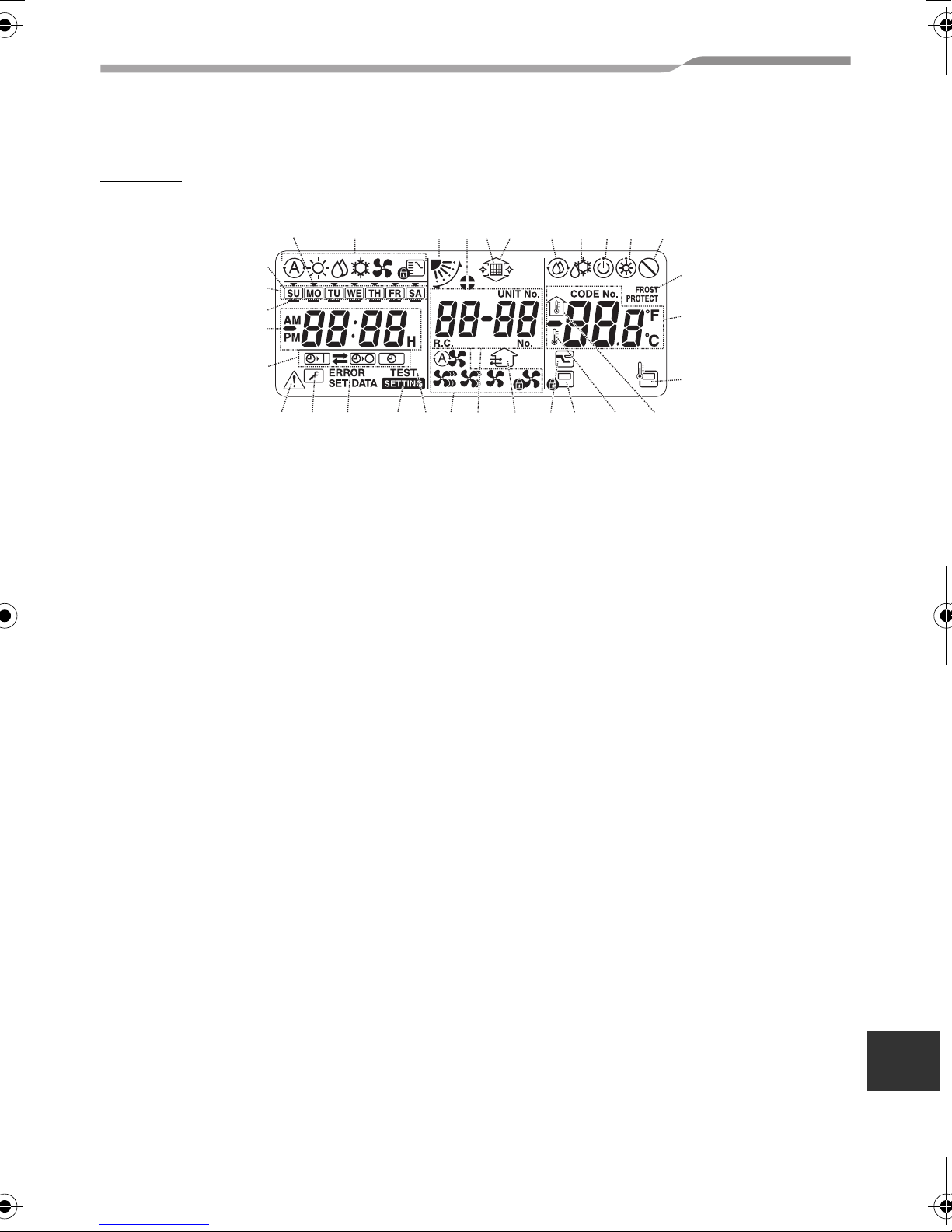
LCD area
All displays are shown lighted only for the purposes of description.
131 2 3 4 5 6 7 8 9 10
Owner’s Manual
30
29
28
27
26
22232425
21 20 19 18 17 16 15 14
1 Operation mode display
The selected operation mode is displayed.
2 Air direction
This indicates the air direction which has been
selected.
3 Fixed louvers
This appears when the louvers are fixed.
* It also appears when the remote controller
function has been selected.
4 Filter
This appears when it is time to inspect the
filter.
5 Grille up/down
This appears when the grille is goes up or
goes down.
6 Self-cleaning operation
This appears while self-cleaning is underway.
7 Defrosting
This appears while defrosting is underway
during a heating operation.
8 Ready
This display appears on some models.
9 Heating ready (indoor fan stops while
this is displayed)
This appears before a heating operation
starts or while defrosting.
11
12
13
10
No function
This appears when a button is pushed but
there is no corresponding function.
11
FROST PROTECT operation
This appears during a frost protection
operation.
12
Numeric display
This displays the numeric value of the
temperature, the numerical order of the
trouble history events or the code numbers
when the functions are set.
13
Remote control sensor
This appears when the remote control sensor
is used.
14
Indoor temperature
This appears when the intake temperature is
displayed on the numeric display.
15
Set temperature
This appears when the set temperature is
displayed on the numeric display.
16
Central control
This appears when key operation limits are
being enforced by the central controller or
other unit or when key operation limits have
been set in the program for the scheduled
operation currently being executed.
EN
–5–
4-EN
Page 6
Remote controller with weekly timer
17
Save operation
This appears while a save operation is being
set or executed.
18
Ventilation operation
This appears while the ventilation fan is
operating.
19
Numeric display
The numbers of the indoor units or numbers of
the scheduled operation programs are
displayed here.
20
Air speed display
This indicates the selected air speed.
21
TEST
This appears while a test run operation is
being performed.
Owner’s Manual
29
Days of the week display
30
Special holiday
This appears for a day of the week which has
been set as a special holiday.
31
Day arrow
This indicates the current day of the week or
day on which a program is set.
22
SETTING
This appears when the clock time, a program
or the timer is being set.
23
ERROR
This appears when there is an error in the
program setting input.
24
Servicing
This appears during servicing.
25
Inspect
This appears when trouble has occurred.
26
Timer function display
This indicates the function whose operation
has been scheduled when a scheduled
operation or timer operation has been set.
27
Numeric display
This indicates the present clock time, program
operation time or timer execution time.
28
Operation reservation
This appears for the days of the week on
which programs have been set.
5-EN
–6–
Page 7
Remote controller with weekly timer
Owner’s Manual
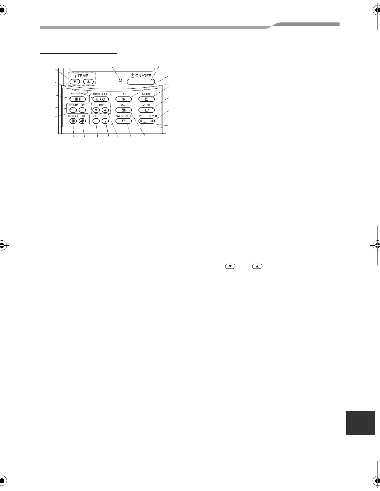
Button operation area
49
48
47
46
45
32
ON/OFF button
Shortly after this button is pushed, operation
starts, and operation stops shortly after the
button is pushed again.
33
FAN button
Use this to select the desired air speed mode.
34
MODE button
Use this to select the desired operation mode.
35
VENT button
Use this when a ventilation fan or other unit,
purchased on the market, has been
connected.
36
LOUVER button
Use this to select the louvers when setting the
air direction for each louver or when fixing the
louvers in place.
37
UNIT button
Use this to select the indoor unit to be
operated when operating a multiple number of
indoor units using one remote controller.
50
41
424344
40
39
38
32
33
34
35
36
37
42
SET button
Use this when entering the settings of the
program (for a scheduled operation or timer
operation) which is being set.
43
TEST button
Use this for servicing.
* This button is not normally used.
44
FLT.RESET button
Use this to reset (extinguish) the filter display.
45
DAY button
Use this to select the targeted day of the week
when setting the clock or setting a program.
46
PROGRAM button
Use this when starting and ending the
program settings for scheduled operations.
47
Grille button
Use this to raise or lower the grille.
48
SCHEDULE button
Use this when executing or releasing
scheduled operations or when selecting ON
or OFF for timer operations.
49
TEMP. buttons
Push and to set the temperature to
the desired value.
* These buttons are also used to raise or
lower the grille when the grille function is
used.
50
ON lamp
This lights during operation. It blinks when
trouble has occurred or when a protection
operation is performed.
38
SAVE button
Use this when performing save operations.
39
SWING/FIX button
Use this to select the desired air direction or
swing operation.
40
TIME buttons
Use this to set the clock or adjust the time
when the operating time is set.
41
CL button
Use this when clearing the setting of the
program (for a scheduled operation or timer
operation) which is being set.
–7–
EN
6-EN
Page 8
Remote controller with weekly timer
Owner’s Manual
3 SETTING THE CURRENT DAY OF THE WEEK
AND CLOCK TIME
• Set the current clock time and day of the
week.
• The day of the week and clock settings
can be performed whether the air
conditioner is running or shut down.
* The air conditioner continues to operate
(run) while the day of the week and
clock settings are being performed.
• The normal operation of the air conditioner
or a program for a scheduled operation
can be input even without performing the
day of the week and clock settings, but the
scheduled operation cannot be executed.
In order to execute scheduled operations,
the day of the week and clock must be set
without fail.
• Before this remote controller is shipped
from the factory, the initial setting (default)
of the 24-hour display is established for
the clock time display, but this can be
changed to the 12-hour (AM/PM) display.
* If you want to use the 12-hour time
display, refer to the “Selecting the
remote controller functions” section.
* In these instructions, the 24-hour
display is used in the figure and
descriptions.
Preparations
Turn on the ground fault interrupter.
• When the power is turned on, a dividing
line appears on the remote controller
display.
* For about a minute after the power has
been turned on, on the LCD
SETTING
screen blinks, and there will be no
response to the keys of the remote
controller even when they are pushed.
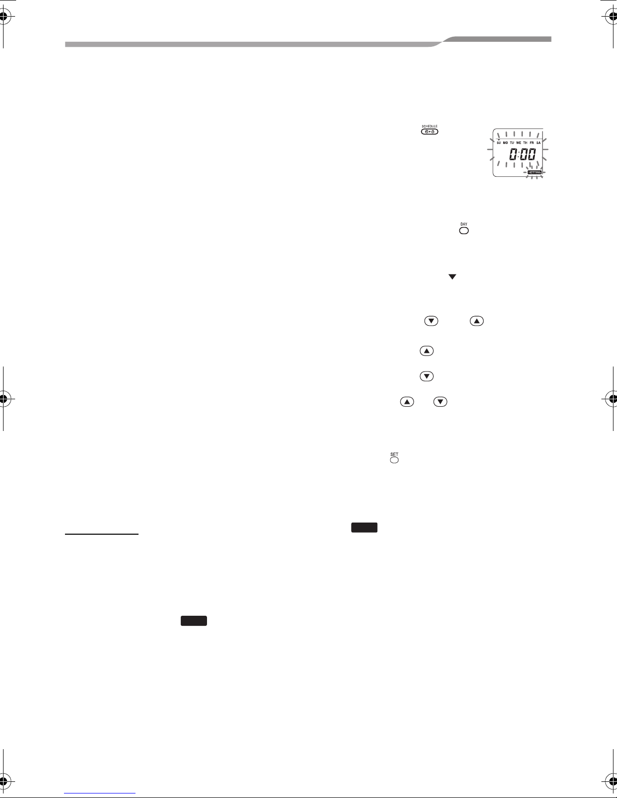
1 Hold down the button
(48) for at least 4
seconds.
• The display transfers to the
day of the week/clock
setting screen.
• The whole LCD display blinks.
<Blinks>
2 Repeatedly push the button (45),
and select the current day of the
week.
• Move the day arrow to the position
above the current day of the week.
• The LCD display continues to blink.
3 Push the TIME and buttons
(40), and select the current clock time.
• Each time the button (40) is pushed,
the clock is moved forward by one minute.
• Each time the button (40) is pushed,
the clock is moved back by one minute.
• When the
the clock is moved forward or back in 10minute increments.
• The LCD display continues to blink.
or button is held down,
4 Push the button (42) to return to the
original screen.
• As soon as the button is pushed, the clock
starts running. (Do this in synchronization
with a time signal.)
SETTING
• on the LCD screen goes off.
• After the clock has been set, the entire LCD
screen lights, but the colon (“:”) continues
to blink.
7-EN
–8–
Page 9

Remote controller with weekly timer
Owner’s Manual
4 CORRECT OPERATING PROCEDURES
Procedure for normal
operation
The functions will differ depending on the
model and system.
• Follow the steps below before using the
remote control system for the very first
time or when changing any of the settings.
• After the steps have been followed,
operation will commence using the
settings established simply by pushing the
button (32).
Preparations
Turn on the ground fault interrupter.
• When the power is turned on, a dividing
line appears on the remote controller
display.
* For about a minute after the power has
been turned on, on the LCD
screen blinks, and there will be no
response to the keys of the remote
controller even when they are pushed.
NOTE
• Do not turn off the ground fault interrupter
during the operating season of the
remote control system.
• After the remote control system has been
shut down for a prolonged period, turn on
the ground fault interrupter back on at
least 12 hours before its operation is to
be started.
SETTING
Starting operation
1 Push the button (32) to start
operation.
• The ON lamp lights, and the operation
details are displayed on the LCD screen.
2 Push the button (34), and select
the mode of operation.
• Each time this button is pushed, the
operation mode display changes in the
sequence shown below.
• Stop pushing the button when the symbol
corresponding to the desired mode of
operation lights.
Auto Heating
Fan Cooling Dry
3 Push the button (32) to shut
down operation.
• The ON lamp goes off, and the operation
details are cleared from the LCD screen.
(The frame lines remain displayed.)
• Before operation shuts down, the selfcleaning operation is commenced if the air
conditioner was run in the Auto (during
cooling), cooling or dry mode for 10 or
more minutes.
* For details on the self-cleaning
operation, refer to the “Self-cleaning
operations” section.
–9–
EN
8-EN
Page 10

Remote controller with weekly timer
Changing the air speed
1 Push the button (33), and select
the desired air speed.
• Each time the button is pushed, the air
speed display changes in the sequence
shown below.
• Stop pushing the button when the symbol
corresponding to the desired air speed
lights.
Auto air speed High air speed
Low air speed Medium air speed
* If, during heating, the rooms do not heat
up quickly at the low air speed setting,
change the setting to high or medium.
* The auto air speed cannot be selected
during fan operations.
Changing the temperature
1 Push the TEMP. and buttons
(49), and select the desired
temperature setting.
• When the button (49) is pushed, the
temperature on the numeric display goes
down; conversely, when the button
(49) is pushed, the temperature displayed
goes up.
• The temperature cannot be set during fan
operations.
Adjusting the air direction
The functions will differ depending on the
model and system.
• To increase the cooling or heating effect,
be sure to change the louver direction
between cooling and heating operations.
• The nature of air is to fall toward the floor
where it collects when it is cold and to rise
toward the ceiling where it collects when it
is warm.
Owner’s Manual
CAUTION
• For cooling operations, set the
louvers to the horizontal blow-out
position.
Performing cooling operations with the
louvers at the downward blow-out
position may cause condensation to
form around the air outlets and louver
surfaces and water may drip.
* For further details, refer to the
operating instructions of the air
conditioner.
Changing the air direction
1 During operation, push the
button (39), and select the desired air
direction.
• Each time the button is pushed, the air
direction display changes in the sequence
shown below.
• Stop pushing the button when the symbol
corresponding to the desired air direction
lights.
* Air directions 4 and 5 are not displayed
during cooling or dry operations.
* It may not be possible to set air direction
1 after the air direction has been at the
random setting.
If this is the case, wait 2 seconds, and
then push the button (39) again.
12345
Random SWING
Starting the louver swing motion
1 During operation,
push the button
(39), and select the
symbol shown on the
right.
• If the button is then pushed from the
downward blow-out position, the symbol
shown on the right lights for the air direction
display.
9-EN
–10–
Page 11

Remote controller with weekly timer
Owner’s Manual
Stopping the louver swing motion
1 While the louvers are swinging,
push the button (39) when
the louvers reach the desired
position.
• The symbol shown on the right lights for the
air direction display.
* The louvers will not stop at the
downward blowout position during a
cooling or dry operation.
Even when the button is pushed at the
downward blow-out position, the louvers
will stop swinging only after moving to
the third position from the top.
* Concerning the button (37)
• When a multiple number of indoor units
are being run using a single remote
controller, this button can be used to
select one indoor unit and set the air
direction of that unit.
• When the air direction is to be set for
each of the units, push the button
(37), and display the number of one of
the indoor units controlled as the group
on the numeric display. Change the air
direction for the indoor unit now
displayed.
• If no indoor unit number is indicated on
the numeric display, the same air
direction setting will apply to all the
indoor units.
Frost protection operation
(heating at 46°F (8°C))
The functions will differ depending on the
model and system.
• This is a heating operation function which
is specially designed for use in cold
regions where it will keep the indoor
temperature constant while you are out.
• To enable this function, an application
control setting is required. Consult your
dealer or a contractor with specialized
experience.
* For further details, refer to the operating
instructions of the air conditioner.
Setting the frost protection operation
1 Push the TEMP. button (49)
during a heating operation.
• Repeatedly push the button or hold it down
until “ ” appears on the numeric display.
2 Now hold down the TEMP. button
(49) for at least 4 seconds.
• When this button is pushed, what appears
on the numeric display changes from “ ”
to “ ”, and the display lights.
• The frost protection operation now starts.
Releasing the frost protection operation
1 Push the TEMP. button (49)
during the frost protection operation.
• When this button is pushed, the
display goes off, and what appears on the
numeric display changes from “ ” to
“”.
• A normal heating operation now starts. The
temperature setting is 64°F (18°C) so push
the TEMP. button (49), and select the
desired temperature setting.
–11–
EN
10-EN
Page 12

Remote controller with weekly timer
Owner’s Manual
Save operations
The functions will differ depending on the
model and system.
• During this operation, the maximum
current is restricted.
* For further details, refer to the operating
instructions of the air conditioner.
Initiating a save operation
1 During operation, push the
button (38).
• The save operation where the maximum
current is restricted starts, and the save
operation display lights.
2 To release the save operation, push
the button (38) again.
• The save operation display goes off,
and normal operation starts.
Self-cleaning operations
The functions will differ depending on the
model and system.
• When the air conditioner has stopped
operating after an auto (cooling), dry or
cooling operation, this function moves into
action to dry out the insides of the indoor
units using the fan operation so as to keep
the indoor units clean.
* For further details, refer to the operating
instructions of the air conditioner.
1 The self-cleaning operation starts
automatically when the air
conditioner was in the auto (cooling),
dry or cooling mode for at least 10
minutes before its operation is shut
down.
• The ON lamp goes off, the operation stop
display appears on the LCD screen, and
the self-cleaning operation display
lights.
• The duration of the self-cleaning operation
differs depending on the operation time
prior to shutdown.
Operation time
prior to shutdown
Under 10 minutes
10 or more minutes
but under an hour
1 hour or more 2 hours
Duration of
selfcleaning
operation
No self-cleaning
operation
1 hour
2 To stop the self-cleaning operation,
push the button (32) twice in
succession.
• The self-cleaning operation display
goes off, and the self-cleaning operation
ends.
11-EN
–12–
Page 13

Remote controller with weekly timer
Owner’s Manual
Grille operation procedure
The functions will differ depending on the
model and system.
* For further details, refer to the operating
instructions of the air conditioner.
Operation
1 Hold down the grille button (47)
for at least 4 seconds.
• The display transfers to the grille up/down
screen, and the indoor units stop
operating.
• The filter , grille up/down and
numeric display blink.
* The “no function” display appears
when the grille is not connected or the
control settings have not been
established correctly.
2 Push the button (37), and select the
indoor unit for which the grille is to be
set.
• Each time the button is pushed, the unit
number on the numeric display changes.
* The fan of the selected indoor unit starts
running, and the louver swings.
3 Push the TEMP. or button (49)
to move the up/down grille.
• When the button (49) is pushed, the
up/down grille goes down slowly;
conversely, when the button (49) is
pushed, the up/down grille goes up.
• If the up/down grille makes contact with an
obstacle while it is going down, it stops.
• Several seconds after the up/down grille
rises and is neatly stowed in the air intake,
the motor stops.
* The louver swings while the grille is
going up or down.
* When the grille is stowed in the panel,
this stowing operation is repeated 3
times to ensure that the grille is safely
stowed away.
4 Push the button (32) to stop the
up/down grille.
• The up or down movement of the up/down
grille now stops.
• If the button (32) is not pushed and
the grille continues to move down, the grille
will automatically stop when it has moved
down to the distance set.
* To change the movement from up to
down or vice versa, stop the up/down
grille movement first, and then make the
change.
5 Push the grille button (47).
• The grille operation mode is exited.
• The filter , grille up/down and
numeric display goes off, and blinks.
* While is blinking, there is no
response to the keys of the remote
controller even when they are pushed.
SETTING
Detailed settings
The functions will differ depending on the
model and system.
• For descriptions of the following settings,
refer to the operating instructions of the air
conditioner.
– Changing the swing type
– Fixing or releasing the louvers
– Changing the save operation settings
SETTING
–13–
EN
12-EN
Page 14

Remote controller with weekly timer
5 SCHEDULED OPERATIONS
Owner’s Manual
• Scheduled operations for a 1-week period
can be performed using this remote
controller.
• Eight (01 to 08) operations for each day of
the week can be set in a scheduled
operation program (item settings).
– The following items can be set in a
program:
a. Operation time
b. Operation start/stop
c. Operation mode
d. Temperature setting (frost protection)
e. Restriction on button operations
f. Save operation
• With a scheduled operation, the air
conditioner is operated at the set
operation time according to the program
which has been set.
• The operation time can be set in 1-minute
increments.
* Restriction on button operations
This function cancels the button
operations while a scheduled operation
is being executed. To use this function,
refer to the “Selecting the remote
controller functions” section and
change the settings before proceeding
with the program settings described
below. The initial (factory) setting calls
for no restriction on the button
operations.
* Save operation
The save operation function is not
provided for some models and systems.
To find out whether the function is
provided, consult your dealer or a
contractor with specialized experience.
* Concerning the “Continue xx” setting
The “Continue” setting can be
established for the operation ON/OFF,
operation mode and temperature
setting items. This setting causes the
current operation modes of the indoor
units to be continued.
* “Continue” is set on the initial screen for
each item of each program number so
in the example of the operation given
above there is no need to input anything
for the operation ON/OFF and
operation mode items.
* This function does not work if the “timer
operation function” or “no timer
function” has been selected by
following the steps set forth in the
“Selecting the remote controller
functions” section.
How to set up the operation
programs
• Perform the steps below to set up a
scheduled operation program (item
settings).
* Programs can be set up whether the air
conditioner is running or shut down.
* While these steps are being taken, an
air conditioner which is operating
continues to operate.
1 Push the button (46).
• The display transfers to the program input
screen.
• The entire LCD screen starts blinking.
2 Push the button (45).
• Repeatedly push the button to move the
day arrow to the position above the day
of the week when the scheduled operation
is to be executed.
3 Push the button (42).
• Set the day of the week when the
scheduled operation is to be executed.
• The days of the week display and the day
arrow stop blinking and light up.
13-EN
–14–
Page 15

Remote controller with weekly timer
Owner’s Manual
4 Push the button (37).
• Each time the button is pushed, the
number on the numeric display changes in
the following sequence.
• Stop pushing the button when the number
to be programmed blinks on the display.
* For the items inside the square
parentheses, refer to the “Editing the
operation programs” section.
5 Push the button (42).
• The program number on the numeric
display stops blinking and lights up.
6 Push the TIME and buttons
(40).
• Set the operation time. This time must be
input.
• The steps taken are the same as for setting
the clock.
* After setting the time, there is no need to
push the button (42). All the items will
be entered together in step 8.
7 Set what is to be operated at the time
which was set in step 6.
* The settings can be established in any
sequence.
The functions will differ depending on the
model and system.
1. Selecting and setting operation/stop
Each time the button (48) is pushed, what
appears on the timer function display changes
in the following sequence. Stop pushing the
button when the desired operation blinks on
the display.
Operation mode Fan Cooling
(No display)
Auto Heating Dry
3. Setting the temperature
Each time the TEMP. and buttons
(49) are pushed, what appears on the numeric
display changes in the following sequence.
Stop pushing the buttons when the target
temperature to be set blinks on the display.
or
Push 4 seconds
or more
Frost protection
operation
Push 4 seconds or more
4. Setting the restriction on the button operations
• Each time the button (34) is pushed
while the button (43) is held down, the
central control display changes from off to
blinking or vice versa.
To place the restriction on the button
operations, ensure that the display is
blinking.
* The button (32), button
(34) and TEMP. and buttons
(49) are the buttons whose operation
will be restricted by this setting.
For further details, refer to the “Selecting
the remote controller functions” section.
(No display)
Operation
continue
2. Selecting and setting the operation mode
Each time the button (34) is pushed,
what appears on the operation mode display
(1) changes in the following sequence. Stop
pushing the button when the operation mode
blinks on the display.
Operation
stop
Operation
start
–15–
EN
14-EN
Page 16

Remote controller with weekly timer
Owner’s Manual
5. Setting the save operation
Each time the button (38) is pushed, the
numeric display and save operation display
change in the following sequence. Stop
pushing the button when the desired save
operation mode (mode 0 to 3) blinks on the
display.
Mode 0 Mode 1 Mode 2 Mode 3
Save operation
mode
Mode 0 No save operation
Mode 1
Mode 2
Mode 3 Compressor shutdown
Description
Save operation with 75%
upper limit
Save operation with 50%
upper limit
8 Push the button (42), and enter all
the items in steps I to V above and the
operation time together.
The display of all the setting items changes
from blinking to lighted.
9 In addition:
1. To input the settings into the different
program number for the same day of the
week, repeat the operations from step 4.
2. To move to a different day of the week and
input the program, repeat the operations
from step 2.
10
Finally, push the button (46) to
return to the original screen.
• An underbar is displayed under the
selected day of the week.
Example of setting up an
operation program
Example of program input
For program 01 for Wednesday, “7:00”,
“ON”, “heating”, “77°F (25°C)”, “restriction on
key operation enabled”, “save operation” and
“mode 1” will be set.
• Initial screen (clock setting/operation stop)
0
• Push the button (46), and
transfer the display to the input
screen.
• On the input screen, the entire
display blinks.
1
• Push the button (45), and move
the day arrow to the position
above “WE”.
2
• Push the button (42), and enter
the day of the week.
• The days of the week display and
the day arrow stop blinking and
light up.
3
• Repeatedly push the button (37),
and display the number of the
program which is to contain the
settings on the numeric display.
4
15-EN
–16–
Page 17

Remote controller with weekly timer
Owner’s Manual
5
6
7
• Push the button (42), and enter
the program number.
• The numeric display stops blinking
and lights up.
• Push the TIME and buttons
(40), and set the operation time.
• If the buttons are held down for four
or more seconds, the time can be
moved forward or back in 10-minute
increments.
1. Selecting and setting operation/stop
Push the button (48) until
blinks on the display.
2. Selecting and setting the operation
mode
Push the button (34) until
blinks on the display.
3. Setting the temperature
Push the TEMP. and buttons
(49) until “77” blinks on the numeric
display.
4. Setting the restriction on the button
operations
Push the button (34) while
holding down the button (43) until
blinks on the display.
5. Setting the save operation
Push the button (38) until
blinks on the display.
8
• Finally, when the button (46) is
pushed, goes off, and the
original screen is restored.
SETTING
9
• An underbar is displayed under the
selected day of the week.
Scheduled operation setup
How to execute scheduled operations
• On the screen of the remote controller
whose power has been turned on, check
that the current day of the week and clock
time are set accurately.
Scheduled operations cannot be executed
while the days of the week display, the day
arrow and numeric display are still
blinking.
• Set at least one operation program.
Check that at least one operation
reservation display is indicated below
the days of the week on the remote
controller screen.
1 Push the button (48).
• Although first extinguished on the
timer function display, the symbol
shown on the right now starts blinking.
2 Push the button (42) within 5
seconds of completing step
• The symbol on the timer function display
stops blinking and lights.
1.
• Push the button (42) to enter the
operation settings.
• With the exception of , all the
displays stop blinking and light up.
SETTING
How to release a scheduled operation
1 Push the button (48).
• The symbol on the timer function display
changes from the lighted status to blinking.
2 Push the button (41) within 5
seconds of completing step
• The symbol on the timer function display
stops blinking and goes off.
–17–
EN
1.
16-EN
Page 18

Remote controller with weekly timer
Owner’s Manual
Error displays
• Trouble may be to blame if the ERROR
display remains lighted for 3 seconds
while a scheduled operation is being
executed or while a scheduled operation
program is being input. Check for trouble,
and remedy it.
1 When the button (42) was pushed
while a scheduled operation was
being executed:
• The current day of the week and/or current
clock time have not been set. Proceed with
the clock setting operation.
• No programs have been set. Input the
operation program.
2 When the button (42) was pushed
while a program was being input:
• One setting time overlaps another setting
time.
Change one of the setting times.
• Display the number of the program to be
checked, and check the program’s
settings.
* Unless the button (42) is pushed, the
key operations are canceled, in which
case the program settings will remain
unchanged.
5 After completing the check, push the
button (46) to return to the original
screen.
Editing the operation programs
(instructions for copying)
• When setting the operation programs, the
already programmed settings for another
days of the week can be copied for an
specially designated day of the week.
* The program settings can be copied
whether the air conditioner is running or
shut down.
Copying the program settings
Program check operation
• Programs are checked using the program
input screen.
1 Push the button (46).
• The display transfers to the program input
screen.
• The entire LCD screen blinks.
2 Push the button (45).
• Repeatedly push the button until the day
arrow moves to the position above the
day of the week whose program is to be
checked.
3 Push the button (42).
• Enter the day of the week whose program
is to be checked.
• The days of the week display and day
arrow stop blinking and light up.
4 Push the button (37).
• Each time this button is pushed, the
program number and editing type are
scrolled forward in sequence on the
numeric display.
1 Push the button (46).
• The display transfers to the program input
screen.
• The entire LCD screen blinks.
2 Push the button (45).
• Repeatedly push the button until the day
arrow moves to the copy source day of
the week.
3 Push the button (42).
• Enter the copy source day of the week.
• The days of the week display and day
arrow stop blinking and light up.
4 Push the button (37).
• Repeatedly push this button
until “PG-CP” (shown right)
appears on the numeric
display.
* PG-CP ..... P
ROGRAM-COPY
5 Push the button (42).
• The “ ” display stops blinking and
lights up.
• The day of the week where the day arrow
is lighted serves as the copy source.
17-EN
–18–
Page 19

Remote controller with weekly timer
Owner’s Manual
6 Again push the button (45).
• Repeatedly push the button until the day
arrow moves to the copy destination day
of the week.
• The day arrow blinks while the copy
destination is being selected.
7 Push the button (42).
• The settings of the copy source day of the
week are copied into the copy destination
day of the week.
• The blinking of the day arrow displayed
for the copy destination day of the week
changes to the lighted operation
reservation display.
* Copying involves overwriting any
existing settings.
Bear in mind that the original setting of
the copy destination will be deleted
when the button (42) is pushed.
8 To continue copying, repeat steps 4
7.
to
9 Finally, push the button (46) to
return to the original screen.
3 Push the button (42).
• Enter the day of the week whose programs
are to be cleared.
• The days of the week display and day
arrow stop blinking and light up.
4 Push the button (37).
• Repeatedly push this button
until “PG-CL” (shown right)
appears on the numeric display.
* PG-CL ...... P
ROGRAM-CLEAR
5 Push the button (42).
• The settings of all the programs which
have been set and displayed for the day of
the week are cleared (deleted), and the no
program set status blinks on the screen.
* Bear in mind that cleared settings
cannot be restored.
6 To continue clearing, repeat steps 2
5.
to
7 Finally, push the button (46) to
return to the original screen.
How to clear individual programs on the
same day of the week
Editing the operation programs
(instructions for clearing)
• Operation programs which have been set
can be cleared (deleted) in two ways.
1. All the programs for a specific day of the week
can be cleared.
2. A specific program on a specific day of the
week can be cleared.
* The program settings can be cleared whether
the air conditioner is running or shut down.
How to clear the program settings
How to clear the programs for a specific
day of the week
1 Push the button (46).
• The display transfers to the program input
screen.
• The entire LCD screen blinks.
2 Push the button (45).
• Repeatedly push the button until the day
arrow moves to the day of the week
whose programs are to be cleared.
1 Push the button (46).
• The display transfers to the program input
screen.
• The entire LCD screen blinks.
2 Push the button (45).
• Repeatedly push the button until the day
arrow moves to the day of the week for
which a program to be cleared has been
set.
3 Push the button (42).
• Enter the day of the week for which the
program to be cleared has been set.
• The days of the week display and day
arrow stop blinking and light up.
4 Push the button (37).
• Repeatedly push this button until the
number of the program to be cleared
appears on the numeric display.
• The program number displayed blinks.
EN
–19–
18-EN
Page 20

Remote controller with weekly timer
Owner’s Manual
5 Push the button (42).
• Enter the number of the program to be
cleared.
• The program number on the numeric
display blinks.
6 Push the button (41).
• The settings for the program number on
the numeric display are cleared (deleted),
and the no program set status blinks on the
screen.
* Bear in mind that cleared settings
cannot be restored.
7 To continue clearing, repeat steps 2
6.
to
8 Finally, push the button (46) to
return to the original screen.
Editing the operation programs
(instructions for special
holidays)
• A “special holiday” is a day of the week on
which the scheduled operations set for
that day of the week can be temporarily
canceled. (The program remains stored in
the memory.)
• When the day of the week set as a special
holiday has passed, the special holiday
setting is released, and the air conditioner
operates as per the original program
starting from the following week.
• Special holiday settings can be
established for any day up to a week
ahead starting from the current day of the
week. When a special holiday has been
set for the current day of the week, the
setting starting from the next program time
after the set time will be canceled.
• The special holiday setting cannot be
established for any day of the week which
has no program settings.
* The special holiday setting can be
established whether the air conditioner
is running or shut down.
How to establish the special holiday setting
1 Push the button (46).
• The display transfers to the program input
screen.
• The entire LCD screen blinks.
2 Push the button (45).
• Repeatedly push the button until the day
arrow moves to the day of the week
which is to be set as a special holiday.
3 Push the button (42).
• Enter the day of the week which is to be set
as a special holiday.
• The days of the week display and day
arrow stop blinking and light up.
4 Push the button (37).
• Repeatedly push this button
until “PG-HL” (shown right)
appears on the numeric display.
* PG-HL ...... P
ROGRAM-HOLIDAY
5 Push the button (42).
• The special holiday display blinks at the
day of the week which has now been set as
a special holiday.
6 To continue with another setting,
repeat steps 2 to 5.
7 Finally, push the button (46) to
return to the original screen.
• The special holiday display above the
day of the week set stops blinking and
lights up.
How to cancel the special holiday setting
1 Perform steps 1 to 4 in “How to
establish the special holiday setting”
for the day of the week whose special
holiday setting is to be canceled.
2 Push the button (42).
• The special holiday display over the day
of the week set changes from lighted to
blinking.
3 Finally, push the button (46) to
return to the original screen.
• The special holiday display above the
day of the week set stops blinking and goes
off.
19-EN
–20–
Page 21

Remote controller with weekly timer
6 TIMER OPERATIONS
Owner’s Manual
• Before this remote controller is shipped
from the factory, the schedule timer
operation function is set as an initial
setting (default), but the count-down timer
operation function can be selected
instead.
* Users who want the timer operation
function should refer to the “Selecting
the remote controller functions” section.
* Bear in mind that if the timer operation
function has been selected, the
scheduled operation function cannot be
used.
• The three following functions can be
selected by the timer operation function:
OFF timer:
Operation is shut down when the set time
is reached.
Repeated OFF timer:
Every time operation is started, it is shut
down after the set duration.
ON timer:
Operation is started when the set time is
reached.
* The maximum time which can be set is
168 hours (7 days).
Timer operations
How to execute timer operations
1 During operation, push the
button (48), and select the timer
operation which is to be set.
• The display and numeric display
blink, and the timer function display lights.
• Each time the button is pushed, what
appears on the timer function display
changes in the following sequence.
• Stop pushing the button when the desired
operation lights up on the display.
SETTING
No timer
(No display)
2 Push the TIME and buttons
(40), and select the set time.
• Each time the button (40) is pushed,
the set time is moved forward in half-hour
(30-minute) increments. If the set time is
more than one day (24 hours) ahead, it is
moved forward in 1-hour increments. The
upper limit is 7 days (168 hours) ahead.
The numbers representing any set time
from 0.5 hour to 23.5 hours appear on the
numeric display.
For a set time more than 24 hours ahead,
the number of days and time are indicated.
• Each time the button (40) is pushed,
the set time is moved back in half-hour (30minute) increments (from 0.5 hour to 23.5
hours) or in 1-hour increments (from 24
hours to 168 hours).
Example of remote controller display
• When the set time is 23.5 hours ahead
• When the set time is 34 hours ahead
“1d” = 1 day = 24 hours
“10H” = 10 hours
Total = 34 hours
3 Push the button (42).
• The numeric display stops blinking and
lights up, and the timer function display
changes to blinking from its lighted status.
• The display goes off.
SETTING
* When the ON timer function is set, the
operation of the air conditioner is shut
down. This means that apart from the
lighted numeric display and blinking
timer function display, all other displays
go off.
How to cancel a timer operation
1 Push the button (41) during the
timer operation.
• The timer function display and numeric
display go off.
* A timer operation can be canceled while
the timer operation is being set or
executed.
EN
OFF timer Repeated
OFF timer
ON timer
–21–
20-EN
Page 22

Remote controller with weekly timer
7 TROUBLESHOOTING
Owner’s Manual
Before requesting repair work
Check out the following points before
requesting repair work.
The scheduled operation is not
performed even though the set time is
reached.
• The scheduled operation has not been
set.
• A special holiday has been set.
The current clock time setting is blinking.
• There has been a prolonged power
outage. Re-set the current clock time and
current day of the week.
There is no response when the keys are
operated.
• The restriction has been set for the key
operations.
Check the program.
The clock is not displayed when the
power is turned on.
• The timer operation function or follower
remote controller has been set.
• The setting for not displaying the clock has
been established.
CAUTION
If the problem persists even after checking
out the above points, stop operating the air
conditioner, set the ground fault interrupter
to off, and give the model number and
details of the symptoms to your dealer. Do
NOT attempt to remedy the problem
yourself due to the dangers involved.
Trouble diagnosis
Checks and inspections
• When trouble has occurred in the air
conditioner, an inspection code and the
number of the indoor unit concerned blink
on the numeric display.
Inspection code Address of indoor unit
where the trouble has
occurred
• Inspection codes are displayed only
during operation.
• If the display has gone off, check the
trouble by following the steps in “Checking
the trouble history” below.
Checking the trouble history
• When trouble has occurred in the air
conditioner, the trouble history can be
checked by following the steps below. (Up
to four events are stored in the trouble
history.)
• The trouble history can be checked
whether the air conditioner is running or
shut down.
1 Push the button (42) and button
(43) together for at least 4 seconds.
• The numeric displays blink, and the
servicing display and inspect display
light.
Inspection code
Numerical order of
trouble history events
21-EN
Address of indoor unit where
the trouble has occurred
–22–
Page 23

Remote controller with weekly timer
2 Push the TEMP. or button
(49).
• Each time one of these buttons is pushed,
the trouble history events are displayed in
numerical order.
• The “01” code on the numeric display
indicates the latest event, and “04” the
earliest event.
* Do not push the button (41) since all
the trouble history events of the indoor
units will be deleted.
3 After checking the events, push the
button (43) to return to the original
screen.
Concerning trouble occurring in the
remote controller
“ ”, “ ” and “ ” blink at the same
time.
• This means that trouble has occurred on
the remote controller’s circuit board.
Contact your dealer.
• Normal air conditioner operations are still
possible, but no scheduled operations can
be performed.
Owner’s Manual
–23–
EN
22-EN
Page 24

Remote controller with weekly timer
Owner’s Manual
8 SELECTING THE REMOTE CONTROLLER
FUNCTIONS
• Change the settings of the remote
controller functions as required by taking
the steps below.
How to change the remote controller
functions
1 While operation is shut down, push
the button (43) and button (48)
together for at least 4 seconds.
• The numeric displays and display
blink, and the fixed louvers display lights.
SETTING
2 Push the TEMP. and buttons
(49).
• Repeatedly push the buttons until the
setting to be changed blinks on the display.
3 Push the TIME and buttons
(40).
• Repeatedly push the buttons until the
setting to be changed blinks on the display.
4 Push the button (42). Then push
the button (43) to return to the
original screen.
• When the button (42) is pushed, the
numeric displays and display stop
blinking and light up, and when the
button (43) is pushed again, they go off.
SETTING
Items to be set
• 24-hour/12-hour display setting <code
No.10>
– The 24-hour display or 12-hour (AM/
PM) display can be selected for the
clock which is displayed on the remote
controller.
– This item’s selection is also reflected on
the clock displayed on the clock setting
screen and program input screen.
Setting Description
0000: 24-hour display (factory
setting)
0001: 12-hour (AM/PM) display
• Restriction on button operations <code
No.12>
This item sets the range of the restriction
placed on the button operations which can
be applied while scheduled operations are
being performed.
Setting: 0000 (factory setting)
▼ Code No.12
O: Can be operated.
X: Cannot be operated.
Setting [ON/OFF] [MODE] [TEMP.]
0000 O O O
0001 X O X
0002 X X X
0003 O X X
0004 O X O
23-EN
–24–
Page 25

Remote controller with weekly timer
Owner’s Manual
• Display/non-display of clock <code
no.13>
This item selects and sets whether the day
of the week and clock time are to be
displayed.
Setting: 0000 (factory setting)
▼ Code No.13
O: Display
X: No display
Scheduled operation
underway
Setting
0000OOOO
0001 X X X X
0002 O O X X
0003 O X X X
0004 O O O X
0005 O X O X
Air
conditioner
now
operating
Air
conditioner
now shut
down
Scheduled operation in
standby
Air
conditioner
now
operating
Air
conditioner
now shut
down
• Selection of operation when power is
restored after a power outage <code
No.14>
This item selects the operation to be
performed when power is restored after a
power outage occurred during a
scheduled operation.
0000: No operations are performed when
the power is restored, and the scheduled
operation is resumed as soon as the
program time is reached after the power
has been restored. (When the power is
restored, the scheduled operation is
based on the operation of the indoor
units.)
0001: If there was a programmed
operation during the power outage, that
operation is performed when the program
is resumed. If there is no programmed
operation or if the “Continue xx” setting is
in place, the operation prior to the power
outage is resumed.
Selecting the functions using the DIP
switches of the remote controller
• The following functions can be selected
using the DIP switches on the remote
controller’s circuit board.
Setting procedure
• Open the back cover of the remote
controller, and select the functions using
the DIP switches located at the bottom left
of the circuit board.
• After establishing the settings, turn the
ground fault interrupter off and then back
on.
Setting items
• Remote controller header/follower setting:
Bit 1
When operating the air conditioner using
two remote controllers, set one of the
controls to be the follower.
* Set the remote controller used as the
schedule timer to be the header.
• Operation function setting: Bit 2
One of the following three operation
functions can be selected and set.
1.Scheduled operation function
2.Timer operation function
3.No scheduled or timer operation
function
[DIP switches] (factory settings)
Bit
ON
OFF
Bit 1 Bit 2 Bit 3 Bit 4
ON: Timer
ON: Follower
OFF: Header
operation
OFF: No
function
ON: Timer
operation
OFF:
Scheduled
operation
——
——
EN
–25–
24-EN
Page 26

EH99677901
 Loading...