

Toshiba CARRIER RAV-SP180CT-UL, CARRIER RAV-SP300CT-UL, CARRIER RAV-SP240CT-UL, CARRIER RAV-SP360CT-UL, CARRIER RAV-SP420CT-UL Installation Manual
Page 1
AIR CONDITIONER (SPLIT TYPE)
Installation Manual
Indoor Unit
Model name:
Under Ceiling Type
RAV-SP180CT-UL
RAV-SP240CT-UL
RAV-SP300CT-UL
RAV-SP360CT-UL
RAV-SP420CT-UL
Not accessible to the general public
Vente interdite au grand public
Installation Manual
Air conditioner
Manuel d’installation
Climatiseur
(Split type) 1
(Type split) 33
English
Français
Page 2
Under Ceiling Type
Please read this Installation manual carefully before installing the Air Conditioner.
• This Manual describes the installation method of the indoor unit.
• For installation of the outdoor unit, follow the Installation Manual attached to the outdoor unit.
Installation Manual
ADOPTION OF NEW REFRIGERANT
This Air Conditioner uses R410A an environmentally friendly refrigerant.
Contents
1 ACCESSORY PARTS. . . . . . . . . . . . . . . . . . . . . . . . . . . . . . . . . . . . . . . . . . . . . . . . . . . 2
2 PRECAUTIONS FOR SAFETY. . . . . . . . . . . . . . . . . . . . . . . . . . . . . . . . . . . . . . . . . . . . 3
3 SELECTION OF INSTALLATION PLACE . . . . . . . . . . . . . . . . . . . . . . . . . . . . . . . . . . . 5
4 REFRIGERANT PIPING AND EVACUATING . . . . . . . . . . . . . . . . . . . . . . . . . . . . . . . 11
5 DRAIN PIPING WORK . . . . . . . . . . . . . . . . . . . . . . . . . . . . . . . . . . . . . . . . . . . . . . . . . 14
6 ELECTRICAL CONNECTION. . . . . . . . . . . . . . . . . . . . . . . . . . . . . . . . . . . . . . . . . . . . 16
7 APPLICABLE CONTROLS. . . . . . . . . . . . . . . . . . . . . . . . . . . . . . . . . . . . . . . . . . . . . . 21
8 TEST RUN. . . . . . . . . . . . . . . . . . . . . . . . . . . . . . . . . . . . . . . . . . . . . . . . . . . . . . . . . . . 27
9 TROUBLESHOOTING . . . . . . . . . . . . . . . . . . . . . . . . . . . . . . . . . . . . . . . . . . . . . . . . . 29
1-EN
–1–
Page 3
Under Ceiling Type
Installation Manual
1 ACCESSORY PARTS
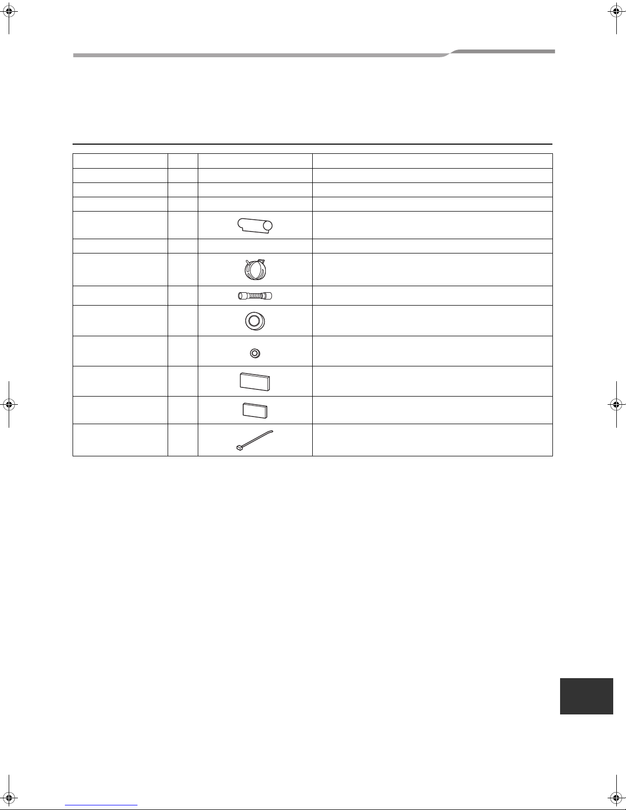
Accessory parts
Part name Q’ty Shape Usage
Owner’s Manual 1 – –
Installation Manual 1 This manual –
Installation pattern 1 – Drawing-out port of hanging bolt pipe
Thermal insulation pipe 2 For thermal insulation of pipe connecting section
Washer 4 3/8” (M10) × Ø1.0” (25 mm) For holding down unit
Hose band 2 For connecting drain pipe
Drain hose 1 For connecting drain pipe
Bushing Ø2.2” (Ø56) 1 For protection of edge at hole for remote control wires
Bushing Ø1.1” (Ø28) 1 For sealing the back side conduit hole
Thermal insulator 1
Thermal insulator of top
plate
Banding band 2 For prevention of open of drain hose thermal insulator
1
For thermal insulation of drain hose
(0.4” - thickness × 7.9” × 7.9” (10 - thickness × 200 × 200 mm))
For upper pipe hole of indoor unit
(0.2” - thickness × 5.1” × 6.3” (6 - thickness × 130 × 160 mm))
–2–
EN
2-EN
Page 4
Under Ceiling Type
Installation Manual
2 PRECAUTIONS FOR SAFETY
Installing, starting up, and servicing air--conditioning equipment can be hazardous due to system pressures,
electrical components, and equipment location (roofs, elevated structures, etc.).
Only trained, qualified installers and service mechanics should install, start--up, and service this equipment.
Untrained personnel can perform basic maintenance functions such as cleaning heat exchanger. All other
operations should be performed by trained service personnel.
When working on the equipment, observe precautions in the literature and on tags, stickers, and labels attached
to the equipment.
Follow all safety codes.Wear safety glasses and work gloves. Keep quenching cloth and fire extinguisher nearby
when brazing. Use care in handling, rigging, and setting bulky equipment.
Read these instructions thoroughly and follow all warnings or cautions included in literature and attached to the
unit. Consult local building codes and National Electrical Code (NEC) for special requirements. Recognize safety
information. This is the safety--alert symbol . When you see this symbol on the unit and in instructions or
manuals, be alert to the potential for personal injury.Understand these signal words: DANGER, WARNING, and
CAUTION. These words are used with the safety--alert symbol.
DANGER identifies the most serious hazards which will result in severe personal injury or death. WARNING
signifies hazards which could result in personal injury or death. CAUTION is used to identify unsafe practices which
may result in minor personal injury or product and property damage. NOTE is used to highlight suggestions which
will result in enhanced installation, reliability, or operation.
WARNING
• Ask an authorized dealer or qualified installation professional to install (including moving)/maintain the air
conditioner.
Inappropriate installation may result in water leakage, electric shock or fire.
• Be sure to connect ground wire. (grounding work)
Incomplete grounding cause an electric shock.
Do not connect ground wires to gas pipes, water pipes, lightning rods or ground wires for telephone wires.
• Turn off the circuit breaker before attempting any electrical work.
Make sure all circuit breaker is off. Failure to do so may cause electric shock.
• Install the refrigerant pipe securely during the installation work before operating the air conditioner.
If the air conditioner is operated with the valve open and without the refrigerant pipe, the compressor sucks air and
the refrigeration cycle is overpressurized, which may cause a burst or injury.
• When moving the air conditioner for the installation into another place, be very careful not to enter any
gaseous matter other than the specified refrigerant into the refrigeration cycle.
If air or any other gas is mixed in the refrigerant, the gas pressure in the refrigeration cycle becomes abnormally high
and it resultingly causes pipe burst and injuries on persons.
• Perform installation work properly according to the Installation Manual.
Inappropriate installation may result in water leakage, electric shock or fire.
• When the air conditioner is installed in a small room, provide appropriate measures to ensure that the
concentration of refrigerant leakage occur in the room does not exceed the critical level.
• Install the air conditioner securely in a location where the base can sustain the weight adequately.
• Perform the specified installation work to guard against an earthquake.
If the air conditioner is not installed appropriately, accidents may occur due to the falling unit.
• If refrigerant gas has leaked during the installation work, ventilate the room immediately.
If the leaked refrigerant gas comes in contact with fire, noxious gas may generate.
• After the installation work, confirm that refrigerant gas does not leak.
If refrigerant gas leaks into the room and flows near a fire source, such as a cooking range, noxious gas might
generate.
• Electrical work must be performed by a qualified electrician in accordance with the Installation Manual. Make
sure the air conditioner uses an exclusive power supply.
An insufficient power supply capacity or inappropriate installation may cause fire.
• Use the specified wires for wiring connect the terminals securely fix.
To prevent external forces applied to the terminals from affecting the terminals.
3-EN
–3–
Page 5
Under Ceiling Type
• Conform to the regulations of the local electric company when wiring the power supply.
Inappropriate grounding may cause electric shock.
• For the refrigerant recovery work (collection of refrigerant from the pipe to the compressor), stop the
compressor before disconnecting the refrigerant pipe.
If the refrigerant pipe is disconnected while the compressor is working with the valve open, the compressor sucks air
and the refrigeration cycle is overpressurized, which may cause a burst or injury.
Installation Manual
CAUTION
• THIS AIR CONDITIONER ADOPTS THE NEW HFC REFRIGERANT (R410A) WHICH DOES NOT DESTROY
OZONE LAYER.
• The characteristics of R410A refrigerant are ; easy to absorb water, oxidizing membrane or oil, and its pressure is
approx. 1.6 times higher than that of refrigerant R22. Accompanied with the new refrigerant, refrigerating oil has also
been changed. Therefore, during installation work, be sure that water, dust, former refrigerant, or refrigerating oil does
not enter the refrigerating cycle.
• To prevent charging an incorrect refrigerant and refrigerating oil, the sizes of connecting sections of charging port of
the main unit and installation tools are changed from those for the conventional refrigerant.
• Accordingly the exclusive tools are required for the new refrigerant (R410A).
• For connecting pipes, use new and clean piping designed for R410A, and please care so that water or dust does not
enter.
• Tighten the flare nut with a torque wrench in the specified manner.
Excessive tightening of the flare nut may cause a crack in the flare nut after a long period, which may result in
refrigerant leakage.
• Wear heavy gloves during the installation work to avoid injury.
• The installation fuse must be used for the power supply line of this conditioner.
–4–
EN
4-EN
Page 6
Under Ceiling Type
Installation Manual
3 SELECTION OF INSTALLATION PLACE
WARNING
• Install the air conditioner at enough strong place
to withstand the weight of the unit.
If the strength is not enough, the unit may fall down
resulting in injury.
• Install the air conditioner at a height 8’ (2.4 m) or
more from the floor.
If you insert your hands or others directly into the unit
while the air conditioner operates, it is dangerous
because you may contact with revolving fan or active
electricity.
CAUTION
• Do not install the air conditioner in a location
subject to a risk of exposure to a combustible gas.
If a combustible gas leaks and stays around the unit,
a fire may occur.
Upon approval of the customer, install the air
conditioner in a place that satisfies the
following conditions.
• Place where the unit can be installed horizontally.
• Place where a sufficient servicing space can be
ensured for safety maintenance and check.
• Place where drained water will not cause any
problem.
Avoid installing in the following places.
• Place exposed to air with high salt content (seaside
area), or place exposed to large quantities of sulfide
gas (hot spring).
(Should the unit be used in these places, special
protective measures are needed.)
• Place exposed to oil, vapor, oil smoke or corrosive
gas.
• Place where organic solvent is used nearby.
• Place close to a machine generating high frequency.
• Place where the discharged air blows directly into
the window of the neighbor house. (Outdoor unit)
• Place where noise of the outdoor unit is easily
transmitted.
(When install the outdoor unit on the boundary with
the neighbor, pay due attention to the level of noise.)
• Place with poor ventilation. (Before air ducting work,
check whether value of fan speed, static pressure
and duct resistance are correct.)
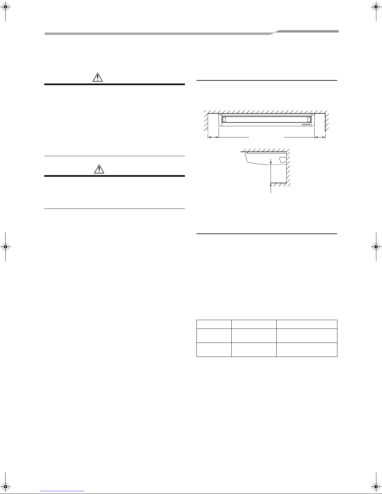
Installation space
Secure the specified space in the figure for
installation and servicing.
Unit: in (mm)
9.8” (250)
or more
19.7” (500) or more
9.8” (250)
or more
Height of ceiling
Set the installable height of the ceiling within 13’1” (4
m), otherwise the air distribution will become poor.
If height of ceiling exceeds 11’6” (3.5 m), hot air
becomes difficult to reach the floor surface, and then
the change of setup of high ceiling is necessary.
For the change method of high ceiling, refer to the
application control, “In case of installation to high
ceiling” and “In case of incorporating filter sold
separately” in this Manual.
List of installable ceiling height
Setup data
0000
0001 High ceiling 1
According to the conditions of installation, setup time of
turning-on of filter sign (notification of filter cleaning) of
the remote control can be changed.
When it is difficult to warm up the room due to
installation place or structure of the room, the detection
temperature of heating can be raised.
For change the setup time, refer to the application
control, “Change of filter sign turning-on time” and
“How to increase the heating effect” in this Manual.
Standard
(Factory default)
11’6” (3.5 m) or less
more than 11’6” (3.5 m)
up to 13’1” (4.0 m)
5-EN
–5–
Page 7
Under Ceiling Type
Installation Manual
Wireless remote control
Decide the position which remote control is operated
and the installation place.
And then refer to the Installation Manual of the wireless
remote controller kit sold separately.
(The signal of the wireless type remote control can be
received within approx. 23’ (7 m). This distance is a
criterion and varies a little according to capacity of the
battery, etc.)
• To prevent malfunction, select a place where is not
affected by a fluorescent lamp or direct sunlight.
• Two or more (up to 6 units) wireless-type indoor units
can be set in a room.
A
p
p
r
o
x
.
2
3
’
(
7
m
)
2 Removing wire guard
Remove the screws (2 pcs.) which are fixing the
wire guard.
Remove the clamp fixing screws and remove the
wire guard.
Clamps
Screw
CAUTION
Attach back the wire guard once indoor unit is installed.
Remove the 2 screws fixing the wire guard and hung the
wire guard with the clamps during a service.
Before installation
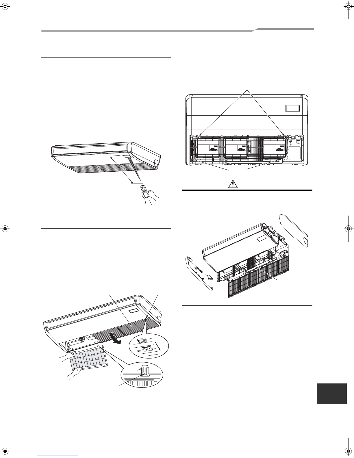
1 Removal of suction grille
Slide the suction grille fixing knobs (2 positions)
toward the arrow direction, and then open the
suction grille.
Under the condition of suction grille opened, push
the hook section of hinges (2 positions) at the rear
side, and then pull out the suction grille.
Hinge
Suction grille
fixing knob
Suction grille
Pull out suction grille
while pushing hook.
Wire guard
S
l
i
d
e
EN
–6–
6-EN
Page 8
Under Ceiling Type
3 Removal of side panel
After removing the side panel fixing screws (1
each at right and left), slide the side panel forward
and then remove it.
Protector
Side panel
Level louver
Slide forward.
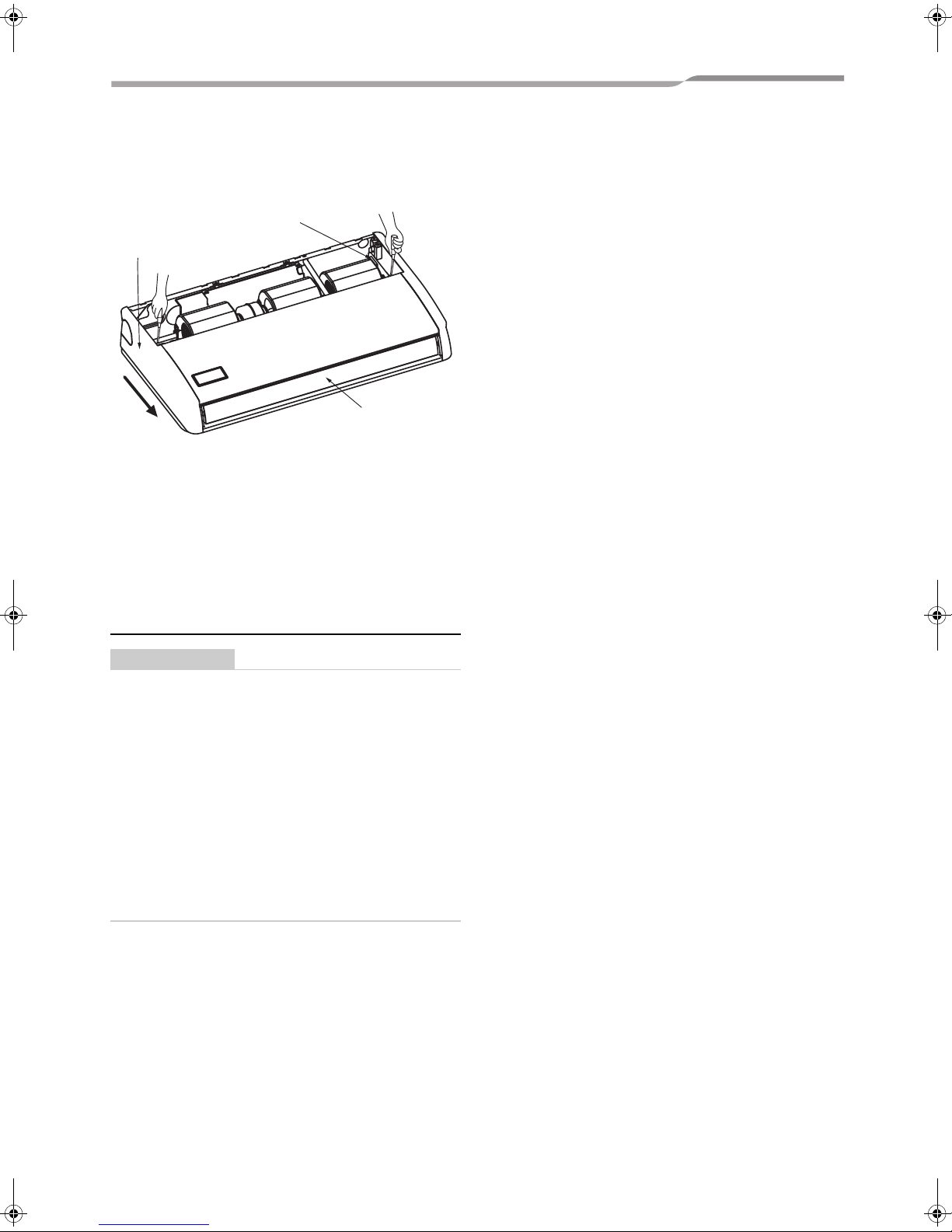
4 Removal of protective vinyl
Peel out the protective vinyl on the level louver.
Installation Manual
5 Removal of protector
Remove the protector (1 pcs.) of the fan.
(RAV-SP240CT only)
External view
REQUIREMENT
Strictly comply with the following rules to prevent
damage of the indoor units and human injury.
• Do not put a heavy article on the indoor unit. (Even
units are packaged)
• Carry in the indoor unit as it is packaged if possible.
If carrying in the indoor unit unpacked by necessity,
be sure to use buffering cloth, etc. to not damage
the unit.
• Do not apply force to the other parts (refrigerant
pipe, drain pan, foamed parts, or resin parts, etc.).
• Carry the package by two or more persons, and do
not bundle it with plastic band at positions other
than specified.
7-EN
–7–
Page 9
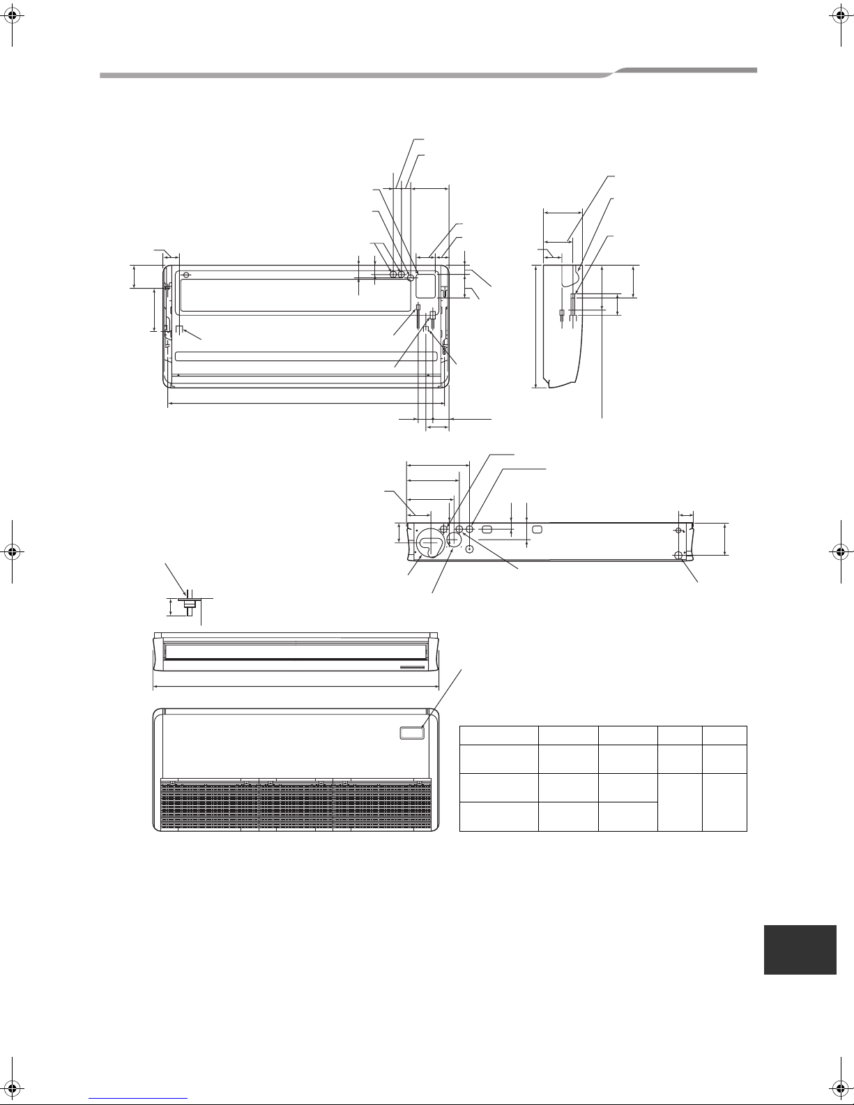
Under Ceiling Type
Upper pipe draw-out port (knockout)
Hole for remote control wires (knockout)
3.3” (84)
6.7” (170)
(Hole for power supply cable. knockout)
12.6” (320)
Left drain size
Conduit hole
2.8”
(70)
Refrigerant pipe
(Liquid side ØC)
Refrigerant pipe (Gas side ØD)
B (Hanging position)
3.0” (75)
5.3” (135)
2.1”
(53)
12.2” (311)
10.3” (262)
1.5” (39)
2.0” (52)
8.5” (216)
5.7” (146)
13.7” (347)
3.5”
(90)
4.3” (110)
3.0” (76)
4.1” (105)
5.1” (130)
Drain pipe
connecting
port
3.8” (97)
8.3” (210)
2.0” (50)
26.8” (680)
7.9” (200) (Liquid pipe)
Hole for remote control wires
Conduit hole
(knockout)
3.6” (92)
1.3” (32)
Installation Manual
Unit: in (mm)
6.6” (167)
Pipe draw-out port
(knockout)
Drain port VP20
(Inner dia. Ø1.0” (26), hose
attached)
4.5” (114)
5.6” (141)
8.5” (216) (Gas pipe)
3.3” (84)
Hanging bolt
Within
2.0” (50)
Ceiling surface
Unit
Pipe hole on wall
(Ø3.9” (100) hole)
A
Outside air take-in port (Duct sold separately)
Knockout hole Ø3.6” (92))
5.7” (145)
Hole for power supply cable
Left drain pipe
draw-out port
(knockout)
Wireless sensor
mounting section
Unit: in (mm)
Model name A B C D
180CT
240CT
300CT, 360CT
to 420CT
35.8”
(910)
46.5”
(1180)
62.8”
(1595)
33.7”
(855)
44.3”
(1125)
60.6”
(1540)
Ø1/4”
(6.4)
Ø3/8”
(9.5)
Ø1/2”
(12.7)
Ø5/8”
(15.9)
Considering pipe/wire connecting work inside the ceiling after the indoor unit has been hanged, select an
installation place and determine piping direction.
• If the ceiling has already been set before hanging the main unit, prepare refrigerant pipe, drain pipe, indoor
connecting wire, remote control cord, etc. up to the place where pipe and wire can be connected.
• Check the size of the indoor unit, and match the indoor unit size using the attached installation pattern.
6.7” (171)
EN
–8–
8-EN
Page 10

Under Ceiling Type
Installation Manual
Using attached installation pattern
Ceiling surface
Wall face
Installation pattern
Using the pattern, positioning of the hanging bolt and
pipe hole can be performed.
* As an error to some degree may generate on the
pattern size due to temperature and humidity, be
sure to confirm the size.
Installation of hanging bolts
Use 3/8” (M10) hanging bolts (4 pcs, to be local
procure).
Matching to the existing structure, set pitch according
to size in the unit external view as shown below.
New concrete slab
Install the bolts with insert brackets or anchor bolts.
Rubber
(Blade type
bracket)
Use existing angles or install new support angles.
(Slide type
bracket)
Steel flame structure
Hanging bolt
Anchor bolt
(Pipe hanging
anchor bolt)
Pipe knockout hole
• Piping from rear side
* Cut off the groove section with a plastic cutter, etc.
Rear cover
100
Opened when
Grooves
Opened when only drain pipe is
taken out from the rear side
• Piping from right side
* Cut off the groove section with a metal saw or
plastic cutter, etc.
• Piping from left side
Taking pipe from left side is applied only to the
drain pipe.
The refrigerant pipe cannot be taken out from the
left side.
* Cut off the groove section with a metal saw or
plastic cutter, etc.
refrigerant pipe is
taken out from the
rear side
Groove
Side panel (Right side)
Hanging bolt Support angle
Existing concrete slab
Use a hole-in anchors, hole-in plugs, or a hole-in bolts.
Draw-out direction of pipe/
wire
• Decide installation place of the unit and draw-out
direction of pipe and wire.
9-EN
Groove
• Piping from upper side
Taking pipe from upper side is applied only to
the refrigerant pipe.
When taking out the drain pipe from the upper
side, use a drain up kit sold separately.
Open the upper pipe draw-out port (Knockout hole)
shown in the external view.
(Knockout hole of thin plate)
After piping, cut off the attached thermal insulator of
the top plate to pipe shape, and then seal the
knockout hole.
–9–
Side panel (Left side)
Page 11

Under Ceiling Type
Installation Manual
Installation of indoor unit
• Preparation before holding down main unit
* Confirm the presence of the ceiling material
beforehand because the fixing method of hanging
metal when the ceiling material is set differs from
that when the ceiling material is not set.
▼ There is ceiling material
Hanging bolt
(Procured locally)
Indoor
unit
Hanging metal
Nut
(Procured locally)
Indoor
unit
Hanging metal
* Tighten the hanging metal with upper/lower nuts
as shown in the figure.
▼ There is no ceiling material
Indoor
unit
• Holding down of main unit
(1) Attach washer and nuts to the hanging bolt.
Ceiling surface
Ceiling surface
Washer (Accessory)
Double nut
(Procured locally)
Hanging bolt
(Procured locally)
Ceiling surface
Washer (Accessory)
Double nut
(Procured locally)
Hanging bolt
(Procured locally)
Washer
(Procured locally)
Washer (Accessory)
Double nut
(Procured locally)
2.0” (50 mm)
(2) Hang the unit to the hanging bolt as shown the
figure below.
(3) As shown in the figure below, fix the ceiling material
securely with the double nuts.
REQUIREMENT
• The ceiling surface may not be horizontal. Be
sure to confirm that width and depth directions
are level.
Installation of remote control
(Sold separately)
For installation of the wired remote control, follow the
Installation Manual attached with the remote control.
• Pull out the remote control cord together with the
refrigerant pipe or drain pipe.
Be sure to pass the remote control cord through
upper side of the refrigerant pipe and drain pipe.
• Do not leave the remote control at a place exposed
to the direct sunlight and near a stove.
• Operate the remote control, confirm that the indoor
unit receives a signal surely, and then install it.
(Wireless type)
• Keep 3’3” (1 m) or more from the devices such as
television, stereo, etc.
(Disturbance of image or noise may generate.)
(Wireless type)
Washer
(Accessory)
Hanging bolt
Double nut
(Procured locally)
0.8” - 1.2”
(20 - 30 mm)
–10–
EN
10-EN
Page 12

Under Ceiling Type
Installation Manual
4 REFRIGERANT PIPING AND EVACUATING
Refrigerant Piping
• The connecting sections of the refrigerant pipes are
provided at the positions in the figure below.
Upper side
Right
Rear side
1. Use copper pipe with 0.03” (0.8 mm) or more
thickness.
(In case pipe size is Ø5/8” (15.9 mm), with 0.04” (1.0
mm) or more.)
2. Flare nut and flare works are also different from
those of the conventional refrigerant.
Take out the flare nut attached to the main unit of the
air conditioner, and use it.
REQUIREMENT
When the refrigerant pipe is long, provide support
brackets at intervals of 8’2” - 9’10” (2.5 - 3 m) to clamp
the refrigerant pipe. Otherwise, abnormal sound may
be generated.
* When using the drain
pump kit sold separately,
the pipe can be drawn out
only from the upper side.
Permissible Piping Length
and Height Difference
They vary according to the outdoor unit.
For details, refer to the Installation Manual attached to
the outdoor unit.
Flaring
• Cut the pipe with a pipe cutter.
Remove burrs completely.
Remaining burrs may cause gas leakage.
• Insert a flare nut into the pipe, and flare the pipe.
As the flaring sizes of R410A differ from those of
refrigerant R22, the flare tools newly manufactured
for R410A are recommended.
However, the conventional
tools can be used by adjusting
projection margin of the
copper pipe.
▼ Projection margin in
flaring: B (Unit: in (mm))
Rigid (Clutch type)
Outer dia. of
copper pipe
1/4” - 5/8”
(6.4 - 15.9)
R410A tool used
0 - 0.02”
(0 - 0.5)
Conventional
tool used
0.04” - 0.06”
(1.0 - 1.5)
B
CAUTION
IMPORTANT 4 POINTS FOR PIPING WORK
1. Remove dust and moisture from the inside of the
connecting pipes.
2. Tight connection (between pipes and unit)
3. Evacuate the air in the connecting pipes using
VACUUM PUMP.
4. Check the gas leakage. (Connected points)
Pipe size
Model
name
Pipe size
RAV-
Gas side
Liquid side
SP180
type
1/2"
(12.7 mm)
1/4"
(6.4 mm)
SP240, SP300,
SP360, SP420
type
5/8"
(15.9 mm)
3/8"
(9.5 mm)
Outer dia. of copper pipe
1/4” (6.4) or 3/8” (9.5) 0.06” - 0.08” (1.5 - 2.0)
1/2” (12.7) or 5/8” (15.9) 0.08” - 0.1” (2.0 - 2.5)
Imperial
(Wing nut type)
▼ Flaring dia. meter size: A (Unit: in (mm))
Outer dia. of copper pipe A
1/4” (6.4) 0.36” (9.1)
3/8” (9.5) 0.52” (13.2)
1/2” (12.7) 0.65” (16.6)
5/8” (15.9) 0.78” (19.7)
+0
-0,02" (–0.4)
* In case of flaring for R410A with the
conventional flare tool, pull it out approx.
0.02” (0.5 mm) more than that for R22 to
adjust to the specified flare size.
The copper pipe gauge is useful for
adjusting projection margin size.
A
11-EN
–11–
Page 13

Under Ceiling Type
Installation Manual
Tightening connection
CAUTION
• Do not apply excessive torque. Otherwise, the nut
may crack depending on the conditions.
(Unit: ft•lbs (N•m))
Outer dia. of copper
▼
Tightening torque of flare pipe connections
pipe
1/4” (6.4 mm) 10 -13 (14 - 18)
3/8” (9.5 mm) 24 - 31 (33 - 42)
1/2” (12.7 mm) 37 - 46 (50 - 62)
5/8” (15.9 mm) 46 - 57 (63 - 77)
Pressure of R410A is higher than that of R22.
(Approx. 1.6 times)
Therefore, using a torque
wrench, tighten the flare pipe
connecting sections which
connect the indoor and
outdoor units of the specified
tightening torque.
Incorrect connections may
cause not only a gas leak, but
also a trouble of the
refrigeration cycle.
Align the centres of the connecting pipes and tighten
the flare nut as far as possible with your fingers. Then
tighten the nut with a spanner and torque wrench as
shown in the figure.
Tightening torque
Flare at
outdoor
unit side
Flare at
indoor
unit side
Evacuation
Using a vacuum pump, perform vacuuming from the
charge port of valve of the outdoor unit.
For details, follow to the Installation Manual attached to
the outdoor unit.
• Never use the refrigerant sealed in the outdoor unit
for air purge.
REQUIREMENT
For the tools such as charge hose, etc., use those
manufactured exclusively for R410A.
Refrigerant amount to be added
For addition of the refrigerant, add refrigerant “R410A”
referring to the attached Installation Manual of outdoor
unit.
Be sure to use a scale to charge the refrigerant of
specified amount.
REQUIREMENT
• Charging an excessive or too little amount of
refrigerant causes a trouble of the compressor.
Be sure to charge the refrigerant of specified
amount.
• A personnel who charged the refrigerant should
write down the pipe length and the added
refrigerant amount in the nameplate attached to the
service panel of the outdoor unit. It is necessary to
troubleshooter the compressor and refrigeration
cycle malfunction.
Half union Flare nut
Externally
threaded side
Use a wrench to secure. Use a torque wrench to tighten.
REQUIREMENT
Tightening with an excessive torque may crack the nut
depending on installation conditions.
Tighten the nut within the specified tightening torque.
Piping with outdoor unit
• Shape of valve differs according to the outdoor unit.
For details of installation, refer to the Installation
Manual of the outdoor unit.
Internally
threaded side
Open the valve fully
Open the valve of the outdoor unit fully.
For details, refer to the Installation Manual attached to
the outdoor unit.
Gas leak check
Check with a leak detector or soap water whether gas
leaks or not, from the pipe connecting section or cap of
the valve.
REQUIREMENT
Use a leak detector manufactured exclusively for HFC
refrigerant (R410A, R134a, etc.).
–12–
EN
12-EN
Page 14

Under Ceiling Type
Thermal insulation process
Apply thermal insulation for the pipes separately at
liquid side and gas side.
For the thermal insulation to the pipes at gas side, be
sure to use the material with heat-resisting
temperature 248 °F (120 °C) or higher.
Using the attached thermal insulation material, apply
the thermal insulation to the pipe connecting section of
the indoor unit securely without gap.
REQUIREMENT
• Apply the thermal insulation to the pipe connecting
section of the indoor unit securely up to the root
without exposure of the pipe. (The pipe exposed to
the outside causes water leak.)
• Wrap heat insulator with its slits facing up (ceiling
side).
Wrap the pipe with the attached heat insulator
without any gap between the indoor unit.
Indoor unit
The seam must be faced upward
(ceiling side).
Installation Manual
Heat insulation
pipe
(Accessory)
Union
Flare nut
Heat insulator
of the pipe
13-EN
–13–
Page 15

Under Ceiling Type
5 DRAIN PIPING WORK
Installation Manual
CAUTION
• Following the Installation Manual, perform the
drain piping work so that water is properly
drained, and apply a heat insulation so as not to
cause a dew dropping.
Inappropriate piping work may result in water
leakage in the room and wet of furniture.
Piping/Heat insulating
material
Require the following materials for piping and heat
insulating at site.
Piping
Heat insulator
REQUIREMENT
• Be sure to perform heat insulation of the drain pipes
of the indoor unit.
• Never forget to perform heat insulation of the connecting
part with the indoor unit.
An incomplete heat insulation causes dew dropping.
• Set the drain pipe with downward slope (1/100 or
more), and do not make swelling or trap on the
piping. It may cause an abnormal sound.
• For length of the traversing drain pipe, restrict 65’7”
(20 m) or less.
In case of a long pipe, provide support brackets with
interval of 4’11” - 6’7” (1.5 - 2 m) in order to prevent
waving.
Hard vinyl chloride pipe VP20
(Outer dia.: Ø1.0” (26 mm))
Foam polyethylene:
Thickness 0.4” (10 mm) or more
4’11” - 6’7” (1.5 - 2 m)
1/100 or more
downward
Support
bracket
• Set the collective piping as shown in the below
figure.
As long as possible
(3.9” (100 mm))
VP20
VP30 or more
VP20 VP20
Downward slope
1/100 or more
<Collective piping>
Extended
ventilating
pipe
• Be sure not to apply force to the connecting part of
the drain pipe.
• The hard vinyl-chloride pipe cannot be directly
connected to the drain pipe connecting port of the
indoor unit.
For connection with the drain pipe connecting port,
be sure to use/fix the attached flexible hose with the
hose band, otherwise a damage or water leak is
caused on the drain pipe connecting port.
Drain pipe connecting
port (Hard socket)
Drain pan
Adhesive agent
prohibited
Attached flexible hose
Attached hose bandAttached hose band
Soft socketSoft socket
VP20 vinyl chloride pipe
(procured locally)
Adhesive inhibited:
Use the attached flexible hose and hose band for
connecting the drain hose to the clear drain socket.
If applying the adhesive, socket will be damaged and
cause water leakage.
Thermal insulator
Arched shape
Trap
NO
GOOD
Drain up
When not securing down slope on the drain pipe, use
a Drain pump kit sold separately.
Also refer to the “Drain pump kit installation manual”.
The drain pipe can be raised 23.6” (600 mm) from the
top face of the main unit.
* When using Drain pump kit, both drain pipe and
refrigerant pipe can be taken only from upper side.
* VP25 PVC pipe is needed when a drain pump is
used.
–14–
EN
14-EN
Page 16

Under Ceiling Type
Installation Manual
Connection of drain hose
• Insert the attached drain hose into the drain pipe
connecting port on the drain pan up to the end.
• Fit the attached hose band to the end of the pipe
connecting port, and then tighten it securely.
REQUIREMENT
• Be sure to fix the drain hose with the attached hose
band, and set the tightening position upward.
• As the draining is the natural water draining,
arrange the pipe outside of the unit on the down
slope.
• If piping is performed as shown in the figure, drain
cannot be discharged.
NO GOOD
Drain pipe
Fit the attached hose band to the end of the hose, lay
down the knob, and then tighten hose band.
Refrigerant pipe
Drain pipe
Connection of drain pipe
• Connect the hard vinyl chloride pipe (procured
locally) to the mounted drain hose which was
attached.
• Piping from left side
• In case of taking pipe from the left side, exchange
the plug from left to right. Push in the plug of which
end is not sharp up to the end.
Drain pan
Plug
Drain pan
Attached drain hose
Confirm that soft hose is pushed
in up to the end of the drain pan.
Thermal insulating process
• Using the attached drain hose thermal insulator, lap
the connecting section and the drain hose without
clearance, and then tighten with two handing band
so that thermal insulator does not open.
• Covering the attached drain hose thermal insulator,
lap the thermal insulator (procured locally) to the
drain pipe without clearance.
Lap covering connecting section
between drain pan and drain hose.
Drain hose
Drain
pan
Hose band
* Tighten the banding band so that
attached thermal insulator is not
pushed excessively.
Banding band
Attached thermal insulator
Hose band
Thermal insulator
(procured locally)
Lap the attached
thermal insulation
so that the one
end is put on the
other end at the
upper side.
15-EN
–15–
Page 17

Under Ceiling Type
6 ELECTRICAL CONNECTION
Installation Manual
WARNING
1. Using the specified wires, ensure to connect the
wires, and fix wires securely so that the external
tension to the wires do not affect the connecting
part of the terminals.
Incomplete connection or fixation may cause a fire,
etc.
2. Be sure to connect ground wire. (grounding work)
Incomplete grounding cause an electric shock.
Do not connect ground wires to gas pipes, water
pipes, lightning rods or ground wires for telephone
wires.
3. Appliance shall be installed in accordance with
national wiring regulations.
Capacity shortage of circuit breaker or incomplete
installation may cause an electric shock or a fire.
CAUTION
• Consult local building codes, NEC (National Electrical
Code) or CEC (Canadian Electrical Code) for special
requirements.
• This indoor unit has no power cord.
• If incorrect/incomplete wiring is carried out, it will
cause an electrical fire or smoke.
• Be sure to install circuit breaker is not tripped by shock
waves.
If circuit breaker is not installed, an electric shock may
be caused.
• Be sure to use the cord clamps attached to the
product.
• Do not damage or scratch the conductive core and
inner insulator of power and system interconnection
wires when peeling them.
• Use the power cord and system interconnection wire
of specified thickness, type, and protective devices
required.
REQUIREMENT
• For power supply wiring, strictly conform to the
Local Regulation in each country.
• For wiring of power supply of the outdoor units,
follow the Installation Manual of each outdoor unit.
• Never connect 208/230 V power to the terminal
blocks (A, B etc.) for control wiring.
(Otherwise, the system will fail.)
• Perform the electric wiring so that it does not come
to contact with the high-temperature part of the
pipe.
The coating may melt resulting in an accident.
• Run the refrigerant piping line and control wiring line
in the same line.
• Do not turn on the circuit breaker of the indoor unit
until vacuuming of the refrigerant pipes completes.
Remote control wiring
• For single system, use 2 x AWG20 non polarity wire
is used for the remote control wiring.
Wiring
1. Connect the connecting wire to the terminal as
identified with their respective numbers on the
terminal block of indoor and outdoor unit.
(4
x AWG12)
2. Insulate the unsheathed redundant cords
(conductors) with electrical insulation tape.
Process them so that they do not touch any electrical
or metal parts.
3. For inter-unit wiring, do not use a wire jointed to
another on the way.
Wire Quantity x size
Indoor unit - Outdoor unit *1 3 x AWG12 (polar)
Ground 1 x AWG12 or thicker
Remote control 2 x AWG20 (non-polar)
*1 :Length of the system interconnection wires.
RAV- SP180AT2 SP240AT2
Wire
length
164’1” (50
m) or less
229’8” (70
m) or less
–16–
SP300AT2 -
SP420AT2
246’1” (75 m) or
less
EN
16-EN
Page 18

Under Ceiling Type
CAUTION
Use the same size wire for the field power supply wire
and system interconnection wires when the outdoor unit
is RAV-SP180AT2.
NOTE
• Use copper supply wires.
• Use UL wires rated 600 V for the system
interconnection wires.
• Use UL wires rated 300 V for the remote control
wires.
Installation Manual
17-EN
–17–
Page 19

Under Ceiling Type
Installation Manual
Wire connection
REQUIREMENT
• Be sure to connect the wires matching the terminal numbers. Incorrect connection causes a trouble.
• The low-voltage circuit is provided for the remote control. (Do not connect the high-voltage circuit)
• Loosen the cover mounting screws (2 positions) of the electric parts box, and then remove the cover.
• Attach the conduit pipe to the conduit hole with a lock nut.
• Slit the film of bushing attached to the hole for remote control wire, and then pass through wires.
• Connect the system interconnection wires and the remote control wire to the terminal block of the electric parts
box. Secure the ground wire with the ground screw.
• Tighten screws of the terminal block securely, and fix the wires with code clamp attached to the electric parts
box. (Do not apply tension to the connecting section of the terminal block.)
• Mount the cover of the electric parts box so that it does not pinch the wires.
Electric parts box
Terminal block for
wired remote
control
Wire partition plate
Pass the remote control wire through the
hole for remote control wire and behind
this wire partition plate.
Two screws
A
B
P.C. board
Terminal block for system
interconnection
L
1
L
2
S
Terminal block
Ground screw
System interconnection
wires and ground wire
Cord clamp
Remote control wires
Hole for Remote control wires
Conduit hole
–18–
EN
18-EN
Page 20

Under Ceiling Type
Installation Manual
CAUTION
Fix the system interconnection wires and the remote control wires separately with the cord clamps as shown below.
Connected at backside
Cord clamp
Conduit pipe
Cord clamp
Hole for
remote control wires
Connected at upside
Conduit hole for
system
interconnection wires
Conduit hole (knockout)
for system
interconnection wires
Hole for
remote control wires
(knockout)
Attach the supplied
bushing to cover the
hole edge.
19-EN
Cord clamp
Attach the supplied
bushing to seal the
back side conduit hole.
–19–
Cord Clamp
Cord Clamp
Page 21

Under Ceiling Type
Installation Manual
System interconnection
Wires and Ground Wire
1. Strip wire ends.
System interconnection wire : 0.4” (10 mm).
Ground wire : 0.8” (20 mm)
2. Match wire colours with terminal numbers on indoor
and outdoor units’ terminal blocks and firmly screw
wires to the corresponding terminals.
3. Secure the ground wire with the ground screw.
4. Fix the wire with cord clamp.
Unit: in (mm)
0.8” (20)
Ground wire
0.4” (10)
Connecting wire
L
1
S
L
2
CAUTION
Remote Control Wiring
• Strip off approx. 0.4” (9 mm) the wire to be
connected.
• Non polarity, 2 x AWG20 wire is used for wiring of the
remote control.
Terminal block for
remote control wiring
of indoor unit
A
B
Remote control wire
(Procured locally)
Terminal block
Remote
A
control
B
unit
Wiring Diagram
▼ Single system
Indoor unit
Low voltage
A B
Remote
control
Outdoor
unit
208/230-1-60
L
1
L
2
S
High voltage
L
1
L
2
S
• Firmly tighten the screws of the terminal block.
Keep the wire length as shown in figure below when it
is connected to the terminal block.
0.08” (2 mm) or less
System
interconnection wire
EN
–20–
20-EN
Page 22

Under Ceiling Type
7 APPLICABLE CONTROLS
Installation Manual
REQUIREMENT
• When you use this air conditioner for the first time,
it takes approx. 5 minutes until the remote control
becomes available after power-on. This is normal.
<When power is turned on for the first time after
installation>
It takes approx. 5 minutes until the remote control
becomes available.
Approx. 5 minutes
Power
on
<When power is turned on for the second (or
later) time>
It takes approx. 1 minute until the remote control
becomes available.
Power
on
• Normal settings were made as factory default.
Change the indoor unit settings as required.
• Use the wired remote control to change the
settings.
* The settings cannot be changed using the
“SETTING”
flashes
“SETTING”
flashes
wireless remote control, sub remote control,
or remote-controlless system (for central
remote control only). Therefore, install the
wired remote control to change the settings.
“SETTING”
goes out
Approx. 1 minutes
“SETTING”
goes out
Remote
control is
available
Remote
control is
available
Changing applicable control
setting
Basic procedure for changing settings
Change the settings while the air conditioner is not
working.
(Be sure to stop the air conditioner before making
settings.)
4
6
1
Procedure 1
When pushing , , and buttons simultaneously
for 4 seconds or more, after a while, the display part
flashes as shown in the figure.
Check that the displayed CODE No. is [10].
• If the CODE No. indicates other than [10], push
button to erase the display, and then retry the
operation from the first step.
(For some time after button has been pushed, the
operation of the remote control cannot be accepted.)
(In a group control, the firstly displayed indoor UNIT
No. becomes the master unit.)
3
5
2
21-EN
(* Display content varies with
the indoor unit model.)
Procedure 2
Every pushing button, the indoor UNIT No. in
the group control is displayed successively.
Select an indoor unit of which setup to be changed.
In this time, the position of the indoor unit of which
setup to be changed can be confirmed because the fan
and the louver of the selected indoor unit work.
Procedure 3
Using temp. setup / buttons, specify CODE
No. [ ].
Procedure 4
Using timer time / buttons, select SET DATA [
].
–21–
Page 23

Under Ceiling Type
Installation Manual
Procedure 5
Push button. In this time, if the display changes
from flashing to lighting, the setup completes.
• To change the setup of an indoor unit other than the
selected one, start operation from Procedure
• To change the setup of another setup in the selected
indoor unit, start operation from Procedure
Pushing button clears the set up contents which
have been already set. In this case, retry from
Procedure
2.
2.
3.
Procedure 6
When settings have been completed, push button
to determine the settings.
When button is pushed, “SETTING” flashes and
then the display content disappears and the air
conditioner enters the normal stop mode.
(While “SETTING” is flashing, no operation of the
remote control is accepted.)
Installation to high ceiling
When the height of the ceiling to be installed exceeds
3.5 m (11’6”), adjustment of fan speed is necessary.
Set up the high ceiling.
• Set according to the basic operation procedure
(
1 → 2 → 3 → 4 → 5 → 6).
• Item code in Procedure specifies [5d].
• Select [SET DATA] in Procedure from “List of
installable ceiling height” in this Manual.
• For the item code in Procedure
• For the SET DATA in Procedure
data of static pressure to be set up from the table on
the right.
(Exchange by wired remote control)
3, specify [5d].
4, select the setup
Using wireless remote control
Change the high ceiling setting with the DIP switch on
the P.C. board of the signal receiving part.
Refer to the installation manual of the wireless remote
controller kit for the details.
High ceiling setting can be changed by arranging the
jumper block on the indoor unit micro computer P.C.
board as shown in the table below as well.
* However, once the setting is changed, it is
necessary to reset the setting back to 0000 that
placing the jumper block back to the factory default
position and rewriting the setting data back to 0000
with wired remote control (sold separately). (The
setting can be changed to 0001, 0003 and 0006
without resetting.)
• Select by exchange of jumper block on indoor
microcomputer P.C. board.
jumper block
position
SET DATA Note
Short Open
0000
0001 High static pressure 1
• Jumper block position
(CN112, CN111, CN110 from the left)
Standard filter
(Factory default)
SET DATA
0000
0001 High static pressure 1
Standard
(Factory default)
11’6” (3.5 m) or less
more than 11’6” (3.5 m)
up to 13’1” (4.0 m)
–22–
EN
22-EN
Page 24

Under Ceiling Type
Installation Manual
Filter sign setting
According to the installation condition, the lighting time
of the filter sign (Notification of filter cleaning) can be
changed.
Follow to the basic operation procedure
(
1 → 2 → 3 → 4 → 5 → 6).
• For the CODE No. in Procedure
• For the [SET DATA] in Procedure
3, specify [01].
4, select the setup
data of filter sign lighting time from the following
table.
Setup data Filter sign lighting time
0000 None
0001 150H
0002 2500H (Factory default)
0003 5000H
0004 10000H
To secure better effect of
heating
When it is difficult to obtain satisfactory heating due to
installation place of the indoor unit or structure of the
room, the detection temperature of heating can be
raised. Also use a circulator, etc. to circulate heat air
near the ceiling.
Follow to the basic operation procedure
(
1 → 2 → 3 → 4 → 5 → 6).
• For the CODE No. in Procedure
• For the SET DATA in Procedure
data of shift value of detection temperature to be set
up from the table below.
Setup data Detection temp shift value
0000 No shift
0001 +1.8 °F (+1 °C)
0002
0003 +5.4 °F (+3 °C)
0004 +7.2 °F (+4 °C)
0005 +9.0 °F (+5 °C)
0006 +10.8 °F (+6 °C)
+3.6 °F (+2 °C)
(Factory default)
3, specify [06].
4, select the setup
Group control
Group control for system of multiple units
One remote control can control maximum 8 indoor
units as a group.
▼ Group control in single system
Outdoor
unit
Indoor
unit
Remote
control
Outdoor
unit
Indoor
unit
Finish of address setup by
power-ON
Outdoor
unit
Indoor
unit
• For wiring procedure and wiring method of the
individual line (Identical refrigerant line) system,
follow to “Electric work”.
• Wiring between lines is performed in the following
procedure.
Connect the terminal block (A/B) of the indoor unit
connected with a remote control to the terminal
blocks (A/B) of the indoor units of other indoor units
by wiring the inter-unit wire of the remote control.
• When the power supply has been turned on, the
automatic address setup starts and “ ” display
which indicates that address is being set up flashes
on the display part. During setup of automatic
address, the remote control operation is not
accepted.
Required time up to the finish of automatic
addressing is approx. 5 minutes.
NOTE
In some cases, it is necessary to change the address
manually after setup of the automatic address
according to the system configuration of the group
control.
Procedure example 1
Manual address setup procedure
While the operation stops, change the setup.
(Be sure to stop the operation of the unit.)
Outdoor
unit
Indoor
unit
Outdoor
unit
Indoor
unit
(Max. 8 units)
23-EN
–23–
Page 25

Under Ceiling Type
3
-2,
4
-2,
5
-2
7
3
4
5
Installation Manual
Indoor UNIT No. before setup change is displayed.
-1,
-1,
-1,
7
2,61
Procedure 1
Push simultaneously + + buttons for 4
seconds or more. After a while, the display part flashes
as shown below. Check the displayed CODE No. is
[10].
• When the CODE No. is other than [10], push
button to erase the display and repeat procedure
from the first step.
(After pushing
control is not accepted for approx. 1 minute.)
(For a group control, No. of the firstly displayed
indoor unit becomes the header unit.)
Procedure 2
Every pushing button, the indoor UNIT No. in
the group control is displayed in order. Select the
indoor unit of which setup is changed.
In this time, the position of the indoor unit of which
setup is changed can be confirmed because fan and
louver of the selected indoor unit operate.
Procedure 3
1. Using temp. setup / buttons, specify CODE
No. [12].
(CODE No. [12]: Line address)
2. Using timer time / buttons, change the line
address from [3] to [2].
3. Push button.
In this time, the setup finishes when the display
changes from flashing to lighting.
button, operation of the remote
(* Display changes according to
the model No. of indoor unit.)
3
4
5
-3,
-3,
-3,
Procedure 4
1. Using temp. setup / buttons, specify CODE
No. [13].
(CODE No. [13]: Indoor address)
2. Using timer time / buttons, change the indoor
address from [3] to [2].
3. Push button.
In this time, the setup finishes when the display
changes from flashing to lighting.
Indoor UNIT No. before setup change is displayed.
Procedure 5
1. Using temp. setup / buttons, specify CODE
No. [14].
(CODE No. [14]: Group address)
2. Using timer time / buttons, change the setup
data from [0001] to [0002].
(Setup data [Header unit: 0001] [Follower unit:
0002])
3. Push button.
In this time, the setup finishes when the display
changes from flashing to lighting.
Indoor UNIT No. before setup change is displayed.
–24–
EN
24-EN
Page 26

Under Ceiling Type
Procedure 6
If there is other indoor unit to be changed, repeat
procedure
When the above setup has finished, push to
select the indoor UNIT No. before change of setup,
specify CODE No. [12], [13], [14] in order with temp.
setup / buttons, and then check the changed
contents.
Address change check Before change:
[3-3-1] → After change: [2-2-2]
2 to 5 to change the setup.
1,3
Installation Manual
1
2
Pushing button clears the contents of which setup
was changed.
(In this case, procedure from
Indoor UNIT No. before setup change is displayed.
2 is repeated.)
Procedure 7
After check of the changed contents, push button.
(Setup is determined.) When pushing
display disappears and the status becomes the usual
stop status. (When pushing
from the remote control is not accepted for approx.
1 minute.)
* If the operation from the remote control is not
accepted even 1 minute or more passed after
pushing
setup is incorrect.
In this case, the automatic address must be again
set up.
Therefore repeat procedure of the setup change
from the Procedure
button, it is considered that the address
button the operation
1.
button, the
To recognize the position of the
corresponding indoor unit though the
indoor UNIT No. is known
Check the position during operation stop.
(Be sure to stop operation of the set.)
Procedure 1
Push simultaneously + buttons for 4 seconds
or more.
After a while, the display part flashes and the display
appears as shown below.
In this time, the position can be checked because fan
and louver of the indoor unit operate.
• For the group control, the indoor UNIT No. is
displayed as [ ] and fans and louvers of all the
indoor units in the group control operate.
Check the displayed CODE No. is [01].
• When the CODE No. is other than [01], push
button to erase the display and repeat procedure
from the first step.
(After pushing
control is not accepted for approx. 1 minute.)
button, operation of the remote
(* Display changes according to
the model No. of indoor unit.)
Procedure 2
In the group control, every pushing button, the
indoor UNIT No. in the group control is displayed in
order.
In this time, the position of the indoor unit can be
confirmed because only fan of the selected indoor unit
operate.
(For a group control, No. of the firstly displayed indoor
unit becomes the header unit.)
Procedure 3
After confirmation, push button to return the mode
to the usual mode.
When pushing
the status becomes the usual stop status.
(When pushing
remote control is not accepted for approx. 1 minute.)
button, the display disappears and
button the operation from the
25-EN
–25–
Page 27

Under Ceiling Type
Installation Manual
Remote control switch
monitoring function
This function is available to call the service monitor
mode from the remote control during a test run to
acquire temperatures of sensors of the remote control,
indoor unit, and outdoor unit.
1. Push and
4 seconds to call the service monitor mode.
The service monitor indicator lights up and the
header indoor unit number is displayed first. CODE
No. is also displayed.
2. Pushing TEMP. buttons, select the
number of sensor, etc. (CODE No.) to be monitored.
(See the following table.)
3. Pushing
indoor unit to be monitored. The sensor
temperatures of indoor units and their outdoor unit in
the control group are displayed.
4. Push
button to return to the normal display.
buttons simultaneously for at least
(left side of the button), select an
Outdoor unit data
CODE No. Data name
60
61 Outside air temperature (TO)
62 Compressor discharge air temperature (TD)
63 Compressor intake air temperature (TS)
64 —
65 Heatsink temperature (THS)
6A Operating current (x1/10)
F1
Outdoor unit heat exchanger temperature
(TE)
Compressor cumulative operating hours
(x100h)
2
4
13
Indoor unit data
CODE No. Data name
01 Room temperature (remote control)
02 Indoor unit intake air temperature (TA)
03
04
F3
F8 Indoor unit discharge air temperature
Indoor unit heat exchanger temperature
(TCJ)
Indoor unit heat exchanger temperature
(TC)
Indoor unit fan cumulative operating hours
(x1 h)
–26–
EN
26-EN
Page 28
Under Ceiling Type
8 TEST RUN
Installation Manual
Before test run
• Before turning on the circuit breaker, carry out the
following procedure.
1) Using 500V-megger, check 1MΩ or more exists
between the terminal block L
ground.
If 1MΩ or less is detected, do not run the unit. Do
not apply to the remote control circuit.
2) Check the valve of the outdoor unit being opened
fully.
• To protect the compressor at activation time, leave
power-ON for 12 hours or more be for operating.
1 to L2 and the
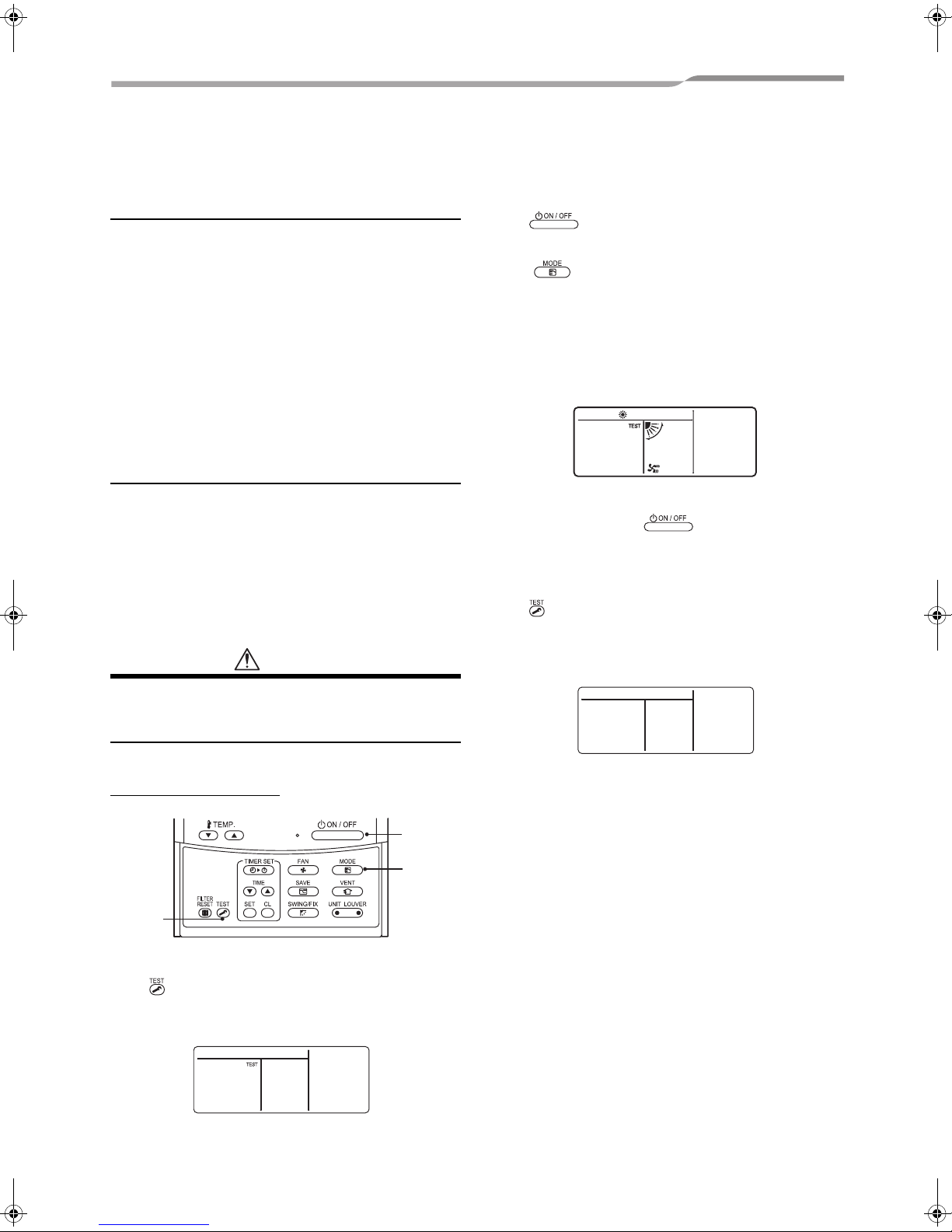
Execute a test run
Using the remote control, operate the unit as usual.
For the procedure of the operation, refer to the
attached Owner’s Manual.
A forced test run can be executed in the following
procedure even if the operation stops by thermo.-OFF.
In order to prevent a serial operation, the forced test
run is released after 60 minutes have passed and
returns to the usual operation.
CAUTION
Procedure 2
Push button.
Procedure 3
Using button, select the operation mode,
[COOL] or [HEAT].
• Do not run the air conditioner in a mode other than
[COOL] or [HEAT].
• The temperature controlling function does not work
during test run.
• The detection of error is performed as usual.
Procedure 4
After the test run, push button to stop a test
run.
(Display part is same as procedure 1.)
Procedure 5
Push check button to cancel (release from) the test
run mode.
([TEST] disappears on the display and the status
returns to a normal.)
• Do not use the forced test run for cases other than the
test run because it applies an excessive load to the
devices.
Wired remote control
2, 4
3
1,5
Procedure 1
Keep button pushed for 4 seconds or more. [TEST]
is displayed on the display part and the selection of
mode in the test mode is permitted.
27-EN
–27–
Page 29

Under Ceiling Type
Installation Manual
Wireless remote control
Procedure 1
Turn on the circuit breaker of the air conditioner.
The operation is not accepted for 5 minutes when
circuit breaker is turned on at first time after installation,
and 1 minute when circuit breaker is turned on at the
next time and after. After the specified time has
passed, perform a test operation.
Procedure 2
Push “ON/OFF” button on the remote control, select
[COOL] or [HEAT] with “MODE” button, and then select
[HIGH] with “FAN” button.
Procedure 3
Cooling test run Heating test run
Set the temperature to 64°F
(18°C) with the temp. setup
buttons.
Procedure 4
Cooling test run Heating test run
After confirming a signal
receiving sound “beep”
immediately set the
temperature to 66 °F (19°C)
with the temp. setup buttons.
Set the temperature to 86 °F
(30°C) with the temp. setup
buttons.
After confirming a signal
receiving sound “beep”
immediately set the
temperature to 84 °F (29°C)
with the temp. setup buttons.
▼ Heating test run:
ON/OFF → 86 °F (30°C) → 84 °F (29°C) → 86 °F
(30°C) → 84 °F (29°C) → 86 °F (30°C) → 84 °F (29°C)
→ 86 °F (30°C) → (test run) → ON/OFF
Always select
[HIGH] fan
speed.
2
3, 4,
5, 6
2
2,7
Procedure 5
Cooling test run Heating test run
After confirming a signal
receiving sound “beep”
immediately set the
temperature to 64 °F (18°C)
with the temp. setup buttons.
After confirming a signal
receiving sound “beep”
immediately set the
temperature to 86 °F (30°C)
with the temp. setup buttons.
Procedure 6
Repeat procedures 4 → 5 → 4 → 5.
Indicators “Operation” (green), “Timer” (green), and
“Ready” (orange) in the wireless receiver section flash
in approx. 10 seconds, and the air conditioner starts
operation. If any of these indicators does not flash,
repeat procedures
2 to 5.
Procedure 7
Upon completion of the test run, push “ON/OFF” button
to stop operation.
<Overview of test run operations using the
wireless remote control>
▼ Cooling test run:
ON/OFF → 64 °F (18 °C) → 66 °F (19°C) → 64 °F
(18°C) → 66 °F (19°C) → 64 °F (18°C) → 66 °F (19°C)
→ 64 °F (18°C) → (test run) → ON/OFF
EN
–28–
28-EN
Page 30

Under Ceiling Type
9 TROUBLESHOOTING
Installation Manual
Confirmation and check
When a trouble occurred in the air conditioner, the
check code and the indoor UNIT No. appear on the
display part of the remote control.
The check code is only displayed during the operation.
If the display disappears, operate the air conditioner
according to the following “Confirmation of error
history” for confirmation.
Check code
Indoor UNIT No. in
which an error occurred
Confirmation of error history
When a trouble occurred on the air conditioner, the
trouble history can be confirmed with the following
procedure. (The trouble history is stored in memory up
to 4 troubles.)
The history can be confirmed from both operating
status and stop status.
Procedure 2
Every pushing of button used to set
temperature, the trouble history stored in memory is
displayed in order.
The numbers in CODE No. indicate CODE No. [01]
(latest) → [04] (oldest).
REQUIREMENT
Do not push button because all the trouble history
of the indoor unit will be deleted.
Procedure 3
After confirmation, push button to return to the
usual display.
1. Check the troubles according to the above
procedure.
2. Ask an authorized dealer or qualified service
(maintenance) professional to repair or maintain the
air conditioner.
2
3
Procedure 1
When pushing and buttons at the same time for
4 seconds or more, the following display appears.
If [Service check] is displayed, the mode enters in
the trouble history mode.
•[01: Order of trouble history] is displayed in CODE
No. window.
• [Check code] is displayed in CHECK window.
• [Indoor unit address in which an error occurred] is
displayed in Unit No..
1
29-EN
–29–
Page 31

Under Ceiling Type
Check codes and parts to be checked
Installation Manual
Wired
remote
control
display
Indication
E01
E02
E03
E04
E08
E09
E10
E18
E31
F01 ALT
F02 ALT
F04 ALT
F06 ALT
F07
(F06)
F08 ALT
F10 ALT
F12
(F06)
F13
(L29)
F15
(F06)
F29 SIM
Wireless remote control
Sensor block display of
receiving unit
Operation Timer Ready
GR GR OR
Main defective parts
Flashing
No header remote
control
Remote control
communication error
Remote control
transmission error
Indoor unit-remote
control regular
communication error
Indoor unit-outdoor
unit serial
communication error
IPDU-CDB
communication error
Duplicated indoor
addresses
Duplicated header
remote controls
CPU-CPU
communication error
Header indoor unitindoor follower unit
regular communication
error
IPDU communication
error
Indoor unit heat
exchanger sensor
(TCJ) error
Indoor unit heat
exchanger sensor (TC)
error
Outdoor unit discharge
temp. sensor (TD)
error
Outdoor unit temp.
sensor (TE/TS) error
ALT TL sensor error Outdoor
Outdoor unit outside
air temp. sensor error
Indoor unit room temp.
sensor (TA) error
ALT TS sensor error Outdoor
ALT Heat sink sensor error Outdoor
Temp. sensor
ALT
connection error
Indoor unit, other P.C.
board error
Judging
device
Remote
control
Remote
control
Indoor
Indoor
Indoor
Remote
control
Indoor
Indoor
Outdoor Communication error between IPDU and CDB Entire stop
Indoor
Indoor
Outdoor
Outdoor
Outdoor
Indoor
Outdoor Temp. sensor (TE/TS) may be connected incorrectly. Entire stop
Indoor Indoor P.C. board --- EEPROM error Auto-reset
Parts to be checked / error description
Incorrect remote control setting --- The header remote
control has not been set (including two remote controls).
No signal can be received from the indoor unit.
System interconnection wires, indoor P.C. board, remote
control
--- No signal can be sent to the indoor unit.
Remote control, network adapter, indoor P.C. board --No data is received from the remote control or network
adapter.
System interconnection wires, indoor P.C. board,
outdoor P.C. board --- Serial communication error
between indoor unit and outdoor unit
Indoor address setting error --- The same address as the
self-address was detected.
Remote control address setting error --- Two remote
controls are set as header in the double-remote control
control.
(* The header indoor unit stops raising alarm and follower
indoor units continue to operate.)
Indoor P.C. board --- Communication error between main
MCU and motor microcomputer MCU
Indoor P.C. board --- Regular communication is not
possible between header and follower indoor units or
between twin header (main) and follower (sub) units.
Heat exchanger sensor (TCJ) , indoor P.C. board --Open-circuit or short-circuit of the heat exchanger sensor
(TCJ) was detected.
Heat exchanger sensor (TC), indoor P.C. board --- Opencircuit or short-circuit of the heat exchanger sensor (TC)
was detected.
Outdoor temp. sensor (TD), outdoor P.C. board --- Opencircuit or short-circuit of the discharge temp. sensor was
detected.
Outdoor temp. sensors (TE/TS), outdoor P.C. board --Open-circuit or short-circuit of the heat exchanger temp.
sensor was detected.
TL sensor may be displaced, disconnected or shortcircuited.
Outdoor temp. sensor (TO), outdoor P.C. board --- Opencircuit or short-circuit of the outdoor air temp. sensor was
detected.
Room temp. sensor (TA), indoor P.C. board --- Opencircuit or short-circuit of the room temp. sensor (TA) was
detected.
TS sensor may be displaced, disconnected or shortcircuited.
Abnormal temperature was detected by the temp. sensor
of the IGBT heat sink.
Air
conditioner
status
*
*
Auto-reset
Auto-reset
Auto-reset
*
Auto-reset
Auto-reset
Auto-reset
Auto-reset
Entire stop
Entire stop
Entire stop
Operation
continued
Auto-reset
Entire stop
Entire stop
EN
–30–
30-EN
Page 32

Under Ceiling Type
Installation Manual
F31
(L29)
H01
H02
H03
H04
(P04)
H06
L03 SIM
L07 SIM
L08 SIM
L09 SIM
L10
(L29)
L20 SIM
L29 SIM
L30 SIM
L31 SIM
P01 ALT Indoor unit fan error Indoor
P03 ALT
P04 ALT
P05
(P04)
P07 ALT Heat sink overheat Outdoor
P10 ALT
P15
(L29)
P19
(L29)
P20
(P04)
Outdoor unit P.C.
SIM
board
Outdoor unit
compressor
breakdown
Outdoor unit
compressor lock
Outdoor unit current
detect circuit error
Case thermostat
operation
Outdoor unit lowpressure system error
Duplicated header
indoor units
Group line in individual
indoor unit
Indoor group address
not set
Indoor power level not
set
Outdoor unit P.C.
SIM
board
LAN communication
error
Other outdoor unit
error
Abnormal external
input into indoor unit
(interlock)
Phase sequence error,
etc.
Outdoor unit discharge
temp. error
Outdoor unit highpressure system error
ALT Open phase detected Outdoor
Indoor unit water
overflow detected
ALT Gas leakage detected Outdoor
ALT 4-way valve error
High-pressure
ALT
protective operation
Outdoor Outdoor P.C. board ---- In the case of EEPROM error. Entire stop
Outdoor
Outdoor
Outdoor
Outdoor Malfunction of the case thermostat Entire stop
Outdoor
Indoor
Indoor
Indoor
Indoor Indoor power level has not been set. Entire stop
Outdoor
Network
adapter
central
control
Outdoor
Indoor
Outdoor
Outdoor
Outdoor
Indoor
Outdoor
(Indoor)
Outdoor High-pressure protection Entire stop
Current detect circuit, power voltage --- Minimum
frequency was reached in the current releasing control or
short-circuit current (Idc) after direct excitation was
detected
Wiring error of compressor (open phase)
Compressor circuit --- Compressor lock was detected.
Wiring error of compressor (open phase)
Current detect circuit, outdoor unit P.C. board --Abnormal current was detected in AC-CT or a phase loss
was detected.
Current, high-pressure switch circuit, outdoor P.C. board
--- Ps pressure sensor error was detected or low-pressure
protective operation was activated.
Indoor address setting error --- There are two or more
header units in the group.
Indoor address setting error --- There is at least one
group-connected indoor unit among individual indoor
units.
Indoor address setting error --- Indoor address group has
not been set.
In the case of outdoor P.C . board jumper wire (for service)
setting error
Address setting, central control remote control, network
adapter --- Duplication of address in central control
communication
Other outdoor unit error Entire stop
1) Communication error between IPDU MCU and CDB
MCU
2) Abnormal temperature was detected by the heat sink
temp. sensor in IGBT.
External devices, outdoor unit P.C. board --- Abnormal
stop due to incorrect external input into CN80
Power supply phase sequence, outdoor unit P.C. board -
-- Abnormal phase sequence of the 3-phase power
supply
Indoor fan motor, indoor P.C. board --- Indoor AC fan
error (fan motor thermal relay activated) was detected.
An error was detected in the discharge temp. releasing
control.
High-pressure switch --- The IOL was activated or an
error was detected in the high-pressure releasing control
using the TE.
The power cable may be connected incorrectly. Check
open phase and voltages of the power supply.
Abnormal temperature was detected by the temp. sensor
of the IGBT heat sink.
Drain pipe, clogging of drainage, float switch circuit,
indoor P.C. board --- Drainage is out of order or the float
switch was activated.
There may be gas leakage from the pipe or connecting
part. Check for gas leakage.
4-way valve, indoor temp. sensors (TC/TCJ) --- An error
was detected due to temperature drop of the indoor unit
heat exchanger sensor when heating.
Entire stop
Entire stop
Entire stop
Entire stop
Entire stop
Entire stop
Entire stop
Entire stop
Auto-reset
Entire stop
Entire stop
Operation
continued
(thermostat
OFF)
Entire stop
Entire stop
Entire stop
Entire stop
Entire stop
Entire stop
Entire stop
Auto-reset
(Auto-reset)
31-EN
–31–
Page 33

Under Ceiling Type
Installation Manual
P22 ALT Outdoor unit fan error Outdoor
P26 ALT
P29 ALT
P31 ALT Other indoor unit error Indoor
Check codes in parentheses ( ) are displayed when connected to an outdoor unit other than the new SDI series.
: Lighting : Flashing : OFF : The air conditioner automatically enters the auto-address setting mode.
ALT: When two LEDs are flashing, they flash alternately. SIM: When two LEDs are flashing, they flash in synchronization.
Receiving unit display OR: Orange GR: Green
Outdoor unit inverter
Idc activated
Outdoor unit position
error
Outdoor
Outdoor
Outdoor unit fan motor, outdoor unit P.C. board --- An
error (overcurrent, locking, etc.) was detected in the
outdoor unit fan drive circuit.
IGBT, outdoor unit P.C. board, inverter wiring,
compressor --- Short-circuit protection for compressor
drive circuit devices (G-Tr/IGBT) was activated.
Outdoor unit P.C. board, high-pressure switch --Compressor motor position error was detected.
Another indoor unit in the group is raising an alarm. Entire stop
E03/L07/L03/L08 alarm check locations and error
description
Entire stop
Entire stop
Entire stop
Auto-reset
–32–
EN
32-EN
Page 34

EH99864801
 Loading...