

Toshiba Carrier RAS-17, Carrier RAS-15EK, Carrier RAS-17EK, Carrier RAS-22EK, Carrier RAS-15EA Installation Manual
...
ENGLISH
ESPAÑOL
FRANÇAIS
Indoor unit
RAS-15, 17, 22EK Series
Outdoor unit
RAS-15, 17, 22EA Series
AIR CONDITIONER (SPLIT TYPE)
INSTALLATION MANUAL
1110651824-1
1110651824-1 EN.indd 11110651824-1 EN.indd 1 11/13/13 2:02 PM11/13/13 2:02 PM

CONTENTS
DIMENSION .................................................................................................1
SYSTEM REQUIREMENTS .........................................................................3
Piping (Field supplied) ..............................................................................3
Power supply Connection and Connecting Cable ....................................3
PRECAUTIONS FOR SAFETY ....................................................................4
INSTALLATION DIAGRAM OF INDOOR AND OUTDOOR UNITS ............6
Field Supplied Installation Parts ...............................................................6
OUTDOOR UNIT ..........................................................................................7
Installation Location ..................................................................................7
Precautions about Installation in Regions with Snowfall and
Cold Temperatures ...................................................................................7
Refrigerant Piping Connection ..................................................................7
Wiring Connection ....................................................................................7
Electrical Work ..........................................................................................7
INDOOR UNIT ..............................................................................................8
Installation Location ..................................................................................8
Cutting a Hole and Mounting the mounting Plate .....................................8
Wiring Connection ....................................................................................9
Piping and Drain Hose Installation ...........................................................9
Indoor Unit Fixing ...................................................................................10
Drainage ................................................................................................. 11
Remote Control A-B Selection ................................................................ 11
EVACUATING ............................................................................................ 11
Evacuating ............................................................................................. 11
OTHERS .....................................................................................................12
Gas Leak Test .........................................................................................12
Test Operation .......................................................................................12
Auto Restart Setting ..............................................................................12
Troubleshooting (Check Point) ..............................................................12
EN
CONTENIDOS
ES
DIMENSIONES ............................................................................................1
REQUISITOS DE INSTALACIÓN ................................................................3
Tuberías (Suministradas específi camente) ..............................................3
Conexión de la fuente de alimentación y cable ........................................3
PRECAUCIONES SOBRE SEGURIDAD ....................................................4
DIAGRAMA DE INSTALACIÓN DE LA UNIDAD INTERIOR Y EXTERIOR
..6
Piezas de Instalación Opcional ...............................................................6
UNIDAD EXTERIOR ....................................................................................7
Situación de Instalación ............................................................................7
Precauciones sobre Instalación en Regiones con Nieve y
Temperaturas Frías ..................................................................................7
Conexión de la Tubería Refrigerante ........................................................7
Conexión de Cables .................................................................................7
Trabajo Eléctrico ......................................................................................7
UNIDAD INTERIOR .....................................................................................8
Situación de Instalación ............................................................................8
Corte de un Orifi cio y Montaje de la Placa de Montaje ............................8
Conexión de Cables .................................................................................9
Instalación la Tubería y el Tubo de Desagüe ..........................................9
Instalación de la Unidad Interior .............................................................10
Drenaje ..................................................................................................11
Mando a distancia A-B Selección ...........................................................11
EVACUACIÓN ............................................................................................ 11
Evacuación ............................................................................................11
OTROS .......................................................................................................12
Comprobación de Fugas ........................................................................12
Prueba de Operación ............................................................................12
Ajuste de Reinicio Automático ...............................................................12
Troubleshooting (Check Point) ..............................................................12
SOMMAIRE
DIMENSIONS ...............................................................................................1
CONFIGRATION SYSTEME REUQISE .......................................................3
Tuyauterie (Fournie sur chantier) .............................................................3
Connexion de la source d’alimentation et du câble de connexion ............3
MESURES DE SÉCURITÉ ...........................................................................4
PLAN D’INSTALLATION DES UNITÉS INTÉRIEURE ET EXTÉRIEURE ..6
Pièces d’Installation en Option ................................................................6
UNITÉ EXTÉRIEURE ...................................................................................7
Lieu d’Installation ......................................................................................7
Précautions à prendre pour l’installation dans les régions sujettes aux
chutes de neige et aux températures froides ...........................................7
Connexion du Tuyau Réfrigérant ..............................................................7
Connexion des Câbles .............................................................................7
Travaux Electriques .................................................................................7
UNITÉ INTÉRIEURE ....................................................................................8
Lieu d’Installation ......................................................................................8
Ouverture du trou et montage de la plaque de montage ..........................8
Connexion des Câbles .............................................................................9
Installation de la Conduite et du Tuyau de Purge ....................................9
Installation de l’Unité Intérieure ..............................................................10
Drainage ................................................................................................11
Sélection de télécommande A-B ............................................................11
EVACUATION ............................................................................................ 11
Evacuation ............................................................................................. 11
AUTRES .....................................................................................................12
Test de Fuite Gaz ...................................................................................12
Opération du Test ..................................................................................12
Réglage de la Remise en Marche Automatique ....................................12
Troubleshooting (Check Point) ..............................................................12
FR
1110651824-1 EN.indd 21110651824-1 EN.indd 2 11/13/13 2:02 PM11/13/13 2:02 PM
EN
SI
1
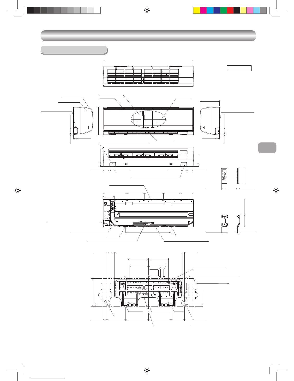
DIMENSION
DIMENSION
Indoor Unit
Unit : Inch (mm)
2-13/16(72) 3-1/16(78)
2-9/16(65)
9-1/4(235)
8-7/16(215)
2-13/16(72)
9-1/4(235)
8-7/16(215)
2-9/16(65)
9/32(7)
8-15/16(228)
1-15/16(50) 1-15/16(50)
1-15/16(50)
2"(50)
3-1/16(78)
30-15/16(786)
12-19/32(320)
41-5/16(1050)
9/32(7)
1(23) 3-11/32(85)
1-9/16(40)
12-19/32(320)
1-9/16(40)
Front panel
Knockout for leftward
piping
Air fi lter
Air inlet
Heat exchanger
Knockout for rightward
piping
Knockout for bottom leftward piping
Knockout for bottom rightward piping
Conduit hole (Ø7/8(22) hole)
Connecting pipe (19-9/32(0.49m))
(Flare Ø1/4(6.35))
Drain hose (19-11/16(0.5m))
Connecting pipe (15-5/16(0.39m))
Flare Ø1/2(12.70)
For stud bold (Ø2-1/4(6))
8-15/32(215.5)
Hanger
Hanger
Center line
Installation plate outline
Grille Inlet
2-7/8(73.5)
2-7/8(73.5)
Air outlet
Hanger
Hanger
Hanger
10-5/16(262.5) 10-5/16(262.5)
Outline of indoor unit
For stud bold (Ø5/16(8)~Ø13/32(10))
10.9"(278) 7.9"(200) 8.7"(222) 7.9"(200) 5.9"(150)
20.7"(525)
5.2"(132)
1-9/16(47) 6-1/32(154) 4-9/32(109)
Installation plate hanger
Minimum
distance
to wall
Minimum
distance
to wall
Minimum
distance
to wall
6-11/16(170)or more
6-11/16(170)or more
2-9/16(65)or more
Wireless remote controller
Remote controller holder
31/32 (26)
3/4 (19)
2-15/32 (63)
2-3/16 (56)
4-29/32 (125)
6-3/4 (157)
1110651824-1 EN.indd 11110651824-1 EN.indd 1 11/13/13 2:02 PM11/13/13 2:02 PM
2-23/32 (69)
)572( 8/7-01
3-17/32 (90)
3-17/32 (90)
23-5/8 (
600
)
17-5/32 (
436
)
)023( 23/91-21
4-1/4 (
108
)
4-15/16 (
125
)
( 8/3-3
68
)
( 61/9-4
611
)
A
B
13-1/2 (342)
( 61/11-12
055
)
11-7/16 (
290
)
( 2
3/3-2
35
)
(
23/5
1
3
88
)
( 6
1/9-5
141
)
1-27/64 (36)
1-31/32 (50)
(R15)
R19/32
)023( 23/91-21
23-5/8 (600)
)603( 46/3-21
1-27/64 (36)
1-31/32 (50)
R19/32 (R15)
23-5/8 (600)
)023( 23/91-21
)603( 4
6/3-21
23-5/8 (
600
)
)
0
23(
23/9
1
-21
2
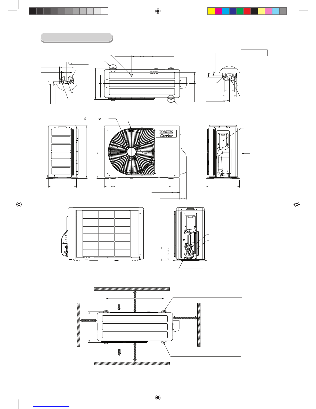
Ø1 (Ø25) Water Drain Outlet
Detail-A (Rear Leg)
R7/32
(R5.5)
Ø1/4 Hole
(Ø6) Hole
Ø1/4 Hole
(Ø6) Hole
Ø7/16x9/16 Oval-Hole
(Ø11x14) Oval-Hole
Detail-B (Front Leg)
COVER
PACKED VALVE
View Z
WIRE GUARD
View Z
Liquid side
(Flare Nut : Ø1/4 (Ø6.35))
Gas side
(Flare Nut : Ø1/2 (Ø12.7))
Service Port
Air Inlet
Air Outlet
3-15/16 or more
(100 mm or more)
23-5/8 or more
(600 mm or more)
2-R7/32x43/64L (R5.5x17L) U-Shape
(For Ø5/16~ Ø13/32 (Ø8~ Ø10) Anchor Bolt)
2-Ø7/16x9/16 (Ø11x14) Oval-Hole
(For Ø5/16~Ø13/32 (Ø8~Ø10) Anchor Bolt)
3-15/16 Inch or more
(100 mm or more)
23-5/8 Inch or more
(600 mm or more)
Unit : Inch (mm)
Outdoor Unit
1110651824-1 EN.indd 21110651824-1 EN.indd 2 11/13/13 2:02 PM11/13/13 2:02 PM
EN
SI
3
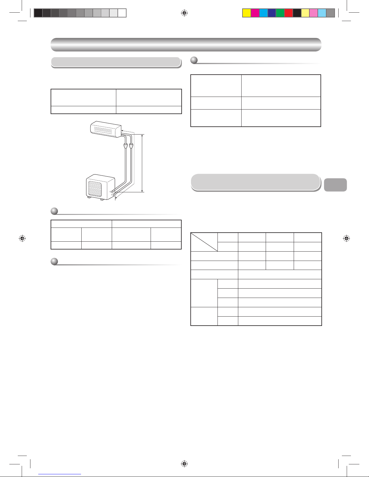
Piping (Field supplied)
• Minimum refrigerant line length between the outdoor unit and indoor unit is
6.6ft. (2m).
• Maximum pipe lengths
SYSTEM REQUIREMENTS
SYSTEM REQUIREMENTS
Allowable
Pipe length T
(ft (m))
Height difference
(Indoor – Outdoor H)
(ft (m))
66 (20) 33 (10)
Refrigerant pipe sizes
HT
Insulation
Both lines need to be insulated. Use a minimum 5/16 in (8mm) wall
thickness.
Refrigerant charge
Unit : ft (m)
Refrigerant charge
Length of refrigerant Pipe
connected to Indoor/
outdoor unit
Additional refrigerant
6.6-50
(2-15m)
None
50-66
(15-20m)
Add 0.22oz/ft (20g/m) of
Refrigerant for piping that exceeds
50ft (15m) up to 66ft (20m)
* Caution during addition of refrigerant
Max. amount of additional refrigerant is 0.22 lbs (100g).
Charge the system accurately. Overcharging may cause serious trouble
to the compressor.
* Minimum refrigerant pipe is 6.6ft (2m).
Using pipe shorter than that may cause a malfunction of the compressor
or other components.
• The power supply shall be connected to the outdoor unit by 3 wires.
• The connecting cable between the indoor unit and outdoor unit needs to
have 4 wires. This cable provides the power for the indoor unit and the
communication signal between the outdoor unit and indoor unit.
• Consult local building codes, NEC (National Electrical Code) or CEC
(Canadian Electrical Code) for special requirements.
• The following are the electrical requirements.
Power supply Connection and
Connecting Cable
Liquid side Gas side
Outer Diameter
In. (mm)
Thickness
In. (mm)
Outer diameter
In. (mm)
Thickness
In. (mm)
Ø1/4 (6.35) 0.03 (0.8) Ø1/2 (12.70) 0.03 (0.8)
Product
Model
Item
FCU RAS-15EK Series RAS-17EK Series RAS-22EK Series
CDU RAS-15EA Series RAS-17EA Series RAS-22EA Series
MCA 13 13 15
MOCP (MAX Fuse/CB) 20 20 25
Breaker 15A
Power supply
cord
(Not provide)
Connect to
FCU/CDU
CDU
No. of Core 3 (L1, L2, i)
Size AWG14
Interconnecting
cable between
FCU & CDU
(Not provide)
No. of Core 4 (L1, L2, S, i)
Size AWG14
MCA = Minimum Circuit Amps
MOCP = Maximum Over Protection Device Amps.
1110651824-1 EN.indd 31110651824-1 EN.indd 3 11/13/13 2:02 PM11/13/13 2:02 PM
 Loading...