

Toshiba Carrier RAS-09 12EK, Carrier RAS-12EK, Carrier RAS-09 12EA, Carrier RAS-09EK, Carrier RAS-09EA Installation Manual
...
ENGLISH
ESPAÑOL
FRANÇAIS
Indoor unit
RAS-09, 12EK Series
Outdoor unit
RAS-09, 12EA Series
AIR CONDITIONER (SPLIT TYPE)
INSTALLATION MANUAL
1110251291-1
1110251291-1 EN.indd 11110251291-1 EN.indd 1 11/13/13 2:52 PM11/13/13 2:52 PM

CONTENTS
DIMENSION .................................................................................................1
SYSTEM REQUIREMENTS .........................................................................3
Piping (Field supplied) ..............................................................................3
Power supply Connection and Connecting Cable ....................................3
PRECAUTIONS FOR SAFETY ....................................................................4
INSTALLATION DIAGRAM OF INDOOR AND OUTDOOR UNITS ............6
Field Supplied Installation Parts ...............................................................6
OUTDOOR UNIT ..........................................................................................7
Installation Location ..................................................................................7
Precautions about Installation in Regions with Snowfall and
Cold Temperatures ...................................................................................7
Refrigerant Piping Connection ..................................................................7
Wiring Connection ....................................................................................7
Electrical Work ..........................................................................................7
INDOOR UNIT ..............................................................................................8
Installation Location ..................................................................................8
Cutting a Hole and Mounting the mounting Plate .....................................8
Wiring Connection ....................................................................................9
Piping and Drain Hose Installation ...........................................................9
Indoor Unit Fixing ...................................................................................10
Drainage ................................................................................................. 11
Remote Control A-B Selection ................................................................ 11
EVACUATING ............................................................................................ 11
Evacuating ............................................................................................. 11
OTHERS .....................................................................................................12
Gas Leak Test .........................................................................................12
Test Operation .......................................................................................12
Auto Restart Setting ..............................................................................12
Troubleshooting (Check Point) ..............................................................12
EN
CONTENIDOS
ES
DIMENSIONES ............................................................................................1
REQUISITOS DE INSTALACIÓN ................................................................3
Tuberías (Suministradas específi camente) ..............................................3
Conexión de la fuente de alimentación y cable ........................................3
PRECAUCIONES SOBRE SEGURIDAD ....................................................4
DIAGRAMA DE INSTALACIÓN DE LA UNIDAD INTERIOR Y EXTERIOR
..6
Piezas de Instalación Opcional ...............................................................6
UNIDAD EXTERIOR ....................................................................................7
Situación de Instalación ............................................................................7
Precauciones sobre Instalación en Regiones con Nieve y
Temperaturas Frías ..................................................................................7
Conexión de la Tubería Refrigerante ........................................................7
Conexión de Cables .................................................................................7
Trabajo Eléctrico ......................................................................................7
UNIDAD INTERIOR .....................................................................................8
Situación de Instalación ............................................................................8
Corte de un Orifi cio y Montaje de la Placa de Montaje ............................8
Conexión de Cables .................................................................................9
Instalación la Tubería y el Tubo de Desagüe ..........................................9
Instalación de la Unidad Interior .............................................................10
Drenaje ..................................................................................................11
Mando a distancia A-B Selección ...........................................................11
EVACUACIÓN ............................................................................................ 11
Evacuación ............................................................................................11
OTROS .......................................................................................................12
Comprobación de Fugas ........................................................................12
Prueba de Operación ............................................................................12
Ajuste de Reinicio Automático ...............................................................12
Troubleshooting (Check Point) ..............................................................12
SOMMAIRE
DIMENSIONS ...............................................................................................1
CONFIGRATION SYSTEME REUQISE .......................................................3
Tuyauterie (Fournie sur chantier) .............................................................3
Connexion de la source d’alimentation et du câble de connexion ............3
MESURES DE SÉCURITÉ ...........................................................................4
PLAN D’INSTALLATION DES UNITÉS INTÉRIEURE ET EXTÉRIEURE ..6
Pièces d’Installation en Option ................................................................6
UNITÉ EXTÉRIEURE ...................................................................................7
Lieu d’Installation ......................................................................................7
Précautions à prendre pour l’installation dans les régions sujettes aux
chutes de neige et aux températures froides ...........................................7
Connexion du Tuyau Réfrigérant ..............................................................7
Connexion des Câbles .............................................................................7
Travaux Electriques .................................................................................7
UNITÉ INTÉRIEURE ....................................................................................8
Lieu d’Installation ......................................................................................8
Ouverture du trou et montage de la plaque de montage ..........................8
Connexion des Câbles .............................................................................9
Installation de la Conduite et du Tuyau de Purge ....................................9
Installation de l’Unité Intérieure ..............................................................10
Drainage ................................................................................................11
Sélection de télécommande A-B ............................................................11
EVACUATION ............................................................................................ 11
Evacuation ............................................................................................. 11
AUTRES .....................................................................................................12
Test de Fuite Gaz ...................................................................................12
Opération du Test ..................................................................................12
Réglage de la Remise en Marche Automatique ....................................12
Troubleshooting (Check Point) ..............................................................12
FR
1110251291-1 EN.indd 21110251291-1 EN.indd 2 11/13/13 2:52 PM11/13/13 2:52 PM
EN
SI
1
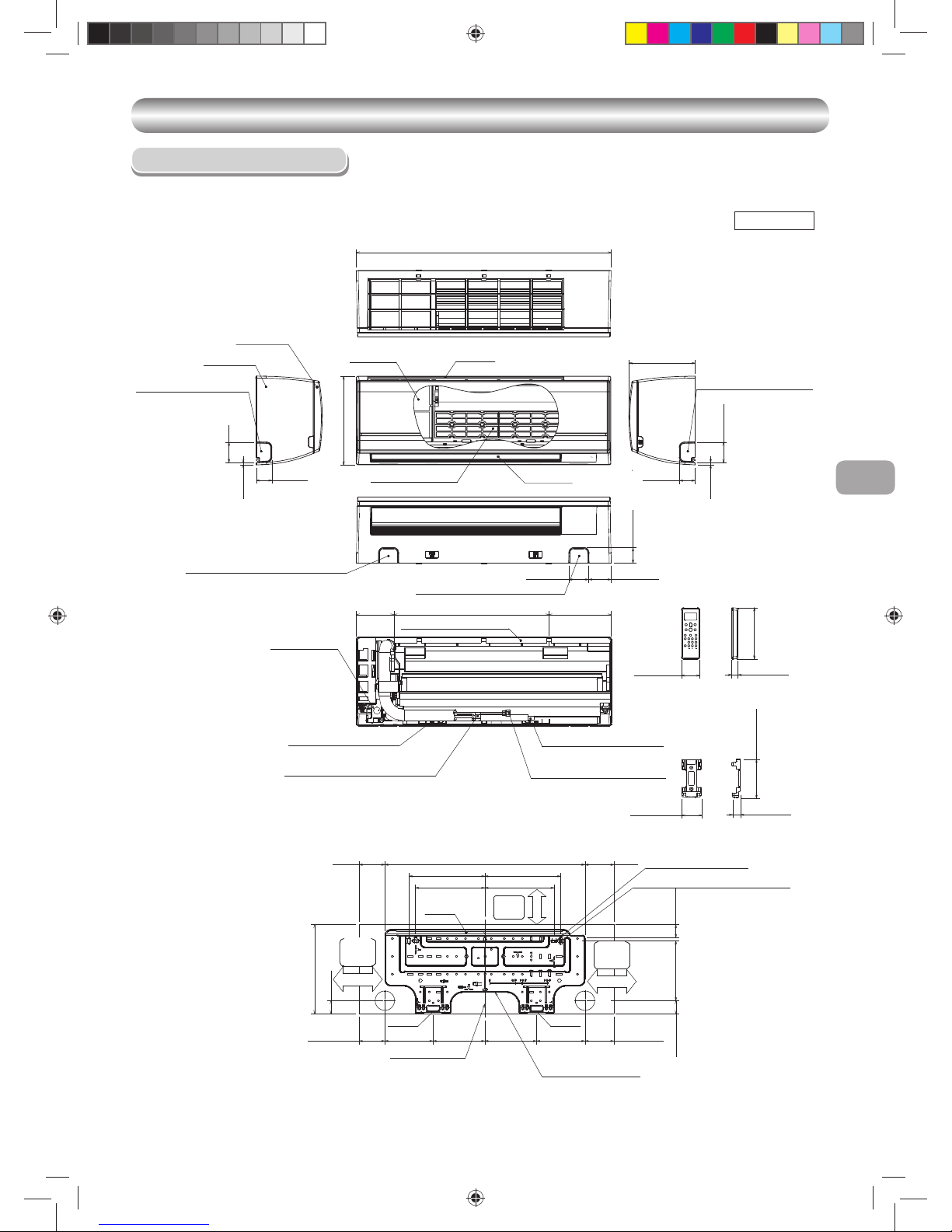
DIMENSION
DIMENSION
Indoor Unit
Unit : Inch (mm)
2-15/32(63)
7-15/32(190)
6-5/16(161) 5-1/2(150)
10-13/16(275)
1-9/16(40)
1-9/16(40)
1-3/4(45)
7-19/32(193)18-7/8(480)
2-7/16(62) 2-11/16(69)
1-7/8(48)
2-15/32(63)
9/32(7)
1-7/8(48)
4-9/16(116)
10-25/32(275)
1-7/8(48)
9/32(7)
24-7/16(621)
8-1/16(205)
31-1/8(790)
8-7/16(215)
9-1/4(235)
9-1/4(235)
8-7/16(215)
6-5/16(161)5-1/2(150)
Front panel
Knockout for leftward piping
Air fi lter Air inlet
Heat exchanger
Knockout for rightward piping
Knockout for bottom leftward piping
Knockout for bottom rightward piping
Installation plate hanger
Conduit hole
(Ø7/8(22) hole)
Connecting pipe (18-5/8(0.40m))
(Flare Ø1/4(6.35))
Installation plate hanger
Connecting pipe (13-25/32(0.35m))
(Flare Ø3/8(9.52))
Wireless remote controller
Drain hose (19-11/16(0.50m))
Remote controller holder
3-5/16(84.5)
3-5/16(84.5)
3-5/16(84.5)3-5/16(84.5)
Hanger
Hanger
Hanger
Center line
Installation plate outline
Minimum
distance
to wall
Minimum
distance
to wall
Minimum
distance
to wall
6-11/16(170)or more
6-11/16(170)or more
2-9/16(65)or more
Grille Inlet
Air outlet
For stud bold (Ø2-1/4(6))
For stud bold (Ø5/16(8)~Ø13/32(10))
31/32 (26)
3/4 (19)
2-15/32 (63)
2-3/16 (56)
4-29/32 (125)
6-3/4 (157)
1110251291-1 EN.indd 11110251291-1 EN.indd 1 11/13/13 2:52 PM11/13/13 2:52 PM
2-23/32 (69)
)572( 8/7-01
3-17/32 (90)
3-17/32 (90)
23-5/8 (
600
)
17-5/32 (
436
)
)023( 23/91-21
4-1/4 (
108
)
4-15/16 (
125
)
( 8/3-3
68
)
( 61/9-4
611
)
A
B
13-1/2 (342)
( 61/11-12
055
)
11-7/16 (
290
)
( 2
3/3-2
35
)
(
23/5
1
3
88
)
( 6
1/9-5
141
)
1-27/64 (36)
1-31/32 (50)
(R15)
R19/32
)023( 23/91-21
23-5/8 (600)
)603( 46/3-21
1-27/64 (36)
1-31/32 (50)
R19/32 (R15)
23-5/8 (600)
)023( 23/91-21
)603( 4
6/3-21
23-5/8 (
600
)
)
0
23(
23/9
1
-21
2
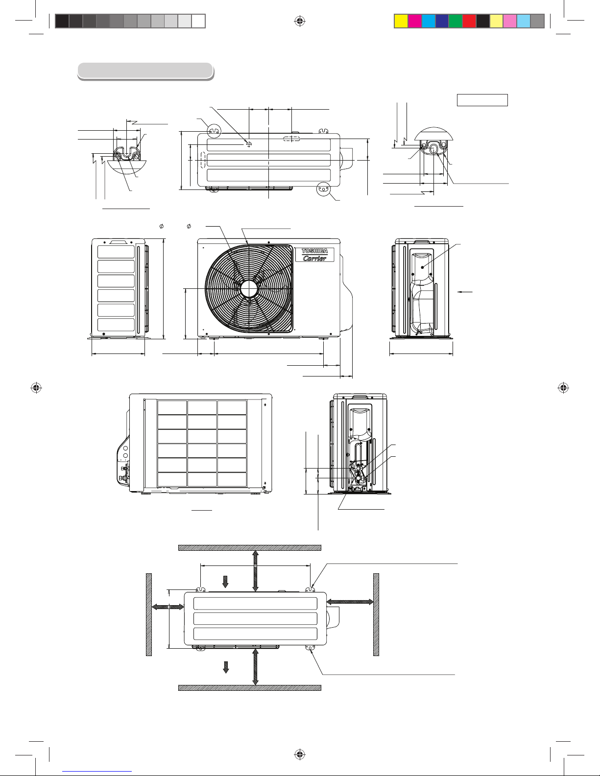
Ø1 (Ø25) Water Drain Outlet
Detail-A (Rear Leg)
R7/32
(R5.5)
Ø1/4 Hole
(Ø6) Hole
Ø1/4 Hole
(Ø6) Hole
Ø7/16x9/16 Oval-Hole
(Ø11x14) Oval-Hole
Detail-B (Front Leg)
COVER
PACKED VALVE
View Z
WIRE GUARD
View Z
Liquid side
(Flare Nut : Ø1/4 (Ø6.35))
Gas side
(Flare Nut : Ø3/8 (Ø9.52))
Service Port
Air Inlet
Air Outlet
3-15/16 or more
(100 mm or more)
23-5/8 or more
(600 mm or more)
2-R7/32x43/64L (R5.5x17L) U-Shape
(For Ø5/16~ Ø13/32 (Ø8~ Ø10) Anchor Bolt)
2-Ø7/16x9/16 (Ø11x14) Oval-Hole
(For Ø5/16~Ø13/32 (Ø8~Ø10) Anchor Bolt)
3-15/16 Inch or more
(100 mm or more)
23-5/8 Inch or more
(600 mm or more)
Unit : Inch (mm)
Outdoor Unit
1110251291-1 EN.indd 21110251291-1 EN.indd 2 11/13/13 2:52 PM11/13/13 2:52 PM
EN
SI
3
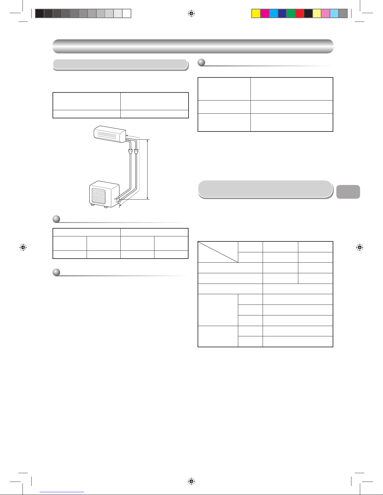
Piping (Field supplied)
• Minimum refrigerant line length between the outdoor unit and indoor unit is
6.6ft. (2m).
• Maximum pipe lengths
SYSTEM REQUIREMENTS
SYSTEM REQUIREMENTS
Allowable
Pipe length T
(ft (m))
Height difference
(Indoor – Outdoor H)
(ft (m))
66 (20) 33 (10)
Refrigerant pipe sizes
HT
Liquid side Gas side
Outer Diameter
In. (mm)
Thickness
In. (mm)
Outer diameter
In. (mm)
Thickness
In. (mm)
Ø1/4 (6.35) 0.03 (0.8) Ø3/8 (9.52) 0.03 (0.8)
Insulation
Both lines need to be insulated. Use a minimum 5/16 in (8mm) wall
thickness.
Refrigerant charge
Unit : ft (m)
Refrigerant charge
Length of refrigerant Pipe
connected to Indoor/
outdoor unit
Additional refrigerant
6.6-50
(2-15m)
None
50-66
(15-20m)
Add 0.22oz/ft (20g/m) of
Refrigerant for piping that exceeds
50ft (15m) up to 66ft (20m)
* Caution during addition of refrigerant
Max. amount of additional refrigerant is 0.22 lbs (100g).
Charge the system accurately. Overcharging may cause serious trouble
to the compressor.
* Minimum refrigerant pipe is 6.6ft (2m).
Using pipe shorter than that may cause a malfunction of the compressor
or other components.
• The power supply shall be connected to the outdoor unit by 3 wires.
• The connecting cable between the indoor unit and outdoor unit needs to
have 4 wires. This cable provides the power for the indoor unit and the
communication signal between the outdoor unit and indoor unit.
• Consult local building codes, NEC (National Electrical Code) or CEC
(Canadian Electrical Code) for special requirements.
• The following are the electrical requirements.
Power supply Connection and
Connecting Cable
Product
Model
Item
FCU RAS-09EK Series RAS-12EK Series
CDU RAS-09EA Series RAS-12EA Series
MCA 10 13
MOCP (MAX Fuse/CB) 15 20
Breaker 15A
Power supply cord
(Not provide)
Connect to
FCU/CDU
CDU
No. of Core 3 (L1, L2, i)
Size AWG14
Interconnecting
cable between FCU
& CDU (Not provide)
No. of Core 4 (L1, L2, S, i)
Size AWG14
MCA = Minimum Circuit Amps
MOCP = Maximum Over Protection Device Amps.
1110251291-1 EN.indd 31110251291-1 EN.indd 3 11/13/13 2:52 PM11/13/13 2:52 PM

4
PRECAUTIONS FOR SAFETY
PRECAUTIONS FOR SAFETY
New refrigerant air conditioner installation
CAUTION
• THIS AIR CONDITIONER USES THE NEW HFC REFRIGERANT (R410A), WHICH DOES NOT DESTROY THE OZONE LAYER.
R410A refrigerant is affected by impurities such as water and oils because the pressure of R410A refrigerant is approx. 1.6 times of refrigerant R22.
ALSO NEW OILS ARE USED WITH R410A, THUS ALWAYS USE NEW REFRIGERANT PIPING AND DO NOT ALLOW MOISTURE OR DUST TO
ENTER THE SYSTEM.
To avoid mixing refrigerant and refrigerant machine oil, the sizes of charging port on the main unit is different than those used on R22 machines and
different tools will be required.
• EQUIPMENT DAMAGE HAZARD
Failure to follow this caution may result in equipment damage or improper operation.
Do not bury more than 36 in. (914 mm) of refrigerant pipe in the ground. If any section of pipe is buried, there must be a 6 in. (152 mm) vertical rise to
the valve connections on the outdoor units. If more than the recommended length is buried, refrigerant may migrate to the cooler buried section during
extended periods of system shutdown. This causes refrigerant slugging and could possibly damage the compressor at start-up.
DANGER
• FOR USE BY QUALIFIED PERSONS ONLY.
• TURN OFF MAIN POWER SUPPLY BEFORE ATTEMPTING ANY ELECTRICAL WORK. MAKE SURE ALL POWER SWITCHES ARE OFF.
FAILURE TO DO SO MAY CAUSE ELECTRIC SHOCK.
• CONNECT THE CONNECTING CABLE CORRECTLY. IF THE CONNECTING CABLE IS CONNECTED WRONGLY, ELECTRIC PARTS MAY BE
DAMAGED.
• CHECK THAT THE EARTH WIRE IS NOT BROKEN OR DISCONNECTED BEFORE INSTALLATION.
• DO NOT INSTALL THE UNIT NEAR CONCENTRATIONS OF COMBUSTIBLE GAS OR GAS VAPORS.
FAILURE TO FOLLOW THIS INSTRUCTION CAN RESULT IN FIRE OR EXPLOSION.
• TO PREVENT OVERHEATING THE INDOOR UNIT AND CAUSING A FIRE HAZARD, PLACE THE UNIT WELL AWAY (MORE THAN 2 M) FROM
HEAT SOURCES SUCH AS RADIATORS, HEATERS, FURNACE, STOVES, ETC.
• WHEN RELOCATING THE AIR CONDITIONER, BE VERY CAREFUL NOT TO MIX THE SPECIFIED REFRIGERANT (R410A) WITH ANY OTHER
GASEOUS BODY INTO THE REFRIGERATION CYCLE. IF AIR OR ANY OTHER GAS IS MIXED WITH THE REFRIGERANT, THE GAS PRESSURE
IN THE REFRIGERATION CYCLE BECOMES ABNORMALLY HIGH AND IT RESULTINGLY CAUSES BURST OF THE PIPE AND INJURIES ON
PERSONS.
• IN THE EVENT OF REFRIGERANT LEAKAGE DURING INSTALLATION, ALLOW FRESH AIR INTO THE ROOM IMMEDIATELY. IF THE
REFRIGERANT GAS IS HEATED BY FIRE OR OTHER MEAN, IT GENERATES POISONOUS GAS.
Installing, staring up, and servicing air-conditioning equipment can be hazardous due to system pressures, electrical components, and equipment location
(roofs, elevated structures, etc.).
Only trained, qualifi ed installers and service mechanics should install, start-up, and service this equipment.
Untrained personnel can perform basic maintenance functions such as cleaning coils. All other operations should be performed by trained service personnel.
When working on the equipment, observe precautions in the literature and on tags, stickers, and labels attached to the equipment.
Follow all safety codes, Wear safety glasses and work gloves. Keep quenching cloth and fi re extinguisher nearby when brazing. Use care in handling,
rigging, and setting bulky equipment.
Read these instructions thoroughly and follow all warnings or cautions included in literature and attached to the unit. Consult local building codes and
National Electrical Code (NEC) for special requirements. Recognize safety information. This is the safety-alert symbol å. When you see this symbol on
the unit and in instructions or manuals, be alert to the potential for personal injury. Understand these signal words: DANGER, WARNING, and CAUTION.
These words are used with the safety-alert symbol.
DANGER identifi es the most serious hazards which will result in severe personal injury or death. WARNING signifi es hazards which could result in personal
injury or death. CAUTION is used to identify unsafe practices which would result in minor personal injury or product and property damage. NOTE is used to
highlight suggestions which will result in enhanced installation, reliability, or operation.
• Before installation, please read these precautions for safety carefully.
• Be sure to follow the precautions provided here to avoid safety risks. The symbols and their meanings are shown below.
1110251291-1 EN.indd 41110251291-1 EN.indd 4 11/13/13 2:52 PM11/13/13 2:52 PM

EN
SI
5
CAUTION
• Exposure of unit to water or other moisture before installation could result in electric shock. Do not store it in a wet basement or expose to rain or water.
• After unpacking the unit, examine it carefully for possible damage. Report any damages to your distributor.
• Do not install in a place that can increase the vibration of the unit. Do not install in a place that can amplify the noise level of the unit or where noise and
discharged air might disturb neighbors.
• Please read this installation manual carefully before installing the unit. It contains further important instructions for proper installation.
• This appliance must be connected to the main power supply by means of a circuit breaker depending on the place where the unit is installed. Failure to do
so may cause electrical shock.
• Follow the instructions in this installation manual to arrange the drain pipe for proper drainage from the unit. Ensure that drained water is discharged.
Improper drainage can result in water leakage, causing water damage to furniture.
• Tighten the fl are nut with a torque wrench using the prescribed method. Do not apply excess torque. Otherwise, the nut may crack after a long period of
usage and it may cause the leakage of refrigerant.
• Wear gloves (heavy gloves such as cotton gloves) for installation work. Failure to do so may cause personal injury when handling parts with sharp edges.
• Do not touch the air intake section or the aluminum fi ns of the outdoor unit. It may cause injury.
• Do not install the outdoor unit in a place which can be a nest for small animals. Small animals could enter and contact internal electrical parts, causing a
failure or fi re.
• Request the user to keep the place around the unit tidy and clean.
• Make sure to conduct a trial operation after the installation work, and explain how to use and maintain the unit to the customer in accordance with the
manual. Ask the customer to keep the operation manual along with the installation manual.
• The manufacturer shall not assume any liability for the damage caused by not observing the description of this manual.
WARNING
• ELECTRICAL SHOCK HAZARD
Failure to follow this warning could result in personal injury or death.
Main electrical disconnect switch must be in the OFF position before installing, modifying, or servicing the system. There may be more than 1 disconnect
switch. Lock out and tag switch with a suitable warning label.
• Never modify this unit by removing any of the safety guards or bypassing any of the safety interlock switches.
• Installation work must be performed by qualifi ed personnel only.
• Specifi ed tools and pipe parts for model R410A are required, and installation work must be done in accordance with the manual. HFC type refrigerant
R410A has 1.6 times more pressure than that of conventional refrigerant (R22). Use the specifi ed pipe parts, and ensure correct installation, otherwise
damage and/or injury may be caused. At the same time, water leakage, electrical shock, and fi re may occur.
• Be sure to install the unit in a place that can suffi ciently bear its weight. If the load bearing of the unit is not enough, or installation of the unit is improper,
the unit may fall and result in injury.
• Electrical work must be performed by trained, qualifi ed installers and service mechanics in accordance with the code governing such installation work,
internal wiring regulations, and the manual. A dedicated circuit and the rated voltage must be used. Insuffi cient power supply or improper installation
may cause electrical shock or fi re.
• Use a cabtyre cable to connect wires in the indoor/outdoor units. Midway connection is not allowed. Improper connection or fi xing may cause a fi re.
• Wiring between the indoor unit and outdoor units must be well shaped so that the cover can be fi rmly placed. Improper cover installation may cause
increased heat, fi re, or electrical shock at the terminal area.
• Be sure to use only approved accessories or the specifi ed parts. Failure to do so may cause the unit to fall, water leakage, fi re or electrical shock.
• After the installation work, ensure that there is no leakage of refrigerant gas. If the refrigerant gas leaks out of the pipe into the room and is heated by
fi re or something else from a fan heater, stove or gas range, it causes generation of poisonous gas.
• Make sure the equipment is properly grounded. Do not connect the ground wire to a gas pipe, water pipe, lightning conductor, or telephone earth wire.
Improper earth work may be the cause of electrical shock.
• Do not install the unit where fl ammable gas may leak. If there is any gas leakage or accumulation around the unit, it can cause a fi re.
• Do not select a location for installation where there may be excessive water or humidity, such as a bathroom. Deterioration of insulation may cause
electrical shock or fi re.
• Installation work must be performed following the instructions in this installation manual. Improper installation may cause water leakage, electrical shock
or fi re. Check the following items before operating the unit.
- Be sure that the pipe connection is well placed and there are no leaks.
- Check that the service valve is open. If the service valve is closed, it may cause overpressure and result in compressor damage. At the same time, if
there is a leak in the connection part, it may cause air suction and overpressure, resulting in damage to the unit or injury.
• In a pump-down operation, be sure to stop the compressor unit before removing the refrigerant pipe. If removing the refrigerant pipe while the
compressor is operating with the service valve opened, it may cause air suction and overpressure, resulting in damage to the unit or injury.
• Do not modify the power cable, connect the cable midway, or use a multiple outlet extension cable. Doing so may cause contact failure, insulation
failure, or excess current, resulting in fi re or electrical shock.
• If you detect any damage, do not install the unit. Contact your dealer immediately.
• Do not use any refrigerant different from the one specifi ed for complement or replacement.
Otherwise, abnormally high pressure may be generated in the refrigeration cycle, which may result in a failure or explosion of the product or an injury to
your body.
1110251291-1 EN.indd 51110251291-1 EN.indd 5 11/13/13 2:52 PM11/13/13 2:52 PM
6
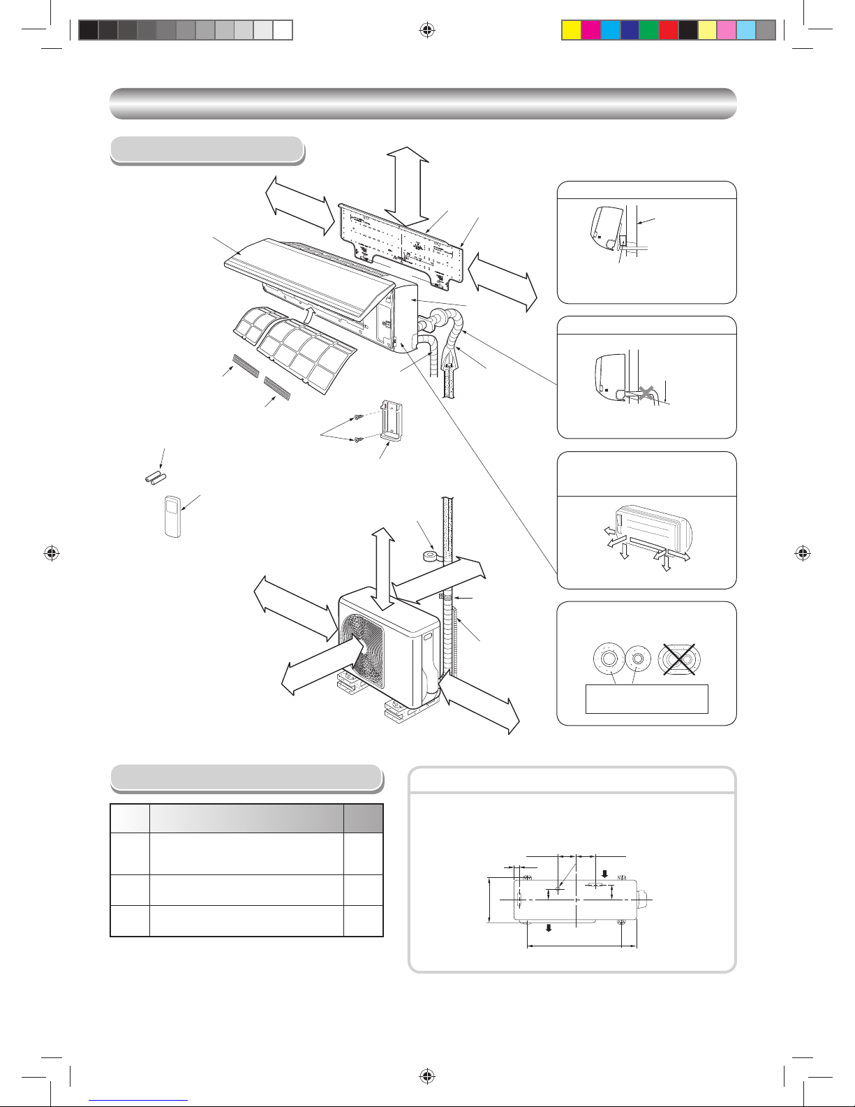
INSTALLATION DIAGRAM OF INDOOR AND OUTDOOR UNITS
INSTALLATION DIAGRAM OF INDOOR AND OUTDOOR UNITS
Part
code
Parts name Q’ty
A
Refrigerant piping
Liquid side : Ø1/4 in. (Ø6.35 mm)
Gas side : Ø3/8 in. (Ø9.52 mm)
One
each
B
Pipe insulating material
(polyethylene foam, 5/16 in. (8 mm) thick)
1
C
Putty, PVC tapes
One
each
Field Supplied Installation Parts
• Secure the outdoor unit with fi xing bolts and nuts if the unit is likely to be
exposed to a strong winds.
• Use Ø5/16 in. (Ø8 mm) or Ø3/8 in. (Ø10 mm) anchor bolts and nuts.
Fixing bolt arrangement of outdoor unit
Insulate the refrigerant pipes separately,
not together.
2
3
8
4
Insert the cushion between the indoor
unit and wall, and tilt the indoor unit for
better operation.
For the rear left and left piping
Wall
Make sure to run the drain hose sloped
downward.
Do not allow the drain hose to get slack.
Cut the piping
hole slightly
sloped downward.
The auxiliary piping can be connected to
the left, rear left, rear right, right, bottom
right or bottom left.
Right
Rear
right
Bottom
right
Rear
left
Bottom left
Left
5/16 in. (8 mm) thick heat
resisting polyethylene foam
1
Batteries
Flat head
wood screw
Remote control holder
Vinyl tape
Apply after carrying
out a drainage test.
Wireless remote control
Saddle
Extension drain hose
(Not available,
provided by installer)
Shield pipe
(Attach to the front panel.)
Air fi lter
Installation
plate
2-9/16 in. (65 mm)
or more
7 in. (170 mm)
or more
3-15/16 in. (100 mm)
or more
3-15/16 in. (100 mm)
or more
23-5/8 in. (600 mm)
or more
23-5/8 in. (600 mm)
or more
6
5
Filter
Filter
Hook
Hook
24 in. (600 mm) or more
only when unobstructed to
the front and both sides.
4-1/4 in.
(108 mm)
1-1/8 in.
(28 mm)
4-15/16 in.
(125 mm)
Ø1 in.
(25 mm)
Air inlet
Air outlet
3-3/8 in.
(86 mm)
4 in.
(102 mm)
12-19/32 in.
(320 mm)
23-5/8 in.
(600 mm)
3-17/32 in.
(90 mm)
7 in. (170 mm)
or more
Conduit
Front
panel
Air inlet grille
CLEARANCES
Remark :
• Details of accessory and installation parts can
be found in the accessory section.
1110251291-1 EN.indd 61110251291-1 EN.indd 6 11/13/13 2:52 PM11/13/13 2:52 PM

EN
SI
7
OUTDOOR UNIT
OUTDOOR UNIT
Installation Location
• A location which provides enough spaces around the outdoor unit as
shown in the diagram above.
• A location which can bear the weight of the outdoor unit and does not
allow an increase in noise level and vibration.
• A location where the operation noise and discharged air do not disturb
your neighbors.
• A location which is not exposed to a strong winds.
• A location free of combustible gases leaks.
• A location which does not block a passage.
• A location where drain water does not cause any problems.
• Depending on snow level, use a fi eld fabricated ice or snow stand.
• When the outdoor unit is to be installed in an elevated position, be sure to
secure its feet as described in the section above.
CAUTION
1. Install the outdoor unit in a location where there are no obstructions
near its air intake or air outlet.
2. When the outdoor units is installed in a place that is always exposed
to strong winds like on the coast or on a high story of a building, use
a fi eld fabricated wind baffl e. To minimize the effect of strong winds,
specially in windy areas, install the unit as shown below.
Strong
wind
90
Refrigerant Piping Connection
1. Make sure you have enough pipe to reach to the indoor unit.
2. Cut the pipe with a pipe cutter.
Flaring
Obliquity Roughness Warp
3. Insert a fl are nut into the pipe and fl are the pipe.
Wiring Connection
1. MOUNT THE OUTDOOR UNIT POWER DISCONNECT.
2. RUN POWER WIRING FROM MAIN BOX TO DISCONNECT PER NEC
AND LOCAL CODES.
3. Remove the valve cover and the cord clamp from the outdoor unit.
4. Fix conduit connector to conduit plate by lock nut and secure it tightly.
Connect the power supply and connecting cables to the terminal block as
shown in the fi gure below and secure it tightly with screws.
5. You should not have extra cables.
6. Secure the power cord and the connecting cable with the cord clamp.
7. Attach the electric parts cover and the valve cover to the outdoor unit.
8. RUN PIPING AND INTERCONNECTING CABLE TO THE INDOOR
UNIT.
Electrical Work
WARNING
ELECTRICAL SHOCK HAZARD
Failure to follow this warning could result in personal injury or death.
The unit cabinet must have an uninterrupted or unbroken ground
to minimize personal injury if an electrical fault should occur. The
ground may consist of electrical wire or metal conduit when installed in
accordance with existing electrical codes.
Make sure main power switch is turned OFF before performing service or
maintenance.
All wiring and connections must comply with NEC, CEC, and local codes.
• Connect all wires to the correct terminal on the wiring terminal blocks.
• Make sure that all connectors are secure.
• Size connectors per the ratings listed in the system requirement section.
• System interconnections should be minimum AWG14.
NOTE
CAUTION
Align the centers of the connecting pipes and tighten the fl are nut as far as
possible with your fi ngers. Then tighten the nut with a two wrenches as show
below.
Tightening connection
Do not apply excess torque. Otherwise, the nut may crack depending on
the conditions.
Outer dia. of copper pipe Tightening torque
Ø1/4 in. (Ø6.35 mm) 10 to 13 lbf.ft (14 to 18 N·m)
Ø3/8 in. (Ø9.52 mm) 24 to 31 lbf.ft (33 to 42 N·m)
• Tightening torque for connection of fl are pipe
The pressure of R410A is higher than
R22. (Approx. 1.6 times.) Therefore
securely tighten the fl are pipes
which connect the outdoor unit and
the indoor unit with the specifi ed
tightening torque using a torque
wrench.
Half union Flare nut
Externally
threaded side
Internally
threaded side
Flare at
indoor unit side
Flare at
outdoor unit side
Use a wrench to secure. Use a torque wrench to tighten.
• Do not use the supplied drain nipple for draining water. Drain the water
from all drain holes directly.
• To protect the outdoor unit from snow accumulation, install a holding
frame, and attach a snow protection hood and plate.
* Do not use a double-stacked design.
Precautions about Installation in Regions
with Snowfall and Cold Temperatures
Snow protection plate
Snow protection hood
Snow accumulation line
Holding frame
At least
19-11/16 in. (500 mm)
Install the unit at least
19-11/16 in. (500 mm)
above the snow
accumulation line.
Anchor
bolts
Front
1110251291-1 EN.indd 71110251291-1 EN.indd 7 11/13/13 2:52 PM11/13/13 2:52 PM

8
Stripping length of the Power supply cord and
Interconnecting cable
L1
L2
L1
L2
S
Interconnecting cable
Power supply cord
Terminal block
Unit : inch (mm)
L1
L2
L1
L2
S
Ground line
Connecting cable Power cord
Ground line
3/8 (10)
3/8 (10)
1-3/16 (30)
2-12/16 (70)
3/8 (10)
3/8 (10)
1-3/16 (30)
1-9/16 (40)
Conduit plate
Connector
Lock nut
Valve cover
NOTE : Interconnecting cable
• Wire type : minimum AWG14
CAUTION
• Wrong wiring connection may cause some electrical parts burn out.
• Be sure to comply with LOCAL CODES.
• Every wire must be connected fi rmly.
• If incorrect or incomplete wiring is carried out, it will cause an ignition
or smoke.
INDOOR UNIT
INDOOR UNIT
Installation Location
• Direct sunlight to the indoor unit’s wireless receiver should be avoided.
• The microprocessor in the indoor unit should not be too close to RF
noise sources.
(For details, see the owner’s manual.)
NOTE
• When drilling a wall that contains a metal lath, wire lath or metal plate, be
sure to use a pipe hole brim ring sold separately.
Cutting a hole
When installing the refrigerant pipes from the rear
After determining the pipe hole position on the mounting plate (➡), drill the
pipe hole Ø2-9/16 in. (Ø65 mm) at a slight downward slant to the outdoor
side.
• A location which provides the clearances around the indoor unit as shown
in the diagram in the “CLEARANCES” section.
• A location where there are no obstacles near the air inlet and outlet
• A location which allows easy installation of the piping to the outdoor unit
• A location which allows the front panel to be opened
• The indoor unit shall be installed such that the top of the indoor unit
comes to at least 6.6 ft (2 m) height. Also avoid putting anything on the top
of the indoor unit.
• A location that will bear the weight of the unit.
CAUTION
80 100 180
The center of the pipe
hole is above the arrow.
Pipe hole
Ø2-9/16 in. (65 mm)
3-15/16 in.
(100 mm)
Cutting a Hole and Mounting the
mounting Plate
Mounting the mounting plate
When the mounting plate is directly mounted to
the wall
1. To hook up the indoor unit, securely fi t the mounting plate onto the wall by
screwing it in the upper and lower parts.
2. To mount the mounting plate on a concrete wall with, anchor bolts, drill the
anchor bolt holes as illustrated in the fi gure shown below.
3. Make sure the mounting plate is leveled.
1
7
Anchor bolt holes
Hook
Hook
Hook
Pipe hole Pipe hole
Mounting
plate
Mounting screw
Weight
Indoor unit
Thread
6.6 ft (2 m) or more
from fl oor
7 in.
(170 mm)
3-11/32 in.
(85 mm)
2-29/64 in.
(62 mm)
3-17/64 in.
(82.5 mm)
1. The supply voltage must be the same as the rated voltage of the air
conditioner.
2. Prepare the power source for exclusive use with the air conditioner.
NOTE : Power supply cord
• Wire type : minimum AWG14
CAUTION
UNIT DAMAGE HAZARD
Failure to follow this caution may result in equipment damage or improper
operation.
Unit failure as a result or of improper line voltage application or excessive
phase imbalance constitutes abuse and may cause damage to electrical
components. Such operation could void any applicable warranty.
1110251291-1 EN.indd 81110251291-1 EN.indd 8 11/13/13 2:52 PM11/13/13 2:52 PM

EN
SI
9
3
1
2
Wiring Connection
1. Open the air inlet grille upward.
2. Remove the screws securing the front panel.
3. Slightly open the lower part of the front panel, then pull the upper part of
the front panel toward you to remove it from the rear plate.
4. Insert the conduit pipe (according to local codes) into the pipe hole on
the wall.
5. Remove the conduit mount by loosening the fi xing screw (Fig. 1)
6. Fix conduit pipe to conduit mount with the lock nut.
7. Pull out the connecting wire through the conduit pipe and process the
wire. (Fig. 3)
8. Take out the wire to the front and fi x it to the terminal block.
Be careful not to mis-wire. (Fig. 2)
9. Firmly tighten the terminal screws to prevent them from loosening.
Tightening torque: 0.9 lbf.ft (1.2 N·m). After tightening, pull the wires
lightly to confi rm that they do not move.
10. Secure the connecting wire with the cord clamp.
11. Fix the conduit mount back to the body by fi xing a screw.
12. Fix the front panel, terminal cover and air inlet grille to the indoor unit.
How to connect the connecting cable
NOTE
• Use stranded wire only.
• Wire type : minimum AWG14
CAUTION
S
L
2
L1
Ground
line
4-5/16 in. (110 mm)
3-5/32 in. (80 mm)
13/16 in. (20 mm)
3/8 in. (10 mm)
• Be sure to refer to the system wiring
diagram located inside the front panel.
• Check local electrical codes and also
any specifi c wiring instructions or
limitations.
Fig. 3
Fig. 2 Wiring
L
1
L
2
S
L
1
L
2
S
Cord clamp
Terminal block
Terminal cover
Screw
Ground line
Screw
Connecting cable
Screw
Front panel
CAUTION
Failure to fi rmly install the unit may result in personal injury and property
damage if the unit falls.
• In case the unit is to be installed in a block, brick, concrete or similar type
walls, make 3/16 in. (5 mm) dia. holes in the wall.
• Insert clip anchors for appropriate mounting screws 7.
NOTE
• Secure four corners and lower parts of the mounting plate with 4 to 6
mounting screws to install it.
7
CAUTION
Installation plate
(Keep horizontal direction.)
3/16 in. (5 mm) dia. hole
Mounting screw
Ø5/32 in. × 1 in.
(Ø4 mm × 25 mm)
Clip anchor
(fi eld supplied parts)
Anchor bolt
Projection
9/16 in. (15 mm)
or less
When installing the mounting plate with a mounting screw, do not use the
anchor bolt holes. Otherwise, the unit may fall down and result in personal
injury and property damage.
Air inlet grille
Front panel
Conduit pipe
Conduit mount
Fixing screw
Lock nut
Interconnecting
cable
Fig. 1 Construction
Piping and Drain Hose Installation
INSULATE BOTH LINES.
Piping and drain hose forming
Rear right
Rear left
Bottom left
Left
Bottom right
Right
Die-cutting
front panel slit
Changing
drain hose
Piping preparation
Right
Rear right
Bottom
right
Rear
left
Bottom left
Left
How to install the air inlet grille on the indoor
unit
• When attaching the air inlet grille,
perform the same process as for
removal but in reverse order.
1110251291-1 EN.indd 91110251291-1 EN.indd 9 11/13/13 2:52 PM11/13/13 2:52 PM

10
Firmly insert the drain hose and drain cap; otherwise, water may leak.
In case of right or left piping
• After making slits of the front panel with a
knife or a making-off pin, cut them with a
pair of nippers or an equivalent tool.
In case of bottom right or bottom left piping
• After making slits of the front panel with a
knife or a making-off pin, cut them with a
pair of nippers or an equivalent tool.
Left-hand connection with piping
• Bend the connecting pipe so that it is laid within 1-5/8 in. (43 mm) above
the wall surface. If the connecting pipe is laid exceeding 1-5/8 in. (43 mm)
above the wall surface, the indoor unit may set on the wall unstably.
When bending the connecting pipe, make sure to use a spring bender to
avoid crushing the pipe.
Bend the connecting pipe within a radius of 1-3/16 in. (30 mm).
To connect the pipe after the unit has been installed (fi gure)
CAUTION
Slit
Slit
80
Liquid side
Gas side
(To the forefront of fl are)
Outward form of indoor unit
R 1-3/16 in. (R 30 mm) (Use polisin
(polyethylene) core or the like for
bending pipe.)
Use the handle of a screwdriver, etc.
6-11/16 in.
(170 mm)
1-5/8 in.
(43 mm)
10-5/8 in.
(270 mm)
How to remove the drain cap
Clip the drain cap with needle-nose
pliers and pull out.
How to fi x the drain cap
1) Insert a hexagon wrench
3/16 in. (4 mm) in the
center head of the cap.
2) Firmly insert the drain cap.
3/16 in.
(4 mm)
No gap
Do not apply lubricating oil
(refrigerant machine oil) when
inserting the drain cap. Application
causes deterioration and drain
leakage from the plug.
Insert a hexagon
wrench 3/16 in.
(4 mm).
How to remove the drain hose
• The drain hose can be removed by removing the
screw securing the drain hose and then pulling out
the drain hose.
• When removing the drain hose, be careful of any
sharp edges the steel plate may have. Sharp
edges can cause injuries.
• To install the drain hose, insert the drain hose
fi rmly until the connection part contacts the heat
insulator, and then secure it with the original
screws.
Heat insulator
Drain hose
NOTE
If the pipe is bent incorrectly, the indoor unit may set on the wall unstably.
After passing the connecting pipe through the pipe hole, connect the
connecting pipes to the refrigerant line and wrap facing tape around them.
CAUTION
• Bind the refrigerant lines (two) and connecting cable with facing tape
tightly. In case of leftward piping and rear-leftward piping, bind the
refrigerant lines (two) only with facing tape.
Indoor unit
Connecting cable
Refrigerant lines
Installation plate
• Carefully arrange pipes such that none of them stick out of the rear
plate of the indoor unit.
• Carefully connect the refrigerant lines and connecting pipes to one
another and cut off the insulating tape wound on the connecting pipe
to avoid double-taping at the joint; moreover, seal the joint with vinyl
tape, etc.
• Check for gas leaks before insulating.
Indoor Unit Fixing
• To detach the indoor unit from the
mounting plate, pull the indoor unit toward
you while pushing its bottom up as shown
in the fi gure.
1
2
1
1. Pass the pipe through the hole in the wall and hook the indoor unit on the
upper hook of the installation plate.
2. Swing the indoor unit to the right and left to confi rm that it is fi rmly hooked
up to the mounting plate.
3. While pressing the indoor unit onto the wall, hook it to the lower section
of the mounting plate. Pull the indoor unit toward you to confi rm that it is
fi rmly hooked up to mounting plate.
Hook here.
Installation plate
Hook
Press
(unhook)
Push Push
1. Die-cutting front panel slit
With a pair, of nippers, cut out the slit on the leftward or right side of the
front panel for the left or right connection, and the slit on the bottom left or
right side of the front panel for the bottom left or right connection.
2. Changing drain hose
For leftward connection, bottom-leftward connection and rearleftward
connection’s piping, it is necessary to change the drain hose and drain
cap.
1110251291-1 EN.indd 101110251291-1 EN.indd 10 11/13/13 2:52 PM11/13/13 2:52 PM
EN
SI
11
Drainage
1. Run the drain hose slopping downward.
NOTE
• The hole should be made at a slight downward slant on the outdoor side.
• The drain is internally trapped. An external trap is not required.
Do not rise the
drain hose.
Do not form the
drain hose into
a wavy shape.
2 in.
(50 mm)
or more
Do not put the
drain hose end
into water.
Do not put the
drain hose end
in the drainage ditch.
2. Put water in the drain pan and make sure that the water is drained out.
3. When connecting an extension drain hose, insulate it with shield pipe.
Shield pipe
Drain hose
Extension drain hose
Inside the room
Arrange the drain pipe for proper drainage from the unit.
Improper drainage can result in dew-dropping.
This air conditioner has the structure designed
to drain water collected from dew, which forms
on the back of the indoor unit, to the drain pan.
Therefore, do not store the power cord and other
parts at a height above the drain guide.
CAUTION
Wall
Drain
guide
Space for pipes
Remote control
• Place the remote control away from obstacles (such as curtain) that may
block the signal coming from the remote control.
• Do not install the remote control in a place exposed to direct sunlight or
close to a heating source such as a stove.
• Keep the remote control at least 3.3 ft (1 m) apart from the nearest TV set
or stereo equipment. (This is necessary to prevent image disturbances or
noise interference.)
• The location of the remote control should be determined as shown below.
54 °
4
5°
5
7
°
Indoor unit
(Side view)
(Top view)
Indoor unit
Remote
control
Remote
control
Reception
range
Reception range
Remote Control A-B Selection
In case of two systems operating nearby, follow the instructions below to set
the remote control to operate with one indoor unit at a time.
Remote Control B Setup.
1. Press RESET button on the indoor unit to turn the air conditioner ON.
2. Point the remote control at the indoor unit.
3. Push and hold CHK ● button on the Remote Control with the tip of a
pencil. “00” will be shown on the display.
4. Press
MODE
while pushing CHK ●. “B” will show on the display and
“00” will disappear and the air conditioner will turn OFF. B is now
memorized.
Note: 1. Repeat above step to reset Remote Control back to A.
2. Remote Control does not display “A”.
3. Default setting of Remote Control from factory is A.
“B” Display
“00” Display
Evacuating
After the piping has been connected to the indoor unit, you vacuum both
units at once.
Be sure to use a vacuum pump with counter-fl ow prevention function so
that inside oil of the pump does not fl ow backward into pipes of the air
conditioner when the pump stops.
(If oil inside of the vacuum pump enters the air conditioner, which uses
R410A, refrigeration cycle trouble may happen.)
1. Connect the charge hose from the manifold valve to the service port of
the packed valve at the gas side.
2. Connect the charge hose to the port of the vacuum pump.
3. Open fully the low pressure side handle of the manifold valve gauge.
4. Operate the vacuum pump to start evacuating. Perform evacuation for
about 15 minutes if the piping length is 66 feet (20 m). (assuming a
pump capacity of 27 liters per minute) Then confi rm that the compound
pressure gauge reading is –101 kPa (–76 cmHg).
Using a vacuum pump
Evacuate the air in the connecting pipes and in the indoor unit using a
vacuum pump. Do not re-use the refrigerant in the outdoor unit. For details,
see the vacuum pump manual.
VACUUMING
EVACUATING
EVACUATING
Packed valve at
liquid side
Service port (Valve core
(Setting pin))
Packed valve at gas side
Vacuum
pump
Vacuum pump adapter for
counter-fl ow prevention
(For R410A only)
Charge hose
(For R410A only)
Handle Hi
(Keep full closed)
Manifold valve
Pressure gauge
Compound pressure gauge
Handle Lo
Charge hose
(For R410A only)
Connecting pipe
–101 kPa
(–76 cmHg)
5. Close the low pressure side valve handle of the manifold valve gauge.
6. Open fully the valve stem of the packed valves (both gas and liquid
sides).
7. Remove the charging hose from the service port.
8. Securely tighten the caps of packed valves.
1110251291-1 EN.indd 111110251291-1 EN.indd 11 11/13/13 2:52 PM11/13/13 2:52 PM
12
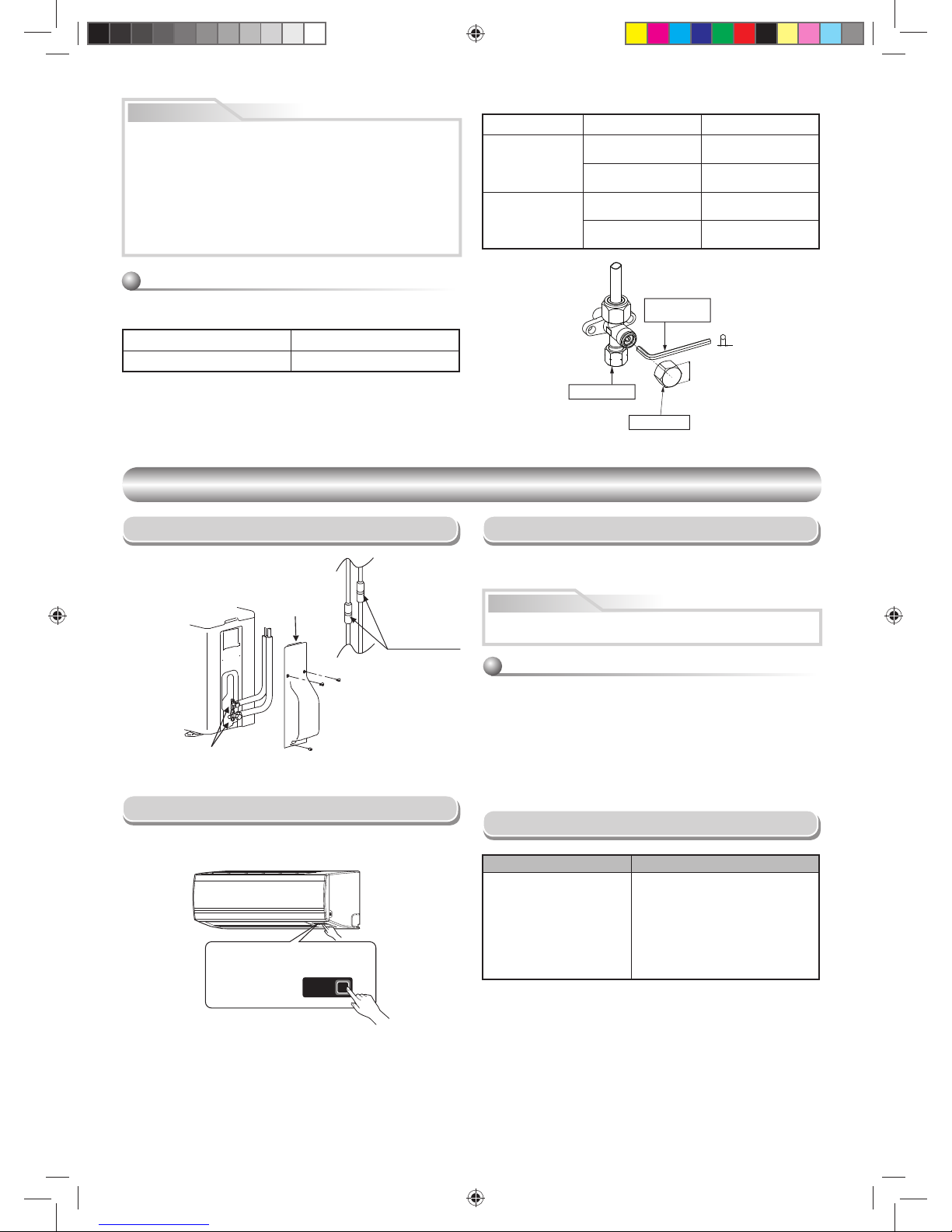
Packed valve handling precautions
• Open the valve stem all the way out, but do not try to open it beyond the
stopper.
• Securely tighten the valve cap with torque in the following table:
Pipe size of Packed Valve Size of Hexagon wrench
1/2 in. (12.7 mm and smallers) A = 3/16 in. (4 mm)
Cap Cap Size (H) Torque
Valve Rod Cap
43/64 in. - 3/4 in.
(H17 - H19)
10 to 13 Ibf.ft
(14~18 N·m)
55/64 in. - 1-3/16 in.
(H22 - H30)
24 to 31 Ibf.ft
(33~42 N·m)
Service Port Cap
35/64 in.
(H14)
37 to 46 Ibf.ft
(50~62 N·m)
43/64 in.
(H17)
10 to 13 Ibf.ft
(14~18 N·m)
A
H
Hexagon wrench
is required.
Service Port Cap
Valve Rod Cap
OTHERS
OTHERS
Gas Leak Test
Test Operation
Troubleshooting (Check Point)
To switch the TEST RUN (COOL) mode, press RESET button for 10 seconds.
(The beeper will make a short beep.)
Auto Restart Setting
The product was shipped with Auto Restart function in the ON position.
Turn it OFF if this function is not required.
How to cancel the Auto Restart
Check the fl are nut
connections for the
gas leak with a gas
leak detector or
soap water.
This product is designed so that after a power failure it can restart
automatically in the same operating mode as before the power failure.
1. Press and hold the RESET button on the indoor unit for 3 seconds to
cancel the ope
ration. (3
beeps will
sound but OPERATION lamp does not
blink)
2. Press and hold the RESET button on the indoor unit for 3 seconds to set
the operation. (3 beeps will sound and OPERATION lamp blink 5 time/
sec for 5 seconds)
• Do not operate ON timer and OFF timer.
Note : Default setting of auto restart operation is ON.
Check places with
fl are nut connections
(indoor unit)
Check places for
the outdoor unit.
Valve cover
Information
RESET
RESET button
The unit does not operate. Cooling or Heating is abnormally low.
• The power main switch is
turned off.
• The circuit breaker is tripped.
• ON timer is set.
• The fi lters are blocked with dust.
• The temperature has been set
improperly.
• Windows or doors are open.
• The air inlet or outlet of the outdoor
unit is blocked.
• The fan speed is too low.
• The operation mode is FAN or DRY.
CAUTION
• 5 IMPORTANT POINTS FOR PIPING WORK.
(1) Take away dust and moisture (inside of the connecting pipes).
(2) Tighten the connections (between pipes and unit).
(3) Evacuate the air in the connecting pipes using a VACUUM PUMP.
(4) Check gas leak (connected points).
(5) Be sure to fully open the packed valves before operation.
• UNIT DAMAGE HAZARD
Failure to follow this caution may result in equipment damage or
improper operation.
Never use the system compressor as a vacuum pump.
1110251291-1 EN.indd 121110251291-1 EN.indd 12 11/13/13 2:52 PM11/13/13 2:52 PM
 Loading...