

Toshiba Carrier MMD-AP0074SPH2UL, Carrier MMD-AP0124SPH2UL, Carrier MMD-AP0154SPH2UL, Carrier MMD-AP0184SPH2UL, Carrier MMD-AP0094SPH2UL Installation Manual
Page 1
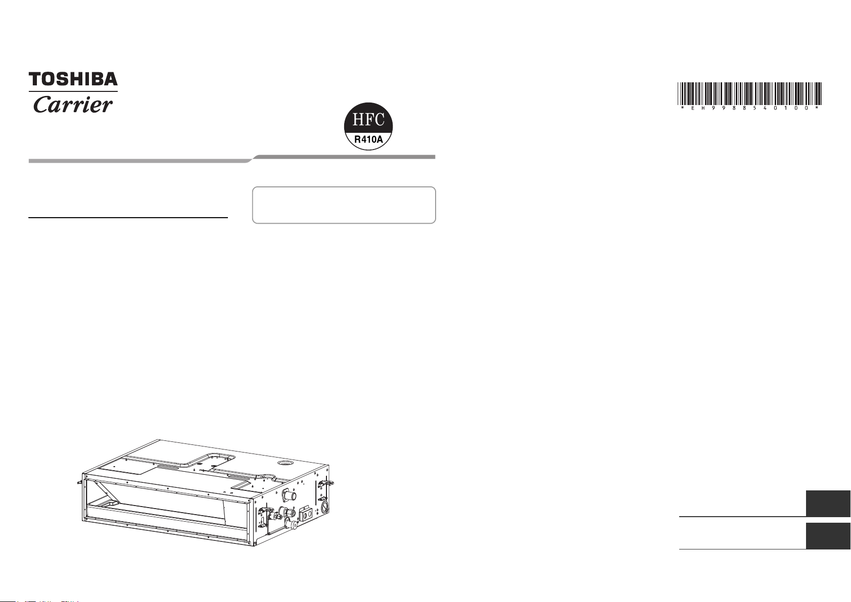
AIR CONDITIONER (MULTI TYPE)
Installation Manual
Indoor Unit
Model name:
Slim Duct Type
MMD-AP0074SPH2UL
MMD-AP0094SPH2UL
MMD-AP0124SPH2UL
MMD-AP0154SPH2UL
MMD-AP0184SPH2UL
For commercial use
Pour usage commercial
Installation Manual 1
Manuel d’installation 22
English
Français
Page 2
–1–
Please read this Installation Manual carefully before installing the Air Conditioner.
• This Manual describes the installation method of the indoor unit.
• For installation of the outdoor unit, follow the Installation Manual attached to the outdoor unit.
ADOPTION OF NEW REFRIGERANT
This Air Conditioner uses R410A an environmentally friendly refrigerant.
Contents
1 Precautions for safety . . . . . . . . . . . . . . . . . . . . . . . . . . . . . . . . . . . . . . . . . . . . . . . . . . 1
2 Accessory parts . . . . . . . . . . . . . . . . . . . . . . . . . . . . . . . . . . . . . . . . . . . . . . . . . . . . . . . 2
3 Selection of installation place. . . . . . . . . . . . . . . . . . . . . . . . . . . . . . . . . . . . . . . . . . . . 3
4 Installation . . . . . . . . . . . . . . . . . . . . . . . . . . . . . . . . . . . . . . . . . . . . . . . . . . . . . . . . . . .5
5 Drain piping . . . . . . . . . . . . . . . . . . . . . . . . . . . . . . . . . . . . . . . . . . . . . . . . . . . . . . . . . .7
6 Duct design. . . . . . . . . . . . . . . . . . . . . . . . . . . . . . . . . . . . . . . . . . . . . . . . . . . . . . . . . . .9
7 Refrigerant piping . . . . . . . . . . . . . . . . . . . . . . . . . . . . . . . . . . . . . . . . . . . . . . . . . . . . 11
8 Electrical connection . . . . . . . . . . . . . . . . . . . . . . . . . . . . . . . . . . . . . . . . . . . . . . . . . . 12
9 Applicable controls . . . . . . . . . . . . . . . . . . . . . . . . . . . . . . . . . . . . . . . . . . . . . . . . . . . 15
10 Test run . . . . . . . . . . . . . . . . . . . . . . . . . . . . . . . . . . . . . . . . . . . . . . . . . . . . . . . . . . . . . 17
11 Troubleshooting . . . . . . . . . . . . . . . . . . . . . . . . . . . . . . . . . . . . . . . . . . . . . . . . . . . . . . 18
1-EN 2-EN
1 Precautions for safety
Installing, starting up, and servicing air--conditioning equipment can be hazardous due to system pressures,
electrical components, and equipment location (roofs, elevated structures, etc.).
Only trained, qualified installers and service mechanics should install, start--up, and service this equipment.
Untrained personnel can perform basic maintenance functions such as cleaning heat exchanger. All other
operations should be performed by trained service personnel.
Before working on the equipment, observe precautions in the literature and on tags, stickers, and labels attached
to the equipment.
Follow all safety codes.Wear safety glasses and work gloves. Keep quenching cloth and fire extinguisher nearby
during brazing. Use care in handling, rigging, and setting bulky equipment.
Read these instructions thoroughly and follow all warnings or cautions included in literature and attached to the
unit. Consult local building codes and National Electrical Code (NEC) for special requirements. Recognize safety
information. This is the safety--alert symbol . When you see this symbol on the unit and in instructions or
manuals, be alert to the potential for personal injury.Understand these signal words: DANGER, WARNING, and
CAUTION. These words are used with the safety--alert symbol.
DANGER identifies the most serious hazards which will result in severe personal injury or death. WARNING
signifies hazards which could result in personal injury or death. CAUTION is used to identify unsafe practices which
may result in minor personal injury or product and property damage. NOTE is used to highlight suggestions which
will result in enhanced installation, reliability, or operation.
The manufacturer shall not assume any liability for the damage caused by not observing the description of this
manual.
WARNING
• Only a qualified installer or service person is allowed to do installation work.
Inappropriate installation may result in water leakage, electric shock or fire.
• Do not use any refrigerant different from the one specified for complement or replacement.
Otherwise, abnormally high pressure may be generated in the refrigeration cycle, which may result in a
failure or explosion of the product or an injury to your body.
• Connect ground wire. (grounding work)
Incomplete grounding may cause an electric shock.
Do not connect ground wires to gas pipes, water pipes, lightning rods or ground wires for telephone wires.
• Turn off all the circuit breaker before attempting any electrical work.
Failure to do so may cause electric shock.
• Install the refrigerant pipe securely during the installation work before operating the air conditioner.
If the air conditioner is operated with the valve open and without the refrigerant pipe, the compressor sucks air and
the refrigeration cycle is overpressurized, which may cause a burst or injury.
• When moving the air conditioner for the installation into another place, do not enter any gaseous matter
other than the specified refrigerant into the refrigeration cycle.
If air or any other gas is mixed in the refrigerant, the gas pressure in the refrigeration cycle becomes abnormally high
and it resultingly causes pipe burst and injuries on persons.
• Perform installation work properly according to the Installation Manual.
Inappropriate installation may result in water leakage, electric shock or fire.
• When the air conditioner is installed in a small room, provide appropriate measures to ensure that the
concentration of refrigerant leakage occur in the room does not exceed the critical level.
• Install the air conditioner securely in a location where the base can sustain the weight adequately.
• Perform the specified installation work to guard against an earthquake.
If the air conditioner is not installed appropriately, accidents may occur due to the falling unit.
• Install the air conditioner at a height 8’ (2.4 m) or more from the floor.
If you insert your hands or others directly into the unit while the air conditioner operates, it is dangerous because you
may contact with revolving fan or active electricity.
• If refrigerant gas has leaked during the installation work, ventilate the room immediately.
If the leaked refrigerant gas comes in contact with fire, noxious gas may generate.
• After the installation work, confirm that refrigerant gas does not leak.
If refrigerant gas leaks into the room and flows near a fire source, such as a cooking range, noxious gas might
generate.
• Electrical work must be performed by a qualified electrician in accordance with the Installation Manual. Use
an exclusive power supply for the air conditioner at the rated voltage.
An insufficient power supply capacity or inappropriate installation may cause fire.
Page 3
• Use the specified wires for wiring connect the terminals. Securely fix them to prevent external forces applied
to the terminals from affecting the terminals.
• Conform to the regulations of the local electric company when wiring the power supply.
• For the refrigerant recovery work (collection of refrigerant from the pipe to the compressor), stop the
compressor before disconnecting the refrigerant pipe.
If the refrigerant pipe is disconnected while the compressor is working with the valve open, the compressor sucks air
and the refrigeration cycle is overpressurized, which may cause a burst or injury.
• Before carrying out the installation, maintenance, repair or removal work, set the circuit breaker to the OFF
position.
Otherwise, electric shocks may result.
• Do not touch the aluminium fin of the unit. You may injure yourself if you do so. If the fin must be touched
for some reason, first put on protective gloves and safety work clothing, and then proceed.
• Install the air conditioner securely in a location where the base can sustain the weight adequately. If the
strength is not enough, the unit may fall down resulting in injury.
• The unit can be accessed from the service panel.
• Install a circuit breaker that meets the specifications in the installation manual and the stipulations in the
local regulations and laws.
• Install the circuit breaker where it can be easily accessed by the agent.
• Under no circumstances the power wire must not be extended. Connection trouble in the places where the
wire is extended may give rise to smoking and/or a fire.
• Upon completion of the installation work, tell the user where the circuit breaker is located. If the user does
not know where the circuit breaker is, he or she will not be able to turn it off in the event that trouble has
occurred in the air conditioner.
CAUTION
• This air conditioner adopts the new HFC refrigerant (R410A) which does not destroy ozone layer.
• The characteristics of R410A refrigerant are; easy to absorb water, oxidizing membrane or oil, and its pressure is
approx. 1.6 times higher than that of refrigerant R22. Accompanied with the new refrigerant, refrigerating oil has also
been changed. Therefore, during installa tion work, be sure that water, dust, former refrigerant, or refrigerating oil does
not enter the refrigerating cycle.
• To prevent charging an incorrect refrigerant and refrigerating oil, the sizes of connecting sections of charging port of
the main unit and installation tools are changed from those for the conventional refrigerant.
• Accordingly the exclusive tools are required for the new refrigerant (R410A).
• For connecting pipes, use new and clean piping designed for R410A, and please care so that water or dust does not
enter.
• Tighten the flare nut with a torque wrench in the specified manner.
Excessive tightening of the flare nut may cause a crack in the flare nut after a long period, which may result in
refrigerant leakage.
• Wear heavy gloves during the installation work to avoid injury.
2 Accessory parts
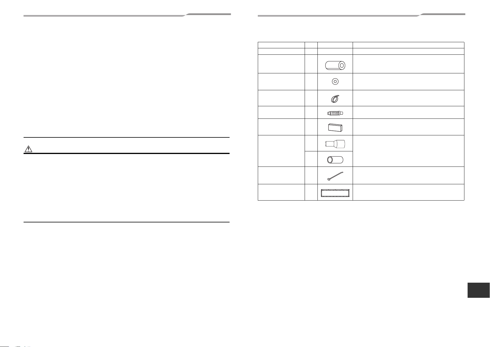
Part name Q’ty Shape Usage
Installation Manual 1 This manual (Hand over to customers)
Heat insulating pipe 2 For heat insulation of pipe connecting section
Washer 8 For hanging-up unit
Hose band 1 For connecting drain pipe
Flexible hose 1 For adjustment of drain pipe centering
Heat insulator 1 For insulating drain connecting section
1
Drain socket
1
Banding band 2 For fixing of pipe connecting heat insulator
Air intake port flange 1 For connecting a duct when air intake is from the back
For connect drain pipe
EN
3-EN 4-EN
–2–
Page 4
–3–
3 Selection of installation place
Avoid installing in the following places
Select a location for the indoor unit where the cool or warm air will circulate evenly.
Avoid installation in the following kinds of locations.
• Saline area (coastal area).
• Locations with acidic or alkaline atmospheres (such as areas with hot springs, factories where chemicals or
pharmaceuticals are made and places where the exhaust air from combustion appliances will be sucked into the
unit).
Doing so may cause the heat exchanger (its aluminum fins and copper pipes) and other parts to become
corroded.
• Locations with atmospheres with mist of cutting oil or other types of machine oil.
Doing so may cause the heat exchanger to become corroded, mists caused by the blockage of the heat
exchanger to be generated, the plastic parts to be damaged, the heat insulators to peel off, and other such
problems to result.
• Locations where vapors from food oils are formed (such as kitchens where food oils are used).
Blocked filters may cause the air conditioner’s performance to deteriorate, condensation to form, the plastic parts
to be damaged, and other such problems to result.
• Places where iron or other metal dust is present. If iron or other metal dust adheres to or collects on the interior
of the air conditioner, it may spontaneously combust and start a fire.
• Locations near obstructions such as ventilation openings or lighting fixtures where the flow of the blown air will
be disrupted (a disruption of the air flow may cause the air conditioner’s performance to deteriorate or the unit to
shut down).
• Locations where an in-house power generator is used for the power supply.
The power line frequency and voltage may fluctuate, and the air conditioner may not work properly as a result.
• On truck cranes, ships or other moving conveyances.
• The air conditioner must not be used for special applications (such as for storing food, plants, precision
instruments or art works).
(The quality of the items stored may be degraded.)
• Locations where high frequencies are generated (by inverter equipment, in-house power generators, medical
equipment or communication equipment).
(Malfunctioning or control trouble in the air conditioner or noise may adversely affect the equipment’s operation.)
• Locations where there is anything under the unit installed that would be compromised by wetness.
(If the drain has become blocked or when the humidity is over 80 %, condensation from the indoor unit will drip,
possibly causing damage to anything underneath.)
• In the case of the wireless type of system, rooms with the inverter type of fluorescent lighting or locations
exposed to direct sunlight.
(The signals from the wireless remote control may not be sensed.)
• Locations where organic solvents are being used.
• The air conditioner cannot be used for liquefied carbonic acid cooling or in chemical plants.
• Location near doors or windows where the air conditioner may come into contact with high-temperature, highhumidity outdoor air.
(Condensation may occur as a result.)
• Locations where special sprays are used frequently.
Installation under high-humidity atmosphere
In some cases including the rainy season, especially inside of the ceiling may become high-humidity atmosphere
(dew-point temperature: 73 °F (22.8 °C) or higher).
1. Installation to inside of the ceiling with tiles on the roof
2. Installation to inside of the ceiling with slated roof
3. Installation to a place where inside of the ceiling is used for pathway to intake the fresh air
4. Installation to a kitchen
• In the above cases, additionally attach the heat insulator to all positions of the air conditioner, which come to
contact with the high-humidity atmosphere. In this case, arrange the side plate (Check port) so that it is easily
removed.
• Apply also a sufficient heat insulation to the duct and connecting part of the duct.
[Reference] Condensation test conditions
Indoor side:
Air volume: Low air volume, operation time 4 hours
80 °F (26.7 °C) dry bulb temperature
75 °F (23.9 °C) wet bulb temperature
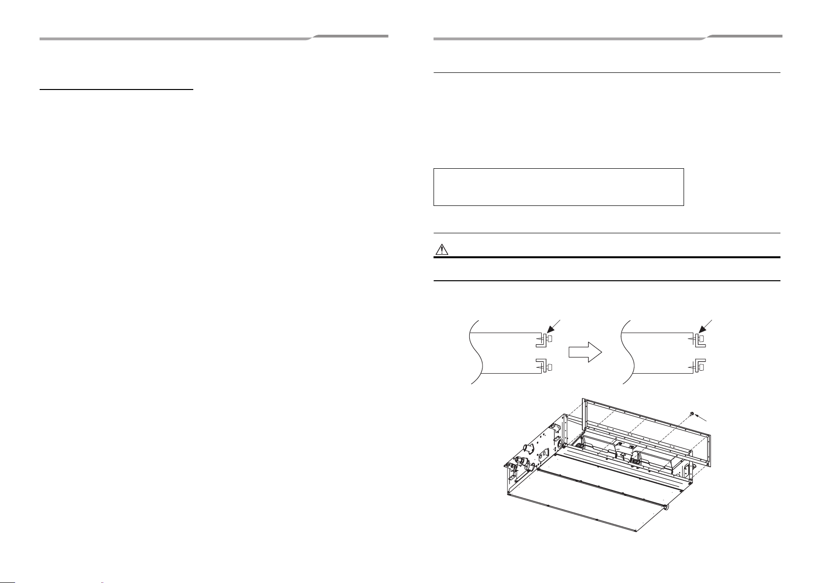
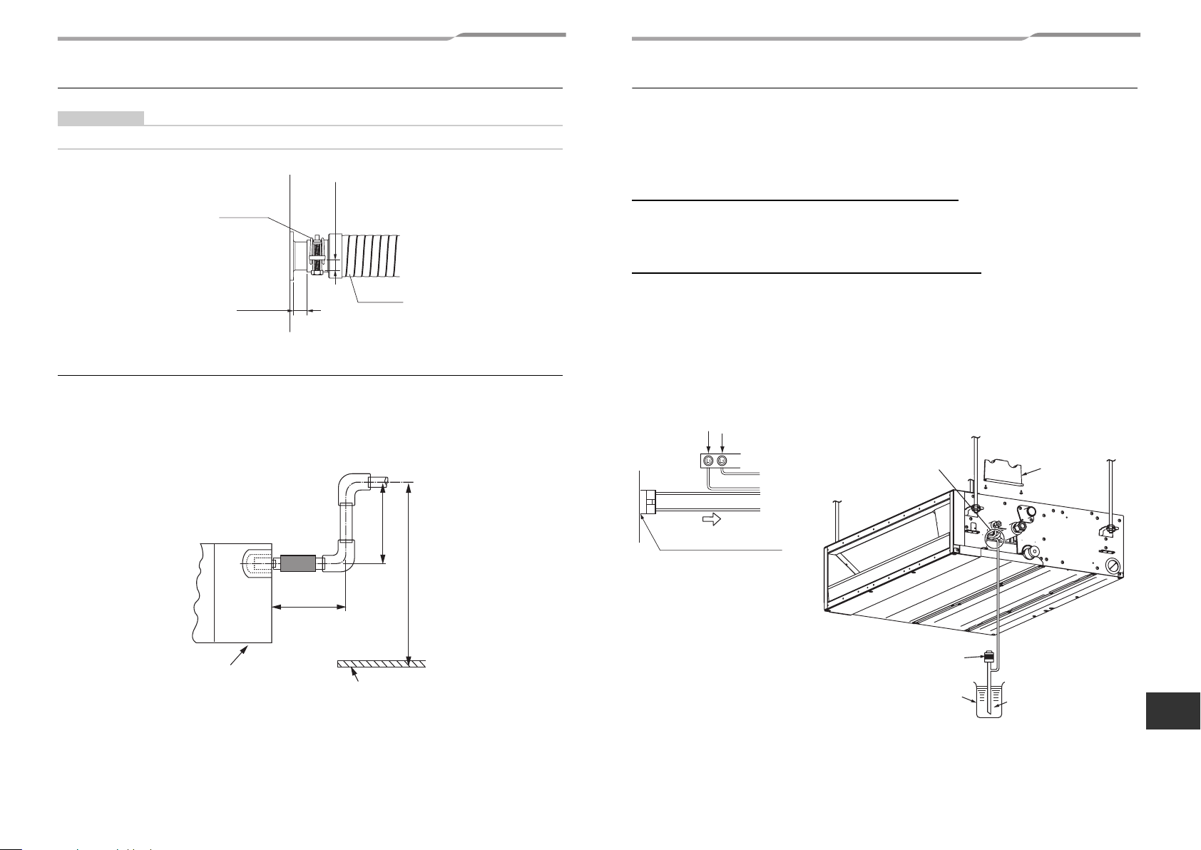
Preparation before installation
CAUTION
The air intake port flange is attached upside down for product protection during shipping. Be sure to reattach the flange
in the correct orientation in order to connect to the duct.
During shipping To install (correct orientation)
Flange Flange
Indoor unit Indoor unit
Screw (10 pieces)
5-EN 6-EN
Page 5
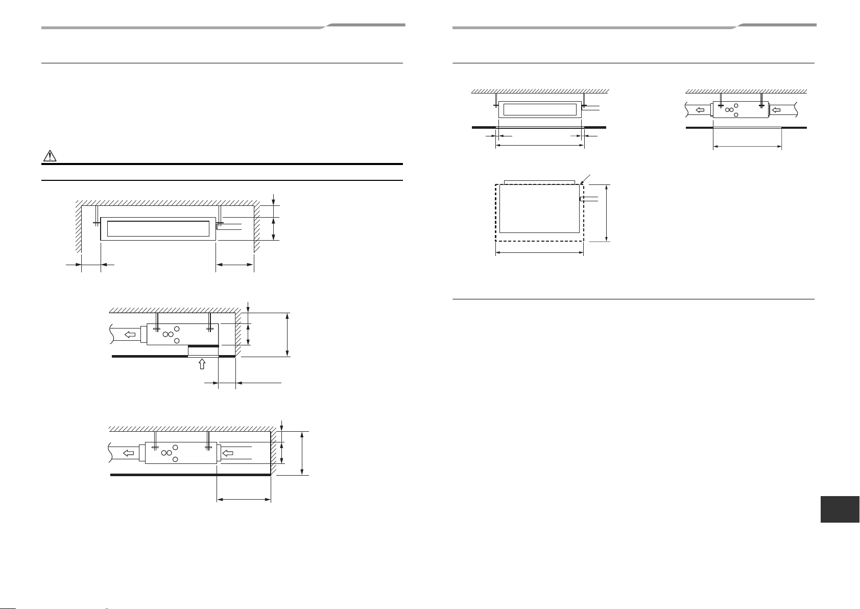
Installation space Unit: in (mm)
Reserve sufficient space required for installation or service work.
The indoor unit does not have a built-in air filter.
The type of air filters required will be specified by applicable codes and requirements for the indoor unit installation.
All filters are locally procured.
Always install the air filter (Local procure) in a location that permits easy maintenance, such as behind the intake
grille. (If no air filter is installed, dust will collect in the heat exchanger, which may cause the air conditioner to fail
or to leak.)
CAUTION
Leave sufficient space to remove the air filter when you attach it.
Service space Unit: in (mm)
Reserve sufficient space required for installation or service work.
Air discharge
Ceiling
2” (50)
39.2” (995)
3.9” (100)
29.3” (745)
Ceiling opening size
<Under air intake>
<Back air intake>
Air discharge
3.9” (100) or more
Ceiling
Ceiling
Air intake
15.8” (400) or
more
0.2” (5) or
more
8.3” (
3.9” (100) or more
Air intake
11.8” (300) or more
0.2” (5) or more
8.3” (
210)
210)
11.2” (285) or more
0.2” (5) or more
8.3”
9.3” (235) or
(
210)
more
29.3” (745)
39.2” (995)
Filter cleaning sign term setting
The lighting term setup of the filter sign (Notification of filter cleaning) of the remote control can be changed
according to the condition of installation.
For setup method, refer to “Filter sign setting” in the Applicable controls of this Manual.
EN
7-EN 8-EN
–4–
Page 6
4 Installation
–5–
WARNING
• Install the air conditioner certainly at a place to sufficiently withstand the weight.
• If the strength is insufficient, the unit may fall down resulting in human injury.
• Perform a specified installation work to guard against an earthquake.
• An incomplete installation can cause accidents by the units falling and dropping.
• Do not install the indoor unit in the way that it takes in the air in the ceiling and provides it into the room. The indoor
unit must be installed in the way that it takes in the air from the room and returns it back to the room.
GOOD NO GOOD NO GOOD
CAUTION
Strictly comply with the following rules to prevent damage of the indoor units and human injury.
• Do not put a heavy article on the indoor unit or let a person get on it. (Even units are packaged)
• Carry in the indoor unit as it is packaged if possible. If carrying in the indoor unit unpacked by necessity, use buffering
cloth or other material to not damage the unit.
• To move the indoor unit, hold the hooking brackets (4 positions) only.
Do not apply force to the other parts (refrigerant pipe, drain pan, foamed parts, resin parts or other parts).
• Carry the package by two or more persons, and do not bundle it with plastic band at positions other than specified.
• To install vibration isolation material to hanging bolts, confirm that it does not increase the unit vibration.
1 room
• This unit and it’s ducting (supply and return air) are intended for use in one room only.
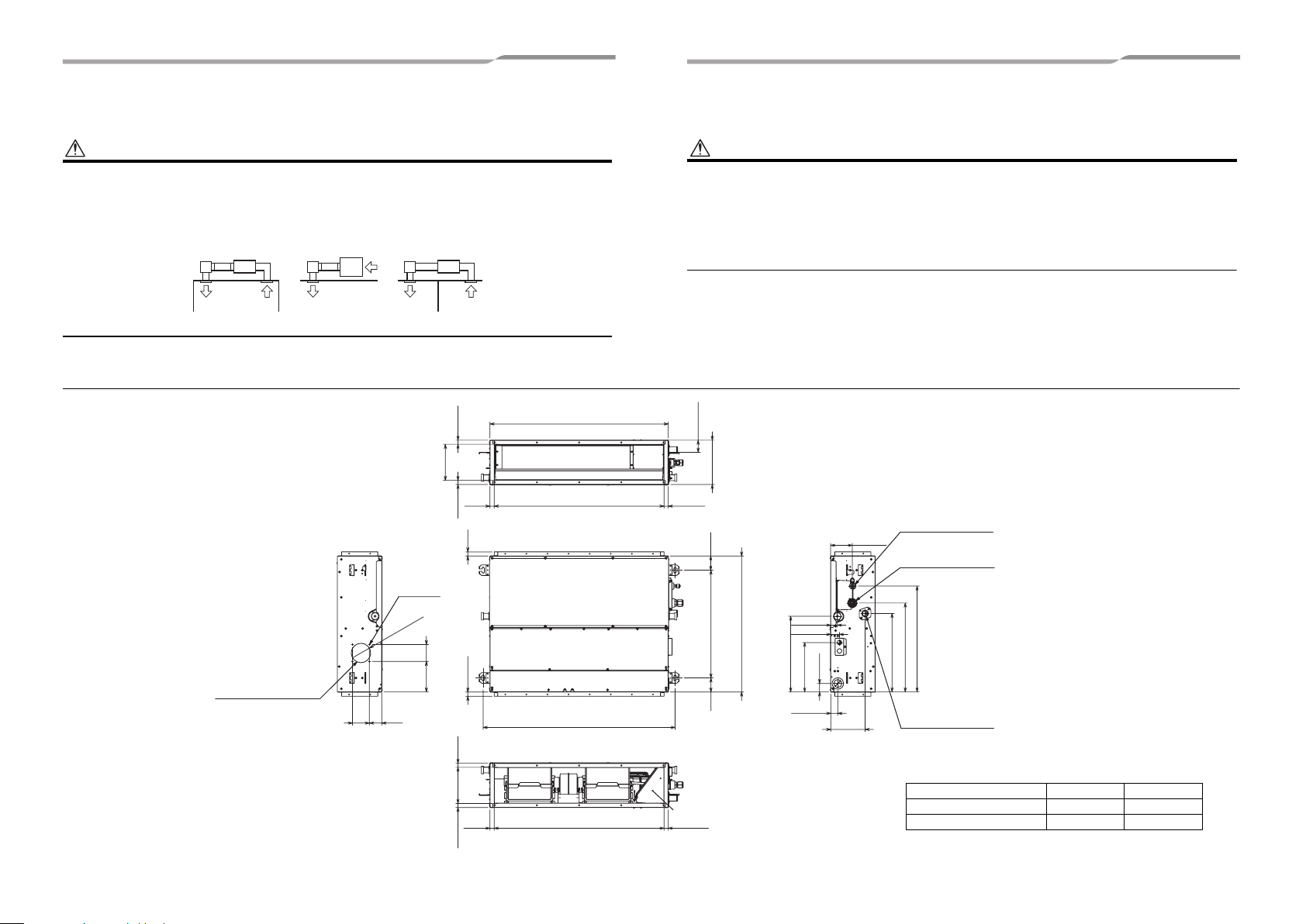
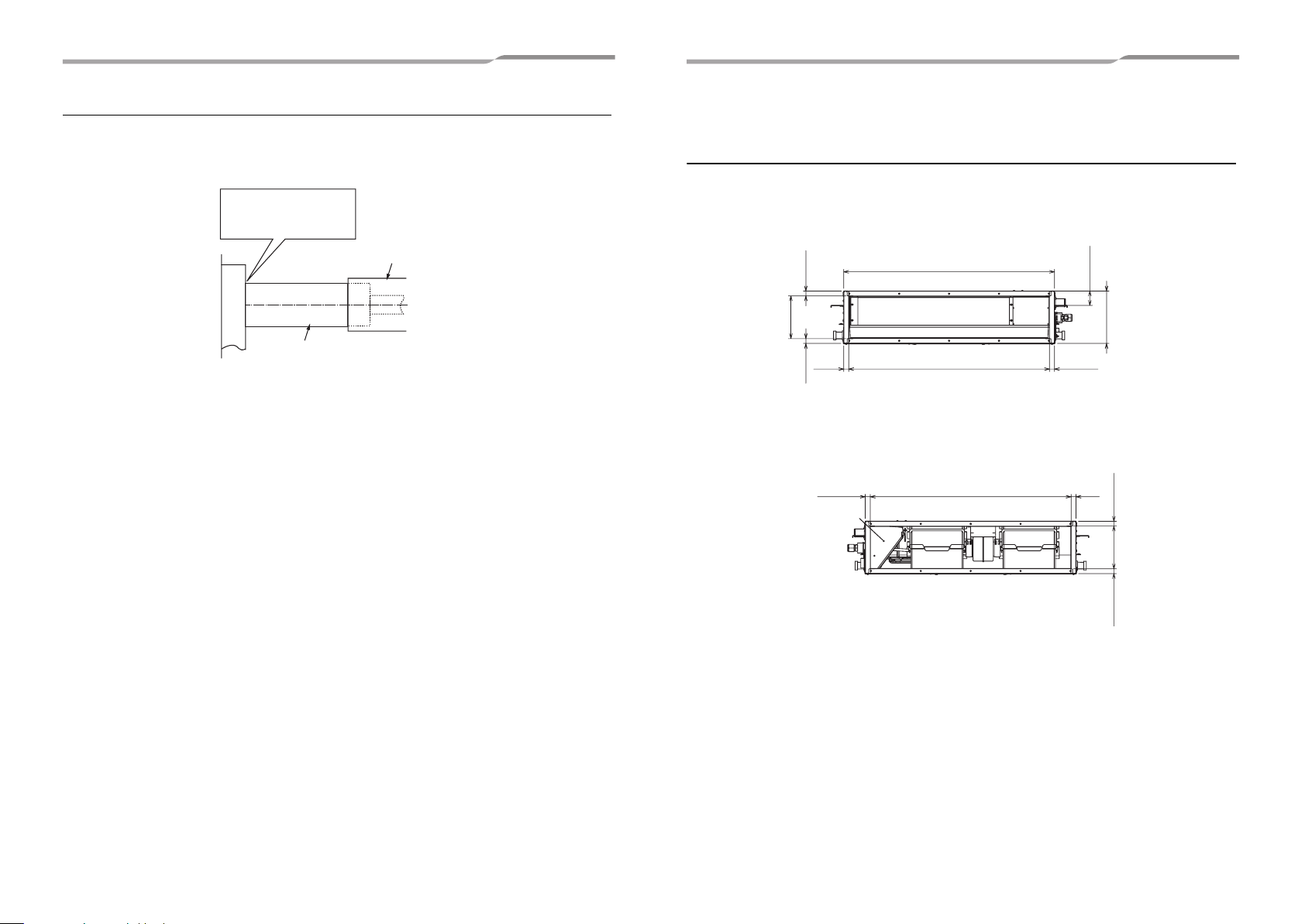
External dimensions Unit: in (mm)
Fresh air intake
(knock-out hole)
3.1”
(80)
3.3”
(59)
3
∅
4-∅0.2”(4)
)
2
9
(
”
6
.
3.1”
(80)
5.7”
(145)
(outside)
6.8”(171.4)
0.8”
0.8”(19.3)
(19.30)
0.8”(20)
0.8”(20)
0.8”
(20)
Unit external dimension 33.3”(845)
Air discharge flange outside
31.7”(805)
Hanging bolt pitch 35.8”(910)
0.8”(20)
2.2”(57)
2.6”
Hanging bolt pitch
2.6”
8.3”(210)
(67)
20.1”(511)
(67)
Refrigerant pipe
connecting port ∅B
4.1”(103)
1.2”(31)
14.1”(359)
1.6”(41)
9.2”(234)
1.3”(33)
1.6”(40)
6.4”(163)
25.4”(645)
Unit external dimention
(Liquid side)
Refrigerant pipe connecting
port ∅A
(Gas side)
19.8”(502)
14.6”(372)
16.6”(422)
Drain-up port
0.8”
(19.3)
6.8”
0.8”
(171.4)
0.8”
(20)
(19.3)
Air intake flange outside
31.7”(805)
Electrical control box
0.8”(20)
Model MMD- A B
AP007, AP009, AP012 3/8” (9.5) 1/4” (6.4)
AP015, AP018 1/2” (12.7) 1/4” (6.4)
9-EN 10-EN
Page 7
Installation of the indoor unit
All issues related to locating the unit above the ceiling,
hanging the unit from the building structure, routing/
suspending the unit refrigerant piping, routing/
suspending the unit wiring and penetrating the ceiling
for supply and return air connections to the indoor unit
must comply with all applicable codes and regulations.
The indoor unit should be hung above
the ceiling utilizing minimum 3/8" x 16
bolts, or threaded rod (4 pieces required) along with 3/
8" x 16 nuts, 3/8" flat washers and 3/8" lock washers.
All material locally procured.
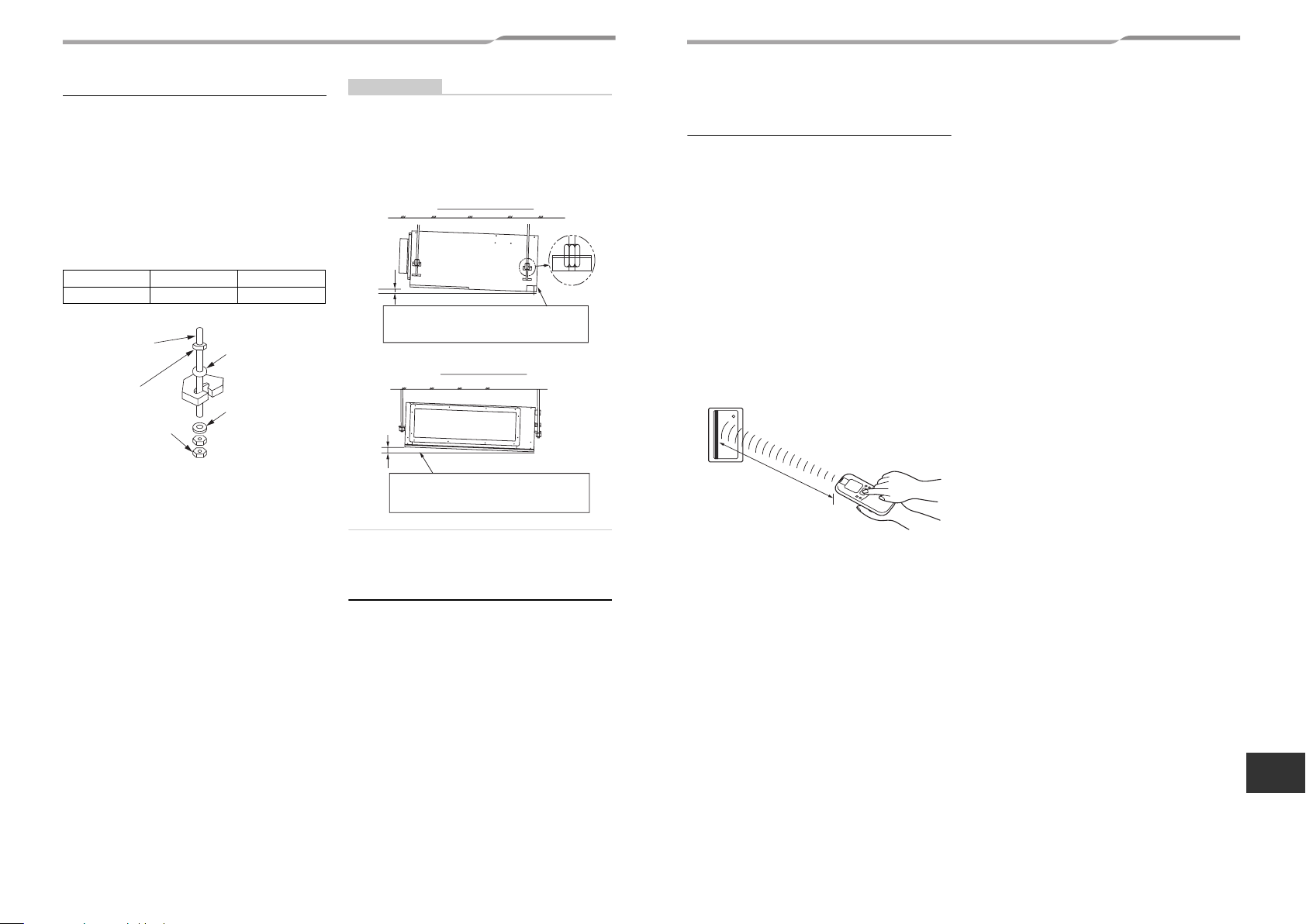
Hanging bolt W3/8” (M10) 4 pieces
Nut W3/8” (M10) 12 pieces
Hanging bolt
(W3/8” (M10))
Nut
(W3/8” (M10))
Nut
(W3/8” (M10))
The unit should be positioned level and plumb without
pitch in any direction. The bolts, or threaded rod should
be attached to the building structure in compliance with
all applicable codes and regulations. The spacing for
the support bolts, or rods should match the dimensions
provided on the unit External dimensions in this
manual.
• Check that four sides are horizontal with a level
gauge. (Horizontal degree: Within 0.2” (5 mm))
M10 flat washer
(Accessory)
M10 flat washer
(Accessory)
REQUIREMENT
• Hang the unit in a horizontal position.
When unit is hanged to slant, it may cause overflow of
drainage.
• Install the unit within the dimension according to the
figure below.
• Use level gauge to confirm whether the unit is hang
horizontally.
Side view
0.2” (5 mm)
or less
Set the drain pipe connecting port side within
0.2” (5 mm) lower than opposite side.
Front view
0.2” (5 mm) or
less
Set the air intake and air discharge sides are
within 0.2” (5 mm) with each other.
Installation of wired remote
control (sold separately)
For installation of the wired remote control refer to the
instructions that are supplied with the control. The
connection point for the control wiring and the entrance
point for the control wiring are clearly marked in the
instructions.
Installation of wireless
remote control
(sold separately)
For installation of the wireless remote control refer to
the instructions that are supplied with the control. The
connection point for the control wiring and the entrance
point for the control wiring are clearly marked in the
instructions.
The sensor of indoor unit with wireless remote control
can receive a signal by distance within approx. 26.2’ (8
m).
Based upon it, determine a place where the remote
control is operated and the installation place.
• Keep 3.3’ (1 m) or more from the devices such as
television, stereo.
(Disturbance of image or noise may generate.)
• To prevent a malfunction, select a place where is not
influenced by a fluorescent light or direct sunlight.
• Two or more (Up to 6 units) indoor units with wireless
type remote control can be installed in the same
room.
2
6
.
2
’
(
8
m
)
o
r
l
e
s
s
EN
11-EN 12-EN
–6–
Page 8
5 Drain piping
–7–
CAUTION
Condensate drain piping installation and material must comply with applicable codes and regulations for the
specific indoor installation.
The condensate drain piping must be insulated to prevent sweating. All material used in the plenum space above
the ceiling must comply with applicable codes and regulations. If the condensate drain exits the unit downward
(gravity flow) the slope and suspension methods used for the condensate drain piping must comply with applicable
codes and regulations.
• The drain pipe must be sloping downward (at an angle of 1/100 or more), and do not run the pipe up and down
(arched shape) or allow it to form traps. Doing so may cause abnormal sounds.
• Restrict the length of the traversing drain pipe to 65.6’ (20 m) or less. For a long pipe, provide support brackets
at intervals of 4’11” to 6’7” (1.5 to 2 m) to prevent flapping.
• Install the collective piping as shown in the following figure.
• Do not provide any air vents. Otherwise, the drain water will spout, causing water to leak.
• Do not allow any force to be applied to the connection area with the drain pipe.
Heat
insulator
4’11” to 6’7”
(1.5 to 2 m)
Downward slope
1/100 or more
Support
bracket
(Collective
piping)
As long as possible
(Approx. 3.9” (100 mm))
Downward slope
1/100 or more
VP30
Arched shape
Trap
Incorrect
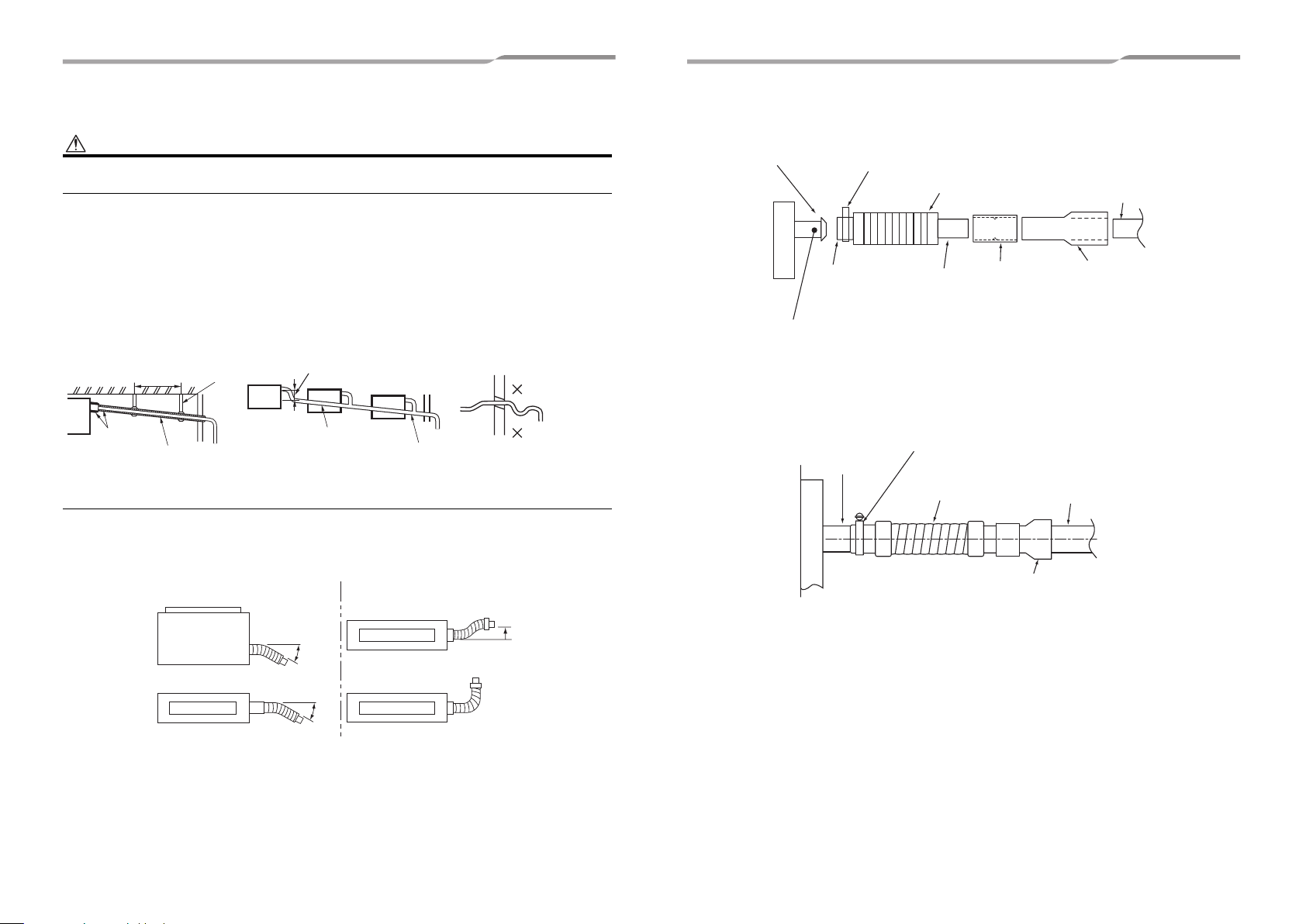
Flexible hose
Use the attached flexible hose to adjust centre discrepancy of the hard vinyl chloride pipe or to adjust the angle.
• Do not use the flexible hose as stretched, or do not deform it more extent than that in the following figure.
• Fix the soft end of the flexible hose with the attached hose band.
• Use the flexible hose on a horizontal level.
OK
Top view
Side view
Air discharge
max
45°
max
45°
NO GOOD
Side view
Air discharge
Side view
Air discharge
Riser (Trap)
90° Bend
Condensate drain connection
for ducted indoor unit, metric
size (not suitable for US size)
PVC stub.
Indoor unit
Adhesive inhibited:
Use the attached flexible hose and hose band for connecting the
drain hose to the clear drain socket.
If applying the adhesive, socket will be damaged and cause water
leakage.
Attached hose
band
Soft socket
Drain pipe
connecting port
(Transparent)
Indoor unit
Attached flexible
hose
Hard socket
Align the attached hose band to
the end of hose, set the
tightening position upward, and
then tighten it.
Flexible hose
(Accessory)
Standard 1" PVC drain pipe installed
by field. Can also be converted at the
adapter to any other size/material
that may be required to comply with
applicable codes, or regulations.
Attached drain
socket
Standard 1" PVC drain pipe installed by
field. Can also be converted at the
adapter to any other size/material that
may be required to comply with
applicable codes, or regulations.
Condensate drain connection
for ducted indoor unit, metric
size (not suitable for US size)
PVC stub.
Condensate drain connection
adapter (provided with indoor
unit). converts metric size unit
drain connection to standard
1" US size PVC connection.
(Hard socket)
13-EN 14-EN
Page 9
Connecting drain pipe
Insert flexible drain hose into upper drain pipe of main unit as far as it will go. Fix it with hose band.
REQUIREMENT
Mount the flexible drain hose using the hose band without using adhesive.
Check the condensate drain system
When all piping and wiring is completed the condensate drain system (including the pump) should be checked for
correct operation and leaks. If there are any abnormal sounds, leaks, or if the condensate water does not flow
normally, the problem should be diagnosed and corrected before the system is certified for operation.
In the test run, check that water drain is properly performed and water does not leak from the connecting part of
the pipes. When doing this, also check that no abnormal sounds are heard from the drain pump motor. Check
draining also when installed in heating period.
Hose band
Indoor unit
0.6” (15 mm) or less
10 to 12 mm)
(
0.4” to 0.5”
Flexible
drain hose
Drain up (condensate pumped up from unit)
When gravity drainage cannot be provided directly from the indoor unit condensate exit the piping can be arranged
for upward condensate discharge. The vertical leg of the drain line must be a maximum of 15.8”(400 mm) or less
from the indoor condensate exit and the total vertical height of the leg must be a maximum of 33.5”(850 mm) or
less before the drain enters a gravity flow line. These dimensions are specified by the indoor unit condensate pump
limitations. As specified for the gravity flow installation all materials and suspension methods must comply with
applicable codes and regulations.
Rising up
23.1”(587 mm)
or less
15.8”(400 mm)
or less
When the electrical and wiring work has been completed
Pour some water by following the method shown in the following figure. Then, while performing a cooling operation,
check that the water drains from the drain pipe connecting port (transparent) and that no water is leaking from the
drain pipe.
When the electrical and wiring work has not been completed
• Disconnect the float switch connector (3P: Red) from the connector (CN34: Red) on the printed circuit board
inside the electrical control box. (Before doing this, the power must be turned off.)
• Connect a 208 / 230 V supply voltage to (L1) and (L2) on the power supply terminal block. (Do not apply a 208
/ 230 V voltage to (A), (B) of the terminal block. Otherwise, the printed circuit board may be damaged.)
• Pour the water by following the method shown in the following figure. (Amount of water poured: 0.4 to 0.5 gal
(1500 to 2000 cc))
• When the power is turned on, the drain pump automatically starts running. Check whether the water is draining
from the drain pipe connecting port, and check that no water is leaking from the drain pipe.
• After checking that the water drains and there are no water leaks, turn off the power, connect the float switch
connector to its original location (CN34) on the printed circuit board, and return the electrical control box to its
original position.
208 / 230-1-60
White
Black
Black
Pull out connector CN34 (Red)
from P.C. board.
Red
Insert the edge of hose into the
drain pan and bend it downward.
Cover plate
Rising up 33.5”(850 mm) or less
Pump
Indoor unit
Underside of ceiling
15-EN 16-EN
–8–
Vessel
Water
(0.4 to 0.5 gal
(1500 to 2000 cc))
EN
Page 10
–9–
Condensate drain pipe insulation
• As shown in the figure, cover the flexible hose and hose band with the attached heat insulator up to the bottom
of the indoor unit tightly.
• Cover the drain pipe tightly with a heat insulator locally procured so that it overlaps with the attached heat
insulator.
Wrap the attached heat
insulator tightly from the
surface of the indoor unit.
Heat insulator
(locally procured)
Indoor unit
Heat insulator of the drain
connecting section
(Accessory)
6 Duct design
Arrangement Unit: in (mm)
Referring to the following dimensions, manufacture duct at the local site.
<Air discharge>
Unit external dimension 33.3”(845)
0.8”(20)
0.8”
(20)
2.2”(57)
8.3”(210)
0.8”(19.3)
<Back air intake>
0.8”(19.3)
outside
6.8”(171.4)
0.8”
(20)
0.8”
(19.30)
0.8”(20)
Electrical control box
Air discharge flange outside
31.7”(805)
31.7”(805)
6.8”(171.4)
0.8”(19.3)
17-EN 18-EN
Page 11
<Under air intake>
31.7”(805)
0.3”(8.2) or less
1.6”(41.5)
3.9”(100)
10.5”(266)
0.5”(12.5)
3.9”(100)
3.9”(100)
3.9”(100)
3.9”(100)
32.5”(825)
3.9”(100)
3.9”(100)
3.9”(100)
3.9”(100)
0.5”(12.5)
11.3”(286.8)
3.9”(100)
1.8”(45.3)
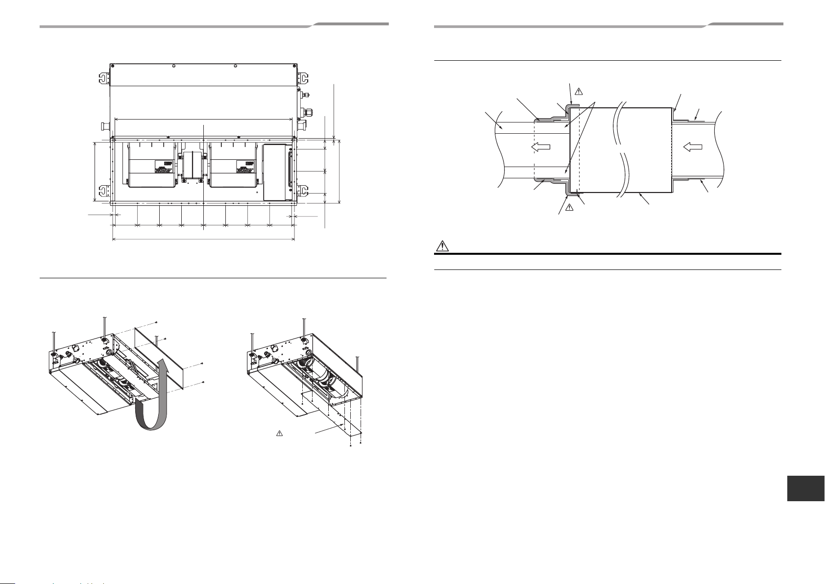
Alteration from the back air intake to the underside air intake
Remove the cover plate from underside. Attach the cover plate to back air intake side.
The intake flange provided (for air intake from the back) cannot be used for air intake from the underside.
Connecting method of the duct
Heat insulator with sticking material (locally procured)
Aluminum tape (locally procured)
Duct: Insulation
materia
(locally procured)
Aluminum tape
(locally procured)
Heat insulator with sticking material (locally procured)
Flange
Air discharge side
Connect a duct to the
inside of the flange
Indoor unit
Cover a screw
CAUTION
Incomplete heat insulation of the supply air flange and sealing may occur dewing resulted in falling of water drop.
Flange
Aluminum tape (locally procured)
Air intake side
Aluminum tape (locally procured)
Under surface
Remove the cover plate and then fix
it to the air intake side
CAUTION
Take out this cover
plate.
EN
19-EN 20-EN
–10–
Page 12
–11–
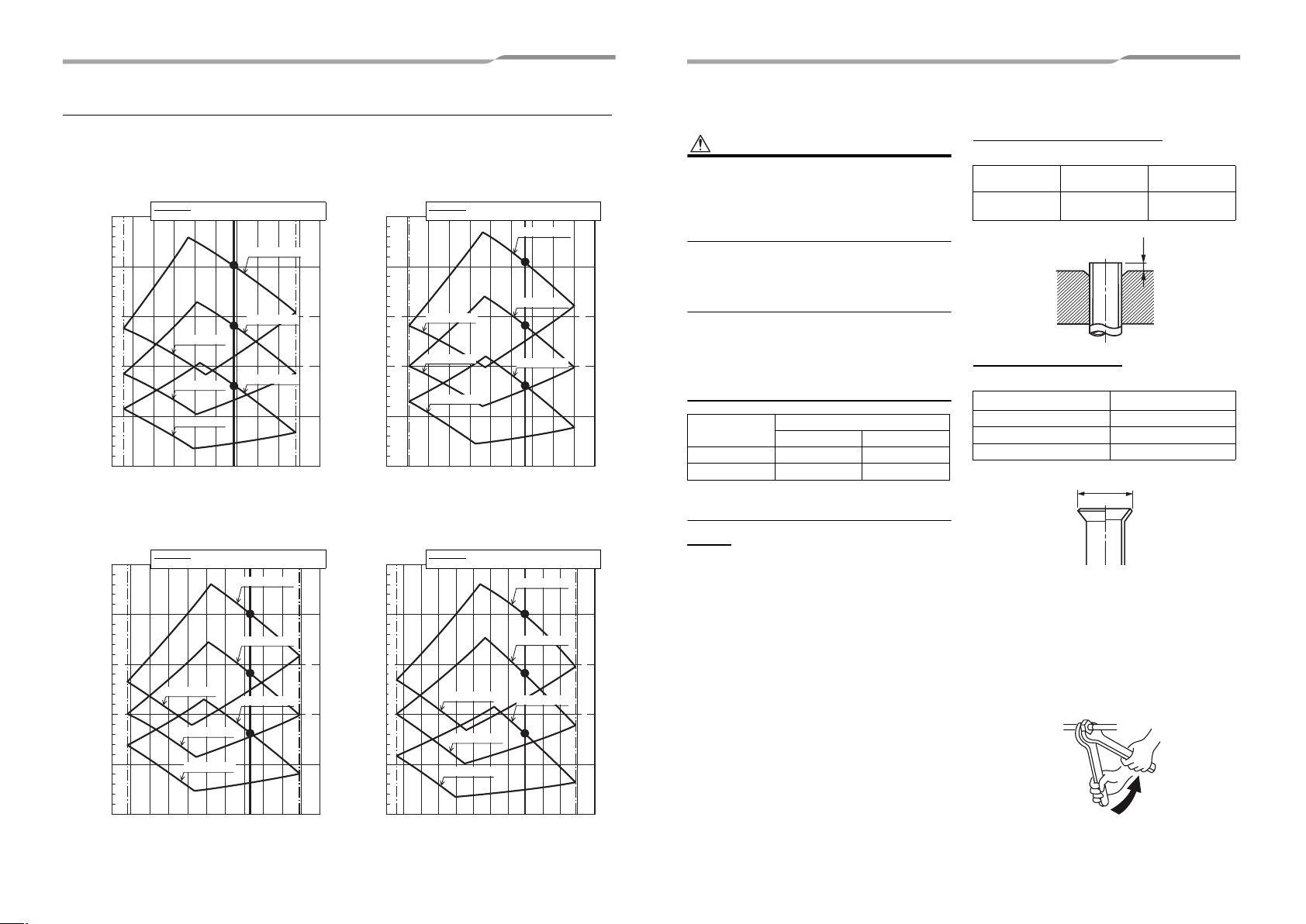
Fan characteristics
◆ No filter
AP007, AP009 AP012
Standerd air flow rate: 317.8 (cfm)
Dotted line: Upper limit of external static pressure
0.250
0.200
0.150
0.100
Air flow rate lower limit
External static pressure (in.WG)
0.050
0.000
200 220 240 260 280 300 320 340 360 380 400
AP015 AP018
0.250
0.200
0.150
0.100
Air flow rate lower limit
External static pressure (in.WG)
0.050
Lower limit of external static pressure
High (0.20 in.WG)
High (0.14 in.WG)
Low (0.20 in.WG)
Low (0.14 in.WG)
Low (0.80 in.WG)
Air flow rate (cfm)
Standerd air flow rate: 406.1 (cfm)
Dotted line: Upper limit of external static pressure
Lower limit of external static pressure
Low (0.20 in.WG)
Low (0.14 in.WG)
Low (0.80 in.WG)
High (0.08 in.WG)
High (0.20 in.WG)
High (0.14 in.WG)
High (0.08 in.WG)
Air flow rate upper limit
External static pressure (in.WG)
Air flow rate upper limit
External static pressure (in.WG)
Standerd air flow rate: 353.1 (cfm)
Dotted line: Upper limit of external static pressure
0.250
0.200
0.150
0.100
Air flow rate lower limit
0.050
0.000
220 240 260 280 300 320 340 360 380 420400
0.250
0.200
0.150
0.100
Air flow rate lower limit
0.050
Lower limit of external static pressure
High (0.20 in.WG)
Low (0.20 in.WG)
Low (0.14 in.WG)
Low (0.80 in.WG)
Air flow rate (cfm)
Standerd air flow rate: 459.0 (cfm)
Dotted line: Upper limit of external static pressure
Low (0.20 in.WG)
Low (0.14 in.WG)
Low (0.80 in.WG)
High (0.14 in.WG)
High (0.08 in.WG)
Lower limit of external static pressure
High (0.20 in.WG)
High (0.14 in.WG)
High (0.08 in.WG)
7 Refrigerant piping
CAUTION
When the refrigerant pipe is long, provide support
brackets at intervals of 8’2” to 9’10” (2.5 to 3 m) to clamp
the refrigerant pipe. Otherwise, abnormal sound may be
generated.
Use the flare nut attached with the indoor unit or R410A
flare nut.
Permissible piping length and
height difference
They vary depending on the outdoor unit. For details,
refer to the Installation Manual attached to the outdoor
unit.
Air flow rate upper limit
Pipe size Unit: in (mm)
Model MMD-
AP007 to AP012 3/8” (9.5) 1/4” (6.4)
AP015 to AP018 1/2” (12.7) 1/4” (6.4)
Pipe size
Gas side Liquid side
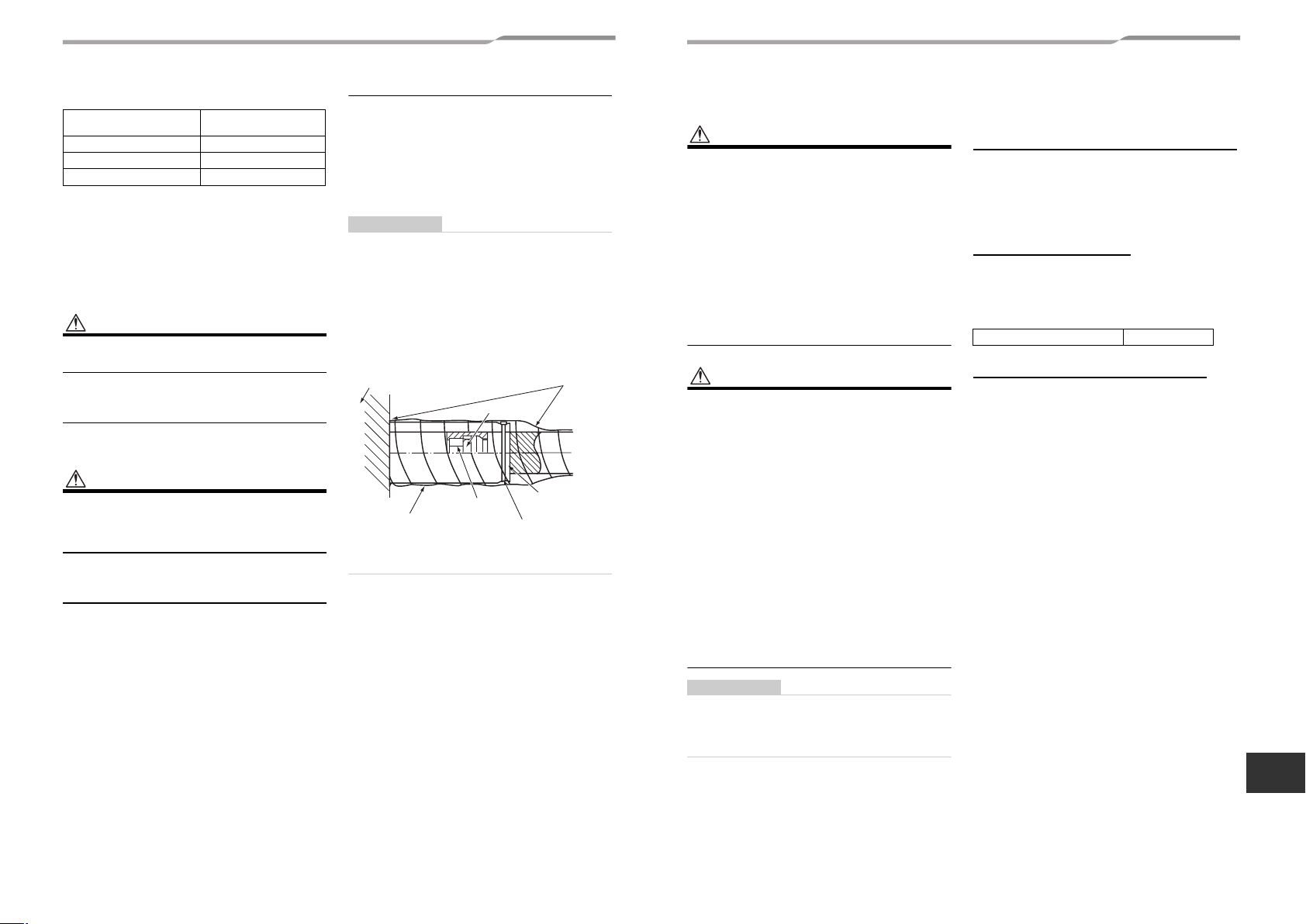
Connecting refrigerant piping
Flaring
1 Cut the pipe with a pipe cutter.
Remove burrs completely. (Remaining burrs may
cause gas leakage.)
2 Insert a flare nut into the pipe, and flare the
pipe.
Use the flare nut provided with the unit or the one
used for the R410A refrigerant. The flaring
dimensions for R410A are different from the ones
used for the conventional R22 refrigerant. A new
flare tool manufactured for use with the R410A
refrigerant is recommended, but the conventional
Air flow rate upper limit
tool can still be used if the projection margin of the
copper pipe is adjusted to be as shown in the
following table.
Projection margin in flaring: B
Unit: in (mm)
Outer dia. of
copper pipe
1/4” to 1/2”
(6.4 to 12.7)
R410A tool used
0 to 0.02”
(0 to 0.5)
Conventional
tool used
0.04” to 0.06”
(1.0 to 1.5)
B
Flaring diameter size: A
Unit: in (mm)
Outer dia. of copper pipe A
1/4” (6.4) 0.36” (9.1)
3/8” (9.5) 0.52” (13.2)
1/2” (12.7) 0.65” (16.6)
A
* In case of flaring for R410A with the conventional
flare tool, pull it out approx. 0.02” (0.5 mm) more than
that for R22 to adjust to the specified flare size. The
copper pipe gauge is useful for adjusting projection
margin size.
• The sealed gas was sealed at the atmospheric
pressure so when the flare nut is removed, there will
no “whooshing” sound: This is normal and is not
indicative of trouble.
• Use two wrenches to connect the indoor unit pipe.
+0
–0.02” (0.4)
0.000
260 280 300 320 340 360 380 480400 420 440 460
Air flow rate (cfm)
0.000
300 480 500 520320 340 360 380 540400 420 440 460
Air flow rate (cfm)
Work using double spanner
21-EN 22-EN
Page 13
• Use the tightening torque levels as listed in the
following table.
Outer dia. of connecting
pipe (in (mm))
1/4” (6.4) 10 to 13 (14 to 18)
3/8” (9.5) 24 to 31 (33 to 42)
1/2” (12.7) 37 to 46 (50 to 62)
• Tightening torque of flare pipe connections.
Pressure of R410A is higher than that of R22.
(Approx. 1.6 times) Therefore, using a torque
wrench, tighten the flare pipe connecting sections
which connect the indoor and outdoor units of the
specified tightening torque.
Incorrect connections may cause not only a gas leak,
but also an error of the refrigeration cycle.
Tightening torque
(ft•lbs (N•m))
CAUTION
Tightening with an excessive torque may crack the nut
depending on installation conditions.
Airtight test / air purge, etc.
For air tightness test, adding refrigerant, refer to the
Installation Manual attached to the outdoor unit.
CAUTION
Do not supply power to the indoor unit until the airtight
test and vacuuming are completed. (If the indoor unit is
powered on, the pulse motor valve is fully closed, which
extends the time for vacuuming.)
Open the valve fully
Open the valve of the outdoor unit fully.
Heat insulation process
Apply heat insulation for the pipes separately at liquid
side and gas side.
• For the heat insulation to the pipes at gas side, use
the material with heat-resisting temperature 248 °F
(120 °C) or higher.
• To use the attached heat insulation pipe, apply the
heat insulation to the pipe connecting section of the
indoor unit securely without gap.
REQUIREMENT
• Apply the heat insulation to the pipe connecting
section of the indoor unit securely up to the root
without exposure of the pipe. (The pipe exposed to the
outside causes water leak.)
• Wrap heat insulator with its slits facing up (ceiling
side).
• Apply heat insulating materials to both the gas side
and liquid side as shown:
To cover the pipe and the
indoor unit with a heat
insulator, do not make a
Indoor unit
Wrap the insulator
with adhesive tale.
(locally procured)
gap between them.
Flare nut
Union
Heat insulator
of the pipe
Banding band
(Accessory)
8 Electrical connection
WARNING
1. Use predefined wire and connect them certainly.
Keep the connecting terminal free from external
force.
Improper wire connection or clamping may result in
exothermic, fire or malfunction.
2. Connect ground wire. (grounding work)
Incomplete grounding cause an electric shock.
Do not connect ground wires to gas pipes, water
pipes, lightning rods or ground wires for telephone
wires.
3. Install appliance in accordance with national
wiring regulations.
Capacity shortage of circuit breaker or incomplete
installation may cause an electric shock or a fire.
CAUTION
• Consult local building codes, NEC (National Electrical
Code) or CEC (Canadian Electrical Code) for special
requirements.
• If incorrect / incomplete wiring is carried out, it will
cause an electrical fire or smoke.
• Install circuit breaker is not tripped by shock waves.
If circuit breaker is not installed, an electric shock may
be caused.
• Use the cord clamps attached to the product.
• Do not damage or scratch the conductive core and
inner insulator of power and control wires when
peeling them.
• Use the power cord and control wire of specified
thickness, type, and protective devices required.
• Do not connect 208 / 230 V power to the terminal
blocks (U1, U2, A, B etc.) for control wiring.
(Otherwise, the system will fail.)
• Perform the electric wiring so that it does not come to
contact with the high-temperature part of the pipe.
The coating may melt resulting in an accident.
• Do not turn on the circuit breaker of the indoor unit
until vacuuming of the refrigerant pipes completes.
Power supply wire and
control wires specifications
Power supply wire and control wires are locally
procured.
For the power supply specifications, follow to the table
below. If capacity is little, it is dangerous because
overheat or seizure may be caused.
Indoor unit power supply
For the power supply of the indoor unit, prepare the
exclusive power supply separated from that of the
outdoor unit.
▼ Power supply
Power supply 208 / 230-1-60
Control wiring, Central control wiring
• 2-core with non-polarity wires are used for the
control wiring between indoor unit and outdoor unit
and Central control wiring.
• To prevent noise trouble, use 2-core shielded wire.
• The length of the communication line means the total
length of the control wire length between indoor and
outdoor units added with the central control wire
length.
REQUIREMENT
• For power supply wiring, strictly conform to the Local
Regulation in each country.
• Run the refrigerant piping line and control wir ing line in
the same line.
EN
23-EN 24-EN
–12–
Page 14
–13–
Power supply wire
Recommended wire diameter and wire length for power supply wire.
Power supply wiring
▼ Electric characteristics
Model Power Supply
MMD-AP0074SPH2UL
MMD-AP0094SPH2UL 0.73 15
MMD-AP0124SPH2UL 0.75 15
MMD-AP0154SPH2UL 0.88 15
MMD-AP0184SPH2UL 1.00 15
208 / 230 V-1-60 Hz 187 253
Wire size: 2 × AWG14
Ground 1 × AWG14 or thicker
MOCP : Maximum Overcurrent Protection (Amps)
Up to 164’1” (50 m)
MCA : Minimum Circuit Amps
Voltage Range (V) MCA MOCP
Min Max (A) (A)
0.73 15
Control wire
Control wiring between indoor units, and outdoor unit (2-core
shielded wire)
Wire size
(Up to 3280’10” (1000 m)) AWG16
(Up to 6561’8” (2000 m)) AWG14
Remote control wiring
2-core with non-polarity wire is used for wiring of the remote control wiring and group remote controls wiring.
Remote control wiring, remote control inter-unit wiring Wire size: AWG20
Total wire length of remote control wiring and remote control
inter-unit wiring = L + L1 + L2 + … Ln
Total wire length of remote control inter-unit wiring = L1 + L2 + … Ln Up to 656’2” (200 m)
Remote
control
wiring
Indoor unit
L
Remote
control
Indoor unit Indoor unit Indoor unit
L1
Remote control inter-unit wiring
NOTE
• Use copper supply wire.
• Use UL wire rated 600 V for the power supply.
• Use UL wire rated 300 V for the remote control wires and control wires.
In case of wired type only Up to 1640’5” (500 m)
In case of wireless type included Up to 1312’4” (400 m)
L2 Ln
(Max. 8 units)
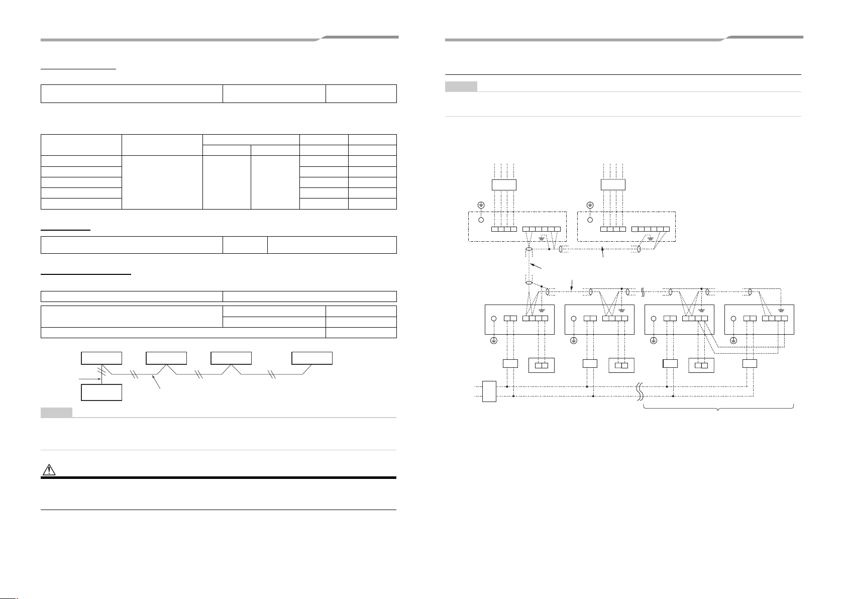
Wiring between indoor and outdoor units
NOTE
An outdoor unit connected with control wiring between indoor and outdoor units wire becomes automatically the header
unit.
▼ Wiring example
Disconnect
switch per NEC
Indoor
power
supply
208 /
230-1-60
Outdoor Power supply
Circuit breaker Circuit breaker
Header outdoor unit
Ground
terminal
Indoor unit
Ground Ground Ground Ground
Circuit
breaker
U1U2U3U4L1 L2L3 N U5U6
Control wiring between indoor and outdoor units
Control wiring between indoor units
U1U2
L1L2 A BU1U2L1L2 A B U1U2L1L2 A B U1U2L1L2 A B
A B
Remote
control
Outdoor Power supply
Follower outdoor unit
Ground
terminal
Control wiring between outdoor units
Indoor unit Indoor unit
Disconnect
switch per
NEC
U1U2U3U4L1 L2L3 N U5U6
Disconnect
A B A B
switch per
NEC
Remote
control
Remote
control
Group control
Indoor unit
Disconnect
switch per
NEC
CAUTION
The remote control wire (Communication line) and AC208 / 230 V wires cannot be parallel to contact each other and
cannot be stored in the same conduits. If doing so, a trouble may be caused on the control system due to noise or other
factor.
25-EN 26-EN
Page 15

Wire connection
REQUIREMENT
• Connect the wires matching the terminal numbers.
Incorrect connection causes a trouble.
• Pass the wires through the bushing of wire connection
holes of the indoor unit.
• The low-voltage circuit is provided for the remote
control. (Do not connect the high-voltage circuit)
• Remove the underside cover plates (2 plates).
Remove the two screws from the electrical control
box cover and then remove the cover from the hook
on which it is hanging.
• Remove the conduit plate from the side plate and
attach the conduit to the conduit plate.
Next, attach the conduit plate to the side plate.
• Tighten the screws of the terminal block, and fix the
wires with cord clamp attached to the electrical
control box.
(Do not apply tension to the connecting section of the
terminal block.)
• Mount the cover of the electrical control box without
pinching wires.
Conduit plate
Electrical control box
Power supply wire
and ground wire
Cord
clamp
Ground
screw
Electrical control box cover
fixed screw
Hook
Remote
control wire
Electrical control box
cover
Cord clamp
Control
wire (2core
shielded
wire)
Power supply wires and
ground wire
1 Strip the wire ends.
Power supply wire: 0.4” (10 mm)
Ground wire: 0.8” (20 mm)
2 Match the wire colors with the terminal
numbers on the indoor units’ and circuit
breakers’ terminal blocks and firmly screw
the wires to the corresponding terminals.
3 Secure the ground wire with the ground
screw.
4 Fix the wires with a cord clamp.
Unit: in (mm)
0.8” (20)
L1 L2
Ground wire
1.2” (30)
0.4” (10)
Address setup
Set up the addresses as per the Installation Manual
supplied with the outdoor unit.
LL
B A
CAUTION
Firmly tighten the screws of the terminal block.
Keep the wire length as shown in figure below when it
is connected to the terminal block.
Remove
cover plate
0.08” (2) or less
Power supply wires and control
wire
Bushing of control
Conduit
27-EN 28-EN
Conduit
plate
and remote
control wires
–14–
EN
Page 16

–15–
9 Applicable controls
REQUIREMENT
When the air conditioner is used for the first time, it will
take some moments after the power has been turned on
before the remote control becomes available for
operations: This is normal and is not indicative of trouble.
• Concerning the automatic addresses (The automatic
addresses are set up by performing operations on the
outdoor interface circuit board.)
While the automatic addresses are being set up, no
remote control operations can be performed. Setup
takes up to 10 minutes (usually about 5 minutes).
• When the power is turned on after automatic address
setup
It takes up to 10 minutes (usually about 3 minutes) for
the outdoor unit to start operating after the power has
been turned on.
Before the air conditioner was shipped from the factory,
all units are set to [STANDARD] (factory default). If
necessary, change the indoor unit settings.
The settings are changed by operating the wired remote
control.
* The settings cannot be changed using only a
wireless remote control, simple remote control or
group control remote control by itself so install a
wired remote control separately as well.
Basic procedure for changing
settings
Change the settings while the air conditioner is not
working. (Stop the air conditioner before making
settings.)
CAUTION
Set only the CODE No. shown in the following table: Do
NOT set any other CODE No.
If a CODE No. not listed is set, it may not be possible to
operate the air conditioner or other trouble with the
product may result.
1
3
4
6
5
1
2
1 Push and hold button and “TEMP.”
button simultaneously for at least 4
seconds. After a while, the display flashes
as shown in the figure. Confirm that the
CODE No. is [01].
If the CODE No. is not [01], push button to clear
the display content, and repeat the procedure from
the beginning. (No operation of the remote control
is accepted for a while after button is pushed.)
(While air conditioners are operated under the
group control, “ALL” is displayed first. When
is pushed, the indoor unit number
displayed following “ALL” is the header unit.)
2 Each time button is pushed, indoor
unit numbers in the control group change
cyclically. Select the indoor unit to change
settings for.
The fan of the selected unit runs and the
louvers start swinging. The indoor unit for
change settings can be confirmed.
3 Specify CODE No. [ ] with “TEMP.” /
buttons.
4 Select SET DATA [ ] with “TIME” /
buttons.
5 Push button. When the display changes
from flashing to lit, the setup is completed.
• To change settings of another indoor unit,
repeat from Procedure
• To change other settings of the selected indoor
unit, repeat from Procedure
Use button to clear the settings. To make
settings after button was pushed, repeat from
Procedure
2.
2.
3.
6 When settings have been completed, push
button to determine the settings.
When button is pushed, flashes and
then the display content disappears and the air
conditioner enters the normal stop mode.
(While is flashing, no operation of the
remote control is accepted.)
(* Display content varies with the indoor unit
model.)
29-EN 30-EN
Page 17

External static pressure settings
Set up a tap change based upon the external static pressure of the duct to be connected.
To set up a tap change, follow to the basic operation procedure (
• Specify [5d] to the CODE No. in procedure
• For the SET DATA of procedure
following table.
<Change on wired remote controller>
SET DATA External static pressure
0001 0.003 psi (20 Pa) Standard (Factory default)
0003 0.005 psi (35 Pa) High static pressure 2
0006 0.007 psi (50 Pa) High static pressure 3
With a remote controller-less system (group control)
Besides the switching method using the wired remote controller as a way to establish the external static pressure
switching is also possible by changing over the jumper block settings on the indoor P.C. board as shown in the
following table.
* However, once these settings are changed, it is necessary to reset the SET DATA to 0001 that placing the
jumper block back to the factory default position and rewriting the SET DATA back to 0001 with wired remote
controller (sold separately).
• Change over the jumper blocks on the indoor P.C. board, and select the desired setting.
Jumper block positions (CN112, CN111 and CN110 from the left)
Jumper block position
Short
Open
SET DATA 0001 0003 0006
External static pressure
4, select a SET DATA of the external static pressure to be set up from the
CN112 CN111 CN110
0.003 psi (20 Pa) 0.005 psi (35 Pa) 0.007 psi (50 Pa)
(Factory default)
3.
Standard
1 → 2 → 3 → 4 → 5 → 6).
CN112 CN111 CN110
High static Pressure 2 High static Pressure 3
CN112 CN111 CN110
Filter sign setting
According to the installation condition, the filter sign
term (Notification of filter cleaning) can be changed.
Follow to the basic operation procedure
1 → 2 → 3 → 4 → 5 → 6).
(
• For the CODE No. in Procedure
• For the [SET DATA] in Procedure
DATA of filter sign term from the following table.
SET DATA Filter sign term
0000 None
0001 150 H
0002
0003 5000 H
0004 10000 H
3, specify [01].
4, select the SET
2500 H
(Factory default)
To secure better effect of
heating
When it is difficult to obtain satisfactory heating due to
installation place of the indoor unit or structure of the
room, the detection temperature of heating can be
raised. Also use a circulator or other machinery to
circulate heat air near the ceiling.
Follow to the basic operation procedure
1 → 2 → 3 → 4 → 5 → 6).
(
• For the CODE No. in Procedure
• For the set data in Procedure
DATA of shift value of detection temperature to be
set up from the following table.
SET DATA Detection temperature shift value
0000 No shift
0001 1.8 °F (+1 °C)
0002
0003 5.4 °F (+3 °C)
0004 7.2 °F (+4 °C)
0005 9.0 °F (+5 °C)
0006 10.8 °F (+6 °C)
3, specify [06].
4, select the SET
3.6 °F (+2 °C)
(Factory default)
Remote control sensor
The temperature sensor of the indoor unit senses room
temperature usually. Set the remote control sensor to
sense the temperature around the remote control.
Select items following the basic operation procedure
1 → 2 → 3 → 4 → 5 → 6).
(
• Specify [32] for the CODE No. in Procedure
• Select the following data for the SET DATA in
Procedure
SET DATA 0000 0001
remote control
sensor
When flashes, the remote control sensor is
defective.
Select the SET DATA [0000] (not used) or replace the
remote control.
4.
(Factory default)
Not used
3.
Used
Group control
In a group control, a remote control can control up to
maximum 8 units.
• The wired remote control only can control a group
control. The wireless remote control is unavailable
for this control.
• For wiring procedure and wires of the individual line
(Identical refrigerant line) system, refer to “Electrical
connection” in this Manual.
• Wiring between indoor units in a group is performed
in the following procedure.
• Connect the indoor units by connecting the remote
control wires from the remote control terminal blocks
(A, B) of the indoor unit connected with a remote
control to the remote control terminal blocks (A, B) of
the other indoor unit. (Non-polarity)
• For address setup, refer to the Installation Manual
attached to the outdoor unit.
EN
31-EN 32-EN
–16–
Page 18

–17–
10Test run
Before test run
• Before turning on the power supply, carry out the
following procedure.
1) By using 500 V-megger, check that resistance
of 1 MΩ or more exists between the terminal
1 to L2 and the earth (grounding).
block L
If resistance of less than 1 MΩ is detected, do
not run the unit.
2) Check the valve of the outdoor unit being
opened fully.
• To protect the compressor at activation time, leave
power-ON for 12 hours or more before operating.
• Do not press the electromagnetic contactor to
forcibly perform a test run. (This is very dangerous
because the protective device does not work.)
• Before starting a test run, set addresses by following
the Installation Manual supplied with the outdoor
unit.
Execute a test run
Operate the unit with the wired remote control as usual.
For the procedure of the operation, refer to the
attached Owner’s Manual to the outdoor unit.
A forced test run can be executed in the following
procedure even if the operation stops by thermostatOFF.
In order to prevent a serial operation, the forced test
run is released after 60 minutes have passed and
returns to the usual operation.
Wired remote control
2, 4
3
1,5
1 Push button for 4 seconds or more.
[TEST] is displayed on the display part and
the selection of mode in the test mode is
permitted.
2 Push button.
3 Select the operation mode with
button, [ Cool] or [ Heat].
• Do not run the air conditioner in a mode other
than [ Cool] or [ Heat].
• The temperature controlling function does not
work during test run.
• The detection of error is performed as usual.
Wireless remote control
1 Remove a small screw which fixes the
nameplate of the receiver unit.
Remove the nameplate of the sensor section
by inserting a flat-blade screwdriver into the
notch at the bottom of the plate, and set the
Dip switch to [TEST RUN ON].
2 Execute a test operation with ON / OFF
button on the wireless remote control.
• , , and LED flash during test operation.
• Under status of [TEST RUN ON], the
temperature adjustment from the wireless
remote control is invalid.
Do not use this method in the operation other than
test operation because the equipment is
damaged.
3 Use either Cool or Heat operation mode for a
test operation.
• The outdoor unit does not operate approx. 3
minutes after power-ON and operation stop.
4 After the test operation finished, stop the air
conditioner from the wireless remote
control, and return Dip switch of the receiver
section as before.
(A 60-minutes timer clearing function is attached
to the receiver section in order to prevent a
continuous test operation.)
Receiver unit
M4 × 25 screw
(2 pieces)
Spacer
If a test run cannot be
properly performed
If a test run is performed before the outside duct is
installed, the protective control works to stop the unit,
and the check code “P12” appears. This is not a
malfunction.
(The current control works and heating protection
control due to the characteristics of the DC motor
employed as the indoor fan motor of this model.)
If performing a test run before installing the outside
duct, set the air volume to LOW, or block the air vent.
CAUTION
Do not use the forced test run for cases other than the
test run because it applies an excessive load to the
devices.
4 After the test run, push button to
stop a test run.
(Display part is same as procedure 1.)
5 Push button to cancel (release from) the
test run mode.
([TEST] disappears on the display and the status
returns to a normal.)
33-EN 34-EN
Small
screw
Notch
Nameplate
Page 19

11Troubleshooting
Confirmation and check
When an error occurred in the air conditioner, the
check code and the indoor UNIT No. appear on the
display part of the remote control.
The check code is only displayed during the operation.
If the display disappears, operate the air conditioner
according to the following “Confirmation of error log” for
confirmation.
Check code Indoor UNIT No. in
which an error occurred
Confirmation of error log
When an error occurred on the air conditioner, the error
log can be confirmed with the following procedure.
(The error log is stored in memory up to 4 errors.)
The log can be confirmed from both operating status
and stop status.
2
3
1
Procedure 2
Push button. The error log stored in memory is
displayed in order.
The numbers in CODE No. indicate CODE No. [01]
(latest) → [04] (oldest).
REQUIREMENT
Do not push button because all the error log of the
indoor unit will be deleted.
Procedure 3
Push button to return to the usual display after
confirmation.
1. Check the errors according to the above procedure.
2. Ask an authorized dealer or qualified service
(maintenance) professional to repair or maintain the
air conditioner.
Procedure 1
Push and buttons simultaneously for 4 seconds
or more, the following display appears.
If [Service check] is displayed, the mode enters in
the error log mode.
•[01: Order of error log] is displayed in CODE No.
window.
• [Check code] is displayed in CHECK window.
• [Indoor unit address in which an error occurred] is
displayed in Unit No.
EN
35-EN 36-EN
–18–
Page 20

–19–
Check codes and parts to be checked
Check method
On the remote control (Wired remote control, Central control remote control) and the interface P.C. board of the
outdoor unit (I/F), a check display LCD (Remote control) or 7-segment display (on the outdoor interface P.C. board)
to display the operation is provided. Therefore the operation status can be known. With this self-diagnosis function,
a trouble or position with error of the air conditioner can be found as shown in the table below.
Check code list
The following list shows each check code. Find the check contents from the list according to part to be checked.
• To check from indoor remote control: See “Wired remote control display” in the list.
• To check from outdoor unit: See “Outdoor 7-segment display” in the list.
• To check from indoor unit with a wireless remote control: See “Sensor block display of receiving unit” in the list.
Check code Wireless remote control
Wired remote
control display
E01 — —
E02 — — Remote control transmission error Remote control
E03 — —
E04 — —
E06 E06
—E07 —
E08 E08 Duplicated indoor addresses Duplicated indoor addresses Indoor / I/F
E09 — — Duplicated header remote controls Remote control
E10 — — Communication error between indoor MCU Indoor
E12 E12
E15 E15 — Indoor is nothing during automatic addressing I/F
E16 E16
E18 — — Communication error between indoor units Indoor
E19 E19
E20 E20
E23 E23 —
E25 E25 — Duplicated follower outdoor addresses I/F
E26 E26
E28 E28 Detected outdoor unit number Follower outdoor unit error I/F
Outdoor 7-segment display
Auxiliary code
No. of indoor units in which
sensor has been normally
received
01: Indoor / Outdoor
communication
02: Communication between
outdoor units
00: Capacity over
01 ~:No. of connected units
00: Header is nothing
02: Two or more header units
01: Outdoor of other line
connected
02: Indoor of other line connected
No. of outdoor units which
received signal normally
Sensor block display of
receiving unit
Operation
Timer
IPDU : Intelligent Power Drive Unit
: Lighting, : Flashing, : Goes off
ALT : Flashing is alternately when there are two flashing LED.
SIM : Simultaneous flashing when there are two flashing LED.
Check code name Judging device
Ready
Flash
Communication error between indoor and remote
control
(Detected at remote control side)
Communication error between indoor and remote
control (Detected at indoor side)
Communication circuit error between indoor /
outdoor (Detected at indoor side)
Decrease of No. of indoor units I/F
Communication circuit error between indoor /
outdoor (Detected at outdoor side)
Automatic address start error I/F
Capacity over / No. of connected indoor units
Combined capacity of indoor units exceeds 120 %
of combined capacity of outdoor units.
Outdoor header units quantity error I/F
Other line connected during automatic address I/F
Sending error in communication between outdoor
units
Decrease of No. of connected outdoor units I/F
Remote control
Indoor
Indoor
I/F
I/F
I/F
Wired remote
control display
E31 E31 IPDU communication error I/F
F01 — — ALT Indoor TCJ sensor error Indoor
F02 — — ALT Indoor TC2 sensor error Indoor
F03 — — ALT Indoor TC1 sensor error Indoor
F04 F04 — ALT TD1 sensor error I/F
F05 F05 — ALT TD2 sensor error I/F
F06 F06
F07 F07 — ALT TL sensor error I/F
F08 F08 — ALT TO sensor error I/F
F10 — — ALT Indoor TA sensor error Indoor
F12 F12 — ALT TS1 sensor error I/F
F13 F13
F15 F15 — ALT Outdoor temp. sensor miswiring (TE1, TL) I/F
F16 F16 — ALT Outdoor pressure sensor miswiring (Pd, Ps) I/F
F22 F22 — ALT TD3 error I/F
F23 F23 — ALT Ps sensor error I/F
F24 F24 — ALT Pd sensor error I/F
F29 — — SIM Indoor other error Indoor
F31 F31 — SIM Indoor EEPROM error I/F
H01 H01
H02 H02
H03 H03
H05 H05 — TD1 miswiring I/F
H06 H06 — Low pressure protective operation I/F
H07 H07 — Oil level down detective protection I/F
H08 H08
H15 H15 — TD2 miswiring I/F
Check code Wireless remote control
Outdoor 7-segment display
Auxiliary code
A3-IPDU
123
01 c
02 c
03 cc
04 c
05 cc
06 cc
07 ccc
08 c
09 cc
0A cc
0B cc c
0C cc
0D ccc
0E cc c
0F ccc c
c : IPDU error
TE1 sensor
TE2 sensor
01: Comp. 1 side
02: Comp. 2 side
03: Comp. 3 side
01: Comp. 1 side
02: Comp. 2 side
03: Comp. 3 side
01: Comp. 1 side
02: Comp. 2 side
03: Comp. 3 side
01: Comp. 1 side
02: Comp. 2 side
03: Comp. 3 side
01: TK1 sensor error
02: TK2 sensor error
03: TK3 sensor error
04: TK4 sensor error
Sensor block display of
Operation
Fan
IPDU
receiving unit
Timer
Ready
Flash
ALT
ALT TH sensor error IPDU
Check code name Judging device
TE1 sensor error
TE2 sensor error
Compressor break down IPDU
Compressor trouble (lock) IPDU
Current detect circuit system error IPDU
Oil level detective temp sensor error I/F
I/F
37-EN 38-EN
Page 21

Check code Wireless remote control
Wired remote
control display
H16 H16
H25 H25 — TD3 miswiring I/F
L03 — — SIM Indoor center unit duplicated Indoor
L04 L04 — SIM Outdoor line address duplicated I/F
L05 — — SIM
L06 L06 No. of indoor units with priority SIM
L07 — — SIM Group line in individual indoor unit Indoor
L08 L08 — SIM Indoor group / Address unset Indoor, I/F
L09 — — SIM Indoor capacity unset Indoor
L10 L10 — SIM Outdoor capacity unset I/F
L17 L17 — SIM Outdoor unit model unmatch error I/F
L20 — — SIM Duplicated central control addresses Indoor
L28 L28 — SIM Over No. of connected outdoor units I/F
L29 L29 SIM No. of IPDU error I/F
L30 L30 Detected indoor address SIM Indoor outside interlock Indoor
— L31 — — Extended I/C error I/F
P01 — — ALT Indoor fan motor error Indoor
P03 P03 — ALT Discharge temp. TD1 error I/F
P04 P04
P05 P05
P07 P07
P10 P10 Detected indoor address ALT Indoor overflow error Indoor
P12 — — ALT Indoor fan motor error or duct setting miss Indoor
P13 P13 — ALT Outdoor liquid back detection error I/F
P15 P15
P17 P17 — ALT Discharge temp. TD2 error I/F
Outdoor 7-segment display
Auxiliary code
01: TK1 oil circuit system error
02: TK2 oil circuit system error
03: TK3 oil circuit system error
04: TK4 oil circuit system error
A3-IPDU
123
01 c
02 c
03 cc
04 c
05 cc
06 cc
07 ccc
08 c
09 cc
0A cc
0B cc c
0C cc
0D ccc
0E cc c
0F ccc c
c : IPDU error
01: Comp. 1 side
02: Comp. 2 side
03: Comp. 3 side
00: Detected phase loss
01: Comp. 1 side
02: Comp. 2 side
03: Comp. 3 side
01: Comp. 1 side
02: Comp. 2 side
03: Comp. 3 side
01: TS condition
02: TD condition
39-EN 40-EN
Sensor block display of
Operation
Fan
IPDU
receiving unit
Timer
Ready
Check code name Judging device
Flash
Oil level detective circuit error I/F
Duplicated indoor units with priority
(Displayed in indoor unit with priority)
Duplicated indoor units with priority
(Displayed in unit other than indoor unit with priority)
ALT High-pressure SW system operation IPDU
Phase loss error / interruption of power supply
ALT
Inverter DC voltage (Vdc) error
ALT Heat sink overheat error IPDU, I/F
ALT Gas leak detection I/F
I/F
I/F
I/F
–20–
Wired remote
control display
P18 P18 — ALT Discharge temp. TD3 error I/F
P19 P19 Detected outdoor unit number ALT 4-way valve inverse error I/F
P20 P20 — ALT High-pressure protective operation I/F
P22 P22
P26 P26
P29 P29
P31 P31 — ALT
Error detected by TCC-LINK central control device
Wired remote
control display
C05 — — — Sending error in TCC-LINK central control device TCC-LINK
C06 — — — Receiving error in TCC-LINK central control device TCC-LINK
C12 — — —
P30
TCC-LINK : TOSHIBA Carrier Communication Link.
Check code Wireless remote control
Outdoor 7-segment display
Auxiliary code
0 : IGBT circuit
1 : Location detection circuit
error
3 : Motor lock-up error
4 : Motor current was
detected.
C :Abnormal temperature was
detected by the TH sensor.
D :TH sensor error
E : Inverter DC voltage error
(outdoor unit fan)
Caution)
Although letters 0 to F appear at
locations indicated by “ ”,
please ignore them.
01: Comp. 1 side
02: Comp. 2 side
03: Comp. 3 side
01: Comp. 1 side
02: Comp. 2 side
03: Comp. 3 side
Check code Wireless remote control
Outdoor 7-segment display
Auxiliary code
Differs according to error contents of unit with occurrence of alarm Group control branching unit error
— — (L20 is displayed) Duplicated central control addresses
Sensor block display of
receiving unit
Operation
Timer
Ready
Sensor block display of
receiving unit
Operation
Timer
Ready
Check code name Judging device
Flash
ALT Outdoor fan IPDU error IPDU
ALT G-TR short protection error IPDU
ALT Comp position detective circuit system error IPDU
Other indoor unit error
(Group follower unit error)
Check code name Judging device
Flash
Batch alarm of general-purpose equipment control
interface
Indoor
General-purpose
equipment I/F
TCC-LINK
EN
Page 22

Warnings on refrigerant leakage
–21–
Check of Concentration Limit
The room in which the air conditioner is to be installed
requires a design that in the event of refrigerant gas
leaking out, its concentration will not exceed a set limit.
The refrigerant R410A which is used in the air conditioner is
safe, without the toxicity or combustibility of ammonia, and is
not restricted by laws to be imposed which protect the ozone
layer. However, since it contains more than air, it poses the
risk of suffocation if its concentration should rise excessively.
Suffocation from leakage of R410A is almost non-existent.
With the recent increase in the number of high concentration
buildings, however, the installation of multi air conditioner
systems is on the increase because of the need for effective
use of floor space, individual control, energy conservation by
curtailing heat and carrying power etc.
Most importantly, the multi air conditioner system is able to
replenish a large amount of refrigerant compared with
conventional individual air conditioners. If a single unit of the
multi conditioner system is to be installed in a small room,
select a suitable model and installation procedure so that if
the refrigerant accidentally leaks out, its concentration does
not reach the limit (and in the event of an emergency,
measures can be made before injury can occur).
In a room where the concentration may exceed the limit,
create an opening with adjacent rooms, or install mechanical
ventilation combined with a gas leak detection device.
The concentration is as given below.
Total amount of refrigerant (lbs (kg))
Min. volume of the indoor unit installed room (ft
≤ Concentration limit (lbs/ft
The concentration limit of R410A which is used in multi air
conditioners is 0.019 lbs/ft
NOTE 1 :
If there are 2 or more refrigerating systems in a single
refrigerating device, the amounts of refrigerant should be as
charged in each independent device.
e.g.,
charged amount
(22 lbs (10 kg))
Room A Room B Room C Room D Room E Room F
For the amount of charge in this example:
The possible amount of leaked refrigerant gas in rooms A,
B and C is 22 lbs (10 kg).
The possible amount of leaked refrigerant gas in rooms
D, E and F is 33 lbs (15 kg).
3
(0.3 kg/m3).
3
Outdoor unit
e.g.,
charged amount
(33 lbs (15 kg))
Indoor unit
(kg/m3))
3
(m3))
NOTE 2 :
The standards for minimum room volume are as
follows.
(1) No partition (shaded portion)
(2) When there is an effective opening with the adjacent
room for ventilation of leaking refrigerant gas (opening
without a door, or an opening 0.15 % or larger than the
respective floor spaces at the top or bottom of the door).
(3) If an indoor unit is installed in each partitioned room and
the refrigerant piping is interconnected, the smallest
room of course becomes the object. But when a
mechanical ventilation is installed interlocked with a gas
leakage detector in the smallest room where the density
limit is exceeded, the volume of the next smallest room
becomes the object.
Very
small
room
Small
room
Mechanical ventilation device - Gas leak detector
NOTE 3 :
The minimum indoor floor area compared with the amount of
refrigerant is roughly as follows:
(When the ceiling is 8.9 ft (2.7 m) high)
48
2
d
42
36
30
24
18
12
6
Min. indoor floor area
0
Important
Refrigerant piping
Medium
Large room
room
Range below the
density limit of
3
0.019 lbs/ft
(0.3 kg/m3)
(countermeasures not
needed)
Range above the density
limit of
0.019 lbs/ft
(countermeasures needed)
22 44 66
Total amount of refrigerant lbs
Outdoor unit
Refrigerant piping
3
(0.3 kg/m3)
Indoor unit
Outdoor unit
Indoor unit
41-EN 42-EN
Page 23

Veuillez lire attentivement ce manuel avant d’installer le climatiseur.
• Ce manuel traite de la méthode d’installation de l’unité intérieure.
• Pour l’installation de l’unité extérieure, reportez-vous au manuel d’installation livré avec cet équipement.
ADOPTION DU NOUVEAU FLUIDE FRIGORIGÈNE
Ce climatiseur utilise un fluide frigorigène écologique, le R410A.
Table des matières
1 Précautions relatives à la sécurité . . . . . . . . . . . . . . . . . . . . . . . . . . . . . . . . . . . . . . . 22
2 Accessoires . . . . . . . . . . . . . . . . . . . . . . . . . . . . . . . . . . . . . . . . . . . . . . . . . . . . . . . . . 23
3 Choix d’un emplacement d’installation . . . . . . . . . . . . . . . . . . . . . . . . . . . . . . . . . . . 24
4 Installation . . . . . . . . . . . . . . . . . . . . . . . . . . . . . . . . . . . . . . . . . . . . . . . . . . . . . . . . . .26
5 Tuyauterie de vidange . . . . . . . . . . . . . . . . . . . . . . . . . . . . . . . . . . . . . . . . . . . . . . . . . 28
6 Conception de conduite . . . . . . . . . . . . . . . . . . . . . . . . . . . . . . . . . . . . . . . . . . . . . . . 30
7 Tuyaux de fluide frigorigène. . . . . . . . . . . . . . . . . . . . . . . . . . . . . . . . . . . . . . . . . . . . 32
8 Connexion électrique. . . . . . . . . . . . . . . . . . . . . . . . . . . . . . . . . . . . . . . . . . . . . . . . . . 33
9 Commandes utilisables . . . . . . . . . . . . . . . . . . . . . . . . . . . . . . . . . . . . . . . . . . . . . . . . 36
10 Essai de fonctionnement. . . . . . . . . . . . . . . . . . . . . . . . . . . . . . . . . . . . . . . . . . . . . . . 38
11 Résolution des problèmes . . . . . . . . . . . . . . . . . . . . . . . . . . . . . . . . . . . . . . . . . . . . .39
1 Précautions relatives à la sécurité
Installer, mettre en service et entretenir un climatiseur peut être dangereux en raison des pressions, des tensions
électriques et des emplacements de montage (toit, structures en hauteur, etc.).
Seul du personnel formé et qualifié doit installer, mettre en service et entretenir ce type d’appareil.
Du personnel non qualifié peut être employé pour des tâches simples telles que le nettoyage de l’échangeur de
chaleur. Toutes les autres doivent être réalisées par du personnel qualifié.
Lors d’une intervention, respectez les précautions figurant dans la documentation, sur les étiquettes et les
autocollants apposés sur l’appareil.
Suivez tous les codes de sécurité. Porter des lunettes et des gants de protection. Gardez couverture et extincteur
à portée de main quand vous brasez. Faites attention lors de la manipulation et du montage des appareils lourds
et encombrants.
Lisez attentivement des instructions et respectez les consignes et précautions figurant dans la documentation
fournie. Consultez les codes locaux de construction et le National Electrical Code (NEC) pour connaître les
exigences particulières. Sachez reconnaître ce qui a trait à la sécurité. Ceci est un symbole d’avertissement de
sécurité . Lorsque ce symbole figure dans la documentation ou sur l’appareil, pensez à la possibilité de
blessures. Comprenez le sens de ces mots: DANGER, AVERTISSEMENT et PRÉCAUTION. Ils sont employés
pour attirer votre attention sur une question de sécurité.
DANGER signale les risques les plus graves qui entraînent des blessures, voire la mort. AVERTISSEMENT signal
un risque qui peut entraîner des blessures, voire la mort. PRÉCAUTION signale une pratique dangereuse qui peut
entraîner des blessures mineures ou l’endommagement de l’appareil. NOTE est employé pour mettre en valeur
une suggestion conduisant à une meilleure installation, une plus grande fiabilité ou un fonctionnement plus sûr.
Le fabricant ne peut être tenu responsable pour tout dommage causé par le non respect des instructions et
descriptions de ce manuel.
AVERTISSEMENT
• L’installation doit être faite uniquement par un installateur qualifié ou un technicien d’entretien qualifié.
Une installation incorrecte peut entraîner des fuites d’eau, une électrocution ou un incendie.
• N’utilisez pas un fluide frigorigène différent de celui spécifié pour le complément ou le remplacement.
Faute de quoi, une pression anormalement élevée risque d’être générée dans le circuit de réfrigération, ce
qui peut entraîner une panne ou une explosion du produit ou vous pouvez vous blesser.
• Branchez le fil de terre. (mise à la terre)
Une mise à la terre incomplète peut provoquer une électrocution.
Ne raccordez pas les fils de terre aux tuyaux de gaz, aux tuyaux d’eau, aux paratonnerres ou aux fils de terre des
câbles téléphoniques.
• Ouvrez tous les disjoncteurs avant toute intervention sur les circuits électriques.
La non-observation de cet avertissement peut se solder par une électrocution.
• Fixez solidement le tuyau de réfrigérant pendant l’installation, avant de faire fonctionner le climatiseur.
Si le climatiseur est mis en marche vanne ouverte et sans conduite de réfrigérant, le compresseur aspire l'air ambiant
et le circuit de réfrigération peut se trouver en surpression, exploser et causer des blessures.
• Si le climatiseur doit être déplacé, veillez à ce qu’aucun gaz autre que le réfrigérant spécifié ne pénètre dans
le circuit de réfrigération.
Si un gaz, y compris de l'air, est mélangé au réfrigérant, la pression dans le circuit augmente anormalement et une
conduite peut exploser, provoquant des blessures.
• Effectuez l’installation conformément au Manuel d’installation.
Une installation incorrecte peut entraîner des fuites d’eau, une électrocution ou un incendie.
• Si le climatiseur est installé dans une petite pièce, prenez les mesures qui s’imposent pour que, en cas de
fuite, la teneur en réfrigérant ne dépasse pas le seuil critique.
• Installez soigneusement le climatiseur sur une base capable de le supporter.
• Effectuez l’installation spécifiée pour protéger le climatiseur contre un tremblement de terre.
Dans le cas contraire, un accident peut survenir du fait de la chute du climatiseur.
• Installez le climatiseur à une hauteur de 8’ (2,4 m) ou plus du sol.
Lorsque le climatiseur fonctionne, il est dangereux d'y mettre les mains ou d'y faire pénétrer des outils,
car vous pouvez toucher aux pales du ventilateur en action ou entrer en contact direct avec l’électricité.
• Si le gaz frigorigène a fui durant l’installation, aérez immédiatement la pièce.
Si le gaz réfrigérant qui a fui entre en contact avec le feu, un gaz nocif peut se dégager.
• Après l’installation, assurez-vous que le gaz réfrigérant ne fuit pas.
Si le gaz réfrigérant fuit dans la pièce et s’écoule près d’un appareil ignigène, comme une cuisinière, un gaz nocif
peut se dégager.
• L’installation électrique doit être effectuée par un électricien professionnel conformément au Manuel
d’installation. Alimentez le climatiseur à partir d’un circuit électrique n’alimentant aucun autre appareil.
Une alimentation de puissance insuffisante ou une installation inappropriée peuvent provoquer un incendie.
FR
1-FR 2-FR
–22–
Page 24

–23–
• Utilisez les câbles spécifiés et raccordez-les aux bornes. Raccordez-les solidement et veillez à ce que des
forces extérieures ne soient pas appliquées sur les bornes.
• Observez les règles de la compagnie d’électricité locale lorsque vous raccordez les câbles d’alimentation.
• Pour la récupération du fluide frigorigène (collecte du fluide frigorigène du tuyau vers le compresseur),
arrêtez le compresseur avant de débrancher le tuyau de fluide frigorigène.
Si le tuyau de fluide frigorigène est débranché alors que le compresseur fonctionne avec la soupape ouverte, le
compresseur aspire l’air et le circuit de réfrigération est surpressurisé, ce qui peut faire éclater l’unité et blesser
quelqu’un.
• Avant de procéder à l’installation, à l’entretien, à la réparation ou à la dépose, réglez le coupe-circuit en
position OFF.
Dans le cas contraire, cela peut entraîner des chocs électriques.
• Ne touchez pas la palme en aluminium de l’unité. Vous risquez de vous blesser dans le cas contraire. Si vous
devez toucher l’ailette pour une raison ou une autre, mettez d’abord des gants de protection et des
vêtements de travail de sécurité, ensuite, procédez à l’opération.
• Installez soigneusement le climatiseur sur une base capable de le supporter. Si l’endroit n’est pas assez
résistant, l’unité peut tomber et provoquer des blessures.
• L’unité est accessible depuis le panneau de service.
• Installez un disjoncteur respectant les spécifications du manuel d’installation et les dispositions des
réglementations et de la législation locales.
• Installez le disjoncteur là où il peut facilement être accessible par l’agent.
• Le câble d'alimentation ne doit en aucun cas présenter de rallonge. Des problèmes de raccordement dans
des endroits où le câble présente une rallonge peuvent entraîner de la fumée et/ou un incendie.
• A l’issue du travail d’installation, dites à l’utilisateur où se trouve le disjoncteur. Si l’utilisateur ne sait pas
où se trouve le coupe-circuit, il ou elle ne sera pas capable de le désactiver au cas où un problème
surviendrait au niveau du climatiseur.
PRÉCAUTION
• Ce climatiseur utilise le nouveau refrigerant HFC (R410A) qui ne detruit pas la couche d'ozone.
• Le fluide frigorigène R410A se distingue par son absorption aisée de l’eau, de la membrane oxydante ou de l’huile
ainsi que par sa pression, qui est d’environ 1,6 fois celle du fluide frigorigène R22. Outre l’utilisation du nouveau fluide
frigorigène, l’huile réfrigérante a elle aussi été remplacée. Par conséquent, durant l’installation, assurez-vous que
l’eau, la poussière, le fluide frigorigène précédent ou l’huile réfrigérante n’entrent pas dans le circuit de réfrigération.
• Pour éviter de remplir du fluide réfrigérant et de l’huile réfrigérante inappropriés, la taille des sections de
raccordement de l’orifice de remplissage de l’unité principale et les outils d’installation sont différents de ceux qui sont
utilisés pour le fluide frigorigène traditionnel.
• En conséquence, les outils exclusifs sont requis pour le nouveau réfrigérant (R410A).
• Quant aux tuyaux de raccordement, utilisez des tuyaux neufs et propres conçus pour le R410A et veillez à ce que
l’eau ou la poussière n’y entrent pas.
• Serrez l’écrou évasé avec une clé dynamométrique de la manière spécifiée.
Un serrage excessif de l’écrou évasé peut se solder par une rupture de l’écrou évasé après une longue période, ce
qui peut entraîner une fuite de réfrigérant.
• Portez des gants épais pendant l’installation pour éviter de vous blesser.
2 Accessoires
Nom de la pièce Q’té Forme Emploi
Manuel d’installation 1 Ce manuel (Remise d’un exemplaire à chaque client)
Conduite d’isolation
thermique
Rondelle 8 Pour suspendre l’unité
Collier de serrage 1 Pour le raccordement de la conduite de vidange
Tuyau flexible 1 Pour centrer le tuyau de vidange
Isolant thermique 1 Pour isoler la section de raccordement de l’évacuation
Manchon d’évacuation
Collier 2 Pour fixer l’isolant thermique de l’orifice de la conduite
Bride de l’orifice
d’admission d'air
2
1
1
1
Pour l’isolation thermique de la section de raccordement de la
tuyauterie
Pour le raccordement de la conduite de vidange
Pour raccorder une gaine quand l’admission d’air provient de
l’arrière
3-FR 4-FR
Page 25

3 Choix d’un emplacement d’installation
Evitez d’installer le climatiseur dans les endroits suivants
Sélectionnez un emplacement pour l’unité intérieure. L’air frais et l’air chaud doivent circuler librement.
Évitez d’installer le climatiseur dans les endroits suivants.
• Zones à haute salinité (régions côtières).
• Les atmosphères à acidité et à alcalinité élevées (sources thermales, usines de fabrication de produits
chimiques ou pharmaceutiques, zones incluant des appareils de combustion, dont les vapeurs pourraient être
aspirées par l’unité).
Si vous ne respectez pas cette recommandation, l’échangeur de chaleur (ses ailettes en aluminium et tuyaux en
cuivre) et d’autres pièces risquent la corrosion.
• Les atmosphères où de la buée d’huile de coupe ou d’autres types d’huile de transmission se forme
fréquemment.
Si vous ne respectez pas ces recommandations, l’échangeur de chaleur pourrait se corroder, de la buée pourrait
se former suite à l’obturation de l’échangeur de chaleur, les pièces en plastique risqueraient d'être
endommagées, les isolants thermiques de se détériorer, etc.
• Les lieux chargés de vapeurs d’huiles alimentaires (comme les cuisines dans lesquelles de telles huiles sont
utilisées).
Les filtres colmatés peuvent réduire les performances du climatiseur, provoquer la formation de condensation,
endommager les pièces en plastique, etc.
• Endroits où de la poussière de fer ou d’autres métaux est présente. Si de la poussière de fer ou d’autres métaux
adhère à l’intérieur du climatiseur, il peut entrer en combustion spontanément et démarrer un feu.
• Les lieux présentant des prises d’air de ventilation ou des dispositifs d’éclairage pouvant interférer avec l’air
soufflé et en interrompre le flux (cette interruption peut réduire les performances du climatiseur ou arrêter son
fonctionnement).
• Les endroits dans lesquels un groupe électrogène interne est utilisé pour l’alimentation électrique.
La fréquence et la tension des lignes électriques peuvent varier, ce qui peut affecter le bon fonctionnement du
climatiseur.
• Sur les grues montées sur camion, les bateaux et autres modes de transport en mouvement.
• Le climatiseur ne doit pas être utilisé pour des applications spéciales (telles que le stockage des aliments, des
plantes, d’instruments de précision ou d’œuvres d’art).
(Les éléments stockés pourraient se dégrader.)
• Les endroits dans lesquels de hautes fréquences sont générées (par des inverseurs, des groupes électrogènes
internes, du matériel médical ou de communication).
(Un dysfonctionnement, un mauvais contrôle du climatiseur ou un bruit au niveau de ce dernier pourrait nuire au
bon fonctionnement de l’équipement.)
• Les endroits dans lesquels le climatiseur serait installé au-dessus d’objets que l’humidité pourrait détériorer.
(Si la conduite de vidange est obstruée ou si le taux d’humidité est supérieur à 80 %, la condensation provenant
de l’unité intérieure se met à goutter, ce qui peut endommager tout objet se trouvant directement dessous.)
• Lorsque l’unité utilisée est un système sans fil : dans les pièces présentant un éclairage fluorescent de type
inverseur ou celles qui sont exposées à la lumière directe du soleil.
(Les signaux de la télécommande sans fil risquent de ne pas être détectés.)
• Les endroits dans lesquels des solvants organiques sont utilisés.
• Le climatiseur ne peut pas être utilisé pour un refroidissement à l’acide carbonique liquide ou dans les usines de
fabrication de produits chimiques.
• Les endroits situés près de portes ou de fenêtres par lesquelles de l’air extérieur très chaud et très humide
pourrait entrer et être aspiré par le climatiseur.
(De la condensation peut alors se former.)
• Les endroits dans lesquels des sprays spéciaux sont fréquemment utilisés.
Installation dans une ambiance très humide
Dans certaines conditions, y compris la saison des pluies, l’atmosphère devient très humide, surtout dans le
plafond (température du point de rosée: 73 °F (22,8 °C) ou davantage).
1. Installation dans le plafond avec un toit en tuiles
2. Installation dans le plafond avec un toit en ardoises
3. Installation dans un endroit où l’intérieur du faux-plafond sert à faire passer l’air extérieur
4. Installation en cuisine
• Dans les cas qui précèdent, fixez du calorifugeage supplémentaire (laine de verre, etc.) dans tous les endroits
du climatiseur qui sont au contact de l’air saturé d’humidité. Dans ce cas, placez la plaque latérale (trappe
d’inspection) de façon à pouvoir la démonter facilement.
• Posez suffisamment de calorifugeage sur le conduit et les raccordements sur le conduit.
[Référence] Conditions du test de condensation
Côté
intérieur:
Volume d’air: Volume d’air faible, durée du fonctionnement: 4heures
80 °F (26,7 °C) de température bulbe sec
75 °F (23,9 °C) de température bulbe humide
Préparation avant l’installation
PRÉCAUTION
La bride de l’orifice d’admission d’air est attachée à l’envers pour protéger l’appareil pendant l’expédition. Assurez-vous
de réattacher la bride avec l’orientation correcte afin de pouvoir raccorder la gaine.
Pendant l’expédition Pour l’installation (orientation correcte)
Bride Bride
Unité intérieure Unité intérieure
Vis (10 pièces)
FR
5-FR 6-FR
–24–
Page 26

–25–
Espace requis pour l’installation Unité: po (mm)
Prévoyez suffisamment d'espace pour l’installation ou l’entretien.
L’unité intérieure ne dispose pas d’un filtre à air intégré.
Le type des filtres à air requis sont spécifiés par les codes et les exigences applicables pour l’installation de l’unité
intérieure.
Tous les filtres doivent être achetés séparément.
Installez toujours le filtre à air (achat sur site) dans un emplacement qui facilite la maintenance, par exemple
derrière la grille d’admission. (Si aucun filtre à air n’est installé, la poussière se dépose dans l’échangeur thermique
ce qui peut conduire à une défaillance ou à une fuite du climatiseur.)
PRÉCAUTION
Laissez suffisamment d’espace pour retirer le filtre à air quand vous l’attachez.
0,2” (5) ou plus
3,9” (100) ou plus
<Sous une admission d’air>
Plafond
Evacuation d’air
15,8” (400)
ou plus
0,2” (5) ou
plus
8,3” (210)
8,3” (210)
11,2” (285) ou plus
Espace de service Unité: po (mm)
Prévoyez suffisamment d'espace pour l’installation ou l’entretien.
Evacuation d’air
Plafond
2” (50)
39,2” (995)
39,2” (995)
3,9” (100)
29,3” (745)
Taille de l’ouverture au plafond
29,3” (745)
Réglage de l’indication du nettoyage du filtre
Vous pouvez modifier la configuration de la minuterie d’alarme du filtre (indiquant de nettoyer le filtre) sur la
télécommande en fonction de l’installation.
Pour la méthode de configuration, reportez-vous à “Réglage de minuterie du filtre” dans la section Commandes
utilisables de ce manuel.
Entrée d’air
3,9” (100) ou plus
<Admission d’air à l’arrière>
0,2” (5) ou plus
8,3”
Entrée d’air
Plafond
11,8” (300) ou plus
7-FR 8-FR
(210)
9,3” (235) ou
plus
Page 27

4 Installation
AVERTISSEMENT
• Installez solidement le climatiseur dans un endroit suffisamment résistant pour supporter son poids.
• Si l’endroit n’est pas assez résistant, l’unité peut tomber et provoquer des blessures.
• Effectuez une installation spécifiée pour protéger le climatiseur contre un tremblement de terre.
• Une unité mal installée peut tomber et provoquer des accidents.
• N’installez pas l’unité intérieure d’une façon que l’air soit pris au niveau du plafond et renvoyé dans la pièce. L’unité
intérieure doit être installée de façon que l’air soit pris au niveau de la pièce et renvoyé dans la pièce.
BON PAS BON PAS BON
1 pièce
• Cet appareil et son réseau de conduits (alimentation et retour d’air) sont pour une utilisation dans une pièce
uniquement.
PRÉCAUTION
Observez scrupuleusement les règles suivantes pour éviter d’endommager les unités intérieures et de vous blesser.
• Ne posez aucun objet lourd sur l’unité intérieure et ne laissez personne monter dessus. (Les unités sont emballées
à plat.)
• Si possible, transportez l’unité intérieure telle qu’elle est emballée. Quand l’unité intérieure doit être extraite de son
emballage, protégez-la au moyen de chiffons ou autre pendant toutes les opérations de transport et de manipulation.
• Pour déplacer l’unité intérieure, tenez seulement les crochets (4 points).
N’exercez aucune force sur les autres pièces (tuyau de réfrigération, bac de récupération, parties isolantes, parties
en résine, etc.).
• Portez l’emballage à deux personnes ou plus et ne l’empaquetez pas avec du ruban adhésif sur des points autres
que ceux qui sont spécifiés.
• Avant d’appliquer le matériau d’isolement aux vibrations sur les boulons de fixation, vérifiez que cela n’augmente pas
le niveau de vibration de l’unité.
Dimensions extérieures Unité: po (mm)
Entrée d’air frais
(trou d’éjection)
3,1”
(80)
3,3”
(59)
3
∅
4-∅0,2”(4)
)
2
9
(
”
6
,
3,1”
(80)
5,7”
(145)
Dimensions extérieures de l’unité 33,3” (845)
0,8”(19,3)
(extérieur)
6,8”(171,4)
0,8”
0,8”
(20)
(19,30)
0,8”(20)
0,8”(20)
Bride extérieure d’évacuation d'air
31,7”(805)
Pas du boulon de suspension 35,8”(910)
0,8”(20)
2,2”(57)
2,6”
suspension
Pas du boulon de
2,6”
8,3”(210)
(67)
20,1”(511)
(67)
Orifice de raccordement du
tuyau du réfrigérant ∅B
4,1”(103)
1,2”(31)
14,1”(359)
1,6”(41)
9,2”(234)
1,3”(33)
1,6”(40)
6,4”(163)
25,4”(645)
Dimensions extérieures de l’unité
(Côté liquide)
Orifice de raccordement du
tuyau du réfrigérant ∅A
(Côté gaz)
19,8”(502)
14,6”(372)
16,6”(422)
Orifice de vidange
0,8”
(19,3)
6,8”
(171,4)
Bride extérieure d’admission d'air
31,7”(805)
0,8”
(19,3)
0,8”
(20)
9-FR 10-FR
Boîtier de commandes électriques
0,8”(20)
–26–
Modèle MMD- A B
AP007, AP009, AP012 3/8” (9,5) 1/4” (6,4)
AP015, AP018 1/2” (12,7) 1/4” (6,4)
FR
Page 28

–27–
Installation de l’unité
intérieure
Tous les problèmes relatifs à l’emplacement de l’unité
au-dessus du plafond, la suspension de l’unité à partir
de la structure de l’immeuble, le cheminement/
suspension du câblage de l’unité et le perçage du
plafond pour les connexions de l’alimentation et du
retour d’air de l’unité intérieure doivent être
compatibles avec les codes et les règlements
applicables.
L’unité intérieure doit être accrochée au-dessus
du plafond en utilisant des boulons de 3/8" x 16
minimum ou des tiges filetée (4 tiges requises) avec
des écrous de 3/8" x 16, des rondelles plates de 3/8"
et des rondelles de frein de 3/8". Tout le matériel est
vendu séparément.
Boulon de
suspension
Ecrou W3/8” (M10) 12 pièces
Boulon de suspension
(W3/8” (M10))
Ecrou
(W3/8” (M10))
Ecrou
(W3/8” (M10))
L’unité doit être positionnée de niveau et verticale dans
toutes les directions. Les boulons ou les tiges filetées
doivent être attachés à la structure de l’immeuble
conformément avec les codes et les règlements
applicables. L’espacement pour les boulons de
soutient ou les tiges doit correspondre aux dimensions
fournies pour les dimensions extérieure de cet appareil
de ce manuel.
• Au moyen d’un indicateur de niveau, vérifiez que les
quatre côtés sont horizontaux. (Degré
d’horizontalité : Distance de 0,2" (5 mm))
W3/8” (M10) 4 pièces
Rondelle plate M10
(Accessoire)
Rondelle plate M10
(Accessoire)
CARACTÉRISTIQUES REQUISES
• Suspendez l’unité en position horizontale.
Lorsque l’unité est suspendue inclinée, cela pourrait
entraîner un débordement du drainage.
• Installez l’unité en ne dépassant pas les dimensions
de la figure ci-dessous.
• Utilisez un indicateur de niveau pour vérifier que
l’unité est à l’horizontale.
Vue latérale
0,2” (5 mm)
ou moins
Placez le côté de l’orifice de raccordement du
tuyau d’évacuation à moins de 0,2” (5 mm) plus
bas que le côté opposé.
Vue avant
0,2” (5 mm) ou
moins
Réglez les côtés d’admission et d’évacuation
d’air afin qu’ils soient à 0,2” (5 mm) l’un de
l’autre.
Installation de la
télécommande câblée
(vendue séparément)
Pour l’installation de la télécommande câblée,
reportez-vous aux instructions fournies avec la
commande. Le point de connexion pour le câblage de
la télécommande et le point d’entrée pour le câblage
de télécommande sont clairement marqués dans le
manuel d’instructions.
Installation de la
télécommande sans fil
(vendue séparément)
Pour l’installation de la télécommande sans fil,
reportez-vous aux instructions fournies avec la
commande. Le point de connexion pour le câblage de
la télécommande et le point d’entrée pour le câblage
de télécommande sont clairement marqués dans le
manuel d’instructions.
Le capteur de l’unité intérieure utilisé avec la
télécommande sans fil peut recevoir un signal émis à
une distance d’environ 26,2’ (8 m).
Sachant cela, déterminez la zone de portée dans
laquelle cette télécommande fonctionne et choisissez
l’emplacement de l’installation.
• Respectez une distance de 3,3’ (1 m) entre la
télécommande et un équipement hifi-vidéo tel qu’un
téléviseur, une chaîne stéréo.
(Des parasites au niveau de l’image ou du son sont
possibles.)
• Pour empêcher tout mauvais fonctionnement, évitez
les lieux exposés à un éclairage fluorescent ou à la
lumière directe du soleil.
• Vous pouvez installer deux à six unités intérieures
télécommandées sans fil dans une même pièce.
2
6
,
2
’
(
8
m
)
o
u
m
o
i
n
s
11-FR 12-FR
Page 29

5 Tuyauterie de vidange
PRÉCAUTION
L’installation de la conduite de vidange condensée et du matériel doit être conforme avec les codes et les
régulations applicables pour l’installation intérieure spécifique.
La conduite de vidange condensée doit être isolée pour éviter la condensation. Tout le matériel utilisé dans le
plenum au-dessus du plafond doit être conforme avec les codes et les règlements applicables. Le la conduite de
condensation sort de l’unité vers le bas (écoulement par gravité), la pente et les méthodes de suspension utilisé
pour les conduites d’évacuation doivent être conformes avec les codes et les règlements applicables.
• La conduite de vidange doit est orientée vers le bas (à un angle de 1/100 ou plus). N’alternez pas sa position de
haut en bas (forme arquée) et faites en sorte qu’elle ne forme pas de siphon. Si vous ne suivez pas ces
recommandations, des sons anormaux pourraient en découler.
• Limitez la longueur de la conduite de vidange transversale à 65,6’ (20 m) ou moins. Lorsque la conduite est
longue, placez des supports tous les 4’11” à 6’7” (1,5 à 2 m) pour empêcher tout battement.
• Installez le réseau de conduites comme illustré dans le schéma suivant.
• Ne formez pas d’évents d’aération. Sinon, l’eau de vidange jaillira par ces orifices et fuira.
• N’appliquez aucune pression sur la zone de raccordement de la conduite de vidange.
4’11” à 6’7”
Isolant
thermique
(1,5 à 2 m)
Inclinaison vers le bas
de 1/100 ou plus
Support
(Tuyauterie)
Tuyau flexible
Utilisez le flexible fourni pour un emboîtement parfait malgré la différence de diamètre avec le tuyau en chlorure
de vinyle dur et, le cas échéant, pour régler l’angle d’inclinaison souhaité.
• N’utilisez pas le manchon flexible en position étirée, et déformez-le uniquement selon les recommandations
illustrées dans les figures suivantes.
• Raccordez l’extrémité souple du flexible à l’aide du collier de serrage fourni.
• Utilisez ce flexible en position horizontale.
OK
Vue de dessus
Vue latérale
Evacuation d’air
Le plus long possible
(Approx. 3,9” (100 mm))
Inclinaison vers le
bas de 1/100 ou plus
PAS BON
Vue latérale
max.
45°
Evacuation d’air
max.
45°
VP30
Evacuation d’air
Vue latérale
Colonne
montante
(Siphon)
Coude de 90°
En forme d'arc
Siphon
Incorrect
Connexion de la conduite de
condensation pour unité
intérieur gainable, embase
PVC en taille métrique (ne
convient pas aux tailles US).
Unité intérieure
Produit adhésif interdit :
Utilisez le tuyau flexible et le collier de serrage fournis pour raccorder la
conduite de vidange au manchon d’évacuation prévu sur l’unité intérieure.
L’utilisation d’un adhésif attaquera le manchon et provoquera des fuites
d’eau.
Collier de serrage fourni
Manchon mou
Raccord de la
conduite de
vidange
(Transparent)
Unité intérieure
Tuyau flexible fourni
Manchon
Manchon dur
Alignez le collier de serrage
fourni avec l’extrémité du
flexible, orientez l’élément de
serrage vers le haut, puis serrez.
Tuyau flexible
(Accessoire)
d’évacuation attaché
Connexion de la conduite de
condensation pour unité intérieur
gainable, embase PVC en taille métrique
(ne convient pas aux tailles US).
Conduite de réfrigérant standard de
1" en PVC installée localement. Peut
aussi être convertie au niveau de
l’adaptateur à une autre taille/
matériel en fonction des exigences
aux codes et règlements locaux.
Adaptateur de raccordement
de la conduite de
condensation (fourni avec
l’unité intérieure). Conversions
métriques, connexion de
vidange de la taille métrique à
la taille standard US 1" pour
connexion PVC.
(Manchon dur)
Conduite de réfrigérant standard de 1"
en PVC installée localement. Peut aussi
être convertie au niveau de l’adaptateur
à une autre taille/matériel en fonction
des exigences aux codes et règlements
locaux.
FR
13-FR 14-FR
–28–
Page 30

–29–
Raccordement du tuyau d’évacuation
Insérez le tuyau flexible de vidange dans la conduite de vidange supérieur de l’unité principale aussi loin que
possible. Fixez-le avec le collier de serrage.
CARACTÉRISTIQUES REQUISES
Montez le tuyau flexible de vidange en utilisant le collier de serrage sans utiliser de ruban adhésif.
Collier de serrage
0,4” à 0,5”
(10 à 12 mm)
Unité
intérieure
Tuyau flexible
de vidange
0,6” (15 mm) ou moins
Evacuation ascendante (pompe à condensation de l’unité)
Quand la vidange à gravité ne peut pas être obtenue directement à partir de la sortie de condensation de l’unité
intérieure, la canalisation peut être déroutée vers le haut pour la vidange de la condensation. La jambe verticale
de la ligne de vidange doit avoir un maximum de 15,8" (400 mm) ou moins à partir de la sortie de condensation
intérieure et la hauteur totale de la jambe doit avoir un maximum de 33,5" (850 mm) ou moins avant que
l’évacuation entre dans la ligne de écoulement par gravité. Les trois dimensions sont spécifiées par les limitations
de la pompe de condensation de l’unité intérieure. Comme spécifié pour l’installation de l’écoulement par gravité,
tous les matériaux et les méthodes de suspension doivent être conforme avec les codes et les règlements
applicables.
Vérifiez le système de vidange de la condensation
Quand l’installation de toutes les conduites et des câblages est terminée, le système de vidange de condensation
(y compris la pompe) doit être vérifié pour les opérations correctes et les fuites. S'il y a un son anormal, des fuites
ou l’eau de condensation ne s’écoule pas normalement, le problème doit être diagnostiqué et corrigé avant que
le système soit certifié pour un bon fonctionnement.
Pendant les essais, vérifiez que l’eau s’évacue correctement et qu’elle ne fuit pas par les raccords. Lors de ce
réglage, vérifiez également qu’aucun son anormal ne se produit au niveau du moteur de la pompe de vidange.
Vérifiez également l’évacuation lors d’une installation en période de chauffage.
Lorsque les opérations de câblage et de raccordement électrique sont terminées
Versez de l’eau comme illustré dans le schéma suivant. Ensuite, lors du refroidissement, vérifiez que l’eau
s’évacue par l’orifice de raccordement de la conduite de vidange (transparent) et qu’elle ne fuit pas au niveau de
cette dernière.
Lorsque les opérations de câblage et de raccordement électrique ne sont pas terminées
• Débranchez le connecteur du flotteur (3P : rouge) du connecteur (CN34 : rouge) de la carte de circuit imprimé
du boîtier de commandes électriques. (Mettez l’appareil hors tension avant cette opération.)
• Branchez un câble d’alimentation dont la tension est comprise entre 208 V et 230 V aux points (L1) et (L2) du
bornier d’alimentation. (N’appliquez pas de tension de 208 V / 230 V aux points (A) et (B) du bornier. Cela
pourrait endommager la carte de circuit imprimé.)
• Versez de l’eau comme illustré dans le schéma suivant. (Quantité d'eau versée : 0,4 à 0,5 gal (1500 à 2000 cc))
• Lorsque l’appareil est sous tension, la pompe de vidange démarre automatiquement. Vérifiez que l’eau s’évacue
par l’orifice de raccordement de la conduite de vidange et qu’aucune fuite n’y est observée.
• Après avoir vérifié l’évacuation correcte de l’eau et l’absence de fuite, mettez l’appareil hors tension, branchez
le connecteur du flotteur à son emplacement d’origine (CN34) sur la carte de circuit imprimé, puis replacez le
boîtier de commandes électriques.
Insérez le bord du tuyau souple
dans le bac de récupération, puis
penchez le tout vers le bas.
Plaque de
fermeture
Noir
208 / 230-1-60
Blanc
Rouge
Noir
Débranchez le connecteur CN34
(Rouge) de la carte de circuit imprimé.
Hauteur maximale possible à
partir de la base du plafond
23,1” (587 mm)
15,8”
(400 mm)
ou moins
du plafond 33,5” (850 mm)
Pompe
Hauteur maximale possible à partir de la base
Unité intérieure
Sous-face du plafond
15-FR 16-FR
Cuve
Eau
(0,4 à 0,5 gal
(1500 à 2000 cc))
Page 31

Isolation de la conduite de vidange de condensation
• Comme illustré dans la figure, couvrez à l’aide de l’isolant thermique fourni le tuyau flexible et le collier de
serrage, jusqu’à la base de l’unité intérieure et de façon serrée.
• Utilisez l’isolant thermique (non fourni) pour couvrir de façon serrée, sans pli ni bourrelet, la conduite de vidange
de manière à ce qu’il chevauche et recouvre l’isolant thermique fourni.
Enroulez de façon serrée, sans
pli ni bourrelet, l’isolant
thermique fourni en partant de
la surface de l’unité intérieure.
Isolant thermique
(vendue sur place)
6 Conception de conduite
Disposition Unité: po (mm)
Compte tenu des dimensions suivantes, fabriquez les gaines sur site.
<Evacuation d’air>
Dimensions extérieures de l’unité 33,3” (845)
0,8”(19,3)
2,2”(57)
Unité intérieure
Isolant thermique de la section de
raccordement de la conduite de vidange
(Accessoire)
(extérieur)
6,8”(171,4)
0,8”
(20)
0,8”
(19,30)
<Admission d’air à l’arrière>
Boîtier de commandes
électriques
0,8”(20)
Bride extérieure d’évacuation d'air
31,7”(805)
31,7”(805)
0,8”(20)
0,8”
(20)
8,3”(210)
0,8”(19,3)
6,8”(171,4)
0,8”(19,3)
FR
17-FR 18-FR
–30–
Page 32

–31–
<Sous une admission d’air>
31,7”(805)
0,3” (8,2) ou moins
1,6”(41,5)
3,9”(100)
10,5”(266)
0,5”(12,5)
3,9”(100)
3,9”(100)
3,9”(100)
3,9”(100)
32,5”(825)
3,9”(100)
3,9”(100)
3,9”(100)
3,9”(100)
0,5”(12,5)
3,9”(100)
1,8”(45,3)
11,3”(286,8)
Altération de l’admission d’air arrière sur l’admission d’air
inférieure
Retirez la plaque de fermeture par dessous. Attachez la plaque de fermeture au niveau de l’admission d’air arrière.
La bride d’admission fournie (pour l’admission d’air par l’arrière) ne peut pas être utilisée pour l’admission d’air par
dessous.
Méthode de raccordement de la gaine
Isolant thermique avec matériau de fixation (achetée sur site)
Bande en aluminium (vendue sur place)
Conduit: Matériau
d’isolation
(vendue sur place)
Côté évacuation d’air
Bande en aluminium
(vendue sur place)
Isolant thermique avec matériau de fixation (achetée sur site)
Bride
Raccordez la gaine à la
partie intérieure de la bride
Unité intérieure
Recouvrement de la vis
PRÉCAUTION
Si l’isolation thermique de la bride de la conduite d’amenée et du joint est insuffisante, de l’humidité peut apparaître et
ainsi entraîner la formation de gouttes d’eau.
Bride
Bande en aluminium (vendue sur place)
Côté admission
Bande en aluminium (vendue sur place)
Surface inférieure
d’air
Retirez la plaque de fermeture et
fixez-la au niveau de l’admission d’air.
PRÉCAUTION
Retirez cette plaque
de fermeture.
19-FR 20-FR
Page 33

Caractéristiques du ventilateur
7 Tuyaux de fluide frigorigène
◆ Sans filtre
AP007, AP009 AP012
Ligne en pointillé: Limite inférieure de la pression statique externe
0.250
0.200
0.150
0.100
Limite inférieure du débit d’air
Pression statique extérieure (po WG)
0.050
0.000
200 220 240 260 280 300 320 340 360 380 400
AP015 AP018
Ligne en pointillé: Limite inféri eure de la pression statique externe
0.250
0.200
0.150
0.100
Limite inférieure du débit d’air
Pression statique extérieure (po WG)
0.050
0.000
260 280 300 320 340 360 380 480400 420 440 460
Débit d’air standard: 317,8 (cfm)
Limite inférieure de la pression st atique externe
Haut (0,20 po.WG)
Haut (0,14 po.WG)
Bas (0,20 po.WG)
Bas (0,14 po.WG)
Bas (0,80 po.WG)
Débit d’air (cfm)
Limite inférieure de la pressi on statique externe
Bas (0,20 po.WG)
Bas (0,14 po.WG)
Bas (0,80 po.WG)
Débit d’air (cfm)
Haut (0,08 po.WG)
Débit d’air standard: 406,1 (cfm)
Haut (0,20 po.WG)
Haut (0,14 po.WG)
Haut (0,08 po.WG)
Limite supérieure du débit d’air
Pression statique extérieure (po WG)
Limite supérieure du débit d’air
Pression statique extérieure (po WG)
Ligne en pointillé: Limite inférieure de la pression statique externe
0.250
0.200
0.150
0.100
0.050
0.000
0.250
0.200
0.150
0.100
0.050
0.000
Bas (0,20 po.WG)
Bas (0,14 po.WG)
Limite inférieure du débit d’air
220 240 260 280 300 320 340 360 380 420400
Ligne en pointillé: Limit e inférieure de la pression statiqu e externe
Limite inférieure du débit d’air
300 480 500 520320 340 360 380 540400 420 440 460
Débit d’air standard: 353,1 (cfm)
Limite inférieure de la press ion statique externe
Haut (0,20 po.WG)
Haut (0,14 po.WG)
Haut (0,08 po.WG)
Bas (0,80 po.WG)
Débit d’air (cfm)
Débit d’air standard: 459,0 (cfm)
Limite inférieure de la pression statique externe
Haut (0,20 po.WG)
Haut (0,14 po.WG)
Bas (0,20 po.WG)
Bas (0,14 po.WG)
Bas (0,80 po.WG)
Débit d’air (cfm)
Haut (0,08 po.WG)
PRÉCAUTION
Si la conduite de réfrigérant est longue, posez des
supports tous les 8’2” à 9’10” (2,5 à 3 m) pour assurer
son maintien. Autrement, cela risque de provoquer un
son anormal.
Utilisez l’écrou évasé fixé à l’unité intérieure ou l’écrou
évasé R410A.
Marge de saillie de l’évasement: B
Unité: po (mm)
Diam. extérieur du
tuyau en cuivre
1/4” à 1/2”
(6,4 à 12,7)
Outil R410A
utilisé
0 à 0,02”
(0 à 0,5)
Outil traditionnel
0,04” à 0,06”
(1,0 à 1,5)
B
Longueur de tuyau et
différence de hauteur
admissibles
Elles varient selon le type d’unité extérieure. Pour de
plus amples détails, reportez-vous au manuel
d’installation de l’unité extérieure.
Limite supérieure du débit d’air
Taille du tuyau Unité: po (mm)
Modèle MMD-
AP007 à AP012 3/8” (9,5) 1/4” (6,4)
AP015 à AP018 1/2” (12,7) 1/4” (6,4)
Taille du tuyau
Côté gaz Côté liquide
Taille diam. d’évasement : A
Diam. extérieur du tuyau en
cuivre
1/4” (6,4) 0,36” (9,1)
3/8” (9,5) 0,52” (13,2)
1/2” (12,7) 0,65” (16,6)
A
Unité: po (mm)
+0
A
–0,02” (0,4)
Raccordement des tuyaux de
réfrigérant
Évasement
1 Coupez le tuyau avec un coupe-tubes.
Enlevez tous les ébarbages. (Des ébarbages
risqueraient de causer une fuite de gaz.)
2 Insérez un écrou évasé dans le tuyau et
évasez le tuyau.
Utilisez l’écrou évasé fourni avec l’unité ou l’écrou
spécifique au réfrigérant R410A. Les dimensions
des raccords coniques destinés au R410A sont
différentes de celles des raccords utilisés pour le
Limite supérieure du débit d’air
réfrigérant R22 traditionnel. L’utilisation d’un
nouvel outil évasé conçu pour le réfrigérant R410A
est recommandée, mais l’outil traditionnel peut
toujours servir si la marge de projection du tuyau
en cuivre est ajustée comme indiqué dans le
tableau suivant.
* En cas d’évasement pour le R410A avec l’outil
d’évasement traditionnel, retirez environ 0,02”
(0,5 mm) de plus que pour le R22 afin d’obtenir la
taille d’évasement spécifiée. Le calibre de tuyau en
cuivre est utile pour ajuster la taille de la marge de
saillie.
• Le gaz a été scellé à la pression atmosphérique afin
d’éviter tout sifflement au retrait de l’écrou : cette
attente est tout à fait normale et n’indique pas de
problème.
• Utilisez deux clefs pour raccorder le tuyau de l’unité
intérieure.
Serrage à l’aide de deux clés plates
FR
21-FR 22-FR
–32–
Page 34

–33–
• Respectez les couples de serrage indiqués dans le
tableau suivant.
Diamètre extérieur du tuyau
de raccordement (en (mm))
1/4” (6,4) 10 à 13 (14 à 18)
3/8” (9,5) 24 à 31 (33 à 42)
1/2” (12,7) 37 à 46 (50 à 62)
• Couple de serrage des raccords des tuyaux évasés.
La pression du R410A est supérieure à celle du R22.
(d’environ 1,6 fois). Par conséquent, à l’aide d’une
clé dynamométrique, serrez bien les sections de
raccordement des tuyaux évasés reliant les unités
intérieures et extérieures jusqu’au couple de serrage
spécifié.
Les raccordements incorrects provoqueront non
seulement une fuite de gaz, mais aussi une erreur du
circuit de réfrigération.
Couple de serrage
(ft•lbs (N•m))
PRÉCAUTION
Selon les conditions d’installation, l’application d’un
couple de serrage trop élevé risque d’abîmer l’écrou.
Test d’étanchéité à l’air /
purge de l’air, etc.
Concernant le test d’étanchéité à l’air et l’ajout de gaz
réfrigérant, veuillez consulter le manuel d’installation
fourni avec l’unité extérieure.
PRÉCAUTION
Ne mettez pas l’unité intérieure sous tension tant que le
test d
’étanchéité à l’air et la mise sous vide ne sont pas
réalisés. (Si l
moteur à impulsions est complètement fermée et il
faudra plus de temps pour faire le vide.)
’unité intérieure est alimentée, la valve du
Ouverture complète de la
vanne
Ouvrez complètement la vanne de l’unité extérieure.
Procédé de calorifugeage
Appliquez un calorifugeage aux tuyaux de liquide et de
gaz séparément.
• Assurez-vous de utiliser impérativement un isolant
thermique résistant à une température de 248 °F
(120 °C) ou supérieure pour les conduites côté gaz.
• Pour utiliser le tuyau d’isolation thermique fourni,
appliquez l’isolant thermique sur la section de
raccordement des tuyaux de l’unité intérieure et sans
laisser d’espace vide.
CARACTÉRISTIQUES REQUISES
• Appliquez bien le calorifugeage à la section de
raccordement des tuyaux de l’unité intérieure jusqu’à
la racine et sans exposer les tuyaux. (L’exposition à
l’extérieur des tuyaux se soldera par une fuite d’eau.)
• Enveloppez l’isolant thermique, fentes vers le haut
(côté plafond).
• Appliquez des matériaux d
coté du gaz et du coté liquide comme montré.
Unité intérieure
Enroulez l’isolant à l’aide
de ruban adhésif.
(vendue sur place)
’isolation à la chaleur du
Pour recouvrir le tuyau et l’unité
intérieure d’un isolant thermique,
ne laissez pas d’espace entre ces
deux éléments.
Ecrou évasé
Raccord
Isolant thermique
du tuyau
Collier
(Accessoire)
8 Connexion électrique
AVERTISSEMENT
1. Utilisez les câbles prédéfinis et connectez-les
solidement. Evitez toute force externe sur la
borne de raccordement.
Un raccordement de câble ou un bridage incorrect
risque d’entraîner un dégagement de chaleur, un
incendie ou un dysfonctionnement.
2. Branchez le fil de terre. (mise à la terre)
Toute mise à la terre incomplète provoque une
électrocution.
Ne raccordez pas les fils de terre aux tuyaux de gaz,
aux tuyaux d’eau, aux paratonnerres ou aux fils de
terre des câbles téléphoniques.
3. L’installation électrique de l’appareil doit
réalisée conformément à la réglementation
nationale.
Une capacité insuffisante du disjoncteur ou une
installation incomplète peuvent être à l’origine d’une
secousse électrique ou d’un incendie.
PRÉCAUTION
• Consultez les codes locaux de construction et le NEC
(National Electrical Code) ou CEC (Canadian
Electrical Code) pour connaître les exigences
particulières.
• Tout raccordement incorrect/incomplet risque de
provoquer un incendie ou de la fumée.
• Installez un disjoncteur qui soit insensible aux ondes
de choc.
L’absence de disjoncteur peut être la cause d’une
secousse électrique.
• Utilisez les serre-câbles fixés au produit.
• N'endommagez pas l’âme conductrice et l’isolant
intérieur des câbles de télécommande et du câble
d’alimentation lorsque vous les dénudez.
• Utilisez un cordon d’alimentation et des câbles de
télécommande ayant le type et la section requis, ainsi
que les dispositifs de protection prescrits.
• Ne branchez pas une alimentation 208/230 V sur les
bornes (U1, U2, A, B etc.) pour le câblage de
commande.
(Autrement, le système tombera en panne.)
• Raccordez les câbles électriques de sorte qu’ils
n’entrent pas en contact avec la partie à haute
température des tuyaux.
Le revêtement pourrait fondre et provoquer un
accident.
• Ne fermez pas le disjoncteur de l’unité intérieure tant
que la mise en dépression des conduites de
réfrigérant n’est pas achevée.
CARACTÉRISTIQUES REQUISES
• En ce qui concerne les câbles d’alimentation,
respectez scrupuleusement la réglementation locale
de chaque pays.
• Faites courir les tuyaux de réfrigérant et les câbles de
commande dans la même ligne.
Spécifications du câble
d’alimentation et des câbles
de commande
Le câble d’alimentation et les câbles de commande
sont vendus séparément.
Pour les spécifications de l’alimentation, reportez-vous
au tableau ci-dessous. Si la capacité est faible, c’est
dangereux car une surchauffe ou un grippage peut se
produire.
Alimentation de l’unité intérieure
Pour l’alimentation électrique de l’unité intérieure,
préparez l’alimentation électrique exclusive séparée
de celle de l’unité extérieure.
▼ Alimentation électrique
Alimentation électrique 208 / 230-1-60
Câblage de commande, câblage de
commande centralisée
• Des câbles 2 conducteurs sans polarité sont utilisés
pour le câblage de commande entre l’unité intérieure
et l'unité extérieure, ainsi que pour le câblage de
commande centralisée
• Pour éviter les parasites, utilisez un câble blindé à 2
conducteurs.
• La longueur de la ligne de communication signifie la
longueur totale du câble de commande entre les
unités intérieure et extérieure additionnée à la
longueur du câble de commande centralisée.
23-FR 24-FR
Page 35

Câble d’alimentation
Diamètre et longueur de câble recommandés pour le câble d’alimentation.
Câblage d’alimentation électrique
▼ Caractéristiques électriques
Modèle Alimentation électrique
MMD-AP0074SPH2UL
MMD-AP0094SPH2UL 0,73 15
MMD-AP0124SPH2UL 0,75 15
MMD-AP0154SPH2UL 0,88 15
MMD-AP0184SPH2UL 1,00 15
208 / 230 V-1-60 Hz 187 253
Taille de câble: 2 × AWG14
Terre 1 × AWG14 ou plus épais
MCA : Ampères minimum dans le circuit
MOCP: Protection maximum de surintensité (A)
Jusqu’à 164’1” (50 m)
Plage de tension (V) MCA MOCP
Min Max (A) (A)
0,73 15
Câblage entre unités intérieure et extérieure
REMARQUE
Une unité extérieure raccordée avec le câblage de commande entre les unités intérieure et extérieure devient
automatiquement l’unité principale.
▼ Exemple de câblage
Alimentation extérieure
Disjoncteur Disjoncteur
Unité extérieure maître
Alimentation extérieure
Unité extérieure esclave
Câble de commande
Câblage de commande entre les unités intérieures et
extérieures (câble blindé à 2 conducteurs)
Section du
câble
(Jusqu’à 3280’10” (1000 m)) AWG16
(Jusqu’à 6561’8” (2000 m)) AWG14
Câblage de la télécommande
Un câble à 2 conducteur sans polarité est utilisé pour le câblage de la télécommande et le câblage des
télécommandes de groupe.
Câblage de la télécommande, câblage entre les unités de
télécommande
Longueur totale du câble du câblage de la télécommande et
câblage entre les unités de télécommande = L + L1 + L2 + … Ln
La longueur totale du câblage câblage de liaison entre la télécommande et les unités = L1 + L2 +
… Ln
Câblage de la
télécommande
Unité intérieure
L
Télé de
commande
Unité intérieure Unité intérieure Unité intérieure
L1
Câblage entre les unités de télécommande
L2 Ln
Taille de câble: AWG20
Dans le cas d’un type câblé
uniquement
Jusqu’à 1640’5” (500 m)
Dans le cas d’un type sans fil Jusqu’à 1312’4” (400 m)
Jusqu’à 656’2” (200 m)
(8 unités maximum)
REMARQUE
• Utilisez les câbles en cuivre fournis.
• Utilisez un câble 600 V nominal de norme UL pour l’alimentation.
• Utilisez un câble 300 V nominal de norme UL pour la télécommande et les câbles de commande.
PRÉCAUTION
Le câble de télécommande (ligne de communication ) et les câbles CA 208/230 V ne doivent pas être parallèle et en
contact l’un avec l’autre et ne doivent pas être mis dans le même conduit. Sinon, des problèmes risqueraient de se
produire au niveau du système de commande à cause du bruit produit ou d’autres facteurs.
Alimentation
intérieure
208 /
230-1-60
Terre
Borne
Unité intérieure
Terre Terre Terre Terre
Disjoncteur
NEC
Disjoncteur
U1U2U3U4L1 L2L3 N U5U6
Câbles de commande entre les unités intérieure et extérieure
Câbles de commande entre les unités intérieures
U1U2
L1L2 A BU1U2L1L2 A B U1U2L1L2 A B U1U2L1L2 A B
A B
Télécommande Télécommande Télécommande
Terre
Borne
Câbles de commande entre les unités extérieures
Unité intérieure Unité intérieure
Disjoncteur
NEC
U1U2U3U4L1 L2L3 N U5U6
Disjoncteur
A B A B
NEC
Commande de groupe
Unité intérieure
Disjoncteur
NEC
FR
25-FR 26-FR
–34–
Page 36

–35–
Raccordement des câbles
CARACTÉRISTIQUES REQUISES
• Raccordez les câbles correspondant aux numéros de
borne. Un raccordement incorrect provoquera une
panne.
• Faites passer les câbles à travers le manchon des
orifices de raccordement de câble de l’unité intérieure.
• La télécommande est alimentée en basse tension.
(Ne raccordez pas le circuit haute tension)
• Retirez les plaques de fermeture inférieures (2
plaques).
Retirez les deux vis du couvercle du boîtier de
commandes électriques, puis retirez le couvercle du
crochet sur lequel il est accroché.
• Retirez la plaque de raccordement de la plaque
latérale, et attachez le conduit à la plaque de
raccordement.
Ensuite, attachez la plaque de raccordement sur la
plaque latérale.
• Resserrez les vis du bornier de raccordement et
immobilisez les câbles au moyen du serre-câble fixé
au boîtier de commande électrique.
(N’exercez aucune pression sur la section de
raccordement du bornier.)
• Montez le couvercle du boîtier de commandes
électriques sans pincer les câbles.
Plaque de
raccordement
des tubes
Boîtier de commandes
électriques
Câble d'alimentation
et câble de terre
Serre-fil
Vis de
masse
LL
Vis de fixation du couvercle du
boîtier de commandes électriques
Crochet
Câble de
télécommande
Boîtier de commande
électrique
Serre-fil
B A
Câble de
commande
(câble blindé
à 2
conducteurs)
Câbles d’alimentation et
câble de mise à la terre
1 Dénudez les extrémités des câbles.
Câble d’alimentation: 0,4” (10 mm)
Câble de terre : 0,8” (20 mm)
2 Associez les couleurs des câbles aux
numéros du bornier des unités intérieur et
des disjoncteurs, puis fixez ces câbles en
les vissant fermement aux bornes
correspondantes.
3 Fixez le câble de terre au moyen de la vis de
terre.
4 Immobilisez les câbles à l’aide d’un serre-
câble.
Unité: po (mm)
0,8” (20)
L1 L2
Câble de masse
1,2” (30)
0,4” (10)
Configuration de l’adresse
Configurez les adresses en vous reportant au manuel
d’installation fourni avec l’unité extérieure.
PRÉCAUTION
Serrez soigneusement les vis du bornier de
raccordement.
Respectez la longueur dénudée indiquée sur la figure
Retirez la
plaque de
fermeture
Plaque de
raccordement
Conduit
27-FR 28-FR
des tubes
Manchon des
câbles de
commande et de
télécommande
ci-dessous.
Câbles d’alimentation et câble de
commande
0,08” (2) ou moins
Page 37

9 Commandes utilisables
CARACTÉRISTIQUES REQUISES
Lors de la première utilisation du climatiseur, la
télécommande est fonctionnelle quelques moments
après la mise sous tension: cette attente est tout à fait
normale et n’indique pas de problème.
• A propos des adresses automatiques (les adresses
automatiques sont configurées en réalisant des
opérations sur la carte de circuit imprimé d’interface
extérieure.)
Pendant la configuration des adresses automatiques,
aucune opération de la télécommande ne peut être
réalisée. La configuration prend 10 minutes maximum
(habituellement, environ 5 minutes).
• Lorsque l’alimentation est activée après la
configuration d’adresse automatique
Il faut 10 minutes maximum (habituellement environ 3
minutes) à l’unité extérieure pour démarrer l’opération
après la mise sous tension.
Avant l’expédition du climatiseur, toutes les unités sont
configurées sur [STANDARD] (paramètres d’usine par
défaut). Changez les paramètres de l’unité intérieure, le
cas échéant.
Les paramètres sont modifiés à l’aide de la télécommande
avec fil.
* Les réglages ne peuvent pas être modifiés au moyen
d’une télécommande sans fil, d’une télécommande
simple ou d’une télécommande de commande
centralisée uniquement. Installez également une
télécommande avec fil séparément.
Procédure de base pour la
modification des paramètres
Modifiez les paramètres lorsque le climatiseur ne
fonctionne pas. (Mettez le climatiseur hors tension
avant de procéder aux réglages.)
Définissez uniquement le CODE No. indiqué dans le
tableau suivant : Ne définissez PAS d’autre CODE No..
Si le CODE No. ne figure pas encore dans la liste, le
climatiseur risque de ne pas fonctionner ou de
rencontrer d’autres problèmes.
1 Appuyez simultanément sur la touche et
PRÉCAUTION
1
3
4
6
5
1
“TEMP.” et maintenez-les enfoncées
pendant au moins 4 secondes. Quelques
instants plus tard, l’afficheur clignote
comme le montre l’illustration. Assurezvous que le CODE No. est [01].
Si le CODE No. est différent de [01], appuyez sur
la touche pour effacer les données présentées
à l’écran, puis reprenez la procédure depuis le
début. (La télécommande n’agit pas pendant
quelque temps après une pression sur la
touche.)
(Quand les climatiseurs fonctionnent en
commande centralisée, l’indication “ ALL ”
s'affiche en premier. Lorsque la touche est
enfoncée, le numéro de l’unité intérieure affiché
qui suit “ALL” est l’unité principale.)
2
2 Chaque pression sur la touche
change le numéro de l’unité intérieure du
montage groupé de manière cyclique.
Sélectionnez l’unité intérieure dont vous
désirez modifier les réglages.
Le ventilateur de l’unité intérieure
sélectionnée se met en marche et les volets
d’air commencent à pivoter. Vous pouvez
confirmer la modification des réglages de
l’unité intérieure.
3 Spécifiez CODE No. [ ] au moyen des
touches “TEMP.” / .
4 Sélectionnez SET DATA [ ] à l’aide des
touches “TIME” / .
5 Appuyez sur la touche . Lorsque
l’afficheur cesse de clignoter pour rester
allumé, la configuration est terminée.
• Pour modifier les paramètres d’une autre unité
intérieure, répétez à partir de la Procédure
• Pour modifier d’autres paramètres de l’unité
intérieure sélectionnée, répétez à partir de la
Procédure
Utilisez la touche pour effacer les paramètres.
Pour modifier des paramètres après avoir enfoncé
la touche , répétez à partir de la Procédure
3.
2.
2.
6 Une fois les réglages terminés, appuyez sur
la touche pour les définir.
Lorsque vous appuyez sur la touche ,
clignote, le contenu de l’afficheur disparaît et le
climatiseur passe en mode d’arrêt normal.
(Tant que clignote, aucun ordre de la
télécommande n’est accepté.)
(* Le contenu de l’afficheur varie selon le modèle
de l’unité intérieure.)
FR
29-FR 30-FR
–36–
Page 38

–37–
Réglage de la pression statique extérieure
Effectuez une manœuvre de prises en fonction de la pression statique extérieure du conduit à raccorder.
Pour effectuer une manœuvre de prises, respectez la procédure de fonctionnement de base
(
1 → 2 → 3 → 4 → 5 → 6).
• Spécifiez [5d] dans le CODE No. de la procédure
• Concernant la phase SET DATA de la procédure
externe dans le tableau suivant.
<Modification sur télécommande avec fil>
SET DATA Pression statique extérieure
0001 0,003 psi (20 Pa) Standard (Réglage usine)
0003 0,005 psi (35 Pa) Pression statique élevée 2
0006 0,007 psi (50 Pa) Pression statique élevée 3
Système sans télécommande (commande centralisée)
Outre la méthode consistant à utiliser la télécommande câblée pour modifier la pression statique externe, il est
également possible de changer les paramètres du bloc cavalier sur la carte de circuits imprimés de l’unité
intérieure, tel qu’indiqué dans le tableau suivant.
* Toutefois, une fois ces paramètres modifiés, il est nécessaire de réinitialiser SET DATA sur 0001 ce qui se fait
en replaçant le bloc cavalier sur la position usine par défaut et en réécrivant le paramètre SET DATA sur 0001
au moyen de la télécommande avec fil (vendue séparément).
• Replacez les cavaliers sur la carte de circuit imprimé intérieure et effectuez le réglage souhaité.
Emplacement des cavaliers (CN112, CN111 et CN110 à partir de la gauche)
Emplacement des cavaliers
Court
Ouvert
SET DATA 0001 0003 0006
Pression statique
extérieure
CN112 CN111 CN110
0,003 psi (20 Pa) 0,005 psi (35 Pa) 0,007 psi (50 Pa)
Standard
(Réglage par défaut en usine)
3.
4, sélectionnez une valeur SET DATA de pression statique
CN112 CN111 CN110
Pression statique élevée 2 Pression statique élevée 3
CN112 CN111 CN110
Réglage de minuterie du filtre
Vous pouvez modifier la minuterie d’alarme du filtre
(indiquant de nettoyer le filtre) sur la télécommande en
fonction de l’installation.
Procédez selon la méthode
1 → 2 → 3 → 4 → 5 → 6).
(
• Pour le CODE No. dans la Procédure
[01].
• Pour le [SET DATA] dans la Procédure
sélectionnez le SET DATA de la minuterie d’alarme
du filtre dans le tableau suivant.
SET DATA Minuterie d’alarme du filtre
0000 Aucun
0001 150 H
0002
0003 5000 H
0004 10000 H
(Réglage par défaut en usine)
2500 H
3, spécifiez
4,
Pour garantir un meilleur
chauffage
Lorsqu’il est difficile d’obtenir un chauffage satisfaisant
à cause du lieu d’installation de l’unité intérieure ou de
la structure de la pièce, vous pouvez augmenter le
seuil de température. Utilisez également un
propagateur ou autre machine pour faire circuler l’air
chaud à proximité du plafond.
Procédez selon la méthode
1 → 2 → 3 → 4 → 5 → 6).
(
• Pour le CODE No. dans la Procédure
[06].
• Pour les données définies de la procédure
sélectionnez le SET DATA de la valeur-seuil de la
température dans le tableau suivant.
SET DATA Modification du seuil de température
0000 Pas de changement
0001 1,8 °F (+1 °C)
0002
0003 5,4 °F (+3 °C)
0004 7,2 °F (+4 °C)
0005 9,0 °F (+5 °C)
0006 10,8 °F (+6 °C)
3,6 °F (+2 °C)
(Réglage par défaut en usine)
3, spécifiez
4,
Capteur de télécommande
En principe, le capteur de température de l’unité
intérieure détecte la température de la pièce. Réglez le
capteur de télécommande pour qu’il détecte la
température autour de la télécommande.
Sélectionnez les options en suivant la procédure de
fonctionnement de base
1 → 2 → 3 → 4 → 5 → 6).
(
• Spécifiez [32] pour CODE No. dans la Procédure
• Sélectionnez les données suivantes pour SET DATA
dans la Procédure
SET DATA 0000 0001
capteur de
télécommande
Quand clignote, c’est que le capteur de
télécommande est défectueux.
Sélectionnez SET DATA [0000] (non utilisé) ou
remplacez la télécommande.
4.
Non utilisé
(valeur usine
par défaut)
Utilisé
Commande de groupe
Dans une commande de groupe, une télécommande
peut commander jusqu’à 8 unités maximum.
• Seule la télécommande câblée peut être utilisée
pour les commandes groupées. La télécommande
sans fil ne peut pas effectuer ces commandes.
• Concernant la procédure de câblage et les fils du
système de câblage individuel (ligne frigorigène
identique), consultez la section “ Connexion
électrique” de ce manuel.
• Le câblage entre les unités intérieures dans un
groupe est réalisé dans la procédure suivante.
• Raccordez les unités intérieures en connectant les
câbles de télécommande à partir des borniers de
télécommande (A, B) des unités intérieures
raccordées à une télécommande aux borniers de
télécommande (A, B) des autres unités intérieures.
(Aucune polarité)
• Pour la configuration d’adresse, reportez-vous au
manuel d’installation joint à l’unité extérieure.
3.
31-FR 32-FR
Page 39

10Essai de fonctionnement
Opérations préliminaires
• Avant de mettre le système sous tension, suivez la
procédure ci-après.
1) Au moyen d'un ohmmètre 500 V, assurez-vous
qu’il y a au moins 1 MΩ entre les bornes L
2 et la masse (mise à la terre).
L
En cas de détection d’une résistance inférieure
à 1 MΩ, ne faites pas fonctionner l’unité.
2) Vérifiez si la vanne de l’unité extérieure est
complètement ouverte.
• Pour protéger le compresseur lors de l’activation,
laissez le système sous tension pendant 12 heures
ou plus avant sa mise en marche.
• N’appuyez pas sur le contacteur électromagnétique
pour réaliser de force un essai de fonctionnement.
(C’est très dangereux car le dispositif de protection
ne fonctionne pas.)
• Avant de commencer un essai de fonctionnement,
réglez les adresses en suivant le Manuel
d’installation fourni avec l’unité extérieure.
Exécuter un essai de
fonctionnement
Faites fonctionner le climatiseur avec la télécommande
avec fil comme d’habitude.
Pour connaître la procédure de fonctionnement,
consultez le manuel d'utilisation fourni avec l’unité
extérieure.
Un essai de fonctionnement forcé peut être exécuté
suivant la procédure ci-après, même si le
fonctionnement s’arrête en cas de DESACTIVATION
par thermostat.
Afin d’éviter tout fonctionnement en série, l’essai de
fonctionnement forcé est désactivé après un délai de
60 minutes et le système repasse en mode de
fonctionnement normal.
PRÉCAUTION
N’utilisez pas l’essai de fonctionnement forcé dans des
cas autres que l’essai de fonctionnement car il applique
une charge excessive aux dispositifs.
Télécommande câblée
1 et
1,5
1 Appuyez sur la touche pendant 4
secondes ou davantage. [TEST] apparaît sur
l’afficheur et la sélection du mode Test est
autorisée.
2 Appuyez sur la touche .
3 À l'aide de la touche , sélectionnez le
mode de fonctionnement
[ Refroidissement] ou [ Chauffage].
• Ne faites pas fonctionner le climatiseur dans un
mode autre que [ Refroidissement] ou
[ Chauffage].
• La fonction de commande de température est
désactivée durant l’essai de fonctionnement.
• La détection de pannes est exécutée comme
d’habitude.
4 Après l’essai de fonctionnement, appuyez
sur la touche pour y mettre fin.
(L’affichage est identique à celui de la procédure
1.)
5 Appuyez sur la touche pour annuler
(désactiver) le mode Essai de
fonctionnement.
([TEST] disparaît de l’afficheur et l’état retourne à
la normale.)
2, 4
3
Télécommande sans fil
1 Retirez la petite vis qui fixe la plaque
signalétique du capteur.
Retirez la plaque signalétique de la section
du capteur en insérant un tournevis plat
dans la fente en bas de la plaque et réglez le
commutateur DIP sur [TEST RUN ON].
2 Exécutez un essai de fonctionnement avec
le bouton ON/OFF de la télécommande
sans fil.
• Les diodes , et clignotent pendant
l’essai de fonctionnement.
• Quand l’appareil est en mode [TEST RUN ON],
le réglage de la température à partir de la
télécommande sans fil ne peut pas être fait.
N’utilisez pas cette méthode pour autre chose
qu’un essai de fonctionnement parce que cela
risquerait d'endommager l’appareil.
3 Utilisez les modes de fonctionnement Froid
ou Chaud pour un test.
• L’unité extérieure ne fonctionne pas pendant
environ 3 minutes après la mise sous tension et
l’arrêt du fonctionnement.
4 Une fois que l’essai de fonctionnement est
terminé, arrêtez le climatiseur avec la
télécommande sans fil et remettez le
commutateur DIP sans la position où il était
d’abord.
(Une fonction de minuterie de 60 minutes est
associée à la section du capteur pour éviter que
l’essai de fonctionnement dure plus longtemps.)
Petite vis
Fente
Unité réceptrice
Vis M4 × 25
(2 pièces)
Entretoise
Plaquette signalétique
Si l’essai de fonctionnement
ne peut pas être effectué
correctement
Si l’essai de fonctionnement est réalisé avant que les
conduites extérieures soient installée, la commande de
protection fonctionne pour arrêter l’unité et le code de
vérification “P12” apparait. Ce n’est pas une
défaillance.
(Les travaux de commande actuel et de commande de
protection de chauffage en raison des caractéristiques
du moteur CC employé comme moteur de ventilateur
intérieur de ce modèle.)
Si vous réalisez un essai de fonctionnement avant
d’installer la conduite extérieure, réglez le volume d'air
sur LOW ou bloquez les évents de ventilation.
FR
33-FR 34-FR
–38–
Page 40

11Résolution des problèmes
–39–
Confirmation et vérification
Si une erreur survient, le code d'erreur et le numéro de
l’unité intérieure (UNIT No.) apparaissent sur
l’afficheur de la télécommande.
Le code d’erreur n’est présent que pendant le
fonctionnement.
Si l’affichage disparaît, faites fonctionner le climatiseur
conformément au point suivant “Confirmation du
journal d’erreurs”, pour la confirmation.
Code d’erreur UNIT No. de l’unité
intérieure dans laquelle
une panne s’est produite
Confirmation du journal
d’erreurs
Lorsqu’une erreur survient au niveau du climatiseur, le
journal d’erreur peut être confirmé en procédant
comme suit. (Le journal d’erreurs est mémorisé jusqu’à
un maximum de 4 erreurs.)
Le journal peut être vérifié à l’état de marche et à l’état
d’arrêt.
2
Procédure 2
Appuyez sur la touche . Le journal d’erreur
mémorisé est affiché dans l’ordre.
Les numéros dans CODE No. indiquent CODE No. [01]
(dernier) → [04] (plus ancien).
CARACTÉRISTIQUES REQUISES
N’appuyez pas sur la touche ou tout le journal des
pannes de l’unité intérieure sera supprimé.
Procédure 3
Appuyez sur la touche pour rétablir le mode
habituel d'affichage.
1. Contrôlez la présence d’erreurs selon la méthode
décrite ci-dessus.
2. Pour la réparation ou l’entretien d’un climatiseur,
adressez-vous à un professionnel qualifié,
réparateur ou distributeur agréé.
3
Procédure 1
Appuyez simultanément sur les touches et
pendant au moins 4 secondes; ce qui suit s’affiche.
Si [Vérification technique] s’affiche, le mode entre
en mode de journal d’erreurs.
•[01: Ordre du journal d’erreurs] s’affiche dans la
fenêtre CODE No.
• [Code d’erreur] s’affiche dans la fenêtre CHECK.
• [Adresse de l’unité intérieure liée à la panne]
s’affiche dans Unit No.
35-FR 36-FR
1
Page 41

Codes d’erreur et organes à vérifier
Afficheur de la
télécommande
Méthode de contrôle
Sur la télécommande (télécommande câblée, télécommande de commande centralisée) sur carte d’interface de
l’unité extérieure (I/F), un affichage de contrôle LCD (télécommande) ou un écran à 7 bâtonnets indique (sur carte
d’interface de l’unité extérieure) permet de vérifier l’opération. Par conséquent l’état de fonctionnement peut-être
contrôlé. Avec cette fonction d’autodiagnostic, un problème ou une erreur du climatiseur peut être trouvé de la
façon indiquée dans le tableau ci-dessous.
Liste des codes d’erreur
La liste suivante montre chaque code de contrôle. Reportez-vous au contenu du contrôle dans la liste en fonction
de la partie à contrôler.
• Contrôle à partir de la télécommande intérieure: Reportez-vous à “Affichage de la télécommande câblée” dans
la liste.
• Contrôle à partir de l’unité extérieure: Reportez-vous à “Écran à 7 bâtonnets extérieur” dans la liste.
• Contrôle à partir d’une unité intérieure avec une télécommande sans fil: Reportez-vous à “Bloc de capteurs de
l’unité de réception” dans la liste.
Code d’erreur Télécommande sans fil
Afficheur de la
télécommande
câblée
Écran à 7 bâtonnets extérieur
Code auxiliaire
E01 — —
E02 — — Erreur de transmission de télécommande Télécommande
E03 — —
E04 — —
E06 E06
—E07 —
E08 E08
E09 — — Télécommande d’unité principale dupliquée Télécommande
E10 — — Erreur de communication entre MCU intérieurs Intérieure
E12 E12
E15 E15 —
E16 E16
E18 — — Erreur de communication entre unités intérieures Intérieure
E19 E19
E20 E20
E23 E23 —
Nombre d’unités intérieures
pour lesquelles le capteur a
fonctionné normalement.
Adresse d’unité intérieure
dupliquée
01: Communication intérieure/
extérieure
02: Communication entre unités
extérieures
00: Dépassement de capacité
01 ~: Nombre d’unités
connectées
00: La tête ne va pas
02: Deux ou plusieurs unités
intérieures
01: Autre ligne extérieure
connectée
02: Autre ligne intérieure
connectée
37-FR 38-FR
Bloc de capteurs de l’unité de
Fonctionnement
IPDU : Bloc d’entraînement intelligent
: Éclairé, : Clignote, : S’éteint
ALT : Le clignotement est alternatif quand il y a deux LED qui clignotent.
SIM : Le clignotement est simultané quand il y a deux LED qui clignotent.
réception
Minuterie Prêt Clignote
Nom du code de vérification
Erreur de communication entre l’unité intérieure et
la télécommande
(Détectée du côté de la télécommande)
Erreur de communication entre l’unité intérieure et
la télécommande (détectée du côté de l’unité
intérieure)
Erreur du circuit de communication entre l’unité
intérieure/extérieure (détectée du côté de l’unité
intérieure)
Abaissement du nombre d’unités intérieures I/F
Erreur du circuit de communication entre l’unité
intérieure/extérieure (détectée du côté de l’unité
extérieure)
Adresse d’unité intérieure dupliquée
Erreur de démarrage d’adresse automatique I/F
Aucune unité intérieure pendant l’adressage
automatique
Dépassement de capacité / nombre d’unités
intérieures connectées
La capacité combinée des unités intérieures
dépasse 120% de la capacité combinée des
unités extérieures.
Erreur de quantité d’unités extérieures principales I/F
Autre ligne connectée pendant l’adressage
automatique
Erreur d’émission lors des communications entre
unité extérieure
Dispositif
évalué
Télécommande
Intérieure
Intérieure
I/F
Unité intérieure /
I/F
I/F
I/F
I/F
I/F
–40–
câblée
Code d’erreur Télécommande sans fil
Écran à 7 bâtonnets extérieur
E25 E25 — Adresse d’unité extérieure secondaire dupliquée I/F
E26 E26
E28 E28
E31 E31 Erreur de communication IPDU I/F
F01 — — ALT Erreur de capteur TCJ intérieur Intérieure
F02 — — ALT Erreur de capteur TC2 intérieur Intérieure
F03 — — ALT Erreur de capteur TC1 intérieur Intérieure
F04 F04 — ALT Erreur du capteur TD1 I/F
F05 F05 — ALT Erreur du capteur TD2 I/F
F06 F06
F07 F07 — ALT Erreur de capteur TL I/F
F08 F08 — ALT Erreur du capteur TO I/F
F10 — — ALT Erreur de capteur TA intérieur Intérieure
F12 F12 — ALT Erreur du capteur TS1 I/F
F13 F13
F15 F15 — ALT
F16 F16 — ALT
F22 F22 — ALT Erreur TD3 I/F
F23 F23 — ALT Erreur du capteur Ps I/F
F24 F24 — ALT Erreur du capteur Pd I/F
F29 — — SIM Autre erreur intérieure Intérieure
F31 F31 — SIM Erreur de l’EEPROM de l’unité intérieure I/F
H01 H01
H02 H02
H03 H03
H05 H05 — Erreur câblage TD1 I/F
Code auxiliaire
Nombre d’unités extérieures qui
reçoivent le signal normalement
Numéro d’unité extérieure
détecté
A3-IPDU
123
01 c
02 c
03 cc
04 c
05 cc
06 cc
07 ccc
08 c
09 cc
0A cc
0B cc c
0C cc
0D ccc
0E cc c
0F ccc c
c : Erreur IPDU
Capteur TE1
Capteur TE2
01: Comp. Côté 1
02: Comp. Côté 2
03: Comp. Côté 3
01: Comp. Côté 1
02: Comp. Côté 2
03: Comp. Côté 3
01: Comp. Côté 1
02: Comp. Côté 2
03: Comp. Côté 3
01: Comp. Côté 1
02: Comp. Côté 2
03: Comp. Côté 3
Bloc de capteurs de l’unité de
Fonctionnement
Ventilateur
IPDU
réception
Minuterie Prê t Clignote
ALT
ALT Erreur de capteur TH IPDU
Nom du code de vérification
Abaissement du nombre d’unités extérieures
raccordées
Erreur d’unité extérieure esclave I/F
Erreur du capteur TE1
Erreur du capteur TE2
Défaut câblage de capteur de température
extérieure (TE1, TL)
Défaut câblage de capteur de pression extérieure
(Pd, Ps)
Défaillance compresseur IPDU
Panne compresseur (verrouillage) IPDU
Erreur de système de circuit de détection actuel IPDU
Dispositif
évalué
I/F
I/F
I/F
I/F
FR
Page 42

–41–
Code d’erreur Télécommande sans fil
Afficheur de la
télécommande
câblée
Écran à 7 bâtonnets extérieur
H06 H06 — Fonctionnement à basse pression de protection I/F
H07 H07 — Protection de détection bas niveau huile I/F
H08 H08
H15 H15 — Erreur câblage TD2 I/F
H16 H16
H25 H25 — Erreur câblage de TD3 I/F
L03 — — SIM Unité centrale intérieure en double Intérieure
L04 L04 — SIM Adresse de ligne extérieure en double I/F
L05 — — SIM
L06 L06
L07 — — SIM
L08 L08 — SIM Groupe/adresse unité intérieure non définie Intérieure, I/F
L09 — — SIM Capacité intérieure non définie Intérieure
L10 L10 — SIM Capacité extérieure non définie I/F
L17 L17 — SIM
L20 — — SIM Adresses de commande centralisée en double Intérieure
L28 L28 — SIM
L29 L29 SIM No. de l’erreur IPDU I/F
L30 L30 Adresse intérieure détectée SIM Verrouillage extérieur unité intérieure Intérieure
— L31 — — Erreur I/C étendu I/F
P01 — — ALT
P03 P03 — ALT Temp. de sortie Erreur TD1 I/F
P04 P04
Code auxiliaire
01: Erreur du capteur TK1
02: Erreur du capteur TK2
03: Erreur du capteur TK3
04: Erreur du capteur TK4
01: Erreur de système du circuit
huile TK1
02: Erreur de système du circuit
huile TK2
03: Erreur de système du circuit
huile TK3
04: Erreur de système du circuit
huile TK4
Nombre d’unités intérieures
avec priorité
A3-IPDU
123
01 c
02 c
03 cc
04 c
05 cc
06 cc
07 ccc
08 c
09 cc
0A cc
0B cc c
0C cc
0D ccc
0E cc c
0F ccc c
c : Erreur IPDU
01: Comp. Côté 1
02: Comp. Côté 2
03: Comp. Côté 3
Bloc de capteurs de l’unité de
Fonctionnement
Ventilateur
IPDU
réception
Minuterie Prêt Clignote
SIM
ALT
Nom du code de vérification
Erreur du capteur température/détection niveau
d’huile
Erreur de circuit de détection de niveau d’huile I/F
Unités intérieures avec priorité en double
(Affiché pour les unités intérieures avec priorité)
Unités intérieures avec priorité en double
(Affiché pour les unités autres que les unités
intérieures avec priorité)
Ligne de groupe dans une unité intérieure
individuelle
Erreur sans correspondance du modèle d’unité
extérieure
Nombre d’unités extérieures connectées trop grand
Erreur du moteur de ventilation de l’unité
intérieure
Fonctionnement commutateur SW haute pression
Dispositif
évalué
I/F
I/F
I/F
Intérieure
I/F
I/F
Intérieure
IPDU
Code d’erreur Télécommande sans fil
Afficheur de la
télécommande
câblée
Écran à 7 bâtonnets extérieur
Code auxiliaire
00: Perte de phase détectée
P05 P05
P07 P07
P10 P10 Adresse intérieure détectée ALT Erreur débordement intérieur Intérieure
P12 — — ALT
P13 P13 — ALT Erreur de détection de retour de liquide extérieur I/F
P15 P15
P17 P17 — ALT Temp. de sortie Erreur TD2 I/F
P18 P18 — ALT Temp. de sortie Erreur TD3 I/F
P19 P19
P20 P20 — ALT
P22 P22
P26 P26
P29 P29
P31 P31 — ALT
01: Comp. Côté 1
02: Comp. Côté 2
03: Comp. Côté 3
01: Comp. Côté 1
02: Comp. Côté 2
03: Comp. Côté 3
01: Condition TS
02: Condition TD
Numéro d’unité extérieure
détecté
0 : Circuit IGBT
1 : Erreur circuit de
détection emplacement
3 : Erreur verrouillage
moteur
4 : Courant moteur détecté.
Température anormale
C:
détectée par capteur TH.
D : Erreur de capteur TH
E : Erreur tension CC
convertisseur
(ventilateur unité
extérieure)
Attention)
Bien que les lettres 0 à F
apparaissent à des endroits
indiqués par “ ”, veuillez les
ignorer.
01: Comp. Côté 1
02: Comp. Côté 2
03: Comp. Côté 3
01: Comp. Côté 1
02: Comp. Côté 2
03: Comp. Côté 3
Bloc de capteurs de l’unité de
Fonctionnement
réception
Minuterie Prê t Clignote
Nom du code de vérification
Erreur perte de phase/interruption d’alimentation
ALT
Erreur tension CC (Vdc) convertisseur
ALT Erreur surchauffe dissipateur thermique IPDU, I/F
Erreur du moteur de ventilateur intérieur ou
problème d’installation de conduite
ALT Fuite de gaz détectée I/F
ALT Erreur vanne inverse 4 voies I/F
Fonctionnement en mode de protection contre les
hautes pressions
ALT Erreur IPDU de ventilation de l’unité extérieure IPDU
ALT Erreur protection court G-TR IPDU
Erreur système circuit de détection de la position
ALT
compresseur
Autre erreur d’unité intérieure
(Erreur groupe secondaire)
Erreur détectée par le dispositif de commande centralisée TCC-LINK
Code d’erreur Télécommande sans fil
Afficheur de la
télécommande
câblée
C05 — — —
C06 — — —
C12 — — —
P30
Écran à 7 bâtonnets extérieur
Code auxiliaire
Diffère en fonction du contenu de l’erreur de l’unité associée à l’alarme Erreur de branchement de commande de groupe
— — (L20 s’affiche) Adresses de commande centralisée en double
TCC-LINK : TOSHIBA Carrier Communication Link.
Bloc de capteurs de l’unité de
réception
Fonctionnement
Minuterie
Prêt
Nom du code de vérification
Clignote
Erreur d’émission pour le dispositif de commande
centralisée TCC-LINK
Erreur de réception pour le dispositif de commande
centralisée TCC-LINK
Alarme de lot d’interface de contrôle des unités
polyvalente
Dispositif
évalué
I/F
Intérieure
I/F
IPDU
Intérieure
Dispositif
évalué
TCC-LINK
TCC-LINK
Unités
polyvalente I/F
TCC-LINK
39-FR 40-FR
Page 43

Avertissement en cas de fuite de réfrigérant
Vérification de la limite de concentration
La pièce dans laquelle le climatiseur sera installé doit
être telle qu’en cas de fuite du réfrigérant, sa
concentration ne dépasse jamais une valeur donnée.
La réfrigérant R410A utilisé n’est pas dangereux, il n’est pas
toxique ni inflammable comme l’ammoniac et il n’est pas
interdit par les lois sur la protection de la couche d’ozone.
Toutefois, comme il contient autre chose que l’air, il peut
entraîner un étouffement si sa concentration devient
excessive. L’étouffement à cause du R410A a peu de chance
de se produire. En raison du développement des bâtiments
élevés, l’installation de climatiseurs multiples s’est accrue
pour ménager l’espace occupable au plancher, offrir un
contrôle individuel, préserver vérification l’énergie en
réduisant la chaleur et le transport d’énergie, etc.
Plus important encore, un système de climatiseurs multiples
peut refournir une grande quantité de réfrigérant comparé à
des climatiseurs individuels conventionnels. Si une seule
unité d’un système de climatiseurs multiples doit être
installée dans une petite pièce, sélectionnez le modèle qui
convient et l’installation adaptée pour qu’en cas de fuite, la
concentration n’atteigne pas la limite (et qu’en cas d’urgence
les mesures puissent être prises avant l’accident).
Dans une pièce où la concentration peut excéder la limite,
créez une ouverture sur les pièces voisines ou installez une
ventilation mécanique associée à un détecteur de fuite de
gaz.
La concentration est donnée ci-dessous.
Volume minimum de la pièce recevant l’unité intérieure (ft
Quantité totale de réfrigérant (lbs (kg))
≤
Limite de concentration (lbs/ft3 (kg/m3))
La limite de concentration de R410A utilisé dans les
climatiseurs multiples est 0,019 lbs/ft
REMARQUE 1:
S’il existe 2 ou plusieurs système de réfrigération dans un
seul dispositif de réfrigération, les quantités de réfrigérant
doivent être comme chargées dans chaque dispositif
indépendant.
par ex.,
quantité chargée
(22 lbs (10 kg))
Pièce A Pièce B Pièce C Pièce D Pièces E Pièce F
Pour la quantité de charge dans cet exemple:
La quantité possible de fuite de réfrigérant dans les
pièces A, B et C est 22 lbs (10 kg).
La quantité possible de fuite de réfrigérant dans les
pièces D, E et F est 33 lbs (15 kg).
3
(0,3 kg/m3).
Unité extérieure
par ex.,
quantité chargée
(33 lbs (15 kg))
Unité intérieure
3
(m3))
41-FR 42-FR
REMARQUE 2:
Les normes pour les volumes minimum des pièces
sont les suivantes.
(1) Sans cloison (portion ombrée)
(2) S’il existe une ouverture effective vers la pièce voisine
pour ventilation du gaz ayant fui (porte ou ouverture
0,15% ou plus que les surfaces au sol respectives en
haut ou en bas de la porte).
(3) Si l’unité intérieure est installée dans une pièce
cloisonnée et si la conduite de réfrigérant est
interconnectée, la plus petite pièce devient le sujet de
préoccupation. Mais si une ventilation mécanique est
installée avec bouclage de sécurité sur un détecteur de
gaz dans la plus petite pièce où la limite de densité est
dépassée, le volume de la plus petite pièce devient le
sujet de préoccupation.
Très
petite
pièce
Petite
pièce
Ventilation mécanique - Détecteur de fuite de gaz
REMARQUE 3:
La surface intérieure minimum au sol comparée à la quantité
de réfrigérant est environ la suivante:
(Pour 8,9 ft (2,7 m) de hauteur sous plafond)
48
2
d
42
36
30
24
18
12
minimum au sol
Surface intérieure
6
0
Important
Tuyaux de fluide frigorigène
Pièce
Grande pièce
moyenne
Plage sous la densité
limite de
3
0,019 lbs/ft
(0,3 kg/m3)
(aucune mesure de
précaution nécessaire)
Plage au-dessus de la densité limite de
0,019 lbs/ft
(mesure de précaution nécessaire)
22 44 66
Quantité totale de réfrigérant lbs
Unité extérieure
Unité
intérieure
Tuyaux de fluide frigorigène
Unité extérieure
Unité intérieure
3
(0,3 kg/m3)
FR
–42–
Page 44

Confirmation of Indoor Unit Setup
Prior to delivery to the customer, check the address and setup of the indoor unit, which has been installed in this time and fill the check sheet (Table below).
Data of four units can be entered in this check sheet. Copy this sheet according to the No. of the indoor units. If the installed system is a group control
system, use this sheet by entering each line system into each installation manual attached to the other indoor units.
Indoor unit setup check sheet
Indoor unit Indoor unit Indoor unit Indoor unit
Room name Room name Room name Room name
Model Model Model Model
Check indoor unit address. (For check method, refer to Applicable controls in this manual.)
* In case of a single system, it is unnecessary to enter the indoor address. (CODE No.: Line [12], Indoor [13], Group [14], Central control [03] )
Line Indoor Group Line Indoor Group Line Indoor Group Line Indoor Group
Central control address Central control address Central control address Central control address
Various setup Various setup Various setup Various setup
Have you changed high ceiling setup? If not, fill check mark [×] in [NO CHANGE], and fill check mark [×] in [ITEM] if changed, respectively.
(For check method, refer to Applicable controls in this manual.) * In case of replacement of short plugs on indoor microcomputer P.C. board, setup is automatically changed.
External static pressure
NO CHANGE
STANDARD [0001]
HIGH STATIC 2 [0003]
HIGH STATIC 3 [0006]
Have you changed lighting time of filter sign? If not, fill check mark [×] in [NO CHANGE], and fill check mark [×] in [ITEM] if changed, respectively.
(For check method, refer to Applicable controls in this manual.)
NO CHANGE
NONE [0000]
150H [0001]
2500H [0002]
5000H [0003]
10000H [0004]
Have you changed detected temp. shift value? If not, fill check mark [×] in [NO CHANGE], and fill check mark [×] in [ITEM] if changed, respectively.
(For check method, refer to Applicable control in this manual.)
NO CHANGE
NO SHIFT [0000]
+1°C 1.8°F [0001]
+2°C 3.6°F [0002]
+3°C 5.4°F [0003]
+4°C 7.2°F [0004]
+5°C 9.0°F [0005]
+6°C 10.8°F [0006]
Incorporation of parts sold separately Incorporation of parts sold separately Incorporation of parts sold separately Incorporation of parts sold separately
Have you incorporated the following parts sold separately? If incorporated, fill check mark [×] in each [ITEM].
(When incorporating, the setup change is necessary in some cases. For setup change method, refer to Installation Manual attached to each part sold separately.)
Others ( )
Others ( )
(CODE No. [5d])
Filter sign lighting time
(CODE No. [01])
Detected temp. shift value setup
(CODE No. [06])
NO CHANGE
STANDARD [0001]
HIGH STATIC 2 [0003]
HIGH STATIC 3 [0006]
NO CHANGE
NONE [0000]
150H [0001]
2500H [0002]
5000H [0003]
10000H [0004]
NO CHANGE
NO SHIFT [0000]
+1°C 1.8°F [0001]
+2°C 3.6°F [0002]
+3°C 5.4°F [0003]
+4°C 7.2°F [0004]
+5°C 9.0°F [0005]
+6°C 10.8°F [0006]
Others ( )
Others ( )
External static pressure
(CODE No. [5d])
Filter sign lighting time
(CODE No. [01])
Detected temp. shift value setup
(CODE No. [06])
REQUIREMENT
This check sheet is required for maintenance after installation. Fill this sheet and then pass
this Installation Manual to the customers.
External static pressure
NO CHANGE
STANDARD [0001]
HIGH STATIC 2 [0003]
HIGH STATIC 3 [0006]
NO CHANGE
NONE [0000]
150H [0001]
2500H [0002]
5000H [0003]
10000H [0004]
NO CHANGE
NO SHIFT [0000]
+1°C 1.8°F [0001]
+2°C 3.6°F [0002]
+3°C 5.4°F [0003]
+4°C 7.2°F [0004]
+5°C 9.0°F [0005]
+6°C 10.8°F [0006]
Others ( )
Others ( )
(CODE No. [5d])
Filter sign lighting time
(CODE No. [01])
Detected temp. shift value setup
(CODE No. [06])
EH99885401
 Loading...