

Page 1
Datex-Ohmeda Cardiocap™/5
Technical Reference Manual
Document Number M1031914
nd
edition
2
9 May 2007
Datex-Ohmeda, Inc.
P.O. Box 7550, Madison
WI 53707-7550, USA
Tel. +1-608-221-1551
Fax +1-608-222-9147
GE Healthcare Finland Oy
Helsinki, Finland
P.O. Box 900
FI-00031 GE
Tel. +358 10 39411 Fax +358 9 146 3310
www.gehealthcare.com
Copyright © 2007 General Electric company. All rights reserved.
Page 2

NOTICE
Intended use
The Datex-Ohmeda Cardiocap/5 and accessories are indicated for indoor monitoring of hemodynamic (ECG,
impedance respiration, NIBP, temperature, SpO
rate, anesthetic agent, and agent identification), ventilatory (airway pressure, volume, and flow), and relaxation
status (NMT) of all hospital patients.
With the N-XOSAT option, monitoring of arterial oxygen saturation includes monitoring hospital patients during
conditions of clinical patient motion.
Cardiocap/5 is indicated for patients weighing 5 kg (11 lb.) or more.
Impedance respiration measurement is indicated for patients ages 3 years and older.
The monitor is indicated for use by qualified medical personnel only.
, and invasive pressure), respiratory (CO2, O2, N2O, respiration
2
CAUTION: US Federal law restricts this device to sale by or on the order of a licensed medical
practitioner. Outside the USA, check local laws for any restriction that may apply.
Classifications
IEC 60601-1:
• Type of protection against electric shock: Class I equipment.
• Degree of protection against electric shock (indicated by a symbol on the panel beside each connector):
Type BF applied part or Type CF applied part.
• The equipment is not suitable for use in the presence of a flammable anesthetic mixture with air or with
oxygen or nitrous oxide.
• Mode of operation: Continuous.
• CISPR 11: Group 1, c lass A
IEC 60529 (degree of protection against harmful ingress of water): IPX1
EU Medical Device Directive: IIb
Responsibility of the manufacturer
GE Healthcare Finland Oy (GE) is responsible for the safety, reliability and performance of the equipment only if:
• Assembly, operation, extensions, readjustments, modifications, service, and repairs are carried out by
personnel authorized by GE.
• Electrical installation complies with appropriate requirements.
• The equipment is used in accordance with the Cardiocap/5 User’s Guide and serviced and maintained in
accordance with the Cardiocap/5 Technical Reference Manual.
GE Healthcare assumes no responsibility for the use or reliability of its software on equipment that is not
furnished by GE Healthcare.
Trademarks
Datex®, Ohmeda®, and other trademarks (Cardiocap/5, AS/3, CS/3, S/5, S/5 Light, D-lite, Pedi-lite, D-fend,
D-fend+, MemCard, ComWheel, EarSat, FlexSat, OxyTip, Patient O
GE Healthcare Finland Oy.
Nellcor® is a registered trademark of Mallinckrodt Inc.
All other product and company names are the property of their respective owners.
, and Patient Spirometry) are trademarks of
2
Product availability
Some of the products mentioned in this manual may not be available in all countries. Please, consult your local
representative for the availability.
Page 3

Cardiocap/5 Technical Reference Manual
Part I – General Service Guide
Overview
Monitor Structure
Safety Precautions
Product Specifications
Installation and Functional Check
Installation
Interfacing
Functional Check
Functional Check Form
Planned Maintenance
Planned Maintenance Instructions
Planned Maintenance Form
Troubleshooting
Messages
Troubleshooting Charts
Part II – Product Service Guide
1
2
3
4
Frames and Software
Hemodynamic Frame (F-MX)
Hemodynamic with Airway Gases Frame (F-MXG)
Anesthesia and Critical Care Software
Measurement Parameters
Parameter Unit (NESTPR)
Invasive Pressures and Second Temperature Option (N-XP)
Nellcor Pulse Oximetry Option (N-XNSAT)
Datex-Ohmeda Enhanced Pulse Oximetry Option (N-XOSAT)
Airway Gas Options (N-XC, N-XCO, N-XCAiO)
Patient Spirometry Option (N-XV)
NeuroMuscular Transmission Option (N-XNMT)
Service Procedures
Repair and Replacement
Checks, Adjustments, and Calibration
Service Menus
Spare Parts 9
5
6
7
8
Page 4

Page 5

Chapter 1. Overview
1.1 About this manual ................................................................ 1-1
Related documentation............................................................................... 1-1
1.2 Cardiocap/5 models and features ......................................... 1-2
1.2.1 Options for hemodynamic model (F-MX)....................................................... 1-2
1.2.2 Options for hemodynamic model with airway gas measurement (F-MXG)......... 1-2
1.2.3 Data collection and management options (for F-MX and F-MXG)..................... 1-2
1.3 Monitor structure ................................................................. 1-3
1.3.1 Measurement parameter units..................................................................... 1-3
NESTPR unit ............................................................................................... 1-3
PVX unit for Patient Spirometry (N-XV option)................................................. 1-4
CAiO unit (N-XC, N-XCO, and N-XCAiO options).............................................. 1-4
Datex-Ohmeda enhanced pulse oximetry (N-XOSAT option)............................ 1-4
Nellcor® compatible pulse oximetry (N-XNSAT option)................................... 1-4
NeuroMuscular Transmission (N-XNMT option) .............................................. 1-4
1.3.2 Communication.......................................................................................... 1-4
1.3.3 CPU board.................................................................................................. 1-4
Distributed processing................................................................................. 1-5
1.3.4 Display ...................................................................................................... 1-5
1.3.5 I/O board................................................................................................... 1-5
1.3.6 DC/DC board ............................................................................................. 1-5
1.3.7 AC/DC unit................................................................................................. 1-5
1.3.8 Recorder (N-XREC option)............................................................................ 1-5
Contents
1.4 Symbol definitions................................................................ 1-6
Symbols on equipment................................................................................ 1-6
Symbols on screens ....................................................................................1-7
Symbols on transport packaging ..................................................................1-7
1.5 Safety precautions ............................................................... 1-8
1.5.1 Warnings.................................................................................................... 1-8
Installation ................................................................................................. 1-8
Power connection ....................................................................................... 1-8
External connection..................................................................................... 1-8
Electrical shock hazard................................................................................ 1-9
Fuse replacement ....................................................................................... 1-9
Explosion hazard......................................................................................... 1-9
Patient safety.............................................................................................. 1-9
Temperature probes .................................................................................... 1-9
Cleaning and service ................................................................................... 1-9
Accessories.............................................................................................. 1-10
1.5.2 Cautions ..................................................................................................1-10
General.................................................................................................... 1-10
Installation............................................................................................... 1-10
Before use................................................................................................ 1-10
Page 6

Cardiocap/5 Technical Reference Manual
Airway gas measurement ........................................................................... 1-10
Autoclaving and sterilizing..........................................................................1-10
Cleaning and service .................................................................................1-10
Batteries...................................................................................................1-11
Special components and modifications ......................................................1-11
Storage and transport................................................................................1-11
1.5.3 ESD precautionary procedures...................................................................1-11
ESD precautionary procedure training.........................................................1-12
1.5.4 Disposal...................................................................................................1-12
1.5.5 Points to note ...........................................................................................1-12
1.6 Specifications.................................................................... 1-12
1.6.1 F-MX and F-MXG frames ............................................................................1-12
Power supply ............................................................................................1-12
Environmental conditions...........................................................................1-12
Mechanics................................................................................................1-13
LCD display...............................................................................................1-13
Battery .....................................................................................................1-13
1.6.2 NIBP ........................................................................................................1-13
1.6.3 Temperature.............................................................................................1-13
1.6.4 ECG .........................................................................................................1-13
1.6.5 Impedance respiration ..............................................................................1-14
1.6.6 Pulse oximetry, standard............................................................................1-14
1.7 Specifications for options ................................................... 1-14
1.7.1 Classifications .......................................................................................... 1-14
According to IEC 60601-1 .........................................................................1-14
Classification according to EU Medical Device Directive ...............................1-15
1.7.2 Pulse oximetry, Datex-Ohmeda enhanced (N-XOSAT) ...................................1-15
1.7.3 Pulse oximetry, Nellcor compatible (N-XNSAT) ............................................. 1-16
1.7.4 Invasive blood pressure (N-XP)...................................................................1-16
1.7.5 Airway gases (N-XC, N-XCO, and N-XCAiO)...................................................1-16
General ....................................................................................................1-16
Respiration rate (RR)..................................................................................1-17
Carbon Dioxide (CO2), Oxygen (O2), and Nitrous Oxide (N2O) .........................1-17
Anesthetic agents (AA)............................................................................... 1-17
Agent identification ...................................................................................1-17
MAC.........................................................................................................1-18
Normal conditions.....................................................................................1-18
Conditions exceeding normal .....................................................................1-18
1.7.6 Patient Spirometry (N-XV) ..........................................................................1-19
Conditions exceeding normal .....................................................................1-20
1.7.7 NeuroMuscular Transmission (N-XNMT).......................................................1-20
NMT stimulation modes .............................................................................1-20
Stimulator.................................................................................................1-21
Regional block mode.................................................................................1-21
1.7.8 Recorder (N-XREC) ....................................................................................1-21
Page 7

Table of Figures
Figure 1-1. Cardiocap/5 monitor structure........................................................................ 1-3
Contents
Page 8

Page 9

1. OVERVIEW
1.1 About this manual
The Technical Reference Manual is for use by service personnel who are qualified to perform service
and maintenance procedures on the Datex-Ohmeda Cardiocap/5. The information in this manual is
believed to be accurate and reliable, however, the manufacturer assumes no responsibility for its use.
The manual is organized as follows:
• Part I (chapter 1 – chapter 4) provides a general overview of the Cardiocap/5, including the
information needed to install, checkout, and maintain the monitor. Part I also includes
information for troubleshooting problems that may occur while using the monitor or that you may
encounter while perfoming procedures in this manual, such as the Functional Check, for example.
• Part II (chapter 5 – chapter 9) contains detailed functional descriptions of the Cardiocap/5
hardware and software, including measurement principles and components for each
measurement parameter. Procedures for replacing parts and making adjustments are also
included. Part II also contains illustrations and detailed descriptions of all service screens used
during checkout, maintenance, and other service-related activities. A list of parts with illustrations
is located at the end of Part II.
Overview
Read the entire manual and make sure you understand the procedures described before installing,
repairing, or adjusting the monitor. To avoid risks concerning safety or health, strictly observe all safety
precautions.
This manual relates to the monitor versions 6051-0000-164..00 and ..01.
Related documentation
For information about using the monitor, refer to the following:
Cardiocap/5 for Anesthesia User’s Guide
Cardiocap/5 for Critical Care User’s Guide
Cardiocap/5 for Anesthesia User’s Reference Manual
Cardiocap/5 for Critical Care User’s Reference Manual
For PCA drawings, circuit diagrams, and component lists, order the PCA Drawings Service Kit. See the
Spare Parts chapter.
1-1
Page 10

Cardiocap/5 Technical Reference Manual
1.2 Cardiocap/5 models and features
The Cardiocap™/5 is a configured monitor that is intended for indoor monitoring of the hemodynamic,
respiratory, relaxation, and ventilatory status of the patient. Two models of the monitor are available:
hemodynamic (F-MX) and hemodynamic with airway gas measurement (F-MXG). Both models can be
equipped with built-in options.
• All measurement parameter options (and the Recorder option, N-XREC) are factory-configured
and cannot be added after purchase.
• Data collection and management options (N-XNET and N-XDNET) can be added later, if the CPU
board supports Network functionality.
1.2.1 Options for hemodynamic model (F-MX)
The F-MX measures NIBP, ECG (3-lead and 5-lead), pulse oximetry (SpO2), temperature (T1), and
impedance respiration. The F-MX can be configured with the following built-in options:
N-XP Two invasive pressure channels and second temperature (T2)
N-XREC Recorder
The F-MX model can also be configured with one of the following built-in options:
N-XNSAT Nellcor® compatible pulse oximetry (SpO
N-XOSAT Datex-Ohmeda enhanced pulse oximetry (SpO
)
2
)
2
1.2.2 Options for hemodynamic model with airway gas measurement (F-MXG)
The F-MXG measures NIBP, ECG (3-lead and 5-lead), pulse oximetry (SpO2), temperature (T1),
impedance respiration, and airway gases. Gas measurement depends on which airway gas option is
installed (N-XC, N-XCO, or N-XCAiO):
N-XC Carbon Dioxide (CO
N-XCO CO
N-XCAiO CO
, N2O, and Patient Oxygen (O2)
2
, anesthetic agents, agent identification, N2O, and O2
2
The F-MXG can also be equipped with each of these built-in options:
N-XP Two invasive pressure channels and second temperature (T2)
N-XV Patient Spirometry (N-XCO or N-XCAiO option required)
N-XREC Recorder
The F-MXG can also be configured with one of the following options:
N-XNSAT Nellcor® compatible pulse oximetry (SpO
N-XOSAT Datex-Ohmeda enhanced pulse oximetry (SpO
N-XNMT NeuroMuscular Transmission (NMT) for relaxation measurement (N-XCAiO option required)
)
2
)
2
)
2
1-2
1.2.3 Data collection and management options (for F-MX and F-MXG)
For both models, these options can be factory-built or added later as upgrades, if the CPU board
supports Network functionality:
N-XNET Network
N-XDNET Data card and Network
Page 11

1.3 Monitor structure
The Cardiocap/5 can be equipped with several factory-configured options. The block diagram and
descriptions that follow represent the maximum functionality of the monitor with all options installed.
Overview
Figure 1-1. Cardiocap/5 monitor structure
The main software and measurement technologies are based on AS/3 hardware and software. Some
parameter-measuring unit boards are interchangeable with AS/3 module boards, however, the units
cannot be replaced with the corresponding modules as the hardware of the assemblies is different.
1.3.1 Measurement parameter units
The maximum Cardiocap/5 parameter measurement configuration consists of the NESTPR, PVX, and
CAiO units plus ONE of the following units: NMT or NSAT or OSAT.
The NESTPR, CAiO, and NMT units are connected to the CPU through the Mother board and
communicate with the CPU over a standard AS/3 module bus. The NSAT or OSAT pulse oximetry unit is
also connected to the CPU through the Mother board and communicates with the CPU over a standard
AS/3 module bus, which is located on the SpO
Each parameter measurement board contains a CPU that processes measurement data for the
parameter(s) associated with that board before sending the data to the main CPU.
NESTPR unit
The NESTPR unit contains three boards for measuring hemodynamic parameters:
• The ECG board measures ECG (3-lead and 5-lead) and impedance respiration.
• The STP board measures oxygen saturation, temperature, and invasive blood pressure.
interface board.
2
• The NIBP board measures noninvasive blood pressure.
1-3
Page 12

Cardiocap/5 Technical Reference Manual
PVX unit for Patient Spirometry (N-XV option)
The PVX unit connects to the CAiO unit and measures the patient’s airway flow and pressure (Patient
Spirometry).
CAiO unit (N-XC, N-XCO, and N-XCAiO options)
The CAiO unit measures airway gases. It is capable of measuring CO2, N2O, O2, anesthetic agents (AA)
and also identifying the present anesthetic agent.
Datex-Ohmeda enhanced pulse oximetry (N-XOSAT option)
The OSAT unit measures oxygen saturation and pulse rate using Datex-Ohmeda enhanced pulse
oximetry technology.
Nellcor® compatible pulse oximetry (N-XNSAT option)
The NSAT unit measures oxygen saturation and pulse rate using signal processing electronics and
software that are based on Nellcor stand-alone oximeters.
NeuroMuscular Transmission (N-XNMT option)
The NMT unit measures the relaxation status (TOF, DBS, and ST) of patients. When used with a regional
block cable, the unit acts as a nerve locator.
1.3.2 Communication
The CPU communicates with the hemodynamic parameters measuring unit (NESTPR) and airway gas
measuring unit (CAiO) over a standard AS/3 module bus. It is based on the widely used industry
standard RS485, which uses a differential serial method to transfer data and is quite robust.
RS485 serial communication supports multidrop or party line connections. This means all units
connected to the module bus use the same two physical wires for communication purposes. The
module bus uses a 500 kbps data transfer rate.
Communication with the I/O board and the DC/DC board takes place over an internal synchronous
serial bus. The same bus also controls display brightness and audio signals by means of D/A
converters located on the CPU board.
Communication with the Net takes place over a separate synchronous serial channel. Communication
with the Net is possible, if the CPU board is equipped with an Ethernet controller.
Communication with the Recorder takes place over an asynchronous serial channel.
1.3.3 CPU board
The control functions of the monitor are centralized on the CPU board. The CPU:
• Controls the power on/off sequencing.
• Controls the brightness of the LCD screen by means of the Backlight board.
• Controls the Inverter board that provides the high voltage for the display backlights.
1-4
• Reads input from the keyboard and ComWheel.
• Controls the serial channels and I/O functions of the monitor.
Two PCMCIA-compatible data card slots on the board are for loading software and transferring data.
Page 13

Distributed processing
The parameter and airway measuring units contain their own microprocessor systems for performing
low level functions, such as waveform filtering and pneumatics control. At the same time, the main
CPU performs higher level tasks (trending and alarm control, for example).
1.3.4 Display
The main CPU directly controls the monitor display, a 10.4 inch color LCD. Supply voltages for the
display are connected via the CPU board and the Backlight board. The Inverter board provides high
voltage for the display backlights. The CPU controls the display brightness by adjusting the backlight
voltage.
1.3.5 I/O board
The I/O board contains D/A converters for analog outputs and the audio output amplifier. It also
contains connectors for the network identification plug, serial I/O, analog output, and external
keyboard.
Analog outputs are created by transferring digital data from the CPU to the D/A converters on the I/O
board through the internal synchronous serial bus. The network identification plug is connected to the
CPU over a separate synchronous serial channel.
Overview
1.3.6 DC/DC board
The DC/DC board converts 15 VDC coming from the AC/DC unit to different supply voltages for the
monitor. All outputs are short-circuit and over-voltage protected. The CPU controls the output voltages.
If the mains voltage drops, the 12 VDC back-up battery automatically supplies power to the monitor.
The battery will run the monitor for at least 15 minutes. The battery is always charged when mains
voltage is connected. The temperature sensor that measures the monitor’s internal temperature is
located on the board. The DC/DC board communicates with the CPU over the internal synchronous
serial bus.
1.3.7 AC/DC unit
The AC/DC unit converts the mains voltage to 15 VDC that is fed to the DC/DC board. The input
voltage range of the unit is 100 to 240 VAC. The DC/DC board shuts down the AC/DC unit when there
is over voltage detected on the 15 VDC output. The shutdown mode is reset by detaching the mains
power cord for 30 seconds.
1.3.8 Recorder (N-XREC option)
The Recorder prints trend data and record parameter waveforms. It connects to the CPU through an
asynchronous serial channel. Recorder supply voltages connect through a Recorder board that is
permanently attached to the recorder mounting box. The board contains a voltage filter and a delay
circuit for 12 V.
1-5
Page 14

Cardiocap/5 Technical Reference Manual
1.4 Symbol definitions
Symbols on equipment
Attention! Read accompanying instructions, including all warnings and cautions,
before using this device.
This symbol has the following meanings when it appears on the screen:
• On the front panel indicates that protection against cardiac defibrillator discharge is
due in part to the accessories for pulse oximetry (SpO
invasive pressure (P) measurement.
), temperature (T) and
2
Pb
Pb
• When displayed beside the O
value, indicates that the FiO2 low-alarm limit is set
2
below 21%.
• When displayed next to the HR value, indicates that there is a risk that the monitor
counts pacemaker spikes (pacer is set ON R) or the monitor counts T-waves (a wide
QRS is selected).
Type BF applied part (IEC 60601-1). Defibrillator-proof protection against electric shock.
Type CF applied part (IEC 60601-1). Defibrillator-proof protection against electric shock.
Main Menu. Located beside the ComWheel to indicate you can open the Main Menu by
pressing the ComWheel when no other menu is displayed.
Power On/Standby.
This battery contains lead. Separate from other waste for disposal according to local
regulations.
This battery contains lead and can be recycled.
1-6
Dangerous voltage.
Gas outlet (in airway gas models only).
Ethernet connectors.
Equipotentiality. Monitor can be connected to potential equalization conductor.
Alternating current.
Fuse.
Page 15
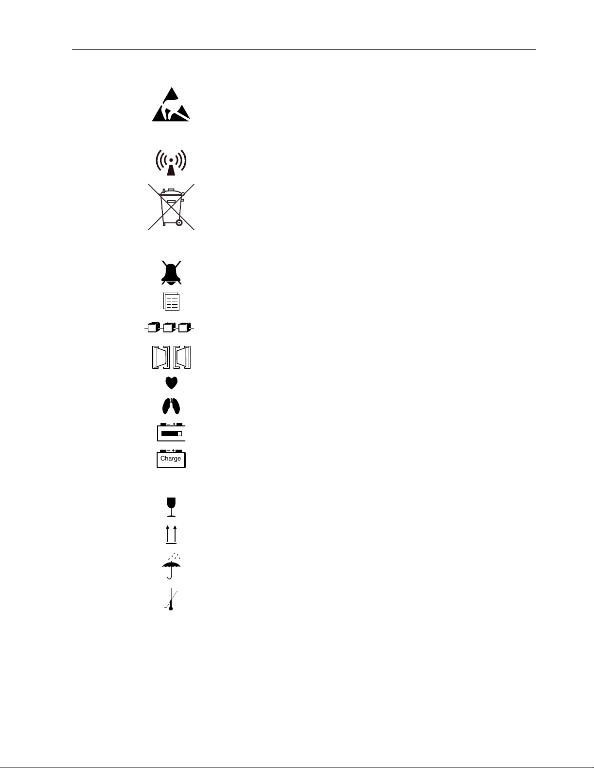
ESD warning symbol for electrostatic sensitive devices. Pins of connectors identified
with the ESD warning symbol should not be touched. Connections should not be
made to these connectors unless ESD precautionary procedures are used. See
"Safety precautions: ESD precautionary procedures" in the “User’s Reference
Manual” for details.
Symbol for non-ionizing electromagnetic radiation. Interference may occur in the
vicinity of equipment marked with the symbol.
This symbol indicates that the waste of electrical and electronic equipment must not
be disposed as unsorted municipal waste and must be collected separately. Please
contact an authorized representative of the manufacturer for information concerning
the decommissioning of your equipment.
Symbols on screens
When displayed on the upper left corner of the screen, indicates alarms are silenced.
When in the menu or digit fields, indicates that the alarm source has been turned off.
Sub menu. Selecting an alternative with this symbol in a menu opens a new menu.
Overview
The monitor is connected to the Monitor Network.
Data card (green) and/or Menu card (white) is inserted.
Indicates the beats detected.
Respiration rate is measured using impedance respiration measurement.
Back-up battery operation and remaining capacity.
Back-up battery charging.
Symbols on transport packaging
The contents of the package are fragile and have to be handled with care.
Indicates the correct upright position of the transport package.
The package must be kept in a dry environment.
The package should be kept within the indicated temperature limitations.
1-7
Page 16

Cardiocap/5 Technical Reference Manual
1.5 Safety precautions
1.5.1 Warnings
Refer to the User’s Reference Manual for additional warnings to be observed while monitoring a patient.
A WARNING indicates a situation in which the user or the patient may be in danger of injury or
death.
Installation
The monitor or its components should not be used adjacent to or stacked with other equipment. If
adjacent or stacked use is necessary, the monitor and its components should be observed to verify
normal operation in the configuration in which it will be used.
Pins of connectors identified with the ESD warning symbol should not be touched. Connections should
not be made to these connectors unless ESD precautionary procedures are used. For details, see
section “1.5.3 ESD precautionary procedures”.
After transferring or reinstalling the monitor, always check that it is properly connected and all parts
are securely attached. Pay special attention to this in case of stacked mounting.
Do not use the monitor in high electromagnetic fields (for example, during MRI).
A printer or computer must be supplied from an additional transformer providing at least basic
isolation (isolating or separating transformer).
If you accidentally drop the monitor, have it checked by authorized service personnel prior to clinical
use.
To avoid explosion hazard, do not use the monitor in presence of flammable anesthetics. The monitor
measures only non-flammable anesthetics.
Do not touch the patient, table, instruments, modules or the monitor during defibrillation.
Power connection
Before connecting the power cord to the mains outlet, check that the local voltage and frequency
rating corresponds with the rating stated on the device plate on the rear panel of the monitor.
Use only hospital-grade grounded power outlets and power cord. Do not remove the grounding pin
from the power plug.
Use only an intact power cord. Replace the cord if it is cracked, frayed, broken, or otherwise damaged.
Do not apply tension to the power cord otherwise the cord may get damaged.
Do not use an additional multiple socket outlet, extension cord or adapters of any kind.
Before starting to use the system, ensure that the whole combination complies with the international
standard IEC 60601-1-1 and with the requirements of the local authorities. Do not connect any
external devices to the system other than those specified.
1-8
To avoid the risk of electric shock, this equipment must only be connected to a supply mains with
protective earth.
External connection
Do not connect any external devices to the monitor other than those specified.
Page 17

Overview
Electrical shock hazard
When you connect equipment to the Cardiocap/5 input and output connectors, you are configuring a
medical system and are responsible for ensuring that the system complies with IEC/EN 60601-1-1
and with local requirements.
Do not touch any exposed wire or conductive surface while covers are off and the monitor is energized.
The voltages present can cause injury or death.
Always perform an electrical safety check and leakage current test of the monitor after service.
Fuse replacement
Replace a fuse only with one of the same type and rating.
Explosion hazard
To avoid explosion hazard do not use the monitor in the presence of flammable anesthetics.
Patient safety
Do not perform any testing or maintenance on the monitor while it is being used on a patient.
Never install the monitor so that it is above the patient.
The monitor must not be used without manufacturer approved mounting attached.
Operation of the monitor outside the specified values may cause inaccurate results.
To prevent erroneous readings, do not use physically damaged sensors or sensor cables. Discard a
damaged sensor or sensor cable immediately. Never repair a damaged sensor or cable; never use a
sensor or cable repaired by others. A damaged sensor or a sensor soaked in liquid may cause burns
during electrosurgery.
PATIENTS WITH PACEMAKERS OR ARRHYTHMIAS: Monitor may count the pacemaker pulses as heart
beats during cardiac arrest, some arrhythmias, and with certain types of pacemakers particularly in
ON R mode. Do not rely entirely upon rate meter alarms. Keep patients with pacemakers and
arrhythmias under close surveillance.
PACEMAKER PATIENTS: The impedance respiration measurement may cause rate changes in Minute
Ventilation Rate Responsive Pacemakers. In this case, set the pacemaker rate responsive mode off or
turn the monitor impedance respiration measurement off.
Temperature probes
To prevent injury, use Datex-Ohmeda temperature probes only.
Cleaning and service
Only trained personnel with proper tools and test equipment should perform the tests and repairs
described in this manual. Unauthorized service may void the monitor warranty.
Always unplug the monitor before cleaning or service. After cleaning or service ensure that every part
of the monitor is dry before reconnecting it to the power supply.
Do not touch any exposed wire or conductive surface while any cover is removed and the monitor is
energized. The voltages present can cause injury or death.
Pins of connectors identified with the ESD warning symbol should not be touched. Connections should
not be made to these connectors unless ESD precautionary procedures are used. For details, see
section “1.5.3 ESD precautionary procedures”.
1-9
Page 18

Cardiocap/5 Technical Reference Manual
Always perform an electrical safety check and a leakage current test on the monitor after service.
Handle the water trap and its contents as you would any body fluid. Infectous hazard may be present.
Accessories
Use only accessories, mounts and defibrillator-proof cables and invasive pressure transducers
approved by GE Healthcare. For a list of approved supplies and accessories, see the "Supplies and
Accessories" catalog. Other cables, transducers and accessories may cause a safety hazard, damage
the equipment or system, result in increased emissions or decreased immunity of the equipment or
system or interfere with the measurement. Protection against cardiac defibrillator discharge is due in
part to the accessories for pulse oximetry (SpO
measurement.
Single-use accessories are not designed to be reused. Reuse may cause a risk of contamination
and/or affect the measurement accuracy.
1.5.2 Cautions
Refer to the User’s Reference Manual for additional cautions to be observed while monitoring a patient.
A CAUTION indicates a condition that may lead to equipment damage or malfunction.
), temperature (T) and invasive pressure (P)
2
General
US Federal law restricts this device to sale by or on the order of a licensed medical practitioner.
Do not apply pressurized air to any outlet or tubing connected to the monitor. Pressure may destroy
sensitive elements.
Turn off the power before making any rear panel connections.
Use only cables and accessories approved by GE Healthcare. Other cables and accessories may
damage the system or interfere with measurement.
Vibrations during transport may disturb SpO
, ECG, impedance respiration, and NIBP measurements.
2
Installation
Leave space for air circulation to prevent the monitor from overheating.
Before use
Allow two minutes for warm-up and note any error messages or deviations from normal operation.
Airway gas measurement
Strong scavenging suction may change the operating pressure of the monitor and cause inaccurate
readings or internal damage.
Autoclaving and sterilizing
Do not steam autoclave or gas sterilize the monitor.
1-10
Cleaning and service
Do not use hypochlorite, ammonia-based, phenol-based, or acetone-based cleaners. These cleaners
may damage the surface of the monitor.
Do not immerse any part of the monitor in liquid or allow liquid to enter the interior.
Page 19

Overview
Do not apply pressurized air to any outlet or tubing connected to the monitor.
Clean the fan dust filter on the rear panel once a month or whenever necessary.
Electrostatic discharge through the PC boards may damage the components. Before handling printed
circuit boards, wear a static control wrist strap. Handle all boards by their nonconductive edges and
use antistatic containers when transporting them.
Do not break or bypass the patient isolation barrier when testing PC boards.
If liquid has accidentally entered the system or its parts, disconnect the power cord from the power
supply and have the equipment serviced by authorized service personnel.
Batteries
• A lithium battery on the CPU Board. Dispose of the faulty IC containing the battery
according to local regulations.
The battery package of the power supply unit in this device contains lead, which is hazardous to the
environment. Dispose of the battery according to local regulations.
To replace the batteries safely, please refer to the instructions in this manual.
• Do not short-circuit the battery terminals. Short-circuiting the battery may produce a very high
current, which damages the battery and may cause injury to personnel.
• Do not dispose of the battery into open flame, nor put the battery near fire, as it may explode.
• Do not disassemble the battery. It contains electrolyte, which may damage clothing or cause
injury to skin or eyes. If exposed to electrolyte, wash the injured area with plenty of water and
contact a doctor.
See Symbols on equipment earlier in this chapter.
Special components and modifications
Special components used in this monitor are vital to assure reliability and safety. GE Healthcare
assumes no responsibility for damage if replacement components not approved by GE Healthcare are
used.
The manufacturer accepts no responsibility for modifications made to the monitor outside the factory.
Storage and transport
Do not store or transport the monitor outside the specified temperature, pressure and humidity
ranges:
Temperature -10 to +50 °C (14 to 122°F)
Ambient pressure 660 to 1060 hPa (500 to 800 mmHg)
660 to 1060 mbar
Relative humidity 0 to 85 % non-condensing
1.5.3 ESD precautionary procedures
• To avoid electrostatic charges building up, it is recommended to store, maintain and use the
equipment at a relative humidity of 30% or greater. Floors should be covered by ESD
dissipative carpets or similar. Non-synthetic clothing should be used when working with the
component.
• To prevent applying a possible electrostatic discharge to the ESD sensitive parts of the
equipment, one should touch the metallic frame of the component or a large metal object
1-11
Page 20

Cardiocap/5 Technical Reference Manual
located close to the equipment. When working with the equipment and specifically when the
ESD sensitive parts of the equipment may be touched, a grounded wrist strap intended for
use with ESD sensitive equipment should be worn. Refer to the documentation provided with
the wrist straps for details of proper use.
ESD precautionary procedure training
• It is recommended that all potential users receive an explanation of the ESD warning symbol
and training in ESD precautionary procedures.
• The minimum contents of an ESD precautionary procedure training should include an
introduction to the physics of electrostatic charge, the voltage levels that can occur in normal
practice and the damage that can be done to electronic components if they are touched by
an operator who is electrostatically charged. Further, an explanation should be given of
methods to prevent build-up of electrostatic charge and how and why to discharge one’s
body to earth or to the frame of the equipment or bond oneself by means of a wrist strap to
the equipment or the earth prior to making a connection.
1.5.4 Disposal
Dispose of the whole device, parts of it, its packing material and this manual in accordance with local
environmental and waste disposal regulations.
1.5.5 Points to note
Medical electrical equipment needs special precautions regarding electromagnetic compatibility and
needs to be installed and put into service by qualified personnel according to the electromagnetic
compatibility information provided in Chapter 2.
Portable and mobile RF communications equipment can affect the medical electrical equipment.
Service and reparations are allowed for authorized service personnel only.
1.6 Specifications
All product specifications are subject to change without prior notice.
1.6.1 F-MX and F-MXG frames
Power supply
Rated voltages and frequencies: 100 to 240 VAC 60/50 Hz
Allowed voltage fluctuations: ± 10%
Maximum power consumption: 80 VA
Fuses (2): T2AH/250V
Environmental conditions
Operating temperature: +10 to +40 °C (50 to 104 °F)
Storage and transport temp: –10 to +50 °C (14 to 122 °F)
Relative humidity: 10 to 85 % noncondensing, in airway 0 to 100 % condensing
Atmospheric pressure: 660 to 1060 hPa (500 to 800 mmHg)
1-12
Page 21

Mechanics
Dimension: 330 mm × 220 mm × 300 mm (width × depth × height)
Weight: <11.2 kg / <24.8 lbs (F-MXG with all options); <10.2 kg / <22.6 lbs (F-MX with all options)
LCD display
Display size: 10.4 inch
Display type: Active matrix color LCD display
Resolution: 640 × 480
Battery
Type: 12V 2.6AH, lead acid
Back-up battery time: at least 15 minutes when fully charged
Charging time: 5 hours (typical)
The green battery charge status LED is On when the battery is fully charged, on the holding voltage. The
LED flashes when the battery is being charged.
1.6.2 NIBP
Measurement range:
Pulse rate range accepted: 30 to 250 bpm
Typical measuring time: adults 23 seconds, infants 20 seconds
Overview
adult 25 to 260 mmHg (3.3 to 34.7 kPa)
child 25 to 195 mmHg (3.3 to 26.0 kPa)
infant 15 to 145 mmHg (2.0 to 19.3 kPa)
1.6.3 Temperature
Measurement range: 10 to 45°C (50 to 113°F)
Measurement accuracy: 25 to 45.0 °C ± 0.1 °C (77 to 113 °F ± 0.2 °F)
10 to 24.9 °C ± 0.2 °C (50 to 76.8 °F ± 0.4 °F)
Probe type: Compatible with Datex-Ohmeda temperature probes only
1.6.4 ECG
Waveform display (with 50 Hz power supply frequency):
Monitoring filter: 0.5 to 30 Hz
ST filter: 0.05 to 30Hz
Diagnostic filter: 0.05 to 100 Hz
Waveform display (with 60 Hz power supply frequency):
Monitoring filter: 0.5 to 40 H
ST filter: 0.05 to 40 Hz
Diagnostic filter: 0.05 to 100 Hz
Heart rate
Measurement range: 30 to 250 bpm
Measurement accuracy: ± 5% or ± 5
Pacemaker pulse detection level: 2 to 500 mV
Pacemaker pulse duration: 0.5 to 2 ms
1-13
Page 22

Cardiocap/5 Technical Reference Manual
1.6.5 Impedance respiration
Respiration range: 4 to 120 respirations/minute
Accuracy: ± 5% or ± 5 bpm
1.6.6 Pulse oximetry, standard
Display update time: 5 seconds
Averaging time: adjustable
Plethysmographic waveform scaling: adjustable
SpO2
Calibration range: 50 to 100%
Calibrated against functional saturation
Measurement range: 40 to 100%
Measurement accuracy (% SpO
80 to 100% ± 2 digits;
50 to 80% ± 3 digits;
Below 50% unspecified
NOTE: SpO
measurement accuracy is based on deep hypoxia studies using Datex-Ohmeda FingerSat
2
sensors on volunteered subjects. Arterial blood samples were analyzed by a Radiometer OSM
CO-oximeter. Refer to the sensor instructions for specific SpO
±1 SD):
2
accuracy data.
2
Pulse rate
Measurement range: 30 to 250 bpm
Measurement accuracy: ± 5% or ± 5 bpm
Default alarm limits
: high Off, low 90%
SpO
2
Pulse rate: high 160, low 40
NOTE: Limits are adjustable.
Sensor emitter wavelength ranges
Red LED: 660 nm
Infrared LED: 900 nm
1.7 Specifications for options
1.7.1 Classifications
According to IEC 60601-1
• CLASS I EQUIPMENT and INTERNALLY POWERED EQUIPMENT according to the type of
protection against electrical shock.
• TYPE BF or CF equipment according to the degree of protection against electric shock is
indicated by a symbol beside each patient connector.
1-14
• Degree of protection against harmful ingress of water as detailed in the IEC 60529:
Monitor: IPX1, vertically falling water drops shall have no harmful effects (applicable when the
monitor is in upright position, or tilted backwards). In the protective case IPX4, splash proof,
only when the case is closed properly, the monitor is intact and operates on battery power.
Page 23

Power adapter: IPX0, ordinary equipment.
Power adapter for Transport Vehicles: IPX1.
• EQUIPMENT not suitable for use in the presence of a FLAMMABLE ANAESTHETIC MIXTURE with
air or with oxygen or nitrous oxide.
• CONTINUOUS OPERATION according to the mode of operation.
• CISPR 11: Group 1, Class A.
Group 1 contains all ISM (Industrial, scientific and medical) equipment in which there is
intentionally generated and/or used conductively coupled radio-frequency energy which is
necessary for the internal functioning of the equipment itself.
Class A equipment is suitable for use in all establishments other than domestic and those
directly connected to the public low-voltage power supply network that supplies buildings used
for domestic purposes.
Classification according to EU Medical Device Directive
• The monitor is classified as IIb.
1.7.2 Pulse oximetry, Datex-Ohmeda enhanced (N-XOSAT)
Display update time: 5 seconds
Averaging time: 12 seconds
Plethysmographic waveform scaling: automatic
Overview
SpO
2
Calibration range: 70 to 100%
Calibrated against functional saturation
Measurement range: 1 to 100%
Measurement accuracy (% SpO
±1 SD):
2
70 to 100% ± 2 digits
70 to 100% ± 3 digits during conditions of clinical patient motion
Below 70% unspecified
NOTE: SpO
measurement accuracy is statistically derived and correlated to simultaneous arterial
2
blood gases measured on a Radiometer OSM3 CO-oximeter. Refer to the sensor instructions for
specific accuracy data.
Pulse rate
Measurement range: 30 to 250 bpm
Measurement accuracy: ± 2% or ± 2 bpm (whichever is greater)
Default alarm limits
: high Off, low 90%
SpO
2
Pulse rate: high 160, low 40
NOTE: Limits are adjustable.
Sensor emitter wavelength ranges
Red LED: 650 to 665 nm
Infrared LED: 930 to 950 nm
Average power: ≤ 1 mW
1-15
Page 24

Cardiocap/5 Technical Reference Manual
1.7.3 Pulse oximetry, Nellcor compatible (N-XNSAT)
Display update time: 5 seconds
Averaging time: 5 to 7 seconds
Plethysmographic waveform scaling: automatic
SpO
2
Calibrated against functional saturation
Measurement range: 1 to 100%
Measurement accuracy (% SpO
70 to 100% (± 2 digits to ± 3.5 digits, depending on the sensor)
Below 70% unspecified
See the User's Reference Manual (Pulse Oximetry chapter) for a list of approved sensors and accuracy
details.
NOTE: SpO
Pulse rate
Measurement range: 30 to 250 bpm
Measurement accuracy: ± 3 digits
measurement accuracy is based on testing healthy adult volunteers in induced hypoxia
2
studies.
±1 SD):
2
Default alarm limits
SpO
: high Off, low 90%
2
Pulse rate: high 160, low 40
NOTE: Limits are adjustable.
Sensor emitter wavelength ranges
Red LED: 660 nm
Infrared LED: 920 nm
1.7.4 Invasive blood pressure (N-XP)
Measurement range: –40 to 320 mmHg (-5.3 to 42.7 kPa)
Measurement accuracy: ± 5% or ± 2 mmHg
Transducer sensitivity: 5 µV/V/mmHg, 5 Vdc, max 20 mA
Pulse rate
Measurement range: 30 to 250 bpm
Accuracy: ± 5% or ± 5 bpm
1.7.5 Airway gases (N-XC, N-XCO, and N-XCAiO)
Accuracy specifications apply in normal conditions.
General
Airway humidity: 0 to 100%, condensing
Sampling rate: 200 ± 20 ml/min. (sampling line 2, 3 and 6 m, normal conditions)
Sampling delay: 2.5 seconds typical with a 3 m sampling line
3.4 seconds typical with a 6 m sampling line
Total system response time: 2.9 seconds typical with a 3 m sampling line, including sampling delay
and rise time
4.4 seconds typical with a 6 m sampling line
Value update rate: breath-by-breath
1-16
Page 25

Overview
Automatic compensation for pressure, CO2-N2O and CO2-O2 collision broadening effect
Warm-up time:
2 minutes for operation with CO
, O2, and N2O
2
5 minutes for operation of anesthetic agents
30 minutes for full specifications
Autozeroing interval:
immediately after “Calibrating gas sensor” message and
2, 5, 10, 15, 30, 45, 60 minutes after start-up, then every 60 minutes
Respiration rate (RR)
Measurement range: 4 to 60 breaths/minute
Detection criteria: 1 % variation in CO2
Carbon Dioxide (CO2), Oxygen (O2), and Nitrous Oxide (N2O)
Measurement Carbon Dioxide (CO2) Oxygen (O2) Nitrous Oxide (N2O)
Range
Rise time
Accuracy
(typical value)
Gas cross effects
0 to 15 vol%, (0 to 15 kPa)
(0 to 113 mmHg)
< 400 ms typical < 400 ms typical < 400 ms typical
± (0.2 vol% + 2 % of reading) ± (1 vol% + 2 % of
< 0.2 vol%
(O
, N2O, and anesthetic agents)
2
0 to 100% 0 to 100%
± (2 vol% + 2% of reading)
reading)
< 1 vol% (anesthetic
agents);
< 2 vol% (N2O)
(0%< N2O<85%)
± (2 vol% + 8% of reading)
(85%< N2O<100%)
(anesthetic agents)
< 2 vol%
NOTE:
• If CO
• O
concentration is below 0.1%, 0.0% is displayed.
2
Fi-Et difference: resolution 0.1 vol%
2
Anesthetic agents (AA)
Resolution is two digits when the AA concentration is below 1.0 vol%.
If AA concentration is below 0.1 vol%, 0.0% is displayed.
Measurement Halothane, Isoflurane, Enflurane Sevoflurane Desflurane
Range
Rise time
Accuracy
(typical value)
Gas cross effects
< 600 ms (<1 000 ms for Hal)
typically with a 3 m sampling line
< 650 ms (<1 050 ms for Hal)
typically with a 6 m sampling line
± (0.15 vol% + 5 % of reading) ± (0.15 vol% + 5 % of
0 to 6% 0 to 8% 0 to 20%
< 600 ms typically with
a 3 m sampling line
< 650 ms typically with
a 6 m sampling line
reading)
< 0.15 vol% N2O < 0.15 vol% N2O < 0.15 vol% N2O
< 600 ms typically with
a 3 m sampling line
< 650 ms typically with
a 6 m sampling line
± (0.15 vol% + 5 % of
reading)
Agent identification
Identification threshold: 0.15 vol% typically
Identification time: < 20 seconds (for pure agents)
Mixture identification threshold for 2nd agent: 0.2 vol% +10% of total conc.
1-17
Page 26

Cardiocap/5 Technical Reference Manual
MAC
Range: 0 to 9.9 MAC
Equation:
MAC( AA) =
%(ETAA)
x(AA)
%
+
2
ETN O
100
where x(AA): Hal = 0.75%, Enf = 1.7%, Iso = 1.15%, Sev = 2.05%, Des = 6.0%.
Normal conditions
After 30-minute warm-up period:
Ambient temperature: 18 to 28 °C, within ± 5 °C of calibration
Ambient pressure: 500 to 800 mmHg, ± 50 mmHg of calibration
Ambient humidity: 20 to 80% RH, ± 20% RH of calibration
Non-disturbing gases:
Ethanol C
Acetone (< 0.3%)
Methane CH
Nitrogen N
Carbon monoxide CO
Nitric oxide NO (< 200 ppm)
Water vapor
Maximum effect on readings:
< 0.2 vol%
CO
2
O2, N2O < 2 vol%
Anesthetic agents < 0.15 vol%
Effect of helium: decreases CO
decreases O
Effect of Xenon: decreases CO
Effect of anesthetic agents to monitors without anesthetic measurement:
decreases CO
OH (< 0.3%)
2H5
(< 0. 3%)
4
2
readings < 0.6 vol% typically
2
readings < 3 vol% typically
2
readings < 0.4 vol% typically
2
readings < 0.5 vol% typically
2
1-18
Conditions exceeding normal
Accuracy specifications under conditions n o p q:
n Ambient temperature: 10 to 40 °C, within ± 5 °C of calibration
Ambient pressure: 500 to 800 mmHg, ± 50 mmHg of calibration
Ambient humidity: 10 to 98% RH, ± 20% RH of calibration (non-condensing)
Respiration rate: 35 to 60 breaths per minute
o During warm-up, 2 to 10 minutes (anesthetic agents 5-10 minutes) under normal conditions
p During warm-up, 10 to 30 minutes under normal conditions
O > 85%
q N
2
Page 27

Overview
Parameter
CO2
O2
N2O
Agents (Des, Enf, Hal, Iso, Sev)
Parameter
CO2
O2
N2O
Agents (Des, Enf, Hal, Iso, Sev)
Parameter
CO2
O2
Accuracy under Condition
n
± (0.3 vol% + 4% of reading); at 5 vol% error ± 0.5 vol%
± (2 vol% + 2% of reading)
± (3 vol% + 3% of reading
± (0.2 vol% + 10% of reading)
Accuracy under Condition
o
± (0.4 vol% + 7% of reading); at 5 vol% error ± 0.75 vol%
± (3 vol% + 3% of reading)
± (3 vol% + 5% of reading)
± (0.3 vol% + 10% of reading)
Accuracy under Condition
p
± (0.3 vol% + 4% of reading); at 5 vol% error ± 0.5 vol%
± (2 vol% + 2% of reading)
N2O
Agents (Des, Enf, Hal, Iso, Sev)
Parameter
N2O
1.7.6 Patient Spirometry (N-XV)
Accuracy specifications apply in normal conditions.
After 10-minute warm-up period
Ambient temperature: 10 to 40 °C
Ambient pressure: 500 to 800 mmHg
Ambient humidity: 10 to 98% RH
Airway humidity: 10 to 100% RH
Respiration rate: 4 to 35 breaths/minute (adult); 4 to 50 breaths/minute (pediatric)
I:E ratio: 1:4.5 to 2:1
Intubation tube: 5.5 to 10 mm (adult); 3 to 6 mm (pediatric)
± (3 vol% + 3% of reading
± (0.2 vol% + 10% of reading)
Accuracy under Condition
q
± (2 vol% + 8% of reading)
1-19
Page 28

Cardiocap/5 Technical Reference Manual
Detection through D-lite™ or Pedi-lite™ flow sensor and gas sampler:
Measurement D-lite flow sensor (adult) Pedi-lite flow sensor (pediatric)
Tidal volume
Measurement range
Resolution
Accuracy (typical value)
Minute volume
Measurement range
Resolution
Accuracy (typical value)
Airway pressure (Paw)
Measurement range
Resolution
Accuracy (typical value)
Airway flow
Measurement range
(for both directions)
Compliance
Measurement range
Resolution
Airway resistance (Raw)
Measurement range
Resolution
150 to 2000 ml
1 ml
± 6% or 30 ml (whichever is
larger)
2 to 20 l/minute
0.1 l/minute
± 6%
–20 to +100 cmH
0.5 cmH
O
2
O
2
± 1 cmH2O
1.5 to 100 l/minute
4 to 100 ml/cmH
O
2
1 ml/cmH2O
O/ l/s
2
O/l/second
2
0 to 40 cm H
1 cmH
15 to 300 ml
1 ml
± 6% or 4 ml (whichever is
larger)
0.5 to 5 l/minute
0.1 l/minute
± 6%
–20 to +100 cmH
0.5 cmH
O
2
O
2
not applicable
0.25 to 25 l/minute
1 to 100 ml/cmH
O
2
0.1 ml/cmH2O
0 to 40 cm H
1 cmH
O/ l/s
2
O/l/second
2
Sensor specifications
Dead space
Resistance at 30 l/minute
Resistance at 10 l/minute
9.5 ml
0.5 cmH
O
2
not applicable
Conditions exceeding normal
Accuracy specifications during warm-up (first 2 to 10 minutes after power is turned on):
Airway pressure (P
) accuracy: ± 2 cmH2O
aw
Tidal volume accuracy: ± 10% or 100 ml (adult); ± 10% or 10 ml (pediatric)
1.7.7 NeuroMuscular Transmission (N-XNMT)
NMT stimulation modes
Stimulation modes
Train of four (TOF)
Double burst, 3.3 (DBS)
Single twitch (ST)
50 Hz tetanic + post tetanic count (PTC)
Measurement intervals (TOF and DBS): manual; 10 seconds, 12 seconds, 15 seconds, 20 seconds,
1 minute, 5 minutes, 15 minutes
Measurement intervals (ST): manual; 1 second, 10 seconds, 20 seconds
2.5 ml
not applicable
1.0 cmH
O
2
1-20
Page 29

Stimulator
Stimulus pulse: Square wave, constant current
Pulse width: 100, 200 or 300 µs
Stimulus current range (supramax and manual): 10 to 70 mA with 5 mA steps
Stimulus current accuracy: 10% or ±3 mA (whichever is greater)
Maximum load: 3 kΩ
Maximum voltage: 300 V
Regional block mode
Stimulation modes: Single twitch
Intervals: 1 second, 2 seconds, 3 seconds
Stimulus pulse: Square wave, constant current
Pulse width: 40 µs
Stimulus current range: 0 to 5.0 mA with 0.1 mA steps
Stimulus current accuracy: 20% or 0.3 mA (whichever is greater)
1.7.8 Recorder (N-XREC)
Principle: thermal array
Print resolution
Vertical: 8 dots/mm (200 dots/inch)
Horizontal: 32 dots/mm (800 dots/inch) at speed of 25 mm/second and slower
Paper width: 50 mm, printing width 48 mm
Traces: selectable; 1, 2, or 3 traces
Print speed: 1, 6.25, 12.5, 25 mm/second
Overview
1-21
Page 30

Cardiocap/5 Technical Reference Manual
1-22
Page 31

Chapter 2. Installation and Functional Check
2.1 Introduction......................................................................... 2-1
2.2 Installation .......................................................................... 2-1
2.2.1 Front panel components.............................................................................. 2-1
Patient connectors panel (F-MX)................................................................... 2-2
Patient connectors panel (F-MXG) ................................................................ 2-3
2.2.2 Rear panel ................................................................................................. 2-4
2.2.3 Connection to network ................................................................................ 2-5
2.2.4 Sample gas exhaust connections................................................................. 2-5
2.2.5 Scavenging through the ventilator reservoir................................................... 2-5
2.2.6 Scavenging through the anesthesia gas scavenging system ........................... 2-6
2.2.7 Connecting directly to a vacuum scavenging system...................................... 2-6
2.2.8 Returning gas to the patient circuit ............................................................... 2-7
2.3 Choosing the location ........................................................... 2-7
Contents
2.4 Interfacing........................................................................... 2-7
2.4.1 Interfacing a printer..................................................................................... 2-7
2.4.2 Interfacing a computer................................................................................ 2-8
2.4.3 Interfacing other devices using the analog/digital output connector................ 2-8
Digital outputs ............................................................................................ 2-8
Analog outputs ........................................................................................... 2-9
2.4.4 Setting the analog output signals............................................................... 2-10
2.5 Connector pin assignments................................................. 2-11
2.5.1 Analog/digital output connector (X1)..........................................................2-11
2.5.2 RS-232 serial communication interface/local printer connector (X2) ............2-12
2.5.3 Network identification plug connector (X3).................................................. 2-12
2.5.4 Ethernet connector (X4)............................................................................. 2-13
2.5.5 Remote Control connector (X5) .................................................................. 2-13
2.6 Functional check................................................................ 2-14
Using the Functional Check Form................................................................ 2-14
Recommended tools................................................................................. 2-14
2.6.1 Functional inspection................................................................................ 2-15
Recorder test (if N-XREC option is included) ................................................ 2-17
Memory card (PCMCIA) test (if N-XDNET option is included).......................... 2-17
Network test (if N-XNET or N-XDNET option is included).................................2-18
ECG board test.......................................................................................... 2-19
STP board test ..........................................................................................2-19
NIBP board test......................................................................................... 2-20
Pulse oximetry test (if N-XOSAT or N-XNSAT option is included) .....................2-20
Gas measurement and spirometry test........................................................ 2-21
NeuroMuscular Transmission (NMT) test (if N-XNMT option is included) ......... 2-22
2.6.2 Performance checks ................................................................................. 2-24
Page 32

Cardiocap/5 Technical Reference Manual
Table of Figures
Figure 2-1. Cardiocap/5 monitor (F-MXG) .........................................................................2-1
Figure 2-2. Patient connections—Hemodynamic (F-MX)......................................................2-2
Figure 2-3. Patient connections—Hemodynamic with gas (F-MXG).......................................2-3
Figure 2-4. Rear panel (F-MXG).........................................................................................2-4
Figure 2-5. Scavenging through ventilator reservoir ............................................................ 2-5
Figure 2-6. Connecting sample gas outlet directly to an anesthesia gas scavenging system... 2-6
Figure 2-7. Gas return to patient circuit in AS/3 ADU.......................................................... 2-7
Page 33

2. INSTALLATION AND FUNCTIONAL CHECK
2.1 Introduction
This chapter includes the information needed to install and check the monitor. Information for
connecting other equipment, such as a printer or computer, is also included. If you need assistance
concerning the installation, please contact your authorized distributor.
2.2 Installation
2.2.1 Front panel components
Installation and Functional Check
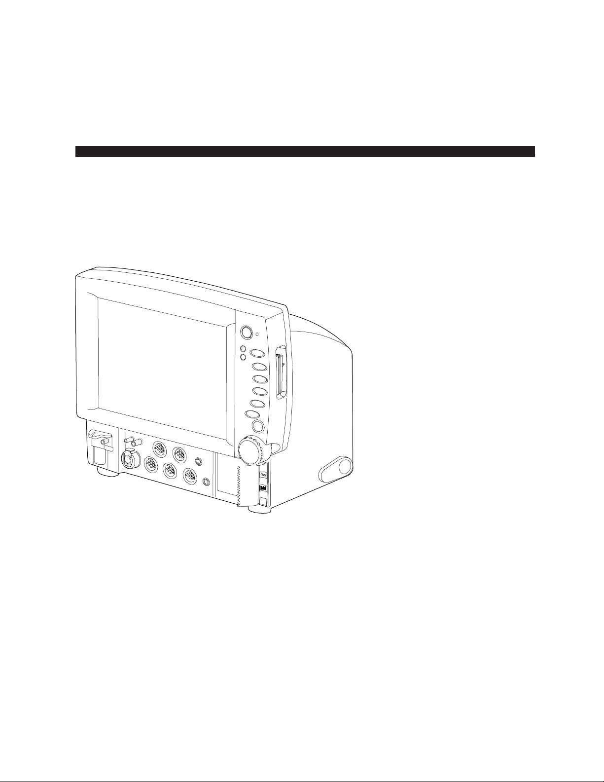
Figure 2-1. Cardiocap/5 monitor (F-MXG)
(1) Power On/standby key
(2) External power indicator / Battery charge status LED
(3) Alarm indicators
(4) Insertion slots for memory cards (Data card and Menu card)
A cover for the slots is available. See the Spare Parts chapter later in this manual.
(5) Direct access keys
(6) Adjustable rear support
(7) ComWheel
2-1
Page 34

Cardiocap/5 Technical Reference Manual
(8) Recorder (N-XREC option)
NOTE: The two-button recorder (shown) is for Cardiocap/5 monitors using software version 3.0
or higher. A one-button recorder was available previously.
(9) Patient connectors
(10) Spirometry connectors
(11) NIBP connector
(12) D-fend housing (F-MXG only)
Patient connectors panel (F-MX)
T2
NIBP
ECG SpO2
1 2 3 4 5 6 7
P1
P2 T1
Figure 2-2. Patient connections—Hemodynamic (F-MX)
(1) NIBP
(2) ECG
(3) SpO
2
NOTE: Connector type depends on which SpO
option is installed:
2
Connector for Datex-Ohmeda
standard pulse oximetry
Connector for Datex-Ohmeda
enhanced pulse oximetry
Connector for Nellcor® compatible
pulse oximetry
2-2
(4) Invasive pressure, P1 (N-XP option)
(5) Invasive pressure, P2 (N-XP option)
(6) Temperature, T2 (N-XP option)
(7) Temperature, T1
Page 35

Patient connectors panel (F-MXG)
1 2 3 4
Installation and Functional Check
NIBP
Spiromet ry
NMT
ECG
SpO2
P2
T2
P1
T1
569 8 710
Figure 2-3. Patient connections—Hemodynamic with gas (F-MXG)
(1) Spirometry (N-XV option)
(2) NMT (N-XNMT option)
(3) Invasive pressure, P2 (N-XP option)
(4) Temperature, T2 (N-XP option)
(5) Temperature, T1
(6) Invasive pressure, P1 (N-XP option)
(7) SpO
2
NOTE: Connector type depends on which SpO
Connector for Datex-Ohmeda
standard pulse oximetry
option is installed:
2
(8) ECG
(9) NIBP
(10) D-fend housing
Connector for Datex-Ohmeda
enhanced pulse oximetry
Connector for Nellcor® compatible
pulse oximetry
2-3
Page 36

Cardiocap/5 Technical Reference Manual
2.2.2 Rear panel
1
13
12
Figure 2-4. Rear panel (F-MXG)
(1) Built-in handle
(2) Gas outlet (F-MXG only), X6
(3) Remote Control connector, X5
(4) Ethernet connector, X4
(5) Network connection LEDs
(6) Network identification plug connector, X3
(7) Serial communication interface/local printer connector, X2
(8) Analog/digital output connector, X1
(includes nurse call and defibrillator synchronization signals)
2
3
4
567891011
2-4
(9) Mounting attachment
(10) Dust filter
(11) Potential equalization
(12) Fuse and voltage information
(13) Receptacle for mains power cord and fuses
WARNING: Electrical shock hazard. Connect the power cord to a three-wire, grounded, hospitalgrade receptacle only.
CAUTION: Turn off the power before making any rear panel connections.
Page 37

2.2.3 Connection to network
If either Cardiocap/5 Network option (N-XNET or N-XDNET) is installed, you can connect the
Cardiocap/5 to the Datex-Ohmeda Network and iCentral. Use the Monitor-Network cable to connect
the monitor to the network.
1. Power off the monitor.
2. On the rear panel, connect one of the RJ-45 connectors to connector X4 and connect the
Identification Plug to connector X3.
3. Connect the other RJ-45 connector to the corresponding Datex-Ohmeda iCentral Network
connector on the wall box.
4. Power on the monitor.
5. Confirm that the network symbol and the “Connected to Network” message are displayed on the
upper part of the screen.
NOTE: The network symbol does not appear if the battery symbol is displayed.
Installation and Functional Check
2.2.4 Sample gas exhaust connections
When N2O or volatile anesthetics are used, take precautions against venting these gases into room air.
Return the sample gas to the patient circuit or connect the sample gas outlet of the monitor to the
scavenging system.
CAUTION: Strong scavenging suction may change the operating pressure of the monitor and cause
inaccurate readings or internal damage.
2.2.5 Scavenging through the ventilator reservoir
To scavenge through the ventilator reservoir:
Figure 2-5. Scavenging through ventilator reservoir
• Connect an exhaust line to the sample gas outlet on the rear panel of the monitor.
2-5
Page 38

Cardiocap/5 Technical Reference Manual
•
Attach the other end of the line to the ventilator reservoir. Make sure that the reservoir tube
diameter is at least 2-3 times larger than the exhaust line.
2.2.6 Scavenging through the anesthesia gas scavenging system
Anesthesia machines are equipped with an anesthesia gas scavenging system (AGSS), and in some
machines you can connect the sample gas outlet directly to that.
For example, connect the sample gas outlet to the Datex-Ohmeda S/5 Avance:
2-6
Figure 2-6. Connecting sample gas outlet directly to an anesthesia gas scavenging system
Note: Refer to the anesthesia machine’s documentation to find out where and how the sample gas
can be connected.
2.2.7 Connecting directly to a vacuum scavenging system
To scavenge through a direct connection:
1. Connect the exhaust line (733195, 5/pkg) to the sample gas outlet on the monitor.
2. Connect the exhaust line only to an open scavenging system where gas is removed at room
pressure. Do not connect the monitor directly to a vacuum scavenging system.
Page 39

2.2.8 Returning gas to the patient circuit
In some anesthesia machines, you can return the sample gas to the patient circuit, refer to the
anesthesia machines manuals. For example, if you use the Datex-Ohmeda S/5 Anesthesia Delivery
Unit (ADU), connect an optional adapter (881644, 5/pkg) to the patient breathing tubes.
Figure 2-7. Gas return to patient circuit in AS/3 ADU
Installation and Functional Check
2.3 Choosing the location
The monitor can be placed on a flat surface or hung with the handle from the bed or wall rails. Make
sure that the surface or rail holds up to at least 13 kg/29 lb.
WARNING: The monitor or its components should not be used adjacent to or stacked with other
equipment. If adjacent or stacked use is necessary, the monitor and its components should be
observed to verify normal operation in the configuration in which it will be used.
When choosing the location, refer to the EMC guidance in the appendix later in this document.
2.4 Interfacing
WARNING: Electrical shock hazard. When you connect equipment to the Cardiocap/5 input and
output connectors, you are configuring a medical system and are responsible for ensuring that
the system complies with IEC/EN 60601-1-1 and with local requirements.
2.4.1 Interfacing a printer
You can connect a PCL-5 compatible laser printer to the Cardiocap/5 using the Datex-Ohmeda Light
Monitor–Printer cable. Connect this serial-to-parallel interface cable between the local printer
connector (X2) and the printer. For ordering details, refer to the Datex-Ohmeda Supplies &
Accessories Catalog.
WARNING: Connecting the power supply cord of the printer to the wall socket may cause the
printer leakage current to exceed the limit specified for medical equipment. Always connect the
printer to an appropriate isolation transformer.
2-7
Page 40

Cardiocap/5 Technical Reference Manual
2.4.2 Interfacing a computer
It is possible to interface a computer to the Cardiocap/5. For further information, please contact your
authorized GE Healthcare distributor.
WARNING: Connecting the power supply cord of the computer to the wall socket may cause the
computer leakage current to exceed the limit specified for medical equipment. Always connect
the computer to an appropriate separating transformer.
2.4.3 Interfacing other devices using the analog/digital output connector
The analog/digital output connector (X1) can be used to interface other devices to the Cardiocap/5.
Digital outputs
Defibrillation sync
The ECG generates the defibrillation sync digital output signal. The signal is set to a high state
(logic 1: 2.8 to 5.0 VDC ) when activated. After 10 ms, it is set back to a low state
(logic 0: 0 to 0.8 VDC). The signal is regenerated only after returning to the low state. The delay from
the R-wave peak to the start of the signal is 35 ms maximum.
Nurse call
The nurse call digital output signal is generated by red, yellow, and white alarms. When activated, the
signal is set to a high state and remains at a high state until the alarm situation is over or the Silence
Alarms key is pressed. The high state (logic 1) ranges from 2.8 to 5.0 VDC while the low state (logic 0)
ranges from 0 to 0.8 VDC. The nurse call signal also activates a relay that connects X1 (pins 11 and 12).
2-8
Page 41

Installation and Functional Check
Analog outputs
Each analog output signal is scaled linearly between –5 and +5 volts. The resolution is 4096 steps
over 10 volts, or approximately 0.00244 volts per step. All signal levels are updated every 10 ms.
OFF Default state. No signal is present at the analog output pin.
HR according to selected source (display value)
The original scale of 0 to 300 beats is scaled between 0 and 3 volts.
ECG1, ECG2, ECG3
The original scale of –5000 microvolts to +5000 microvolts is scaled between –5 and +5 volts.
P1 lre, P2 lre (Invasive pressure real-time values, low resolution)
The original scale of –20 mmHg to +320 mmHg (-2.7 to +42.7 kPa) is scaled between –0.2
and +3.2 volts.
P1 hre, P2 hre (Invasive pressure real-time values, high resolution)
The original scale of –20 mmHg to +50 mmHg (-2.7 to +6.7 kPa) is scaled between –2 and
+5 volts.
Pleth The original scale of –100% to 100% is scaled between –5 and +5 volts.
SpO
>40, SpO2>60, SpO2>80 (beat-to-beat, display value, 10 s average)
2
The original scale of 40 to 100% (SpO
(SpO2>80) is scaled between –5 and +5 volts.
>40), 60 to 100% (SpO2>60) or 80 to 100%
2
CO
The original scale of 0% to 10% is scaled between 0 and +5 volts. Values greater than 10%
2
are set to 10%. (Airway gas special indications are applied. See Special indications for
analog outputs below.)
AA (anesthetic agent)
The original scale of 0% to 10% is scaled between 0 and +5 volts. Values greater than 10%
are set to 10%. (Airway gas special indications are applied. See Special indications for
analog outputs below.)
The original scale of 0% to 100% is scaled between 0 and +5 volts. (Airway gas special
O
2
indications are applied. See Special indications for analog outputs below.)
O The original scale of 0% to 100% is scaled between 0 and +5 volts. (Airway gas special
N
2
indications are applied. See Special indications for analog outputs below.)
Paw (airway pressure)
The original scale of –20 cmH
O to +80 cmH2O is scaled between –5 and +5 volts. (Airway
2
gas sensor failure is applied. See Special indications for analog outputs below.)
Flow The original scale of –100 l/minute to +100 l/minute is scaled between –5 and +5 volts.
(Airway gas sensor failure is applied. See Special indications for analog outputs below.)
Volume The original scale of –2.5 liters to +2.5 liters is scaled between –5 and +5 volts. (Airway gas
sensor failure is applied. See Special indications for analog outputs below.)
Resp The original scale of –5000 mohms is scaled between –5 and +5 volts.
RR The respiration rate display of 0 to 150 breaths per minute is scaled between 0 and +1.5 volts.
T1, T2 The original temperature scale of 0 °C to 50 °C is scaled between 0 and +5 volts.
TEST SIGNALS –5 V, 0 V, +5 V
Steady signals with one of the listed values.
TEST 1 Test signal of a triangle shape with a base width of 1 second (0 V minimum; +5 V maximum).
2-9
Page 42

Cardiocap/5 Technical Reference Manual
TEST 2 Test signal of a triangle shape with a base width of 4 seconds (–5 V minimum; +5 V maximum).
Special indications for analog outputs
Start-up indication occurs when the monitor is started by a power on or by an internal restart (caused
by a fatal failure). The indication consists of three triangle-shaped signals with a base width of 1
second, base of 0 volts, and a height of 5 volts.
Airway gas calibration: During calibration of any gases, a square wave is generated. The minimum
value is 0 volts, the maximum value is +2 volts, the minimum phase length equals the maximum
phase length, and the frequency is 0.25 Hz.
Airway gas zeroing: During zeroing of any gases, a square wave is generated. The minumum value is
0 volts, the maximum value is +5 volts, the minimum phase length equals the maximum phase length,
and the frequency is 0.25 Hz.
Airway gas occlusion: During occlusion of any gases, a triangle-shaped signal is generated with a
base width of 4 seconds, a minimum value of 0 volts, and a maximum value of +5 volts.
Airway gas air leak: During an air leak of any gases, a triangle-shaped signal is generated with a base
width of 3 seconds, a minimum value of 0 volts, and a maximum value of +5 volts.
Airway gas sensor failure: During a sensor failure, a triangle-shaped signal is generated with a base
width of 2 seconds, a minimum value of 0 volts, and a maximum value of +5 volts.
2.4.4 Setting the analog output signals
To set the analog output signals:
1. Press the ComWheel and select Monitor Setup from the Main Menu.
2. Select Install/Service and enter the password (16-4-34).
3. Select Installation.
4. Select Analog Outputs and set the channels.
5. Press the Normal Screen key.
2-10
Page 43

2.5 Connector pin assignments
2.5.1 Analog/digital output connector (X1)
CON./ I/O BOARD SIGNAL DIRECTION LEVEL FUNCTION
X1/1 GND – 0V GND
X1/2 N/C
X1/3 DSYNCOUT O CMOS Defibrillation sync.
X1/4 N/C
X1/5 NCALLOUT O CMOS Nurse Call
X1/6 N/C
X1/7 GND – 0V GND
X1/8 to X1/10 N/C
X1/11 NCALLB1 – – Nurse call relay
X1/12 NCALLB2 – – Nurse call relay
X1/13 N/C
X1/14 A1OUT O Analog output
X1/15 +5VOUT – +5V +5 V output voltage
X1/16 N/C
X1/17 A3OUT O Analog output
X1/18 N/C
X1/19 A2OUT O Analog output
X1/20 A0OUT O Analog output
X1/21 to X1/37 N/C
X1/38 ECGOUT O Analog ECG-signal output
X1/39 to X1/43 N/C
X1/44 GND – 0V GND
Installation and Functional Check
2-11
Page 44

Cardiocap/5 Technical Reference Manual
2.5.2 RS-232 serial communication interface/local printer connector (X2)
Connector X2 provides an RS-232 serial communication link with handshaking.
D9 male connector pinout (front view)
CON./ I/O BOARD SIGNAL DIRECTION LEVEL FUNCTION
X2/1 GND – 0V Ground
X2/2 RXD I RS232 Serial bus, Receive
X2/3 TXD O RS232 Serial bus, Transmit
X2/4 +5VS – +5V +5 V output voltage, maximum 200 mA
X2/5 GND – 0V Ground
X2/6 N/C
X2/7 RTS O RS232 Serial bus, Request To Send
X2/8 CTS I RS232 Serial bus, Clear To Send
X2/9 N/C
2.5.3 Network identification plug connector (X3)
The coding element interface is used for bedside address-coding for the Ethernet. The element is
connected to the 9-pin female connector.
D9 female connector pinout (front view)
CON./ I/O BOARD SIGNAL DIRECTION LEVEL FUNCTION
X3/1 IDCS O CMOS ID chip select
X3/2 IDCLK O CMOS ID clock
X3/3 IDDI I CMOS ID data in
X3/4 IDDO O CMOS ID data out
X3/5 GND - 0V Ground
X3/6 +5VB - +5V +5V output voltage
X3/7 N/C
X3/8 N/C
X3/9 GND - 0V Ground
2-12
Page 45

2.5.4 Ethernet connector (X4)
The Ethernet interface meets IEEE 802.3 specifications (10BASE-T) with hospital-grade approved
power and data transformers.
Ethernet connector (front view)
PIN SIGNAL DIRECTION FUNCTION
1 Tx + O Transmit data
2 Tx – O Transmit data
3 Rx + I Receive data
4 N/C
5 N/C
6 Rx – I Receive data
7 N/C
8 N/C
Installation and Functional Check
2.5.5 Remote Control connector (X5)
CON./ I/O BOARD SIGNAL DIRECTION LEVEL FUNCTION
X5/1 CLK I/O TTL Keyboard clock
X5/2 DATA I/O TTL Keyboard data
X5/3 –
X5/4 GND – 0V Ground
X5/5 +5 VB – +5V +5V supply voltage
2-13
Page 46

Cardiocap/5 Technical Reference Manual
2.6 Functional check
The functional check consists of instructions to verify the correct operation of the Cardiocap/5. The
functional check is recommended after installing the monitor and after long storage.
The first part of the instructions contains procedures that are performed through the service menu.
These checks are especially recommended if the monitor has been stored and not used for a long
time.
When installing a new monitor, performance checks with a simulator and accessories are typically
enough to ensure the correct function of the monitor. We recommend that you always perform the
complete functional check to confirm that no hardware failures occurred during transport.
The instructions are for the maximum functional configuration of the Cardiocap/5. Perform the
procedures in ascending order and skip items that do not correspond to your monitor configuration.
Using the Functional Check Form
A Functional Check Form is included at the end of this chapter. Copy this form and complete the
“checklist” as you perform the functional check procedures.
NOTE:
" means to sign the form after performing the procedure.
Recommended tools
Tool Order Number
SpO2 finger sensor for the pulse oximetry option.
NOTE: With the N-XNSAT option, use only Nellcor sensors (DS-100A, for
example).
With the N-XOSAT option, use only Datex-Ohmeda sensors (OXY-F1-H, for example).
For standard pulse oximetry, use only Datex-Ohmeda sensors (OXY-F4-N, for example).
Simulator capable of simulating ECG, RESP, and invBP Obtain locally
Adult NIBP cuff 572435
Adult NIBP hose 877235
Temperature test plug set 884515
MemCard – Menu, English (only for monitors with Data card option) 893860
MemCard – Data, English (only for monitors with Data card option) 887045
Sampling line 3.0 m (only for monitors with gas option) 73319
If the NMT option (N-XNMT) is installed, you will need these additional items:
Tool Order Number
NMT simulator 871251
NMT ElectroSensor 888416
NMT MechanoSensor 888418
NMT Sensor Cable 888414 or 888415
3 kΩ 0.25W 1% resistor Obtain locally
2-14
Page 47

2.6.1 Functional inspection
1. Connect the power cord.
Check that the green external power indicator/battery charge status LED turns on or starts
flashing.
"
2. Switch the monitor on. Check that the monitor starts up as follows:
• The start-up sound is heard from the loudspeaker
• The normal monitoring screen appears
• The alarm LEDs turn on and off after about 20 sec
• No error messages appear onto the screen
• If the monitor contains a recorder, start-up information is printed. Verify that the time and
date on the printout are correct.
"
Installation and Functional Check
3. Check the loudspeaker by adjusting the alarm volume in the Alarms Setup menu:
Press the ComWheel to enter the Main Menu and select:
Alarms Setup
Alarm Volume
Test the whole volume scale from 1 to 10 by turning the ComWheel and check that the alarm
volume changes correspondingly. The alarm sound should be clear and audible at all settings.
Select Main Menu.
"
4. Check that the time and date are correct and adjust, if necessary:
Press the ComWheel to enter the Main Menu and select:
Monitor Setup
Time and Date
NOTE: To prevent the loss of trend data, you cannot change the time and date after starting a new
case or admitting a new patient.
NOTE: If the clock shows a time of 0:00 continuously after start-up, the SRAM/Timekeeper battery
on the CPU board needs to be replaced.
To return to the Main Menu, select Previous Menu.
"
2-15
Page 48

Cardiocap/5 Technical Reference Manual
5. Check that the supply voltages are within the given limit values:
Press the ComWheel to enter the Main Menu and select:
Monitor Setup
Install/Service (Password 16-4-34)
Service View (Password 26-23-8)
Monitor
Voltages
Voltages Mains power ON Mains power OFF
VDD/BAT 14.3 to 16.2 10 to 13
VIN 15VB 10 to 14.5 10 to 13.5
VDD 15.0 to 16.5
+12V 11.4 to 12.6
+15VD 14.25 to 15.85
+15V 14.4 to 15.6
-15V 15.6 to 14.4
+2.5VREF 2.40 to 2.54
TEMP 10 to 60
BATVOLT 10 to 14.5 10 to 13.5
VDD/TEMP OK 0 1
CHG ON 1 0
D Sync test count 0
"
6. Check the back-up battery:
Disconnect the power cord (without switching the monitor to standby).
Check that the monitor continues to run normally on battery power. The battery indicator should
appear in the upper right corner of the screen:
Reconnect the power cord and check that during charging, the charging symbol is displayed and
the battery charge status LED starts flashing:
"
2-16
Page 49

Installation and Functional Check
Recorder test (if N-XREC option is included)
7. Open the paper compartment cover and check that the “Recorder: Cover open” message is
displayed. Close the cover.
"
8. To record waveforms, press the ComWheel to enter the Main Menu and select:
Record/Print
Record Waveforms
Record Wave
Check that the recording quality is acceptable.
To stop recording, select Stop Wave.
Press the Record Waveform/Stop key and verify that the selected waveforms print.
Press the key again to stop recording.
Press the Record Trend/Stop key and verify that the selected trends print.
Press the key again to stop recording.
"
Memory card (PCMCIA) test (if N-XDNET option is included)
9. Press the ComWheel to enter the Main Menu and select:
Monitor Setup
Install/Service (Password 16-4-34)
Service View (Password 26-23-8)
Modules
Memory Module
Check that the module is recognized (YES) and that the memory on the memory board and the
PCMCIA controller passed the tests (OK):
Module present YES ROM OK PCMCIA OK
Module active YES RAM OK EEPROM OK
"
10. Select Communication and check that Interface status states Active continuously and the error
counter values on the bottom part of the menu are stable.
"
11. Select Module Status and insert a memory card labeled ”Menu” in the memory card slot.
Check that within one minute:
• The “Menu card inserted” message appears in the message field.
• The white Menu card symbol appears on the upper right corner of the screen if the battery is
not charging (the battery charging symbol is not present).
Wait until the information regarding the memory card slot is fully updated in the service menu,
then check that the screen shows the Card type is MENU and the File system is ATA. Check that
the rest of the information for the memory card slot is reliable and no errors have been detected.
2-17
Page 50

Cardiocap/5 Technical Reference Manual
Repeat the test using a Data card in the other memory card slot. Verify that the green Data card
symbol is displayed if the battery charging symbol is not present, the “Data card inserted”
message appears, and the Card type is DATA.).
"
Network test (if N-XNET or N-XDNET option is included)
12. Connect the Monitor-Network cable and the Identification plug to the monitor. To check the
connection to the network, check the Network connection LEDs between the connectors:
• Yellow LED should flash intermittently.
• Green LED should be lit continuously.
"
13. Check that the Datex-Ohmeda Network symbol is displayed on the upper right
corner of the screen.
NOTE: If the battery is being charged, the battery charging symbol is displayed instead of the
network symbol.
A message regarding the connection to the Datex-Ohmeda Information Center should appear in
the message field on the screen.
"
14. To enter the Communication service menu and check Network information, press the ComWheel
to enter the Main Menu and select:
Monitor Setup
Install/Service (Password 16-4-34)
Service View (Password 26-23-8)
Monitor
Communication
Network
Check that:
• The Location ID number matches the ID plug connected to X3.
• The packets and bytes IN is increasing slowly.
• The packets and bytes OUT is increasing quickly.
• Connections shows the names of the connected networks.
• The data error counters (CRC, Frame, and Transm.) are stable.
NOTE: The counters may show values greater than 0. However, any values increasing continuously
indicate a problem.
2-18
"
15. Check that the hardware error counters (Intern., Missed, FIFO, and Overrun) all show 0 (zero). A
value greater than zero for any counter indicates a problem on the CPU board.
"
Page 51

Installation and Functional Check
ECG board test
16. Enter the ESTP: ECG service menu:
To return to the Service View menu, select Previous Menu as needed until you can select
Modules and then select ESTP : ECG.
or
Press the ComWheel and select:
Monitor Setup
Install/Service (Password 16-4-34) -
Service View (Password 26-23-8)
Modules
ESTP: ECG
Check the Service Data:
• The Timeouts, Bad checksums, and Bad c-s by mod values are not increasing faster than 50
per second.
• The ECG/RESP board memories passed the internal memory test (RAM, ROM, and EEPROM
all show OK).
"
17. Check that the Power Freq value (the module mains power frequency) has been set according to
the supply frequency. If necessary, change the setting by selecting Power Freq.
"
18. Check that Resp Available and Resp measurement both show ON.
NOTE: The Resp measurement shows OFF if Resp is not selected to the screen setup.
To set up the screen, press the ComWheel and select:
Monitor Setup
Screen Setup
Waveform Fields or Digit Fields
"
STP board test
19. To enter the ESTP: STP service menu, press the ComWheel and select:
Monitor Setup
Install/Service (Password 16-4-34) -
Service View (Password 26-23-8)
Modules
ESTP: STP
Check that the Timeouts, Bad checksums, and Bad c-s by mod values are not increasing faster
than 50 per second.
Check that the STP board memories passed the internal memory test (RAM, ROM, and EEPROM
all show OK).
"
2-19
Page 52

Cardiocap/5 Technical Reference Manual
20. Check that the protection for temperature calibration is ON:
Protect key in the menu should state OFF
Protect mode should state ON.
If necessary, change the Protection mode in the Calibrations menu.
"
NIBP board test
21. Press Previous Menu as needed to return to the Modules menu, then select NIBP to enter the
NIBP service menu.
Check that the Timeouts, Bad checksums, and Bad c-s by mod values are not increasing faster
than 50 per second.
Check that the NIBP board memories passed the internal memory test (RAM, ROM, and EEPROM
all show OK).
"
Pulse oximetry test (if N-XOSAT or N-XNSAT option is included)
22. Configure the monitor screen to display the Pleth waveform and other pulse oximetry parameters
by pressing the ComWheel and selecting:
Monitor Setup
Screen Setup
Waveform Fields
Select a field (Field1, for example) and choose PLETH as the parameter.
Connect the appropriate SpO
option; a Datex-Ohmeda sensor for the N-XOSAT option). Attach the sensor to your finger.
Check that an acceptable SpO
finger sensor to the monitor (use a Nellcor sensor for the N-XNSAT
2
reading and a proper SpO2 waveform appear on the screen.
2
"
23. Enter the SpO2 options service menu by pressing the ComWheel and selecting:
Monitor Setup
Install/Service (Password 16-4-34) -
Service View (Password 26-23-8)
Modules
M-NSAT
Check that the Timeouts, Bad checksums, and Bad c-s by mod values are equal to 0 (zero).
Check that ROM shows OK, indicating it passed the internal memory test.
2-20
"
24. Check that the three error indicators (MP-203 Error, QUART Error, and I/O Error) show NO.
NOTE: MP-203 Error represents the NSAT or OSAT pulse oximetry board.
"
Page 53

Installation and Functional Check
Gas measurement and spirometry test
25. Connect a sample line to the D-fend.
If the monitor is configured with Patient Spirometry (N-XV option), press the ComWheel to enter
the Main Menu and select:
Monitor Setup
Screen 1 Setup
Waveform Field
Field 2 (choose Paw)
Field 3 (choose Flow)
NOTE: If you just turned on the monitor, wait until the "Calibrating gas sensor" message
disappears from the screen. Then, enter the Gas Unit – General service menu by pressing the
ComWheel and selecting:
Monitor Setup
Install/Service (Password 16-4-34)
Service View (Password 26-23-8
Modules
Gas Unit
General
Check that the configuration shown corresponds with the configuration of your monitor.
"
26. Check that the Timeouts, Bad checksums, and Bad c-s by mod values are not increasing faster
than 50 per second. A value increasing faster than this indicates a failure in Module Bus
communication. Refer to the Troubleshooting chapter.
"
27. Select Previous Menu to return to the Gas Unit menu, then select Gases. Check that the
displayed Ambient value corresponds with the current ambient pressure (± 20 mmHg).
"
28. Check that the Amb-Work value in the service menu is within the range of 40-75 mmHg.
"
2-21
Page 54

Cardiocap/5 Technical Reference Manual
NeuroMuscular Transmission (NMT) test (if N-XNMT option is included)
29. Cycle power to the monitor and wait until the normal monitoring screen appears. Then, configure
the monitor for NMT measurement:
• Press the ComWheel and select Monitor Setup.
Select Screen Setup.
Select Digit Fields, select a field, and choose NMT.
• To preset the NMT measurement settings, press NMT.
Select Stimulus Mode and choose TOF.
Select Cycle Time and choose 10 sec.
• Select NMT Setup.
Select Current and choose S(70 mA).
Select Pulse width and choose 200 µS.
Select Stim. Beep Volume and choose 2.
Check that the NMT header with related information is displayed in the chosen digit field.
"
30. To enter the NMT service menu, press the ComWheel and select Monitor Setup. Then select:
Install/Service (password 16–4–34)
Service (password 26-23-8)
Modules
NMT
Check that the Timeouts, Bad checksums, and Bad c-s by mod values are not increasing faster
than by 50 per second. Check that the NMT memory passed the internal memory test (RAM, ROM
and EEPROM all state OK.
"
31. Check that:
• In the digit fields, the NMT header, NMT-related information, and “Cable off” are shown.
• In the service menu, Cable states OFF.
Connect an ElectroSensor to the NMT sensor cable and plug the cable into the NMT connector on
the front panel. Check that the digit field message changes to “Measurement OFF” and Cable in
the service menu states EMG and ELECTR. OFF.
"
32. Perform the stimulus current test:
Connect a 3 kΩ resistor between the ElectroSensor stimulus electrode leads (brown and white).
In the NMT service menu, select Start Curr. test. Check that the test was successful with all three
test currents, that is, Current test (mA): states 30 OK, 50 OK, and 70 OK.
Connect the NMT ElectroSensor leads to the NMT simulator. Set the switch on the simulator to
“Fade off” and turn the knob to “max.” In the service menu, check that Cable states EMG.
2-22
"
Page 55

Installation and Functional Check
33. Start NMT measurement (TOF) by selecting NMT Setup and selecting Start-up. Press Previous
Menu to return to the NMT service menu.
In the digit field, when the “Supramax search” message changes to “Setting reference,” check
that the detected supramaximal current is less than 70 mA (the Current set value on the service
screen is less than 700).
Check that four successive stimulus pulses are generated in 10-second intervals. During each
stimulus pulse, a tone sounds and a small asterisk () appears in the digit field. In the digit field,
check that TOF% is within 95-105, Count is 4, and T1% is within 95-105.
In the NMT service menu, check that T1%, T2%, T3%, T4% and Ratio% are all within 950-1059.
Check that the Noise value stays under 50.
"
34. In the NMT service menu, select NMT Setup and change the stimulus Pulse Width to 100 µs.
Then press Previous Menu to return to the NMT service menu.
In the digit field, check that TOF% is still within 95-105, Count is 4, and T1% is within 95-105.
Change the stimulus pulse width to 300 µs and check the same parameters.
"
35. Turn the knob on the NMT simulator to 0 (zero). In the NMT service menu, check that the values for
T1%, T2%, T3%, T4% turn to 0 and the Ratio% shows – – –. In the digit field, TOF%= should also
state – – –; Count and T1% should show 0.
"
36. Turn the NMT simulator knob back to “max.” Change the stimulus mode to Double Burst
Stimulation (select NMT Setup – Stimulus Mode – DBS).
Check that only two stimulus pulses are given in a 10-second interval. In the NMT service menu,
check that T1%, T2%, and Ratio% are still within 950-1059. In the digit field, check that DBS% is
within 95-105, Count is 2, and T1% is within 95-105.
"
37. Change the stimulus mode to Single Twitch stimulation (ST). Check that the monitor starts giving
only one stimulus pulse with a 1-second interval. Note the time when the ST stimulation started.
In the service menu, check that the T1% value is within 950-1059. In the digit field, the Count
value should be 1 and T1% within 95-105.
"
38. Continue single twitch stimulation. Five minutes after the start of ST stimulation, check that the
NMT measurement stops and the “Measurement OFF” message appears in the NMT digit field.
"
39. Replace the NMT ElectroSensor with the NMT MechanoSensor. In the NMT service menu, check
that Cable states PIEZO.
"
2-23
Page 56

Cardiocap/5 Technical Reference Manual
2.6.2 Performance checks
1. Configure the monitor screen to display all parameter information.
Press the ComWheel to enter the Main Menu and select:
Monitor Setup – Screen Setup – Waveform Fields/Digit Fields
An example is shown below:
Waveform Fields Digit Fields
Field 1 – ECG1 Field 1 – T1 (or Temp)
Field 2 – Paw Field 2 – NIBP
Field 3 – P1 Field 3 – Resp
Field 4 – P2 Field 4 – Gases
Field 5 – Pleth
Field 6 – CO2
Select Split Screen – None
To return to the Normal Screen, press the Normal Screen key.
Connect the patient simulator and check that all parameter information is displayed as configured.
NOTE: InvBP waveforms are not shown without a patient simulator.
Preset the measurement settings for parameters as follows, for example:
ECG - ECG Setup - HR Source - AUTO
Invasive Pressures
P1 ‘ART’ Setup – Label – ART
P2 ‘CVP’ Setup – Label – CVP
Press the ComWheel to enter the Parameters menu and select:
Pulse Oximetry – Pleth Scale – AUTO
Airway Gas – Spirometry Setup – Scaling – Indep.
Paw Scale – 20
Flow Scale – 15
Resp Setup – Size – 1.0
Resp Rate Source – AUTO
Detection Limit – AUTO
NOTE: The RESP waveform or Digit Field on the screen must be selected before you can turn on
the respiration measurement.
"
2. Connect the patient simulator to the ECG and invBP connectors, connect an SpO2 finger sensor to
the SpO
sensor to your finger. Check that:
• The simulated waveforms are good.
• The SpO
• The Pleth waveform is normal.
connector, and connect the temperature test plug to a Temp connector. Attach the SpO2
2
value is in the expected range
2
2-24
"
Page 57

Installation and Functional Check
3. Set the invBP simulator to +100 mmHg (+13.3 kPa) static pressure. Push the ZERO button and
check that:
• The invBP waveforms set on the baseline.
• The digital values go to zero.
Set the simulator to 0 mmHg (0 kPa) and press ZERO. After the zeroing is completed, turn the
simulator to dynamic mode and check that the waveform is normal.
"
4. Check that the “No probe” message is displayed when an SpO2 sensor is not connected.
Connect an SpO
“Check probe” is displayed. The "Pulse search" message may be displayed first.
finger sensor to the monitor (but not to a finger). Check that “Probe off” or
2
"
5. Attach the SpO2 sensor to your finger and check that the pleth waveform is displayed and the
SpO
value is in the expected range (95-99%).
2
Check that the HR value is calculated from SpO2 when the ECG and InvBP (P1/P2) cables are not
connected.
"
6. Remove the SpO2 sensor from your finger and check that “Probe off” or “Check probe” is
displayed.
Disconnect the sensor from the monitor and check that “No probe” is displayed.
"
7. Attach an adult NIBP cuff onto your arm and perform one NIBP measurement. Check that the cuff
is identified (Adult appears in the NIBP digit field for a short time).
Check that the measurement result is reasonable.
"
8. Block the tip of the sampling line with your finger and check that the “Sample line blocked”
message is displayed on the monitor screen within 30 seconds.
Detach the D-fend and check that the ”Check D-fend” message is displayed on the monitor
screen within 30 seconds.
"
9. Reattach the D-fend. Breathe shortly into the sampling line. Check that the CO2 waveform moves
up on the screen.
"
After completing the check, be sure to fill in all necessary documents.
2-25
Page 58

Page 59

FUNCTIONAL CHECK FORM
Datex-Ohmeda Cardiocap/5
Functional Check Form
Customer
Service
Service Engineer
Date
Monitor Configuration
Monitor model:
Hemodynamic model
F-MX
Measurement options Measurement options (SpO2)
N-XP Two invasive pressure channels and
second temperature (T2)
N-XC CO2
N-XCO CO2, N2O, Patient Oxygen
N-XCAiO CO2, anesthetic agents, agent
identification, N
O, Patient Oxygen
2
N-XV Patient Spirometry
Hemodynamic model with gas measurement
N-XOSAT Datex-Ohmeda enhanced pulse
N-XNSAT Nellcor compatible pulse
oximetry
oximetry
Data collection and data management options
N-XREC Recorder
N-XNET Network
F-MXG
N-XNMT NeuroMuscular Transmission (NMT)
N-XDNET Data card and Network
Functional Inspection
OK = Test OK N.A. = Test not applicable Fail = Test Failed
General
1. Battery charge status LED
2. Start-up
3. Loudspeaker
4. Real-time clock
5. Voltage checks
TEMP
BATVOLT with mains power ON
BATVOLT with mains power OFF
6. Back-up battery
OK N.A. Fail
Acceptance limits
10 to 60 °C
10 to 14.5 V
10 to 13.5 V
Appendix A 1
Page 60

Functional Check Form
Recorder test
7. Recorder message
8. Recording
Memory card (PCMCIA) test
9. Memory
10. Communication
11. Memory card recognition
Network test
12. Connection to network
13. Communication
14. Data error counters
15. Hardware error counters
ECG board test
16. Communication and memories
17. Power frequency
OK N.A. Fail
18. Resp measurement recognition
STP board test
19. Communication and memory
20. Protection for temperature calibration
NIBP board test
21. Communication and memory
Pulse oximetry options test
22. Recognition and test measurement
23. Communication and memory
24. Error status
Gas measurement and spirometry test
25. Configuration
26. Communication
27. Ambient pressure
28. Amb-Work
Current ambient pressure ± 20mmHg
40 to 75 mmHg
Appendix A 2
Page 61

NeuroMuscular Transmission (NMT) test
OK N.A. Fail
Functional Check Form
29. Recognition
30. Communication and memory
31. ElectroSensor recognition
32. Stimulus current test
33. TOF measurement with NMT simulator
T1%
950-1059 Supramax. current < 70 mA
T2% 950-1059 TOF% 95-105
T3% 950-1059 Count 4
T4% 950-1059 T1% 95-105
Ratio% 950-1059
Noise < 50
34. Stimulus pulse width
100 µs 300 µs
TOF% 95-105
Count 4
Allowed range
T1% 95-105
35. No response to stimulus
OK N.A. Fail
36. DBS measurement with NMT simulator
T1%
950-1059 DBS% 95-105
T2% 950-1059 Count 2
Ratio% 950-1059 T1% 95-105
37. ST measurement with NMT simulator
T1% 950-1059 Count 1
T1% 95-105
OK N.A. Fail
38. Automatic measurement off
39. MechanoSensor recognition
Appendix A 3
Page 62

Functional Check Form
Performance Checks
General
1. Screen setup
2. Waveforms
InvBP measurement
3. Test with patient simulator
SpO2 measurement
4. SpO2 sensor detection
5. Test measurement
6. “Probe off” detection
NIBP measurement
7. Test measurement and cuff identification
Gas measurement
8. D-fend check
9. CO2 waveform
OK N.A. Fail
Notes
Signature
Appendix A 4
Date
Page 63

EMC Guidance
EMC GUIDANCE
Table 1. Guidance and manufacturer’s declaration – electromagnetic emissions
Guidance and manufacturer’s declaration – electromagnetic emissions
The Cardiocap/5 is intended for use in the electromagnetic environment specified below. The customer
or the user of the Cardiocap/5 should assure that it is used in such an environment.
Emissions test Compliance Electromagnetic environment - guidance
RF emissions
CISPR 11
RF emissions
CISPR 11
Harmonic emissions
IEC 61000-3-2
Voltage fluctuations/
flicker emissions
IEC 61000-3-3
Group 1
Class A
Class A
Complies
The Cardiocap/5 uses RF energy only for its internal
function. Therefore, its RF emissions are very low and are
not likely to cause any interference in nearby electronic
equipment.
The Cardiocap/5 is suitable for use in all establishments
other than domestic and those directly connected to the
public low-voltage power supply network that supplies
buildings used for domestic purposes.
Appendix B 1
Page 64

Functional Check Form
Table 2. Guidance and manufacturer’s declaration – electromagnetic immunity
Guidance and manufacturer’s declaration – electromagnetic immunity
The Cardiocap/5 is intended for use in the electromagnetic environment specified below. The
customer or the user of the Cardiocap/5 should assure that it is used in such an environment.
Immunity test IEC 60601 test
level
Electrostatic
discharge (ESD)
IEC 61000-4-2
Electrical fast
transients/bursts
IEC 61000-4-4
±6 kV contact
±8 kV air
±2 kV for power
supply lines
±1 kV for
input/output lines
Surge
IEC 61000-4-5
±1 kV differential
mode
±2 kV common
mode
Voltage dips,
short
interruptions and
voltage variations
on power supply
lines
IEC 61000-4-11
<5 % U
(>95 % dip in U
for 0.5 cycle
40 % U
(60 % dip in U
for 5 cycles
T
T
70 % U
T
(30 % dip in U
for 25 cycles
<5 % U
T
(>95 % dip in U
for 5 sec
Compliance level Electromagnetic environment -
guidance
±6 kV contact
±8 kV air
Floors should be wood, concrete or
ceramic tile. If floors are covered
with synthetic material, the relative
humidity should be at least 30 %.
±2 kV for power
supply lines
(1
±1 kV for
Mains power quality should be that of a
typical commercial or hospital
environment.
input/output lines
±1 kV differential
mode
±2 kV common
Mains power quality should be that
of a typical commercial or hospital
environment.
mode
<5 % U
)
(>95 % dip in U
T
for 0.5 cycle
40 % U
)
T
(60 % dip in U
for 5 cycles
70 % U
)
T
(30 % dip in U
T
)
T
Mains power quality should be that
of a typical commercial or hospital
environment. If user of the
Cardiocap/5 requires continued
T
)
T
operation during power mains
interruptions, it is recommended that
the Cardiocap/5 be powered from an
uninterruptible power supply or a
T
)
T
battery.
for 25 cycles
<5 % U
)
(>95 % dip in U
T
T
)
T
for 5 sec
Power frequency
(50/60 Hz)
magnetic field
IEC 61000-4-8
3 A/m 3 A/m Power frequency magnetic field
should be at levels characteristic of
a typical location in a typical
commercial or hospital environment.
NOTE UT is the a.c. mains voltage prior to application of the test level.
(1
±1 kV for ECG and RESP measurement and K-CREMCO.
Appendix B 2
Page 65

EMC Guidance
Table 3. Guidance and manufacturer’s declaration – electromagnetic immunity
Guidance and manufacturer’s declaration – electromagnetic immunity
The Cardiocap/5 is intended for use in the electromagnetic environment specified below. The customer or the user
of the Cardiocap/5 should assure that it is used in such an environment.
Immunity test IEC 60601 test
level
Conducted RF
IEC 61000-4-6
Radiated RF
IEC 61000-4-3
3 V
rms
150 kHz to 80 MHz
3 V
rms
150 kHz to 80 MHz
3 V/m
80 MHz to 2.5 GHz
Compliance
level
3 Vrms
1 Vrms (2
3 V/m
Electromagnetic environment - guidance
Portable and mobile RF communications equipment
should be used no closer to any part of the
Cardiocap/5, including cables, than the
recommended separation distance calculated from
the equation applicable to the frequency of the
transmitter.
Recommended separation distance
d = 1.2
d = 3.5
d = 1.2
d = 2.3
P
P
P 80 MHz to 800 MHz
P 800 MHz to 2.5 GHz
where P is the maximum output power rating of the
transmitter in watts (W) according to the transmitter
manufacturer and d is the recommended separation
distance in metres (m).
Field strengths from fixed RF transmitters, as
determined by an electromagnetic site survey,
should be less than the compliance level in each
frequency range.
b
a
Interference may occur in the vicinity of equipment
marked with the following symbol:
NOTE 1 At 80 MHz and 800 MHz, the higher frequency range applies.
NOTE 2 These guidelines may not apply in all situations. Electromagnetic propagation is affected by absorption
and reflection from structures, objects and people.
a
Field strengths from fixed transmitters, such as base stations for radio (cellular/cordless) telephones and land
mobile radios, amateur radio, AM and FM radio broadcast and TV broadcast cannot be predicated theoretically
with accuracy. To assess the electromagnetic environment due to fixed RF transmitters, an electromagnetic site
survey should be considered. If the measured field strength in the location in which the Cardiocap/5 is used
exceeds the applicable RF compliance level above, the Cardiocap/5 should be observed to verify normal
operation. If abnormal performance is observed, additional measures may be necessary, such as reorienting or
relocating the Cardiocap/5.
b
Over the frequency range 150 kHz to 80 MHz, field strengths should be less than 3 V/m.
(2
For N-XOSAT SpO2 measurement.
Appendix B 3
Page 66

Functional Check Form
Table 4. Recommended separation distances between portable and mobile RF communications
equipment and the Cardiocap/5.
Recommended separation distances between portable and mobile RF communications
equipment and the Cardiocap/5.
The Cardiocap/5 is intended for use in an electromagnetic environment in which radiated RF
disturbances are controlled. The customer or the user of the Cardiocap/5 can help prevent
electromagnetic interference by maintaining a minimum distance between portable and mobile RF
communications equipment (transmitters) and the Cardiocap/5 as recommended below, according to the
maximum output power of the communications equipment.
Rated maximum
output power of
transmitter
W
0.01
0.1
1
10
100
150 kHz to 80 MHz
Separation distance according to frequency of transmitter
m
d = 1.2
d = 3.5 P
0.12
(2
0.35
0.38
(2
1.1
1.2
(2
3.5
3.8
(2
11
12
(2
35
P
80 MHz to 800 MHz
(2
d = 1.2
P
0.12 0.23
0.38 0.73
1.2 2.3
3.8 7.3
12 23
800 MHz to 2.5 GHz
d = 2.3 P
For transmitters rated at a maximum output power not listed above, the recommended separation
distance d in meters (m) can be estimated using the equation applicable to the frequency of the
transmitter, where P is the maximum output power rating of the transmitter in watts (W) according to the
transmitter manufacturer.
NOTE 1 At 80 MHz and 800 MHz, the separation distance for the higher frequency range applies.
NOTE 2 These guidelines may not apply in all situations. Electromagnetic propagation is affected by
absorption and reflection from structures, objects and people.
(2
For N-XOSAT SpO2 measurement.
Appendix B 4
Page 67

Chapter 3. Planned Maintenance
3.1 Introduction......................................................................... 3-1
3.1.1 Using the Planned Maintenance Form .......................................................... 3-1
3.1.2 Recommended parts................................................................................... 3-1
3.1.3 Recommended tools and accessories .......................................................... 3-2
3.2 Planned maintenance checks................................................ 3-3
1. Visual inspection.................................................................................. 3-3
2. Parts replacement................................................................................ 3-3
3. Functional inspection ........................................................................... 3-4
4. ECG measurement test ......................................................................... 3-5
5. Temperature measurement test............................................................. 3-5
6. Non-invasive blood pressure (NIBP) measurement test............................ 3-6
7. SpO2 measurement test........................................................................ 3-6
8. Invasive blood pressure measurement test............................................. 3-7
9. Gas measurement test.......................................................................... 3-7
10. Anesthetic agent identification test........................................................ 3-7
11. Spirometry test..................................................................................... 3-8
12. Gas sampling line and D-fend check...................................................... 3-8
13. Trend test ............................................................................................ 3-8
14. Watchdog test...................................................................................... 3-8
15. Recorder test ....................................................................................... 3-8
16. Network test......................................................................................... 3-9
17. Data card test ....................................................................................3-10
18. Service log check ............................................................................... 3-10
19. Electrical safety check ........................................................................ 3-10
Contents
Planned Maintenance Form..........................................End of this chapter
Table of Figures
Figure 3-1. Nafion tube and filters to replace in gas unit .................................................... 3-3
Page 68

Page 69

3. PLANNED MAINTENANCE
3.1 Introduction
These instructions include procedures for planned maintenance (PM) of the Datex-Ohmeda
Cardiocap/5 monitor. Performance of planned maintenance procedures is recommended once each
year after installation of the monitor.
These instructions are for the maximum functional configuration of the monitor. Perform the
procedures in order and skip items that do not correspond with the configuration of your monitor.
Complete instructions on how to perform complex procedures are included in the Service Procedures
chapter later in this manual.
3.1.1 Using the Planned Maintenance Form
A Planned Maintenance Form is included at the end of this chapter. Complete this “checklist” as you
perform the maintenance procedures.
" means to sign the form after performing the procedure.
NOTE:
Planned Maintenance
3.1.2 Recommended parts
Part Order Number
Nafion™ tube 733382
Filter (2 pieces) 886136
OM reference filter 86901
Zero absorber 895933
D-fend O-ring (2 pieces) 65312
D-fend (black) 876446
D-fend+ (green) 881319
Sampling line 3.0 m 73319
Fan filter 896113
Recorder paper (if N-XREC option is installed) 74205
Planned Maintenance Kit, Anesthesia
Planned Maintenance Kit, Critical Care
NOTE: The contents of the Planned Maintenance Kits are listed in the Spare Parts chapter.
8001760
8001761
3-1
Page 70

Cardiocap/5 Technical Reference Manual
3.1.3 Recommended tools and accessories
Tool Order Number
Patient simulator for ECG, Impedance Respiration, and BP Obtain locally
Pressure manometer Obtain locally
Temperature test set 884515
5-lead ECG cable Obtain locally
SpO2 finger sensor (compatible with the installed pulse oximetry) Obtain locally
InvBP transducer Obtain locally
Adult NIBP cuff 572435
Adult NIBP hose 877235
Infant NIBP cuff 877407
Infant NIBP hose 877514
Flowmeter Obtain locally
Flow cassette 50/1.1 873812
Extra silicon tubing Obtain locally
Calibration gas (CO2, N2O, O2, Des)
North America (must use with regulator 75553-01) 755571
Outside North America (must use with regulator 755533) 755583
Sampling line 3.0 m 73319
Spirometry tester 884202
Spirometry tube 884101
D-lite 733950
Screwdriver, pozidrive type Obtain locally
Hexagon wrench, M3 Obtain locally
Troubleshooting extension cable 884298
3-2
Page 71

3.2 Planned maintenance checks
r
1. Visual inspection
1. Switch the monitor to standby and disconnect all cables from the rear of the monitor.
2. Check the external parts of the monitor. For example, check that the power cord receptacle is
intact and the D-fend latch moves properly.
3. Check that the markings of the mains fuses correspond to the fuse plate.
"
2. Parts replacement
1. Dissamble the frame (see section 7.3.1).
2. Replace these items in the gas unit: occlusion filter, zero absorber, Nafion tubing, and
OM reference filter. Also replace the D-fend, D-fend O-ring, and sampling line.
NOTE: Use only Datex-Ohmeda sampling lines to ensure proper function.
Planned Maintenance
Occlusion filte
OM reference
Zero
Nafion tube
Figure 3-1. Nafion tube and filters to replace in gas unit
3. Clean or replace the fan filter.
4. Clean the recorder unit and replace the recorder paper, if necessary.
5. Reconnect all cables, then perform a gas sampling system leak test (see section 7.4.7).
6. Reassemble the frame.
"
3-3
Page 72

Cardiocap/5 Technical Reference Manual
3. Functional inspection
1. Connect the power cord and check that the Battery charge status LED turns on or flashes.
2. Switch on the monitor and check that it starts up as described below:
• Both alarm LEDs flash On and Off.
• The start-up sound is heard from the speaker.
• The normal monitoring screen appears and no error messages are displayed.
NOTE: “Check network connectors” is displayed if the N-XNET or N-XDNET option is installed.
• The time and date are displayed; adjust if they are incorrect.
• The battery charging symbol is in the upper right corner of the screen:
• The fan starts running after about 20 seconds.
• If the monitor contains a recorder, start-up information prints. Verify the time and date.
Enter the Keyboard service menu (illustrated in the Service Menus chapter) by pressing the
Comwheel and selecting:
Monitor Setup
Install/Service (password 16-4-34)
Service (password 26-23-8)
Keyboard
To test the function of specific direct access keys, select Dummy Press.
Press the Silence Alarms key and check that the keypress generates a sound from the speaker
and the corresponding text in the service data screen changes color. Repeat for the following
keys: Trends, ECG, NIBP, and Normal Screen.
3. Go to the Monitor – Voltages service menu (return to the Service View menu and select
Monitor – Voltages). Check that the supply voltages are within the limit values:
Voltages Mains power ON Mains power OFF
VDD/BAT 14.3 to 16.2 10 to 13
VIN 15VB 10 to 14.5 10 to 13.5
VDD 15.0 to 16.5
+12V 11.4 to 12.6
+15VD 14.25 to 15.85
+15V 14.4 to 15.6
–15V 15.6 to 14.4
+2.5VREF 2.40 to 2.54
TEMP 10 to 60
BATVOLT 10 to 14.5 10 to 13.5
VDD/TEMP OK 0 1
CHG ON 1 0
D Sync test count 0
3-4
Page 73

4. Check the capacity time of the backup battery:
Disconnect the power cord (without switching the monitor to standby).
Note the time and make sure that the monitor continues to run normally with the battery for at
least 15 minutes. The battery indicator should appear on the screen:
NOTE: You can continue the check while the monitor is powered by batteries.
5. Configure the monitor screen according to the monitor configuration so that all parameter
information is displayed.
NOTE: The Resp parameter has to be selected in one of the Waveform Fields or Digit Fields
before the respiration measurement can be turned on.
"
4. ECG measurement test
1. Return to the Service View menu and select Modules – ESTP : ECG to enter the ESTP : ECG service
menu. Check that:
Planned Maintenance
• The Timeouts, Bad checksums, and Bad c-s by mod values are not increasing faster than
50 per second.
• The ECG/RESP board memories passed the internal memory test (that is, RAM, ROM, and
EEPROM all state OK).
2. Connect a 5-lead ECG cable to the module. Check that the Cable type shows 5 lead. If it shows
3 lead, make sure the 5-lead ECG cable being used contains the necessary wiring for cable
recognition (pins 0, 8, and 9 are connected together).
3. Check that each Electrode shows OFF and the “Leads Off” message is displayed.
Connect the patient simulator. Check that parameter information is displayed as configured.
Check that the waveforms correspond to the simulator settings. Switch off the simulator and
check that the “Asystole” and “Apnea” messages are displayed.
"
5. Temperature measurement test
1. Return to the Modules service menu and select ESTP : STP to enter the ESTP : STP service menu.
Check that the STP board memories passed the internal memory test (that is, RAM, ROM, and
EEPROM all state OK).
2. Check the temperature calibrations with the temperature test plugs. Calibrate if necessary.
3. Check that the protection for temperature calibration is on:
Protect key in the menu should state OFF. Protect mode should state ON.
"
3-5
Page 74

Cardiocap/5 Technical Reference Manual
6. Non-invasive blood pressure (NIBP) measurement test
NOTE: See the Service Menus chapter for illustrations of the service menus used for the NIBP test.
1. Return to the Modules service menu and select NIBP to enter the NIBP service menu. Check that
NIBP board memories passed the internal memory test (RAM, ROM, and EEPROM all state OK).
2. From the NIBP service menu, select Calibrations to enter the Calibration service menu. Perform
the Active Leak Test to check the NIBP tubing system for leaks: the pressure must not drop by
more than 5 mmHg (0.7 kPa) per minute.
3. Check the NIBP calibration with 200 mmHg (26.7 kPa) pressure and calibrate if necessary.
4. Return to the NIBP service menu and select Pneumatics to enter the Pneumatics service menu.
Check the Watchdog timer activation pressure: the audible signal must activate at 3 to 8 mmHg
(0.4 to 1.1 kPa).
If necessary, adjust the limit with the trimmer on the NIBP board and recalibrate NIBP.
5. Return to the NIBP service menu and select Watchdog to enter the Watchdog service menu.
Check the NIBP watchdog timer.
The time for the infant test should be 60-70 seconds.
6. Return to the NIBP service menu and select Safety Valve to enter the Safety Valve service menu.
Check the safety valve functions.
NOTE: Make sure the pressure manometer can measure pressures over 300 mmHg (40.0 kPa). If
such a pressure manometer is not available, perform the check with an adult cuff that is
connected around a round object, such as a calibration gas bottle.
The Max press and 2 s after stop pressure values for both transducers should be within 290 to
330 mmHg (38.7 to 44.0 kPa) for Adult and 154 to 165 mmHg (20.5 to 22.0 kPa) for Infant.
7. Connect an infant cuff to the monitor. Start the measurement and check that the infant cuff is
identified correctly. Cancel the measurement.
8. Attach an adult NIBP cuff to your arm and perform one NIBP measurement. Check that the cuff is
identified correctly (for example, Adult briefly appears in the NIBP digit field).
Check that the module gives a reasonable measurement result.
"
7. SpO2 measurement test
1. Check that “No probe” is displayed when an SpO2 sensor is not connected to the monitor.
Connect an SpO
“Check probe” is displayed. The "Pulse search" message may be displayed first.
2. Attach the SpO
value is in the expected range. Check that the HR value is calculated from SpO
InvBP (P1/P2) cables are not connected.
2
sensor to a finger and check that the pleth waveform is displayed and the SpO2
2
finger sensor to the monitor (but not to a finger). Check that “Probe off”or
when ECG and
2
3-6
3. Remove the SpO
displayed.
4. Disconnect the sensor from the monitor and check that “No probe” is displayed.
sensor from your finger and check that “Probe off” or “Check probe” is
2
"
Page 75

8. Invasive blood pressure measurement test
1. Check the InvBP channels with a patient simulator. The values and waveforms should correspond
to the simulator settings.
NOTE: If you evaluate the measurement accuracy, remember to add the simulator’s accuracy
specification to the one of the monitor.
2. Calibrate InvBP channels if necessary.
"
9. Gas measurement test
NOTE: See the Service Menus chapter for illustrations of the service menus used for the gas
measurement test.
1. Check that the fan in the gas measurement unit is running.
NOTE: If you just turned the monitor ON, you have to wait until the "Calibrating gas sensor"
message disappears from the screen before entering the Gas Unit service menu.
2. Return to the Modules service menu and select Gas Unit – General. Check that the displayed
module configuration corresponds with the configuration of the monitor.
Planned Maintenance
3. Return to the Gas Unit service menu and select Gases. Check that the displayed Ambient value
corresponds with the current ambient pressure (± 20 mmHg)
4. Perform a sampling system leak test.
5. Check that the flow rates are within the following ranges:
Sampling flow (ml/min) 180-220
Reference flow (ml/min) 31-45
Adjust the flow rates if necessary.
6. Perform a gas calibration.
NOTE: Do not calibrate the gas measurement until the monitor has warmed up for 30 minutes.
"
10. Anesthetic agent identification test
NOTE: Use only the recommended Datex-Ohmeda calibration gas (see Recommended tools and
accessories earlier in this chapter).
While displaying the Gases service menu, feed the calibration gas continuously for at least
30 seconds and check that the screen shows:
• The ID. is DES.
• The ID unrel. value is lower than 50.
If the value is higher, recalibrate the agent identification and check the value again.
"
3-7
Page 76

Cardiocap/5 Technical Reference Manual
11. Spirometry test
1. Perform the spirometry leakage test and calibration (see section 7.4.9).
2. With a sample line attached to the D-lite sensor, breathe through the wider side of the D-lite.
Check that the flow waveform moves downward when you breathe in, and upward when you
breathe out.
"
12. Gas sampling line and D-fend check
1. Block the tip of the sampling line with your finger and check that the “Sample line blocked”
message is displayed on the monitor screen within 30 seconds.
2. Detach the D-fend and check that the”Check D-fend” message is displayed on the monitor screen
within 30 seconds.
3. Breathe once into the sampling line and check that the response time of the CO
"
13. Trend test
Check that the monitor is capable of storing the trend information and temporary settings for over
2 minutes while in standby.
"
14. Watchdog test
In the Watchdog Tests service menu (Monitor – Watchdog Tests), check that the monitor resets and
restarts properly.
NOTE: Restarting should occur within a few seconds.
"
15. Recorder test
1. Open the paper compartment cover. Check that the “Recorder: Cover open” message appears on
the screen, then close the cover.
2. Press the Record Waveform/Stop key on the recorder and check that the recorder starts
recording the selected waveforms. Press the key again to stop recording.
curve is normal.
2
3-8
3. Press the Record Trend/Stop key on the recorder and check that the recorder starts recording the
selected trends. Press the key again to stop recording.
Check that the quality of the recording is acceptable.
"
Page 77

16. Network test
1. Check that the Mon-Net cable connector and the Identification plug are clean and intact, then
connect them to the monitor.
Check the connection to the network by checking the states of the Network connection LEDs
between the connectors:
Yellow --> should flash intermittently
Green --> should be lit continuously
2. Check that the monitor connects to the Datex-Ohmeda Network (that is, the network symbol
NOTE: If the battery is being charged, the battery charging symbol is displayed instead of the
network symbol.
A message regarding the connection to the Datex-Ohmeda Information Center should appear in
the message field on the screen.
3. In the Communication service menu (Monitor – Communication), check that:
• The Location ID number matches with the ID plug connected to X3.
Planned Maintenance
is displayed on the upper right corner of the screen).
• The Packets In and Bytes In are increasing slowly.
• The Packets Out and Bytes Out are increasing fast.
• Connections shows the names of the connected networks.
• The counters for data errors (CRC, Frame, Transm.) are stable
NOTE: The counters may show values greater than 0 (zero), however, a continuous increase in any
value indicates a problem.
4. Check that the counters for hardware errors (Intern., Missed, FIFO, Overrun) all show 0.
"
3-9
Page 78

Cardiocap/5 Technical Reference Manual
17. Data card test
1. Insert a memory card labeled "Menu" into the front-most memory card slot. Check that the
“Menu card inserted” message appears in the message field.
2. Insert a memory card labeled "Data" into the second slot. Check that the "Data card inserted"
message appears in the message field.
3. Check that some trend information is available in trend memory for monitored parameters. Erase
the trends. Check that the trends are properly erased.
Reload the trends from the Data card. To do so, select Patient Data – Patient from card. Then,
select the last saved file and select Load.
After the monitor has loaded the data, check that the trends are available again.
4. Display the Module Status service screen (Modules – More Modules – Memory Module) and
check that:
• Module present and Module active state Yes
• RAM, ROM, PCMCIA, and EEPROM all state OK.
• The Card type for SLOT 1 is MENU.
• The Card type for SLOT 2 is DATA.
• The File system is ATA.
5. Check that the rest of the information is reliable and no errors have been detected.
"
18. Service log check
1. Enter the Service Log menu and check for possible problems. If the monitor contains a recorder,
record the service log data by selecting Record Log.
2. Clear the content of the service log by selecting Reset Log.
"
19. Electrical safety check
1. Perform an electrical safety check and leakage current test.
2. Check that the monitor functions normally after performing the electrical safety check.
3. Switch the monitor to standby, disconnect the power cord, and perform final cleaning.
4. Fill in all necessary documents.
"
3-10
Page 79

Planned Maintenance Form
Datex-Ohmeda Cardiocap/5
Planned Maintenance Form
Customer
Service
Service Engineer
Date
Monitor Configuration
Monitor model:
Hemodynamic model
F-MX
Measurement options Measurement options (SpO2)
N-XP Two invasive pressure channels and
second temperature (T2)
N-XC CO2
N-XCO CO2, N2O, Patient Oxygen
N-XCAiO CO2, anesthetic agents, agent
identification, N
O, Patient Oxygen
2
N-XV Patient Spirometry
Hemodynamic model with gas measurement
N-XOSAT Datex-Ohmeda enhanced pulse
N-XNSAT Nellcor compatible pulse
oximetry
oximetry
Data collection and data management options
N-XREC Recorder
N-XNET Network
F-MXG
N-XNMT NeuroMuscular Transmission (NMT)
N-XDNET Data card and Network
Planned Maintenance Checks
OK = Test OK N.A. = Test not applicable Fail = Test Failed
1. Visual inspection
2. Parts replacement (note which parts were replaced below)
Occlusion filter
Zero absorber
Nafion™ tubing
OM reference filter
D-fend
D-fend O-ring (2 pieces)
Sampling line, 3.0 m
Fan filter (optional)
Recorder paper (optional)
Other _______________________________
OK N.A. Fail
Page 1
Page 80

Planned Maintenance Form
3. Functional inspection
4. ECG measurement test
5. Temperature measurement test
6. Non-invasive blood pressure (NIBP) measurement test
7. SpO2 measurement test
8. Invasive blood pressure measurement test
9. Gas measurement test
10. Anesthetic agent identification test
11. Spirometry test
12. Gas sampling line and D-fend check
13. Trend test
14. Watchdog test
OK N.A. Fail
15. Recorder test
16. Network test
17. Data card test
18. Service log check
19. Electrical safety check
Notes: ______________________________________________________________________________
____________________________________________________________________________________
____________________________________________________________________________________
____________________________________________________________________________________
____________________________________________________________________________________
____________________________________________________________________________________
____________________________________________________________________________________
Signature: ___________________________________________________________________________
Page 2
Page 81

Chapter 4. Troubleshooting
4.1 Messages ............................................................................ 4-1
4.2 Troubleshooting charts ......................................................... 4-7
4.2.1 Start-up troubleshooting ............................................................................. 4-7
4.2.2 General...................................................................................................... 4-8
4.2.3 ECG........................................................................................................... 4-8
4.2.4 Impedance respiration................................................................................ 4-9
4.2.5 Pulse oximetry (SpO2), standard................................................................... 4-9
4.2.6 NIBP.......................................................................................................... 4-9
4.2.7 Temperature............................................................................................... 4-9
4.3 Troubleshooting charts for options....................................... 4-10
4.3.1 Recorder (N-XREC).................................................................................... 4-10
4.3.2 Invasive blood pressure (N-XP)................................................................... 4-10
4.3.3 Pulse oximetry (N-XOSAT or N-XNSAT)......................................................... 4-11
4.3.4 Airway gases (N-XC, N-XCO, or N-XCAiO) ..................................................... 4-12
4.3.5 Patient Spirometry (N-XV) .......................................................................... 4-13
4.3.6 NeuroMuscular Transmission (N-XNMT) ...................................................... 4-14
Contents
Page 82

Page 83

4. TROUBLESHOOTING
See the User’s Reference Manual for more messages and troubleshooting procedures.
4.1 Messages
MESSAGE POSSIBLE CAUSE ACTION
Acknowl. alarms
silenced
Air leakage
Hose and cuff OK, but tube disconnected or
O-ring damaged or missing. Replace O-ring.
Leakage inside the module. Replace the whole tubing.
Tube disconnected or damaged; valve(s)
Air chamber leaking. Replace the NIBP board.
Adjust
Apnea
Apnea deactivated
Artifact(s)
Back-up batt. failure
Cable off
Calibrate Agent ID
Calibration failed
(invasive blood pressure)
Calibration not
protected
Calibration switch ON
Acknowledged alarms are silenced (Silence
Alarms key pressed during silencing period).
Hose and/or cuff leaking. Damaged cuff, cuff
connector, or hose double connector.
damaged.
damaged.
Calibration gas accepted and monitor is ready
for gas value adjustments. Message may appear
during calibration.
Respiration source is CO
is normal.
Apnea alarm is silenced until reactivation after
five breaths.
Unsuccessful NIBP, SpO2, or ECG measurement
because of patient movements or shivering.
Discharged or faulty back-up battery. Use mains power for four hours, then
NMT or regional block cable is not connected. Check/correct cable connections.
Agent identification error. Perform gas calibration.
Unsuccessful calibration of P1/P2 (number
field); possibly due to pulsating waveform.
Gain is beyond the limits (± 20 % of the default
gain).
NIBP calibration protection is set to OFF. Open the NIBP Calibration menu and set
EEPROM protection switch (gear wheel)
accessed through hole in bottom of module is
set for calibration.
. Respiration waveform
2
Troubleshooting
No action required.
Replace cuff, cuff connector, and/or
hose double connector.
Connect or replace tube.
Fix connections. Replace tubes/valve(s).
Adjust the gas values to match the
calibration gas concentration.
Check respiration source and change it
to correct one.
No action required.
Stabilize or warm the patient and start a
new measurement.
switch to battery power. If the message
reappears, replace the battery.
Turn the transducer to
sphygmomanometer and try again
(zeroing takes place first).
Replace the transducer.
Protection ON.
Enables the Protection OFF setting in the
NIBP Calibration menu. Turn the gear
wheel to select Protection ON if you are
not going to calibrate.
4-1
Page 84

Cardiocap/5 Technical Reference Manual
MESSAGE POSSIBLE CAUSE ACTION
Call service: Error X
(X = the NIBP hardware
error number shown in
next column)
Check D-fend
Leak in the sampling line inside the
D-fend membrane is not intact. Replace D-fend.
Gas zero valve or pump failure. Check/replace zero valve and/or pump.
Check SpO2 probe
Unsuitable site. Try a different site.
Faulty or wrong type of SpO
Check stim. electrodes
Control measurement
1 ROM checksum error; memory failure
2 + 15 V failure.
3 – 15 V failure.
4 EEPROM protection switch error.
5 Calibration is not protected.
6 ADC error.
7 Watchdog time too short.
8 Watchdog time too long.
9 Watchdog activated.
10 EEPROM checksum error; memory failure.
11 Auto zero range exceeded.
12 Communication break; temporary
breakdown of communication from monitor
detected.
14 Auto Start too early (needs 25 seconds
without pressure)
Sampling line is not connected or was not
connected at start-up. Water trap not attached
properly. Gas outlet blocked.
measurement unit. If air leak persists, measured
gas values disappear.
No acceptable pulse is found after a 20-second
pulse search; there is no detectable signal. The
sensor is detached from the patient or sensor
cables are not connected properly.
not specified for use with the installed pulse
oximetry).
(NMT) stimulus current could not be delivered
due to a poor stimulus electrode connection or a
damaged cable.
NIBP alarm limit was exceeded and a new
measurement was started automatically.
sensor (sensor is
2
Change NIBP board.
Check short circuits. Change NIBP
board.
Check short circuits. Change NIBP
board.
Change NIBP calibration protection to
OFF by turning the gear wheel and
selecting Protection OFF in the NIBP
Calibration menu.
Protect NIBP calibration by selecting
Protection ON in the NIBP Calibration
menu.
ADC circuit failure. Change NIBP board.
Change NIBP board.
Change NIBP board.
Change NIBP board.
Change NIBP board.
Calibrate NIBP.
Automatic recovery.
Turn off the monitor. Wait longer than
25 seconds, then turn on the monitor.
Check/correct water trap and sampling
line connections. Unblock gas outlet.
Then, push Normal Screen key.
Check for internal air leak.
Check the SpO
sensor application and
2
all cable connections.
Change the sensor. Be sure to use a
sensor that is approved for use with the
type of pulse oximetry installed in the
monitor.
Check electrodes. Check/replace
damaged cable.
No action required.
4-2
Page 85

Troubleshooting
MESSAGE POSSIBLE CAUSE ACTION
Cuff loose
Cuff loosely wrapped. Tighten the cuff.
Leakage in cuff or hose. Replace cuff/hose.
Leakage inside module. Check/fix internal tubing and air
Pump does not work. Check pump connector; if O.K., replace
No pulses during the last three measurements Check cuff positioning.
Cuff occlusion
Cuff and/or hose occlusion inside/outside
Fault in pressure transducer or A/D converter. Replace NIBP board.
Faulty calibration. Check calibration.
Missing voltages. Recalibrate.
Cuff over-pressure
EEPROM Error
EMG electrodes off
ESTP measurement
removed
Gas measurement
removed
)
(for CO
2
Leads off
Long measurement time
Measurement off
Monitor is overheating
MVexp << MVinsp
MVexp < 0.5 l/min
(Mvexp <0.2 l/min with
Pedi-lite)
Network connection
down
(NIBP) Hose and/or cuff not connected. Connect the hose and the cuff.
chamber.
pump.
NIBP cuff and/or hose occlusion due to kinked
Straighten tube.
cuff tube or kinked tube inside unit
Remove occlusion.
module.
NIBP cuff is squeezed during measurement and
pressure safety limits are exceeded.
EEPROM memory malfunction
(EEPROM is on CPU board).
Stop measurement; start a new
measurement.
Perform factory reset. If the problem
persists, replace the CPU board. Perform
factory reset after replacing the board.
(NMT) EMG recording electrodes are off.
Electrodes or stimulus clip is loose.
Check application of electrodes and
stimulus clip.
Signal cable is loose or not attached. Check signal cable connections from
Mother board to CPU board.
Signal cable is loose or not attached. Check signal cable connections (Mother
board to CPU board or Spirometry board
to gas unit).
One or more cables are disconnected or off the
patient. This message may appear during
Check ECG cable, all leads, and the
neutral electrode (RL/N).
defibrillation.
NIBP measurement is prolonged over the
maximum measurement time (two minutes with
Reapply the cuff, calm the patient, and
start a new measurement.
adult or child inflation limits; one minute with
infant inflation limits).
NMT cable is connected, but NMT measurement
has not started.
Temperature inside monitor is above maximum
limit.
Leak in patient circuit between patient and Dlite, or in the patient lungs, or leak in tubes from
No action required. Message is no longer
displayed when measurement starts.
Check/change the dust filter at the back
of the monitor.
Check D-lite connection and D-lite
tubing.
D-lite to monitor.
D-lite/Pedi-lite disconnected from ventilator
circuit (not shown during Apnea). Gas sampling
Check D-lite/Pedi-lite connections and
tubing.
is working correctly.
Too many monitors are active on the network. Check/decrease number of monitors on
network.
4-3
Page 86

Cardiocap/5 Technical Reference Manual
MESSAGE POSSIBLE CAUSE ACTION
NIBP measurement
removed
No P1/P2 transducer
No SpO2 probe
Faulty or wrong type of SpO
No SpO2 pulse
Noise
Not zeroed
(invasive blood pressure)
Occlusion
Poor signal
Pressure measurement
removed
Printer error
Printer failure Printer is not responding (see Printer error).
Pulse search
RAM Error
Recorder: cover open
Recorder: input voltage
high
Recorder: input voltage
low
Recorder: out of paper
Recorder: system error
(1, 2, or 3)
Recorder: thermal array
overheat
Reference not stable
Replace D-fend
Signal cable is loose or not attached. Check signal cable connections from
Invasive pressure or transducer cable not
connected.
SpO
sensor is not connected to the monitor. Check sensor connections.
2
not specified for use with the installed pulse
oximetry).
Pulse search exceeded 20 seconds, low SpO
or low pulse rate. An acceptable pulse was not
present for 10 seconds.
High frequency or 50/60 Hz noise interfering
with ECG.
Measurement on, channel not zeroed. Zero the channel.
See Sample line blocked.
Modulation (red or infrared) < 0.25 %. Patient
may be cold.
Signal cable is loose or not attached. Check signal cable connections from
Printer is out of paper or paper is jammed. Printer
is not online or is not turned on. Printer cable is
loose or broken.
Monitor is searching for pulse oximetry signal. No action required.
RAM memory malfunction
(RAM is on CPU board).
Recorder cover open. Close the recorder cover correctly.
+12 Vrec is too high. Check flex-strip cable and connector
+12 Vrec is too low. Check flex-strip cable and connector
Out of paper or paper jam. Insert a roll of paper into the recorder or
System error. If the problem persists, replace the
Recorder overheated. Stop using and allow recorder to cool.
(NMT) The deviation between the four reference
stimulation responses is too big, causing
reference setting to fail. This can be caused by
movement artifact and may occur when the
patient is relaxed.
Residue build-up on water trap membrane
(decreases airflow).
sensor (sensor is
2
Mother board to CPU board.
Connect invasive pressure or transducer
cable.
Change SpO2 sensor. Use only sensors
that are approved for use with the type of
pulse oximetry installed in the monitor.
,
Try a different site.
2
Isolate source of noise.
Make sure patient is not cold.
Mother board to CPU board.
Check paper, printer connections,
power, and cables.
Select/use a different printer.
Replace the CPU board. Perform factory
reset after replacing the board.
board.
board.
release paper jam.
recorder unit.
Check for movement.
Replace the D-fend.
4-4
Page 87

Troubleshooting
MESSAGE POSSIBLE CAUSE ACTION
Response too weak
(NMT) The maximum gain is insufficient to
increase the response signal amplitude to a
measurable level. This can occur if:
• Stimulation current is too weak.
• Stimulation electrodes are not connected or
they are improperly placed on the nerve.
• Recording electrodes are disconnected.
• Electrode(s) dry and should be replaced.
• Skin at electrode site is improperly prepared.
Sample line blocked
Blocked sampling line (inside or outside
monitor), occluded water trap, or water trap
container is full. If occlusion persists, measured
gas values disappear.
Sensor inop.
The temperature is too high. Check fan and filter at the front panel.
Communication error. Check timeout and bad checksum
Setting reference
Small resp. curve
Snapshot memory full
SpO2 probe off
(NMT) Reference search in progress. No action required.
Respiration signal is very small. With 3-lead cable, try another lead
Creating new snapshot will erase old one. Cancel the selection if you do not want
Unsuitable SpO
sensor site. Try another site.
2
(probe properly attached)
Faulty SpO2 sensor. Try another SpO2 sensor.
SpO2 sensor cable not connected to sensor. Connect the cable to the SpO2 sensor.
SRAM Error
SRAM memory malfunction
(SRAM is on CPU board).
Supramax not found
(NMT) Supramaximal stimulus current (70 mA)
was not found.
Supramax search
(NMT) Supramaximal stimulus current search in
progress.
Temperature error
Tetanic
Unable to measure Dia
Faulty calibration. Perform calibration. If it does not help,
(NMT) Tetanic stimulation is on. No action required.
Accurate diastolic pressure not achieved
because of artifacts, weak pulsation, etc.
Unable to measure Sys
Systolic blood pressure probably higher than the
maximum inflation pressure.
Unstable
Unsuccessful calibration. Message may appear
during calibration.
Reposition the stimulating or recording
electrodes. Change the site of the
measuring electrodes.
Check sampling line.
Check/empty water trap container.
Check internal tubing for blockages.
values at the service menu
connection (I, II, III) or try 5-lead cable.
to erase old snapshot. Otherwise, create
new snapshot.
Restart the monitor. If the problem
persists, replace the battery for SRAM
timekeeper. Perform factory reset after
replacing the battery.
If message persists, replace CPU board.
Stop measurement, reposition the
stimulating or recording electrodes, and
restart measurement.
No action required.
check that front panel connectors are
properly connected to STP board.
Automatic retrial with increased
pressure.
Automatic retrial with increased
pressure.
Repeat calibration.
4-5
Page 88

Cardiocap/5 Technical Reference Manual
MESSAGE POSSIBLE CAUSE ACTION
Unstable zero pressure
Voltage error
Weak pulsation
xx Zeroing error
Zero error
Zeroing failed
(invasive blood pressure)
Offset is > 150 mmHg (20.0 kPa). Open the transducer to air and zero the
Defective transducer. Replace transducer and zero the
… lead off
Pressure is unstable when starting the NIBP
measurement.
Erroneous voltage level detected. Replace power supply unit.
Weak or unstable oscillation pulses due to:
• Marked arrhythmia; too few pulses detected;
weak or unusual blood circulation.
• Artifacts (accurate diastolic pressure difficult
to measure) or marked drop in diastolic
pressure.
• Improper cuff position or attachment.
NOTE: May give systolic value.
Gas zeroing failed. Condensation or residual
gases are affecting zero measurement.
Unsuccessful zeroing. Message may appear
during calibration.
Unsuccessful zeroing of P1/P2 (number field).
Possibly due to pulsating pressure waveform.
A lead wire (…) is disconnected. Check/connect the lead wire.
Calm the patient and retry.
Check patient condition; check for leaks;
check size of cuff and cuff attachment.
Retry.
Allow monitor to run drawing room air for
half an hour and calibrate again.
Repeat zeroing.
Open the transducer to air and zero the
channel.
channel.
channel.
4-6
Page 89

4.2 Troubleshooting charts
4.2.1 Start-up troubleshooting
No picture on screen NOTES
⇓
Check that the mains power is 100 to 240VAC. If the mains power is too low or high the power supply
Check that the mains fuses have not blown. Fuse type has to be T2AH.
Check that the monitor is not in the SHUT DOWN
mode.
OK but still no display
⇓
Troubleshooting
does not work.
Detach the mains cord from the monitor for at least
30 seconds to reset possible SHUT DOWN mode.
Check that the green LED on front panel upper right
corner is lit or flashing when the power cord is
connected to mains.
OK but still no display
⇓
Check that the alarm LEDs on front panel light after
pressing the ON/STBY button.
Alarm LEDs blank after about 20 seconds. If the LEDs only blank for a short moment and then
OK but still no display
⇓
Check if the fan starts running. If the fan does not start, the CPU is not working.
Check if the NIBP pump starts after pressing the NIBP
start button.
OK but still no display
⇓
The CPU and parameter units seem to be OK, the
picture is missing for some other reason. Some
voltages may be missing or the display is broken.
This indicates that +15V VDD is coming from the
AC/DC unit to the DC/DC board and the battery is
charged.
If the LED is lit it indicates that +3.3 V and +5 V is
coming from the DC/DC board to the CPU.
remain lit, the CPU software didn’t start.
⇓
Try reloading new software from a PC-card
If the NIBP pump does not start the NESTPR unit is
not communicating with the CPU, or the NIBP board
is broken.
4-7
Page 90

Cardiocap/5 Technical Reference Manual
4.2.2 General
SITUATION POSSIBLE CAUSE ACTION
Keyboard and ComWheel
are not working
Faulty CPU. Replace the CPU if the cable connections
Keyboard is not working
but the ComWheel works
Faulty key or defective CPU board. Enter service mode and do Dummy Press
No curves in the
waveform fields and no
digits in the digit fields
(gray fields only)
SRAM back-up battery failure. If the set configuration is lost after a short
Some trend details do
not appear.
Keyboard and ComWheel cables
not connected to CPU board.
Keyboard cable not properly
connected to the CPU board.
Wrong configuration set. If the menus can be opened, enter service
Settings for parameter and time
scales.
Detach monitor rear cover and check the
cable connections to the CPU.
are OK
Detach monitor rear cover and check the
keyboard cable connection to CPU.
keyboard test. Replace the keyboard if
only a single key does not respond.
Replace the CPU if more than one or two
keys do not respond.
mode and select the configuration set
according to the monitor configuration.
switch off period, replace the back-up
battery on the CPU board.
NOTE: The clock goes to 0:0 and the
configuration is lost if the back-up battery
fails or if the SRAM lost data for some
other reason.
Adjust the parameter and time scales to
see the desired trend detail.
4.2.3 ECG
SITUATION POSSIBLE CAUSE ACTION
HR numerical display
shows '---'
Unacceptable ECG
waveform
Poor electrode condition. Electrodes are dried out.
Improper site of electrodes. Check that electrodes are not placed over
Improper skin preparation. Remove body hair. Clean attachment site
Improper bandwidth filter. Check filter.
No ECG trace Waveform not selected on screen.
Module not plugged in correctly. Plug in.
No heart rate available. If no ECG waveform, check LEADS OFF
message and connect the leads.
If ECG waveform exists, check heart rate
source (For example, in the ECG Setup
menu behind ECG key).
Poor electrode or poor electrode
skin contact.
Electrodes from different manufacturers
are used/Too much/little gel is used.
bones, active muscles, or layers of fat.
carefully with alcohol.
Adjust (Monitor Setup – Screen Setup –
Waveform Fields).
4-8
Page 91

4.2.4 Impedance respiration
SITUATION POSSIBLE CAUSE ACTION
No resp trace Waveform not selected on the
screen.
Unacceptable resp
waveform
Poor electrode condition. Electrodes are dried out.
Improper site of electrodes. Check that electrodes are not placed over
Improper skin preparation. Remove body hair. Clean attachment site
Poor electrode or poor electrode
skin contact.
4.2.5 Pulse oximetry (SpO2), standard
SITUATION POSSIBLE CAUSE ACTION
Finger probe falls off SpO2 sensor is slippery. Check/follow the instructions for the
Finger is too thin or thick. Try another finger or a different sensor.
Weak signal artifacts Poor perfusion, movement artifacts,
and/or shivering.
No SpO
2
Wrong configuration setting. Check the configuration settings in the
No waveform selected on screen. Check selected SpO2 waveforms
Troubleshooting
Adjust (Monitor Setup – Screen Setup –
Waveform Fields).
Electrodes from different manufacturers
are used. Too much/little gel is used.
bones, active muscles, or layers of fat.
carefully with alcohol.
sensor. Wipe with 70 % isopropyl alcohol
and allow to dry.
Try another site.
(Monitor Setup – Screen Setup –
Waveform Fields).
ESTPR : STP/Calibrations menu (enter
Service View menu and select Modules)
4.2.6 NIBP
SITUATION POSSIBLE CAUSE ACTION
No NIBP value displayed NIBP not selected on screen. Check monitor setup.
4.2.7 Temperature
SITUATION POSSIBLE CAUSE ACTION
No temperature Wrong type of probe. Use correct probe.
displayed
Temperature calibration not
Temperature out of measurable
range.
protected.
The range is between 10 and 45 °C.
Set the protection ON in the service menu.
4-9
Page 92

Cardiocap/5 Technical Reference Manual
4.3 Troubleshooting charts for options
4.3.1 Recorder (N-XREC)
SITUATION POSSIBLE CAUSE ACTION
Recorder not responding to
front panel key but operates
through Recorder menu.
Flex-strip cable broken. Check the cable. Replace if necessary.
Bad contact on connector board. Check contact.
Recorder will not start.
No error messages shown.
Connector board loose. Check connector board connections.
Recorder board faulty. Replace the board.
Recorder faulty. Replace the recorder.
Recorder works but nothing
appears on the paper.
Faulty recorder. Replace the recorder.
Membrane switch cable loose or
broken.
Flex-strip cable broken. Check the cable. Replace if necessary.
Active side of paper is down. Turn the paper roll.
Check the cable. Replace the front panel if
necessary.
NOTE: To test which side is active, place the
paper on a hard surface and draw a line with a
fingernail. A dark line appears on the active
(thermal) side.
4.3.2 Invasive blood pressure (N-XP)
SITUATION POSSIBLE CAUSE ACTION
Abnormally low pressure Transducer wrongly positioned. Check mid-heart level and reposition transducer.
No pressure Defective transducer. Check transducer. Check that pressure
transducer opens to patient.
No pressure module plugged in. Check the module.
No waveform selected on screen.
Wrong configuration setting. Check the configuration setting from the STP
Out of range Measured pressure is beyond
internal measurement range.
Out of range < 40 mmHg
(< 5.3 kPa)
Out of range > 320 mmHg
(> 42.7 kPa)
Zero adj. > 100 mmHg
(> 13.3 kPa)
Measurement pressure is beyond
measurement range.
Measurement pressure is beyond
measurement range.
Offset when zeroing is > 100
mmHg (but < 150 mmHg)
(> 13.3 kPa, but < 20.0 kPa)
from the unit’s absolute zero
(with default gain).
Check pressure waveform selection (Monitor
Setup – Screen Setup – Waveform Fields).
Calibrations service menu (enter Service View
menu and select Modules – ESTP : STP –
Calibrations).
The waveform hits the top and the numeric
display not shown. Check transducer and its
level. Zero the channel.
Check transducer level. Zero the channel.
Check transducer level. Zero the channel. The
patient may also have high pressure.
Check transducer. The waveform may hit the top
and the numeric display not shown.
4-10
Page 93

4.3.3 Pulse oximetry (N-XOSAT or N-XNSAT)
Troubleshooting
4-11
Page 94

Cardiocap/5 Technical Reference Manual
4.3.4 Airway gases (N-XC, N-XCO, or N-XCAiO)
SITUATION POSSIBLE CAUSE ACTION
Air leak detected. Air leak over 40 seconds. Check water trap and sample gas outflow.
Continuous occlusion. Occlusion over 40 seconds. Check sampling line and D-fend.
Gas calibration is not
available during first 5
minutes/during
occlusion/during air leak
No response to breathing Sampling line or water trap loose, blocked,
No response to any gas Sampling line, water trap, or internal tubing
Pump failure. Occlusion or zero valve
Sudden increase in gas
display
Significant drift in all
gases
Abnormally high (or low)
response to all gases or
sudden occlusion warning
ETCO2 value too low Leak in sampling system. Calibration error.
ETCO2 too high D-fend contaminated. Calibration error.
Waveform clipped Incorrect scaling. Change scale
No response to breathing Sampling line or water trap loose or blocked.
ETCO2 over scale (>15%)
(not measurable)
ETCO2>PaCO
2
Entering calibration is not allowed during 5
minutes after power up and during occlusion
or air leak.
or improperly attached. Water trap container
full.
blocked or loose, or improperly attached.
malfunction. Supply voltage missing. Serial
communication error.
Water trap malfunction. Check all internal tubing and the interior of
Leak in sampling line or internal tubing
(especially in conjunction with readings that
are too low).
Pressure transducer failure. Repair unit.
High ventilator by-pass flow.
Possible clinical causes: sudden circulation
decrease, pulmonary embolism, very large
dead-space, hyperventilation, or large
shunting.
Possible clinical causes: hypoventilation or
increased metabolism.
Sample gas outlet blocked. Air leak.
Possible clinical cause: apnea.
Contaminated CO2 sensor. Faulty D-fend.
Possible clinical cause: abnormally high
ETCO
“Dry gas” is default.
Possible clinical cause: unit is mmHg or kPa
and ETCO
(permissive hypercapnia).
2
is close to arterial PCO2.
2
Press Normal Screen to continue.
Check for occlusions or air leaks. Allow
monitor to run for 30 minutes, then try
again.
NOTE: Calibration values must not be
altered unless 30 minutes have passed
after power-on.
Check/correct sampling line and water trap
blockage and attachment. Empty water
trap.
Check/correct sampling line, water trap,
and internal tubing blockage and
attachment.
Enter the appropriate service menu(s) and
check/verify the correct operation of the
pump, valves, etc.
the water trap for occlusions or leaks.
Replace water trap. Check flow rates.
Check/correct leak in sampling line or
internal tubing.
Check all connections.
Check calibration.
Change D-fend.
Check calibration.
Check all connections.
Check that outlet is open.
Change D-fend.
Change to “wet gas” by using
install/service menu.
4-12
Page 95

4.3.5 Patient Spirometry (N-XV)
SITUATION POSSIBLE CAUSE ACTION
insp TV>exp TV Spirometry tube leak.
Water inside D-lite or tubing.
Another side-stream gas sampling between
D-lite and patient.
D-fend leaks.
Possible clinical cause: leak in lungs; ET
tube cuff leak.
exp TV> insp TV Spirometry tube leak.
Water inside D-lite or tubing.
PEEP>Ppeak Spirometry tubes cross connected. Change spirometry tubes.
Monitored volumes less
than set volumes
Loop over scale Wrong scale selected. Change scaling.
Strongly vibrating loop Water or secretions in hoses or D-lite.
Volumes too large or too
small
Fluctuating Raw Mucus in airway or tubing.
Raw too high Mucus or kink in tubing.
Raw value invalid:
Ppeak too high
Compl value invalid: --
Static PEEPi not
measured
Leak between ventilator and D-lite. Check ventilator connections.
Possible clinical cause: mucus in ET tube.
Wrong mode vs. sensor selection. Check mode and sensor (D-lite for adult;
Ventilator exp. valve causes fluctuations
during exp. Flow.
Possible clinical cause: patient breathing
effort against the ventilator; patienttriggered breaths.
Possible clinical cause: asthmatic patient
or bronchospasm.
Possible clinical cause: spontaneous
breaths; breathing against ventilator;
patient-triggered breaths.
Possible clinical cause: bronchospasm or
patient is coughing; breathing against
ventilator; obstructed airways or HME.
Possible clinical cause: spontaneous
breaths.
CO2 measurement not connected. Static
PEEPi measurement not selected. Exp.
pause lasted less than 4 seconds.
Check leaks; perform leak test.
Change tubing and D-lite.
Don’t use active humidification.
Check D-fend. Always connect gas
sampling to D-lite only.
Check leaks; perform leak test.
Change tubing and D-lite. Don’t use active
humidification.
Suction the patient. Change dry D-lite
and/or empty the water from hoses.
Pedi-lite for pediatric).
Check/clear airway and tubing.
Check/clear tubing.
Connect CO2 meas. to D-lite. Go to
spirometry setup.
Troubleshooting
4-13
Page 96

Cardiocap/5 Technical Reference Manual
4.3.6 NeuroMuscular Transmission (N-XNMT)
4-14
Page 97

Chapter 5. Frames and Software
5.1 Introduction......................................................................... 5-1
5.1.1 Cardiocap/5 measurement options ............................................................. 5-1
5.2 AC/DC power supply functional description ........................... 5-2
5.2.1 Introduction ............................................................................................... 5-2
5.2.2 Main structure ............................................................................................ 5-3
5.2.3 PFC converter............................................................................................. 5-3
5.2.4 DC/DC converter ........................................................................................ 5-4
5.2.5 Start-up sequence ...................................................................................... 5-4
5.2.6 Output voltage control................................................................................. 5-4
5.2.7 Over-voltage protection............................................................................... 5-5
5.2.8 Current limit ............................................................................................... 5-5
5.3 DC/DC board functional description...................................... 5-6
5.3.1 Introduction ............................................................................................... 5-6
5.3.2 DC/DC board block diagram........................................................................ 5-7
5.3.3 Structure of the power supply section........................................................... 5-7
Contents
5.4 Detailed description of the power supplies ............................. 5-9
5.4.1 +3.3V power supply.................................................................................... 5-9
5.4.2 +5V power supply....................................................................................... 5-9
5.4.3 +12V power supply..................................................................................... 5-9
5.4.4 +/-15V power supply.................................................................................. 5-9
5.4.5 +15VD power supply................................................................................. 5-10
+15VB boost converter.............................................................................. 5-10
VDD control.............................................................................................. 5-10
+15VD circuit breaker ............................................................................... 5-10
CPU power connector (X6) ......................................................................... 5-11
Mother board power connector (X2)............................................................ 5-11
AC/DC power supply connector (X8)........................................................... 5-12
5.4.6 Fan control............................................................................................... 5-12
Fan connector (X3).................................................................................... 5-12
5.4.7 Battery charger operating principle............................................................. 5-12
Battery connector (X4)............................................................................... 5-13
5.4.8 Control electronics.................................................................................... 5-13
CPU connector (X7)................................................................................... 5-14
5.4.9 AD converter.............................................................................................5-15
A/D channels ........................................................................................... 5-15
5.5 CPU board ......................................................................... 5-16
5.5.1 Synchronous serial communication............................................................ 5-18
Ethernet ID-block...................................................................................... 5-18
Internal synchronous serial bus.................................................................. 5-18
Page 98

Cardiocap/5 Technical Reference Manual
5.5.2 Asynchronous serial channels....................................................................5-18
Serial channels implemented with PLD (D19) ..............................................5-19
Serial channels of the Quart .......................................................................5-19
5.5.3 Keyboards and ComWheel.........................................................................5-19
Keyboard interface ....................................................................................5-19
Matrix keyboard ........................................................................................5-19
ComWheel................................................................................................ 5-19
5.5.4 Digital I/O signals .....................................................................................5-20
Defibrillator synchronization output ............................................................5-20
Alarm signals ............................................................................................5-20
5.5.5 Display controller......................................................................................5-21
5.5.6 Memory....................................................................................................5-21
DRAM.......................................................................................................5-21
FLASH ......................................................................................................5-21
5.5.7 PC and ethernet interfaces.........................................................................5-22
PC card.....................................................................................................5-22
Ethernet ...................................................................................................5-22
5.5.8 Audio .......................................................................................................5-22
5.5.9 Real-time clock and battery back-up RAM...................................................5-22
5.5.10 Control circuit (D24) .............................................................................5-22
Supply voltage control ...............................................................................5-22
Watchdog function .................................................................................... 5-22
5.6 Display, input, and output ................................................... 5-23
5.6.1 Display.....................................................................................................5-23
5.6.2 Keyboard board........................................................................................5-23
5.6.3 Mother board............................................................................................5-23
5.6.4 I/O board .................................................................................................5-24
5.6.5 Net board.................................................................................................5-24
5.6.6 Parameter connector boards......................................................................5-24
5.7 Recorder and recorder board (N-XREC option) ...................... 5-25
Table of Figures
Figure 5-1. AC/DC unit ....................................................................................................5-2
Figure 5-2. General schematic structure of SR92A720....................................................... 5-3
Figure 5-3. Inductor current waveform............................................................................... 5-3
Figure 5-4. General structure of the output interfaces ......................................................... 5-4
Figure 5-5. DC/DC board................................................................................................. 5-6
Figure 5-6. DC/DC board block diagram ...........................................................................5-7
Figure 5-7. DC/DC board power supplies ..........................................................................5-8
Figure 5-8. The CPU board .............................................................................................5-16
Figure 5-9. Block diagram of the CPU board ....................................................................5-17
Figure 5-10. Cardiocap/5 display block diagram............................................................. 5-23
Figure 5-11. Built-in recorder .........................................................................................5-25
Page 99

5. FRAMES AND SOFTWARE
5.1 Introduction
Two different frames, or models, are available for Cardiocap/5:
• F-MX (hemodynamic measurement)
• F-MXG (hemodynamic and gas measurement)
Anesthesia software (S-XANE) or Critical Care software (S-XCCA) is available for both frames.
5.1.1 Cardiocap/5 measurement options
The standard and optional measurement parameters that are available for each Cardiocap/5 frame
are summarized below.
Parameter F-MX F-MXG
ECG (3-lead or 5-lead)
ST analysis
SpO2 and Pleth
Temperature (T1)
NIBP
Impedance respiration
Optional Parameters F-MX F-MXG
N-XP Two invasive pressure channels and second temperature (T2)
N-XC CO
N-XCO CO2, N2O, Patient Oxygen
N-XCAiO CO2, anesthetic agents, agent identification, N2O, Patient Oxygen
N-XV Patient Spirometry
NOTE: This option requires N-XCO or N-XCAiO.
N-XNMT NeuroMuscular Transmission
NOTE: This option requires N-XCAiO.
N-XOSAT Datex-Ohmeda enhanced pulse oximetry
N-XNSAT Nellcor® pulse oximetry
2
Frames and Software
• •
• •
• •
• •
• •
• •
• •
•
•
•
•
•
• •
• •
5-1
Page 100

Cardiocap/5 Technical Reference Manual
5.2 AC/DC power supply functional description
5.2.1 Introduction
The AC/DC unit SR92A720 is a switched-mode power supply made by Efore Ltd.
Figure 5-1. AC/DC unit
The AC/DC switched-mode power supply unit SR92A720 is an integrated part of a patient monitoring
device. The SR92A720 power supply is mains connected and can be supplied with a universal single
phase line voltage in the range of 85 to 275 V. The unit has one output line with a maximum
continuous output power of about 63 W.
The aluminum chassis is classed as IP20. The chassis is connected to protected earth. This makes
the assembly and handling of the power supply unit safer. In addition, the aluminum chassis is used in
thermal management and EMC design.
5-2
 Loading...