

Page 1

TOSHIBA Thermal Printer
B-SX6T/SX8T SERIES
System Mode Manual
Document No. EO13-33002
Original Mar., 2006
(Revised )
PRINTED IN JAPAN
Page 2

EO13-33002
(Revision Date: Jul. 24, 2008)
TABLE OF CONTENTS
Page
1. INTRODUCTION----------------------------------------------------------------------------------------------------- 1- 1
1.1 Key Operation Flow ----------------------------------------------------------------------------------------------1- 1
1.2 Operation Panel ---------------------------------------------------------------------------------------------------1- 2
2. SYSTEM MODE ----------------------------------------------------------------------------------------------------- 2- 1
2.1 Self-diagnostic Test----------------------------------------------------------------------------------------------2- 3
2.1.1 Printing Mode Selection----------------------------------------------------------------------------------------- 2- 4
2.1.2 Dispensing Mode Selection ------------------------------------------------------------------------------------ 2- 4
2.1.3 Maintenance Counter/Parameter Settings Printing Out ------------------------------------------------- 2- 5
2.1.4 Self-Diagnostic Test and Result Print Out ----------------------------------------------------------------- 2-11
2.1.5 Print Head Element Check ------------------------------------------------------------------------------------ 2-17
2.2 Parameter Setting------------------------------------------------------------------------------------------------2-18
2.2.1 Character Code Selection ------------------------------------------------------------------------------------- 2-19
2.2.2 Character Zero Selection -------------------------------------------------------------------------------------- 2-20
2.2.3 Baud Rate Selection -------------------------------------------------------------------------------------------- 2-20
2.2.4 Data Length Selection ------------------------------------------------------------------------------------------ 2-21
2.2.5 Stop Bit Length Selection-------------------------------------------------------------------------------------- 2-21
2.2.6 Parity Selection--------------------------------------------------------------------------------------------------- 2-22
2.2.7 Flow Control Code Selection---------------------------------------------------------------------------------- 2-22
2.2.8 LCD Language Selection -------------------------------------------------------------------------------------- 2-23
2.2.9 Auto Forward Wait Selection---------------------------------------------------------------------------------- 2-23
2.2.10 Head Up Cut Selection ----------------------------------------------------------------------------------------- 2-24
2.2.11 Ribbon Save Function Selection ----------------------------------------------------------------------------- 2-24
2.2.12 Control Code Selection----------------------------------------------------------------------------------------- 2-25
2.2.13 Ribbon Type Selection ----------------------------------------------------------------------------------------- 2-26
2.2.14 Strip Wait Status Selection ------------------------------------------------------------------------------------ 2-26
2.2.15 FEED Key Function Selection -------------------------------------------------------------------------------- 2-27
2.2.16 KANJI Code Selection------------------------------------------------------------------------------------------ 2-27
2.2.17 EURO Code Selection------------------------------------------------------------------------------------------ 2-27
2.2.18 Auto Print Head Check Selection ---------------------------------------------------------------------------- 2-28
2.2.19 Centronics Interface ACK/BUSY Timing Selection ------------------------------------------------------ 2-28
2.2.20 Web Printer Function Selection ------------------------------------------------------------------------------ 2-29
2.2.21 Media Sensor Selection---------------------------------------------------------------------------------------- 2-29
2.2.22 Input Prime Selection ------------------------------------------------------------------------------------------- 2-30
2.2.23 Expansion I/O Interface Type Selection-------------------------------------------------------------------- 2-30
2.2.24 Plug & Play Selection------------------------------------------------------------------------------------------- 2-31
2.2.25 Label End/Ribbon End Selection ---------------------------------------------------------------------------- 2-31
2.2.26 Pre-Strip Selection----------------------------------------------------------------------------------------------- 2-33
2.2.27 Reverse Feed Speed Selection ------------------------------------------------------------------------------ 2-33
2.2.28 Maxi Code Specification Selection -------------------------------------------------------------------------- 2-33
2.2.29 Strip Motor Torque Selection --------------------------------------------------------------------------------- 2-34
2.2.30 Stabilizer Function Selection---------------------------------------------------------------------------------- 2-34
Page 3

EO13-33002
(Revision Date: Jul 24, 2008)
Page
2.3 Printer Parameter Fine Adjustment ----------------------------------------------------------------- 2-35
2.3.1 Feed Amount Fine Adjustment ------------------------------------------------------------------------------- 2-37
2.3.2 Cut/Strip Position Fine Adjustment -------------------------------------------------------------------------- 2-38
2.3.3 Reverse Feed Amount Fine Adjustment ------------------------------------------------------------------- 2-41
2.3.4 X Coordinate Fine Adjustment-------------------------------------------------------------------------------- 2-42
2.3.5 Print Tone Fine Adjustment (Thermal Transfer/Thermal Direct Print) ------------------------------ 2-44
2.3.6 Ribbon Motor Voltage Fine Adjustment (Feed/Take-up Motor) -------------------------------------- 2-45
2.3.7 Threshold Manual Fine Adjustment (Black Mark/Feed Gap Sensor) ------------------------------- 2-46
2.4 Test Print------------------------------------------------------------------------------------------------------------2-47
2.4.1 Specifying the Print Condition for the Test Print --------------------------------------------------------- 2-49
2.4.2 Test Print Pattern Selection ----------------------------------------------------------------------------------- 2-52
2.4.3 Slant Line (1 dot)------------------------------------------------------------------------------------------------- 2-53
2.4.4 Slant Line (3 dots) ----------------------------------------------------------------------------------------------- 2-54
2.4.5 Characters--------------------------------------------------------------------------------------------------------- 2-55
2.4.6 Barcode ------------------------------------------------------------------------------------------------------------ 2-55
2.4.7 Non-Printing------------------------------------------------------------------------------------------------------- 2-56
2.4.8 Factory Test------------------------------------------------------------------------------------------------------- 2-56
2.4.9 Auto Print ---------------------------------------------------------------------------------------------------------- 2-57
2.5 Sensor Adjustment ----------------------------------------------------------------------------------------------2-58
2.5.1 Sensor Status Display ------------------------------------------------------------------------------------------ 2-59
2.5.2 Black Mark Sensor Adjustment------------------------------------------------------------------------------- 2-59
2.5.3 Feed Gap Sensor Adjustment -------------------------------------------------------------------------------- 2-60
2.5.4 Black Mark Sensor and Feed Gap Sensor Adjustment (Paper End Level)------------------------ 2-60
2.6 RAM Clear ----------------------------------------------------------------------------------------------------------2-61
2.6.1 RAM Clear Menu Selection ----------------------------------------------------------------------------------- 2-62
2.6.2 No RAM Clear ---------------------------------------------------------------------------------------------------- 2-62
2.6.3 Maintenance Counter Clear----------------------------------------------------------------------------------- 2-62
2.6.4 Printer Parameter Clear---------------------------------------------------------------------------------------- 2-63
2.7 IP Address Setting-----------------------------------------------------------------------------------------------2-66
2.7.1 Printer IP Address, Gateway IP Address, and Subnet Mask Settings ------------------------------ 2-67
2.7.2 Socket Port Setting ---------------------------------------------------------------------------------------------- 2-68
2.7.3 DHCP and DHCP ID Settings -------------------------------------------------------------------------------- 2-68
2.7.4 DHCP Host Name Setting ------------------------------------------------------------------------------------- 2-69
2.8 BASIC Setting -----------------------------------------------------------------------------------------------------2-70
2.8.1 Basic Specification Selection Mode ------------------------------------------------------------------------- 2-71
2.8.2 Basic File Browser----------------------------------------------------------------------------------------------- 2-71
2.8.3 Basic Trace Selection Mode ---------------------------------------------------------------------------------- 2-71
2.8.4 Basic Expansion Mode (Execution of Basic Program)-------------------------------------------------- 2-72
2.9 RFID Module Setting --------------------------------------------------------------------------------------------2-73
2.9.1 RFID Read Test-------------------------------------------------------------------------------------------------- 2-74
2.9.2 RFID Module Type Selection --------------------------------------------------------------------------------- 2-75
2.9.3 RFID Tag Type Selection -------------------------------------------------------------------------------------- 2-76
2.9.4 RFID Error Tag Delection-------------------------------------------------------------------------------------- 2-76
2.9.5 Maximum Number of RFID Issue Retries------------------------------------------------------------------ 2-77
2.9.6 Maximum Number of RFID Read Retries------------------------------------------------------------------ 2-78
2.9.7 RFID Read Retry Time-out------------------------------------------------------------------------------------ 2-79
Page 4

EO13-33002
A
(Revision Date: Jul 24, 2008)
Page
2.9.8 Maximum Number of RFID Write Retries ------------------------------------------------------------------ 2-80
2.9.9 RFIDWritre Retry Time-out------------------------------------------------------------------------------------ 2-81
2.9.10 RFID Adjustment for Retry ------------------------------------------------------------------------------------ 2-82
2.9.11 RFID Wireless Power Level Setting------------------------------------------------------------------------- 2-83
2.9.12 RFID AGC Threshold ------------------------------------------------------------------------------------------- 2-83
2.9.13 RFID Module Q Value Setting -------------------------------------------------------------------------------- 2-84
2.9.14 AGC Threshold for Data Write Setting---------------------------------------------------------------------- 2-85
2.9.15 AGC Threshold Lower Limit for Retry Setting ------------------------------------------------------------ 2-86
3. ON LINE MODE ------------------------------------------------------------------------------------------3- 1
3.1 Automatic Threshold Setting ---------------------------------------------------------------------------------3- 4
3.2 Reset Operation ---------------------------------------------------------------------------------------------------3- 5
3.3 Dump Mode ---------------------------------------------------------------------------------------------------------3- 6
3.4 BASIC Expansion Mode ----------------------------------------------------------------------------------------3- 8
3.5 Automatic Calibration Setting --------------------------------------------------------------------------------3- 9
3.6 LAN Enable/Disable Setting ----------------------------------------------------------------------------------3-11
3.7 Real Time Clock (RTC) Setting ------------------------------------------------------------------------------3-12
4. PROGRAM DOWN LOAD -----------------------------------------------------------------------------4- 1
4.1 Outline of Features -----------------------------------------------------------------------------------------------4- 1
4.2 Download Program Installation ------------------------------------------------------------------------------4- 1
4.2.1 System Requirements ------------------------------------------------------------------------------------------- 4- 1
4.2.2 Setup----------------------------------------------------------------------------------------------------------------- 4- 2
4.3 Firmware Download ----------------------------------------------------------------------------------------------4- 2
5. RFID ANALYZE TOOL ---------------------------------------------------------------------------------5- 1
5.1 System Requirement---------------------------------------------------------------------------------------------5- 1
5.2 Set up -----------------------------------------------------------------------------------------------------------------5- 2
5.3 Application Functions -------------------------------------------------------------------------------------------5- 3
5.3.1 Main Menu---------------------------------------------------------------------------------------------------------- 5- 3
5.3.2 File Menu ----------------------------------------------------------------------------------------------------------- 5- 4
5.3.3 Tool Menu ---------------------------------------------------------------------------------------------------------- 5- 7
5.3.4 Help Menu --------------------------------------------------------------------------------------------------------- 5-12
5.4 Operating Procedure--------------------------------------------------------------------------------------------5-13
CAUTION!
1. This manual may not be copied in whole or in part without prior written permission of TOSHIBA
TEC.
2. The contents of this manual may be changed without notification.
Copyright © 2006
by TOSHIBA TEC CORPORATION
ll Rights Reserved
570 Ohito, Izunokuni-shi, Shizuoka-ken, JAPAN
Page 5

1. INTRODUCTION EO13-33002
g
•
(Revision Date: Jul. 24, 2008)
1.1 Key Operation Flow
1. INTRODUCTION
This document describes key operations using the keys and LCD display on the printer that you can operate
on a printer alone. Key operations are performed in the following four printer setting modes:
• Online mode where a pause, reset, automatic threshold setting, etc. are performed.
• Download mode where a firmware downloading is performed.
• System mode for service personnel where a self-diagnosis, printer parameter settings, RAM clear, IP
address setting etc. are performed.
• System mode for end user where a self-diagnosis, printer parameter settings, fine adjustment, etc.,
which are same functions as those in System mode for service personnel, are performed.
NOTE: This document uses the B-SX8T for examples of the display.
1.1 Key Operation Flow
Power OFF
Turn the power on.
Online mode
Online
[FEED] key
[PAUSE] key
While holding down the [FEED],
[RESTART], and [PAUSE] keys,
turn the power on.
While holding down the [FEED] and [RESTART]
keys, turn the power on.
Feeds one label.
Pause
Hold down the [PAUSE] key
for a few seconds.
Hold down the [RESTART] key
for a few seconds.
System mode for service personnel
While holding down the
[FEED] and [PAUSE]
keys, turn the power on.
• Self-test
• Parameter setting
• Fine adjustment
• Test print
• Sensor adjustment
• RAM clear
• IP Address setting
• Basic setting
• For factory
• RFID Module Settin
[RESTART] key
Feed gap sensor automatic threshold setting
[FEED] key or [RESTART] key
Black mark sensor threshold setting
• Reset
• Parameter Setting
• Fine adjustment
• Dump mode
• Expand mode (Basic expansion mode)
• Automatic calibration mode
• LAN Enable/Disable
• RTC Setting
Download mode
System mode for end users
• Self-test
• Parameter setting
• Fine adjustment
Test print
1- 1
Page 6

1. INTRODUCTION EO13-33002
1.2 Operation Panel
1.2 Operation Panel
The figure below illustrates the Operation Panel and key functions.
LCD Message
Display
POWER LED
(Green)
ERROR LED
(Red)
ON LINE LED
(Green)
[FEED] key
[RESTART] key
[PAUSE] key
The LCD Message Display is a 16-character x 2-line display, which shows messages in alphanumeric
characters and symbols to indicate the printer’s status. .
There are three LEDs on the Operation Panel.
LED Illuminates when…
POWER
The printer is turned on.
ON LINE The printer is ready to print.
ERROR The printer is in an error state.
The [FEED], [RESTART] and [PAUSE] keys function as described below.
FEED
Feeds or ejects one media.
Adjusts media to a proper position if the media is not properly positioned by feeding
one or two blank media before printing.
Prints data in the image buffer on one media according to the system mode setting.
In system mode, this key is used to select various parameters or to set a fine
adjustment value in the negative direction (-).
RESTART
Resumes printing when the printer is in a pause state or an error state.
Restores the same state as when the power is turned off and on again.
In system mode, this key is used to select various parameters or to set a fine
adjustment value in the positive direction (+).
PAUSE
Stops printing temporarily.
Programs threshold values.
In system mode, this key is used as an enter key.
1- 2
Page 7

2. SYSTEM MODE EO13-33002
A
2. SYSTEM MODE
2. SYSTEM MODE
System mode consists of ten main menus: Self-diagnostic test, Parameter setting, Printer parameter fine
adjustment, Test print, Sensor adjustment, RAM clear, IP address setting, Basic setting, and Factory mode.
Each menu is used for the following purposes:
• To check and print the system status, the Maintenance Counter, and the Print Head Element.
• To set the parameters for the communication with the host computer, and the printer functions such as
the language for LCD message, Feed key function, etc.
• To make fine adjustment related to the media issue.
• To perform a test print for checking print quality.
• To check the status of the sensors and to set the threshold of the media sensor for pre-printed media.
• To perform a Maintenance Counter clear and Parameter clear.
• To set the IP address
• To set the Basic setting
• To perform the factory mode
To enter System mode, turn on the printer while pressing the [FEED] and [PAUSE] keys at the same time.
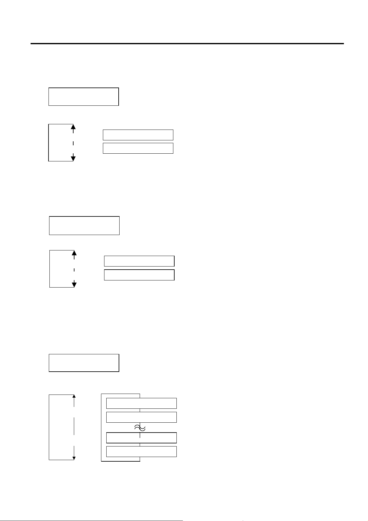
Hold both keys until “<1>DIAG. Vx.x” message appears on the display.
<1>DIAG. Vx.x
[FEED]
[RESTART]
[PAUSE]
This is the start of the Self-Diagnostic Test
menu. → Section 2.1
<2>PARAMETER SET
[PAUSE]
[FEED]
<3>ADJUST SET
[FEED]
<4>TEST PRINT
[FEED]
<5>SENSOR ADJ.
[RESTART]
[PAUSE]
[RESTART]
[PAUSE]
[RESTART]
[PAUSE]
[FEED]
<6>RAM CLEAR
[RESTART]
[PAUSE]
[FEED]
<7>IP ADDRESS
[FEED]
[RESTART]
[PAUSE]
[RESTART]
This is the start of the Parameter Setting
menu. → Section 2.2
This is the start of the Printer Parameter Fine
djustment menu. → Section 2.3
This is the start of the Test Print menu.
→ Section 2.4
This is the start of the Sensor Adjustment
menu. → Section 2.5
This is the start of the RAM Clear menu.
→ Section 2.6
This is the start of the IP Address Setting
menu. → Section 2.7
Continued on the next page.
2- 1
Page 8

2. SYSTEM MODE EO13-33002
(Revision Date: Jul. 24, 2008)
2. SYSTEM MODE
Continued from the previous page.
<8>BASIC
[FEED]
<9>FOR FACTORY
[RESTART]
[PAUSE]
[PAUSE]
This is the start of the Basic Setting menu.
→ Section 2.8
This is the start of the Factory Mode menu.
[FEED]
<10>RFID
[FEED]
[RESTART]
[PAUSE]
This is the RFID Module Setting menu.
→ Section 2.9
NOTES: 1. System Mode menu can be selected with the [RESTART] or [FEED] key.
2. Pressing the [PAUSE] key allows you to enter the sub menus of each System Mode menu.
Flowcharts of each menu’s sub menus are provided on the following pages.
3. “x.x” of “DIAG. Vx.x” indicates firmware version and revision.
2- 2
Page 9

2. SYSTEM MODE EO13-33002
2.1 Self-diagnostic Test
2.1 Self-diagnostic Test
Outline of Self-diagnostic Test
In the Self-diagnostic test mode, the printer automatically checks and prints out the printer system
information such as the sensor status or interface, and the maintenance counter. Also it performs a print
head broken element check.
The Self-diagnostic test contains the following sub menus:
NOTE: Use the [FEED] or [RESTART] key to select a desired option.
How to Enter Self-diagnostic Test Mode
Turn on the printer while pressing the [FEED] and [PAUSE] keys at the same time. Hold both keys until the
“<1>DIAG. Vx.x” message appears in the display.
<1>DIAG. Vx.x
[PAUSE]
<1>DIAG. Vx.x
PRT TYPE TRANSFR
[PAUSE]
<1>DIAG. Vx.x
TYPE[S] NO CUT
[PAUSE]
<1>DIAG. Vx.x
MAINTENANCE CONT.
[FEED]
<1>DIAG. Vx.x
AUTO DIAGNOSTIC
[FEED]
<1>DIAG. Vx.x
HEAD CHECK
[FEED]
<1>DIAG. Vx.x
[RESTART]
[RESTART]
[RESTART]
[PAUSE]
[PAUSE]
[PAUSE]
Selection of the printing mode.
Selection of the dispensing mode.
Prints out the Maintenance Counter /Parameter Settings.
Performs a Self-Diagnostic Test, and prints out the result.
Checks to see if there is any problem with the print head.
2- 3
Page 10

2. SYSTEM MODE EO13-33002
2.1 Self-diagnostic Test
2.1.1 Printing Mode Selection
While “PRT TYPE TRANSFR” is displayed on the LCD, press the [PAUSE] key. The type of printing mode
can be selected:
“TRANSFR” (Thermal transfer) or “DIRECT” (Thermal direct).
After selecting the printing mode to be used, press the [PAUSE] key.
[RESTART]
NOTE: When using the ribbon, be sure to select “Thermal Transfer”. When using the thermal media, be sure to
[FEED]
select the “Thermal Direct”.
<1>DIAG. Vx.x
PRT TYPE TRANSFR
<1>DIAG. Vx.x
PRT TYPE NO TRAN
<1>DIAG. Vx.x
PRT TYPE DIRECT
Thermal transfer: When transparent ribbon is used.
Thermal transfer: When non-transparent ribbon is used.
Thermal direct: When thermal paper is used.
2.1.2 Dispensing Mode Selection
When “TYPE[S] NO CUT” is displayed, press the [PAUSE] key. The type of dispensing mode can be
selected:
“[S] NO CUT” (Batch issue) or “[C] WITH CUT” (Cut issue)
After selecting the dispensing mode to be used, press the [PAUSE] key.
[RESTART]
NOTE: When using the cutter module, be sure to select “[C] WITH CUT”. When the cutter module is not
installed, be sure to select “[S] NO CUT”.
[FEED]
<1>DIAG. Vx.x
TYPE[S] NO CUT
<1>DIAG. Vx.x
TYPE[C] WITH CUT
[S] NO CUT (Batch issue): To issue media in batch
mode.
[C] WITH CUT (Cut issue): When an optional cutter
module is installed.
2- 4
Page 11

2. SYSTEM MODE EO13-33002
A
A
2.1 Self-diagnostic Test
2.1.3 Maintenance Counter/Parameter Settings Print Out
When “MAINTENANCE CONT” is displayed, the printer is ready to print out the Maintenance
Counter/Parameter Settings. Press the [PAUSE] key to start.
<1>DIAG. Vx.x
MAINTENANCE CONT
• Print Sample
[PAUSE]
(1)
TOTAL FEED 1.1km [QM]
(2)
FEED 1.1km
(3)
PRINT 0.5km
(4)
CUT 96
(5)
HEAD U/D 12320
(6)
RIBBON 3h
(7)
SOLENOID 2h
(8)
232C ERR 255
(9)
SYSTEM ERR 0
(10)
POWER FAIL 0
[PC] [KEY]
(11)
FEED +2.0mm FEED +0.0mm
(12)
CUT +0.0mm CUT +1.0mm
(13)
BACK +0.0mm BACK +0.0mm
(14)
TONE(T) +0 step TONE(T) +0 step
(15)
TONE (D) +0 step TONE(D) +0 step
(16)
RBN(FW) -10 RBN (FW) -8
(17)
RBN (BK) +0 RBN (BK) +0
(18)
X ADJ. +0.0mm
(19)
THRESHOLD (R) 1.0V
(20)
THRESHOLD (T) 1.4V
(21)
FONT [PC-850] [0]
(22)
SPEED [9600]
(23)
DATA LENG. [8]
(24)
STOP BIT [1]
(25)
PARITY [EVEN]
(26)
CONTROL [XON+READY AUTO]
(27)
MESSAGE [ENGLISH]
(28)
FORWARD WAIT [ON] +0.0mm
(29)
HEAD UP CUT [ON]
(30)
RIBBON SAVE [ON:LABEL]
(31)
CODE [AUTO]
(32)
RIBBON [TRANS]
(33)
PEEL OFF STATUS [ON]
(34)
FEED KEY [FEED]
(35)
KANJI [TYPE1]
(36)
EURO CODE [B0]
(37)
(38)
(39)
(40)
(41)
(42)
(43)
(44)
(45)
(46)
(47)
(48)
UTO HD CHK [OFF]
CK/BUSY [TYPE1]
WEB PRINTER [OFF]
SENSOR POSITION [CENTER]
INPUT PRIME [ON]
EX. I/O MODE [TYPE1]
PLUG & PLAY [OFF]
LBL/RBN END [TYPE1]
PRE PEEL OFF [ON] +0.0mm
BACK SPEED [STD]
MAXI CODE SPEC. [TYPE1]
PEEL OFF TRQ [R3]
------------------------------------------------------------------------------
<1>DIAG. Vx.x
CHECKING & PRINT
<1>DIAG. Vx.x
2- 5
Page 12

2. SYSTEM MODE EO13-33002
A
(Revision Date: Jul. 24, 2008)
2.1 Self-diagnostic Test
-------------------------------------------------------------------------------
(49)
STABILIZER [ON]
(50)
(51)
(52)
(53)
(54)
(55)
(56)
(57)
(58)
(59)
(60)
(61)
(62)
(63)
(64)
(65)
(66)
(67)
(68)
(69)
(70)
(71)
(72)
(73)
(74)
(75)
(76)
(77)
(78)
(79)
(80)
(81)
UTO CALIB. [OFF]
LAN [ON SNMP ON]
PRTR IP ADDRESS [192.168.010.020]
GATE IP ADDRESS [000.000.000.000]
SUBNET MASK [255.255.255.000]
MAC ADDRESS [00-80-91-34-00-CC]
TTF AREA [1280KB]
EXT CHR AREA [ 256KB]
BASIC AREA [ 128KB]
PC SAVE AREA [ 128KB]
SOCKET PORT [OFF][08000]
BASIC [OFF]
BASIC TRACE [OFF]
DHCP [OFF]
DHCP ID [FFFFFFFFFFFFFFFFFFFF]
[FFFFFFFFFFFF]
DHCP HOST NAME [ ]
RTC BATT. CHK [ON]
RTC RENEWAL [PAGE]
RFID MODULE [U2]
RFID TAG TYPE [NONE ]
RFID ERR CHECK [OFF]
RFID RETRY [ 3]
RFID RD CYCLE [ 5] [2.0sec]
RFID WT CYCLE [ 5] [2.0sec]
RFID ADJ RETRY [+00mm]
RFID POWER LEV [ 18]
RFID AGC THR. [0]
RFID Q VAL [0]
RFID WT AGC [ 0]
RFID WT AGC MIN [ 0]
RFID WT OK TAGS 0
RFID VOID PRINT TAGS 0
NOTE: Print conditions:
Print speed: 4”/sec., Sensor: No sensor, Printing mode: Thermal transfer/Direct thermal
length: 240 mm, Issue mode: Batch printing
(*1) Depends on the printing mode setting.
(*1)
, Media
2- 6
Page 13

2. SYSTEM MODE EO13-33002
(Revision Date: Jul. 24, 2008)
2.1 Self-diagnostic Test
• Descriptions of the Maintenance Counter
# Item Count Condition Range
(1) Total media distance
covered
(2) Media distance
covered
(3) Print distance Counts while printing. (Reverse feed is not counted.) See NOTE 3. 0.0 to 200.0 km
(4) Cut count Counts every cut. See NOTE 4. 0 to 1000000 times
(5) Head up and down
cycle count
(6) Ribbon motor driving
time
(7) Solenoid drive time for
head up
(8) RS-232C hardware
error count
(9) System error count Counts when a system error occurs. 0 to 15 times
(10) Momentary power
failure count
(80) Number of successful
RFID write
(81) Number of failure in
RFID write
Counts when the feed motor is driven to feed, print or issue media.
(Counted also during a reverse feed.) See NOTE 2.
Destination printed on the same line indicates one selected for a
parameter clear.
Counts every head up and down cycle by means of the solenoid which
is used for the ribbon save function. See NOTE 4.
Counts when the ribbon motor is driven to feed, print or issue media.
(The driving time is also counted during a reverse feed.) See NOTE 5.
Counts when the ribbon save function is activated. See NOTE 5. 0 to 1000 hours
Counts when a parity, overrun or framing error occurs. See NOTE 6. 0 to 255 times
Counts when a momentary power interruption occurs. 0 to 15 times
Counts when an RFID write has succeeded. 0 to 9999999 times
Counts when an RFID write has failed. 0 to 9999999 times
0.0 to 3200.0 km
0.0 to 3200.0 km
0 to 2000000 times
0 to 2000 hours
NOTES:
1. Item from (2) through (10) are initialized to “0” after RAM clear.
2. If the media distance covered is 50.0 cm or less, it is rounded down and no data is added to the memory at power off.
3. If the print distance is 5.5 m or less, it is rounded down and no data is added to the memory at power off.
4. If the count is 31 or less, it is rounded down and no data is added to the memory at power off.
5. If the driving time is 27 sec. or less, it is rounded down and no data is added to the memory at power off.
6. When a sent command results in an error, the same number as the data capacity of the command is counted by byte.
2- 7
Page 14

2. SYSTEM MODE EO13-33002
(Revision Date: Mar. 26, 2009)
2.1 Self-diagnostic Test
• Descriptions of the Parameters
Item # Description Specification
FEED (11) Print start position fine adjustment (PC), (KEY) -50.0 mm to +50.0 mm
CUT (12) Cut/strip position fine adjustment (PC), (KEY) -50.0 mm to +50.0 mm
BACK (13) Reverse feed amount fine adjustment (PC), (KEY) -9.9 mm to +9.9 mm
TONE(T) (14) Print tone fine adjustment (Thermal transfer), (PC), (KEY) -10 step to +10 step
TONE(D) (15) Print tone fine adjustment (Thermal direct), (PC), (KEY) -10 step to +10 step
RBN(FW) (16) Ribbon take-up motor driving voltage fine adjustment
(PC), (KEY)
RBN(BK) (17) Ribbon feed motor driving voltage fine adjustment (PC),
(KEY)
X ADJ. (18) X coordinate fine adjustment -99.9 mm to +99.9 mm
THRESHOLD<R> (19) Threshold manual fine adjustment for the black mark
sensor
THRESHOLD<T> (20) Threshold manual fine adjustment for the feed gap sensor 0.0V to 4.0V
FONT (21)
SPEED (22) Baud rate 2400: 2400 bps 19200: 19200 bps
DATA LENG. (23) Data length 7: 7 bits
STOP BIT (24) Stop bit length selection 1: 1 bit
PARITY (25) Parity NON: None
CONTROL (26) Flow control code XON/XOFF: XON/XOFF
MESSAGE (27) Language selection for LCD message ENGLISH: English
FORWARD WAIT (28) Auto forward wait ON: Available
HEAD UP CUT (29) Head up cut in cut issue mode ON: Activated
RIBBON SAVE (30) Ribbon saving function ON(TAG): Activated
CODE (31) Control code selection AUTO: Automatic selection
Character code PC-850 PC-851 PC-1252 LATIN9 PC-852
Character “0” 0: without slash
-15 step to +0 step
-15 step to +10 step
0.0V to 4.0V
PC-855 PC-1253 Arabic PC-857 PC-1250
PC-1254 PC-8 PC-1251 PC-1257 PC-866
UTF-8
0: with slash
4800: 4800 bps 38400: 38400 bps
9600: 9600 bps 115200: 115200 bps
8: 8 bits
2: 2 bits
ODD: ODD
EVEN: EVEN
READY/BUSY: READY/BUSY (DTR)
XON+READ AUTO:
XON/XOFF+READY/BUSY (DTR)
XON/XOFF AUTO: XON/XOFF
READY/BUSY RTS: RTS
GERMAN: German
FRENCH: French
DUTCH: Dutch
SPANISH: Spanish
JAPANESE: Japanese
ITALIAN: Italian
OFF: Unavailable
NOTE: The stop position fine adjustment
value is also printed out.
OFF: Not activated
(When the head lever is set to
the tag position.)
ON(LBL): Activated
(When the head lever is set to
the label position.)
OFF: Not activated
ESC LF NUL: ESC LF NUL mode
{ | }: Mainframe mode
xx xx xx: Optional code
(The values are given in HEX.)
2- 8
Page 15

2. SYSTEM MODE EO13-33002
(Revision Date: Mar. 26, 2009)
2.1 Self-diagnostic Test
Item # Description Specification
RIBBON (32) Ribbon type selection TRANS: Transparent ribbon
NON TRANS: Non transparent ribbon
PEEL OFF STATUS (33) Strip wait status selection ON: Available
OFF: Unavailable
FEED KEY (34) Feed key function FEED: Feeds one label
PRINT: Prints image buffer on one label
KANJI (35) Kanji code type (Not supported by QM model) TYPE 1: Windows code
TYPE 2: Original code
EURO CODE (36) Euro font code 20H to FFH
AUTO HD CHK (37) Auto print head broken element check ON: Available
OFF: Unavailable
ACK/BUSY (38) Centronics interface ACK/BUSY timing setting TYPE1: A rise of ACK signal and a release
of BUSY occur at the same time.
TYPE2: A fall of ACK signal and a release
of BUSY occur at the same time.
WEB PRINTER (39) Web printer function ON: Available
OFF: Unavailable
SENS POSI (40) Media sensor CENTER: Fixed sensor
EDGE: Movable sensor
INPUT PRIME (41) Input prime selection
(Reset operation when INIT signal is ON)
EX. I/O MODE (42) Expansion I/O interface operating mode TYPE1: Standard mode
PLUG&PLAY (43) Plug & Play setting ON: Available
LBL/RBN END (44) Print processing setting at the label/ribbon error detection TYP1: Printing is paused in the middle of
PRE PEEL OFF (45) Pre-Strip setting OFF: Unavailable
BACK SPEED (46) Reverse Feed Speed setting STD: 3”/second
MAXI CODE SPEC. (47) MAXI code specification selection TYPE1: Compatible with the current
PEEL OFF TRQ (48) Strip motor torque R0: Standard
STABILIZER (49) Stabilizer function ON: Stabilizer function is used.
AUTO CALB. (50) Automatic calibration OFF: Disabled
LAN (51) Enabling or disabling the LAN ON SNMP ON: LAN Enabled
PRTR IP ADDRESS (52) Printer IP address ***.***.***.***
GATE IP ADDRESS (53) Gateway IP address ***.***.***.***
SUBNET MASK (54) Subnet mask ***.***.***.***
MAC ADDRESS (55) MAC (Media Access Control) address for LAN controller
on the MAIN PC Board
TTF AREA (56) True type font registration area size 0 KB to 3072 KB (unit of 128 KB)
EXT CHR AREA (57) External character registration area size 0 KB to 3072 KB (unit of 128 KB)
BASIC AREA (58) BASIC file store area size 0 KB to 1792 KB (unit of 128 KB)
PC SAVE (59) PC saving area size 0 KB to 3072 KB (unit of 128 KB)
SOCKET PORT (60) Socket port number ON: Available
ON: Available
OFF: Unavailable
TYPE2: Inline mode
OFF: Unavailable
printing.
TYP2: Printing is paused after the label is
issued.
LOW: 2”/second
version
TYPE2: Special specification
OFF: Stabilizer function is not used.
ON TRANS: Enabled with the transmissive
sensor
ON REFLECT: Enabled with the reflective
sensor
SNMP Enabled
ON SNMP OFF: LAN Enabled
SNMP Disabled
OFF: LAN Disabled
¶¶-¶¶-¶¶-¶¶-¶¶-¶¶
OFF: Unavailable
Port No. 0 to 65535
2- 9
Page 16

2. SYSTEM MODE EO13-33002
(Revision Date: Mar. 26, 2009)
2.1 Self-diagnostic Test
Item # Description Specification
BASIC (61) BASIC interpreter setting ON: Available
OFF: Unavailable
BASIC TRACE (62) BASIC interpreter trace setting ON: Available
OFF: Unavailable
DHCP (63) DHCP function setting ON: Available
OFF: Unavailable
DHCP ID (64) DHCP ID setting Max. 16 characters
DHCP HOST NAME (65) DHCP host name Max. 16 characters
RTC BATT. CHK (66) RTC Low Battery Check setting ON: Available
OFF: Unavailable
RTC RENEWAL (67) RTC data renewal timing BATCH: per batch
PAGE: per page
RFID MODULE (68) RFID module type NONE: No RFID kit is installed.
U2: U2 B-SX708-RFID-U2-EU-R,
B-SX708-RFID-U2-CN-R
RFID TAG TYPE (69) RFID tag type NONE: 11
EPC C1 Gen2: 24
RFID ERR CHECK (70) RFID error tag detection ON: An error tag detection is performed.
OFF: An error tag detection is not
performed.
RFID RETRY (71) Maximum number of RFID issue retries 0 to 255
RFID RD CYCLE (72)
RFID WT CYCLE (73)
RFID ADJ RETRY (74) RFID adjustment for retry -99 mm to +99 mm
RFID POWER LEV (75) RFID wireless power level setting 9 to 18
RFID AGC THR. (76) RFID AGC Threshold Setting 0 to 15
RFID Q VAL (77) RFID Q VAL (Q value) 0 to 5
RFID WT AGC (78) RFID WT AGC (AGC threshold for data write) 0 to 15
RFID WT AGC MIN (79) RFID WT MIN AGC (AGC threshold lower limit for retry) 0 to 15
Maximum number of RFID read retries
RFID read retry time-out
Maximum number of RFID write retries
RFID write retry time-out
0 to 255
0 sec. to 9.9 sec.
0 to 255
0 sec. to 9.9 sec.
2- 10
Page 17

2. SYSTEM MODE EO13-33002
(Revision Date: Jul. 24, 2008)
2.1 Self-diagnostic Test
2.1.4 Self-Diagnostic Test and Result Print Out
When the Maintenance Counter/Parameter Settings is printed, the message returns to “<1>DIAG. Vx.x”.
Press the [PAUSE] key twice.
The Self-Diagnostic Test is ready. Press the [PAUSE] key to start.
The printer starts a self-diagnosis, and prints out the result. During printing, the message below appears on
the display.
After printing is completed, the display returns to “<1>DIAG. Vx.x”.
NOTE: If an error occurs, an error message appears, the printer stops printing. After clearing the error, press the
• Print Sample
<1>DIAG. Vx.x
AUTO DIAGNOSTIC
<1>DIAG. Vx.x
CHECKING & PRINT
[PAUSE] key to return the display to “<1>DIAG.Vx.x”. The printer does not restart printing automatically.
PROGRAM B-SX8T
(1)
MAIN 15OCT2005 V1.0A: 1A00
BOOT 20SEP2005 V1.0: 8500
FONT AD00
(2)
KANJI GOTHIC :9F00
(3)
MINCHO :7400
EEPROM OK
(4)
SDRAM 16MB
(5)
SENSOR1 00000000, 00000111
(6)
SENSOR2 [H]23°C [A]22°C
(7)
[R]4.2V [T]2.5V
PE LV. [R]1.2V [T]4.3V
(8)
M THRE. [R]5.0V [T]5.0V
(9)
[RANK]1 305DPI
EXP.I/O NG
(10)
EX.232C NG
(11)
SIO NG NG
(12)
STRIP NG
(13)
RFID OK #00RV972 (EU0)
(14)
NOTES: 1. Print conditions: Print speed: 4”/sec., Sensor: No sensor, Printing method: Thermal transfer/Direct
(*1) Depends on the printing mode setting.
2. Software version No., Part No. of ROM and checksum vary according to the
software version of PROGRAM ROM.
3. The last two digits of the checksum are usually “00”.
4. When Kanji ROM is not installed, the checksum becomes “0000”.
5. The symbol “°” of “°C” may not be printed depending on the type of character code.
thermal
(*1)
, Media length: 87 mm, Issue mode: Batch printing
2-11
Page 18

2. SYSTEM MODE EO13-33002
2.1 Self-diagnostic Test
• Descriptions
(1) Program ROM Check (Model Name, Date, Version, Part number, Checksum)
PROGRAM B-SX8T
Program area
Model name
MAIN
Main area
Creation date
Software version No.
BOOT
Boot area
Creation date
Software version No.
(2) Alphanumeric Font ROM Check
FONT 5600
Font area
(3) Kanji ROM Check
15OCT2002 V1.0 A : 1A00
Checksum
Revision No.: Space or A to Z
20SEP2002 V1.0: 8500
Checksum
Checksum of Font area
KANJI NONE : 0000
Kanji area
NONE: Kanji ROM is not installed.
GOTHIC: Gothic bit map Kanji ROM is installed.
NONE
: 0000
NONE: Kanji ROM is not installed.
MINCHO: Mincho bit map Kanji ROM is installed.
CHINESE: Chinese character bit map Kanji ROM is installed.
(4) EEPROM Check
EEPROM OK
EEPROM (Backup Memory)
OK: Data in the check area can be properly read/written.
NG (No good): Data in the check area cannot be properly read/written.
Checksum
Checksum
2-12
Page 19

2. SYSTEM MODE EO13-33002
2.1 Self-diagnostic Test
(5) SDRAM Capacity
SDRAM 16MB
System/drawing memory
Capacity of DRAM
(6) Sensor 1 Check
The status of the Strip Sensor, Ribbon Feed Motor Sensor, Ribbon Take-up Motor Sensor, Cutter
Home Position Switch, Head Up Sensor, and Pinch Roller Sensor are printed.
SENSOR1 00000000, 0 1 1 1 0 0 1 1
Fixed to 0.
Pinch roller sensor status
1: The pinch roller is closed.
NOTE: If either the pinch roller or the print head
is opened, printing is not performed.
Head up sensor status
1: The print head is closed.
NOTE: If either the pinch roller or the print head
is opened, printing is not performed.
Cutter home position sensor status
0: Home position
1: Other position
Fixed to 0.
Ribbon take-up motor sensor status
0: The detecting point is positioned outside the slit.
1: The detecting point is positioned inside the slit.
Ribbon feed motor sensor status
0: The detecting point is positioned outside the slit.
1: The detecting point is positioned inside the slit.
Fixed to 0.
Strip sensor status
0: The label is not detected.
1: The label is detected.
Sensor/Switch Print status description
Pinch roller sensor Detects the Open or Close status of the pinch roller. Only when
the pinch roller and the print head are both closed, printing is
performed.
Head up sensor Detects the Open or Close status of the print head. Only when
the pinch roller and the print head are both closed, printing is
performed.
Cutter home position sensor Indicates whether or not the cutter is at the home position.
Ribbon take-up motor sensor
Ribbon feed motor sensor
Controls ribbon motor rotation by detecting the slit on the ribbon
take-up motor and the ribbon feed motor. Indicates the position
of the slit sensor.
Strip sensor Detects whether or not the label is at the paper outlet in strip
printing mode. When the label is not detected, the printer feeds
the label at the print start position.
2-13
Page 20

2. SYSTEM MODE EO13-33002
2.1 Self-diagnostic Test
(7) Sensor 2 Check
The status of the Print Head Thermistor, Ambient Temperature Thermistor, Black Mark Sensor, and
Feed Gap Sensor, Print Head resistance rank, and print head resolution are printed.
SENSOR2 [H]23°C [A]22°C [R]4.2V [T]2.5V
Ambient temperature thermistor status:
0°C to 86°C
If it is undetectable, “--°C “ is printed.
Black mark sensor status:
0.0 to 5.0V
Feed gap sensor status:
0.0 to 5.0V
Print head thermistor status:
0°C to 86°C
Sensor/Thermistor Print status description
Print head thermistor A thermistor built in the print head detects a print head
temperature. The current supplied to the print head (= print tone)
is controlled on the basis of this temperature.
When the print head overheats (80°C or over), the printer
displays “EXCESS HEAT TEMP” message and stops printing to
protect the print head.
Ambient temperature thermistor Temperature inside the printer (around the media) is detected.
The current supplied to the print head (= print tone) is controlled
on the basis of this temperature. When the temperature of 61°C
is detected, an error message, “EXCESS HEAT TEMP”, is
displayed and the printer stops.
Black mark sensor Real time voltage detected by the black mark sensor is
displayed/printed.
Feed gap sensor Real time voltage detected by the feed gap sensor is
displayed/printed.
Print head resistance rank There is individual variability in average resistance of the thermal
element. The current supplied to the print head is controlled on
the basis of this value to obtain the optimal print tone.
(8) Paper End Level Check
PE LV. [R]1.2V [T]4.3V
Paper End Level
Reflective sensor no paper level:
0.0 to 5.0 V
2-14
Transmissive sensor no paper level:
0.0 to 5.0 V
Page 21

2. SYSTEM MODE EO13-33002
2.1 Self-diagnostic Test
(9) Manual Threshold Check
M THRE. [R]5.0V [T]5.0V [RANK]1 305DPI
Thermal head resistance rank:
(See the table below.)
Resolution of head installed
Manual Threshold Check
Reflective sensor manual threshold level:
0.0 to 5.0 V
Transmissive sensor manual threshold level:
0.0 to 5.0 V
Resistance
rank
Average resistance
(ohm)
Resistance
rank
Average resistance
(ohm)
0 1432 to 1454 8 1242 to 1265
1 1409 to 1431 9 1219 to 1241
2 1385 to 1408 10 1195 to 1218
3 1361 to 1384 11 1171 to 1194
4 1337 to 1360 12 1147 to 1170
5 1314 to 1336 13 1124 to 1146
6 1290 to 1313 14 1100 to 1123
7 1266 to 1289 15 1076 to 1099
(10) Expansion I/O Interface Check
Result of a loop back check performed on an expansion I/O interface, which may connect to an
external equipment like a labeller, is printed.
EXP.I/O OK
Expansion I/O PC board
Loopback test
OK: The circuit has no problem.
NG (Not good): The circuit has a problem or loopback jig is not
attached.
Connect the jig like below to the Expansion I/O PC board’s connector and perform a loop back check.
R
R
R
R
R
R
12111098764 531 2
2423222120191816 171513 14
Vcc
GND
LED
R
R = 300 ohms
Connector: FCN-781P024-G/P
2-15
Page 22

2. SYSTEM MODE EO13-33002
j
(Revision Date: Jul. 24, 2008)
2.1 Self-diagnostic Test
(11) Internal Serial Interface Check
EX.232C NG
OK: The circuit has no problem.
NG (Not good): The circuit has a problem or loopback jig is not
attached.
Internal Serial Interface
Connect the jig like below to the serial interface connector and perform a loop back check.
(12) SIO Interface check
Result of optional serial interface check is printed.
SIO NG NG
DIN OK: The circuit has no problem.
NG (Not good): The circuit has a problem or loopback jig
is not attached.
DSUB OK: The circuit has no problem.
NG (Not good): The circuit has a problem or loopback jig is not
attached.
Optional Serial Interface
(13) Strip sensor check
Result of a check of the strip sensor on optional strip module is printed.
STRIP
NG
OK: No problem
NG (Not good): There is a problem or a jig is not attached.
Strip sensor
(14) RFID module check
Results of a RFID module check is printed.
RFID
OK #00RV972 (EU0)
Destination EU0: Europe
RFID module version (Printed only when the result is OK.)
OK: The RFID module has no problem.
NG (No good): The RFID module has a problem or loop back
ig is not attached.
RFID module
2-16
Page 23

2. SYSTEM MODE EO13-33002
2.1 Self-diagnostic Test
2.1.5 Print Head Element Check
This function is used to check for any broken thermal elements of the print head.
If blurred print or missing dots occurs, this check helps you find whether the thermal elements are actually
broken or the print head is just stained.
Also, use this check just after a replacement of a print head to find an initial failure.
When the Self-Diagnostic Test result is printed, the message returns to “<1>DIAG. Vx.x”. Press the
[PAUSE] key three times and [FEED] key twice.
The printer is ready to check the print head to see if there is any problem with the print head. Press the
[PAUSE] key to start.
If there is no problem with the print head, the print head check is complete. Press the [PAUSE] key to
return to “<1>DIAG. Vx.x”.
If there is a problem with the print head, the following message is displayed.
Press the [PAUSE] key to return to “<1>DIAG. Vx.x”.
NOTES: 1. Make sure that the Top Cover is closed before starting the print head check.
2. If “HEAD ERROR” appears, the print head element may be damaged. Replace the print head.
3. The print head element check can be performed at the power on time.
For selecting this function, refer to Section 2.2 Parameter Setting.
<1>DIAG. Vx.x
HEAD CHECK
<1>DIAG. Vx.x
NORMAL END
<1>DIAG. Vx.x
HEAD ERROR
[PAUSE]
<1>DIAG. Vx.x
CHECKING
2-17
Page 24

2. SYSTEM MODE EO13-33002
A
[
[
[
[
[
[
[
A
A
A
[
]
[
]
[
]
[
]
[
]
[
]
[
]
[
]
[
]
[
]
[
]
[
]
p
[
[
[
]
[
]
2.2 Parameter Setting
2.2 Parameter Setting
Outline of Parameter Setting
In the Parameter Setting mode, various kinds of parameters, such as communication, key, LCD, etc. can be set.
This will allow a use of the printer to comply with your operating conditions.
The Parameter Setting menu contains the following:
<2>PARAMETER SET
<2>PARAMETER SET
FONT CODE PC-850
<2>PARAMETER SET
ZERO FONT 0
<2>PARAMETER SET
SPEED 9600bps
<2>PARAMETER SET
DATA LENG. 8bits
<2>PARAMETER SET
STOP BIT 1bit
<2>PARAMETER SET
PARITY EVEN
<2>PARAMETER SET
XON+READY AUTO
<2>PARAMETER SET
LCD ENGLISH
<2>PARAMETER SET
FORWARD WAIT OFF
<2>PARAMETER SET
HEAD UP CUT OFF
<2>PARAMETER SET
RBN SAVE ON (TAG)
<2>PARAMETER SET
CODE ESC,LF,NUL
<2>PARAMETER SET
RIBBON NON TRANS
<2>PARAMETER SET
PEEL OFF STS OFF
PAUSE]
PAUSE]
PAUSE]
[PAUSE]
PAUSE]
[PAUSE]
[PAUSE]
PAUSE]
PAUSE]
PAUSE]
PAUSE]
PAUSE]
[PAUSE]
[PAUSE]
[PAUSE]
Character code selection
Character zero selection
Baud rate selection
Data length selection
Stop bit length selection
Parity selection
Flow control code selection
LCD language selection
uto forward wait selection
Head up cut selection
Ribbon save function selection
Control code selection
Ribbon type selection
Strip wait status selection
<2>PARAMETER SET
FEED KEY FEED
[PAUSE]
<2>PARAMETER SET
KANJI CODE TYPE1
[PAUSE]
<2>PARAMETER SET
EURO CODE B0
PAUSE
<2>PARAMETER SET
UTO HD CHK OFF
PAUSE
<2>PARAMETER SET
CK/BUSY TYPE1
PAUSE
<2>PARAMETER SET
WEB PRINTER OFF
PAUSE
<2>PARAMETER SET
SENS POSI CENTER
PAUSE
<2>PARAMETER SET
INPUT PRIME OFF
PAUSE
<2>PARAMETER SET
EX.I/O TYPE1
PAUSE
<2>PARAMETER SET
PLUG & PLAY OFF
PAUSE
<2>PARAMETER SET
LBL/RBN END TYPE1
PAUSE
<2>PARAMETER SET
PRE PEEL OFF OFF
PAUSE
<2>PARAMETER SET
BACK SPEED STD
PAUSE
<2>PARAMETER SET
MAXI CODE TYPE1
PAUSE
<2>PARAMETER SET
PEEL OFF TRQ R0
PAUSE
<2>PARAMETER SET
STABILIZER ON
PAUSE
Feed key function selection
Kanji code selection
Euro code selection
uto print head check selection
Centronics ACK/BUSY timing
selection
Web printer function selection
Media sensor selection
Input prime selection
Expansion I/O interface type
selection
Plug & Play selection
Label end/Ribbon end selection
Pre-strip selection
Reverse feed speed selection
Maxi code specification selection
motor torque selection
Stri
Stabilizer function selection
NOTE: Baud rate, Data length, Parity, and Transmission control code should be set to the same values as those of the host
computer. Failure to do this causes improper operation.
2-18
Page 25

2. SYSTEM MODE EO13-33002
2.2 Parameter Setting
How to Enter Parameter Setting Mode
Turn on the printer while pressing the [FEED] and the [PAUSE] keys at the same time. Hold both keys
until the “<1>DIAG. Vx.x” message appears.
<1>DIAG. Vx.x
Press the [FEED] key. The printer is at the start of the Parameter Setting menu.
<2>PARAMETER SET
2.2.1 Character Code Selection
This parameter is to choose a character code used for printing. Printed characters differ depending on a
chosen character code and font. For details of characters, refer to the B-SX6T/SX8T Series External
Equipment Interface Specification (Printer Command Manual).
When “<2>PARAMETER SET” appears, press the [PAUSE] key.
<2>PARAMETER SET
FONT CODE PC-850
Use the [FEED] or [RESTART] key to select a desired option.
[RESTART]
[FEED]
After selecting a character code, press the [PAUSE] key.
NOTES: 1. When pressing the [FEED] and [RESTART] keys at the same time in the parameter setting, the
message returns to “<2>PARAMETER SET”.
2. If holding the [FEED] or [RESTART] key for 0.5 seconds or longer in the parameter setting the key
is entered continuously.
3. A changed parameter becomes effective by pressing the [PAUSE].
FONT CODE PC-8
FONT CODE PC-857
FONT CODE PC-852
FONT CODE PC-850
FONT CODE Arabic
FONT CODE LATIN9
FONT CODE PC1257
FONT CODE PC1254
FONT CODE PC1253
FONT CODE PC1252
FONT CODE PC1251
FONT CODE PC1250
FONT CODE PC-850
FONT CODE PC-851
FONT CODE PC-866
FONT CODE UTF-8
2-19
Page 26

2. SYSTEM MODE EO13-33002
2.2 Parameter Setting
2.2.2 Character Zero Selection
This parameter is to choose the way to indicate zero between “0” and “Ø”.
When “<2>PARAMETER SET” appears, press the [PAUSE] key twice.
<2>PARAMETER SET
ZERO FONT 0
Use the [FEED] or [RESTART] key to select a desired option.
After selecting a character zero, press the [PAUSE] key.
NOTE: The following fonts do not support a zero with slash.
Bit Map Font: OCR-A, OCR-B, GOTHIC 725 Black, Kanji, Chinese
Outline Font: Price Font 1, Price Font 2, Price Font 3, DUTCH 801 Bold, BRUSH 738 Regular, GOTHIC
[RESTART]
[FEED]
ZERO FONT 0
ZERO FONT Ø
725 Black, True Type Font
(Without slash)
(With slash)
2.2.3 Baud Rate Selection
This parameter is to choose a baud rate of the RS-232C interface. When the printer communicates with a
host computer by serial interface, be sure to match the setting with the host.
When “<2>PARAMETER SET” appears, press the [PAUSE] key until the following display appears.
<2>PARAMETER SET
SPEED 9600bps
Use the [FEED] or [RESTART] key to select a desired option.
[RESTART]
[FEED]
After selecting a baud rate, press the [PAUSE] key.
SPEED 115200 bps
SPEED 38400 bps
SPEED 19200 bps
SPEED 9600 bps
SPEED 4800 bps
SPEED 2400 bps
2-20
Page 27

2. SYSTEM MODE EO13-33002
2.2 Parameter Setting
2.2.4 Data Length Selection
This parameter is to choose a communication data length of the RS-232C interface.
7 bits is used when transmitting alphanumeric data only. 8 bits is used to when transmitting special
characters. Be sure to match a setting with a host computer.
When “<2>PARAMETER SET” appears, press the [PAUSE] key until the following display appears.
<2>PARAMETER SET
DATA LENG. 8bits
Use the [FEED] or [RESTART] key to select a desired option.
[RESTART]
[FEED]
After selecting a data length, press the [PAUSE] key.
DATA LENG. 8bits
DATA LENG. 7bits
2.2.5 Stop Bit Length Selection
This parameter is to choose a stop bit length of the RS-232C interface.
Be sure to match a setting with a host computer.
When “<2>PARAMETER SET” appears, press the [PAUSE] key until the following display appears.
<2>PARAMETER SET
STOP BIT 1bit
Use the [FEED] or [RESTART] key to select a desired option.
[RESTART]
[FEED]
After selecting a stop bit, press the [PAUSE] key.
STOP BIT 1bit
STOP BIT 2bits
2-21
Page 28

2. SYSTEM MODE EO13-33002
2.2 Parameter Setting
2.2.6 Parity Selection
This parameter is to choose the parity of the RS-232C interface.
When “<2>PARAMETER SET” appears, press the [PAUSE] key until the following display appears.
<2>PARAMETER SET
PARITY NONE
Use the [FEED] or [RESTART] key to select a desired option.
[RESTART]
[FEED]
After selecting the parity, press the [PAUSE] key.
PARITY EVEN
PARITY ODD
PARITY NONE
2.2.7 Flow Control Code Selection
This parameter is to choose a flow control code of the RS-232C interface.
When “<2>PARAMETER SET” appears, press the [PAUSE] key until the following display appears.
<2>PARAMETER SET
XON+READY AUTO
Use the [FEED] or [RESTART] key to select a desired option.
[RESTART]
[FEED]
XON/XOFF AUTO
XON+READY AUTO
READY/BUSY
XON/XOFF
READY/BUSY RTS
After selecting a flow control code, press the [PAUSE] key.
NOTE: The following is the detailed descriptions for each transmission control code.
1) XON/XOFF AUTO
At the power on time, the printer outputs XON. At the power off time, the printer outputs XOFF.
2) XON+READY AUTO
At the power on time, the printer outputs XON. At the power off time, the printer outputs XOFF.
3) READY/BUSY
At the power on time, the DTR signal output from the printer turns to High level (READY). At the
power off time, the printer does not output XOFF.
4) ON/XOFF
At the power on time, the printer outputs XON. At the power off time, the printer does not output
XOFF.
5) READY/BUSY RTS
At the power on time, the RTS signal output from the printer turns to High level (READY). At the
power off time, the printer does not output XOFF.
XON/XOFF mode
XON/XOFF+READY/BUSY (DTR) mode
READY/BUSY (DTR) mode
XON/XOFF mode
RTS mode
2-22
Page 29

2. SYSTEM MODE EO13-33002
2.2 Parameter Setting
2.2.8 LCD Language Selection
This parameter is to choose a language in which the LCD message is displayed.
When “<2>PARAMETER SET” appears, press the [PAUSE] key until the following display appears.
<2>PARAMETER SET
LCD ENGLISH
Use the [FEED] or [RESTART] key to select a desired option.
[RESTART]
[FEED]
ENGLISH
ITALIAN
JAPANESE
SPANISH
DUTCH
FRENCH
GERMAN
After selecting a language, press the [PAUSE] key.
2.2.9 Auto Forward Wait Selection
This parameter is to choose whether to activate the Auto Forward Wait function or not.
This function, used in the cut mode, automatically feeds the media forward for about 14 mm if there is more
than 1-second idle time after printing, to prevent the top edge of the media from curling.
When “<2>PARAMETER SET” appears, press the [PAUSE] key until the following display appears.
<2>PARAMETER SET
FORWARD WAIT OFF
Use the [FEED] or [RESTART] key to select a desired option.
[RESTART]
FORWARD WAIT ON
[FEED]
FORWARD WAIT OFF
When ON is selected, pressing the [PAUSE] key will result that the LCD Message Display shows the stop
position fine adjustment value setting screen.
<2>PARAMETER SET
POSITION +0.0mm
[RESTART]
[FEED]
POSITION +5.0mm
POSITION +0.0mm
POSITION -5.0mm
[FEED] key: Pressing the [FEED] key one time causes a –0.1 mm change, up to –5.0 mm.
[RESTART] key: Pressing the [RESTART] key one time causes a +0.1 mm change, up to +5.0 mm.
Activated
Not activated
After selecting an auto forward wait, press the [PAUSE] key.
2-23
Page 30

2. SYSTEM MODE EO13-33002
2.2 Parameter Setting
NOTES: 1. If the printer is not used for a few days, the top edge of the media may become curly, which may
cause a paper jam. The Auto Forward Wait Function prevents this problem since the media feed
amount is increased so that the media stops past the platen.
2. When the Stop Position Fine Adjustment Value is set in + direction, the media will stop past the
media outlet.
When the value is set in – direction, the media will stop inside the media outlet.
3. This setting will be useful to fine adjust the cut position of labels.
2.2.10 Head Up Cut Selection
This parameter is to choose whether to activate the head up action in the cut issue.
This function prevents ribbon smudges by raising the print head during a reverse feed to the print start
position.
When “<2>PARAMETER SET” appears, press the [PAUSE] key until the following display appears.
<2>PARAMETER SET
HEAD UP CUT OFF
Use the [FEED] or [RESTART] key to select a desired option.
[RESTART]
[FEED]
HEAD UP CUT ON
HEAD UP CUT OFF
After selecting the head up action in cut issue, press the [PAUSE] key.
NOTES: 1. For the B-SX6T, this function is available only when an optional ribbon saving module (B-SX908-R-
QM-R) is installed
2. The print head may not be raised depending on the rise of the solenoid’s temperature.
Activated
Not activated
2.2.11 Ribbon Save Function Selection
This parameter is to choose whether to activate the Ribbon Saving function or not.
This function enables reducing the ribbon loss caused by taking up unused ribbon during non-print areas.
When “<2>PARAMETER SET” appears, press the [PAUSE] key until the following display appears.
<2>PARAMETER SET
RBN SAVE ON (TAG)
Use the [FEED] or [RESTART] key to select a desired option.
[RESTART]
[FEED]
RBN SAVE ON (TAG)
RBN SAVE ON (LBL)
RBN SAVE OFF
After selecting the ribbon save function, press the [PAUSE] key.
NOTES: 1. For the B-SX6T, this function is available only when an optional ribbon saving module (B-SX908-R-
QM-R) is installed.
2. If this parameter is set to ON without installing a ribbon saving module, the ribbon will be slack
during paper feed or printing, and as a result, printing cannot be performed properly.
Also, be sure to conform the choice to the actual head lever position. Failure to do this may disable
proper ribbon saving function.
Activated (When the head lever is set to position 2.)
Activated (When the head lever is set to position 1.)
Not activated
2-24
Page 31

2. SYSTEM MODE EO13-33002
2.2 Parameter Setting
3. The ribbon saving function is activated when there is a 20-mm or more non-print area in the media
feed direction.
4. Ribbon saving is enabled up to 4 areas per media.
5. To use the ribbon saving function for more than one area in a label/tag, there should be at least an
8-mm print area between non-print areas where the ribbon saving is performed
2.2.12 Control Code Selection
This parameter is to choose a Control Code.
When “<2>PARAMETER SET” appears, press the [PAUSE] key until the following display appears.
<2>PARAMETER SET
CODE AUTO
Use the [FEED] or [RESTART] key to select a desired option.
[RESTART]
[FEED]
NOTES: 1. This parameter is used to select the Control Code for the communication between the printer and
the host computer.
2. Selecting “Manual” enables you to set the control code.
When “CODE MANUAL” is selected and the [PAUSE] key is pressed, the LCD display will show the setting
screen of CONTROL CODE1 to CONTROL CODE3 as follows.
<2>PARAMETER SET
CONTROL CODE1 1B
[RESTART]
[FEED]
NOTES: 1. Pressing the [FEED] or [RESTART] key causes 1-byte change in the Control Code value.
2. You cannot specify the same control code with the one used for the commands.
3. You cannot use the specified Control Code for the data of the Data Command or Display Command.
CODE AUTO
CODE ESC,LF,NUL
CODE{|}
CODE MANUAL
CONTROL CODE1 FF
CONTROL CODE1 FE
CONTROL CODE1 FD
CONTROL CODE1 02
CONTROL CODE1 01
CONTROL CODE1 00
Automatic selection
Manual selection
Manual selection
Control codes should be specified.
2-25
Page 32

2. SYSTEM MODE EO13-33002
2.2 Parameter Setting
After setting the control code for Control Code 1, press the [PAUSE] key to show the CONTROL CODE2
screen. In a same manner, press the [PAUSE] key after setting the control code for Control Code 2 to
display the CONTROL CODE3 screen.
CONTROL CODE1
CONTROL CODE2
CONTROL CODE3
[PAUSE]
[PAUSE]
Press the [PAUSE] key after setting the control code for Control Code 3.
2.2.13 Ribbon Type Selection
This parameter is to choose a ribbon type to be used.
When “<2>PARAMETER SET” appears, press the [PAUSE] key until the following display appears.
<2>PARAMETER SET
RIBBON TRANS
Use the [FEED] or [RESTART] key to select a desired option.
[RESTART]
[FEED]
After selecting a ribbon type, press the [PAUSE] key.
RIBBON TRANS
RIBBON NON TRANS
Transparent ribbon
Non transparent ribbon
2.2.14 Strip Wait Status Selection
This parameter is to choose when the printer sends a strip wait status (05H) to a host in response to a
status request command.
When “<2>PARAMETER SET” appears, press the [PAUSE] key until the following display appears.
<2>PARAMETER SET
PEEL OFF STS OFF
Use the [FEED] or [RESTART] key to select a desired option.
[RESTART]
PEEL OFF STS OFF
[FEED]
PEEL OFF STS ON
After selecting the Strip Wait Status, press the [PAUSE] key.
A strip wait status is sent when the printer receives the next
issue command and the previously printed label is waiting to
be removed.
A strip wait status is sent when a printed label is waiting to
be removed.
2-26
Page 33
2. SYSTEM MODE EO13-33002
2.2 Parameter Setting
2.2.15 FEED Key Function Selection
This parameter is to choose the function of the [FEED] key.
When “<2>PARAMETER SET” appears, press the [PAUSE] key until the following display appears.
<2>PARAMETER SET
FEED KEY FEED
Use the [FEED] or [RESTART] key to select a desired option.
[RESTART]
[FEED]
FEED KEY FEED
FEED KEY PRINT
The [FEED] key will feed one media when pressed.
The [FEED] key will print the data in the Image Buffer
(The last printed data)
After selecting the FEED key function, press the [PAUSE] key.
2.2.16 KANJI Code Selection
This parameter is to choose a KANJI code.
When “<2>PARAMETER SET” appears, press the [PAUSE] key until the following display appears.
<2>PARAMETER SET
KANJI CODE TYPE1
Use the [FEED] or [RESTART] key to select a desired option.
[RESTART]
[FEED]
KANJI CODE TYPE1
KANJI CODE TYPE2
NOTE: Kanji code selection is not supported by the QM model as the Kanji ROMs are not installed.
Windows code
Original code
After selecting a Kanji code, press the [PAUSE] key.
2.2.17 EURO Code Selection
This parameter is to choose a Euro code (€).
When “<2>PARAMETER SET” appears, press the [PAUSE] key until the following display appears.
<2>PARAMETER SET
EURO CODE B0
Use the [FEED] or [RESTART] key to select a desired option.
[RESTART]
[FEED]
NOTE: Pressing the [FEED] or [RESTART] key causes 1 byte change in the Euro Code value.
After selecting a Euro code, press the [PAUSE] key.
EURO CODE 20
EURO CODE 21
EURO CODE FE
EURO CODE FF
2-27
Page 34

2. SYSTEM MODE EO13-33002
A
2.2 Parameter Setting
2.2.18 Auto Print Head Check Selection
This parameter is to choose whether to perform the Auto Print Head Check function at the power on time.
When “<2>PARAMETER SET” appears, press the [PAUSE] key until the following display appears.
<2>PARAMETER SET
AUTO HD CHK OFF
Use the [FEED] or [RESTART] key to select a desired option.
NOTES: 1. It will take about 2 seconds to perform an Auto Print Head check.
2. It is recommended that this function should be activated when high quality printing such as bar
3. When a broken element is found, the printer stops, displaying “HEAD ERROR”. The error state can
[RESTART]
[FEED]
codes printing is required. Otherwise, choose OFF.
be cleared by pressing the [RESTART] key, but if the broken element affects bar code readability or
actual operations, please replace the print head with a proper one.
AUTO HD CHK OFF
AUTO HD CHK ON
After selecting auto print head check, press the [PAUSE] key.
Auto print head broken element check is not performed.
Auto print head broken element check is performed.
2.2.19 Centronics Interface ACK/BUSY Timing Selection
This parameter is to choose an ACK/BUSY timing of the Centronics interface.
“TYPE1” has been chosen as default, but if a communication error occurs or a communication is not
properly made, change to “TYPE2”.
When “<2>PARAMETER SET” appears, press the [PAUSE] key until the following display appears.
<2>PARAMETER SET
ACK/BUSY TYPE1
Use the [FEED] or [RESTART] key to select a desired option.
[RESTART]
ACK/BUSY TYPE1
[FEED]
ACK/BUSY TYPE2
After selecting an ACK/BUSY timing, press the [PAUSE] key.
rise of ACK signal and a release of BUSY occur at the same
time.
A fall of ACK signal and a release of BUSY occur at the same
time.
2-28
Page 35

2. SYSTEM MODE EO13-33002
2.2 Parameter Setting
2.2.20 Web Printer Function Selection
This parameter is to choose whether to use the printer as a web printer.
When “<2>PARAMETER SET” appears, press the [PAUSE] key until the following display appears.
<2>PARAMETER SET
WEB PRINTER OFF
Use the [FEED] or [RESTART] key to select a desired option.
[RESTART]
[FEED]
After selecting the Web printer function, press the [PAUSE] key.
NOTE: When “WEB PRINTER ON” is selected, the status of the printer connected in a network can be checked
through the Web browser.
WEB PRINTER OFF
WEB PRINTER ON
Unavailable
Available
2.2.21 Media Sensor Selection
This parameter is to choose the media sensor type to be used.
When “<2>PARAMETER SET” appears, press the [PAUSE] key until the following display appears.
<2>PARAMETER SET
SENS POSI CENTER
Use the [FEED] or [RESTART] key to select a desired option.
[RESTART]
[FEED]
After selecting the media sensor type, press the [PAUSE] key.
SENS POSI CENTER
SENS POSI EDGE
Fixed sensor
Movable sensor
2-29
Page 36

2. SYSTEM MODE EO13-33002
2.2 Parameter Setting
2.2.22 Input Prime Selection
This parameter is to choose whether to enable a reset operation when INIT signal is ON.
Normally, when the printer receives a reset request signal (nInit signal) from the host via Centronics
interface, the printer will be reset and turn to the idle state.
When the INPUT PRIME parameter is set to OFF, the printer is reset but does not turn to idle.
When this parameter is set to ON, the host sends an INIT signal and the printer turns to idle each time the
printer is turned on. If you would like to avoid this processing, set this parameter to OFF.
When “<2>PARAMETER SET” appears, press the [PAUSE] key until the following display appears.
<2>PARAMETER SET
INPUT PRIME OFF
Use the [FEED] or [RESTART] key to select a desired option.
[RESTART]
INPUT PRIME OFF
[FEED]
INPUT PRIME ON
After selecting the Input Prime, press the [PAUSE] key.
Unavailable
Available
2.2.23 Expansion I/O Interface Type Selection
This parameter is to choose a type of the Expansion I/O interface operating mode.
This parameter should be set depending on the expansion I/O control specification of the device to be
connected via the expansion I/O interface. For details, refer to the External Equipment Interface
Specification.
When “<2>PARAMETER SET” appears, press the [PAUSE] key until the following display appears.
<2>PARAMETER SET
EX.I/O TYPE1
Use the [FEED] or [RESTART] key to select a desired option.
[RESTART]
[FEED]
After selecting an Expansion I/O Interface type, press the [PAUSE] key.
EX.I/O TYPE1
EX.I/O TYPE2
TYPE1: Standard mode
TYPE2: Inline mode
2-30
Page 37

2. SYSTEM MODE EO13-33002
2.2 Parameter Setting
2.2.24 Plug & Play Selection
This parameter is to choose whether to enable a Plug & Play function.
When “<2>PARAMETER SET” appears, press the [PAUSE] key until the following display appears.
Use the [FEED] or [RESTART] key to select a desired option.
NOTE: If the printer and the PC are connected by USB, plug & play will be automatically enabled, regardless of
After selecting a Plug & Play, press the [PAUSE] key.
<2>PARAMETER SET
PLUG & PLAY OFF
[RESTART]
[FEED]
the setting of this parameter.
PLUG & PLAY OFF
PLUG & PLAY ON
Unavailable
Available
2.2.25 Label End/Ribbon End Selection
This parameter is to choose a printing process when a label end or ribbon end is detected. For details, refer
to NOTE on the following page.
When “<2>PARAMETER SET” appears, press the [PAUSE] key until the following display appears.
Use the [FEED] or [RESTART] key to select a desired option.
After selecting a Label End/Ribbon End type, press the [PAUSE] key.
<2>PARAMETER SET
LBL/RBN END TYP1
[RESTART]
[FEED]
LBL/RBN END TYP1
LBL/RBN END TYP2
TYPE1: When a label/ribbon end is detected in the middle
of printing, printing is immediately paused.
TYPE2: When a label/ribbon end is detected in the middle
of printing, the printer prints the half-finished label as far as
possible, and stops when the next label is at the home
position.
2-31
Page 38

2. SYSTEM MODE EO13-33002
2.2 Parameter Setting
NOTE: Difference between TYPE 1 and TYPE 2
TYPE1:
When a label end or ribbon end is detected, printing is immediately stopped. When the printing is restarted, first
the initial feed is performed, and then the printer starts printing from the unfinished label.
TYPE2:
When a label end is detected:
When a label end is detected in the middle of printing, the printer completes the half-finished label and stops
when the next label comes to the home position, displaying the error message “NO PAPER X”.
NOTES: 1. “X” indicates the number of remaining labels to be printed.
The number of remaining labels to be printed = Specified number of labels
labels including the label that caused the error
2. If a label end is detected while the specified last label is printed, the position of “X” will be blank.
When the printing is restarted, first an initial feed is performed, and then the printer starts printing
from the next label. When the printer has already completed printing the last label, it only performs
an initial feed. Then, it sends an End of Feed status and an End of Issue status if the status
response parameter is set to ON.
Example) Number of specified labels = 5, A label end is detected while the 3rd label is printed.
(1) After the 3rd label is printed completely, the printer stops, displaying “NO PAPER 2”.
(2) When printing is restarted, first an initial feed is performed, then the 4th and 5th labels are printed.
(3) All of 5 labels have been finished.
When a ribbon end is detected when the unfinished label length is 30 mm or more.
After printing for 20mm, the printer stops printing, displaying an error message “NO RIBBON X”.
NOTES: 1. “X” indicates the number of remaining labels to be printed.
The number of remaining labels to be printed = Specified number of labels
labels
−
1
2. If a ribbon end is detected while the specified last label is printed, the position of “X” will be blank.
When the printing is restarted, first an initial feed is performed, and then the printer starts printing
from the next label. When the printer has already completed printing the last label, it only performs
an initial feed.
−
The number of finished
−
The number of finished
Example) Specified number of labels = 5, A ribbon end is detected while the 3rd label is printed.
(1) After the 3rd label is printed for 20 mm, the printer stops, displaying “NO RIBBON 2”.
(2) When printing is restarted, first an initial feed is performed, then the 4th and 5th labels are printed.
(3) Only the 3rd label has not been printed completely.
When a ribbon end is detected when the unfinished label length is less than 30 mm.
The printer completes the current label and stops printing when the next label comes to the home position,
displaying the error message “NO RIBBON X”.
NOTES: 1. “X” indicates the number of remaining labels to be printed.
The number of remaining labels to be printed = Specified number of labels
labels including the label that caused the error
2. If a ribbon end is detected while the specified last label is printed, the position of “X” will be blank.
When the printing is restarted, first the initial feed is performed, and then the printer starts printing
from the next label. When the printer has already completed printing the last label, it only performs
an initial feed. Then, it sends an End of Feed status and an End of Issue status if the status
response parameter is set to ON.
Example) Specified number of labels = 5, A ribbon end is detected while the 3rd label is printed.
(1) After the 3rd label is printed completely, the printer stops, displaying “NO RIBBON 2”.
(2) When printing is restarted, first an initial feed is performed, then the 4th and 5th labels are printed.
(3) All of 5 labels have been finished.
−
The number of finished
2-32
Page 39

2. SYSTEM MODE EO13-33002
2.2 Parameter Setting
2.2.26 Pre-Strip Selection
This parameter is to choose whether to activate the Pre-strip function.
When this parameter is set to ON (Available), the top edge of a label is separated (pre-stripped) from the
backing paper before the label is printed. This function is intended to make the strip issue easier in case the
labels are hard to strip due to the label intensity, adhesive power, or the printing speed.
When “<2>PARAMETER SET” appears, press the [PAUSE] key until the following display appears.
<2>PARAMETER SET
PRE PEEL OFF OFF
NOTE: This parameter is fixed to OFF.
Press the [PAUSE] key to skip.
2.2.27 Reverse Feed Speed Selection
This parameter is to choose a reverse feed speed.
In the strip issue, the back feed speed of 3”/sec. may cause a shortage of feed amount due to a lack of
torque, slippery media surface, etc. In such case, reduce the back feed speed to 2”/sec. to secure the feed
amount.
When “<2>PARAMETER SET” appears, press the [PAUSE] key until the following display appears.
<2>PARAMETER SET
BACK SPEED STD
Use the [FEED] or [RESTART] key to select a desired option.
[RESTART]
[FEED]
BACK SPEED STD
BACK SPEED LOW
After selecting the Back Feed Speed, press the [PAUSE] key.
STD: 3 inches/second
LOW: 2 inches/second
2.2.28 Maxi Code Specification Selection
This parameter is to choose a Maxi code specification.
When “<2>PARAMETER SET” appears, press the [PAUSE] key until the following display appears.
<2>PARAMETER SET
MAXI CODE TYPE1
Use the [FEED] or [RESTART] key to select a desired option.
[RESTART]
[FEED]
MAXI CODE TYPE1
MAXI CODE TYPE2
After selecting a Maxi code specification, press the [PAUSE] key.
TYEP1: Compatible specification with the existing version
TYPE2: Specification for specific home delivery company
2-33
Page 40

2. SYSTEM MODE EO13-33002
2.2 Parameter Setting
2.2.29 Strip Motor Torque Selection
This parameter is to choose a strip motor torque.
When “<2>PARAMETER SET” appears, press the [PAUSE] key until the following display appears.
<2>PARAMETER SET
PEEL OFF TRQ R0
NOTE: This parameter is fixed to R0.
Press the [PAUSE] key to skip.
2.2.30 Stabilizer Function Selection
This parameter is to choose whether to use the stabilizer function.
The stabilizer function reduces the sound of printing.
When “<2>PARAMETER SET” appears, press the [PAUSE] key until the following display appears.
<2>PARAMETER SET
STABILIZER ON
Use the [FEED] or [RESTART] key to select a desired option.
[RESTART]
[FEED]
After selecting the stabilizer function, press the [PAUSE] key.
NOTE: The stabilizer function is available only to the thermal direct print mode.
STABILIZER ON
STABILIZER OFF
ON: Sound of printing is reduced.
OFF: Normal printing
2-34
Page 41
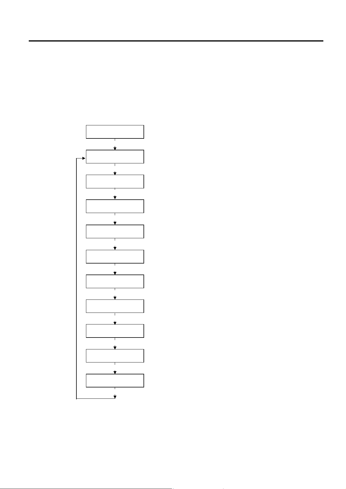
2. SYSTEM MODE EO13-33002
[
[
[
2.3 Printer Parameter Fine Adjustment
2.3 Printer Parameter Fine Adjustment
Outline of Printer Parameter Fine Adjustment
In the Printer Parameter Fine Adjustment mode, you can fine adjust each parameter, such as Print tone,
Print start position, Threshold, etc. which are set by the PC command. This is useful when using several
types of media by turns or when the print start position or cut/strip position is required to be fine adjusted.
The Printer Parameter Fine Adjustment menu contains the following.
<3>ADJUST SET
[PAUSE]
<3>ADJUST SET
FEED ADJ.+10.0mm
[PAUSE]
<3>ADJUST SET
CUT ADJ. +10.0mm
[PAUSE]
<3>ADJUST SET
BACK ADJ. +5.0mm
[PAUSE]
<3>ADJUST SET
X ADJUST +50.0mm
PAUSE]
<3>ADJUST SET
TONE ADJ.<T> +3
[PAUSE]
<3>ADJUST SET
TONE ADJ.<D> -2
[PAUSE]
<3>ADJUST SET
RBN ADJ <FW> -10
[PAUSE]
<3>ADJUST SET
RBN ADJ <BK> -5
PAUSE]
<3>ADJUST SET
THRESHOLD<R>1.0V
[PAUSE]
<3>ADJUST SET
THRESHOLD<T>1.4V
PAUSE]
Print Start Positino Fine Adjustment
Cut/Strip Position Fine Adjustment
Reverse Feed Amount Fine Adjustment
X Coordinate Fine Adjustment
Print Tone Fine Adjustment (Thermal Transfer)
Print Tone Fine Adjustment (Thermal Direct)
Ribbon Motor Drive Voltage Fine Adjustment (Take-up Motor)
Ribbon Motor Drive Voltage Fine Adjustment (Feed Motor)
Threshold Fine Adjustment (Black Mark Sensor)
Threshold Fine Adjustment (Feed Gap Sensor)
2-35
Page 42

2. SYSTEM MODE EO13-33002
2.3 Printer Parameter Fine Adjustment
How to Enter Printer Parameter Fine Adjustment Mode
Turn on the printer while pressing the [FEED] and [PAUSE] keys at the same time. Hold both keys until the
“<1>DIAG. Vx.x” Message appears.
<1>DIAG. Vx.x
Press the [FEED] key twice.
The printer is at the start of the Printer Parameter Fine Adjustment menu.
<3>ADJUST SET
NOTES: 1. When pressing the [FEED] and [RESTART] keys at the same time in the parameter setting, the
message returns to “<3>ADJUST SET”.
2. If holding the [FEED] or [RESTART] key for 0.5 seconds or longer in the Printer Parameter Fine
Adjustment, the key is entered continuously.
3. A changed parameter becomes effective by pressing the [PAUSE].
4. Use the [FEED] or [RESTART] key to select a desired value or option.
2-36
Page 43

2. SYSTEM MODE EO13-33002
2.3 Printer Parameter Fine Adjustment
2.3.1 Print Start Position Fine Adjustment
This parameter is to fine adjust a print start position after printing (= to fine adjust the feed amount to the
next media’s print start position).
When “<3>ADJUST SET” appears, press the [PAUSE] key.
<3>ADJUST SET
FEED ADJ. +0.0mm
Use the [FEED] or [RESTART] key to select a desired option. (Range: -50.0 mm to +50.0 mm)
After completing the fine adjustment, press the [PAUSE] key.
• Print Start Position Fine Adjustment (Example)
[RESTART]
[FEED]
[FEED] key: Pressing the [FEED] key one time causes a –0.1 mm change, up to –50.0 mm.
[RESTART] key: Pressing the [RESTART] key one time causes a +0.1 mm change, up to +50.0 mm.
FEED ADJ.+50.0mm
FEED ADJ.+49.9mm
FEED ADJ.+0.1mm
FEED ADJ.+0.0mm
FEED ADJ.-0.1mm
FEED ADJ.-49.9mm
FEED ADJ.-50.0mm
NOTE: The fine adjustment value equals to the sum of the fine adjustment values set by the PC command and
this parameter.
The maximum print position fine adjustment value is +
the value remains unchanged even if the subsequent fine adjustment is performed.
50.0 mm. When the value reached the maximum,
2-37
Page 44

2. SYSTEM MODE EO13-33002
3mm3
2.3 Printer Parameter Fine Adjustment
2.3.2 Cut/Strip Position Fine Adjustment
This parameter is to fine adjust a cut or strip position.
When “<3>ADJUST SET” appears, press the [PAUSE] key twice.
Use the [FEED] or [RESTART] key to select a desired option. (Range: -50.0 mm to +50.0 mm)
After completing the fine adjustment, press the [PAUSE] key.
• Example of Cut Position Fine Adjustment
When setting +3.0 mm
Compared with “+0.0 mm” position,
When setting +0.0 mm
When setting –3.0 mm
Compared with “+0.0 mm” position,
NOTES: 1. Cut issue is available only when the optional cutter unit (B-SX208-QM-R) is installed.
2. The fine adjustment value equals to the sum of the fine adjustment values set by the PC command
<3>ADJUST SET
CUT ADJ. +0.0mm
CUT ADJ.+50.0mm
[RESTART]
[FEED]
[FEED] key: Pressing the [FEED] key one time causes a –0.1 mm change, up to –50.0 mm.
[RESTART] key: Pressing the [RESTART] key one time causes a +0.1 mm change, up to +50.0 mm.
CUT ADJ.+49.9mm
CUT ADJ.+0.1mm
CUT ADJ.+0.0mm
CUT ADJ.-0.1mm
CUT ADJ.-49.1mm
CUT ADJ.-50.0mm
the cut position is shifted forward.
Feed Direction
Cut Position
Feed Direction
mm
Cut Position
the cut position is shifted backward.
Feed Direction
Cut Position
and this parameter.
The maximum cut position fine adjustment value is +50.0 mm. When the value reached the
maximum, the value remains unchanged even if the subsequent fine adjustment is performed.
2-38
Page 45
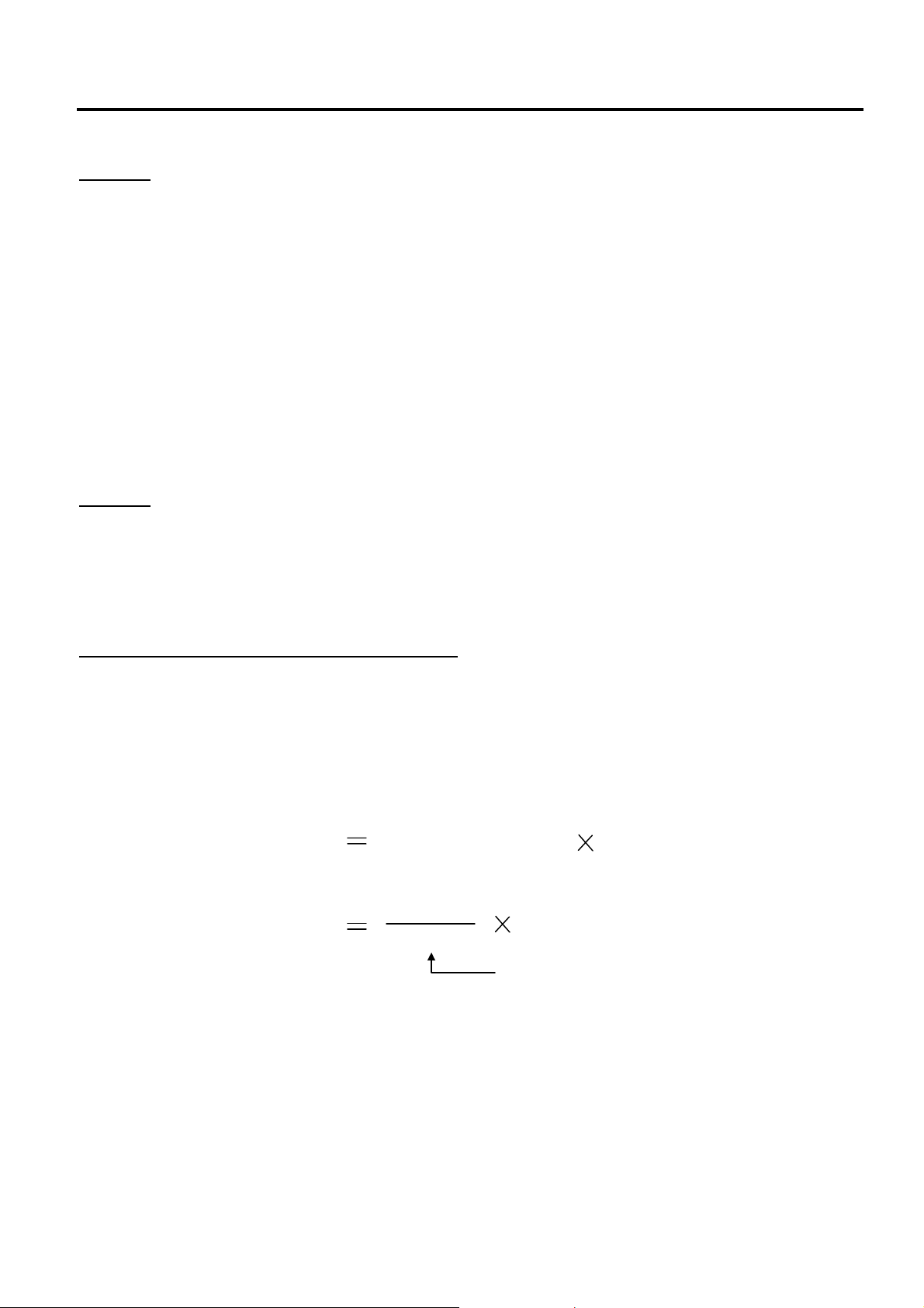
2. SYSTEM MODE EO13-33002
p
2.3 Printer Parameter Fine Adjustment
[Handling of labels having the label pitch of less than 38 mm in cut issue mode]
Method 1
Under the conditions described below, the printer performs as follows in cut issue mode.
Head up → Forward feed to the cut position → Head down → Cut → Head up → Reverse feed to the
home position → Head down
Condition: When receiving the issue command, feed command, eject command
label pitch: 38.0 mm or less, with cutter, transmissive sensor
cut position fine adjustment: ±10.0 mm or less, issue mode: C
* A head up/down is performed only when the ribbon saving module is installed. When it is not installed,
use Method 2.
NOTES: 1. Although a label, being fed to be cut, cannot be fed any more because its trailing edge has already
passed the feed roller during head up, no error is detected.
2. The print head may not be raised depending on the rise of the solenoid’s temperature for head up
operation in cut issue mode.
Method 2
The minimum label pitch in normal cut issue mode is 38.0 mm. When a label stock having the pitch of less
than 38.0 mm is used (although it is out of specification), an edge of a label may be caught by an edge of
the thermal head during a back feed to the home position after the cutter is cut in a gap area between labels.
This may prevent the label from being fed back to the proper home position. In such a case, perform the
method below to solve the problem.
Prevention by fine adjustment of the cut position
NOTE: Use of this method will cause one or more printed labels to be left between the print head and the cutter.
These labels should be removed by an issue or a label feed.
(a) Calculation of a cut position fine adjustment value
A cut position fine adjustment value is calculated using the following formula.
If the label is not fed back to the proper home position even by using the value obtained, the cut position
should be adjusted using any other value.
Cut position fine adjustment value
The number of labels left
between the print head
and the cutter
Label pitch
32.8 mm
Label
itch
Label pitch
(Round down any decimals.)
Example) Label pitch: 30.0 mm
Cut position fine adjustment value = (32.8 mm / 20.0 mm) x 30.0 mm
= 1 x 30.0 mm
= +30.0 mm
2-39
Page 46
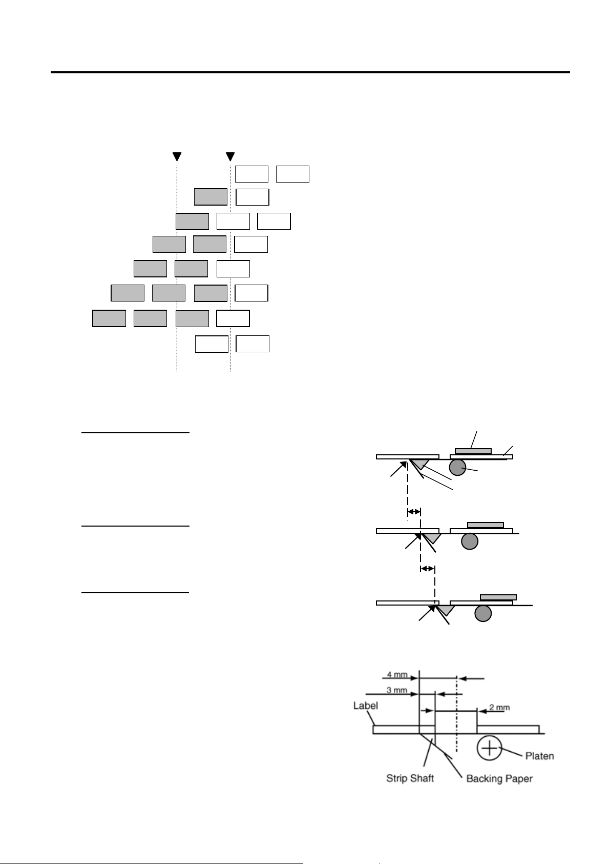
2. SYSTEM MODE EO13-33002
A
A
A
A
A
A
A
Label
Print Head
Backi
3
St
iti
r
St
iti
r
3
2.3 Printer Parameter Fine Adjustment
(b) Operation example
Issue count: 3, Cut interval: 1
Cut
position
Print head
position
B
B
B
C
C
(1) Idling
B
(2) Printing Label A has been finished.
(3) While Label B is being printed, the front gap of
label A is cut off.
(4) Printing Label B has been finished.
B
C
B
C
B
C
(5) While Label C is being printed, the front gap of
label B is cut off.
(6) Printing Label C has been finished.
(7) Label C is fed to the cut position, then this
Label is cut off.
C
(8) Label C is fed backward to the home position.
• Example of Strip Position Fine Adjustment
When setting +3.0 mm
Compared with “+0.0mm” position, the stop
position after printing is shifted forward.
When setting +0.0 mm
Stop position after
printing
mm
Platen
Strip Plate
ng Paper
op pos
on afte
printing
mm
When setting –3.0 mm
Compared with “+0.0mm” position, the stop
position after printing is shifted backward.
op pos
on afte
printing
NOTE: The print stop position when printing the label in strip
mode varies according to label length as the strip mode
printing stops so that the edge of the strip shaft is 4 mm
from the middle of the gap. This is because the gap
length is programmed as 2 mm. When the gap length
is 5 mm or more, the effective print length should be set
to the value obtained by subtracting 2 mm from the
label pitch, that is, set the gap length to 2 mm. If the
print format hangs over the gap as a result, correct
the
print start position.
2-40
Page 47

2. SYSTEM MODE EO13-33002
2.3 Printer Parameter Fine Adjustment
2.3.3 Reverse Feed Amount Fine Adjustment
This parameter is to fine adjust a reverse feed amount.
When “<3>ADJUST SET” appears, press the [PAUSE] key until the following display appears.
<3>ADJUST SET
BACK ADJ. +5.0mm
Use the [FEED] or [RESTART] key to select a desired option. (Range: -9.9 mm to +9.9 mm)
[RESTART]
[FEED]
[FEED] key: Pressing the [FEED] key one time causes a –0.1 mm change, up to –9.9 mm.
[RESTART] key: Pressing the [RESTART] key one time causes a +0.1 mm change, up to +9.9 mm.
After completing the fine adjustment, press the [PAUSE] key.
• Example of Reverse Feed Amount Fine Adjustment
When setting +3.0 mm
Compared with “+0.0mm” position, the stop
position after printing is shifted forward.
When setting +0.0 mm
When setting –3.0 mm
Compared with “+0.0mm” position, the stop
position after printing is shifted backward.
BACK ADJ.+9.9mm
BACK ADJ.+9.8mm
BACK ADJ.+0.1mm
BACK ADJ.+0.0mm
BACK ADJ.-0.1mm
BACK ADJ.-9.8mm
BACK ADJ.-9.9mm
Feed Direction
Feed Direction
Feed Direction
3mm
Print Start Position after a
reverse feed
Print Start Position after a
3mm
reverse feed
Print Start Position after a
reverse feed
2-41
Page 48
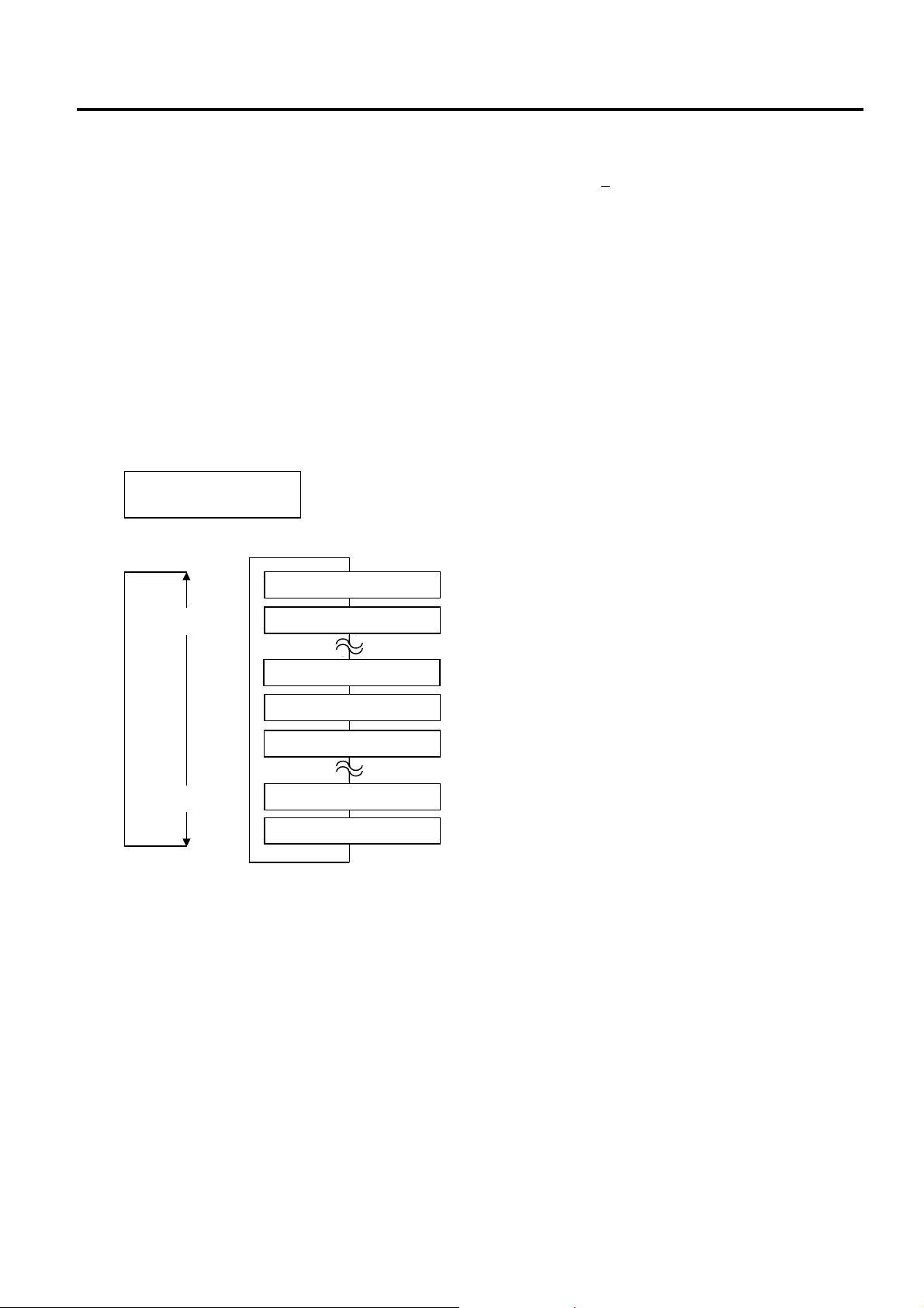
2. SYSTEM MODE EO13-33002
2.3 Printer Parameter Fine Adjustment
NOTES:
1. The fine adjustment value equals to the sum of the fine adjustment values set by the PC command and this
parameter. The maximum reverse feed amount fine adjustment value is +
the maximum, the value remains unchanged even if the subsequent fine adjustment is performed.
2. There may be cases where a label is not returned to the home position depending on the print conditions,
even if a reverse feed amount is the same as a forward feed amount.
When an operation including a reverse feed (cut issue, strip issue, forward feed standby after an issue) is
performed using a sensor, a label/tag may not be returned to the home position resulting an error, if the label
pitch length is almost the same as the distance between the thermal print head and the paper sensor (69.8
mm). To prevent this problem, the reverse feed amount should be increased by performing the reverse feed
amount fine adjustment in the + direction.
9.9 mm. When the value reached
2.3.4 X Coordinate Fine Adjustment
This parameter is to fine adjust the print position on X coordinate.
When “<3>ADJUST SET” appears, press the [PAUSE] key until the following display appears.
<3>ADJUST SET
X ADJUST +5.0mm
Use the [FEED] or [RESTART] key to select a desired option. (Range: -99.9 mm to +99.9 mm)
[RESTART]
[FEED] key: Pressing the [FEED] key one time causes a –0.1 mm change, up to –99.9 mm.
[RESTART] key: Pressing the [RESTART] key one time causes a +0.1 mm change, up to +99.9 mm.
[FEED]
After completing the fine adjustment, press the [PAUSE] key.
X ADJUST +99.9mm
X ADJUST +99.8mm
X ADJUST +0.1mm
X ADJUST +0.0mm
X ADJUST -0.1mm
X ADJUST -99.8mm
X ADJUST -99.9mm
2-42
Page 49

2. SYSTEM MODE EO13-33002
Y
2.3 Printer Parameter Fine Adjustment
• Example of X Coordinate Fine Adjustment
When setting –50.0 mm
Feed Direction
Compared with “+0.0mm” position, the print
position is shifted to the left.
When setting +0.0 mm
Top Down Printing
Y
50.0mm
X
ABC
Bottom First Printing
X
When setting +50.0 mm
ABC
Compared with “+0.0mm” position, the print
position is shifted to the right.
50.0mm
ABC
NOTES:
1. The X coordinate fine adjustment is performed to fine adjust the print position in horizontal direction (left or
right).
2. Adjust the X coordinate within the effective print range. After the value reaches the coordinate 0, the value
remains unchanged even if the subsequent fine adjustment is performed in the negative direction.
3. This adjustment cannot be used in the Self Test mode or Test print.
4. The fine adjustment value equals to the sum of the fine adjustment values set by the PC command and this
parameter. The maximum X coordinate fine adjustment value is +
99.9 mm. When the value reached the
maximum, the value remains unchanged even if the subsequent fine adjustment is performed.
2-43
Page 50
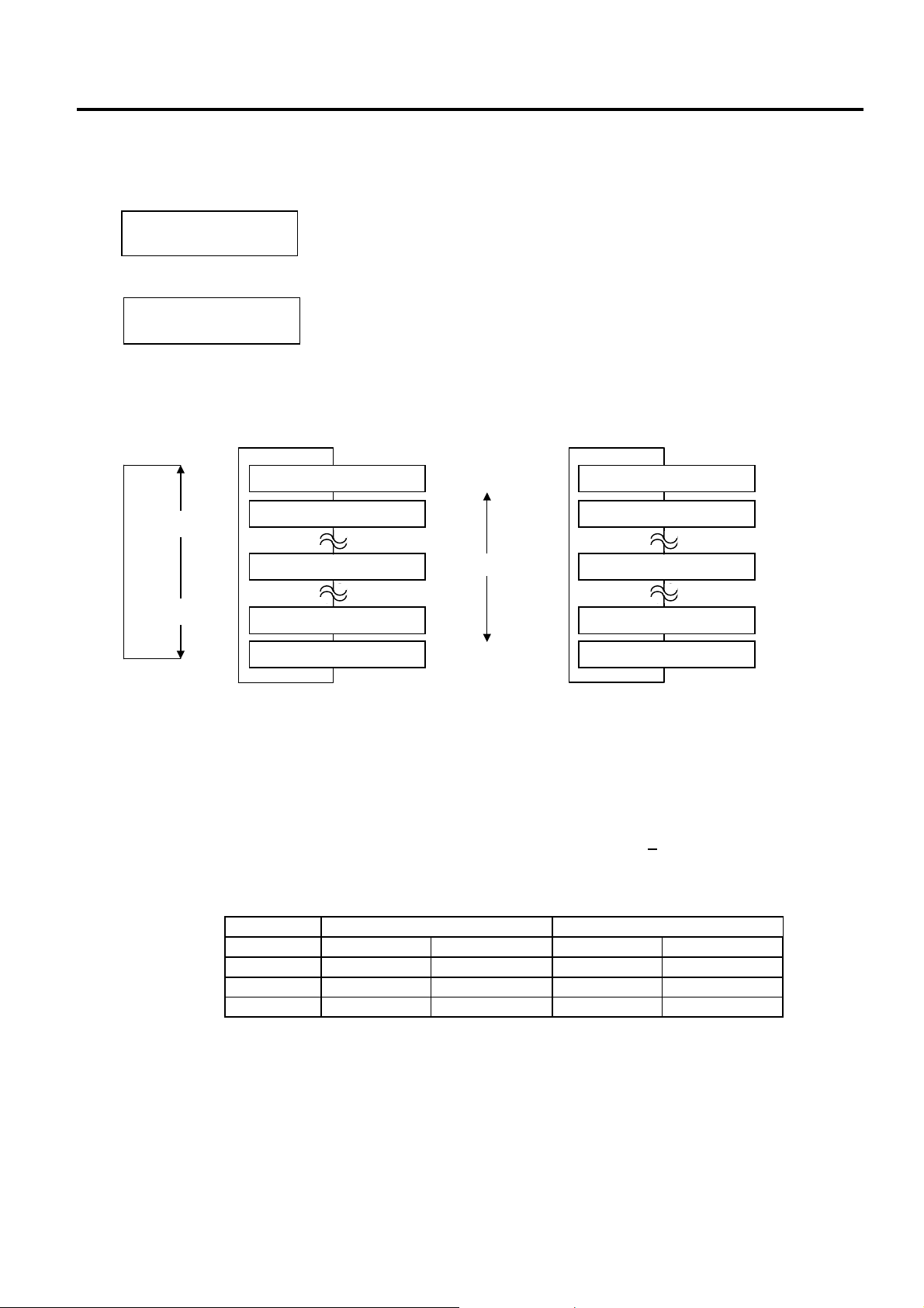
2. SYSTEM MODE EO13-33002
2.3 Printer Parameter Fine Adjustment
2.3.5 Print Tone Fine Adjustment (Thermal Transfer/Thermal Direct Print)
This parameter is to fine adjust the Print Tone.
When “<3>ADJUST SET” appears, press the [PAUSE] key until the following display appears.
<3>ADJUST SET
TONE ADJ.<T> +0
To fine adjust the print tone for thermal direct printing, press the [PAUSE] key again.
<3>ADJUST SET
TONE ADJ.<D> +0
When the LCD display shows “TONE ADJ.<T>” or “TONE ADJ.<D>”, select a desired value with the
[FEED] or [RESTART] key. (Range: -10 to +10)
Thermal Transfer Print Thermal Direct Print
[RESTART]
TONE ADJ<T>. +10
TONE ADJ<T>. +9
TONE ADJ<T>. +0
[FEED]
TONE ADJ<T>. -9
TONE ADJ<T>. -10
[FEED] key: Pressing the [FEED] key one time causes a –1 tone change, up to –10 tones.
[RESTART] key: Pressing the [RESTART] key one time causes a +1 tone change, up to +10 tones.
After completing the fine adjustment, press the [PAUSE] key.
NOTES: 1. The fine adjustment value equals to the sum of the fine adjustment values set by the PC command
and this parameter. The maximum print tone fine adjustment value is +
shows the maximum fine adjustment value for each print speed. Even if the set value exceeds the
maximum value, it will be automatically corrected to the following value.
Print Tone for thermal transfer printing
Print tone for thermal direct printing
Darker
Standard
Lighter
TONE ADJ<D>. +10
TONE ADJ<D>. +9
TONE ADJ<D>. +0
TONE ADJ<D>. -9
TONE ADJ<D>. -10
10. The following table
Maximum fine adjustment value
B-SX6T B-SX8T
Print speed Thermal direct Thermal transfer Thermal direct Thermal transfer
3 ips +10 step +10 step +10 step +10 step
4 ips +5 step +5 step +5 step +5 step
8 ips +2 step +2 step +2 step +2 step
2. This is useful when print tone is required to be fine adjusted.
e.g.) When the ribbon is changed to different type.
2-44
Page 51

2. SYSTEM MODE EO13-33002
2.3 Printer Parameter Fine Adjustment
2.3.6 Ribbon Motor Voltage Fine Adjustment (Feed/Take-up Motor)
This parameter is to fine adjust the Ribbon Motor Voltage (Torque).
When the ribbon is slack or wrinkled and printing is affected, fine adjust the ribbon motor torque by using
the following procedure.
When “<3>ADJUST SET” appears, press the [PAUSE] key until the following display appears.
<3>ADJUST SET
RBN ADJ<FW> +0
To fine adjust the ribbon feed motor voltage, press the [PAUSE] key again.
<3>ADJUST SET
RBN ADJ<BK> +0
When the LCD display shows “RBN ADJ<FW>” or “RBN ADJ<BK>”, select a desired option with the
[FEED] or [RESTART] key. (Range: -15 to +0 for take-up motor / -15 to +10 for feed motor)
RBN ADJ<FW> +0
[RESTART]
RBN ADJ<FW> -1
RBN ADJ<FW> -2
[FEED]
RBN ADJ<FW> -14
RBN ADJ<FW> -15
[FEED] key: Pressing the [FEED] key one time causes a –1 step change, up to –15 steps.
[RESTART] key: Pressing the [RESTART] key one time causes a +1 step change, up to +0 steps for take-
up motor / +10 for feed motor.
After completing the fine adjustment, press the [PAUSE] key.
NOTES: 1. The fine adjustment value equals to the sum of the fine adjustment values set by the PC command
and this parameter. The maximum ribbon motor voltage fine adjustment value is -15. When the
value reached the maximum, the value remains unchanged even if the subsequent fine adjustment
is performed.
2. One step corresponds to 5% of the standard voltage and up to 75% of the voltage can be
decreased.
3. Please make this adjustment if a ribbon error occurs though the ribbon is proper.
Ribbon take-up motor voltage
Ribbon feed motor voltage
Take-up Motor Feed Motor
RBN ADJ<BK> +10
RBN ADJ<BK> +9
RBN ADJ<BK> +8
RBN ADJ<BK> -14
RBN ADJ<BK> -15
Ribbon motor torque
High
Standard
Low
2-45
Page 52

2. SYSTEM MODE EO13-33002
2.3 Printer Parameter Fine Adjustment
2.3.7 Threshold Manual Fine Adjustment (Black Mark/Feed Gap Sensor)
This parameter is to set a threshold voltage of the black mark sensor or feed gap sensor.
When pre-printed media is used, and if the black mark sensor or feed gap sensor cannot properly detect a
print start position even after an automatic threshold setting has been performed, set a threshold voltage
here.
Usually, a threshold is a midpoint between the voltage at a print area and the voltage at a black mark (black
mark sensor) or a gap (feed gap sensor).
When “<3>ADJUST SET” appears, press the [PAUSE] key until the following display appears.
<3>ADJUST SET
THRESHOLD<R>1.0V
To set the threshold for the feed gap sensor, press the [PAUSE] key again.
<3>ADJUST SET
THRESHOLD<T>1.4V
When the LCD display shows “THRESHOLD<R>” or “THRESHOLD<T>”, select a desired value with the
[FEED] or [RESTART] key. (Range: 0.0V to 4.0V)
Black Mark Sensor Feed Gap Sensor
THRESHOLD<R>4.0V
[RESTART]
THRESHOLD<R>3.9V
THRESHOLD<R>3.8V
[FEED]
THRESHOLD<R>0.1V
THRESHOLD<R>0.0V
[FEED] key: Pressing the [FEED] key one time causes a –0.1V change, up to 0.0V.
[RESTART] key: Pressing the [RESTART] key one time causes a +0.1V change, up to +4.0V.
After completing the fine adjustment, press the [PAUSE] key.
NOTE: If “0.0V” is set as a threshold voltage, it will be automatically changed to the initial value when the printer
is turned off and back to on.
THRESHOLD<R>: 1.4V
THRESHOLD<T>: 1.0V
Threshold setting for the black mark sensor
Threshold setting for the feed gap sensor
THRESHOLD<T>4.0V
THRESHOLD<T>3.9V
THRESHOLD<T>3.8V
THRESHOLD<T>0.1V
THRESHOLD<T>0.0V
2-46
Page 53

2. SYSTEM MODE EO13-33002
A
A
A
A
A
A
A
(3 dots)
A
A
2.4 Test Print
2.4 Test Print
Outline of Test Print
In the Test Print mode, you can print the test patterns and set print conditions for a test print. This is useful
to check the print quality of new media or ribbon.
The Test Print menu consists of the following:
uto print mode
for factory test
(Black mark sensor)
<4>TEST PRINT
[RESTART]
UTO PRINT(REFL)
The printer feeds one media, and
then prints 5 pcs. of the Slant Line
.
<4>TEST PRINT
UTO PRINT(REFL)
The printer prints 5 pcs. of the Bar
Code.
<4>TEST PRINT
UTO PRINT(REFL)
The printer prints 5 pcs. of
characters.
<4>TEST PRINT
<4>TEST PRINT
UTO PRINT(TRAN)
The printer feeds one media, and
then prints 5 pcs. of the Slant Line
(3 dots).
<4>TEST PRINT
UTO PRINT(TRAN)
The printer prints 5 pcs. of the
Bar Code.
<4>TEST PRINT
UTO PRINT(TRAN)
The printer prints 5 pcs. of
characters.
Regular mode
Test pattern selection
[PAUSE]
[PAUSE]
[PAUSE]
[PAUSE]
[PAUSE]
[PAUSE]
[PAUSE]
<4>TEST PRINT
[PAUSE]
<4>TEST PRINT
PRINT CONDITION
[FEED]
[RESTART]
<4>TEST PRINT
SLANT LINE(1DOT)
[FEED]
[RESTART]
<4>TEST PRINT
SLANT LINE(3DOT)
[FEED]
[RESTART]
<4>TEST PRINT
CHARACTERS
[FEED]
[RESTART]
<4>TEST PRINT
BARCODE
[FEED]
[RESTART]
<4>TEST PRINT
NON-PRINTING
[FEED]
[RESTART]
<4>TEST PRINT
FACTORY TEST
[FEED]
[RESTART]
<4>TEST PRINT
UTO PRINT(TRAN)
[FEED]
[RESTART]
<4>TEST PRINT
UTO PRINT(REFL)
[FEED]
[RESTART]
[PAUSE]
Issue
Regular mode
Print condition setting
[PAUSE]
<4>TEST PRINT
ISSUE COUNT 1
Use the [FEED] or [RESTART]
key to select a desired option.
[PAUSE]
<4>TEST PRINT
PRINT SPEED 4”/s
Use the [FEED] or [RESTART]
key to select a desired option.
[PAUSE]
<4>TEST PRINT
SENSOR TRANS.
Use the [FEED] or [RESTART]
key to select a desired option.
[PAUSE]
<4>TEST PRINT
PRT TYPE TRANSFR
Use the [FEED] or [RESTART]
key to select a desired option.
[PAUSE]
<4>TEST PRINT
TYPE[S] NO CUT
Use the [FEED] or [RESTART]
key to select a desired option.
[PAUSE]
<4>TEST PRINT
LABEL LEN. 76mm
Use the [FEED] or [RESTART]
key to select a desired option.
[PAUSE]
<4>TEST PRINT
PAPER FEED
Use the [FEED] or [RESTART]
key to select a desired option.
[PAUSE]
The printer feeds one media.
2-47
Page 54

2. SYSTEM MODE EO13-33002
2.4 Test Print
How to Enter Test Print Mode
While pressing the [FEED] and [PAUSE] keys at the same time, turn on the printer. Hold both keys until
the “<1>DIAG. Vx.x” Message appears.
<1>DIAG. Vx.x
Press the [FEED] key 3 times.
The Test Print is ready to be performed.
<4>TEST PRINT
NOTES: 1. When pressing the [FEED] and [RESTART] keys at the same time in the Test Print menu, the
message returns to “<4>TEST PRINT”.
2. If holding the [FEED] or [RESTART] key for 0.5 seconds or longer in the Test Print menu, the key is
entered continuously.
3. The fine adjustment parameters are effective for the Test Print. (except for X Axis Fine Adjustment.)
4. If any error occurs, an error message appears, and the printer stops printing. After clearing the
errors, press the [PAUSE] key to return to the System Mode menu. The printer does not restart
printing automatically.
5. A changed parameter becomes enabled by pressing the [PAUSE] key.
6. A label size greater than the image buffer length cannot be designated. If designated, the printer
prints in the image buffer, or the printer stops because of an error.
7. The ribbon saving function automatically starts when the space area is as described below if the
ribbon saving function parameter is set to ON and thermal transfer is selected for the printing mode:
• 3”/sec: 20 mm or more
• 4”/sec: 20 mm or more
• 8”/sec: 30 mm or more
8.
9.
Media
T
E
Ribbon Save Area
8 mm
Ribbon Save Area
C
2-48
Page 55
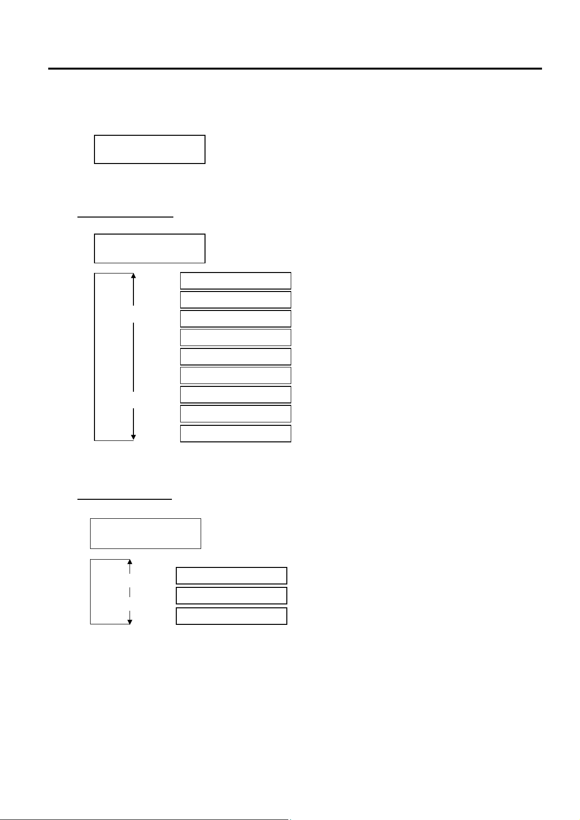
2. SYSTEM MODE EO13-33002
2.4 Test Print
2.4.1 Specifying the Print Condition for the Test Print
The print conditions for the Test Print should be specified before printing.
When “<4>TEST PRINT” appears, press the [PAUSE] key.
To set the print conditions, press the [PAUSE] key.
Issue Count Setting
Select an issue count from a range of 1 to 5000.
After selecting an issue count, press the [PAUSE] key to go to Print Speed Setting.
Print Speed Setting
Select a print speed for the test print among 8”/sec., 4”/sec., and 3”/sec.
After selecting a print speed, press the [PAUSE] key to go to Sensor Type Selection.
<4>TEST PRINT
PRINT CONDITION
<4>TEST PRINT
ISSUE COUNT 1
[RESTART]
[FEED]
<4>TEST PRINT
PRINT SPEED 4”/s
[RESTART]
[FEED]
ISSUE COUNT 5000
ISSUE COUNT 1000
ISSUE COUNT 500
ISSUE COUNT 100
ISSUE COUNT 50
ISSUE COUNT 10
ISSUE COUNT 5
ISSUE COUNT 3
ISSUE COUNT 1
PRINT SPEED 8”/s
PRINT SPEED 4”/s
PRINT SPEED 3”/s
2-49
Page 56

2. SYSTEM MODE EO13-33002
2.4 Test Print
Sensor Type Selection
Select a sensor type among “TRANS” (Feed Gap Sensor), “REFLECT” (Black Mark Sensor) and
“NONE”.
<4>TEST PRINT
SENSOR TRANS.
[RESTART]
[FEED]
SENSOR NONE
SENSOR REFLECT.
SENSOR TRANS.
None
Black Mark Sensor
Feed Gap Sensor
After selecting a sensor type, press the [PAUSE] key to go to Printing Mode Selection.
NOTE: Select a sensor type which is proper for the media being used. Basically, the Reflective Sensor
(Black Mark Sensor) is for tag paper, and the Transmissive Sensor (Feed Gap Sensor) is for label.
Printing Mode Selection
Select a printing mode for the test print among “TRANSFR” (Thermal transfer: transparent ribbon),
“NO TRAN” (Thermal transfer: non transparent ribbon), and “DIRECT” (Thermal direct).
<4>TEST PRINT
PRT TYPE TRANSFR
[RESTART]
[FEED]
PRT TYPE TRANSFR
PRT TYPE NO TRAN
PRT TYPE DIRECT
Thermal Transfer: Transparent ribbon
Thermal Transfer: Non transparent ribbon
Thermal Direct
After selecting a printing mode, press the [PAUSE] key to go to Issue Mode Selection.
NOTE: Select a printing mode which is proper for the operating conditions. Basically, the Thermal
Transfer is for the use of ribbon, and the Thermal Direct is for the use of thermal paper.
Issue Mode Selection
Select an issue mode for the test print among “[S]NO CUT” (Batch mode without cut), “[C]WITH CUT”
(Cut mode), and “[H]PEEL OFF” (Strip mode).
<4>TEST PRINT
TYPE[S]NO CUT
[RESTART]
[FEED]
TYPE[S]NO CUT
TYPE[C]WITH CUT
TYPE[H]PEEL OFF
Batch mode without cut
Cut mode
Strip mode
After selecting an Issue Mode, press the [PAUSE] key to go to Media Length Setting.
NOTE: Cut mode is available only when the optional cutter module (B-SX208-QM-R) is installed. Strip
mode is available only when the optional strip module (B-SX908-H-QM-R) is installed.
2-50
Page 57

2. SYSTEM MODE EO13-33002
2.4 Test Print
Media Length Setting
Select a label length for the test print from a range of 5 mm to 999 mm.
<4>TEST PRINT
LABEL LEN. 76mm
[RESTART]
[FEED]
LABEL LEN. 999mm
LABEL LEN. 5mm
[FEED] key: Pressing the [FEED] key one time causes a –1 mm change, up to 5 mm.
[RESTART] key: Pressing the [RESTART] key one time causes a +1 mm change, up to 999 mm.
After selecting a media length, press the [PAUSE] key to go to Paper Feed Selection.
NOTE: Pressing and holding the [RESTART] or [FEED] key causes the display to show the values quickly
and continuously. To stop it, release the key.
Paper Feed Selection
Select whether or not a paper feed is performed prior to a test print.
<4>TEST PRINT
PAPER FEED
[RESTART]
[FEED]
PAPER FEED
PAPER NO FEED
Paper feed is performed.
Paper feed is not performed.
After selecting whether to perform a paper feed, press the [PAUSE] key. The display returns to the
“<4>TEST PRINT”.
NOTE: When “PAPER FEED” is selected, the printer feeds the media prior to a test print to adjust the
print start position. When “PAPER NO FEED” is selected, the printer starts printing without
print start position adjustment. If the print start position adjustment is unnecessary, you can
save the media by selecting “PAPER NO FEED”.
2-51
Page 58

2. SYSTEM MODE EO13-33002
2.4 Test Print
2.4.2 Test Print Pattern Selection
Several print patterns are provided for test print.
When “<4>TEST PRINT” appears after paper feed selection, press the [PAUSE] key.
Use the [FEED] or [RESTART] key to select a desired option.
<4>TEST PRINT
PRINT CONDITION
[RESTART]
[FEED]
PRINT CONDITION
SLANT LINE(1DOT)
SLANT LINE(3DOT)
CHARACTERS
BARCODE
NON-PRINTING
FACTORY TEST
AUTO PRINT(TRAN)
AUTO PRINT(REFL)
2-52
Page 59

2. SYSTEM MODE EO13-33002
2.4 Test Print
2.4.3 Slant Line (1 dot)
Pressing the [PAUSE] key while SLANT LINE (1 DOT) is displayed causes the slant line patterns (1 dot) to
be printed.
After printing is completed, the display returns to “<4>TEST PRINT”.
Pressing the [PAUSE] key causes the display to show “SLANT LINE (1 DOT)” again. Then, press the
[FEED] key to display “SLANT LINE (3 DOT)”.
SLANT LINE(1DOT)
Print Sample of Slant Line (1 dot)
(Magnified view: Print ratio 16.7%)
2-53
Page 60
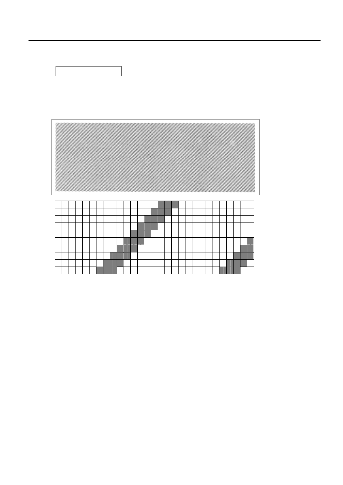
2. SYSTEM MODE EO13-33002
2.4 Test Print
2.4.4 Slant Line (3 dots)
Pressing the [PAUSE] key while SLANT LINE (3 DOT) is displayed causes the slant line patterns (3 dots) to
be printed.
After printing is completed, the display returns to “<4>TEST PRINT”.
Pressing the [PAUSE] key causes the display to show “SLANT LINE (3DOT)” again. Then, press the
[FEED] key to display “CHARACTERS”.
SLANT LINE(3DOT)
Print Sample of Slant Line (3 dots)
(Magnified view: Print ratio 16.7%)
2-54
Page 61

2. SYSTEM MODE EO13-33002
2.4 Test Print
2.4.5 Characters
Pressing the [PAUSE] key while CHARACTERS is displayed causes the characters to be printed.
CHARACTERS
Print Sample of Characters
After printing is completed, the display returns to “<4>TEST PRINT”.
Pressing the [PAUSE] key causes the display to show “CHARACTERS” again. Then, press the [FEED]
key to display “BARCODE”.
2.4.6 Barcode
Pressing the [PAUSE] key while BARCODE is displayed causes the bar codes to be printed.
BARCODE
Print Sample of Barcodes
After printing is completed, the display returns to “<4>TEST PRINT”.
Pressing the [PAUSE] key causes the display to show “BARCODE” again. Then, press the [FEED] key to
display “NON-PRINTING”.
2-55
Page 62

2. SYSTEM MODE EO13-33002
2.4 Test Print
2.4.7 Non-Printing
Pressing the [PAUSE] key while NON-PRINTING is displayed causes a blank media to be issued.
NOTE: The Non-Printing function looks like a media feeding.
NON-PRINTING
Print Sample of Non-print
After printing is completed, the display returns to “<4>TEST PRINT”.
Pressing the [PAUSE] key causes the display to show “NON-PRINTING” again. Then, press the [FEED]
key to display “FACTORY TEST”.
2.4.8 Factory Test
Pressing the [PAUSE] key while FACTORY TEST is displayed causes the factory test pattern to be printed.
After printing is completed, the display returns to “<4>TEST PRINT”.
Pressing the [PAUSE] key causes the display to show “FACTORY TEST” again. Then, press the [FEED]
key to display “AUTO PRINT (TRAN)”.
FACTORY TEST
Print Sample of Factory Test
2-56
Page 63

2. SYSTEM MODE EO13-33002
2.4 Test Print
2.4.9 Auto Print
Pressing the [PAUSE] key while AUTO PRINT (TRAN) or AUTO PRINT (REFL) is displayed causes the
following automatic test print:
(1) [PAUSE] key Feeds one media and prints slant lines (3 dots) on 5 pieces of media
(2) [PAUSE] key Prints bar codes on 5 pieces of media
(3) [PAUSE] key Prints characters on 5 pieces of media
NOTES: 1. Select “AUTO PRINT (TRAN)” when using labels, and “AUTO PRINT (REFL)” when using tag
2. Auto print is performed on the conditions below. Parameter setting and print tone fine
Print speed: 8 inches/second
Sensor type: Black mark or feed gap sensor
Printing method: Thermal transfer
Issuing mode: Batch printing
Label size: 76mm
Print tone fine adjustment value:
AUTO PRINT(TRAN)
[FEED]
AUTO PRINT(REFL)
paper with black marks.
adjustment value is ignored.
[RESTART]
Feed Gap Sensor is chosen.
Black Mark Sensor is chosen.
±
0
2-57
Page 64
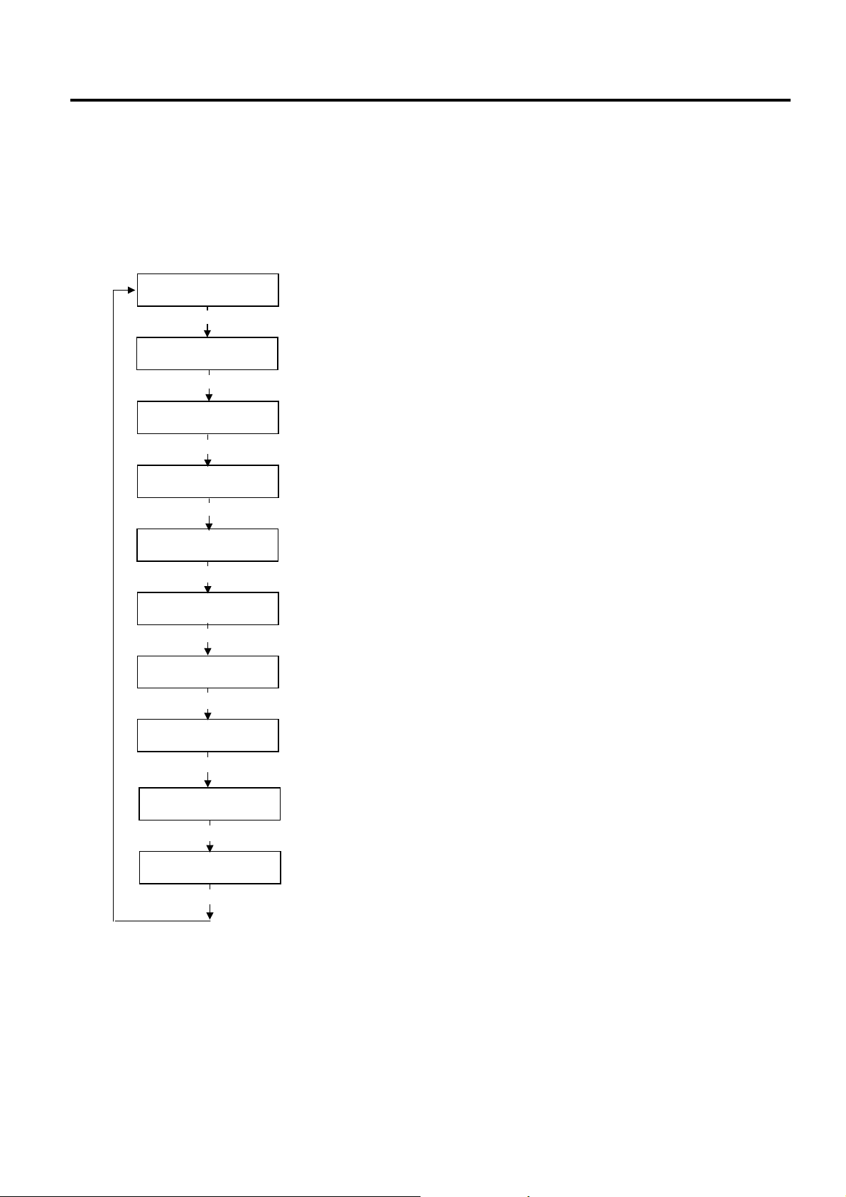
2. SYSTEM MODE EO13-33002
2.5 Sensor Adjustment
2.5 Sensor Adjustment
Outline of the Sensor Adjustment
In the Sensor Adjustment mode, the status of the sensors and thermistors is displayed. Also you can store
media level voltage and media end level voltage for the Black Mark, Feed Gap, and Ribbon End Sensors.
The Sensor Adjustment menu contains the following:
NOTES: 1. Perform a sensor threshold setting after changing the media to a different type.
2. An error related to the print position may be caused by the improperly set sensor threshold. In this
3. When pressing the [FEED] and [RESTART] keys at the same time in the Sensor Adjustment menu,
4. The sensor status is checked every 200 msec. Therefore, the display may change according to the
<5>SENSOR ADJ.
[PAUSE]
<5>SENSOR ADJ.
[H]28°C [A]28°C
[PAUSE]
<5>SENSOR ADJ.
[REFLECT] 3.5V
[FEED] or [RESTART]
<5>SENSOR ADJ.
[REFLECT] 4.8V*
[PAUSE]
<5>SENSOR ADJ.
[TRANS.] 2.4V
[FEED] or [RESTART]
<5>SENSOR ADJ.
[TRANS.] 4.1V*
[PAUSE]
<5>SENSOR ADJ.
[PE]R0.1V T4.8V
[FEED] or [RESTART]
<5>SENSOR ADJ.
[PE]R0.1V T4.8V*
[PAUSE]
<5>SENSOR ADJ.
[RIBBON] 3.1V
[FEED] or [RESTART]
<5>SENSOR ADJ.
[RIBBON] 3.1V*
[PAUSE]
Thermistor Status Display:
Temperatures being detected by the Print Head Thermistor and the
Ambient Thermistor are displayed
Black Mark Sensor Status Display:
Voltage being detected by the Black Mark Sensor is displayed
Black Mark Sensor Adjustment:
Using the media actually used, a “media level” voltage is stored.
Feed Gap Sensor Status Display:
Voltage being detected by the Feed Gap Sensor is displayed.
Feed Gap Sensor Adjustment:
Using the media actually used, a “media level” voltage is stored.
Black Mark Sensor/Feed Gap Sensor Status Display (No media):
“No media level” voltage detected by the Black Mark Sensor/Feed Gap
Sensor is displayed.
Black Mark Sensor/Feed Gap Sensor Adjustment (No media):
“No media level” voltage is stored.
Ribbon End Sensor Status Display:
Voltage being detected by the Ribbon End Sensor is displayed.
Ribbon End Sensor Adjustment:
Using the ribbon actually used, a “ribbon level” voltage is stored.
case please perform a threshold setting in this mode. In case further adjustment is required, refer to
Section 2.3 Printer Parameter Fine Adjustment to make the threshold fine adjustment.
the display returns to “<5>SENSOR ADJ.”.
status.
2-58
Page 65

2. SYSTEM MODE EO13-33002
2.5 Sensor Adjustment
How to Enter the Sensor Adjustment Mode
While pressing the [FEED] and [PAUSE] keys at the same time, turn on the printer. Hold both keys until
the “<1>DIAG. Vx.x” Message appears.
<1>DIAG. Vx.x
Press the [FEED] key 4 times. The printer is at the start of the Sensor Adjustment menu.
<5>SENSOR ADJ.
2.5.1 Thermistor Status Display
When “<5>SENSOR ADJ.” appears, press the [PAUSE] key to display the following.
Press the [PAUSE] key to show a real-time black mark sensor status.
<5>SENSOR ADJ.
[H]20°C [A]22°C
Ambient Temperature Thermistor Status
0 to 86 °C
Print Head Thermistor Status
0 to 86 °C
2.5.2 Black Mark Sensor Adjustment
Follow the procedure below to store a media level voltage of the black mark sensor.
(1) Load a tag stock in the printer so that the Black Mark Sensor detects a print area (no black mark).
(2) Press and hold the [RESTART] or [FEED] key for more than 3 seconds.
(3) Remove the tag stock from the printer.
(4) Press the [PAUSE] key to show a real-time Feed Gap Sensor status.
<5>SENSOR ADJ.
[REFLECT] 3.8V
<5>SENSOR ADJ.
[REFLECT] 2.8V*
Real-time status detected by the Black Mark Sensor
0.0V to 5.0V
When storing a media level voltage is completed, “*” appears.
2-59
Page 66
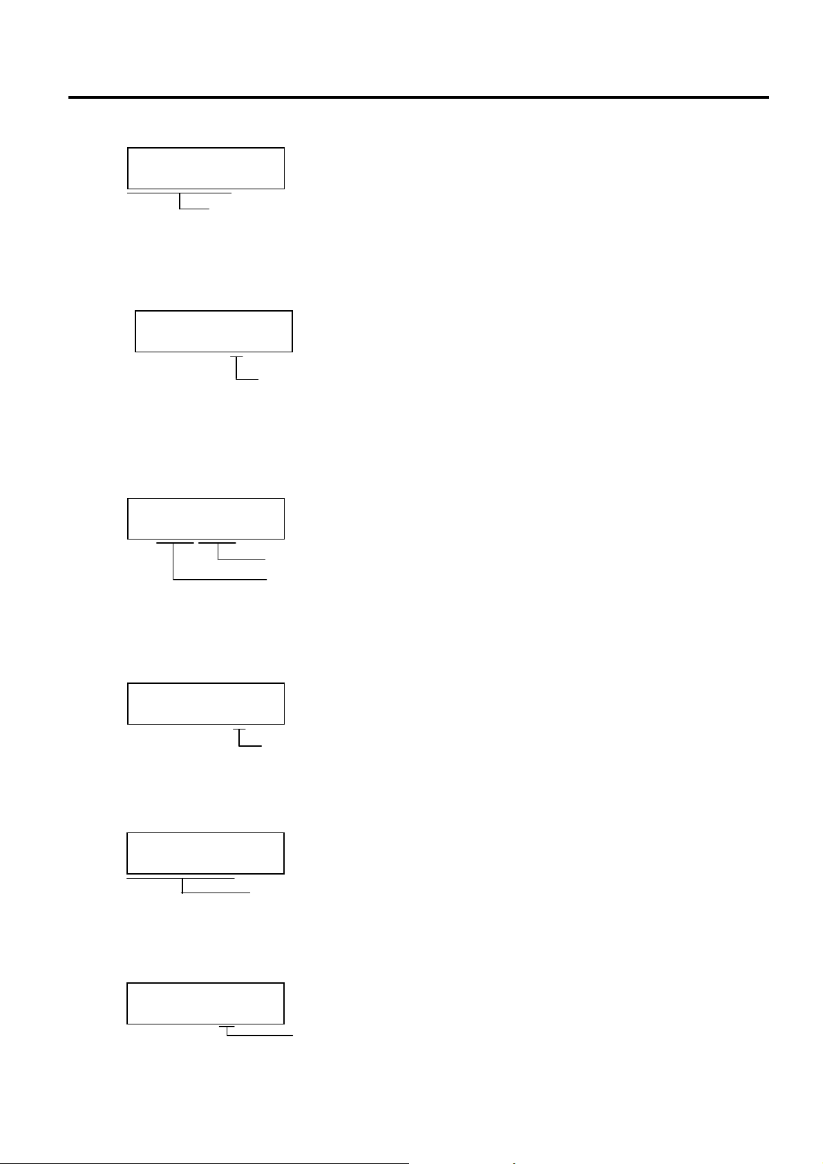
2. SYSTEM MODE EO13-33002
2.5 Sensor Adjustment
2.5.3 Feed Gap Sensor Adjustment
Follow the procedure below to store a backing paper level voltage of the Feed Gap Sensor.
(1) Place the backing paper (labels are removed) in the printer so that the Feed gap Sensor detects it.
(2) Press and hold the [RESTART] or [FEED] key for more than 3 seconds.
(3) Remove the backing paper from the printer.
(4) Press the [PAUSE] key to show a paper end status of the Black Mark Sensor and the Feed Gap
<5>SENSOR ADJ.
[TRANS.] 2.3V
<5>SENSOR ADJ.
[TRANS.] 4.1V*
Sensor.
Real-time status detected by the Feed Gap Sensor
0.0V to 5.0V
When storing a backing paper level voltage is completed, “*” appears.
2.5.4 Black Mark Sensor and Feed Gap Sensor Adjustment (Paper End Level)
Follow the procedure below to store a paper end level voltage of the Black Mark Sensor or Feed Gap
Sensor.
(1) Remove any paper from the detecting area of the Black Mark Sensor and the Feed Gap Sensor.
(2) Press and hold the [RESTART] or [FEED] key for more than 3 seconds.
(3) Press the [PAUSE] key to show a real-time status of the ribbon end sensor.
<5>SENSOR ADJ.
[PE]R0.2V T4.6V
Real-time status detected by the Feed Gap Sensor (Paper end level)
Real-time status detected by the Black Mark Sensor (Paper end level)
<5>SENSOR ADJ.
[PE]R0.2V T4.6V*
When storing a paper end level voltage is completed, “*” appears.
2.5.5 Ribbon End Sensor Adjustment (Ribbon Level)
Follow the procedure below to store a ribbon level voltage of the ribbon end sensor.
(1) Place the ribbon in the printer so that the ribbon end sensor detects it.
(2) Press and hold the [RESTART] or [FEED] key for more than 3 seconds.
(3) Press the [PAUSE] key to return to “<5>SENSOR ADJ.” display.
<5>SENSOR ADJ.
[RIBBON] 3.1V
Real-time status detected by the ribbon end sensor
0.0V to 5.0V
<5>SENSOR ADJ.
[RIBBON] 3.1V*
When storing a ribbon level voltage is completed, “*” appears.
2-60
Page 67

2. SYSTEM MODE EO13-33002
(Revision Date: May 22, 2007)
2.6 RAM Clear
2.6 RAM Clear
Outline of RAM Clear
In the RAM Clear mode, clearing the Maintenance Counter and initializing the Parameters are possible.
After replacing the print head, ribbon motor, or platen, perform a maintenance clear.
The RAM Clear menu contains the following:
How to Enter RAM Clear Mode
Turn on the printer while pressing the [FEED] and [PAUSE] keys at the same time. Hold both keys until the
“<1>DIAG. Vx.x” Message appears.
Press the [FEED] key 5 times. The printer is at the start of the RAM Clear menu.
<6>RAM CLEAR
[PAUSE]
<6>RAM CLEAR
NO RAM CLEAR
[FEED]
<6>RAM CLEAR
MAINTE.CNT CLEAR
[FEED]
<6>RAM CLEAR
PARAMETER CLEAR
[FEED]
<1>DIAG. Vx.x
<6>RAM CLEAR
[RESTART]
[RESTART]
[RESTART]
No RAM Clear
Maintenance Counter Clear
[PAUSE]
Parameter Clear
[PAUSE]
B-SX6T and
B-SX8T (V1.0B or earlier)
*** COMPLETE ***
Turn off the printer to exit this mode.
B-SX8T (V1.1 or greater)
ALL CLEAR
[FEED]
FEED&PRINT CLEAR
[FEED]
CUT CLEAR
[RESTART]
[RESTART]
[PAUSE]
[PAUSE]
[PAUSE]
2-61
Page 68

2. SYSTEM MODE EO13-33002
(Revision Date: May 22, 2007)
2.6 RAM Clear
2.6.1 RAM Clear Menu Selection
When “<6>RAM CLEAR” appears, press the [PAUSE] key.
Choose a RAM Clear menu among “No RAM Clear”, “Maintenance Counter Clear”, or “Parameter Clear”.
[RESTART]
[FEED]
NOTES: 1. To exit the RAM clear menu selection, press the [FEED] and [RESTART] keys at the same. The
2. Even after performing a RAM clear, the following items are still stored: Label distance covered,
NO RAM CLEAR
MAINTE.CNT CLEAR
PARAMETER CLEAR
display returns to “<6>RAM CLEAR”.
Sensor adjustment value, IP address, Socket port number, Language for the LCD message, data in
the flash memory.
RAM Clear is not performed.
Clears the Maintenance Counter.
Clears the Parameter.
2.6.2 No RAM Clear
Press the [PAUSE] key. No RAM Clear operation is performed and the display returns to “<6>RAM
CLEAR”.
Pressing the [PAUSE] key again causes the display to return to “NO RAM CLEAR”.
NO RAM CLEAR
2.6.3 Maintenance Counter Clear
B-SX6T-TS12-QM-R and B-SX8T-TS12-QM-R (V1.0B or earlier)
MAINTE.CNT CLEAR
Press the [PAUSE] key to perform the Maintenance Counter Clear.
When the Maintenance Counter Clear is completed, the following message appears.
*** COMPLETE ***
Turn off the printer to exit this mode.
B-SX8T-TS12-QM-R (V1.1 or greater)
Choose a maintenance counter clear mode with the [FEED] or [RESTART] key.
MAINTE.CNT CLEAR
ALL CLEAR
[FEED]
[PAUSE]
[RESTART]
FEED&PRINT CLEAR
[FEED]
[RESTART]
CUT CLEAR
[FEED]
[RESTART]
After choosing a mode, press the [PAUSE] key. A maintenance counter clear will be performed
according to the chosen mode.
All items of the Maintenance Counter are cleared.
All clear mode: All items of the Maintenance Counter are cleared.
Feed & Print clear mode: Only the label distance covered and the
Print distance are cleared.
Cut clear mode: Only the cut count is cleared.
2-62
Page 69

2. SYSTEM MODE EO13-33002
(Revision Date: May 22, 2007)
2.6 RAM Clear
When the Maintenance Counter Clear is completed, the following message appears.
*** COMPLETE ***
Turn off the printer to exit this mode.
Initial values after clearing the maintenance counter (MANTE.CNT CLEAR)
Item Initial Value
Media distance covered 0 km
Print distance 0 km
Cut count 0 time
Head up and down cycle count 0
Ribbon motor drive time 0 hours
Solenoid drive time for head up 0 hours
RS-232C hardware error count 0
System error count 0
Momentary power failure count 0
Maintenance counter items to be cleared according to the mode
(B-SX8T-TS12-QM-R (V1.1 or greater))
Item
ALL FEED&PRINT CUT
Mode
Media distance covered O O --Print distance O O --Cut count O --- O
Head up and down cycle count O --- --Ribbon motor drive time O --- --Solenoid drive time for head up O --- --RS-232C hardware error count O --- --System error count O --- --Momentary power failure count O --- ---
Note: “O” indicates the item to be cleared.
2.6.4 Parameter Clear
Press the [PAUSE] key to show the destination code selection display.
Press the [PAUSE] key to perform a Printer Parameter Clear.
When the Printer Parameter Clear is completed, the following message appears.
Turn off the printer to exit this mode.
PARAMETER CLEAR
***QM TYPE***
[FEED] or [RESTART] key
***CND TYPE***
*** COMPLETE ***
Standard for worldwide
B-SX8T-TS15-CND-R only (Japanese model)
2-63
Page 70

2. SYSTEM MODE EO13-33002
(Revision Date: Jul. 24, 2008)
2.6 RAM Clear
Initial values after clearing the parameters (PARAMETER CLEAR)
Item Initial Value
Feed amount fine adjustment (PC), (KEY) 0 mm
Cut (Strip) position fine adjustment (PC), (KEY) 0 mm
Reverse feed amount fine adjustment (PC), (KEY) 0 mm
Print tone fine adjustment (Thermal transfer), (PC), (KEY) 0
Print tone fine adjustment (Thermal direct), (PC), (KEY) 0
Ribbon take-up motor driving voltage fine adjustment (PC), (KEY) 0
Ribbon feed motor driving voltage fine adjustment (PC), (KEY) 0
Threshold manual fine adjustment for the black mark sensor 1.0V
Threshold manual fine adjustment for the feed gap sensor 1.4V
X axis fine adjustment (KEY) 0 mm
Character code and zero font code PC-850, “0” (without slash)
Baud rate 9600 bps
Data length 8 bits
Stop bit 1 bit
Parity None
Flow control code XON/XOFF + READY/BUSY (DTR) protocol:
(XON output when the power is on,
XOFF output when the power is off)
LCD message language English
Forward wait OFF
Head up cut in cut issue mode OFF (Not activated)
B-SX6T-TS12-QM-R OFF (Not activated) Ribbon saving function
B-SX8T-TS12-QM-R ON (Activated)
(When the head lever is set to the tag position.)
Control code AUTO
Ribbon type TRANS (Transparent ribbon)
Strip wait status OFF
Feed key function FEED
Kanji code type TYPE1
Euro code B0H
Auto print head check OFF
ACK/BUSY timing TYPE 1
Web printer function OFF
Media sensor CENTER (Fixed sensor)
Input prime (Reset operation when INIT signal is ON.) OFF: Unavailable
Strip wait status OFF
Expansion I/O mode Standard mode
Plug & Play OFF
Print processing at the label/ribbon end detection The printer stops an issue operation.
Pre strip OFF: Unavailable
Reverse feed speed 3 inches/second
Maxi code specification selection TYPE1 (Compatible with the current version)
Strip motor torque R0 (For standard papers)
Stabilizer function ON (Enabled only in direct thermal mode)
Automatic calibration OFF
LAN enable/disable LAN: Enabled, SNMP: Enabled
Status response ON
2-64
Page 71

2. SYSTEM MODE EO13-33002
(Revision Date: Jul. 24, 2008)
2.6 RAM Clear
Item Initial Value
Label pitch 76.2 mm
Effective print length 74.2 mm
B-SX6T-TS12-QM-R 170.6 mm Effective print width
B-SX8T-TS12-QM-R 213.3 mm
Printing mode Thermal transfer
Sensor type Feed gap sensor
Print speed 4”/sec.
Issue mode Batch print
PC save automatic calling ON
Basic interpreter OFF: Unavailable
Basic interpreter trace OFF: Unavailable
DHCP function OFF: Unavailable
RFID module type
RFID tag type
RFID error tag detection
Maximum number of RFID issue retries
Maximum number of RFID read retries
RFID read retry time-out
Maximum number of RFID write retries
RFID write retry time-out
RFID adjustment for retry
RFID wireless power level setting
RFID AGC Threshold Setting
RFID Q VAL (Q value)
RFID WT AGC (AGC threshold for data write)
RFID WT MIN AGC (AGC threshold lower limit for retry)
Number of successful RFID write
Number of failure in RFID write
NONE: No RFID kit is installed.
NONE
OFF
3
5
4.0
5
2.0
+00mm
18
0
0
0
0
0
0
NOTE: The initial values of Data length, Parity, Control code, LCD message language are different according
to the destination code.
2-65
Page 72

2. SYSTEM MODE EO13-33002
2.7 IP Address Setting
2.7 IP Address Setting
Outline of the IP Address Setting
In the IP Address Setting mode, you can set the IP Address, Gateway Address, Subnet Mask, DHCP,
DHCP Client ID, and DHCP Host Name which are necessary for a network communication. Since each
setting value is different depending on your operating environment.
The IP Address Setting menu contains the following:
How to Enter IP Address Setting Mode
Turn on the printer while pressing the [FEED] and [PAUSE] keys at the same time. Hold both keys until the
“<1>DIAG. Vx.x” Message appears.
<1>DIAG. Vx.x
Press the [FEED] key until “<7>IP ADDRESS” is displayed.
The printer is at the start of the IP Address Setting menu.
<7>IP ADDRESS
<7>IP ADDRESS
[PAUSE]
<7>IP ADDRESS
PRINTER IP ADRES
[RESTART]
<7>IP ADDRESS
GATEWAY IP ADRES
[RESTART]
<7>IP ADDRESS
SUBNET MASK
[RESTART]
<7>IP ADDRESS
SOCKET PORT
[RESTART]
<7>IP ADDRESS
DHCP
[RESTART]
<7>IP ADDRESS
DHCP CLIENT ID
[RESTART]
<7>IP ADDRESS
DHCP HOST NAME
[RESTART]
[FEED]
[FEED]
[FEED]
[FEED]
[FEED]
[FEED]
[FEED]
Printer IP Address Setting
Gateway IP Address Setting
Subnet Mask Setting
Socket Port Setting
DHCP Setting
DHCP ID Setting
DHCP Host Name Setting
2-66
Page 73

2. SYSTEM MODE EO13-33002
2.7 IP Address Setting
When “<7>IP ADDRESS” appears, press the [PAUSE] key.
Choose an IP Address menu among “Printer IP Address”, “Socket Port”, “Gateway IP Address”, “Subnet
Mask”, or “DHCP”.
[RESTART]
PRINTER IP ADRES
GATEWAY IP ADRES
SUBNET MASK
SOCKET PORT
DHCP
[FEED]
DHCP CLIENT ID
DHCP HOST NAME
To enter each sub menu, press the [PAUSE] key.
2.7.1 Printer IP Address, Gateway IP Address, and Subnet Mask Settings
When “PRINTER IP ADRES” is displayed, press the [PAUSE] key.
PRINTER IP ADRES
Set the IP address using the following procedure.
192.168.010.020
Set the first 3-digit value with the [FEED] or [RESTART] key.
Press the [PAUSE] key to move the cursor to the next 3-digit value.
Set the next values in the same way.
192.168.010.020
192.168.010.020
NOTES: 1. Pressing the [FEED] key one time causes a –1 change. Pressing the [RESTART] key one time
causes a +1 change.
2. If holding the [FEED] or [RESTART] key for 0.5 seconds or longer in the parameter setting, the key
is entered continuously.
After the last 3-digit value is set, press the [PAUSE] key. The display will show “GATEWAY IP ADDRESS”.
Set the values for the Gateway IP Address and Subnet Mask, respectively.
192.168.010.020
2-67
Page 74

2. SYSTEM MODE EO13-33002
[
]
[
]
A
2.7 IP Address Setting
2.7.2 Socket Port Setting
To set a socket port number, follow the procedure below.
SOCKET PORT
[PAUSE]
[RESTART] or [FEED]
PORT ON 08000 PORT OFF -----
[PAUSE]
PORT ON 08000
Enter a number for each digit of the port number
with the [RESTART] or [FEED] key.
PORT ON 08000
PAUSE
PORT ON 08000
[PAUSE]
<7>IP ADDRESS
DHCP
Enter the 5th digit of the port number with the
[RESTART] or [FEED] key. Pressing the
[PAUSE] key allows the 4th digit setting.
Repeat this procedure until the 1st digit setting
has been completed.
2.7.3 DHCP and DHCP Client ID Setting
To set the DHCP and the DHCP client ID, follow the procedure below.
<7>IP ADDRESS
DHCP
<7>IP ADDRESS
DHCP OFF
[PAUSE]
[RESTART] or [FEED]
<7>IP ADDRESS
DHCP ON
PAUSE
<7>IP ADDRESS
DHCP CLIENT ID
[PAUSE]
MODE ASCII
[FEED] or [RESTART]
MODE HEX
DHCP CLIENT ID
SCII Code
MODE ASCII
ABCDEFGHIJKLMNOP
Enter a character or a value for each of 1st byte to 16th byte
sequentially using the [FEED] or [RESTART] key.
[PAUSE]
[PAUSE]
4142434445464748
494A4B4C4D4E4F50
[PAUSE]
2-68
Hex. Code
[PAUSE]
Page 75

2. SYSTEM MODE EO13-33002
2.7 IP Address Setting
2.7.4 DHCP Host Name Setting
After DHPC client ID has been set, the DHCP host name setting menu is displayed.
Press the [PAUSE] key and set the DHCP host name one byte by one byte.
MODE ASCII
DHCP HOST NAME
MODE ASCII
[PAUSE]
<7>IP ADDRESS
NOTES:
1. Code used to enter a DHCP client ID is selectable between ASCII code (alphanumeric) and Hex. code.
2. Set a character or value for each byte by using the [RESTART] or [FEED] key.
[RESTART] key: Increment [FEED] key: Decrement
3. Press the [PAUSE] key to enter the next byte. Repeat this until 16th byte is entered.
4. After the 16th byte of the DHCP host name is set, press the [PAUSE] key. At this time, the display will turn to
“<7>IP ADDRESS”.
5. A DHCP ID can be used to check what IP address is assigned to which client on a DHCP server. If a DHCP
ID is not assigned, MAC address of a network device (LAN card or LAN interface board) will be notified to the
server as a DHCP ID instead.
A DHCP ID is a 16-byte character string. As “FFH” (hex. code) is recognized as a terminator, if the top byte of
DHCP ID is “FFH”, it is considered that a DHCP ID is not assigned.
ASCII code and Hex. code correspondence table
[PAUSE]
Enter a character or a value for each of 1st byte to 16th byte
sequentially using the [FEED] or [RESTART] key.
Upper 4 bits
Lower 4 bits
0 SP 0 @ P ` P
1 ! 1 A Q a q
2 “ 2 B R b r
2 3 4 5 6 7
(Example) To enter “TOSHIBA” in Hex. code:
54 4F 53 48 49 42 41
3 # 3 C S c s
4 $ 4 D T d t
5 % 5 E U e u
6 & 6 F V f v
7 ‘ 7 G W g w
8 ( 8 H X h x
9 ) 9 I Y i y
A * : J Z j z
B + ; K [ k {
C , < L \ l |
D - = M ] m }
E . > N ^ n
F / ? O _ o
SP = Space
When the system mode settings have been completed, turn off the printer.
2-69
Page 76
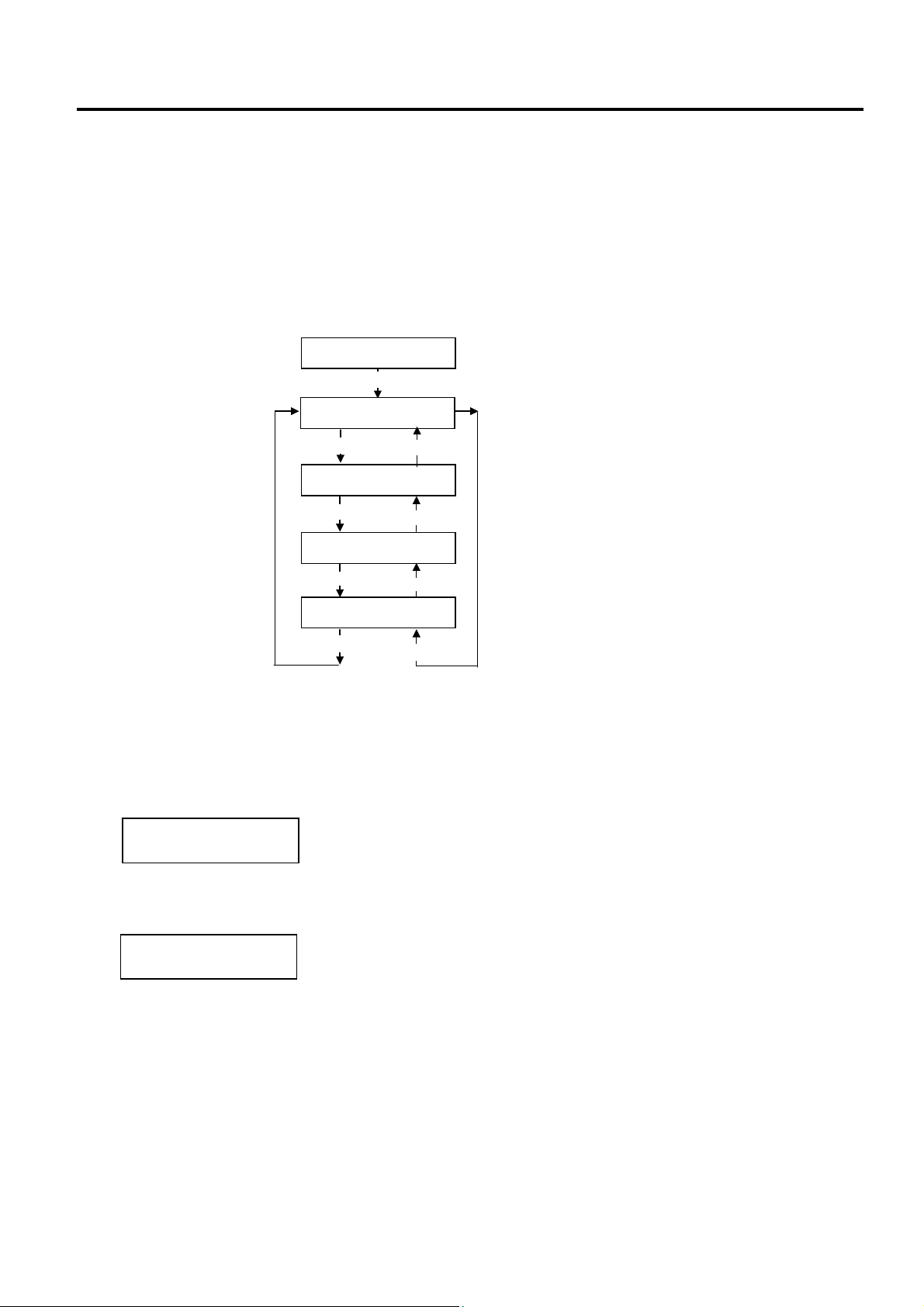
2. SYSTEM MODE EO13-33002
[
[
]
2.8 BASIC Setting
2.8 BASIC Setting
Outline of Basic Setting
The Basic function enables the printer to operate with the program created for other printers, by converting
it to Basic program and downloading this Basic program to the printer. Setting the downloaded Basic
program to be enabled/disabled, browsing the program file, data file, and area file, etc. are available in this
mode. For details, refer to the Basic Interpreter Specification and the Specification of Program Loader for
Basic Interpreter.
The Basic Setting menu contains the following.
How to Enter Basic Setting Mode
<8>BASIC
[PAUSE]
<8>BASIC
BASIC ENABLE
[RESTART]
<8>BASIC
FILE MAINTENANCE
[RESTART]
<8>BASIC
BASIC TRACE
RESTART]
<8>BASIC
EXPAND MODE
[RESTART]
[FEED]
[FEED]
FEED
[FEED]
BASIC Specification Selection Mode
BASIC File Browser
BASIC Trace Selection Mode
Basic Expansion Mode
While pressing the [FEED] and [PAUSE] keys at the same time, turn on the printer. Hold both keys until
the “<1>DIAG. Vx.x” Message appears.
<1>DIAG. Vx.x
Press the [FEED] key until the following display appears.
The printer is at the start of the BASIC setting menu.
<8>BASIC
2-70
Page 77

2. SYSTEM MODE EO13-33002
2.8 BASIC Setting
2.8.1 Basic Specification Selection Mode
This parameter is to choose whether to enable the BASIC specification function or not.
When “<8>BASIC” appears, press the [PAUSE] key.
BASIC ENABLE
BASIC OFF
[PAUSE]
[RESTART] or [FEED]
BASIC ON
FILE MAINTENANCE
[PAUSE]
2.8.2 Basic File Browser
This parameter is to display the data files in the program file and basic file area. Using this function allows
you to check the file names installed in the block.
FILE MAINTENANCE
00 TEST.BAS
01 TEST.DAT
[PAUSE]
Program file is displayed.
[RESTART]
Data file is displayed.
[RESTART]
00 TEST.BAS
[PAUSE]
Data files in the BASIC file area are displayed each time the
[RESTART] key is pressed.
Program file is displayed.
Basic file browser is completed by pressing the [PAUSE] key.
BASIC TRACE
2.8.3 Basic Trace Selection Mode
This parameter is to choose whether to enable the Basic trace function or not.
Usually, this function is set to OFF. When this function is enabled, it will be easier to find an erroneous
program as the program line number are displayed. However, the processing speed of BASIC interpreter
will be slower.
BASIC TRACE
TRACE OFF
[PAUSE]
[RESTART] or [FEED]
[PAUSE]
EXPAND MODE
TRACE ON
Trace specification selection is completed by pressing
the [PAUSE] key.
2-71
Page 78

2. SYSTEM MODE EO13-33002
2.8 BASIC Setting
2.8.4 Basic Expansion Mode (Execution of Basic Program)
This parameter is to execute the Basic expansion mode program.
EXPAND MODE
<8>BASIC
[PAUSE]
When the program for the Basic expansion mode has been
downloaded, it will be executed by pressing the [PAUSE] key.
The way of completion is different depending on the program.
NOTE: In this mode, it is possible to add the program exlucisvely for the B-SX6T/SX8T to the programs for other
printer systems.
2-72
Page 79

2. SYSTEM MODE EO13-33002
A
A
A
A
(Revision Date: Jul. 24, 2008)
2.9 RFID Module Setting
2.9 RFID Module Setting
Outline of the RFID Module Setting
In the RFID Module Setting mode, you can set various parameters related to the RFID module.
It is necessary to set these parameters before operating the RFID module.
If a read or write error occurs frequently, adjust the values for the parameters.
The RFID Module Setting menu contains the following:
<10>RFID
[PAUSE]
<10>RFID
W CYCLE CNT 5
[PAUSE]
Maximum number of write
retries
<10>RFID
READ TEST OFF
[PAUSE]
<10>RFID
MODULE NONE
[PAUSE]
<10>RFID
TAG NONE
[PAUSE]
<10>RFID
ERR CHK OFF
[PAUSE]
<10>RFID
ISSUE RETRY 3
[PAUSE]
<10>RFID
R CYCLE CNT 5
[PAUSE]
<10>RFID
R CYCLE TIM 4.0
[PAUSE]
RFID read test
RFID module type
RFID tag type
RFID error tag detection
Maximum number of issue
retries
Maximum number of read
retries
Read retry time-out
<10>RFID
W CYCLE TIM 2.0
[PAUSE]
<10>RFID
DJ RETRY +00
[PAUSE]
<10>RFID
POWER LEVEL 18
[PAUSE]
<10>RFID
GC THRESHOLD 0
[PAUSE]
<10>RFID
Q VALUE 2
[PAUSE]
<10>RFID
WT AGC 11
[PAUSE]
<10>RFID
WT MIN AGC 11
[PAUSE]
Write retry time-out
RFID adjustment for retry
Radio output power level
setting
RFID AGC threshold setting
RFID Module Q Value Setting
GC threshold for data write
setting
GC threshold lower limit for
retry setting
2-73
Page 80

2. SYSTEM MODE EO13-33002
t
A
(Revision Date: Mar. 26, 2009)
2.9 RFID Module Setting
How to Enter RFID Module Setting Mode
Turn on the printer while pressing the [FEED] and [PAUSE] keys at the same time. Hold both keys until the
“<1>DIAG. Vx.x” Message appears.
<1>DIAG. Vx.x
Press the [RESTART] key or [FEED] key until “<10>RFID” appears.
2.9.1 RFID Read Test
This parameter is to choose whether to perform an RFID read test. When using an RFID module for the
first time, or when performing an RFID read test after performing a parameter clear, it is necessary to set
the RFID module parameters in advance. Refer to Section 2.9.2.
When “<10>RFID” appears, press the [PAUSE] key.
<10>RFID
READ TEST OFF
[PAUSE]
The next menu will appear withou
performing a read test. Refer to
Section 2.9.2.
<Read Test Procedure>
1) Place a TOSHIBA-recommended RFID tag as close as the antenna.
NOTE: Available RFID tag
B-SX708-RFID-U2-EU-R, B-SX708-RFID-U2-CN-R: EPC C1 Gen2
2) The printer enters the read test mode, and a read test is performed each time the [PAUSE] key is
pressed. The read data on the tag is displayed on the LCD message display. If the tag cannot be
read, “RFID TIMEOUT” or “RFID READ ERROR” is displayed. Only the tags selected by the RFID
tag type selection can be read. An RFID tag read error will result if the type of the tag to be read and
the type of the tag selected by the RFID tag type selection do not match. Make sure the RFID tag
type has been selected before the read test is started.
Example (Q value = 0)
1234567890123456
6543210987654321
Example (Q value = 1)
1234567890123456
65432109 (0E)
The data, displayed in hex. numbers. Displayed data is an EPC code in the EPC area.
When the RFID tag contains data of 16 digits or more, the first 16 digits are displayed. When data
volume is less than 16 digits, the vacant digits will be filled with spaces.
In the case the Q value is set to 1 or greater, the AGC value of a read tag, enclosed with
parentheses, is displayed on the right most place on the lower line. Therefore, 14-byte data is
displayed in hex. code.
Additionally, if more than one tag is read at one time, especially when short-pitch tags are used,
pressing the [FEED] or [RESTART] key shows the other tags’ data. Among them, a tag with the
highest AGC value is considered to be positioned just above the antenna.
[FEED] or [RESTART]
<10>RFID
READ TEST ON
[PAUSE]
A read test will be performed.
s this read test is intended to just read a tag, if you
would like to perform a write test, use RFID Analyse
Tool. Refer to Section 5.
2-74
Page 81
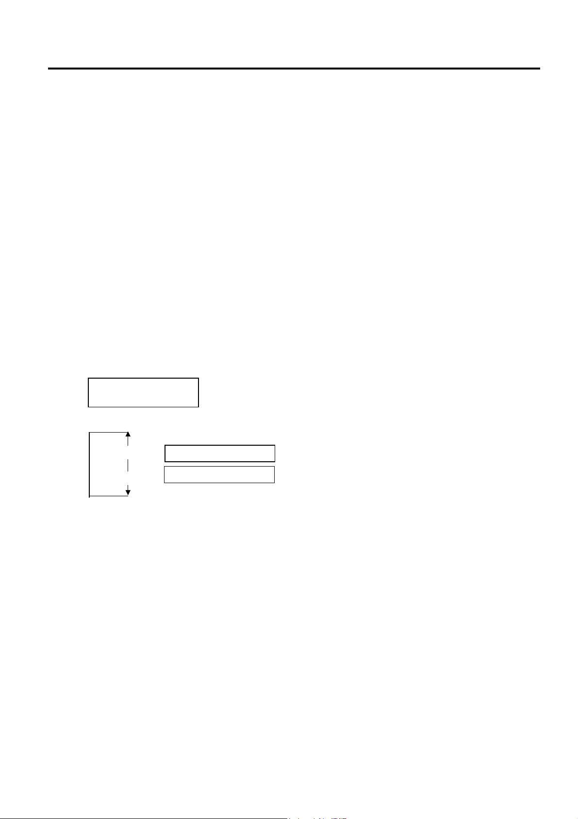
2. SYSTEM MODE EO13-33002
(Revision Date: Mar. 26, 2009)
2.9 RFID Module Setting
When the RFID module type is set to “NONE” or a communication cannot be established, a
message, “NON RFID MODULE”, is displayed.
“NO RFID MODULE”, “TIMEOUT” or “RFID READ ERROR” indicates an error. In that case, check
the following:
• In case of NO RFID MODULE
- Connection failure of the antenna cable ⇒ Check the connection.
- Connection failure of the interface cable ⇒ Check the connection.
- Wrong parameter setting ⇒ Check the parameter setting.
• In case of TIMEOUT or RFID READ ERROR
- The RFID tag used is hard to read. ⇒ Refer to the Product Description and check the available
RFID tag types.
- TOSHIBA-recommended tag is not used. ⇒ Refer to the Product Description and check the
available RFID tag types. Increase the value for R CYCLE CNT or R CYCLE TIM
3) In case a test succeeded, a read test will be performed each time the [PAUSE] key is pressed.
4) To finish a read test, turn off the printer.
2.9.2 RFID Module Type Selection
This parameter is to choose an RFID module type to be used. Improper choice will disable the RFID
module. The initial setting (including the status after a parameter clear) is “MODULE NONE”.
When “MODULE NONE” is displayed, press the [PAUSE] key.
Use the [FEED] or [RESTART] key to select a desired option.
NOTE: This parameter setting is effective when turning OFF then ON the printer.
After selecting the RFID module type to be used, press the [PAUSE] key.
<10>RFID
MODULE NONE
[RESTART]
[FEED]
MODULE NONE RFID module is not used. (default)
MODULE U2
B-SX708-RFID-U2-EU-R or B-SX708-RFID-U2-CN-R is
installed.
2-75
Page 82

2. SYSTEM MODE EO13-33002
(Revision Date: Mar. 26, 2009)
2.9 RFID Module Setting
2.9.3 RFID Tag Type Selection
This parameter is to choose an RFID tag type to be used. Available tag type is different depending on the
RFID module type.
When the RFID Module Type has been set to NONE
Use the [FEED] or [RESTART] key to select a desired option.
After selecting the RFID tag type to be used, press the [PAUSE] key.
NOTE: Combination of RFID module type and available tag type
<10>RFID
TAG NONE
[RESTART]
[FEED]
Tag type Parameter for TPCL command RFID module type
NONE 00
EPC C1 Gen2 24
TAG NONE
TAG EPC C1 Gen2
B-SX708-RFID-U2-EU-R, B-SX708-RFID-CN-R
2.9.4 RFID Error Tag Detection
This parameter is to choose whether an error detection is performed or not before writing data on an RFID
tag. When “ON” is selected, data is written on an RIFD only when no error is detected.
NOTE: This function is exclusively for Alien’s EPC CI Squiggle tag. Choose “OFF” usually.
When “ERR CHK OFF” is displayed, press the [PAUSE] key.
<10>RFID
ERR CHK OFF
Use the [FEED] or [RESTART] key to select a desired option.
[RESTART]
ERR CHK OFF
[FEED]
ERR CHK ON
Error tag detection is not performed. A tag is read before
writing data on it, but data is always written regardless of
the header data of the tag.
Error tag detection is performed. (Only when the header
data of the RFID data is “A5A5”, data is written on the
RFID tag. This function is available only for Alien’s EPC CI
Squiggle tag only.)
After selecting the RFID error tag detection function to be used, press the [PAUSE] key.
2-76
Page 83

2. SYSTEM MODE EO13-33002
(Revision Date: Jul. 24, 2008)
2.9 RFID Module Setting
2.9.5 Maximum Number of RFID Issue Retries
This parameter is to set the maximum number of times to issue an RFID tag. If the printer fails to issue an
RFID tag, it prints an error pattern (“VOID”) and retries to issue the tag for up to a specified number of times.
If the printer does not succeed even after having retried for the maximum number of times, the printer stops,
resulting in an error (RFID WRITE ERROR).
When “ISSUE RETRY 3” is displayed, press the [PAUSE] key.
<10>RFID
ISSUE RETRY 3
Use the [FEED] or [RESTART] key to select a desired option. (Range: 0 to 255)
ISSUE RETRY 255
[RESTART]
[FEED]
ISSUE RETRY 3
ISSUE RETRY 2
ISSUE RETRY 1
ISSUE RETRY 0
[FEED] key: Pressing the [FEED] key one time causes a –1 change, up to 0.
[RESTART] key: Pressing the [RESTART] key one time causes a +1 change, up to 255.
After selecting the maximum number of issue retries, press the [PAUSE] key.
2-77
Page 84

2. SYSTEM MODE EO13-33002
(Revision Date: Jul. 24, 2008)
2.9 RFID Module Setting
2.9.6 Maximum Number of RFID Read Retries
This parameter is to set the maximum number of times to read an RFID tag.
If the printer does not succeed even if after having retried for the maximum number of times, the printer
stops, resulting in an error (TIMEOUT). In case of frequent read errors, increase this retry count. However,
when the retry count is increased, a data read may become slower.
If the specified time-out runs out, the printer stops retry even before the maximum number of retry times is
reached. The printer always reads an RFID tag for a maximum number of retry times set by this parameter
before writing data to the RFID.
When “R CYCLE CNT 5” is displayed, press the [PAUSE] key.
Use the [FEED] or [RESTART] key to select a desired option. (Range: 0 to 255)
[FEED] key: Pressing the [FEED] key one time causes a –1 change, up to 0.
[RESTART] key: Pressing the [RESTART] key one time causes a +1 change, up to 255.
After selecting the maximum number of read retries, press the [PAUSE] key.
<10>RFID
R CYCLE CNT 5
R CYCLE CNT 255
[RESTART]
R CYCLE CNT 3
R CYCLE CNT 2
[FEED]
R CYCLE CNT 1
R CYCLE CNT 0
2-78
Page 85

2. SYSTEM MODE EO13-33002
(Revision Date: Jul. 24, 2008)
2.9 RFID Module Setting
2.9.7 RFID Read Retry Time-out
This parameter is to set the time-out for retry to read an RFID tag.
If the printer does not succeed within the specified time-out, the printer stops, resulting in an error
(TIMEOUT). In case of frequent read errors, increase the amount of time. However, when the amount of
time is increased, a data read may become slower.
If the maximum number of retries is reached, the printer stops retry even before the specified time runs out.
The printer always reads an RFID tag for the specified time set by this parameter before writing data to the
RFID.
When “R CYCLE TIM 4.0” is displayed, press the [PAUSE] key.
Use the [FEED] or [RESTART] key to select a desired option. (Range: 0.0 sec. to 9.9 sec.)
[FEED] key: Pressing the [FEED] key one time causes a –0.1 change, up to 0.0.
[RESTART] key: Pressing the [RESTART] key one time causes a +0.1 change, up to 9.9.
After selecting the time-out, press the [PAUSE] key.
<10>RFID
R CYCLE TIM 4.0
R CYCLE TIM 9.9
[RESTART]
R CYCLE TIM 4.0
R CYCLE TIM 3.9
[FEED]
R CYCLE TIM 0.0
2-79
Page 86
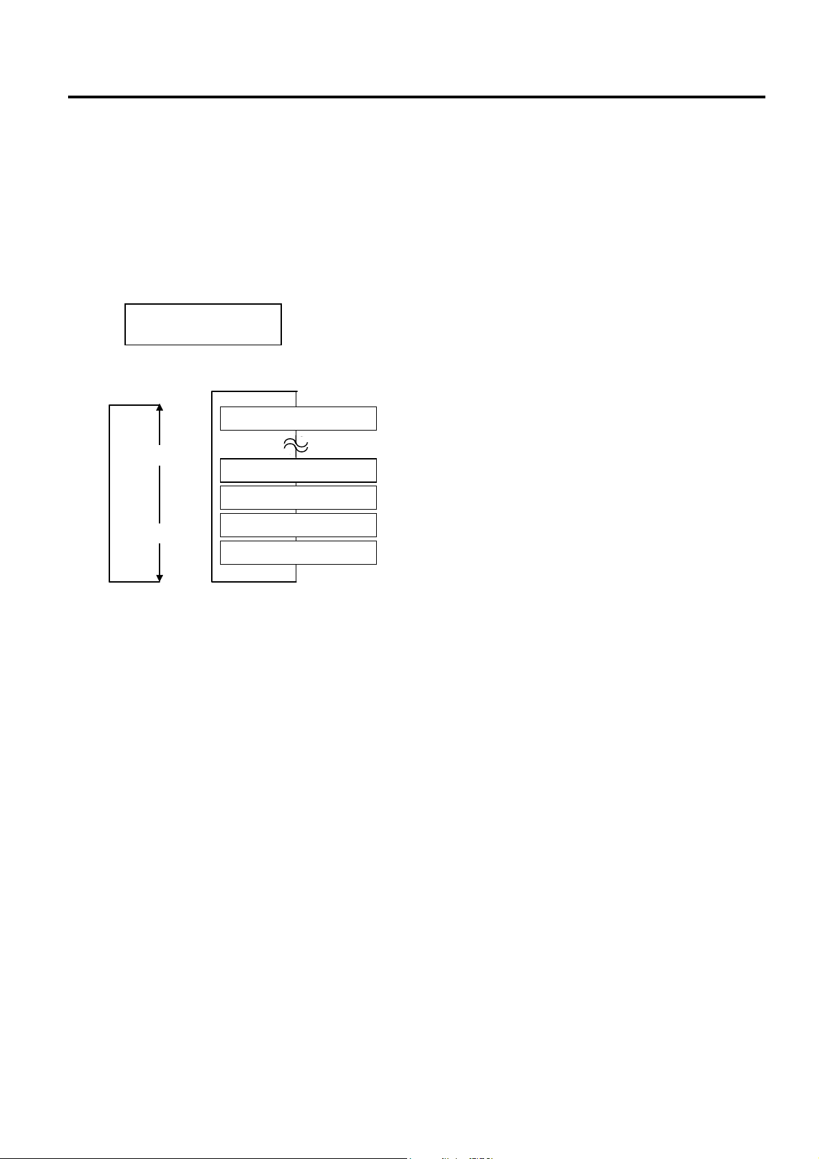
2. SYSTEM MODE EO13-33002
(Revision Date: Jul. 24, 2008)
2.9 RFID Module Setting
2.9.8 Maximum Number of RFID Write Retries
This parameter is to set the maximum number of times to write data onto an RFID tag.
If the printer does not succeed even if after having retried for the maximum number of times, the printer
stops, resulting in an error (RFID WRITE ERROR). In case of frequent write errors, increase this retry
count. However, when the retry count is increased, writing data may become slower.
If the specified time-out runs out, the printer stops retry even before the maximum number of retry times is
reached.
When “W CYCLE CNT 5” is displayed, press the [PAUSE] key.
Use the [FEED] or [RESTART] key to select a desired option. (Range: 0 to 255)
[FEED] key: Pressing the [FEED] key one time causes a –1 change, up to 0.
[RESTART] key: Pressing the [RESTART] key one time causes a +1 change, up to 255.
After selecting the maximum number of write retries, press the [PAUSE] key.
<10>RFID
W CYCLE CNT 5
W CYCLE CNT 255
[RESTART]
W CYCLE CNT 3
W CYCLE CNT 2
[FEED]
W CYCLE CNT 1
W CYCLE CNT 0
2-80
Page 87

2. SYSTEM MODE EO13-33002
(Revision Date: Jul. 24, 2008)
2.9 RFID Module Setting
2.9.9 RFID Write Retry Time-out
This parameter is to set the time-out for retry to write data onto an RFID tag.
If the printer does not succeed within the specified time-out, the printer stops, resulting in an error
(TIMEOUT). In case of frequent read errors, increase the amount of time. However, when the amount of
time is increased, a data read may become slower.
If the maximum number of retries is reached, the printer stops retry even before the specified time runs out.
The printer always reads an RFID tag for the specified time set by this parameter before writing data to the
RFID.
When “W CYCLE TIM 2.0” is displayed, press the [PAUSE] key.
Use the [FEED] or [RESTART] key to select a desired option. (Range: 0.0 sec. to 9.9 sec.)
[FEED] key: Pressing the [FEED] key one time causes a –0.1 change, up to 0.0.
[RESTART] key: Pressing the [RESTART] key one time causes a +0.1 change, up to 9.9.
After selecting the time-out, press the [PAUSE] key.
<10>RFID
W CYCLE TIM 2.0
W CYCLE TIM 9.9
[RESTART]
W CYCLE TIM 2.0
W CYCLE TIM 1.9
[FEED]
W CYCLE TIM 0.0
2-81
Page 88

2. SYSTEM MODE EO13-33002
A
A
(Revision Date: Jul. 24, 2008)
2.9 RFID Module Setting
2.9.10 RFID Adjustment for Retry
If the printer fails to write data to an RFID tag, it feeds the RFID tag forward or backward for a specified
length, then starts retrying to write data. If “0” is set for this parameter, however, a feed or a reverse feed of
the RFID tag is not performed.
As a write error may be caused by a misalignment of an RFID tag and the antenna, adjust the RFID tag
position so that it stops just above the antenna.
Please obtain a value to be set for this parameter by using an RFID Analyze Tool (See Section 5.)
When “ADJ RETRY +00” is displayed, press the [PAUSE] key.
Use the [FEED] or [RESTART] key to select a desired option. (Range: -99mm to +99mm)
[FEED] key: Pressing the [FEED] key one time causes a –1mm change, up to –99mm.
[RESTART] key: Pressing the [RESTART] key one time causes a +1mm change, up to +99mm.
• Adjustment in negative (−) direction
• Adjustment in positive (+) direction
After selecting the adjustment value, press the [PAUSE] key.
<10>RFID
ADJ RETRY +00
ADJ RETRY +99
[RESTART]
ADJ RETRY +01
ADJ RETRY +00
[FEED]
ADJ RETRY -99
ntenna
RFID Tag
RFID Tag
ntenna
Feed Direction
Feed Direction
2-82
Page 89

2. SYSTEM MODE EO13-33002
(Revision Date: Jul. 24, 2008)
2.9 RFID Module Setting
2.9.11 RFID Wireless Power Level Setting
With this parameter, it is possible to adjust the level of radio frequency output from the RFID module.
The optimum level differs depending on the tag types and module types.
First, try issuing RFID tags with the default setting. If an error frequently occurs, adjust the output level.
When “POWER LEVE” is displayed, press the [PAUSE] key. (Default is 18.)
Use the [FEED] or [RESTART] key to select a desired option. (Range: 9 to 18)
After selecting the adjustment value, press the [PAUSE] key. The display returns to “<10>RFID”.
<10>RFID
POWER LEVEL 18
POWER LEVEL 18
[RESTART]
[FEED]
POWER LEVEL 17
POWER LEVEL 10
POWER LEVEL 9
High level
Low level
NOTE: The optimal value is different depending on the tags used. Usually it is not necessary to change
this value but changing the value sometimes can increase the number of successful read/write
times.
2.9.12 RFID AGC Threshold
This parameter is to set a threshold used to identify an RFID tag is defective or not.
When the obtained gain of an RFID tag is lower than the AGC threshold, the tag is considered as an error tag
even if a data write succeeds.
When the AGC threshold is set to “0”, all tags are writable.
When set to “8”, for example, only tags with the AGC threshold level of 9 or greater are writable. The optimum
value is different depending on the tag types. The factory default is 0.
Set an AGC threshold with the [FEED] or [RESTART] key.
When “AGC THRESHOLD” is displayed, press the [PAUSE] key.
Use the [FEED] or [RESTART] key to select a desired option. (Range: 0 to 15)
After selecting the adjustment value, press the [PAUSE] key.
<10>RFID
AGC THRESHOLD 0
AGC THRESHOLD 15
[RESTART]
[FEED]
AGC THRESHOLD 14
AGC THRESHOLD 1
AGC THRESHOLD 0
2-83
Page 90

2. SYSTEM MODE EO13-33002
(Revision Date: Jul. 24, 2008)
2.9 RFID Module Setting
2.9.13 RFID Module Q Value Setting
This parameter is to set the Q value.
In the case multiple RFID tags are read at the same time, this menu is useful to pinpoint a target tag.
Set the Q value to “1” or greater (2 is recommended.) with the [FEED] or [RESTART] key. Q value “0”
causes the tags to interfere with each other and disables proper data write.
When a Q value is set, set an AGC threshold for data write and an AGC threshold lower limit for retry, also.
Setting all these values enable writing data to a tag placed just above the antenna. (For details, refer to
Section 8.5 of Option Installation Manual) The factory default is 0.
When “Q VALUE” is displayed, press the [PAUSE] key.
Use the [FEED] or [RESTART] key to select a desired option. (Range: 0 to 15)
After selecting the adjustment value, press the [PAUSE] key.
<10>RFID
Q VALUE 2
[RESTART]
[FEED]
QVALUE 15
QVALUE 14
QVALUE 1
QVALUE 0
2-84
Page 91
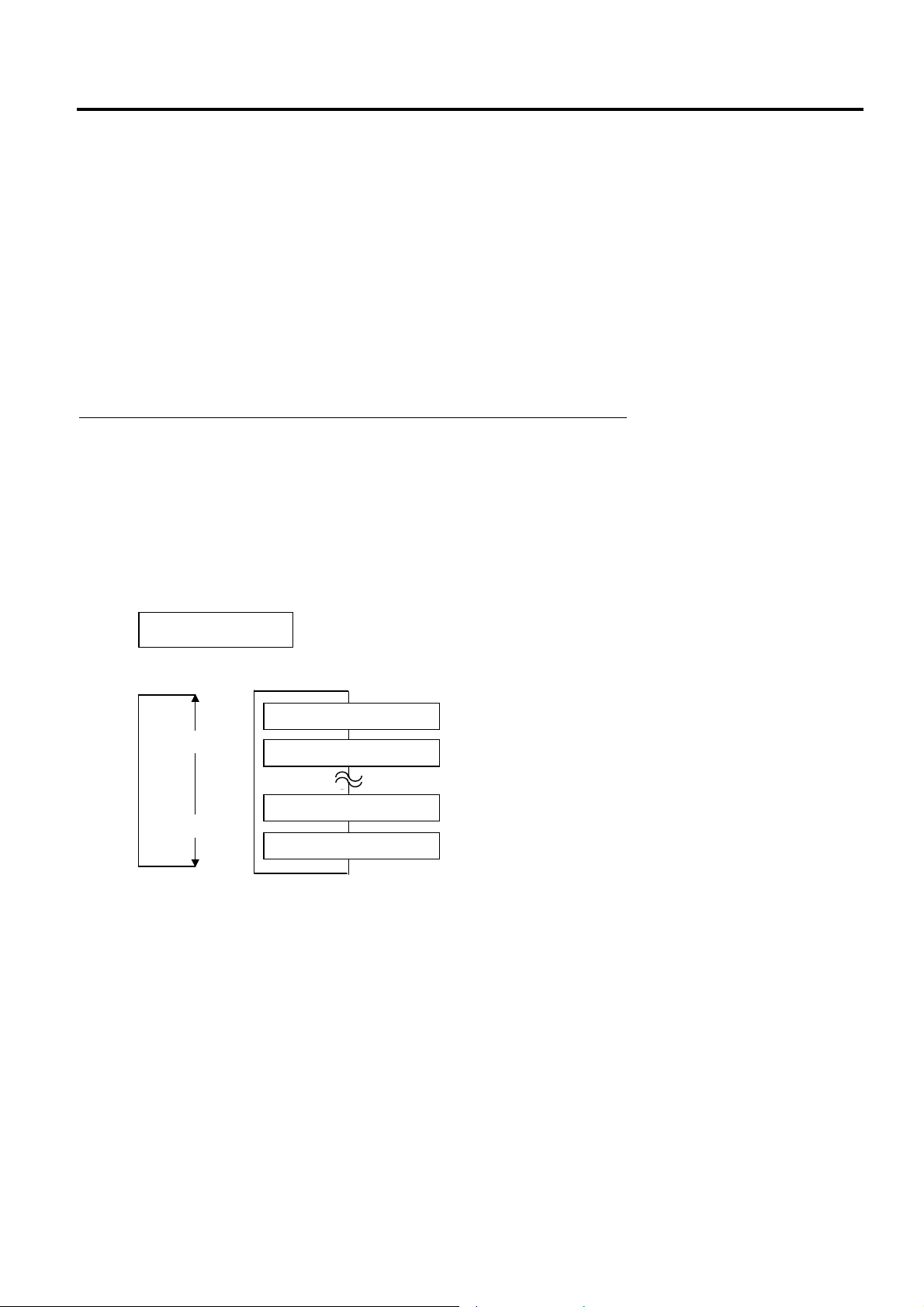
2. SYSTEM MODE EO13-33002
(Revision Date: Jul. 24, 2008)
2.9 RFID Module Setting
2.9.14 AGC Threshold for Data Write Setting
This parameter is to set the AGC threshold for data write.
When the Q value is set to 1 or greater, the AGC threshold for data write becomes effective.
When the obtained gain of an RFID tag is lower than the AGC threshold for data write, a data write
operation is not performed. In other words, setting an AGC threshold for data write enables writing data
only to a tag placed just above the antenna.
Supposing that the gain of a tag just above the antenna is 14 and that of a tag off the antenna is 7, setting
the threshold to 11 (a value between 8 and 14) enables the printer to write data only to the tag just above
the antenna.
When the threshold is set to 0, a data write operation is performed regardless of the gain of a tag.
The optimum value differs depending on the tag type. (For details, refer to Section 8 of Option Installation
Manual.)
Difference between the AGC threshold and the AGC threshold for data write
Both of the AGC threshold and the AGC threshold for data write are used to determine whether a tag is
defective or not, but the timing of a gain measurement is different. In the case of the AGC threshold, this is
performed after data is written to a tag.
On the contrary, when the AGC threshold for data write is effective a measurement is performed before
data is written. And if a gain value is lower than the threshold, a data write operation is not performed.
Set an AGC threshold for data write with the [FEED] or [RESTART] key, if necessary.
When “WT AGC” is displayed, press the [PAUSE] key.
<10>RFID
WT AGC 11
Use the [FEED] or [RESTART] key to select a desired option. (Range: 0 to 15)
[RESTART]
WT AGC 15
WT AGC 14
[FEED]
WT AGC 1
WT AGC 0
After selecting the adjustment value, press the [PAUSE] key.
2-85
Page 92
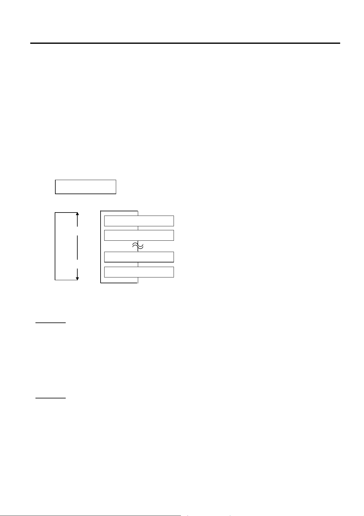
2. SYSTEM MODE EO13-33002
(Revision Date: Jul. 24, 2008)
2.9 RFID Module Setting
2.9.15 AGC Threshold Lower Limit for Retry Setting
This parameter is to set an AGC threshold lower limit.
When the Q value is set to 1 or greater, the AGC threshold lower limit for retry becomes effective.
Even if a tag’s gain is lower than the AGC threshold for data write, a data write to the tag may be successful
in a retry if the gain is greater than the lower limit. For a retry, the printer lowers the threshold to the highest
gain of the tag if it is greater than the lower limit or to the lower limit if it is greater than the highest gain of
the tag. (For details, refer to Section 8 of Option Installation Manual.)
When the same value is set to the AGC threshold for data write and the AGC threshold lower limit for retry,
respectively, the threshold will not be changed for a retry.
The optimum value differs depending on the tag type.
Set the lower limit for retry with the [FEED] or [RESTART] key, if necessary.
When “WT MIN AGC” is displayed, press the [PAUSE] key.
Use the [FEED] or [RESTART] key to select a desired option. (Range: 0 to 15)
After selecting the adjustment value, press the [PAUSE] key. The display returns to “<10>RFID”.
<10>RFID
WT MIN AGC 11
[RESTART]
[FEED]
WT MIN AGC 15
WT MIN AGC 14
WT MIN AGC 1
WT MIN AGC 0
Note:
Example 1
AGC threshold for data write: 11
Lower limit for retry: 9
Detected tag’s gain: 10
As the gain of the tag is lower than the threshold, a data write operation is not performed for this tag at the first
try. However, the gain is greater than the lower limit.
Then the printer retires to write data to this tag according to a new AGC threshold of 10.
In this case, a retry of a data write will mostly succeed because the detected tag’s gain is greater than the new
threshold. (However, the success rate is not 100% because a gain of a tag is not always the same.)
Example 2
AGC threshold for data write: 11
Lower limit for retry: 9
Detected tag’s gain: 8
As the gain of the tag is lower than the threshold, a data write operation is not performed for this tag at the first
try. Also, the gain is lower than the lower limit.
Then the printer retries to write data to this tag according to a new AGC threshold of 9.
In this case, a retry of data write will mostly fail because the detected tag’s gain is lower than the new threshold.
(However, the error rate is not 100% because a gain of a tag is not always the same.)
2-86
Page 93

3. ON LINE MODE EO13-33002
3. ON LINE MODE
3. ON LINE MODE
In the ON LINE mode, the following settings can be performed.
• Automatic threshold setting for the Feed Gap Sensor
• Automatic threshold setting for the Black Mark Sensor
• Reset
• Parameter settings (Same as Section 2.2.)
• Printer parameter fine adjustment (Same as Section 2.3.)
• Dump mode
• Expansion mode
• Automatic calibration
• Enabling/disabling the LAN
• Real time clock setting
This section describes the automatic threshold setting for the feed gap sensor/black mark sensor, reset
operation, dump mode, automatic calibration, LAN setting, and real time clock setting. The procedures of
the parameter setting and printer parameter fine adjustment are described in Section 2.2 and Section 2.3
respectively.
ON LINE
[PAUSE]
PAUSE
Hold down [PAUSE]
key for 3 sec.
Hold down [RESTART] key for 3 sec.
<1>RESET
[FEED] [RESTART]
<2>PARAMETER SET
[FEED] [RESTART]
<3>ADJUST SET
[FEED] [RESTART]
<4>DUMP MODE
[FEED] [RESTART]
[PAUSE]
[PAUSE]
[PAUSE]
[PAUSE]
TRANSMISSIVE
Automatic threshold setting
for the feed gap sensor
[FEED] or[RESTART]
REFLECTIVE
Automatic threshold setting
for the black mark sensor
Reset operation menu
Parameter setting menu (Refer to Section 2.2.)
Printer Parameter fine adjustment menu (Refer to Section 2.3.)
Dump mode menu
<5>EXPAND MODE
[FEED] [RESTART]
<6>AUTO CALIB.
[FEED] [RESTART]
<7>LAN
[FEED] [RESTART]
<8>RTC SET
[FEED]
[RESTART]
[PAUSE]
[PAUSE]
[PAUSE]
[PAUSE]
BASIC expansion menu
Automatic calibration setting menu
LAN enable/disable setting menu
Real Time Clock setting menu
3- 1
Page 94

3. ON LINE MODE EO13-33002
t
A
3. ON LINE MODE
LCD message and LED indication
Symbols in the message
1: : The LED is illuminated. ~: The LED is flashing. z: The LED is unlit.
2: ****: the number of unprinted media. Up to 9999 (in pieces)
3: ###: Flash memory card remaining memory for PC save area: 0 to 3072 (in K bytes)
4: &&&&: Remaining flash memory capacity for storing writable characters 0 to 3072 (in K bytes)
LED Indication
No. LCD Message
ON LINE z Online mode ----- Yes
1
ON LINE
POWER
ON
ERROR
LINE
~ z Online mode (communicating) ----- Yes
Printer Status
Restoration
by
RESTART
key Yes/No
Acceptance of
Status Reques
Reset
Command
Yes/No
2 HEAD OPEN z z The Top Cover is opened in online mode. ----- Yes
3 PAUSE **** z z Pause state Yes Yes
4 COMMS ERROR z
A parity, overrun, or framing error has
occurred during a communication by
Yes Yes
RS-232C.
5 PAPER JAM **** z
6 CUTTER ERROR**** z
7 NO PAPER **** z
A paper jam has occurred during paper
feed.
A problem has occurred at the cutter
module.
The media has run out, or the media is
not loaded properly.
Yes Yes
Yes Yes
Yes Yes
8 NO RIBBON **** z The ribbon has run out. Yes Yes
9 HEAD OPEN **** z
feed or an issue was attempted with the
Top Cover opened. (Except when the
Yes Yes
[FEED] key is pressed.)
10 HEAD ERROR z The print head has a problem. Yes Yes
11 EXCESS HEAD TEMP z The print head is overheated. No Yes
12 RIBBON ERROR**** z
The ribbon has been torn. A problem
has occurred with the sensor that
determines the torque for the ribbon
Yes Yes
motor.
13 SAVING ####&&&& z
14 FLASH WRITE ERR. z
15 FORMAT ERROR z
16 FLASH CARD FULL z
Display of error
17
message (See Note.)
z
In writable character or PC command
save mode
An error has occurred in writing to the
flash ROM.
An error has occurred in formatting the
flash ROM.
Saving failed because of an insufficient
capacity of the flash ROM.
A command error has occurred in
analyzing the command.
----- Yes
No Yes
No Yes
No Yes
Yes Yes
18 POWER FAILURE z A momentary power failure has occurred. No No
19 INTIALIZING… z z The flash ROM is being initialized. ----- -----
20 EEPROM ERROR z
Data cannot be read from/written to a
backup EEPROM properly.
----- -----
3- 2
Page 95

3. ON LINE MODE EO13-33002
t
(Revision Date: Jul. 24, 2008)
3. ON LINE MODE
Acceptance of
Status Reques
Reset
Command
Yes/No
No. LCD Message
LED Indication
POWER
ON
LINE
ERROR
Printer Status
When the following abnormal operations
Restoration
by
RESTART
key Yes/No
No No
are performed, a system error occurs:
(a) Command fetch from an odd
address
(b) Access to word data at an odd
address
(c) Access to long-word data at an odd
address
21 SYSTEM ERROR z
(d) Access to the area of 80000000H to
FFFFFFFFH in the logic space in
user mode.
(e) An undefined instruction in an area
other than a delay slot was decoded.
(f) An undefined instruction in a delay
slot was decoded.
(g) An instruction to rewrite a delay slot
was decoded.
100BASE LAN
22
INITIALIZING…
DHCP CLIENT
23
INITIALIZING…
24 LOW BATTERY z
25 RFID WRITE ERROR z
26 RFID ERROR z
z z
z z
100 Base LAN Board is being initialised. ----- -----
The DHCP client is being initialized.
*When the DHCP function is enabled.
The voltage of the Real Time Clock Battery is
1.9V or less.
The printer did not succeed in writing data
onto an RFID tag after having retried for a
specified times.
The printer cannot communicate with the
RFID module.
----- -----
No Yes
Yes Yes
No Yes
NOTE: Description of Command Error
• If a command error is found in a command received, 16 bytes of the command error, starting from the command
code, will be displayed. (However, [LF] and [NUL] will not be displayed.)
Example 1 Example 2
[ESC] T20 G
30 [LF] [NUL] [ESC] XR; 0200, 0300, 0450, 1200, 1, [LF] [NUL]
Command error Command error
The following message appears. The following message appears.
T20G30
B-SX8T V1.0A
XR;0200,0300,045
B-SX8T V1.0A
Example 3
[ESC] PC001; 0A
00, 0300, 2, 2, A, 00, B [LF] [NUL]
Command error
XR;0200,0300,045
B-SX8T V1.0A
The following message appears.
PC001;0A00,0300,
B-SX8T V1.0A
• When the error command is shown, “? (3FH)” appears for codes other than codes 20H to 7FH and A0H to DFH.
• For details, please refer to the B-SX6T/SX8T Series External Equipment Interface Specification.
3- 3
Page 96

3. ON LINE MODE EO13-33002
y
3.1 Automatic Threshold Setting
3.1 Automatic Threshold Setting
Outline of Automatic Threshold Setting
To maintain a constant print position the printer uses the media sensor to detect a print start position
according to the difference of voltage between a print area and a gap or black mark. When the media is
pre-printed, the darker (or more dense) inks can interfere with this process, causing “PAPER JAM” errors
even if the media is not actually jammed.
To get around this problem, first, try an automatic threshold setting.
If the problem still occurs, then, the threshold voltage needs to be manually set. (Refer to Section 2.3.7.)
How to Perform an Automatic Threshold Setting
Load pre-printed media in the printer.
NOTES: 1. Failure to feed more than 1.5 labels may result in an incorrect threshold setting.
2. While the Top Cover is raised, the [PAUSE] key does not work.
ON LINE
B-SX8T Vx.x
[PAUSE]
PAUSE
B-SX8T Vx.x
Press and hold the [PAUSE] ke
for 3 seconds or longer.
TRANSMISSIVE
B-SX8T Vx.x
Press and hold the [PAUSE]
key until more than 1.5 labels
(tags) have been fed.
PAUSE
B-SX8T Vx.x
[RESTART]
ON LINE
B-SX8T Vx.x
[FEED]
[RESTART]
REFLECTIVE
B-SX8T Vx.x
Press and hold the [PAUSE]
key until more than 1.5 labels
(tags) have been fed.
During this media feed,
a threshold is
automatically set.
3- 4
Page 97

3. ON LINE MODE EO13-33002
3.2 Reset Operation
3.2 Reset Operation
A reset operation clears the print data sent from the host computer to the printer, and returns the printer to an
idle condition.
How to Perform a Reset Operation
NOTE: Failure to press the [RESTART] key for 3 seconds or longer causes the printer to restart printing.
ON LINE
B-SX8T Vx.x
[PAUSE]
PAUSE 52
B-SX8T Vx.x
Press and hold the [RESTART]
key for 3 seconds or longer.
<1>RESET
[PAUSE]
ON LINE
B-SX8T Vx.x
However, when a communication error or command error occurs, the printer returns to an idle state.
Press the [PAUSE] key to stop printing
The number of remaining print count
NOTE: When the [PAUSE] key is pressed during printing, the
number of remaining print count is displayed.
Data sent from the host computer is cleared.
3- 5
Page 98

3. ON LINE MODE EO13-33002
f
A
(Revision Date: Jul. 24, 2008)
3.3 Dump Mode
3.3 Dump Mode
In dump mode, data in the receive buffer are printed. Data are expressed in hexadecimal values. This
operation allows the user to verify programming commands or debug the program.
How to Perform a Dump Operation
ON LINE
B-SX8T Vx.x
[PAUSE]
PAUSE 52
B-SX8T Vx.x
Press and hold the [RESTART]
key for 3 seconds or longer.
<1>RESET
Press the [FEED] key until
<4>DUMP MODE is displayed.
<4>DUMP MODE
[PAUSE]
<4>DUMP MODE
BUFFER RS-232C
[FEED] or [RESTART]
[PAUSE]
<4>DUMP MODE
PRINT ON DEMAND
[FEED] or [RESTART]
*
<4>DUMP MODE
NOW PRINTING…
<4>DUMP MODE
[PAUSE]
Press the [PAUSE] key to stop printing.
The number of remaining print count
NOTE: When the [PAUSE] key is pressed during printing, the number o
remaining print count is displayed.
Press the [PAUSE] key to enter the dump mode.
Choose a receive buffer to be dumped using the [FEED] or [RESTART]
key.
• RS-232C: RS-232C receive buffer
• CENTRO: Centronics receive buffer
• NETWORK: Network interface receive buffer
• BASIC 1: BASIC interpreter (Interface → Interpreter buffer)
• BASIC 2: BASIC interpreter (Interpreter → Printer buffer)
• USB: USB receive buffer
• RF-ID: RFID receive buffer
Choose a printing method using the [FEED] or [RESTART] key.
• ON DEMAND: Prints 166 lines of data (approx. 50cm), then stops.
* To print the subsequent data, choose a printing method
again and press the [PAUSE] key.
• ALL: Prints all data in the receive buffer, then stops.
The printer starts printing data in the receive buffer.
fter all data has been printed, the display returns to <4>DUMP MODE.
Turn the power off, and then on.
ON LINE
B-SX8T Vx.x
3- 6
Page 99

3. ON LINE MODE EO13-33002
(Revision Date: Jul. 24, 2008)
3.3 Dump Mode
The data in the receive buffer is printed as follows:
00 00 00 00 00 00 00 00 00 00 00 00 00 00 00 00
00 00 00 00 00 00 00 00 00 00 00 00 00 00 00 00
00 00 00 00 00 00 00 00 00 00 00 00 00 00 00 00
7B 41 58 3B 2B 30 30
30 7C 7D 7B 44 30 37 37 30 2C 31 31 30 30 2C 30 0|}{D0760,1100,0
37 34 30 7C 7D 7B 43 7C 7D 7B 4C 43 3B 30 30 33 740|}{C|}{LC;003
30 2C 30 30 32 30 2C 30 30 33 30 2C 30 36 36 30 0,0020,0030,0660
2C 30 2C 32 7C 7D 7B 4C 43 3B 30 30 37 30 2C 30 ,0,2|}{LC;0070,0
30 32 30 2C 30 30 37 30 2C 30 36 36 30 2C 30 2C 020,0070,0660,0,
39 7C 7D 7B 4C 43 3B 30 30 35 30 2C 30 30 32 30 9|}{LC;0050,0020
44 45 46 47 48 49 4A 7C 7D 7B 50 43 31 30 3B 30 DEFGHIJ|}{PC10;0
33 35 30 2C 30 34 30 30 2C 31 2C 31 2C 4B 2C 30 350,0400,1,1,K,0
30 2C 42 3D 41 42 43 44 65 66 67 68 69 6A 6B 6C 0,B=ABCDefghijkl
6D 6E 6F 70 7C 7D 7B 50 56 30 32 3B 30 33 33 30 mnop|}{PV02;0330
2C 30 36 36 30 2C 30 32 37 30 2C 30 32 35 30 2C ,0660,0270,0250,
41 2C 30 30 2C 42 3D 42 7C 7D 7B 50 56 30 33 3B A,00,B=B|}{PV03;
3B 30 39 30 30 2C 30 31 38 30 2C 54 2C 48 2C 30 ;0900,0180,T,H,0
35 2C 41 2C 30 3D 31 32 33 34 35 36 37 38 39 30 5,A,0=1234567890
41 42 43 44 45 7C 7D 00 00 00 00 00 00 00 00 00 ABCDE|}
30 2C 2B 30 30 30 2C 2B 30 {AX;+000,+000,+0
:
:
:
:
:
:
:
:
Feed direction
Print Conditions
• Printing width: 3.9 inches (100 mm)
• Sensor selection: None
• Print speed: 4”/sec.
• Printing mode: Depends on the selection in use.
• 16 bytes/line
• Data is printed in the order from the new one to the old one.
• Data specified by the receive buffer write pointer will be printed in boldface.
Receive buffer size
Interface Buffer size Interface Media length*
RS-232C 1MB (65536 lines) RS-232C 198.2m
Centronics 1MB (65536 lines) Centronics 198.2m
Network Interface 1MB (65536 lines) Network Interface 198.2m
BASIC 1 8KB (512 lines) BASIC 1 2m
BASIC 2 8KB (512 lines) BASIC 2 2m
USB 1MB (65536 lines) USB 198.2m
RFID 8KB (512 lines) RFID 8KB (512 lines)
Required label length
* Media length required for printing
all data in the receive buffer.
NOTE:
If an error occurs during dumping, the printer will display an error message and stop printing. The error can be
cleared by pressing the [PAUSE] key, and then the display will show “<4>DUMP MODE” again.
After a recovery from the error the printer will not start printing automatically.
3- 7
Page 100
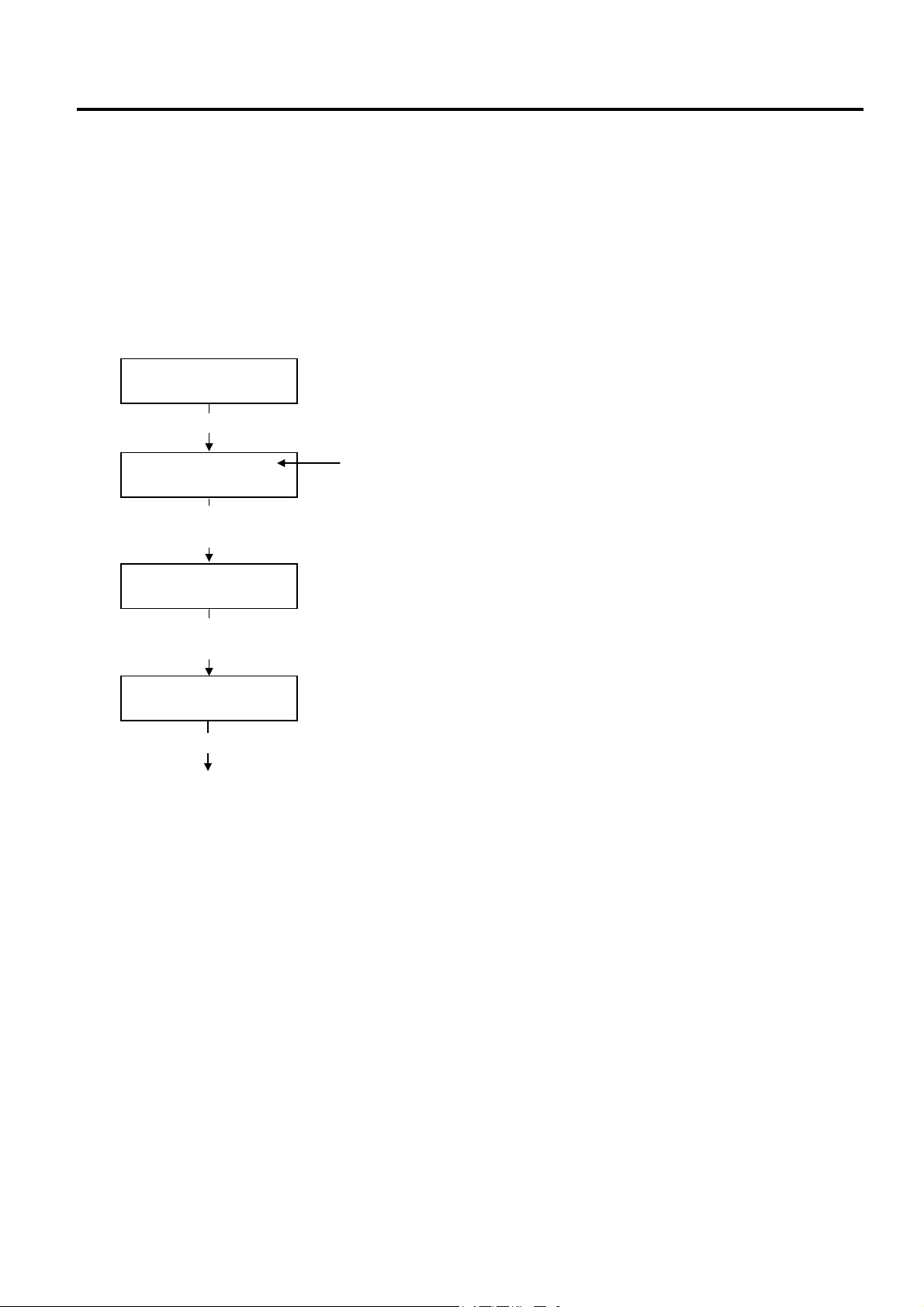
3. ON LINE MODE EO13-33002
f
3.4 BASIC Expansion Mode
3.4 BASIC Expansion Mode
It is possible to execute the BASIC expansion mode program in BASIC expansion mode under the following
conditions:
• The BASIC expansion mode program has already been loaded.
• The BASIC enable setting mode is selected.
The basic expansion mode ends when the basic expansion program is exited.
How to Perform BASIC Expansion
ON LINE
B-SX8T Vx.x
[PAUSE]
PAUSE 52
B-SX8T Vx.x
Press and hold the [RESTART]
key for 3 seconds or longer.
<1>RESET
Press the [FEED] key until
<5>EXPAND MODE is displayed.
<5>EXPAND MODE
[PAUSE]
BASIC program is executed.
Press the [PAUSE] key to stop printing.
The number of remaining print count
NOTE: When the [PAUSE] key is pressed during printing, the number o
remaining print count is displayed.
3- 8
 Loading...