

Page 1

TOSHIBA Barcode Printer
B-SX600 SERIES
Document No. EO10-33021
Original Sep., 2008
(Revised )
Product Description
Page 2

EO10-33021
(Revision Date: Nov. 21, 2008)
TABLE OF CONTENTS
Page
1. OUTLINE -------------------------------------------------------------------------------------------------1- 1
1.1 PRINTER SPECIFICATIONS ---------------------------------------------------------------------------1- 1
1.2 DESCRIPTION OF MODEL NUMBER --------------------------------------------------------------- 1- 2
1.3 PART NAMES NAD FUNCTIONS -------------------------------------------------------------------- 1- 3
1.4 OPERATION PANEL-------------------------------------------------------------------------------------- 1- 5
1.5 DIMENSIONS (APPROXIMATE) ---------------------------------------------------------------------- 1- 6
1.6 OPERATING ENVIRONMENT -------------------------------------------------------------------------1- 6
1.7 BASIC SPECIFICATIONS ------------------------------------------------------------------------------- 1- 7
1.8 CUTTER UNIT SPECIFICATIONS (B-SX600-HC11/HC12-QM-R model) ------------------1- 8
1.9 STRIP UNIT SPECIFICATIONS (B-SX600-HH11/HH12-QM-R MODEL)------------------- 1- 8
1.10 MECHANICAL BLOCK ----------------------------------------------------------------------------------- 1- 9
1.10.1 Mechanism ----------------------------------------------------------- 1- 9
1.10.2 Outline of the Mechanical Block ------------------------------------------------------------- 1-12
1.10.3 Print Head Block --------------------------------------------------------------------------------- 1-13
1.10.4 Media Roll Holder -------------------------------------------------------------------------------- 1-14
1.10.5 Lower Unit ----------------------------------------------------------------------------------------- 1-15
1.10.6 Strip Unit ------------------------------------------------------------------------------------------- 1-16
1.10.7 Cutter Unit ----------------------------------------------------------------------------------------- 1-17
1.10.8 Position of various sensors ------------------------------------------------------------------- 1-18
2. ELECTRONIC SPECIFICATIONS -----------------------------------------------------------------2- 1
2.1 ELECTRONIC BLOCK------------------------------------------------------------------------------------ 2- 1
2.2 BLOCK DIAGRAM -----------------------------------------------------------------------------------------2- 2
2.3 DESCRIPTION OF THE MAIN PC BOARD---------------------------------------------------------2- 3
2.3.1 Parts Side Layout--------------------------------------------------------------------------------- 2- 3
2.3.2 Solder Side Layout -------------------------------------------------------------------------------2- 4
2.3.3 Outline of the ICs and Connectors ----------------------------------------------------------- 2- 5
2.4 DESCRIPTION OF THE DRIVER PC BOARD---------------------------------------------------- 2-10
2.4.1 PC Board Layout -------------------------------------------------------------------------------- 2-10
2.4.2 Outline of the ICs and Connectors ---------------------------------------------------------- 2-11
3. MEDIA AND RIBBON SPECIFICATIONS -------------------------------------------------------3- 1
3.1 SUPPLY SPECIFICATIONS ---------------------------------------------------------------------------- 3- 1
3.2 DIE-CUT LABEL-------------------------------------------------------------------------------------------- 3- 2
3.3 NOTCHED MEDIA----------------------------------------------------------------------------------------- 3- 3
3.4 LABEL WITH BLACK MARKS-------------------------------------------------------------------------- 3- 4
3.5 GUARANTEED PRINT AREA --------------------------------------------------------------------------3- 5
3.6 STORAGE OF MEDIA AND RIBBONS -------------------------------------------------------------- 3- 6
3.7 UNACCEPTABLE MEDIA AND RIBBONS---------------------------------------------------------- 3- 6
Page 3

EO10-33021
(Revision Date: Nov. 21, 2008)
4. INTERFACE ---------------------------------------------------------------------------------------------4- 1
4.1 Expansion I/O Interface-----------------------------------------------------------------------------------4- 1
4.1.1 Scope------------------------------------------------------------------------------------------------ 4- 1
4.1.2 Basic System Configuration and Scope of Application ---------------------------------4- 1
4.1.3 General Description of the Expansion I/O Interface of this Printer------------------- 4- 1
4.1.4 Mode of the Expansion I/O Interface --------------------------------------------------------4- 2
4.1.5 External Signal Connector --------------------------------------------------------------------- 4- 2
4.1.6 Pin Layout ------------------------------------------------------------------------------------------ 4- 3
4.1.7 PIN Description -----------------------------------------------------------------------------------4- 3
CAUTION!
1. This manual may not be copied in whole or in part without prior written permission of TOSHIBA
TEC.
2. The contents of this manual may be changed without notification.
Copyright © 2008
by TOSHIBA TEC CORPORATION
A
ll Rights Reserved
570 Ohito, Izunokuni-shi, Shizuoka-ken, JAPAN
Page 4

1. OUTLINE EO10-33021
1.1 PRINTER SPECIFICATIONS
1-1
1. OUTLINE
1.1 PRINTER SPECIFICATIONS
1) High quality and resolution
• The resolution in the media feed direction is 1200 dpi, the highest resolution for label printers.
• This printer can precisely print on a 3-mm long label, also can peel off 10-mm long label.
• Prevents change of the ribbon tension which causes ribbon wrinkles.
• Prevents an imbalance contact of the print head with the media and blurred print at the media edges.
2) Interface
• Use of the printer driver eliminates the need of learning any printer specific commands. Also, it is
possible to develop a general-purpose system according to the standard specification.
• Bi-directional communication feature and status monitor API enable the host application to correctly
obtain a end of print job status even when using the printer driver.
• For network printing, the standard print protocol (LPR, Raw) has been adopted.
Bi-directional communication feature of Raw enables obtaining an end of print job status via network.
Like the USB interface model, it realizes complete management of print jobs. Network printing can
be performed without any special printing software.
3) User friendliness
• Very easy supply loading due to the pop-up mechanism of the print head block.
• Easy-to-understand operation menus enable user intuitive operations.
• Large LCD panel displays the printer status or operating procedures. (Language is selectable
between Japanese and English.)
• Print head and platen roller can be replaced without any tools.
• Simple driver installer enables easy and secure installation of the printer driver.
4) Safety and environment consciousness
Interlock switch:
While the cover is opened, printing operation is stopped and the power supply to the print head is shut
down.
User protection:
This printer is designed so that users cannot touch the moving parts such as the platen roller or the cutter
unit.
EMC (Electromagnetic compatibility):
Emission of electromagnetic noise, which influences other electronics devices, is reduced. Also, the
immunity to electromagnetic noise generated by surrounding devices is enhanced.
No use of hazardous chemical substances
Compliance with EU RoHS directive
5) Option
A variety of options are provided to meet your needs.
• Cutter module (Factory option)
• Strip module (Factory option)
• Network adapter (Factory option)
Network interface: 10BASE-T/100BASE-TX (Automatic sensing), Protocol: TCP-IP
Notes:
1. B-SX600 Series does not support TPCL (TEC Printer Command Language).
2. Printable bar code, two-dimensional code, and font type depend on PC’s operating environment and
application software.
3. In the Low Power Mode, the fan motor pauses as a proper operation.
4. When the power is on, the ribbon motor works for applying proper tension to the ribbon.
Page 5

1. OUTLINE EO10-33021
1.2 DESCRIPTION OF MODEL NUMBER
1-2
1.2 DESCRIPTION OF MODEL NUMBER
B – S X 6 0 0 – H
S 1 1 – Q M - R
RoHS compliance model
Destination Code
QM: Standard for World Wide
Issue Mode
S: Batch
H: Strip
C: Cut
Resolution
H: 600 dpi
Interface
1: USB
2: LAN
Machine Version
Page 6
1. OUTLINE EO10-33021
1.3 PART NAMES AND FUNCTIONS
1-3
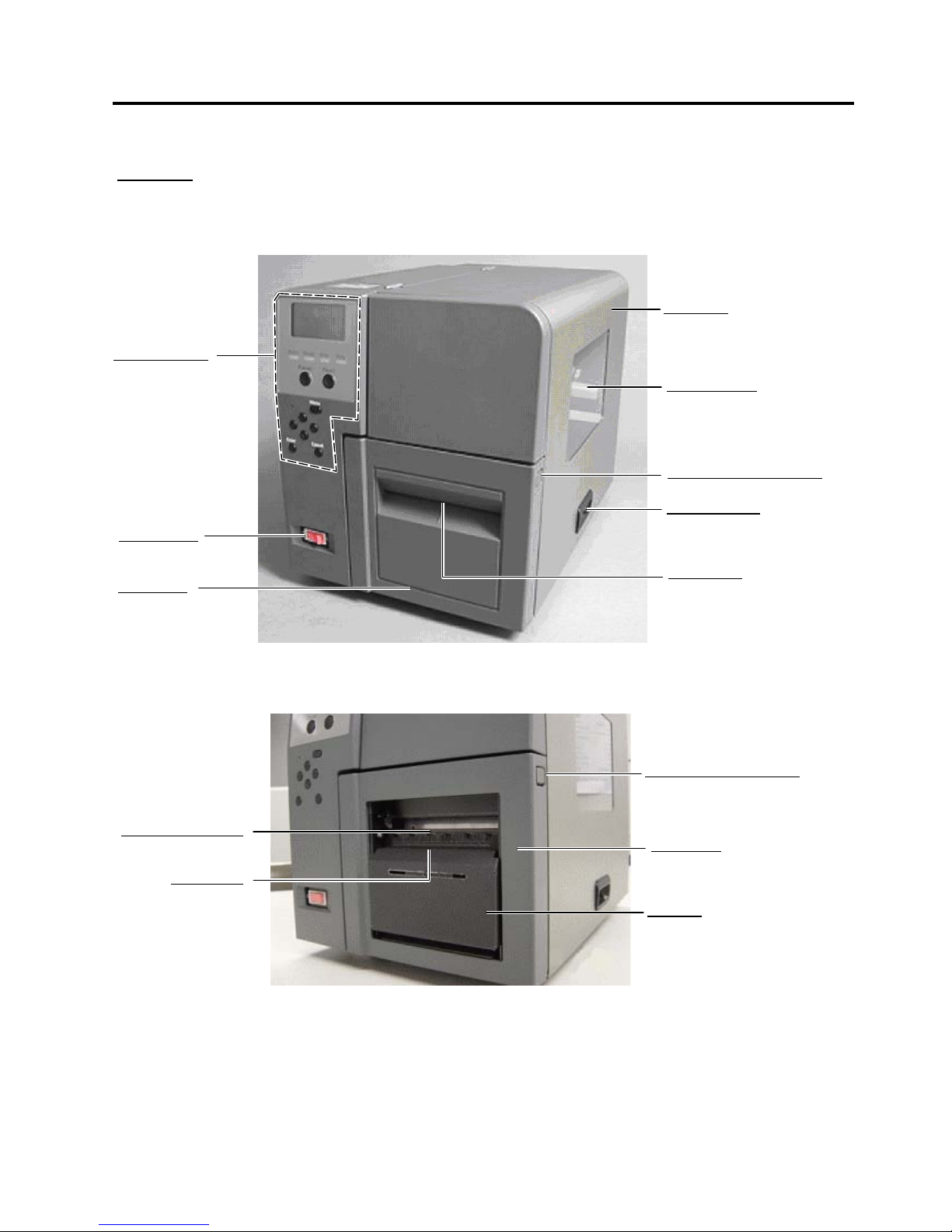
1.3 PART NAMES AND FUNCTIONS
Side Cover
Opened when the media o
r
ribbon is loaded or replaced.
Supply Window
A
remaining quantity of the
media or ribbon can be
checked through the Supply
Window.
Front Cover Unlock Button
Used to open the Front Cover.
Side Cover Grip
Used to open the Side Cover.
Media Outlet
Printed outputs are ejected
through the Media Outlet.
Front Cove
r
Opened when the
media is loaded o
r
replaced.
Power Switch
Used to turn the
p
rinter on/off.
Front View
Standard model or Cutter model
Strip model
Front Cover Unlock Button
Used to open the Front Cover.
Front Cover
Opened when the media is
loaded or replaced.
Strip Unit
Media Holding Roller
Strip Senso
r
Operation Panel
Used to following.
•Select a menu
•Printer Setting
•Display Message
etc.
(For details, refer to
section 1.4)
Page 7
1. OUTLINE EO10-33021
1.3 PART NAMES AND FUNCTIONS
1-4
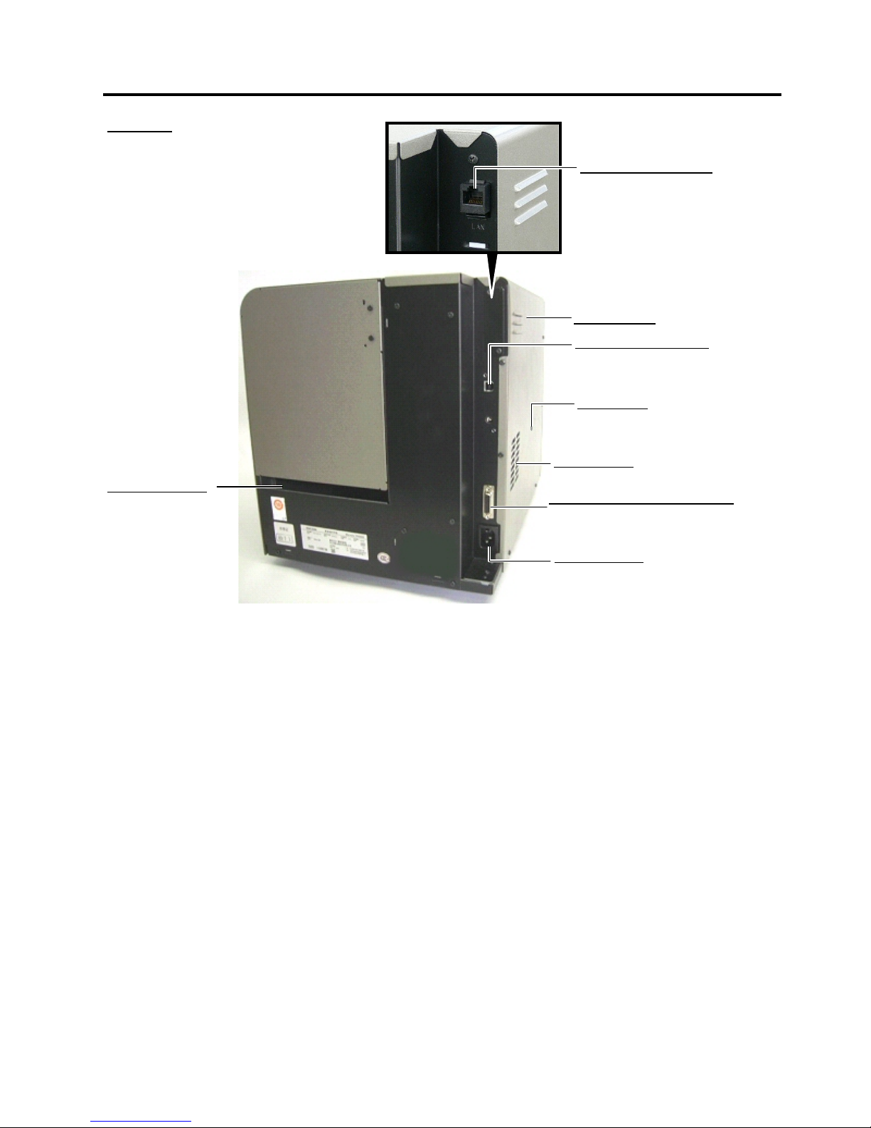
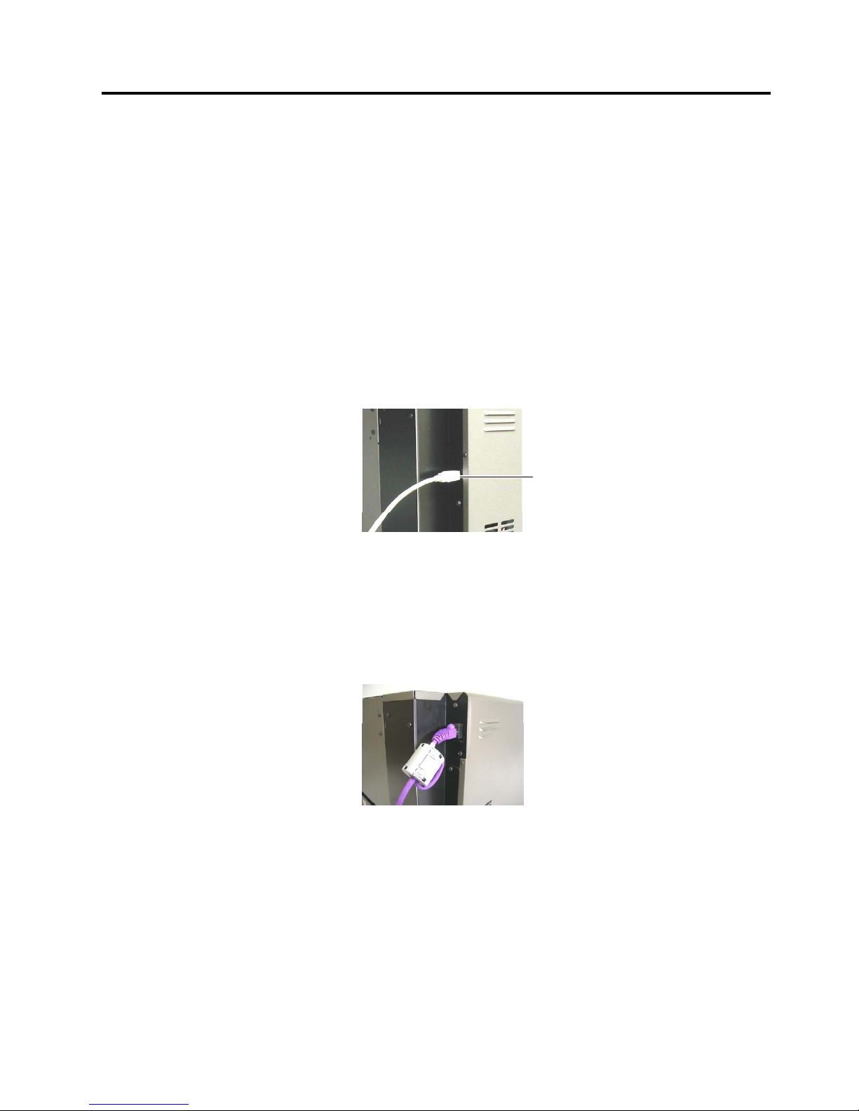
Rear View
USB Interface Connecto
r
Used to connect the printer to a PC
with a USB cable.
(USB Interface model only)
Ventilation Slot
Lets trapped heat pass out of the printer.
Expansion I/O Interface Connecto
r
Used to interface with an external
equipment (Refer to Section 4.)
A
C Power Inlet
Fanfold Paper Slot
A
llows fanfold paper to
feed into the printer from
the printer back.
LAN Interface Connecto
r
Used to connect the printer to a PC
with a LAN cable.
(LAN Interface model only)
Left Side Panel
Reset Switch
Used to reset the print server to the
factory default by the insertion of the
reset pin into the hole.
Page 8
1. OUTLINE EO10-33021
1.4 OPERATION PANEL
1-5
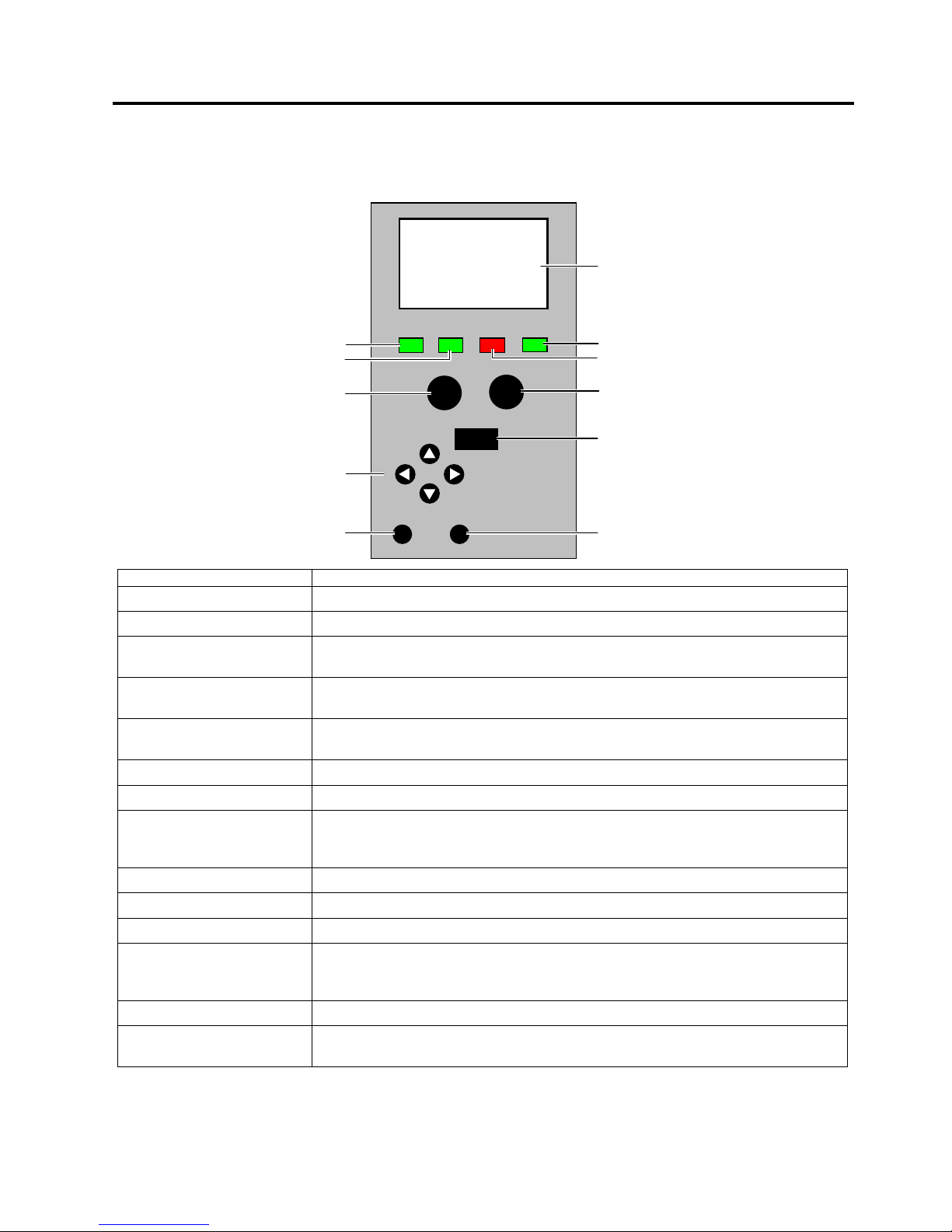
1.4 OPERATION PANEL
The Operation Panel is equipped with the LCD Message Display, which is used to indicate the state of the
printer, 4 LED’s, and 9 keys. Please see the table below for details.
Name Functions (Purposes)
LCD Message Display Shows the menu or error information.
Power LED Illuminates in green when the printer is turned on.
Ready LED Illuminates in green when the printer is ready, and goes out when the printer is in
a pause state or while the menu is being displayed.
Error LED Illuminates in red when an error occurs, and flashes in red in the event of a
warning.
Data LED Flashes in green when data is received, and illuminates in green when data is in
the receive buffer.
[Pause] key Used to place the printer in a pause or ready state.
[Feed] key Used to feed the media for a single page or label length.
[Menu] key Used to display the menu when the printer is in a ready or pause state. When
held down, the [Menu] key will be locked, and when held down again, it will be
unlocked.
◄key
Used to choose an item on the left while the menu is being displayed.
►key
Used to choose an item on the right while the menu is being displayed.
▲key
Used to choose an item above while the menu is being displayed.
▼key
Used to choose an item below while the menu is being displayed.
When the model with the Cutter Unit is used, holding down this key in a ready or
pause state causes the media to be cut.
[Enter] key Used to determine the settings while the menu is being displayed.
[Cancel] key Used to clear an error when it occurs.
When held down, print data is cleared.
LCD Message Display
Error LED
[
Feed]Key
[
Menu] Key
[
Cancel] Key
Ready
No. 00000
Power
Ready
Error Data
Ente
r
Menu
Pause
Feed
Cancel
Data LED
Power LED
Ready LED
[PAUSE] Key
Cursor Keys
(◄ ► ▲ ▼)
[Enter] Key
Page 9
1. OUTLINE EO10-33021
1.5 DIMENSIONS (APPROXIMATE)
1-6
A
cceptable operating
range
Print quality
guaranteed range
10 20 30 40
20
40
60
80
%RH
℃
5℃90%
29℃90%
5℃
55%
40℃39%
40℃10%
18℃
60%
28℃
60%
28℃
40%
18℃
40%
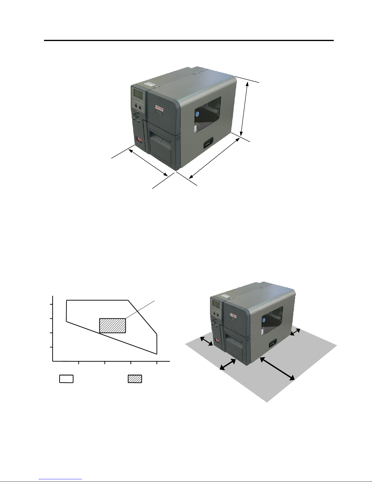
1.5 DIMENSIONS (APPROXIMATE)
1.6 OPERATING ENVIRONMENT
Install the printer in a place where ample space is reserved for the operation. Also, place the printer on a
well ventilated, smooth, level desk or rack specifically designed for the printer. Make sure that the 4 feet of
the printer make full contact with the surface of the desk or rack.
Be sure that there is sufficient space around the printer, as illustrated below.
Depth: 455mm
Width: 300mm
Height: 353.5mm
(including the rubber feet)
Min 15cm
Min 30cm
Min 5cm
Min 10cm
Page 10
1. OUTLINE EO10-33021
1.7 BASIC SPECIFICATIONS
1-7
1.7 BASIC SPECIFICATIONS
(1) Printing method: Thermal direct printing or thermal transfer printing
(2) Resolutions (dot density): 600 dpi (23.6 dots/mm)
(3) Print speed: Max. 150 mm/second (6ips)
There are limitations on a print speed depending on the media or ribbon
type and an image to print.
Note: Print speed is selectable from 1 ips to 6 ips by the printer driver.
(4) Media alignment: Center
(5) Max. effective print width: 104 mm (Approximate 4”)
(6) Max. print length: 1,000 mm
(7) Available media width: 15 to 120 mm
(8) Host interface: USB model: B-SX600-HS11/HH11/HC11-QM-R
• USB 2.0 High Speed
LAN model: B-SX600-HS12/HH12/HC12-QM-R
• 10BASE-T / 100BASE-TX (IEEE802.3)
• Print Protocol: LPR, PORT9100 (unidirectional), PORT9100
(bi-directional)
• LPR queue name: lp
• Control protocol: HTTP
(9) Operating system: Windows 2000, Windows XP, Windows Server 2003, Windows Vista
(10) Weight: 20.6 kg (USB model: B-SX600-HS11/HH11/HC11-QM-R)
21.0 kg (LAN model: B-SX600-HS12/HH12/HC12-QM-R)
(11) Rating: Input Voltage: 100 VAC to 240 VAC
Frequency: 50/60 Hz (48 to 62 Hz)
Power consumption: 250 W or less under normal operation
20W or less under low power mode operation
Type B
Page 11

1. OUTLINE EO10-33021
1.8 CUTTER UNIT SPECIFICATIONS (B-SX600-HC11/HC12-QM-R MODEL)
1-8
(12) Noise: 75 dB or less
(13) Operating temperature range: 5 to 40 °C (Print quality guaranteed at temperatures between 18 and 28
°C)
(14) Relative humidity: 10 to 90% (Print quality guaranteed at humidity between 40 and 60%)
(15) Storage temperature range: -20 to 70 °C
(16) Storage humidity range: 5 to 90%
(17) Safety and EMC Standard: CE, TÜV GS, C-Tick, UL, CUL, FCC, ICE, CCC
(18) Environmental standard: RoHS Directive compliant
1.8 CUTTER UNIT SPECIFICATIONS (B-SX600-HC11/HC12-QM-R MODEL)
(1) Acceptable media thickness: 0.08 mm to 0.26 mm
(2) Acceptable label pitch: 10 mm to 1,000 mm
(3) Cut mode: Continuous cut
Cut after printing
Batch cut
(4) Restrictions: Cutting self-adhesive labels is not allowed.
Cutting within 1 mm around perforation is not allowed.
Cutting fabrics or films is not allowed.
Note: The cutter unit is a factory option.
1.9 STRIP UNIT SPECIFICATIONS (B-SX600-HH11/HH12-QM-R MODEL)
(1) Effective print speed: 101.6 mm/second or less (same as a feed speed)
(2) Peeling method: Tensioning
(3) Peeling detection system: A reflective photo sensor is used to detect a label.
(4) Restrictions: Peel-off operation is not allowed when:
Perforated labels are used
Fanfold labels are used.
Fabrics or films are used
Outside wound labels are used
Labels other than rectangular die-cut labels are used.
Note: The strip unit is a factory option.
Page 12
1. OUTLINE EO10-33021
1.10 MECHANICAL BLOCK
1-9
1.10 MECHANICAL BLOCK
1.10.1 Mechanism
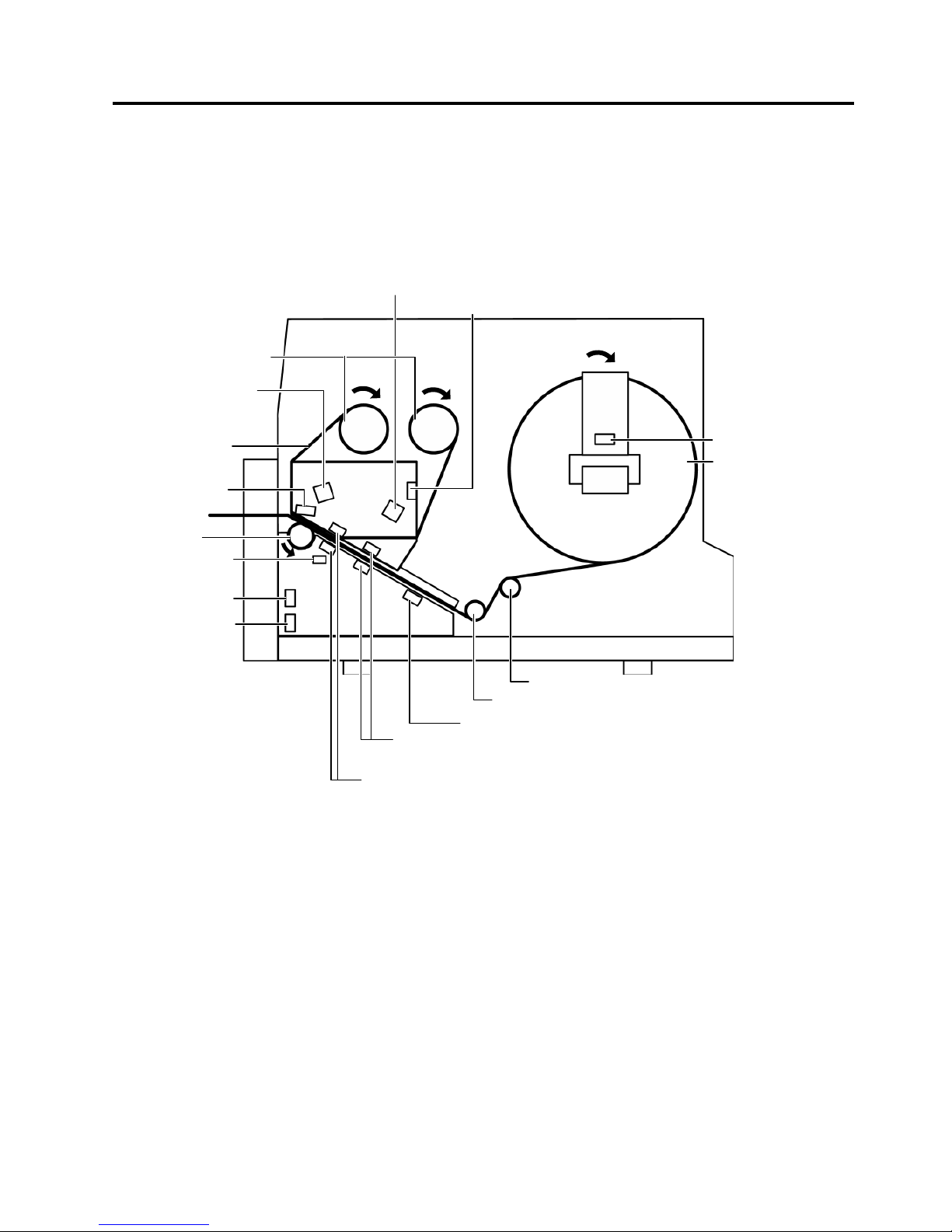
(1) Batch Mechanism (HS11/HS12 model)
This is the standard mechanism which lets the printer print continuously until the number of media specified
in the label issue command has been printed.
Media
Media Near End Sensor
Ribbon End Sensor
Ribbon Encoder Sensor
(Ribbon slit Sensor, Feed)
Ribbon
Ribbon Shaft
Front Cove
r
Open Senso
r
Side Cove
r
Open Senso
r
Media End Sensor
Movable Media Sensor (Feed Gap Sensor),
Reflective Media Sensor (Black Mark Sensor)
Print Head
Ribbon Encoder Senso
r
Ribbon slit Sensor, Take-up)
Print Head
O
p
en Senso
r
Fixed Media Sensor (Feed Gap Sensor)
Platen
Media Roll Damper
Media Roll Guide
Page 13

1. OUTLINE EO10-33021
1.10 MECHANICAL BLOCK
1-10
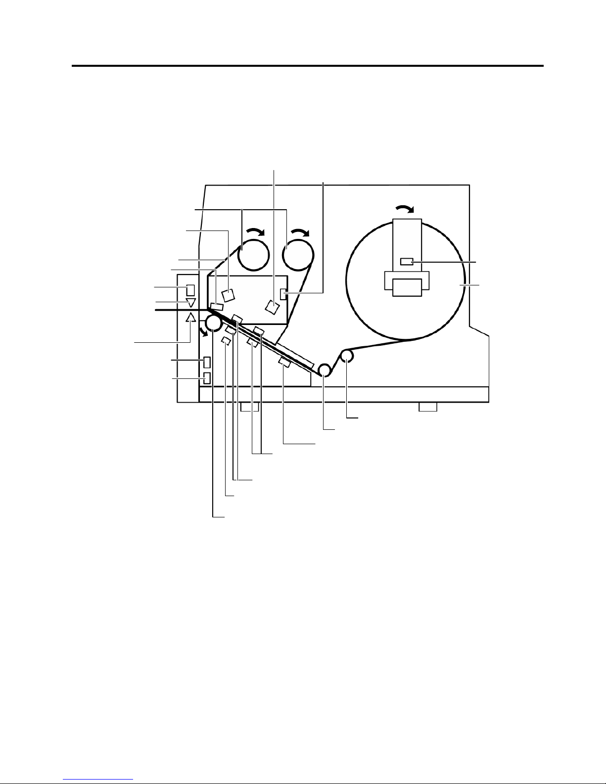
(2) Strip Mechanism (HH11/HH12 model)
When an factory optional strip module is attached, a label is stripped from the backing paper by the strip
shaft, and the backing paper is drawn into the strip module. The nextlabel will not be printed until the
preceding label is removed, as a presence of the label at the strip shaft is monitored by the strip sensor.
Media
Media Near End Sensor
Ribbon End Sensor
Ribbon
Ribbon Shaft
Front Cove
r
Open Senso
r
Feed Roller (Black)
Media End Sensor
Print Head
Print Head Open Sensor
Platen
Pinch Roller (White)
Strip senso
r
Backing Pape
r
Side Cove
r
Open Senso
r
Media Holding
Rolle
r
Media Roll Damper
Media Roll Guide
Strip Plate
Movable Media Sensor (Feed Gap Sensor),
Reflective Media Sensor
(
Black Mark Sensor
)
Fixed Media Sensor (Feed Gap Sensor)
Ribbon Encoder Sensor
(Ribbon slit Sensor, Feed)
Ribbon Encoder Senso
r
Ribbon slit Sensor, Take-up)
Page 14
1. OUTLINE EO10-33021
1.10 MECHANICAL BLOCK
1-11
3) Cutter Mechanism (HC11/HC12 model)
When an factory optional Cutter module is attached, printed media is fed to the cutter unit and cut off from
the media roll.
Media
Media Near End
Sensor
Ribbon End Sensor
Ribbon
Ribbon Shaft
Front Cove
r
Open Senso
r
Media End Sensor
Print Head
Print Head Open Sensor
Platen
Cutter Blade
Media Roll Damper
Media Roll Guide
Side Cove
r
Open Senso
r
Cutter Carriage
Position Senso
r
Cutter Carriage Unit
Transmissive Media Edge Sensor (Feed Gap Sensor, Movable)
Reflective Media Sensor (Black Mark Sensor)
Transmissive Media Center Sensor (Feed Gap Sensor, Fixed)
Ribbon Encoder Sensor
(Ribbon slit Sensor, Feed)
Ribbon Encoder Senso
r
(Ribbon slit Sensor, Take-up)
Page 15

1. OUTLINE EO10-33021
1.10 MECHANICAL BLOCK
1-12
1.10.2 Outline of the Mechanical Block
The main Mechanical Blocks are as follows.
Front Cover (HS11/HS12)
Cutter Unit (HC11/HC12)
Strip Unit (HH11/HH12)
Upper Uni
t
Media Roll Holder and
Damper Unit
Lower unit
Page 16

1. OUTLINE EO10-33021
1.10 MECHANICAL BLOCK
1-13
1.10.3 Print Head Block
The main parts of the Print Head Block are as follows.
Ribbon Tensioner
Print Head Block Handle
Ribbon Stopper
Ribbon Stoppe
r
Ribbon Shaft
(Supply Side)
Ribbon Shaft
(Take up side)
Print Head
Release Leve
r
Upper Unit
Unlock Lever
Print Head Ass’
y
Print Head Pressure
Selection Lever
Page 17

1. OUTLINE EO10-33021
1.10 MECHANICAL BLOCK
1-14
1.10.4 Media Roll Holder
The main parts of the Media Holder Block are as follows.
Note: The on or off status of the media near end sensor can be switched with the Lever. Move the lever
into OFF position for using the fanfold paper. If it remains in ON position, a media near end error is
detected, causing that no print operation is performed.
Unlock Lever
Media Roll Holder Unit
Media Near End Sensor
By adopting a reflective
sensor, this sensor detects
a media near end state
when the media is reduced
under the sensor window.
OFF position
ON position
Lever
Sensor Window
Page 18

1. OUTLINE EO10-33021
1.10 MECHANICAL BLOCK
1-15
1.10.5 Lower Unit
The main parts of the Lower Unit are as follows.
Media Roll Damper
Media Roll Guide
Media Guide
Media Holder
Media End Sensor
Fixed Media Sensor (Fixed Feed Gap Sensor)
Movable Media Sensor
(Movable Feed Gap Sensor)
Reflective Media Sensor
(Black Mark Sensor)
Platen
Page 19

1. OUTLINE EO10-33021
1.10 MECHANICAL BLOCK
1-16
1.10.6 Strip Unit
The main parts of the Strip Module are as follows.
Strip Module
Pinch Roller
(White)
Feed Roller
(Black)
Media Holding
Roller
Strip Sensor
Page 20

1. OUTLINE EO10-33021
1.10 MECHANICAL BLOCK
1-17
1.10.7 Cutter Unit
The main parts of the Cutter Unit are as follows.
Cutter Motor
Cutter Carriage
Position Senso
r
Cutter Carriage
Unit
Cutter Blade
Page 21

1. OUTLINE EO10-33021
1.10 MECHANICAL BLOCK
1-18
1.10.8 Position of various sensors
Cutter Carriage Position Sensor
• It detects the position of the
cutter.
Front Cover Open Sensor
(1) Cover open
It detects the open or close
status of the front cover.
(2) Interlock function
It performs as a safety
interlock switch.
Print Head Open Sensor
• It detects the open or
close status of the print
head by working with the
home position sensor.
Print Head Thermistor
• It measures the
temperature of the print
head.
Side Cover Open Sensor
(1) Cover open
It detects the open or
close status of the
side cover.
(2) Interlock function
It performs as a safety
interlock switch.
Ribbon Encoder Sensor
• It monitors the rotation of the ribbon shaft.
• It detects the tear of the ribbon.
Ribbon End Sensor
• It detects a ribbon end.
Media Near End Sensor
• It detects the remaining
number of media.
(1) Transmissive Media Edge
Sensor Sensor
(2) Reflective Media Sensor
(3) Transmissive Media Center
Sensor
• The above sensors optically
measure potential difference
of the media to measure the
media length.
Home Position Sensor (Print Head Open Sensor)
• It detects the open or close status of the print
head by working with the print head open sensor.
Media End Sensor
• It detects a media end.
Environmental Temperature
Thermistor
• It measures the operating
temperature of the printer
to adjust print energy.
Page 22

1. OUTLINE EO10-33021
1.10 MECHANICAL BLOCK
1-19
Note:
The sensor is selectable from Movable Media Sensor, Reflective Media Sensor, and Fixed Media Sensor by the
printer driver.
Refer to Owner’s Manual or Printer Driver Users Manual.
Fixed Media Sensor (Fixed Feed Gap Sensor)
This sensor detects the tag paper in which
center a round hole (3 mm in diameter) is
provided.
Page 23

2. ELECTRONIC SPECIFICATIONS EO10-33021
(Revision Date: Nov. 21, 2008)
2.1 ELECTRONIC BLOCK
2-1
2. ELECTRONIC SPECIFICATION
2.1 ELECTRONIC BLOCK
The main parts of the Electronic Block are as follows.
Ribbon Motor
(Take up)
Driver PC
Board
Stepping motor
Main PC
Board
Fan Moto
r
Ribbon Motor
(Supply)
LAN Unit
(LAN model only)
Cutter Control PC Board
(HC11/HC12 model)
5V Power
Supply Unit
24V Power
Supply Unit
Noise Filter
PC Board
Operation Panel
PC Board
LCD Panel
Page 24

2. ELECTRONIC SPECIFICATIONS EO10-33021
(Revision Date: Nov. 21, 2008)
2.2 BLOCK DIAGRAM
2-2
2.2 BLOCK DIAGRAM
Page 25

2. ELECTRONIC SPECIFICATIONS EO10-33021
(Revision Date: Nov. 21, 2008)
2.3 DESCRIPTION OF THE MAIN PC BOARD
2-3
2.3 DESCRIPTION OF THE MAIN PC BOARD
2.3.1 Parts Side Layout
CN2
Print Head
(Print Data, Control
Si
g
nal
)
CN7 (Not used)
CN4 (Panel PC Board)
CN11 CPLD JTAG (Joint Test Action Group)
Not used, for Developer
CN8 H-UDI Interface
Not used, for Develope
r
FU2 Fuse
FU1 Fuse
IC22 PROM (Not installed)
CN10 FPGA JTAG (Not installed)
IC19 FPGA
IC3
Buffer
IC5
Buffer
SW1 (CPLD)
Not installed
IC4 CPLD
(Complex
Programmable
Logic Device)
IC16 IC17 IC18
128M bit SDRAM
IC8 32 bit
RISC CPU
SH7206
SW2 (for FPGA)
Not used
IC21
Buffer
IC20
Buffer
OSC3 Oscillator
33.33MHz
IC15
16M bit Flash ROM
IC14
Buffer
IC9
Buffer
IC7 Reset IC
CN1 USB
CN5 5VDC
(Not used)
FU3 Fuse
CN9 AUD (Advanced User Debugger)
Not used
IC1 DC/DC Converter (3.3V)
FU4 Fuse
FU5 Fuse
IC2 DC/DC Converter (1.2V, 1.25V)
OSC1 Oscillato
r
24MHz
IC6 USB Controlle
r
OSC2 Oscillator
12.5MHz
IC11
IC10
IC13
IC12
Multiplexe
r
CN6 VFR Interface
(Not installed)
Page 26

2. ELECTRONIC SPECIFICATIONS EO10-33021
(Revision Date: Nov. 21, 2008)
2.3 DESCRIPTION OF THE MAIN PC BOARD
2-4
2.3.2 Solder Side Layout
IC27 Reset IC
PST9246N
REG2 Regulator
(1.5V)
IC26 16M bit Flash ROM
IC25
Buffer
IC23
Buffer
IC24
Buffer
REG3 Regulato
r
(2.5V)
CN3 Driver
PC Board
REG1 Regulato
r
(1.8V)
Not installed
Page 27

2. ELECTRONIC SPECIFICATIONS EO10-33021
(Revision Date: Nov. 21, 2008)
2.3 DESCRIPTION OF THE MAIN PC BOARD
2-5
2.3.3 Outline of the ICs and Connectors
The Main PC board functions as a central part of the printer and controls the operation of print head.
This PC board is comprised of the following major components:
Main Electronic parts
CPU (IC8): 32bit RISC CPU
Type: SH7206
Clock: Max. 200MHz
This IC is a central part of the electric system, which performs the following
processing.
Controlling the data bus and address bus
Controlling the serial interface
Controlling the interruption
Performing as the A/D converter
Performing as the D/A converter
Flash ROM (IC15, 26): 32Mbit Flash ROM
Type: S29AL016D70
Various setting values of firmware program, sensor setting, etc. are written
into this memory.
SDRAM (IC16, 17, 18): 128Mbit SDRAM
Type: EDS1216AATA-75-E
This memory is used for drawing the print data.
It is not possible to store writable characters, etc. into the printer which
does not support TEC Printer Command Language.
FPGA (IC19): Type: XC3S1500
This IC is a Field Programmable Gate Array (FPGA), which performs
controlling the devices such as cutter, print head, ribbon motor, and
sensors.
Page 28

2. ELECTRONIC SPECIFICATIONS EO10-33021
(Revision Date: Nov. 21, 2008)
2.3 DESCRIPTION OF THE MAIN PC BOARD
2-6
CPLD (IC4): Type: EPM3128ATC100
This IC is a Complex Programmable Logic Device (CPLD).
USB Controller (IC6) Type: M66592WG
This IC is used for controlling the USB interface.
DC/DC Converter (IC1, 2): Type: TPS54380PWPG4
These ICs are DC/DC converters. From +5V, IC1 generates +3.3V and
IC2 generates +1.25V and +1.2V, respectively.
+3.3V is used as the operating voltage for logic devices such as CPU.
+1.25V is used as the supply voltage for the CPU.
+1.2V is used as the operating voltage for the FPGA (IC19).
Regulator (REG2, 3): Type: PQ070XH02ZPH
They are regulator ICs.
From +3.3V, REG2 generates +1.5V and REG3 generates +2.5V,
respectively.
+1.5V is used for the USB controller (IC6).
+2.5V is used as the operating voltage for the FPGA (IC19).
Page 29

2. ELECTRONIC SPECIFICATIONS EO13-33001
(Revision Date: Nov. 21, 2008)
2.3 DESCRIPTION OF THE MAIN PC BOARD
2-7
Connectors
CN1
CN4
Signal I/O Pin No.
USB_GND --- 1
D+ I/O 2
D- I/O 3
VBUS --- 4
Signal I/O Pin No.
PANEL_VDD_O O 1
PANEL_RESERVE2 I 2
PANEL_BUZZER O 3
PANEL_RESERVE1 O 4
PANEL_SDI I 5
PANEL_SDO O 6
PANEL_LCD_CS_N O 7
PANEL_LCD_A0 O 8
PANEL_SCLK O 9
GND --- 10
This is a USB interface connector.
The model with a USB interface is connected to a PC via the
connector.
The model with a LAN interface, not provided with the
connector, is connected to the printer server via the cable
directly installed into the PC board.
This connector is connected to the panel PC board.
The signals output from the connector are used fo
r
controlling the LCD display, buzzer, and so on.
Page 30

2. ELECTRONIC SPECIFICATIONS EO13-33001
(Revision Date: Nov. 21, 2008)
2.3 DESCRIPTION OF THE MAIN PC BOARD
2-8
CN2
Signal I/O Pin No.
HEAD_TEMP I 1
GND --- 2
HEAD_TRS5 I 3
HEAD_TRS6 I 4
HEAD_TRS3 I 5
HEAD_TRS4 I 6
HEAD_TRS1 I 7
HEAD_TRS2 I 8
HEAD_DATA13 O 9
GND --- 10
HEAD_DATA12 O 11
GND --- 12
HEAD_DATA11 O 13
GND --- 14
HEAD_DATA10 O 15
GND --- 16
HEAD_DATA9 O 17
GND --- 18
HEAD_DATA8 O 19
GND --- 20
HEAD_DATA7 O 21
GND --- 22
HEAD_DATA6 O 23
GND --- 24
HEAD_DATA5 O 25
GND --- 26
HEAD_DATA4 O 27
GND --- 28
HEAD_DATA3 O 29
GND --- 30
HEAD_DATA2 O 31
GND --- 32
HEAD_DATA1 O 33
GND --- 34
HEAD_STROBE2_N O 35
GND --- 36
HEAD_STROBE1_N O 37
GND --- 38
HEAD_CLOCK O 39
GND --- 40
HEAD_LATCH_N O 41
GND --- 42
HEAD_B_E_O O 43
GND --- 44
+5V O 45
GND --- 46
+5V O 47
GND --- 48
+5V O 49
GND --- 50
This connector is connected to the print head.
+5V, print data (HEAD DATA1 to HEAD DATA13), and
the strobe, clock, and latch signals which control the print
head are output from the connector.
A
lso, the thermistor signal (HEAD TEMP) which is used
for detecting the internal temperature of the print head
and the print head element resistance rank detect signal
(HEAD TRS1 to HEAD TRS6) are input into the
connector.
Page 31

2. ELECTRONIC SPECIFICATIONS EO13-33001
(Revision Date: Nov. 21, 2008)
2.3 DESCRIPTION OF THE MAIN PC BOARD
2-9
CN3
Signal I/O
Pin
No.
Signal I/O
Pin
No.
GND --- 1 GND --- 51
GND --- 2 GND --- 52
GND --- 3 GND --- 53
GND --- 4 GND --- 54
+5V I 5 +5V I 55
+5V I 6 +5V I 56
+5V I 7 +5V I 57
+5V I 8 +5V I 58
+5V I 9 +5V I 59
+5V I 10 +5V I 60
CO_VM_MONITOR I 11 CO_FAN_REVOLUTION I 61
CO_VTH_MONITOR I 12 CO_N_DISCHARGE O 62
CO_N_PSU_REMOTE O 13 EX_IF_LABEL_END O 63
EX_IF_ERROR O 14 EX_IF_CMP_NRMLTY O 64
EX_IF_CMP_ABNRMLTY O 15 EX_IF_READY_N_PAUSE O 65
EX_IF_PRINT_DATA O 16 EX_IF_RIBBON_END O 66
EX_IF_RESERVE_OUT O 17 EX_IF_PAUSE I 67
EX_IF_BACK_FEED I 18 EX_IF_RESERVE_IN I 68
EX_IF_PRINT_START I 19 CO_N_HEAD_ENABLE O 69
CO_N_HEAD_CHECK O 20 CUTE_M_CW_CCW O 70
CUTE_M_CLOCK O 21 CUTE_M_MODE_1 O 71
CUTE_M_POWER O 22 CUTE_M_MODE_3 O 72
CUTE_M_MODE_2 O 23 CO_OPT_SIG1 I 73
CUTE_M_RESET O 24 CO_OPT_SIG2 I 74
LF_MO_CLOCK O 25 LF_MO_CW_CCW O 75
LF_MO_POWER_1 O 26 LF_MO_POWER_2 O 76
LF_MO_MODE_1 O 27 LF_MO_MODE_2 O 77
LF_MO_MODE_3 O 28 LF_MO_RESET O 78
RB_M_WAND_UP_ENABLE O 29 RB_M_DELIVER_ENABLE O 79
RB_M_WAND_UP_MODE O 30 RB_M_DELIVER MODE O 80
RB_M_WAND_UP_PAHSE O 31 RB_M_DELIVER_PAHSE O 81
RB_M_WAND_UP_PFD_1 O 32 RB_M_DELIVER_PFD_1 O 82
RB_M_WAND_UP_PFD_2 O 33 RB_M_DELIVER_PFD_2 O 83
GND --- 34 GND --- 84
GND --- 35 GND --- 85
RB_M_WND_UP_REF O 36 RB_M_DELIVER_REF O 86
SEN_CENTER_HOLE I 37 SEN_HEAD_RESISTOR I 87
SEN_INTERRUPTER I 38 SEN_REFLECTIVE I 88
SEN_THERMISTOR I 39 SEN_RBN_END I 89
GND --- 40 GND --- 90
GND --- 41 GND --- 91
SEN_CUT_HP_LEFT_PEL I 42 SEN_CUT_HP_RIGHT I 92
SEN_PAPER_NEAR_END I 43 SEN_SIDE_COVER_OPEN I 93
SEN_HEAD_LATCH_OPEN I 44 SEN_HEAD_OPEN I 94
SEN_PAPER_END I 45 SEN_FRONT_COVER_OPN I 95
SEN_RBN_WAND_UP_ENC I 46 SEN_RBN_DELIVER_ENC I 96
SEN_RBN_PINCH I 47 LEDS_PULSE_INT O 97
LEDS_PULSE_CENTER O 48 LEDS_PULSE_REF O 98
RESERVE_IN_1 I 49 POWER_ON_IN I 99
RESERVE_OUT_1 O 50 POWER_ON_OUT O 100
This connector, which is
connected to the driver PC
board, performs the
input/output of the control
signals for the motor,
sensors, and so on.
A
lso, +5V, the operating
voltage for each logic
device, is supplied from
the connector.
Page 32

2. ELECTRONIC SPECIFICATIONS EO1033021
(Revision Date: Nov. 21, 2008)
2.4 DESCRIPTION OF THE DRIVER PC BOARD
2-10
2.4 DESCRIPTION OF THE DRIVER PC BOARD
2.4.1 PC Board Layout
In addition, the following PC boards are used in the printer.
24V Power Supply PC Board: Generate +24VDC
5V Power Supply PC Board: Generate +5VDC
Cutter Control PC Board: Control of the cutter
Operation Panel PC Board: Control of the operation panel.
Noise Filter PC Board: Reduce a noise of the power supply.
CN3 Ribbon Motor (Rewind)
CN8 Print Head
(Power)
CN5 Stepping
Motor
CN6
Cutter Drive
PC Board
FU4 Fuse
IC5 Stepping Motor
Driver
Heat Sink
FU6 Fuse
CN4 Ribbon Motor (Feed)
FU7 Fuse
CN2 Sensors
Ribbon End Sensor
Media Sensor (Movable Media sensor, Reflective Media
sensor, Fixed Media sensor)
Environmental Temperature Thermistor
CN1 Sensors
Media End Sensor
Media Near End Sensor
Print Head Open Sensor
Home Position Sensor (Print Head Open Sensor)
Front Cover Open Sensor
Side Cover Open Sensor
Ribbon Encoder Sensor (Ribbon Feed, Ribbon Rewind)
FU8 Fuse
CN7
MAIN PC Board
CN9 5VPS Unit
CN10 LAN Module
(LAN model only)
Q1 FET
(Power Switching)
CN14 24VPS Unit
IC8 IC9 IC10
Inverte
r
IC6 Motor Driver IC
(Rewind)
IC2
Op. AMP
IC7 Motor Driver IC
(Feed)
PC1PC2PC3
Photo Couple
r
IC3 Reset IC
IC4
DC/DC Converte
r
Q9
(Power Switch)
FU5 Fuse
FU1 Fuse
CN13 Fan Motor
IC1 Reset IC
CN11
Expansion I/O
Interface
CN12 5VPS Unit and 24VPS Unit
FU2 Fuse
FU3 Fuse
Page 33

2. ELECTRONIC SPECIFICATIONS EO1033021
(Revision Date: Nov. 21, 2008)
2.4 DESCRIPTION OF THE DRIVER PC BOARD
2-11
2.4.2 Outline of the ICs and Connectors
The Driver PC board controls devices such as stepping motor and DC motor, detects the sensor status, and
generates a voltage to work devices such as print head and motors.
Motor Driver IC (IC6, 7): Type: A3959SLP
These ICs generate the operating voltage for the ribbon motor.
IC6 generates the RIBBON_WAND_OUT_A and RIBBON_WAND_OUT_B
signals from +36V and the RBN_M_WAND_UP_PFD_1 and
RBN_M_WAND_UP_PFD_2 signals output from the CPU PC board, and
then it outputs these signals to the ribbon motor (rewind).
IC7 generates the RIBBON_DELIVER_OUT_A and
RIBBON_DELIVER_OUT_B signals from +36V and the
RBN_M_DELIVER_UP_PFD_1 and RBN_M_DELIVER_UP_PFD_2
signals output from the CPU PC board, and then it outputs these signals to
the ribbon motor (feed).
Stepping Motor Driver (IC5): Type: SLA7078MR
This is a driver IC which controls the stepping motor.
It generates the A, B, N_A, and N_B signals from +36V and the
LF_M_MODE and LF_M_CLOCK signals output from the CPU PC board,
and then it outputs these signals to the stepping motor.
NOTE:
The IC is provided with the heat sink. Never touch the IC which may
become hot immediately after the operation. Doing so may burn your
fingers or hands.
Photo Coupler (PC1 to PC3): Type: TLP281-4
These ICs are used as the input/output circuits of each signal for the
external I/O interface.
DC/DC Converter (IC4): Type: R1223N332G
This IC is a DC/DC converter which generates 3.3V from +5V.
3.3V is used as the operating voltage for each circuit, and so on.
IC5
Heat Sink
Page 34

2. ELECTRONIC SPECIFICATIONS EO1033021
(Revision Date: Nov. 21, 2008)
2.4 DESCRIPTION OF THE DRIVER PC BOARD
2-12
CN1
CN2
Signal I/O
Pin
No.
GND --- 1
R_PINCH_VDD O 2
SENS_RBN_OPN I 3
GND --- 4
D_RENC_VDD O 5
SENS_D_ENC I 6
GND --- 7
W_RENC_VDD O 8
SENS_W_ENC I 9
GND --- 10
SCVR_OPN_VDD O 11
SENS_NEAR_E I 12
GND --- 13
HEAD_UP_VDD O 14
SENS_HEAD_UP I 15
GND --- 16
P_NEND_VDD O 17
SENS_SCVR_OPN I 18
GND --- 19
P_END_VDD O 20
SENS_P_END I 21
GND --- 22
TH_OPEN_VDD O 23
SENS_TH_OPN I 24
GND --- 25
FCVR_OPN_VDD O 26
SENS_FCVR_OPN I 27
GND --- 28
RSRV_VDD O 29
SENS_RSRV I 30
This connector is connected to the sensors as follows. The
sensor control and sensor status signals are input into the
connector.
• Media End Sensor
• Media Near End Sensor
• Print Head Open Sensor
• Home Position Sensor (Print Head Open Sensor)
• Front Cover Open Sensor
• Side Cover Open Sensor
• Ribbon Encoder Sensor (Ribbon Feed, Ribbon Rewind)
Signal I/O
Pin
No.
A-GND --- 1
LED_CENT O 2
A-GND --- 3
CENT_SIG_VDD O 4
SENS_CENT_SIG I 5
A-GND --- 6
LED_REF O 7
SENS_REF_SIG I 8
A-GND --- 9
A-VDD1 O 10
SENS_THERMISTOR_SIG I 11
A-GND --- 12
A-GND --- 13
A-VDD2 O 14
SENS_A_RSRV I 15
A-GND --- 16
LED_INT O 17
A-GND --- 18
A-GND --- 19
INT_GIG_VDD O 20
SENS_INT_SIG I 21
A-GND --- 22
A-VDD3 O 23
SENS_RIBN_END_SIG I 24
This connector is connected to the sensors as follows. The
sensor control and sensor status signals are input into the
connector.
• Ribbon End Sensor
• Media Sensor (Transmissive Sensor, Reflective Sensor)
• Transmissive Media Center Sensor
• Environmental Temperature Thermistor
Page 35

2. ELECTRONIC SPECIFICATIONS EO1033021
(Revision Date: Nov. 21, 2008)
2.4 DESCRIPTION OF THE DRIVER PC BOARD
2-13
CN3
CN4
CN5
CN6
Signal I/O
Pin
No.
RIBBON_WAND_OUT_A O 1
RIBBON_WAND_OUT_B O 2
Signal I/O
Pin
No.
RIBBON_DELIVER_OUT_A O 1
RIBBON_DELIVER_OUT_B O 2
Signal I/O
Pin
No.
COM_A O 1
COM_B O 2
A O 3
N_A O 4
B O 5
N_B O 6
Signal I/O
Pin
No.
36V O A1
3.3V O A2
OPT_CUT_M_CLOCK O A3
OPT_CUT_M_RESET O A4
5V_P_3 O A5
OPT_CON_SIG_1 I A6
OPT_CON_SIG_2 I A7
OPT_CUT_M_MODE_1 O A8
OPT_CUT_M_MODE_2 O A9
OPT_CUT_M_MODE_3 O A10
CUT_M_HP_RIGHT I B1
CUT_M_HP_LEFT I B2
OPT_PEEL I B3
GND --- B4
GND --- B5
GND --- B6
OPT_CUT_M_POWER O B7
OPT_CUT_M_CW_CCW O B8
GND --- B9
GND --- B10
This connector is connected to the cutter drive PC board.
(It is used only for the model with the cutter, but unused for the
standard model and the model with the strip module.)
This connector is connected to the ribbon motor (rewind).
The RIBBON_WAND_OUT_A and RIBBON_WAND_OUT_B
signals generated from the motor driver IC (IC6) are output
from the connector.
This connector is connected to the ribbon motor (feed).
The RIBBON_DELIVER_OUT_A and
RIBBON_DELIVER_OUT_B signals generated from the moto
r
driver IC (IC7) are output from the connector.
This connector is connected to the stepping motor.
The COM_A and COM_B, operating voltage for the stepping
motor, are output from the pins 1 and 2, respectively.
The control signals A, N_A, B, and N_B are output from the
pins 3, 4, 5, and 6, respectively.
Page 36

2. ELECTRONIC SPECIFICATIONS EO1033021
(Revision Date: Nov. 21, 2008)
2.4 DESCRIPTION OF THE DRIVER PC BOARD
2-14
CN8
CN9
CN10
CN11
Signal I/O
Pin
No.
24V_TH O 1
24V_TH O 2
24V_TH O 3
24V_TH O 4
P_GND --- 5
P_GND --- 6
P_GND --- 7
P_GND --- 8
This connector is connected to the print head.
The 24V, operating voltage for the print head, is supplied
from the connector.
Signal I/O
Pin
No.
P_GND --- 1
GND --- 2
36V O 3
5V_P_1 O 4
This connector is connected to the print server.
The +5V and 36V, operating voltage for the print server is
supplied from the connector.
Signal I/O
Pin
No.
24V_EXIT_IN I 1
GND_EXT --- 2
EXT_BACK_FEED I 3
EXT_PRINT_START I 4
EXT_PAUSE I 5
EXT_RESERVE_IN I 6
EXT_ERROR O 7
EXT_PRINT_DATA O 8
GND_EXT --- 9
EXT_COMP_NORMALITY O 10
EXT_COMP_ABNORMALITY O 11
EXT_READY_PAUSE O 12
EXT_RIBBON_END O 13
EXT_LABEL_END O 14
EXT_RESERVE_OUT O 15
This connector is used for the external interface.
It is connected to the 15-pin D-sub connector on the back o
f
the printer.
For each signal, refer to Section 4.1.7. PIN Description.
Signal I/O
Pin
No.
GND --- 1
GND --- 2
5V I 3
5V I 4
P_GND --- 5
VM I 6
This connector is connected to the 5V power supply unit.
The +5V and VM (36V), operating voltage for the ICs and
devices such as stepping motor and ribbon motor, are input
into the connector.
The VM and +5V are protected by the fuses FU3 and FU5,
respectively.
For safety VM (36V) is supplied only when the interlock
switches of the right side cover and the front cover are on
(cover close).
Page 37

2. ELECTRONIC SPECIFICATIONS EO1033021
(Revision Date: Nov. 21, 2008)
2.4 DESCRIPTION OF THE DRIVER PC BOARD
2-15
CN12
CN13
CN14
Signal I/O
Pin
No.
P_GND --- 1
P_GND --- 2
P_GND --- 3
P_GND --- 4
P_GND --- 5
24V I 6
24V I 7
24V I 8
24V I 9
This connector is connected to the 24V power supply unit.
The 24V is input into the connector.
Signal I/O
Pin
No.
PSU2_VH_REMOTE_VCC O 1
PSU2_VH_REMOTE O 2
PSU1_VM_REMOTE_VCC O 3
PSU1_VM_REMOTE_GND O 4
Signal I/O
Pin
No.
FAN_VH O 1
FAN_REV I 2
P_GND --- 3
This connector is connected to the fan motor.
The FAN_VH functions as the operating voltage +24V.
This connector is connected to the 5V power supply unit and
the 24V power supply unit.
The control signals are output from the connector.
Page 38

2. ELECTRONIC SPECIFICATIONS EO1033021
(Revision Date: Nov. 21, 2008)
2.4 DESCRIPTION OF THE DRIVER PC BOARD
2-16
CN7
Signal I/O
Pin
No.
Signal I/O
Pin
No.
GND --- 1 GND --- 51
GND --- 2 GND --- 52
GND ---- 3 GND --- 53
GND --- 4 GND --- 54
+5V O 5 +5V O 55
+5V O 6 +5V O 56
+5V O 7 +5V O 57
+5V O 8 +5V O 58
+5V O 9 +5V O 59
+5V O 10 +5V O 60
VM_MONITOR O 11 FAN_REVOLUTION O 61
VTH_MONITOR O 12 N_DISCHARGE I 62
N_PSU_REMOTE I 13 EXT_IF_LABEL_END I 63
EXT_IF_ERROR I 14 EXT_IF_CMP_NRMLTY I 64
EXT_IF_CMP_ABNRMLTY I 15 EXT_IF_READY_N_PAUSE I 65
EXT_IF_PRINT_DATA I 16 EXT_IF_RIBBON_END I 66
EXT_IF_RESERVE_OUT I 17 EXT_IF_PAUSE O 67
EXT_IF_BACK_FEED O 18 EXT_IF_RESERVE_IN O 68
EXT_IF_PRINT_START O 19 N_HEAD_ENABLE I 69
N_HEAD_CHECK I 20 CUT_M_CW_CCW I 70
CUT_M_CLOCK I 21 CUT_M_MODE_1 I 71
CUT_M_POWER I 22 CUT_M_MODE_3 I 72
CUT_M_MODE_2 I 23 OPT_SIG_1 O 73
CUT_M_RESET I 24 OPT_SIG_2 O 74
LF_M_CLOCK I 25 LF_M_CW_CCW I 75
LF_M_POWER_1 I 26 LF_M_POWER_2 I 76
LF_M_MODE_1 I 27 LF_M_MODE_2 I 77
LF_M_MODE_3 I 28 LF_M_RESET I 78
RBN_M_WAND_UP_ENABLE I 29 RBN_M_DELIVER_ENABLE I 79
RBN_M_WAND_UP_MODE I 30 RBN_M_DELIVER MODE I 80
RBN_M_WAND_UP_PAHSE I 31 RBN_M_DELIVER_PAHSE I 81
RBN_M_WAND_UP_PFD_1 I 32 RBN_M_DELIVER_PFD_1 I 82
RBN_M_WAND_UP_PFD_2 I 33 RBN_M_DELIVER_PFD_2 I 83
GND --- 34 GND --- 84
GND --- 35 GND --- 85
RBN_M_WND_UP_REF I 36 RBN_M_DELIVER_REF I 86
SENS_CENTER_HOLE O 37 SENS_HEAD_RESISTOR O 87
SENS_INTERRUPTER O 38 SENS_REFLECTIVE O 88
SENS_THERMISTOR O 39 SENS_RIBBON_END O 89
GND --- 40 GND --- 90
GND --- 41 GND --- 91
SENS_CUT_HP_LEFT_PEL O 42 SENS_CUT_HP_RIGHT O 92
SENS_PAPER_NEAR_END O 43 SENS_FRONT_COVER_OPN O 93
SENS_HEAD_OPEN O 44 SENS_HEAD_LATCH_OPN O 94
SENS_PAPER_END O 45 SENS_SIDE_COVER_OPN O 95
SENS_RBN_WAND_UP_ENC O 46 SENS_RBN_DELIVER_ENC O 96
SENS_RBN_PINCH O 47 LED_PULSE_INT I 97
LED_PULSE_CENTER I 48 LED_PULSE_REF I 98
RESERVE_IN_1 O 49 RESERVE_IN_2 O 99
RESERVE_OUT_1 I 50 POWER_ON_MAIN I 100
This connector is connected to the MAIN PC board. It performs the input/output of the control signals
for the motors, sensors, and so on. Also, it outputs +5V, operating voltage for each circuit, to the CPU
PC board.
Page 39

3. MEDIA AND RIBBON SPECIFICATIONS EO13-33001
3.1 SUPPLY SPECIFICATIONS
3-1
3. MEDIA AND RIBBON SPECIFICATIONS
3.1 SUPPLY SPECIFICATIONS
Item Batch/Tear-off mode Strip mode Cut mode
Media width (Backing
paper width)
15 mm to 120 mm
Media thickness (total) 0.08 mm to 0.26 mm
Media pitch 5 mm to 1,000 mm 12 mm to 1,000 mm 10 mm to 1,000 mm
Label length - 10 mm to 998 mm
(Note 1)
-
Label width - 10 mm or more Label thickness - 0.05 mm or more Backing paper thickness - 0.1 mm or less Material of backing
paper
- Glassine paper -
Media type (Roll
direction)
Roll (Inside/outside)
Fanfold (Note 2)
Roll (Inside) Roll (Inside/outside)
Fanfold
Max. outside roll
diameter
∅200 mm
Inner core diameter ∅76.2 mm
Ribbon width 30 to 120 mm (A ribbon must be at least 10 mm wider than the loaded
media.)
Ribbon roll direction Ink side faces outside
Ribbon inner core
diameter
∅25.4 mm to ∅ 26.4 mm
End of ribbon Minimum of 200 mm long silver film is attached to the end of the ribbon.
Outside roll diameter ∅70 mm or less (Ribbon length: Approx. 300 m or less)
Notes:
1. If the length of a label is long, place the printer on a surface where an ejected label does not stick
to the printer or floor.
2. Feed fanfold paper from back of the printer. (Refer to section 5.3 of owner’s manual)
3. Use a ribbon that is at least 10 mm wider than the media.
4. In the case of peel-off operation, use of perforated labels is not allowed.
5. Feed fanfold paper through the Fanfold Paper Slot on the printer back.
Page 40

3. MEDIA AND RIBBON SPECIFICATIONS EO13-33001
3.2 DIE-CUT LABEL
3-2
3.2 DIE-CUT LABEL
“Die-cut label” refers to a label stock of which labels are die cut one by one and surroundings are removed,
as illustrated below.
When a die-cut label stock is loaded, either the Transmissive Media Edge Sensor or the Transmissive Media
Center Sensor is used to detect a print position. The Transmissive Media Center Sensor is located at the
centre of the label feed path. (Refer to section 1.3 of owner’s Manual)
Precautions
・ The Transmissive Media Edge Sensor must be placed so that it does not come into contact with the media.
Media feed direction
Label pitch
5 to 1,000 mm
Transmissive Media
Edge Sensor
Page start line
25 mm
Gap
2 to 13 mm
20 mm or less
R2 mm or less
15 to 120 mm
Page 41

3. MEDIA AND RIBBON SPECIFICATIONS EO13-33001
3.3 NOTCHED MEDIA
3-3
3.3 NOTCHED MEDIA
“Notched media” is notched on the left at a regular interval. When notched media is loaded, the
Transmissive Paper Edge Sensor is used.
Precautions
・ The Transmissive Paper Edge Sensor must be placed so that it does not come into contact with the
media.
Media feed direction
Page start line
Notch
4 mm or over
2 to 13 mm
Transmissive Paper Edge Sensor
15 to 120 mm
Page 42

3. MEDIA AND RIBBON SPECIFICATIONS EO13-33001
3.4 LABEL WITH BLACK MARKS
3-4
3.4 LABEL WITH BLACK MARKS
“Label with black marks” refers to a label stock with black marks printed at the back of the backing
paper for the position detection purpose, as illustrated below. When a label stock with black marks is
loaded, the Reflective Media Sensor is used.
Label pitch
10 to 1,000 mm
Page start line
12 mm or over
Reflective Media Sensor
(Located under the media)
Media feed direction
2 to 13 mm
Black mark on
the reverse
side
15 to 120 mm
Page 43

3. MEDIA AND RIBBON SPECIFICATIONS EO13-33001
3.5 GUARANTEED PRINT AREA
3-5
3.5 GUARANTEED PRINT AREA
Printing must be performed within the shaded area as illustrated below.
If a printed image is placed outside this area, the loaded ribbon may be torn or the print quality may be
degraded.
1. Die-cut label
2. Notched media
B
B
A
A
Label width
Media width
Label length
A
= 2 mm or over
B = 1.5 mm (if a label length is 100 mm or less)
B = 2.5 mm (if a label length is more than 100 mm)
B
A
A
B
Media width
A
= 2 mm or over
B = 1.5 mm (if a notch pitch is 100 mm or less)
B = 2.5 mm (if a notch pitch is more than 100 mm)
Page 44

3. MEDIA AND RIBBON SPECIFICATIONS EO13-33001
3.6 STORAGE OF MEDIA AND RIBBONS
3-6
3.6 STORAGE OF MEDIA AND RIBBONS
1. Store the media and ribbon in a cool, dry place. Avoid areas where they would be exposed to direct
sunlight, high temperature, high humidity, dust or gas.
2. Store the media in a plastic bag so as not to collect dust or dirt particles.
3. Store media rolls on the flat end. Do not store them on the curved sides as this might flatten that side
causing erratic media advance and poor print quality.
3.7 UNACCEPTABLE MEDIA AND RIBBONS
4. Wrinkled, folded, or ripped media
5. Media on which dust particles settle on
6. Media or ribbon whose edge is wavy
7. Curled media
8. Damp media or ribbon
9. Media or ribbon already used for printing
10. Media whose surface is treated (except for designated media)
11. Media whose thickness does not meet the specifications
12. Perforated or punched media (except for designated media)
13. Label from which adhesive squeezes out
14. Partially darkened media
15. Media or ribbons of which shelf life is expired
When you purchase media and ribbons
There are a wide variety of media or ribbons depending on what they are made of and how the front and
back surfaces are treated.
Please use only TOSHIBA TEC-approved or recommended media and ribbons in order to ensure the best
print quality.
TOSHIBA TEC shall not be liable for any print failures or defects arising from the use of non-approved media
or ribbons.
Preprinted Media
When preprinted media (for instance, media with a box already printed on it) is used for printing, the Print
Head may be damaged by the ink used for preprinting. Particularly, if pigment-based ink is used for
preprinting, the life of the Print Head will be considerably reduced. Please contact your nearest authorised
TOSHIBA TEC representative for further information before using preprinted media.
If you use media with preprints on the back and have the Reflective Media Sensor (designed to detect black
marks) detect black marks, please consult your nearest authorised TOSHIBA TEC representative. The
Reflective Media Sensor is only applicable to the media with preprints printed with special ink.
Page 45

4. EXPANSION I/O INTERFACE EO13-33001
4.1 Expansion I/O Interface
4-1
4. INTERFACE
4.1 Expansion I/O Interface
4.1.1 Scope
This specification describes the functions provided through the expansion input/output (I/O) interface of the
B-SX600 series (hereinafter referred to as “this printer”) and the control of the signals between this printer
and an external device.
For details, please refer to the Expansion I/O Specifications.
4.1.2 Basic System Configuration and Scope of Application
The following diagram shows the basic system configuration including this printer and peripherals and the
applicable scope of this specification.
4.1.3 General Description of the Expansion I/O Interface of this Printer
To meet the requirements of various external devices of different controls, this printer has three
expansion I/O interface modes.
Each of the expansion I/O interface modes and its function are descried in the following section.
Page 46

4. EXPANSION I/O INTERFACE EO13-33001
4.1 Expansion I/O Interface
4-2
4.1.4 Mode of the Expansion I/O Interface
This printer has three expansion I/O interface modes that are different in the available functions and
operations.
● Expansion I/O interface disabled
The expansion I/O interface is disabled, and input signals from an external device are ignored.
This mode has been selected as the factory default.
● Expansion I/O interface mode 1
It is possible to obtain printer statuses, switch between “Printer ready” and “NOT ready” by an external
device, and cancel data in the printer buffer.
● Expansion I/O interface mode 2
In addition to the functions of mode 1 above, it is also possible to control the start of printing or the start
of a reverse feed by an external device.
This mode can be selected only on the printer with a peel-off module. Be sure to enable the peel-off
issue whenever this mode is selected.
4.1.5 External Signal Connector
This printer is equipped with a D-Sub 15-pin connector for interfacing with the sequencer of an automated
instrument. Since the signals of this connector are isolated from the printer’s internal circuit, it is possible to
send/receive signals to/from an external device only by turning on the external device.
(1) Expansion I/O Interface Connector on the Printer
Manufacturer: DDK Ltd. Connector model: 17DE-13150-C (socket connector)
Connector body 17DE-13150-C D-Sub 15-pin Socket type
Connector contact 17D-303SCR Socket contact
Jack socket 17L-003A3 with M2.6 screw, Depth: 4 mm or less
(2) Recommended Mating Connector
The following connector is recommended as a mating connector.
Manufacturer DDK Ltd.
Connector body 17DE23150-C D-Sub 15-pin Contact type
Connector contact 17D-703PCR Pin contact
Mounting screw M2.6, Depth: 4 mm or less
 Loading...