

Toshiba B-SX600 SERIES, B-SX600-HS11, B-SX600-HH11, B-SX600-HC11-QM-R Product Description

TOSHIBA Barcode Printer
B-SX600 SERIES
Document No. EO10-33021
Original Sep., 2008
(Revised )
Product Description

EO10-33021
(Revision Date: Nov. 21, 2008)
TABLE OF CONTENTS
Page
1. OUTLINE -------------------------------------------------------------------------------------------------1- 1
1.1 PRINTER SPECIFICATIONS ---------------------------------------------------------------------------1- 1
1.2 DESCRIPTION OF MODEL NUMBER --------------------------------------------------------------- 1- 2
1.3 PART NAMES NAD FUNCTIONS -------------------------------------------------------------------- 1- 3
1.4 OPERATION PANEL-------------------------------------------------------------------------------------- 1- 5
1.5 DIMENSIONS (APPROXIMATE) ---------------------------------------------------------------------- 1- 6
1.6 OPERATING ENVIRONMENT -------------------------------------------------------------------------1- 6
1.7 BASIC SPECIFICATIONS ------------------------------------------------------------------------------- 1- 7
1.8 CUTTER UNIT SPECIFICATIONS (B-SX600-HC11/HC12-QM-R model) ------------------1- 8
1.9 STRIP UNIT SPECIFICATIONS (B-SX600-HH11/HH12-QM-R MODEL)------------------- 1- 8
1.10 MECHANICAL BLOCK ----------------------------------------------------------------------------------- 1- 9
1.10.1 Mechanism ----------------------------------------------------------- 1- 9
1.10.2 Outline of the Mechanical Block ------------------------------------------------------------- 1-12
1.10.3 Print Head Block --------------------------------------------------------------------------------- 1-13
1.10.4 Media Roll Holder -------------------------------------------------------------------------------- 1-14
1.10.5 Lower Unit ----------------------------------------------------------------------------------------- 1-15
1.10.6 Strip Unit ------------------------------------------------------------------------------------------- 1-16
1.10.7 Cutter Unit ----------------------------------------------------------------------------------------- 1-17
1.10.8 Position of various sensors ------------------------------------------------------------------- 1-18
2. ELECTRONIC SPECIFICATIONS -----------------------------------------------------------------2- 1
2.1 ELECTRONIC BLOCK------------------------------------------------------------------------------------ 2- 1
2.2 BLOCK DIAGRAM -----------------------------------------------------------------------------------------2- 2
2.3 DESCRIPTION OF THE MAIN PC BOARD---------------------------------------------------------2- 3
2.3.1 Parts Side Layout--------------------------------------------------------------------------------- 2- 3
2.3.2 Solder Side Layout -------------------------------------------------------------------------------2- 4
2.3.3 Outline of the ICs and Connectors ----------------------------------------------------------- 2- 5
2.4 DESCRIPTION OF THE DRIVER PC BOARD---------------------------------------------------- 2-10
2.4.1 PC Board Layout -------------------------------------------------------------------------------- 2-10
2.4.2 Outline of the ICs and Connectors ---------------------------------------------------------- 2-11
3. MEDIA AND RIBBON SPECIFICATIONS -------------------------------------------------------3- 1
3.1 SUPPLY SPECIFICATIONS ---------------------------------------------------------------------------- 3- 1
3.2 DIE-CUT LABEL-------------------------------------------------------------------------------------------- 3- 2
3.3 NOTCHED MEDIA----------------------------------------------------------------------------------------- 3- 3
3.4 LABEL WITH BLACK MARKS-------------------------------------------------------------------------- 3- 4
3.5 GUARANTEED PRINT AREA --------------------------------------------------------------------------3- 5
3.6 STORAGE OF MEDIA AND RIBBONS -------------------------------------------------------------- 3- 6
3.7 UNACCEPTABLE MEDIA AND RIBBONS---------------------------------------------------------- 3- 6

EO10-33021
(Revision Date: Nov. 21, 2008)
4. INTERFACE ---------------------------------------------------------------------------------------------4- 1
4.1 Expansion I/O Interface-----------------------------------------------------------------------------------4- 1
4.1.1 Scope------------------------------------------------------------------------------------------------ 4- 1
4.1.2 Basic System Configuration and Scope of Application ---------------------------------4- 1
4.1.3 General Description of the Expansion I/O Interface of this Printer------------------- 4- 1
4.1.4 Mode of the Expansion I/O Interface --------------------------------------------------------4- 2
4.1.5 External Signal Connector --------------------------------------------------------------------- 4- 2
4.1.6 Pin Layout ------------------------------------------------------------------------------------------ 4- 3
4.1.7 PIN Description -----------------------------------------------------------------------------------4- 3
CAUTION!
1. This manual may not be copied in whole or in part without prior written permission of TOSHIBA
TEC.
2. The contents of this manual may be changed without notification.
Copyright © 2008
by TOSHIBA TEC CORPORATION
A
ll Rights Reserved
570 Ohito, Izunokuni-shi, Shizuoka-ken, JAPAN

1. OUTLINE EO10-33021
1.1 PRINTER SPECIFICATIONS
1-1
1. OUTLINE
1.1 PRINTER SPECIFICATIONS
1) High quality and resolution
• The resolution in the media feed direction is 1200 dpi, the highest resolution for label printers.
• This printer can precisely print on a 3-mm long label, also can peel off 10-mm long label.
• Prevents change of the ribbon tension which causes ribbon wrinkles.
• Prevents an imbalance contact of the print head with the media and blurred print at the media edges.
2) Interface
• Use of the printer driver eliminates the need of learning any printer specific commands. Also, it is
possible to develop a general-purpose system according to the standard specification.
• Bi-directional communication feature and status monitor API enable the host application to correctly
obtain a end of print job status even when using the printer driver.
• For network printing, the standard print protocol (LPR, Raw) has been adopted.
Bi-directional communication feature of Raw enables obtaining an end of print job status via network.
Like the USB interface model, it realizes complete management of print jobs. Network printing can
be performed without any special printing software.
3) User friendliness
• Very easy supply loading due to the pop-up mechanism of the print head block.
• Easy-to-understand operation menus enable user intuitive operations.
• Large LCD panel displays the printer status or operating procedures. (Language is selectable
between Japanese and English.)
• Print head and platen roller can be replaced without any tools.
• Simple driver installer enables easy and secure installation of the printer driver.
4) Safety and environment consciousness
Interlock switch:
While the cover is opened, printing operation is stopped and the power supply to the print head is shut
down.
User protection:
This printer is designed so that users cannot touch the moving parts such as the platen roller or the cutter
unit.
EMC (Electromagnetic compatibility):
Emission of electromagnetic noise, which influences other electronics devices, is reduced. Also, the
immunity to electromagnetic noise generated by surrounding devices is enhanced.
No use of hazardous chemical substances
Compliance with EU RoHS directive
5) Option
A variety of options are provided to meet your needs.
• Cutter module (Factory option)
• Strip module (Factory option)
• Network adapter (Factory option)
Network interface: 10BASE-T/100BASE-TX (Automatic sensing), Protocol: TCP-IP
Notes:
1. B-SX600 Series does not support TPCL (TEC Printer Command Language).
2. Printable bar code, two-dimensional code, and font type depend on PC’s operating environment and
application software.
3. In the Low Power Mode, the fan motor pauses as a proper operation.
4. When the power is on, the ribbon motor works for applying proper tension to the ribbon.

1. OUTLINE EO10-33021
1.2 DESCRIPTION OF MODEL NUMBER
1-2
1.2 DESCRIPTION OF MODEL NUMBER
B – S X 6 0 0 – H
S 1 1 – Q M - R
RoHS compliance model
Destination Code
QM: Standard for World Wide
Issue Mode
S: Batch
H: Strip
C: Cut
Resolution
H: 600 dpi
Interface
1: USB
2: LAN
Machine Version
1. OUTLINE EO10-33021
1.3 PART NAMES AND FUNCTIONS
1-3
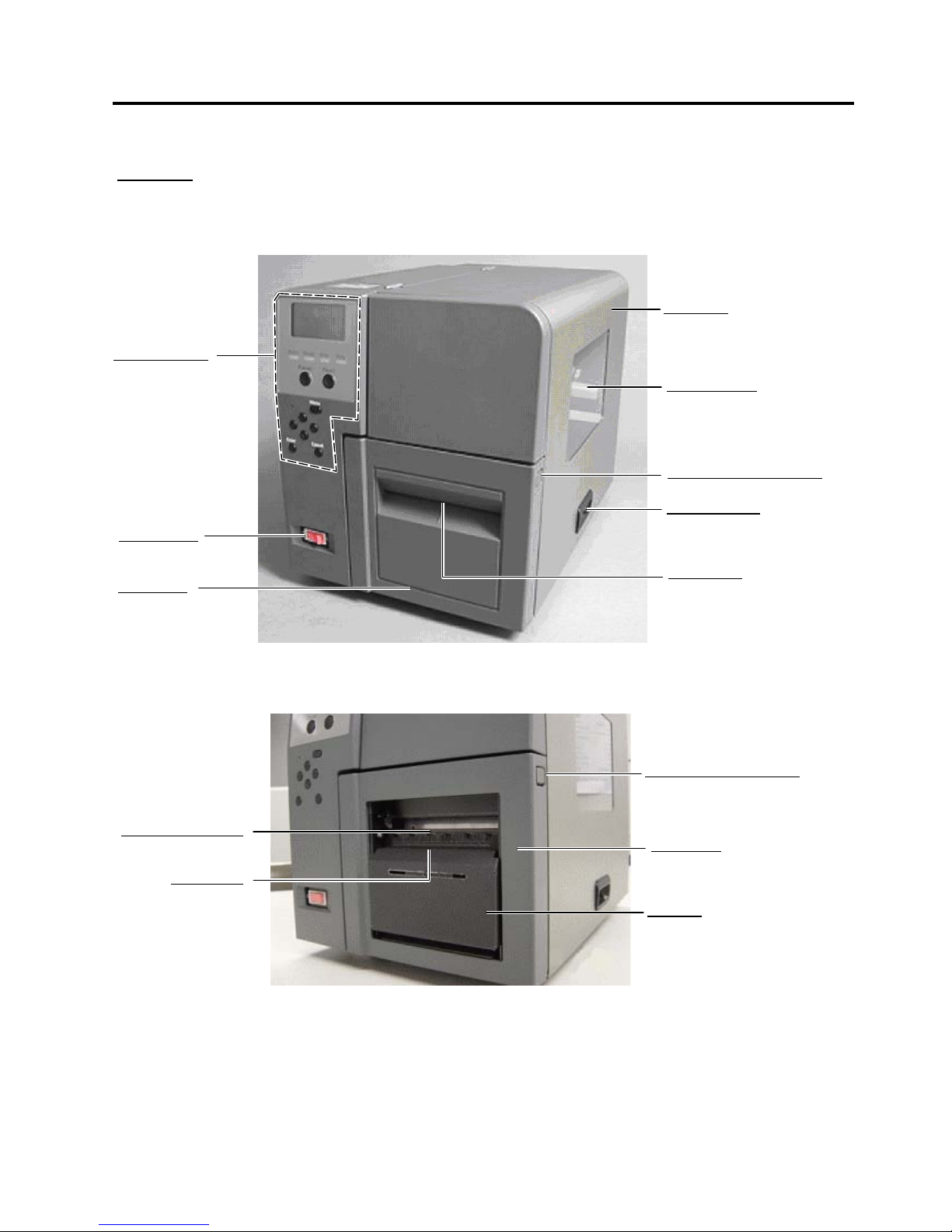
1.3 PART NAMES AND FUNCTIONS
Side Cover
Opened when the media o
r
ribbon is loaded or replaced.
Supply Window
A
remaining quantity of the
media or ribbon can be
checked through the Supply
Window.
Front Cover Unlock Button
Used to open the Front Cover.
Side Cover Grip
Used to open the Side Cover.
Media Outlet
Printed outputs are ejected
through the Media Outlet.
Front Cove
r
Opened when the
media is loaded o
r
replaced.
Power Switch
Used to turn the
p
rinter on/off.
Front View
Standard model or Cutter model
Strip model
Front Cover Unlock Button
Used to open the Front Cover.
Front Cover
Opened when the media is
loaded or replaced.
Strip Unit
Media Holding Roller
Strip Senso
r
Operation Panel
Used to following.
•Select a menu
•Printer Setting
•Display Message
etc.
(For details, refer to
section 1.4)
1. OUTLINE EO10-33021
1.3 PART NAMES AND FUNCTIONS
1-4
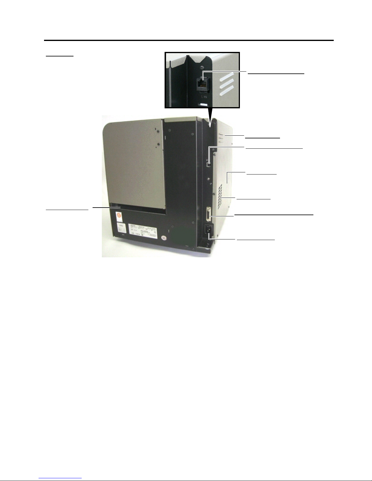
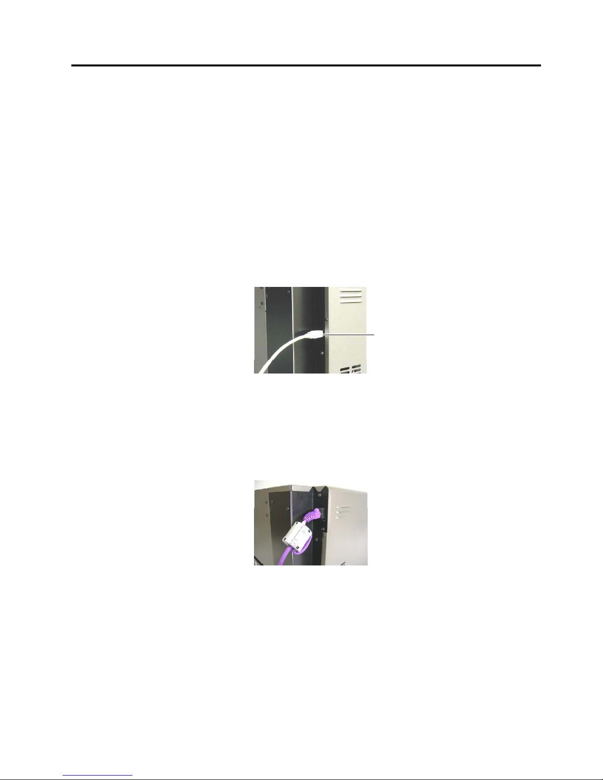
Rear View
USB Interface Connecto
r
Used to connect the printer to a PC
with a USB cable.
(USB Interface model only)
Ventilation Slot
Lets trapped heat pass out of the printer.
Expansion I/O Interface Connecto
r
Used to interface with an external
equipment (Refer to Section 4.)
A
C Power Inlet
Fanfold Paper Slot
A
llows fanfold paper to
feed into the printer from
the printer back.
LAN Interface Connecto
r
Used to connect the printer to a PC
with a LAN cable.
(LAN Interface model only)
Left Side Panel
Reset Switch
Used to reset the print server to the
factory default by the insertion of the
reset pin into the hole.
1. OUTLINE EO10-33021
1.4 OPERATION PANEL
1-5
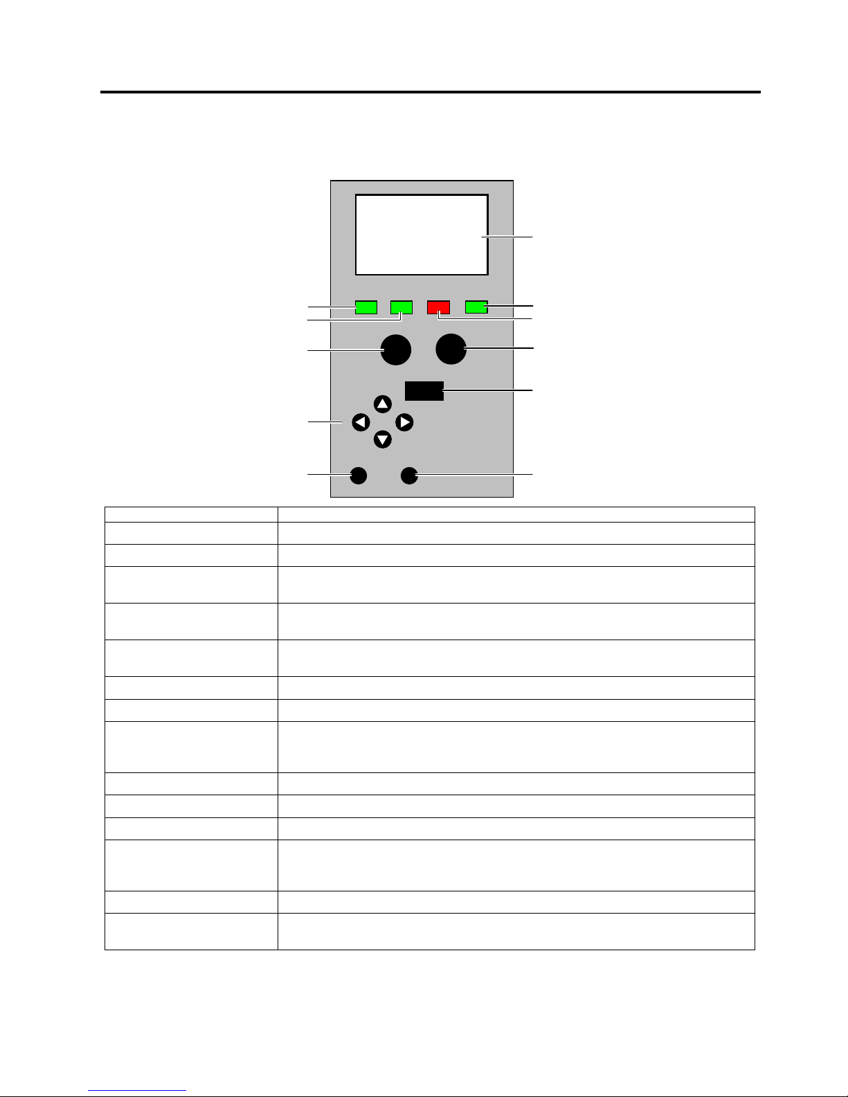
1.4 OPERATION PANEL
The Operation Panel is equipped with the LCD Message Display, which is used to indicate the state of the
printer, 4 LED’s, and 9 keys. Please see the table below for details.
Name Functions (Purposes)
LCD Message Display Shows the menu or error information.
Power LED Illuminates in green when the printer is turned on.
Ready LED Illuminates in green when the printer is ready, and goes out when the printer is in
a pause state or while the menu is being displayed.
Error LED Illuminates in red when an error occurs, and flashes in red in the event of a
warning.
Data LED Flashes in green when data is received, and illuminates in green when data is in
the receive buffer.
[Pause] key Used to place the printer in a pause or ready state.
[Feed] key Used to feed the media for a single page or label length.
[Menu] key Used to display the menu when the printer is in a ready or pause state. When
held down, the [Menu] key will be locked, and when held down again, it will be
unlocked.
◄key
Used to choose an item on the left while the menu is being displayed.
►key
Used to choose an item on the right while the menu is being displayed.
▲key
Used to choose an item above while the menu is being displayed.
▼key
Used to choose an item below while the menu is being displayed.
When the model with the Cutter Unit is used, holding down this key in a ready or
pause state causes the media to be cut.
[Enter] key Used to determine the settings while the menu is being displayed.
[Cancel] key Used to clear an error when it occurs.
When held down, print data is cleared.
LCD Message Display
Error LED
[
Feed]Key
[
Menu] Key
[
Cancel] Key
Ready
No. 00000
Power
Ready
Error Data
Ente
r
Menu
Pause
Feed
Cancel
Data LED
Power LED
Ready LED
[PAUSE] Key
Cursor Keys
(◄ ► ▲ ▼)
[Enter] Key
1. OUTLINE EO10-33021
1.5 DIMENSIONS (APPROXIMATE)
1-6
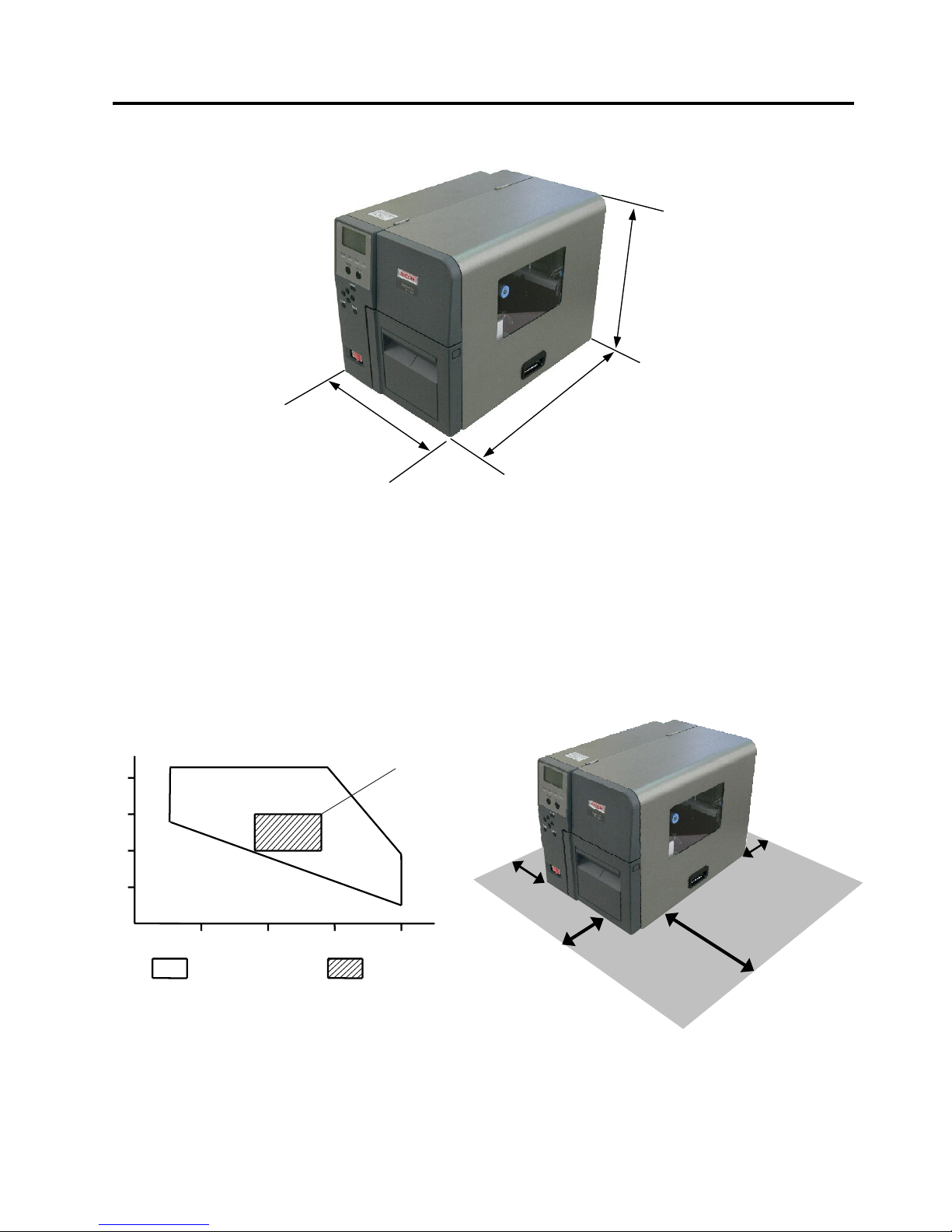
A
cceptable operating
range
Print quality
guaranteed range
10 20 30 40
20
40
60
80
%RH
℃
5℃90%
29℃90%
5℃
55%
40℃39%
40℃10%
18℃
60%
28℃
60%
28℃
40%
18℃
40%
1.5 DIMENSIONS (APPROXIMATE)
1.6 OPERATING ENVIRONMENT
Install the printer in a place where ample space is reserved for the operation. Also, place the printer on a
well ventilated, smooth, level desk or rack specifically designed for the printer. Make sure that the 4 feet of
the printer make full contact with the surface of the desk or rack.
Be sure that there is sufficient space around the printer, as illustrated below.
Depth: 455mm
Width: 300mm
Height: 353.5mm
(including the rubber feet)
Min 15cm
Min 30cm
Min 5cm
Min 10cm
1. OUTLINE EO10-33021
1.7 BASIC SPECIFICATIONS
1-7
1.7 BASIC SPECIFICATIONS
(1) Printing method: Thermal direct printing or thermal transfer printing
(2) Resolutions (dot density): 600 dpi (23.6 dots/mm)
(3) Print speed: Max. 150 mm/second (6ips)
There are limitations on a print speed depending on the media or ribbon
type and an image to print.
Note: Print speed is selectable from 1 ips to 6 ips by the printer driver.
(4) Media alignment: Center
(5) Max. effective print width: 104 mm (Approximate 4”)
(6) Max. print length: 1,000 mm
(7) Available media width: 15 to 120 mm
(8) Host interface: USB model: B-SX600-HS11/HH11/HC11-QM-R
• USB 2.0 High Speed
LAN model: B-SX600-HS12/HH12/HC12-QM-R
• 10BASE-T / 100BASE-TX (IEEE802.3)
• Print Protocol: LPR, PORT9100 (unidirectional), PORT9100
(bi-directional)
• LPR queue name: lp
• Control protocol: HTTP
(9) Operating system: Windows 2000, Windows XP, Windows Server 2003, Windows Vista
(10) Weight: 20.6 kg (USB model: B-SX600-HS11/HH11/HC11-QM-R)
21.0 kg (LAN model: B-SX600-HS12/HH12/HC12-QM-R)
(11) Rating: Input Voltage: 100 VAC to 240 VAC
Frequency: 50/60 Hz (48 to 62 Hz)
Power consumption: 250 W or less under normal operation
20W or less under low power mode operation
Type B

1. OUTLINE EO10-33021
1.8 CUTTER UNIT SPECIFICATIONS (B-SX600-HC11/HC12-QM-R MODEL)
1-8
(12) Noise: 75 dB or less
(13) Operating temperature range: 5 to 40 °C (Print quality guaranteed at temperatures between 18 and 28
°C)
(14) Relative humidity: 10 to 90% (Print quality guaranteed at humidity between 40 and 60%)
(15) Storage temperature range: -20 to 70 °C
(16) Storage humidity range: 5 to 90%
(17) Safety and EMC Standard: CE, TÜV GS, C-Tick, UL, CUL, FCC, ICE, CCC
(18) Environmental standard: RoHS Directive compliant
1.8 CUTTER UNIT SPECIFICATIONS (B-SX600-HC11/HC12-QM-R MODEL)
(1) Acceptable media thickness: 0.08 mm to 0.26 mm
(2) Acceptable label pitch: 10 mm to 1,000 mm
(3) Cut mode: Continuous cut
Cut after printing
Batch cut
(4) Restrictions: Cutting self-adhesive labels is not allowed.
Cutting within 1 mm around perforation is not allowed.
Cutting fabrics or films is not allowed.
Note: The cutter unit is a factory option.
1.9 STRIP UNIT SPECIFICATIONS (B-SX600-HH11/HH12-QM-R MODEL)
(1) Effective print speed: 101.6 mm/second or less (same as a feed speed)
(2) Peeling method: Tensioning
(3) Peeling detection system: A reflective photo sensor is used to detect a label.
(4) Restrictions: Peel-off operation is not allowed when:
Perforated labels are used
Fanfold labels are used.
Fabrics or films are used
Outside wound labels are used
Labels other than rectangular die-cut labels are used.
Note: The strip unit is a factory option.
1. OUTLINE EO10-33021
1.10 MECHANICAL BLOCK
1-9
1.10 MECHANICAL BLOCK
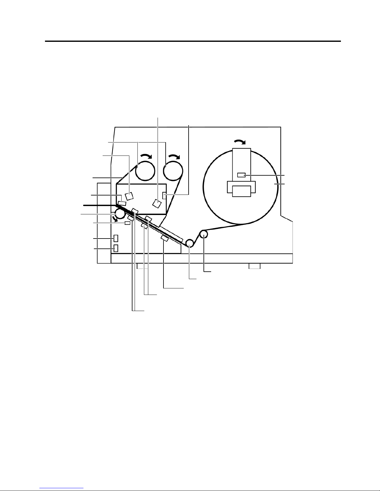
1.10.1 Mechanism
(1) Batch Mechanism (HS11/HS12 model)
This is the standard mechanism which lets the printer print continuously until the number of media specified
in the label issue command has been printed.
Media
Media Near End Sensor
Ribbon End Sensor
Ribbon Encoder Sensor
(Ribbon slit Sensor, Feed)
Ribbon
Ribbon Shaft
Front Cove
r
Open Senso
r
Side Cove
r
Open Senso
r
Media End Sensor
Movable Media Sensor (Feed Gap Sensor),
Reflective Media Sensor (Black Mark Sensor)
Print Head
Ribbon Encoder Senso
r
Ribbon slit Sensor, Take-up)
Print Head
O
p
en Senso
r
Fixed Media Sensor (Feed Gap Sensor)
Platen
Media Roll Damper
Media Roll Guide

1. OUTLINE EO10-33021
1.10 MECHANICAL BLOCK
1-10
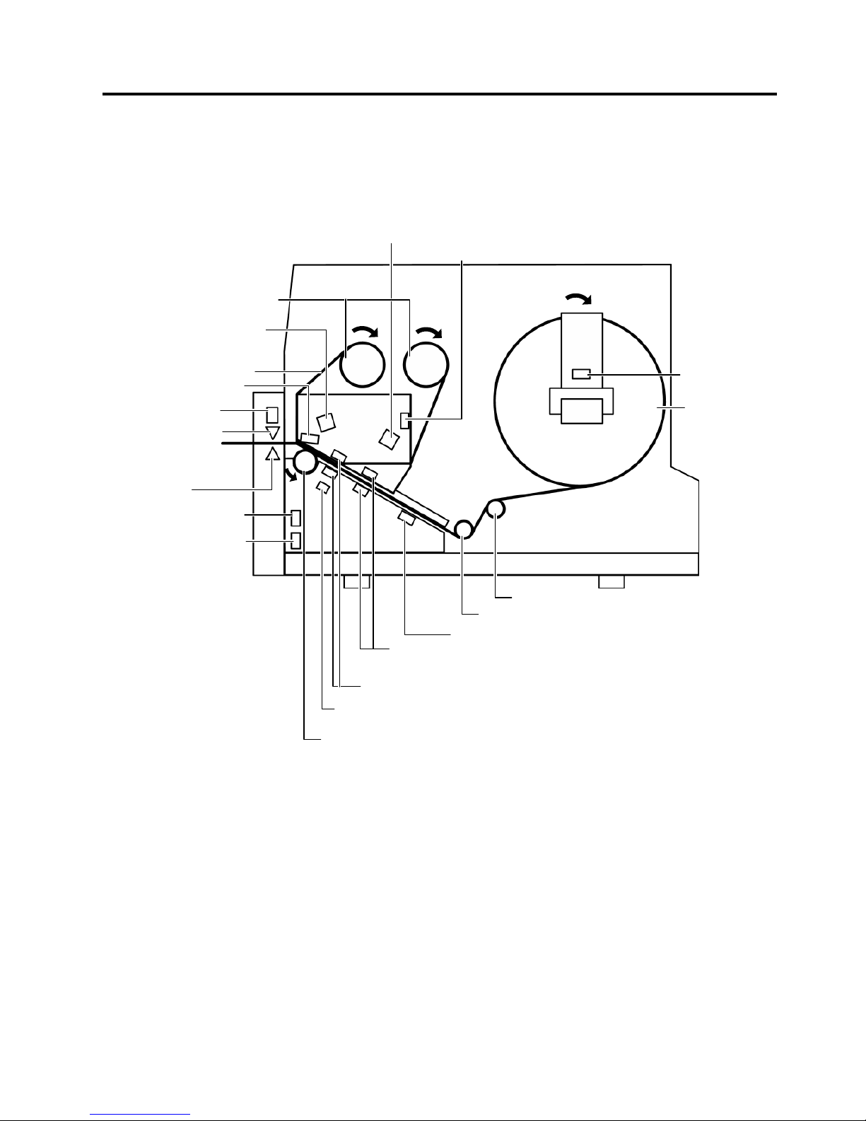
(2) Strip Mechanism (HH11/HH12 model)
When an factory optional strip module is attached, a label is stripped from the backing paper by the strip
shaft, and the backing paper is drawn into the strip module. The nextlabel will not be printed until the
preceding label is removed, as a presence of the label at the strip shaft is monitored by the strip sensor.
Media
Media Near End Sensor
Ribbon End Sensor
Ribbon
Ribbon Shaft
Front Cove
r
Open Senso
r
Feed Roller (Black)
Media End Sensor
Print Head
Print Head Open Sensor
Platen
Pinch Roller (White)
Strip senso
r
Backing Pape
r
Side Cove
r
Open Senso
r
Media Holding
Rolle
r
Media Roll Damper
Media Roll Guide
Strip Plate
Movable Media Sensor (Feed Gap Sensor),
Reflective Media Sensor
(
Black Mark Sensor
)
Fixed Media Sensor (Feed Gap Sensor)
Ribbon Encoder Sensor
(Ribbon slit Sensor, Feed)
Ribbon Encoder Senso
r
Ribbon slit Sensor, Take-up)
1. OUTLINE EO10-33021
1.10 MECHANICAL BLOCK
1-11
3) Cutter Mechanism (HC11/HC12 model)
When an factory optional Cutter module is attached, printed media is fed to the cutter unit and cut off from
the media roll.
Media
Media Near End
Sensor
Ribbon End Sensor
Ribbon
Ribbon Shaft
Front Cove
r
Open Senso
r
Media End Sensor
Print Head
Print Head Open Sensor
Platen
Cutter Blade
Media Roll Damper
Media Roll Guide
Side Cove
r
Open Senso
r
Cutter Carriage
Position Senso
r
Cutter Carriage Unit
Transmissive Media Edge Sensor (Feed Gap Sensor, Movable)
Reflective Media Sensor (Black Mark Sensor)
Transmissive Media Center Sensor (Feed Gap Sensor, Fixed)
Ribbon Encoder Sensor
(Ribbon slit Sensor, Feed)
Ribbon Encoder Senso
r
(Ribbon slit Sensor, Take-up)
 Loading...