

Page 1

PRINTED IN JAPAN
TOSHIBA Thermal Printer
B-SA4T SERIES
Document No. EO10-33016A
Original Jul., 2005
(Revised Sep., 2005)
Product Description
Page 2

EO10-33016A
(Revision Date: Feb. 14, 2008)
TABLE OF CONTENTS
Page
1. OUTLINE -------------------------------------------------------------------------------------------------1- 1
1.1 Printer Specifications--------------------------------------------------------------------------------------1- 1
1.2 Description of Model Number---------------------------------------------------------------------------1- 1
1.3 Appearance and Dimensions (Approximate) -------------------------------------------------------1- 2
1.3.1 Front View/Rear View ---------------------------------------------------------------------------1- 2
1.3.2 Operation Panel-----------------------------------------------------------------------------------1- 2
1.3.3 Dimensions (Approximate)---------------------------------------------------------------------1- 2
1.3.4 Weight-----------------------------------------------------------------------------------------------1- 2
1.4 Basic Specifications ---------------------------------------------------------------------------------------1- 3
1.5 Electronics Specifications--------------------------------------------------------------------------------1- 7
2. SUPPLY SPECIFICATIONS-------------------------------------------------------------------------2- 1
2.1 Media --------------------------------------------------------------------------------------------------------2- 1
2.2 Ribbon --------------------------------------------------------------------------------------------------------2- 5
2.3 Care and Handling of the Media and Ribbon -------------------------------------------------------2- 6
2.4 Specification of RFID Tag --------------------------------------------------------------------------------2- 7
3. OPTIONAL KIT -----------------------------------------------------------------------------------------3- 1
3.1 Cutter Module: B-SA204-QM/B-SA204-QM-R------------------------------------------------------3- 1
3.2 Strip Module: B-SA904-H-QM-R -----------------------------------------------------------------------3- 2
3.3 Serial Interface Board: B-SA704-RS-QM-R---------------------------------------------------------3- 3
3.4 Wireless LAN Board: B-SA704-WLAN-QM----------------------------------------------------------3- 4
3.5 300-Dpi Print Head: B-SA704-TPH3-QM-R---------------------------------------------------------3- 8
3.6 Expansion I/O Board: B-SA704-IO-QM-R -----------------------------------------------------------3- 8
3.7 Real Time Clock: B-SA704-RTC-QM-R--------------------------------------------------------------3- 9
3.8 RFID Module: B-SA704-RFID-U2-EU-R ------------------------------------------------------------ 3-10
CAUTION!
1. This manual may not be copied in whole or in part without prior written permission of TOSHIBA
TEC.
2. The contents of this manual may be changed without notification.
3. Please refer to your local Authorised Service representative with regard to any queries you
may have in this manual.
Copyright © 2005
by TOSHIBA TEC CORPORATION
A
ll Rights Reserved
570 Ohito, Izunokuni-shi, Shizuoka-ken, JAPAN
NOTE:
Though the pictures used in this document are mostly those of the B-SA4TM (Metal cover model), the
replacement procedures are in common with the B-SA4TP (Plastic cover model).
[B-SA4TM] [B-SA4TP]
Page 3

1. OUTLINE EO10-33016A
1.1 Printer Specifications
1- 1
1. OUTLINE
1.1 Printer Specifications
1) Various bar codes, characters and graphic data can be printed using both thermal transfer and thermal
direct methods. This printer can also print writable characters and logos at designated coordinates by
using a graphic command.
2) Centronics, LAN, and USB are provided as standard interfaces for communicating with a PC.
Additionally, serial interface and wireless LAN interface are optionally available.
3) A 32-bit CPU and a Field Programmable Gate Array (FPGA) equipped with several peripheral LSIs
realizes high system performance.
4) An area required to place a printer is about A4 size, in spite of both media and ribbon being loaded
inside it. Also, the Top Cover is opened upward, which saves the installation space.
5) Clear print is realized by an 8 dots/mm (203 dpi) (GS12 model) or 11.8 dots/mm (300 dpi) (TS12 model)
print head, at a printing speed of 50.8 mm/sec. (2 inches/sec.), 101.6 mm/sec. (4 inches/sec.), or 152.4
mm/sec. (6 inches/sec.)
6) As the enclosure is made of metal, the printer can be used in an industrial environment such as a factory.
7) Design of the printer is simple. Especially, attachment and removal of the print head and platen are very
simple, which makes maintenance easy.
8) Optional cutter module or optional strip module will expand the application of the printer .
NOTE: Every size is written in millimeter (mm) in this manual. To obtain the size in inch, divide by 25.4.
1.2 Description of Model Number
B – S A 4 T M – G S 1 2 – Q M - R
RoHS compliant
Destination Code
QM: Standard for Worldwide
CN: China
Machine Type
Machine Version
Issue mode
S: Batch
Resolution
G: 8 dots/mm (203 dpi)
T: 11.8 dots/mm (300 dpi)
Material of enclosure
M: Metal
P: Plastic
Printing method:
T: Thermal direct or Thermal transfer
Printing width
4: 4 inches
Page 4
1. OUTLINE EO10-33016A
1.3 Appearance and Dimensions (Approximate)
1- 2
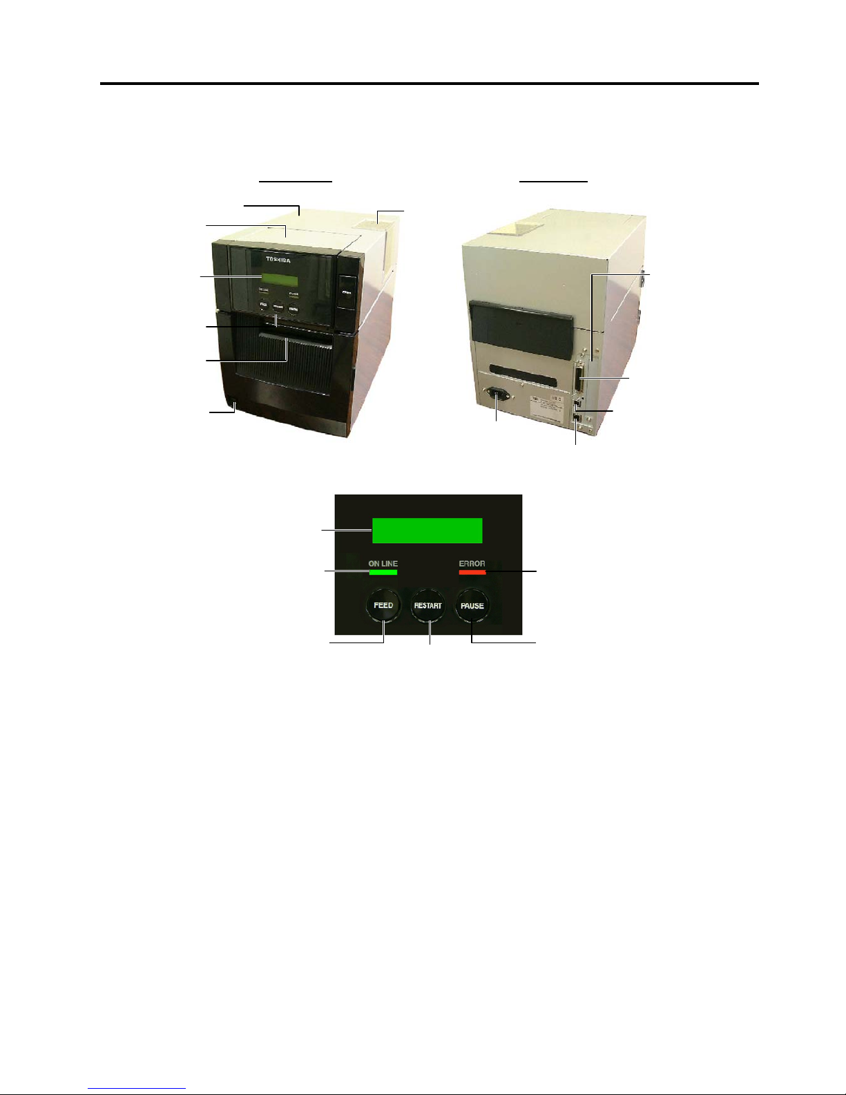
1.3 Appearance and Dimensions (Approximate)
1.3.1 Front View/Rear View
Front View Rear View
1.3.2 Operation Panel
LCD Message Display: When the power is turned on and it is ready to print, ON LINE is displayed.
ON LINE LED (Green): 1) Flashes when communicating with a host PC.
2) Lights while printing.
ERROR LED (Red): Lights when the printer is in an erroneous state.
FEED key: Feeds media.
RESTART key: Resets the printer when paused or when an error occurs.
Used to set a threshold. (Refer to the Owner’s Manual.)
PAUSE key: Pauses printing.
Message display shows PAUSE and a remaining count.
Used to set a threshold (Refer to the Owner’s Manual.)
1.3.3 Dimensions (Approximate)
B-SA4TM (Metal cover type): 238 mm (W) x 402 mm (D) x 332 mm (H)
B-SA4TP (Plastic cover type): 238 mm (W) x 339 mm (D) x 332 mm (H)
1.3.4 Weight
B-SA4TM (Metal cover type): 15Kg
B-SA4TP (Plastic cover type): 12Kg
L
CD Message
Display
Operation
Panel
Media Outlet
Top Cover
Supply Window
Power Switch
{: OFF
|: ON
LAN Connector
Ribbon Cover
Parallel Interface
Connector (Centronics)
Serial Interface
(Option),
Wireless LAN
interface (Option)
AC Power Inlet
USB Connector
LCD Message Display
ON LINE LED (Green)
ERROR LED (Red)
[PAUSE] key
[FEED] key
[RESTART] key
Page 5

1. OUTLINE EO10-33016A
1.4 Basic Specifications
1- 3
1.4 Basic Specifications
1) Printing method: Thermal direct printing or thermal transfer printing
2) Print head
GS12 model TS12 model
Total number of dots 832 dots 1248 dots
Dot density 8 dots/mm 11.8 dots/mm
Effective print width 104 mm 105.7 mm
Thermal pitch 0.125 mm 0.0847 mm
3) Print speed: 6”/sec., 4”/sec., 2”/sec.
NOTE: These print speeds are available when printing ratio is less than 30% of the entire label or tag paper.
4) Format size (W) x (L)
GS12 model: Max. 104.0 mm x 997.0 mm
TS12 model: Max. 105.7 mm x 997.0 mm
5) Issue mode
• Batch
• Auto cut (Auto cut mode is available only when the optional cutter is attached.)
• Strip (Strip mode is available only when the optional strip module is attached.)
6) Type of bar code/two dimensional code
(1) JAN8, EAN8, J AN13, EAN13, UPC-A, UPC-E
(15) Industrial 2 of 5
(2) EAN8, EAN13, UPC-A, UPC-E + 2digit (16)
Customer Bar Code
(3) EAN8, EAN13, UPC-A, UPC-E + 5digit Postal code for Japan)
(4)
NW-7
(17)
POSTNET (Postal code for USA)
(5)
CODE39 (STANDARD)
(18)
RM4SCC (Postal code for UK)
(6)
CODE39 (FULL ASCII)
(Royal Mail 4 State Customer Code)
(7)
ITF
(19)
KIX CODE (Postal code for Belgium)
(8)
MSI
(20)
Maxi Code
(9) CODE93 (21)
Micro PDF417
(10)
CODE128 (Automatic code change) (22) CP CODE
(11)
EAN128
(23)
RSS14
(12)
Data Matrix (24) High priority customer bar code
(13)
PDF417 (25) GTIN (Global Trade Item Number)
(14)
QR Code
7) Bar code rotation: 0
°, 90°, 180°, 270°
Page 6
1. OUTLINE EO10-33016A
1.4 Basic Specifications
1- 4
8) Magnification of bar code
UPC/EAN/JAN/CODE93/128/PDF417............Up to 6 modules can be automatically calculated using
1-module width designation (1 to 15 dots).
Dots/Module
Bar code
2 3 4 5 6 7 8
Min. Module Width (mm)
0.25 0.38 0.50 0.63
– – –
UPC-A/E
EAN8/13
JAN8/13
Magnification (times)
0.76 1.14 1.51 1.91
– – –
CODE93
EAN128
CODE128
PDF417
Min. Module Width (mm)
0.25 0.38 0.50 0.63 0.75 0.88 1.00
Dots/Module
Bar code
9 10 11 12 13 14 15
Min. Module Width (mm)
– – – – – – –
UPC-A/E
EAN8/13
JAN8/13
Magnification (times)
– – – – – – –
CODE93
EAN128
CODE128
1.13 1.25 1.38 1.50 1.63 1.75 1.88
PDF417
Min. Module Width (mm)
1.13 1.25
– – – – –
NW-7/CODE39/ITF/MSI/Industrial 2 of 5 .......The width of narrow bars, wide bars and spaces can be
optionally changed in a range of 1 to 99 dots.
Data Matrix.......................................................The width of one cell can be changed in a range of 1 to
99 dots.
9) Type of characters
(1) Times Roman medium (12, 15 point) (9) Prestige Elite medium (10.5 point)
(2)
Times Roman bold (15, 18, 21 point) (10) Prestige Elite bold (15 point)
(3)
Times Roman Italic (18 point) (11) Courier medium (15 point)
(4)
Helvetica medium (9, 15, 18 point) (12) Courier bold (18 point)
(5)
Helvetica bold (18, 21 point) (13) OCR-A, B (12 point)
(6)
Helvetica Italic (18 point) (14) Outline font (Helvetica bold, Helvetica bold proportional,
(7) Presentation bold (27 point) Price Font (1,2,3), Times roman proportional, Pop
(8)
Letter Gothic medium (14.3 point) Proportional, Proportional)
(15)
Writable characters (2-byte character is available.)
10) Character code
(1) PC-850 (2) PC-8 (3) PC-852 (4) PC-857 (5) Arabic (6) LATIN 9 (7) PC-1257 (8) PC-1254
(9) PC-1253 (10) PC-1252 (11) PC-1251 (12) PC-1250 (13) PC-855 (14) PC-851 (15) PC-866
11) Character magnification
(1) Regular font: 0.5 to 9. 5 t imes (magnified by 0.5 times in each direction)
(2) Outline font: 2.0 to 85.0 mm (magnified 0.1 mm in each direction)
NOTE: When the outline font size is large, the ribbon may wrinkle according to the quality of the ribbon or
print tone.
Page 7
1. OUTLINE EO10-33016A
1.4 Basic Specifications
1- 5
12) White or black background all types of characters are available.
13) Character rotation: 0
°, 90°, 180°, 270°
14) Character strings rotation: 0
°, 90°, 180°, 270°
15) Type of line
(1) Horizontal line (2) Vertical line (3) Slant line (4) Square (5) Rounded Rectangle (6) Circle
16) Line Width: 0.1 to 9.9 mm can be specified (in units of 0.1 mm)
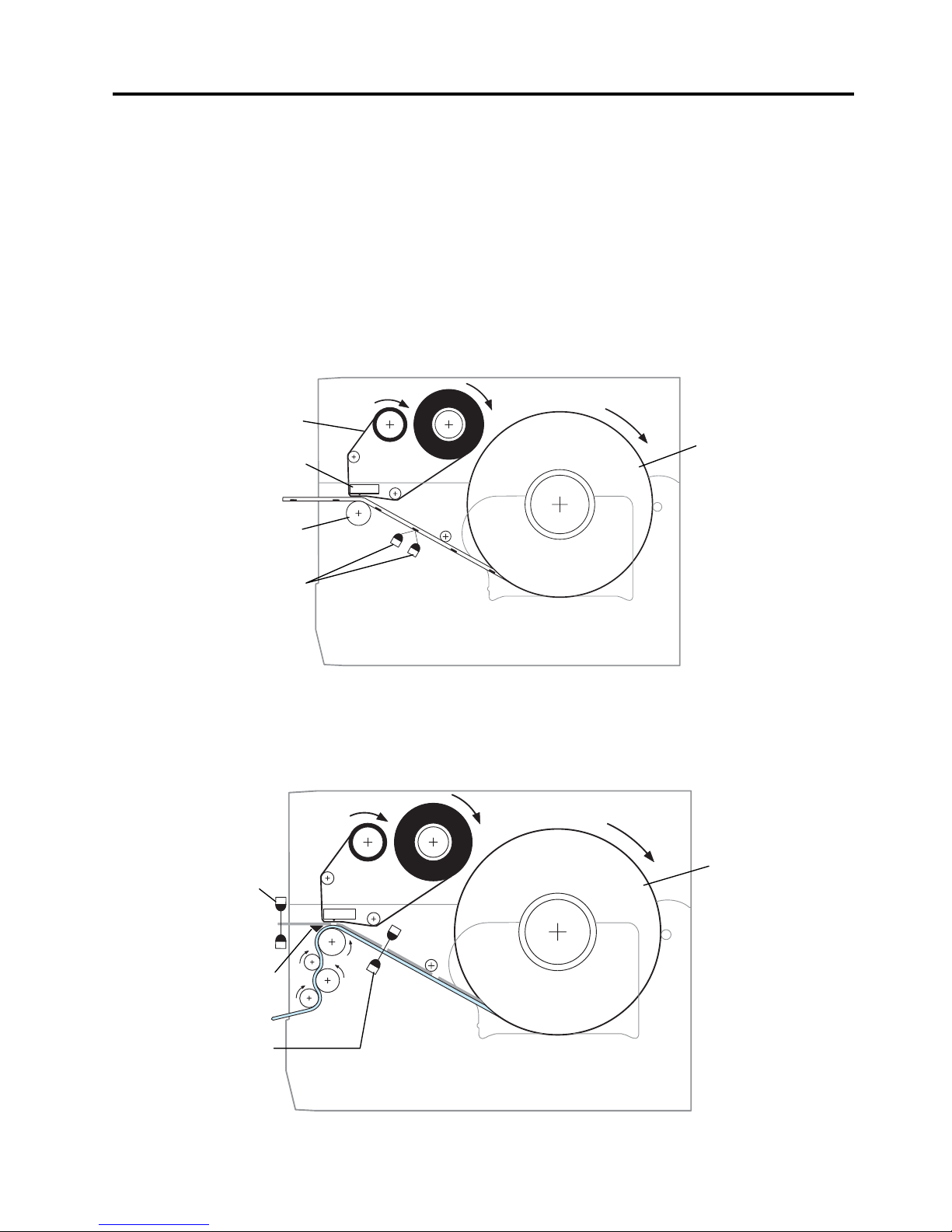
17) Mechanism
(1) Batch mechanism
This is the standard mechanism which lets the printer print continuously until the number of media
specified in the label issue command has been printed.
(2) Strip mechanism (Option)
When an optional strip module is attached, a label is stripped from the backing paper by the strip
shaft, and the backing paper is drawn into the strip module. The next label will not be printed until
the preceding label is removed, as a presence of the label at the strip shaft is monitored by the strip
sensor.
Ribbon
Print Head
Platen
Black Mark Sensor
Tag Stock
Strip Sensor
Strip Shaft
Feed Gap Sensor
Label Stock
Page 8
1. OUTLINE EO10-33016A
1.4 Basic Specifications
1- 6
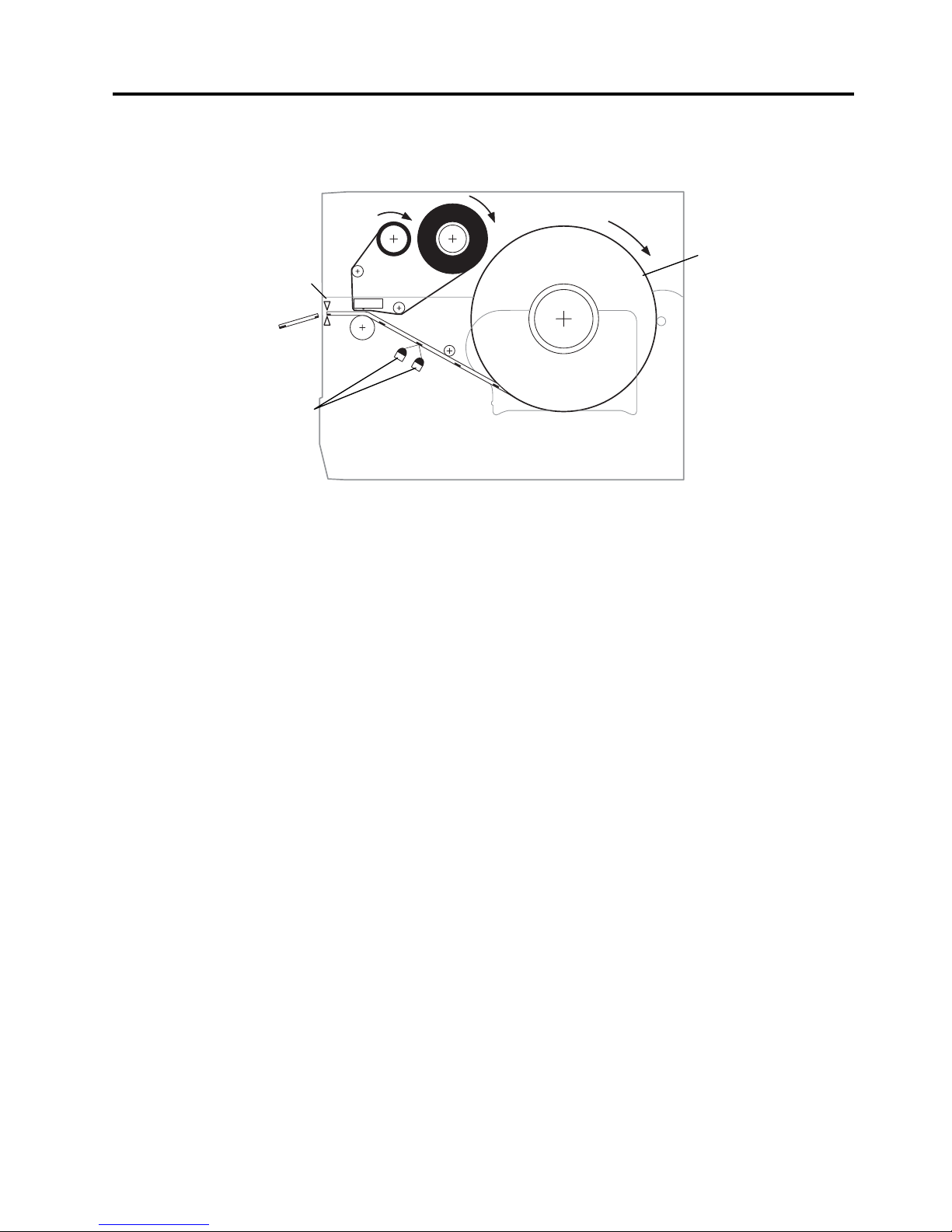
(3) Auto cut mechanism (Option)
When an optional cutter module is attached, printed media is fed to the cutter unit and cut off from
the media roll.
18) Power supply
Universal power supply: AC100 to 240 V ±10%, 50/60Hz
Harmonics: Class A
19) Power consumption
During a print job: 2.1A (100V) to 1.1A (240V), 155W rating
During standby: 0.19A (100V) to 0.15A (240V), 13W (100V) to 22W (240V)
20) Rush current
100V input: 10A
240V input: 22A
NOTE: Be sure to use an exclusive power outlet for the printer.
21) Operating temperature range
Thermal direct:: 0°C to 40°C
Thermal transfer: 5°C to 40°C
22) Relative humidity
25% to 85%RH (no condensation)
Cutter
Black Mark Sensor
Tag Stock
Page 9
1. OUTLINE EO10-33016A
1.5 Electronics Spec i fications
1- 7
1.5 Electronics Specifications
1) CPU: HD6417705F133BV
2) Memory
(1) Program: 16-MB Flash ROM
(2) Backup: 512-byte EE-PROM
(3) Image buffer + Work: 16-MB SD-RAM
3) Interface
(1) Parallel interface (Standard interface)
c Centronics interface conforming to IEEE1284, supporting SPP mode (compatibility mode) and
nibble mode.
d Data input method: 8-bit parallel (DATA 1 to 8)
e Control signals
Compatibility mode
nStrobe, nAck, Busy, PError, Select, nAutoFd, nInit, nFault, nSelectIn
Nibble mode HostClk, PtrClk, PtrBusy, AckDataReq, Xflag, HostBusy, nInit, nDataAvail,
IEEE1284Active
f Data input code: ASCII, JIS 8-bit code for European characters, 8-bit code for graphic
g Receiving buffer: 1MB (shared with other interfaces)
h Input/Output circuit configuration and Input/Output conditions
Type
Signal Name
Configuration
Input/
Output
Data 1 to 8
SN74LVX161284 or equivalent
1K
+5V
Input
nStrobe/HostClk
nInit/nReverseRequest
nAutoFd/HostBusy/HostAck
nSelectIn/IEEE1284Active
SN74LVX161284 or equivalent
1K
+5V
100P
Output
Busy/PtrBusy/PeriphAck
nFault/nDataAvail/nPeriphRequest
nAck/PtrClk/PeriphClk
Select/XFlag
PError/AckDataReq/nAckReverse
SN74LVX161284
or equivalent
+5V
1K
100P
Logical level
(input)
"1" = 2~5V
"0" = 0~0.4V
Logical level
(output)
"1" = 2.4~5V
"
0" = 0~0.4V
Page 10
1. OUTLINE EO10-33016A
1.5 Electronics Spec i fications
1-8
i Pin Layout (IEEE1284-B Connector)
Signal PIN
No.
SPP Mode Nibble Mode
1 nStrobe HostClk
2 Data 1 Data 1
3 Data 2 Data 2
4 Data 3 Data 3
5 Data 4 Data 4
6 Data 5 Data 5
7 Data 6 Data 6
8 Data 7 Data 7
9 Data 8 Data 8
10 nAck PtrClk
11 Busy PtrBusy
12 PError AckDataReq
13 Select Xflag
14 nAutoFd HostBusy
15 NC NC
16 0V 0V
17 CHASSIS GND CHASSIS GND
18 +5V (For detection) +5V (For detection)
19 TWISTED PAIR GND(PIN1) TWISTED PAIR GND(PIN1)
20 TWISTED PAIR GND(PIN2) TWISTED PAIR GND(PIN2)
21 TWISTED PAIR GND(PIN3) TWISTED PAIR GND(PIN3)
22 TWISTED PAIR GND(PIN4) TWISTED PAIR GND(PIN4)
23 TWISTED PAIR GND(PIN5) TWISTED PAIR GND(PIN5)
24 TWISTED PAIR GND(PIN6) TWISTED PAIR GND(PIN6)
25 TWISTED PAIR GND(PIN7) TWISTED PAIR GND(PIN7)
26 TWISTED PAIR GND(PIN8) TWISTED PAIR GND(PIN8)
27 TWISTED PAIR GND(PIN9) TWISTED PAIR GND(PIN9)
28 TWISTED PAIR GND(PIN10) TWISTED PAIR GND(PIN10)
29 TWISTED PAIR GND(PIN11) TWISTED PAIR GND(PIN11)
30 TWISTED PAIR GND(PIN31) TWISTED PAIR GND(PIN31)
31 nInit nInit
32 nFault NDataAvail
33 0V 0V
34 NC NC
35 NC NC
36 nSelectIn IEEE1284Active
IEEE1284-B Connector
Page 11

1. OUTLINE EO10-33016A
1.5 Electronics Spec i fications
1-9
j Input/Output Signals
Signal I/O Description
Data1 to 8 Input z Input data signals for the 1st to 8th bits.
z Logic 1 is “High” level.
z Min. data pulse width of 2.5 µsec.
nStrobe Input z Synchronizing signal for reading the above data.
z Normally at “High” level. The data is read at the rise of the Low level pulse.
z Minimum data pulse width of 0.5 µsec.
Busy Output
z This signal indicates that the printer is in a Busy state.
z When initialized after the power is turned on
, the printer becomes ready to
receive data and turns the signal to “Low” level.
z
The signal turns to “Hig h” level (in a Busy state) when data is set fr om the
host (at the fall of the nStrobe signal).
z The signal turns to “Low” level when the printer reads the data.
z When the free space of the receive buffer becomes
512 bytes or less, the
printer keeps the sign al at “High” level ( in a Bus y state) for 10 seconds when
data is set from the host, to extend the data read interval.
z When the receive buffer has become full
, the printer stops reading data.
When data is set from the host, t
hen, it keeps the si gnal at “High” leve l (in a
Busy state) until the receive buffer has a free space.
z T he signal is kept at “High ” level (in a Busy sta te) until one of the f
ollowing
states is cleared.
• PAUSE state caused by the [PAUSE] key
• Paper end state
• Ribbon end state
• Head open state
• Printer error state
z Initialization in progress upon receipt of the nInit signal
nAck Output
z This s ignal indicates that t he p
rinter has read the data set by the host and is
ready to receive the next data.
z
The signal is normally at “High”. It is at “Low” for about 5 µsec. after the fall of
the BUSY signal. The ho st should usually set data after the ACK s ignal is
turned from “Low” to “High”.
z
If the nAck signal is ignored and th e next data is s et while the nAck signal is
Low, the “LOW ” level continues about f urther 5 µsec at the fall of the BUSY
signal. However, the data can be received properly.
nInit Input z Reset request signal from the host.
z Normally at “High” level. An input of this signal at “Low” level
causes the
printer to be initialized in the same manner as when the power is turned on.
*
When “Reset process when the nInit signal is ON” is set to “OFF” in the
pa
rameter setting in the sys tem mode, the printer is not initialized even if it
receives this signal at low level.
z
When the nInit signa l is input during pr inting, the printer completes print ing
one tag/label which is being printed, cancels the next process
ing, then is
initialized in the same manner as when the power is turned on.
*
When “Reset process when the nInit signal is ON” is set to “OFF” in the
parameter setting in the s ystem mode, the next pr ocess proceeds without
being canceled.
z Minimum pulse width of 0.5 µsec.
SPP mode
Page 12

1. OUTLINE EO10-33016A
1.5 Electronics Spec i fications
1-10
Select Output
z This is an output sign al which indicat es whether the p rinter is in Pa use state
or placed online. The printer can receive data while placed online.
z The signal is at “Low” level while the printer is in a Pause state.
z
The signal is k ept at “Low” level ( in a Pause stat e) until one of the following
states is cleared.
• Pause state caused by the [PAUSE] key
• Paper end state
• Ribbon end state
• Head open state
• Printer error state
• Initialization in progress upon power on or receipt of the nInit signal
nFault Output
z Output signal indicating that the printer is in a Fault state.
z At “Low” level while the printer is in a Fault state.
z T he signal is kept at “Low” level (in a Fault s tate) until one of the followi
ng
states is cleared.
• Pause state caused by the [PAUSE] key
• Paper end state
• Ribbon end state
• Head open state
• Printer error state
• Initialization in progress upon power on or receipt of the nInit signal
Perror Output
z Output signal indicating a label end or ribbon end state.
z At “High” level when the printer is in a label end or ribbon end state.
z Turns to “Low” level when the label end or ribbon end state is cleared.
+5V ---- z This is not a signal but a +5 V power supply voltage.
z The maximum current of 500 mA can be taken out.
nSelectIn Input Not used
nAutoFd Input Not used
Signal I/O Description
PtrClk Output
z Reverse data transfer phase:
It is used for evaluating data sent to the
host.
z Reverse idle phase: When the printer changes the signal from
Low to High, an interrupt i nforming the host
that the data is available, occurs
PtrBusy Output
z Reverse data transfer phase:
Data bit 3 is used f or the fi rst transfer. Data
bit 7 is used for the second transfer.
Indicates
the forward channel is in a Busy
state.
AckDataReq Output
z Reverse data transfer phase:
Data bit 2 is used f or the fi rst transfer. Data
bit 6 is used for the second transfer.
z Reverse idle phase:
This signal is set to high until the data
transfer is
requested by the h ost. Then, the
process is performed according to the
nDataAvail signal.
Xflag Input z Reverse data transfer phase:
Data bit 1 is used f or the fi rst transfer. Data
bit 5 is used for the second transfer.
Nibble mode
Page 13

1. OUTLINE EO10-33016A
1.5 Electronics Spec i fications
1-11
HostBusy Input
z Reverse data transfer phase:
It indicates that the host can receive data
from the printer by setting the signal to low.
Then, the host sets the signa l to high, and
sends the Ack indicating th at the nibb le data
is received. When the signal is set to low
after one reve
rse channel data transfer is
performed, the interface phase changes to
the idle phase. At that time, there is no
available data on the printer.
z Reverse idle phase:
When this signal is set to high according to
the low pulse of t he PtrClk signal, the host
enters the reverse data transfer phase
again. If this signal is se t to high when the
IEEE1284 Active signal is low, the
IEEE1284 idle phase stops, and the
interface enters the Compatibility mode.
nDataAvail Output
z Reverse data transfer phase: When the signal is low, it indicates the
printer has data to be sent to the host. And
it is used for sending data bits 0 and 4.
z Reverse idle phase: It is used for indicating that the data is
available.
Page 14
1. OUTLINE EO10-33016A
1.5 Electronics Spec i fications
1-12
(2) USB (Standard interface)
c Standard: Conforming to Rev. 2.0
d Transfer type: Control transfer, Bulk transfer
e Transfer rate: Full speed (12M bps)
f Transfer control method: Data transfer is controlled by sending/receiving a status with the receive
buffer free space information.
g Receiving buffer: 1MB (shared with other interface)
(3) LAN interface (Standard interface)
c Constitution: 10 Base-T or 100 Base-TX LAN controller
d Protocol: TCP/IP
e Network specifications:
Function Description
LPR Server Function Supporting LPR protocol (Line Printer Daemon Protocol) which enables
printing via TCP/IP network.
WEB printer f unction When the printer is connected to a PC via TCP/IP network, browsin g the
printer status, issuin g media, checking or changing t he printer settings, or
downloading the firmware are enabled.
Socket communication
protocol
Socket is an end point of a connection to other host computer via TCP/I P
network, which is used to send/receive data between the PC and the
printer.
Use of Socket Communication protocol allows a communication only by
reading/writing data to/from the socket.
E-mail function Commands are sent to the printer by an e-mail. This function allows
remote control of the printer.
f Receiving buffer: 1MB (shared with other interface)
(4) Serial interface (Optional interface)
A serial interface conforming to RS-232C is available when an optional serial interface board, B-
SA704-RS-QM-R, is installed in the printer.
c Communication mode: Full-duplex
d Transmission speed: 2400,4800,9600,19200, 38400, 115200 bps (selectable)
e Synchronization: start- st op synchronization
f Transmission parameter
Parity: None, EVEN, ODD
Start bit: 1-bit
Stop bit: 1-bit or 2-bit
Word length: 7-bit or 8-bit
g Error detection
Parity check: VRC (Vertical Redundancy Checking)
Framing error: This error occurs when no stop bit is found in the frame specified starting with
the start bit.
h Data entry code: ASCII, 8-bit code for European characters, 8-bit code for graphic
i Receiving buffer: 1MB (shared with other interface)
j Protocol: No-procedure method
CAUTION!
Do not directly connect the LAN cable wired
outside of a building to the LAN port provided on this product, as the LAN port on
this product is intended for indoor connection.
To connect such LAN cable to the product, be sure to use any communication equipment, like a router, a hub, or a modem
which
is located within the same building as the product.
Page 15

1. OUTLINE EO10-33016A
1.5 Electronics Spec i fications
1-13
k Flow control
XON/XOFF (DC1/DC3) pr otocol
This is a software flow control using XON (DC1)/XOFF (DC3) code.
• When initialized after power on, this printer becomes ready to receive data and sends an
XON code (11H). (Transmission or non-transmission of XON code is selectable by means of
the parameter setting.)
• The printer sends an XOFF code (13H) when the free area in the receive buffer becomes
10K Bytes or less.
• The printer sends an XON code (11H) when the free area in the receive buffer are 512KB or
more.
• When there is no free area in the receive buffer, the printer discards received data which
exceeds the receive buffer capacity without storing it in the buffer. (After detect ing the XOFF
code, the host computer must stop transmission before the printer receive buffer becomes
full.)
• The printer sends an XOFF code (13H) at power off time. (Transmission or non-transmission
of XOFF code is selectable with the parameter setting.)
• The DTR signal is always “High” level (Ready).
• The RTS signal is always “High” level (Ready).
READY/BUSY (DTR) protocol
This is a hardware flow control using DTR signal as a control code.
• When initialized after power on, this printer becomes ready to receive data and conv ert s t he
DTR signal to "High" level (READY).
• The printer converts the DTR signal to "Low" level (BUSY) when the free area in the receive
buffer amount to 10K bytes or less.
• The printer converts the DTR signal to "High" level (READY) when the free area in the
receive buffer amount to 512KB or more.
• When there is no free area in the receive buffer, the printer discards received data which
exceeds the receive buffer capacity without storing it in the buffer. (After detect ing a BUSY
signal, the host computer must stop transmission before the printer receive buffer becomes
full.)
• The RTS signal is always “High” level.
XON/XOFF (DC1/DC3) pr otocol + READY/BUSY (DTR) protocol
This is a software and hardware flow control using XON/XOFF code and DTR signal.
• When initialized after power on, this printer becomes ready to receive data and conv ert s t he
DTR signal to "High" level (READY). The printer sends an X O N code (11H).
• When the free area in the receive buffer are 10K bytes or less, the printer converts the DTR
signal to "Low" level (BUSY) and sends an XOFF code (13H).
• When the free area in the receive buffer are 512KB or more, the printer converts the DTR
signal to "High" level (READY) and sends an XON code (11H).
• When there is no free area in the receive buffer, the printer discards received data which
exceeds the receive buffer capacity without storing it in the buffer. (After detect ing the XOFF
code or BUSY signal, the host computer must stop transmission before the printer receive
buffer becomes full.)
• The printer sends an XOFF code (13H) at power off time.
• The RTS signal is always “High” level.
Page 16

1. OUTLINE EO10-33016A
1.5 Electronics Spec i fications
1-14
READY/BUSY (RTS) Protocol
This is a hardware flow control using RTS signal as a control code.
• When initialized after power on, this printer becomes ready to receive data and converts the RTS
signal to "High" level (READY).
• The printer converts the RTS signal to “Low” level (BUSY) when the free area in the receive
buffer amount to 10K bytes or less.
• The printer converts the RTS signal to “High” level (READY) when the free area in the receive
buffer amount to 512KB or more.
• When there is no free area in the receive buffer, the printer discards received data which exceed
the receive buffer capacity without storing it in the buffer. (After detecting a BUSY signal, the host
computer must stop transmission before the printer receive buffer becomes full.)
• The DTR signal is always “High” level (READY).
• The host should keep the DSR signal “High” level.
NOTE: Be sure to select the READY/BUSY (RTS) protocol when controlling the flow between the
Windows. Also, be sure to select “Hardware” for the flow control in the Windows
communication port setting.
l Pin description
Pin No.
Signal I/O Description
1 FG (Frame Ground) --- Ground line for circuit protection.
2 RD (Received Data) Input
Data line from which the printer receives data from the host
(receive data line).
Logic “1” is “Low”, and “0” is “High”. It is LOW (MARK) while no
data is being sent.
3 TD (Transmit Data) Output
Data line from which the printer sends data to the host (send data
line).
Logic “1” is “low”, and “0” is “High”. It is LOW (MARK) while no
data is being sent.
4 CTS (Clear to Send) Input Input signal from the host. This printer ignores this signal.
5 RTS (Request to Send) Output
Output signal to the host.
When READ/BUSY (RTS) protocol is selected,
this signal means READY to receive data.
When the receive buffer is nearly full, the signal turns to “Low”,
and “High” when nearly empty.
In case of other protocol is selected, this signal is always “High”
level after the power is turned on.
6 DTR (Data Terminal Ready) Output
Output signal from the printer.
When READY/BUSY (DTR) or XON/XOFF
(DC1/DC3)+READY/BUSY (DTR) is selected, this signal means
READY to receive data.
When the receive buffer is nearly full, the signal turns to “Low”,
and “High” when nearly empty.
In case of XON/XOFF (DC1/DC3) or READY/BUSY (RTS), this
signal is always “High” level after the power is turned on.
7 SG (Signal Ground) --- Ground line for all data and control signals.
20 DSR (Data Set Ready) Input
Input signal from the host. It must be “High” for the printer to
receive data.
l Interface circuit
Input circuit Output circuit
Signal level
Input voltage: "H" .. +3V~ + 15V Output voltage: "H" .. +6V ~ +13V
"L" ... –3V~ – 15V "L" ... –6V ~ –13V
R
D
C
TS
D
SR
SN75189 or equivalent
TD
RTS
DTR
SN75188 or equivale
nt
Page 17

1. OUTLINE EO10-33016A
1.5 Electronics Spec i fications
1-15
(5) Expansion I/O interface (Optional interface)
Interface circuit
Input circuit
There are six input circuits, and each input is a current loop using a photo-coupler.
The anode of the photo-coupler is connected to common pin COM1 in each of the six circuits. Each
cathode is independent. The voltage of Vcc is 24 V (max.) while the diode operating current is 16 mA.
Output circuit
There are seven output circuits, and each output is an open collector. The voltage of Vcc is 24V (max.)
while the operating current is 150 mA.
For other details, please refer to the Expansion I/O specifications stored in the enclosed CD-ROM or
posted on the web site with the URL, http://barcode.toshibatec.co.jp.
External controller, etc.
Vcc
R
R
Photo-coupler
TPL521 (TOSHIBA)
COM1
IN0
IN5
~
Printer
TLP521 (TOSHIBA)
External controller, etc.
(In the case of photo-coupler)
~
~
Printer
OUT0
OUT6
Vcc
COM2
Page 18

1. OUTLINE EO10-33016A
1.5 Electronics Spec i fications
1-16
4) Sensor/switch
(1) Media sensor
This sensor is comprised of the black mark sensor and feed gap sensor. It is positioned 92.1 mm
from the platen.
The sensor position is adjustable according to the black mark position. It can be manually moved
from the center to the left edge of media.
Black mark sensor (Reflective sensor)
This sensor detects the difference of potential between a black mark and a print area to find a
print start position of the tag paper.
Side detection (max.)
Center detection
Feed g ap sensor (Transmissive sensor)
This sensor detects the difference in potential between the backing paper and the label to
find the print position of the label. The feed gap sensor is located at 10 mm to the right of
the black mark sensor.
Side detection (max.)
Center detection
Black Mark Sensor
Black Mark
Media Center
Tag Paper
Black Mark Sensor
Black Mark
Media Center
Tag Paper
Feed Gap Sensor
Media Center
Label
Backing Paper
Feed Gap Sensor
Media Center
Home position of the
Feed Gap Sensor
Label
Backing Paper
Page 19

1. OUTLINE EO10-33016A
1.5 Electronics Spec i fications
1-17
(2) Slit sensor (Transmissive sensor)
The ribbon motor block has three same slit sensors: Two of them are attached to the ribbon
feed motor side, and the other one is t o t he ribbon take-up side.
A slit sensor is a photo-coupler, consisting of an LED and a transistor.
This sensor detects the amount of taken ribbon, ribbon feed amount, the rotation count of the
ribbon shaft and the ribbon motors, and t he dir ection of rotation.
The slit sensor on the ribbon take-up side detects the amount of taken ribbon by monitoring the
time of detecting slits of the ribbon slit gear.
The two slit sensors on the ribbon feed side detects a ribbon end when the motor rotates in the
reverse direction at a ribbon break or ribbon end.
(3) Top cover open sensor
On each side of the printer, same top cover open sensor is provided. This sensor is a photo-
coupler, consisting of an LED and a transistor. A top cover open status is detected depending
on the two hook plates linked with the top cover release button intercept the photo-coupler or
not.
W hen a top cover open status is detected, “HEAD OPEN” is displayed on the LCD, the error
LED illuminates, and printing is stopped.
Slit Sensor (Take-up)
Slit
Slit Sensor (Feed)
Ribbon Slit Gear
(Take-up)
Ribbon Slit Gear
(Feed)
Hook Plate
Top Cover Open Sensor
Page 20

1. OUTLINE
EO10-33016A
1.5 Electronics Specifications
1-18
(4) Front cover open sensor
On the right side of the printer front, a front cover open sensor is provided. This sensor is a
photo-coupler, consisting of an LED and a transistor. A front cover open status is detected
depending on the tab of the front cover intercepts the photo-coupler or not.
When a front cover open status is detected, “COVER OPEN”.
(5) Strip sensor (transmissive sensor) for optional strip module
This sensor detects whether or not the label has been taken away from the media outlet and
controls the label feed.
Front Cover Open
Sensor
Front Cover
Tab
Strip Sensor
Page 21

1. OUTLINE EO10-33016A
1.5 Electronics Spec i fications
1-19
(6) Cutter home position sensor for optional cutter module
This sensor is positioned inside of the cutter unit. This is a photo-coupler, consisting of an LED
and a transistor. When the arm linked with the cutter blade intercepts the photo-coupler, it is
considered as a cutter home position.
(7) Cutter front cover sensor (micro switch)
The cutter front cover sensor is a micro switch, which is provided on the lower left of the cutter
unit. When the cutter front cover is closed, the arm of the cover turns the micro switch. A cutter
front cover status is detected depending on t he m icr o switch is tur ned on or off.
Cutter Home
Position Sensor
Cutter Front Cover Sensor
Arm
Cutter Unit
Arm
Page 22

2. SUPPLY SPECIFICATIONS EO10-33016A
2.1 Media
2- 1
2. SUPPLY SPECIFICATIONS
Information regarding the supply specifications contained in Product Description is essential to service
engineers. Detail specifications and other information on the media and ribbon are described in Supply
Manual by model. It is issued by and sent from TOSHIBA TEC H.Q (Sales Division) upon release of new
model or manual's revision. When purchasing the supplies locally, be sure to refer to the Supply Manual for
details. Use of non-specified media may shorten the print head life and result in problems with bar code
readability or print quality. Be sur e t o r ead car efully and understand the Supply Manual since it also
includes the details about notes, precision of the print start position, limitations on printing, etc. When
selling the products to VARs, instruct them to buy media and ribbons that the substances described in the
following precautions are not included
2.1 Media
(1) Media Size and Appearance
(Unit: mm)
Label dispensing mode
Item
Batch mode Strip mode Cut mode
Thermal direct 10.0 – 999.0
c Media pitch
Thermal transfer 15.0 – 999.0
19.0 – 999.0
19.0 - 999.0
Thermal direct 8.0 – 997.0
d Label length
Thermal transfer 13.0 – 997.0
17.0 – 997.0
16.0 – 997.0
Thermal direct 25.0 – 118.0
e Media width/backing paper width
Thermal transfer 25.0 – 114.0
Thermal direct 22.0 – 115.0
f Label width
Thermal transfer 22.0 – 111.0
g Gap length 2.0 – 20.0 2.0 – 5.0 3.0 – 20.0
h Black mark length (Tag paper) 2.0 – 10.0
i Maximum effective print width 104.0 (200-dpi type), 105.7 (300-dpi type)
Thermal direct 6.0 – 995.0
Label
Thermal transfer 11.0 – 995.0
15.0 – 995.0
14.0 - 995.0
Thermal direct 8.0 – 997.0
j Effective print length
Tag paper
Thermal transfer 13.0 – 997.0
---- 17.0 – 997.0
k Print speed up/slow down area 1.0
Thermal direct 0.08 – 0.17 (Note 4) 0.13 – 0.17 0.08 – 0.17 (Note 4)
Thickness
Thermal transfer 0.1 – 0.17 (Note 4) 0.13 – 0.17 0.1 – 0.17 (Note 4)
Maximum outer roll diameter Ø200 (B-SA4TM) / Ø152.4 (B-SA4TP)
Roll direction Inside/Outside
Inner core diameter Ø38, 40, 42, 76.2±0.3
Label
Tag paper
Cut position
Cut position
Stop
position
Stop
position
Feed Direction
Black Mark
(on reverse side)
Black Mark
(on reverse side)
h
e
c
e
g
h
c
d
i
i
k
k
f
j
Page 23

2. SUPPLY SPECIFICATIONS EO10-33016A
2.1 Media
2- 2
NOTES:
1. To ensure print quality and print head life use only TOSHIBA
TEC specified media.
2. The ratio of a label length to a gap length must be a minimum of
3 to 1 (3:1).
3. Backing paper must be wider than a label; the distance between
the edge of the backing paper and that of a label should be at
least 1.5 mm.
4. For the backing paper Glassine paper 7K or 8K white or
equivalent should be used. Also, the light transmission rate of
the backing paper should be 22% or above.
5. When cutting media, fine adjust a cut position properly. (See System Mode Manual, Section 2.3.)
6. If a printing stop position (strip position) is improper, use a procedure for the strip position fine adjustment to
correct the position. (See System Mode Manual, Section 2.3.)
7. When a gap length is 5 mm or mover, first set a label length to the maximum (= label pitch – 2mm), then,
fine adjust a strip position using a Strip position fine adjustment procedure. (See System Mode Manual,
Section 2.3.)
8. If the top edge of media is curled onto the platen during the cut issue, set the Forward Wait parameter in the
system mode to ON. (See System Mode Manual, Section 2.2.)
9. When using a label stock, or tag paper with a thickness of 150
µ
m
(0.15mm) or less, move the Head Position Levers toward the
printer front (c
LABEL ). If clear print cannot be obtained, move
the levers opposite.
When using tag paper with a thickness of exceeding 150
µ
m
(0.15mm), move the Head Position Levers toward the printer
back (d
TAG ). If clear print cannot be obtained, move the levers
opposite.
10. Thermal paper used for the direct thermal printing must not have
the specifications which exceed Ca
2+
, K +, Na+ 800 ppm, K + 250
ppm, and Cl
–
500 ppm.
11. Avoid using media containing SiO
2
or talc which wears the print
head protection layer.
12. Ink used for pre-printing the media should not contain hard substances such as carbonic calcium (CaCO3)
and Kaolin (Al
2O3
, 2SiO2, 2H2O).
13. Use of the tag paper of 25 mm to 50 mm in width and 171
µ
m to 263 µm in thickness may shorten the platen
life.
14. When using a label stock in cut mode, be sure to cut the gaps. Cutting labels will cause the glue to stick to
the cutter, which may affect the cutter performance and shorten the cutter life.
15. To make tearing off a label easier, set the Auto Forward Wait function (Forward Wait parameter) to ON in
the system mode (See System Mode Manual, Section 2.2). Doing so will cause the last label printed to be
fed and stopped past the strip shaft. However, if a next label is issued without tearing off the label on the
strip shaft, the label may peel while it is fed backward, causing a printer failure.
1.5 mm or more
1.5 mm or more
Label
Backing Paper
c
d c d
Head Position Lever
Head Position Lever
Page 24

2. SUPPLY SPECIFICATIONS EO10-33016A
2.1 Media
2- 3
(2) Specification of a Gap or a Black M ark
• Feed Gap Sensor and a Gap
<Tag paper> A hole is used for detection.
• Black Mark Sensor and a Black Mark
<Tag paper> A black mark is used for detection.
Sensor is movable within thi s
range. (45 mm: in units of 2.5 mm)
Sensor should be positioned at
the centre of the black mark.
Centre of media
Min. 12 mm
Media feed direction
Min. 2.0 mm
Sensor is movable within this range.
(55 mm: in units of 2.5 mm)
Detecting the black
marks on the back.
Sensor position
Centre of media
Min. 12 mm
Media feed direction
Min. 2.0 mm
Rectangle holes
Print side
Sensor position
Area to be detected
Centre of media
Print side
Min. 12 mm
Label
Gap
Label
Min. 2.0 mm
Sensor is movable
within this range.
Media feed direction
Round hole
Min.
Ø2.5 mm
Page 25

2. SUPPLY SPECIFICATIONS EO10-33016A
2.1 Media
2- 4
(3) Effective Printing Area
• Relationship between the head effective print width and paper
•
Effective printing area of a label/tag paper
NOTES:
1. Be sure not to print on the 1-mm wide area from the media edges (shaded area in the above figure).
Printing this area may cause ribbon wrinkles, resulting in a poor print quality of the guaranteed print area.
2. The center of media is positioned at the center of the Print Head.
3. Print quality in the 3-mm area from the print head stop position (including 1-mm non-printable area for
print speed slow down) is not guaranteed.
7.0
mm
118 mm (Max. media width)
104.0 mm (GS model)
105.7 mm (TS model)
Out of print range
Out of print range
7.0
mm
Start line
Area to be detecte
d.
Area to be detected.
Media feed direction
1 mm from the
left edge of media
Media width
(backing paper width is not included.)
Media height
10 –99.9 mm
1 mm from the ri ght
edge of media
1mm
1mm
Guaranteed print area
Head Effective Print Range
Page 26

2. SUPPLY SPECIFICATIONS EO10-33016A
2.2 Ribbon
2- 5
2.2 Ribbon
(1) Specification of Ribbon
No.
Item Specification
1 Shape Spool type
2 Width 60 to 110 mm (Recommended width is 60, 90, and 110 mm)
3 Max. length 450 m (within ø 75 mm)
4 Max. outer diameter ø 75 mm
5 Back treatment Coated
Material Cardboard 6 Core
Shape See the following figures.
7 Leader tape Polyester film (Opaq ue) , 260 ± 5 mm long
8 End tape None
9 Winding m ethod The ink side faces outside of ribbon winding
NOTES: 1. To ensure print quality and print head life use only TOSHIBA TEC specified ribbons.
2. Too much difference in width between media and ribbon may cause ribbon wrinkles. To avoid
ribbon wrinkles use a ribbon for proper media width shown in the above table. Do not use a
ribbon that is narrower than media.
.
Ribbon width 60 mm 90 mm 110 mm
Proper media width 25 to 55 mm 55 to 85 mm 85 to 105mm
(2) Ribbon Core Shape
NOTE: When purchasing ribbon locally, they must meet the above size. There may be TOSHIBA TEC-
approved ribbons which do not fall within the above size, however, they have no functional problem.
25.8 ±0.2 mm
Max. 118 –0, -0.5mm
Page 27

2. SUPPLY SPECIFICATIONS EO10-33016A
2.3 Care and Handling of the Media and Ribbon
2- 6
(3) Appearance of Ribbon
2.3 Care and Handling of the Media and Ribbon
• Do not store the media and ribbon for longer than the manufactures recommended shelf life.
• Store media rolls on the flat end, do not store them on the curved sides as this might flatten that side
causing erratic media advance and poor print quality.
• Store the media in plastic bags and always reseal after opening. Unprotected media can get dirty and
the extra abrasion from the dust and dirt part icles will shor ten the print head life.
• Store the media and ribbon in a cool, dry place. Avoid areas where they would be exposed to direct
sunlight, high temperature, high humidity, dust or gas.
For further information please contact your local distributor or your media and ribbon manufacturer.
CAUTION!
Be sure to read carefully and understand the Supply Manual. Use only media and ribbon which meet
specified requirements. Use of non-specified media and ribbon may shorten the head life and result in
problems with bar code readability or print quality. All media and ribbon should be handled with care to
avoid any damage to the media, ribbon or printer. Read the following guideline carefully.
Adhesive tape
Adhesive tape
Leader tape
Ink ribb
on
Adhesive tape
Ink outside
Core
Core
Base
Treated back side
End tape
(Non transmissive)
This inked surfac
e
faces the outside
This ribbon should be wound at center of the core.
Page 28

2. SUPPLY SPECIFICATIONS EO10-33016A
(Revision Date: Feb. 14, 2008)
2.4 Specification of RFID Tag
2- 7
2.4 Specification of RFID Tag
2.4.1 General Description
The RFID supplies are RFID tag (wireless IC tag) inlays designed to be converted into tag and label
applications. Printers, which are equipped with an RFID kit, can print data on the surface of RFID tags
as well as write data on them.
The B-SA4T series optional RFID kit, B-SA704-RFID-U2-EU-R, is destined for Europe and operates in
the UHF band 869.7MHz to 870.0MHz (
Center Frequency: 869.85MHz).
NOTE: Regarding the specification of RFID supplies and the ribbon used for printing on them, refer to
Section 2.1 MEDIA and Section 2.2 RIBBON.
2.4.2 Available RFID Tag
The B-9704-RFID-U2-EU-R supports EPC C1 Gen2 tags.
2.4.3 Location of RFID Tag
The location of an RFID tag in a label influences on the accuracy of writing data on the RFID tag. It is
impossible to define the one best location for every RFID tag in labels because the best location depends
on the type of RFID tag and RFID tag antenna.
The RFID Analyze Tool (7FM001113) can evaluate the accuracy of writing data on the RFID tag. For the
usage of this tool, refer to the RFID Analyze Tool Operation Specification (TAA-2195).
As a guideline, the best location for some common RFID tags is given below.
It is recommended to use the RFID Analyze Tool to evaluate the accuracy of writing data on an RFID tag to
be used, then determine a specific location of the RFID tag.
If the RFID tag cannot be placed on the best location specified, perform a forward/reverse feed before a
data write using the RFID Tag Position Adjustment Command ([ESC]@003).
However, the label bottom edge may be stuck on the print head edge during a reverse feed from the print
start position, resulting in a feed jam. Therefore, a location where no reverse feed is required is the ideal
location.
Note that the best location described in this specification may not be applicable depending on the type or
paper or glue even if the same RFID tags are used. This guideline applies to RFID labels for thermal
transfer issue. When using the media made of PET or thermal paper, the best location needs to be found
again.
Page 29

2. SUPPLY SPECIFICATIONS EO10-33016A
(Revision Date: Feb. 14, 2008)
2.4 Specification of RFID Tag
2- 8
(1) UPM Raflatac’s Rafsec Short Dipole 2 Tag
It is recommended to locate the vertical center of an RFID tag at 27 mm ± 3 mm from a leading edge of a
label and align the horizontal center with the horizontal center of the label.
27mm±3mm
Media feed direction
Page 30

2. SUPPLY SPECIFICATIONS EO10-33016A
(Revision Date: Feb. 14, 2008)
2.4 Specification of RFID Tag
2- 9
(2) UPM Raflatac’s Rafsec WEB Tag
It is recommended to locate the vertical center of an RFID tag at 58 mm ± 6 mm from a leading edge of a
label and align the horizontal center with the horizontal center of the label.
As this tag intersects vertically to the antenna of the RFID kit, the radio receiving area becomes narrower,
which may cause the sensitivity to be low. In this case, an AGC threshold for data write is required to be set
again. The factory default of the AGC threshold for data write is 11, however, it is recommended to change
this value to 10.
Especially, when the operating temperature is low (5°C to 10°C), the sensitivity tends to become low.
Variation of the sensitivity of tags may also lower the read rate. Operation at normal temperature (15°C to
30°C) is desired.
58mm±6mm
Media feed direction
Page 31

2. SUPPLY SPECIFICATIONS EO10-33016A
(Revision Date: Feb. 14, 2008)
2.4 Specification of RFID Tag
2- 10
2.4.4 Short-pitch tag (Rafsec Short Dipole2)
A Shield Sheet is supplied with the B-SA704-RFID-U2-EU-R to enable the RFID kit to encode short-pitch
tags properly. When the Shield Sheet is attached to the printer, the write field will be narrower.
The RFID kit is designed so that the second label is positioned just above the antenna while the first label is
at the print start position, when using the following short-pitch label.
After printing a label, a reverse feed for a distance equivalent to one label pitch is required to write data onto
its tag. During this reverse feed, the bottom edge of the printed label may be stuck on the print head edge,
causing a feed jam. This is because the labels become thicker due to embedded tags.
When several labels are issued in a batch, set the offset printing parameter to 1 (Offset printing is
performed without a reverse feed of the first label.) in order to make the printer issue labels without
performing a reverse feed. In this case, however, the printer does not print or write data on the first label,
so it is wasteful. This mode is not suitable for applications where a small number of labels are issued on an
as-needed basis.
For details of the offset printing feature, refer to the B-SA4T External Equipment Interface Specification
(EAA-2165).
20mm
5mm
Page 32

2. SUPPLY SPECIFICATIONS EO10-33016A
(Revision Date: Feb. 14, 2008)
2.4 Specification of RFID Tag
2- 11
2.4.5 Cautions for using RFID Tags
(1) Damage to Thermal Head by RFID Chip
The thermal head may be damaged when it passes over an RFID tag chip.
Our endurance test using TOPPAN’s Class 1 Generation 2 labels proved that issuing 1,200,000 labels
did not damage the thermal head. However, the thermal head may be damaged depending on RFID
tag types or embedded conditions of tags.
(2) Storage of RFID Supplies
Do not store RFID tags close to printers, or their communication performance may not be as specified
when they are used.
(3) Roll-type RFID Supplies
When RFID supplies are to be rolled, roll hardness must be concerned.
Although it depends on the type of glue, tag, and backing paper, RFID-tag embedded labels tend to
stay rolled. Especially, when they are wound outside, a media jam error may occur. Unless otherwise
specified, it is recommended that the RFID-tag embedded labels be wound inside.
(4) Sensor
When the transmissive sensor or reflective sensor is enabled, transmissivity or reflectivity of a label or
tag may vary at an RFID-tag embedded area depending on the pattern of an antenna or other factors.
In such cases, a manual threshold setting is required in Online mode. For details, refer to the B-SA4T
Key Operation Specifications (
EAA-2166).
(5) Cutter
When an RFID label or tag is used in cut issue mode, care must be taken not to cut an antenna of the
RFID tag or an IC chip in order not to damage the cutter.
(6) Static Electricity
When printing is performed in a place where humidity is low or under some specific conditions, writing
data on an RFID tag may fail due to static electricity generated by a label or a ribbon.
Page 33

2. SUPPLY SPECIFICATIONS EO10-33016A
(Revision Date: Feb. 14, 2008)
2.4 Specification of RFID Tag
2- 12
2.4.6 Printing on Bump (Chip/Antenna) Area
Embedding RFID tags in labels creates bumps in a chip/antenna area in the labels, causing incomplete
printing.
Especially, in the areas 5 mm from and left and right sides of the RFID-tag embedded area shown in the
figure below, uneven printing or incomplete printing can occur easily.
NOTE: The degree of poor printing quality differs depending on height of a chip/antenna used.
Media
feed
direction
RFID tag
embedded
area
Prin t qu al ity on t he
sides of RFID tag
is not guaranteed.
Prin t qu al ity on
bumps is not
guaranteed.
Prin t qu al ity on
bumps is not
guaranteed.
Print qual ity on
the IC chip is not
guaranteed.
5mm
2.4.7 Ambient Temperature
Low temperature deteriorates wireless performance, under which conditions writing data on an RFID tag
may fail.
2.4.8 Strip Issue
Stripping performance in strip issue mode depends on the type of glue, tag, and backing paper. For some
RFID supplies used, an issue may not be performed properly in strip issue mode.
5mm
Page 34

2. SUPPLY SPECIFICATIONS EO10-33016A
(Revision Date: Feb. 14, 2008)
2.4 Specification of RFID Tag
2- 13
2.4.9 Caution for Minimum Label Pitch Length
When media, of which label pitch length is short, is used, data may be written on an RFID tag next to the
target RFID tag.
As the location, where data is to be written, differs among RFID tag types, a check must be performed to
make sure that the data is written on the target RFID tags.
The B-SA RFID Analyze Tool (7FM001113) can be used for this purpose.
2.4.10 Defective RFID Tag
Defective tags could be embedded while they are converted into labels, and the error rate differs depending
on the tag types or the conversion methods.
Label manufacturers should mark such defective labels with something to indicate the tag is defective, or
should prevent defective tags from being used.
Also, how to identify defective tags and good tags should be properly notified to end users.
2.4.11 Print Position Accuracy
When using RFID tag embedded media, the print position accuracy may exceed the guaranteed tolerance
of ±1 mm in all issue modes.
It is required to check the print position accuracy for each media type.
2.4.12 Paper Jam Error
Depending on the type of glue or the flexibility of labels, a label may come unstuck in front of the sensor unit,
which cause a paper jam. Particularly, the frequency of paper jam could become higher on the condition of
low operating temperature or use of short-pitch labels.
It is required to check the media feed using the media to be used under the actual operating environment.
2.4.13 Improvement of Writing Accuracy
As RFID tags use wireless technologies, writing data on the RFID tag may fail depending on environment
and characteristics of the RFID tags.
In order to improve the accuracy of writing data on the RFID tags, the following method can be used:
(1) Change of the maximum number of write retries
The maximum number of write retries is variable and can be changed in the system mode. Setting the
greater value can improve the writing accuracy. However, overall printing throughput may become
worse because a retry is also performed for tags on which data cannot be written.
For details of settings, refer to the B-SA4T Key Operation Specification (EAA-2166).
(2) Enabling of RFID adjustment for retry
The printer has the RFID adjustment for retry feature. If writing data on the RFID tag fails, the printer
automatically feeds the RFID tag forward or backward for a specified length in order to retry a data
write.
Enabling this feature can improve the writing accuracy. However, overall printing throughput may
become worse because a retry is performed even for defective tags.
For details of settings, refer to the B-SA4T Key Operation Specification (EAA-2166).
Page 35

2. SUPPLY SPECIFICATIONS EO10-33016A
(Revision Date: Feb. 14, 2008)
2.4 Specification of RFID Tag
2- 14
(3) Adjustment of location of antenna
When writing data on tags, especially on short-pitch tags, the antenna may communicate with nontarget tags, and this lowers the write rate.
The B-SA4T has a feature to pinpoint a target tag by evaluating the output power (AGC) of tags.
Setting an AGC threshold for data write enables choosing a tag of which AGC is higher than the
threshold, determining this tag to be a target tag positioned just above the antenna, and writing data on
it. This feature can prevent writing data to non-target tags (= off the antenna).
For details of settings, refer to the B-SA4T Key Operation Specification (EAA-2166).
Page 36

3. OPTIONAL KIT EO10-33016A
(Revision Date: Feb. 14, 2008)
3. OPTIONAL KIT
3- 1
3. OPTIONAL KIT
Option Name Type Usage
300-dpi Print
Head
B-SA704-TPH3-QM-R This print head enables a conversion of a 203-dpi print
head of the B-SA4TM-GS12 model into a 300-dpi print
head. This option is intended for use when you desire to
print Kanji (Chinese characters) or to obtain clearer print.
Cutter module B-SA204-QM-R
B-SA204P-QM-R
B-SA204-QM
A cutter which cuts the media one by one. This module is
slim and compact enough to be fitted in the Front Cover.
NOTE: The B-SA204-QM and the B-SA204-QM-R are
exclusively for the B-SA4TM series.
The SA-204P-QM-R is exclusively for the B-SA4P
series.
Strip module B-SA904-H-QM-R
B-SA904P-H-QM-R
This module peels off a printed label from the backing
paper at the media outlet. It is slim and compact enough to
be fitted in the Front Cover.
NOTE: The B-SA904-H-QM-R is exclusively for the B-
SA4TM series. The B-SA904P-H-QM is
exclusively for the B-SA4TMP series.
Serial Interface
Board
B-SA704-RS-QM-R
Installing this PC board provides an RS232C interface port.
Wireless LAN
Board
B-SA704-WLAN-QM
B-SA704-WLAN-QM-R
Installing this PC board allows a communication by wireless
LAN.
RFID module B-SA704-RFID-U2-EU-R Installing this module enables read and write of RFID tags.
Frequency range: 869.7-870.0MHz (Center frequency:
869.85MHz).
Available RFID tag type: EPC C1 Gen2.
Expansion I/O
Board
B-SA704-IO-R-QM Installing this board in the printer allows a connection with
an external device with the exclusive interface.
Real Time Clock B-SA704-RTC-QM-R This module holds the current time: year, month, day, hour,
minute, second
NOTE: To purchase the optional kits, please contact the TOSHIBA TEC Head Quarters.
Page 37

3. OPTIONAL KIT EO10-33016A
3.2 Strip Module: B-SA904-H-QM-R
3- 2
3.1 Cutter Module: B-SA204-QM/B-SA204-QM-R/B-SA204P-QM-R
Item Specification
Cutting method Guillotine cutter
Media to be cut Thermal paper, normal paper, label stock
Media thickness 80 to 290µm
Rated voltage DC24V ±5%
Cutter life 80 to 160mm-thick paper: 1000000 cuts
160 to 290mm-thick paper: 500000 cuts
Operating environment
Temperature
Humidity
0 to 40°C
25 to 85% RH (No condensation)
Storage environment
Temperature
Humidity
-10 to 50°C
5 to 90% RH (No condensation)
Media feed speed 2”/sec., 4”/sec., 6”/sec.
Cutting time 0.5 sec. or less/cut
Cut cycle 2 sec. or more/cycle
Dimension 184mm (W) x 212mm (H) x 87mm (D)
Weight Approximate1500 g
Safety device Power supply is stopped when the interlock switch detects an open of
the cutter front cover.
Removal of jammed
media
In case of a cutter error due to a media jam, rotate the cutter motor shaft
by hand to remove the jammed media.
3.2 Strip Module: B-SA904-H-QM-R/B-SA904P-H-QM-R
Item Specification
Peel off method Backing paper feed rollers draw the backing paper.
Media to be stripped Thermal label, normal label
Backing paper width 25.4mm to 114 mm
Label width 21.4 to 110 mm
Label length 13 to 997 mm
Label pitch 15 to 999 mm
Gap length 2 to 5 mm
Effective print length 11 to 995 mm
Media thickness 130 to 170µm
Operating environment
Temperature
Humidity
0 to 40°C
25 to 85% RH (No condensation)
Storage environment
Temperature
Humidity
-40 to 60°C
10 to 90% RH (No condensation)
Strip speed 2 ips, 4 ips, 6 ips
Dimension 146mm (W) x 201 mm (H) x 50mm (D) (Front cover is not included.)
Weight Approximate 1000 g
NOTE: Labels of which length exceeds 76.2 mm may stick to the media outlet after it is stripped from the
backing paper.
Page 38

3. OPTIONAL KIT EO10-33016A
3.2 Strip Module: B-SA904-H-QM-R
3- 3
3.3 Serial Interface Board: B-SA704-RS-QM-R
Item Specification
Type RS-232C
Communication mode Full duplex
Transmission speed 2400 bps, 4800 bps, 9600 bps, 19200 bps, 38400 bps, 115200 bps
Synchronization Start-stop synchronization
Start bit 1 bit
Stop bit 1 bit, 2 bit
Data length 7 bit, 8 bit
Parity None, Even, O dd
Error detection Parity error, Framing error, Overrun error
Protocol Unprocedure communication
Data input code ASCII code, European character 8 bit code, Graphic 8 bit code, JIS 8
code, Shift JIS Kanji code, JIS Kanji code
Receive buffer 1M byte (shared with other interface)
Pin No.
Signal
1 N.C
2 TD (Transmit Data)
3 RD (Received Data)
4 DSR (Data Set Ready)
5 SG (Signal Ground)
6 DTR (Data Terminal Ready)
7 CTS (Clear to Send)
8 RTS (Request to Send)
Connector
9 N.C
1
5
6
9
Page 39

3. OPTIONAL KIT EO10-33016A
3.4 Wireless LA N Board: B-SA704-WLAN-QM
3- 4
3.4 Wireless LAN Board: B-SA704-WLAN-QM
Hardware Specifi cat i on
Item Specification
Wired LAN part Connected to a wired LAN port of the printer.
Transfer mode Conforming to IEEE802.11a
Orthogonal Frequency-Division
Multiplexing (OFDM)
Channel Depending on countries
Transmission speed 54, 48, 36, 24, 18, 12, 9, 6 (Mbps)
(Fix/automatic)
Access method CSMA/CA+ACK (RTS/CTS)
Wireless category Small power data communication
system (5.150 to 5.250GHz)
IEEE802.11a
Radio wave power 10mW/MHz or less
Transfer mode Conforming to IEEE802.11b
DSSS
Channel Depending on countries
Transmission speed 11, 5.5, 2, 1 (Mbps)
(Fix/automatic)
Access method CSMA/CA+ACK (RTS/CTS)
Wireless category Small power data communication
system (2.4 to 2.497GHz)
IEEE802.11b
Radio wave power 10mW/MHz or less
Transfer mode Conforming to IEEE802.11g
OFDM, DSSS
Channel Depending on countries
Transmission speed 54, 48, 36, 24, 18, 12, 9, 6, 11, 5.5, 2,
1 (Mbps) (Fix/automatic)
Access method CSMA/CA+ACK (RTS/CTS)
Wireless category Small power data communication
system (2.4 to 2.4835GHz)
IEEE802.11g
Radio wave power 10mW/MHz or less
Wireless LAN part
Antenna Chip type, diversity antenna
Software Specif ication
Item Specification
Unit type Access point [Station]
Operating mode Standard, [Compatible], Advanced
Default country code US
Default IP address 192.168.10.21
Default subnet mask 255.255.255.0
Default password Described separately.
Encryption WEP (64.128.152 bit) or AES, AES-OCB (128 bit)
TKIP (only when using WPA, WPA-PSK)
TWSL (Unique encryption) only when a POS is connected.
Parameter setting Browser or telnet (For telnet, internal use only)
Browser Microsoft IE5.01 or greater
Protocol IP (RFC791), ICMP (RFC792), UDP (RFC768)
TCP (RFC793, 896), ARP (RFC826), HTTPD (RFC1866), TELNET
FTPD (RFC959), DHCP (RFC2131), SNMP
Page 40

3. OPTIONAL KIT EO10-33016A
3.4 Wireless LA N Board: B-SA704-WLAN-QM
3- 5
Country code
As available frequency bands are different from country to country, be sure t o set a country code
before installing a wireless LAN module in a user’s printer. Also, ask an end user to confirm a country
code. Use of a wireless LAN module with a wrong country code could violate each country ’s Law s
and Regulations for Radio Equipment, and violators could be subject to penalties.
The country code cannot be changed through the Web browser, but TELNET.
<How to set a country code using TELNET>
(1) Disconnect the LAN cable connected to the printer, connect the printer to a host PC with a
straight LAN cable via a relay connector.
When using a hub in place of a relay connector, use a cross cable or
(2) Open the MS-DOS prompt, type in “telnet 192.168.10.21” (default IP address).
(3) Enter a password, “tecbcp”, to log in.
(4) From the top menu, change a country code using the following command.
=>ctryXX (XX=new country code. See Country Code Table.)
(5) The new country code will become effective by turning the printer off and on again.
(6) A country code can be checked by typing “=>ctry ” on t he t elnet console.
Country Code Table
Country
code
Country name
Country
code
Country name
Country
code
Country name
US U.S.A./Canada GR Greece IE Ireland
FR France SE Sweden GB U.K.
PT Portugal HU Hungary AU Australia
NO Norway BE Belgium FI Finland
DE Germany IT Italy LU Luxembourg
ES Spain NL Netherlands CH Switzerland
IS Iceland LI Liechtenstein NZ New Zealand
AT Austria DK Denmark
MAC address
MAC address of the Wireless LAN module will be necessary when setting the MAC address filtering
function of an access point. As it is printed on the top of the wired LAN connector on the Wireless
LAN Board, write down it on Installation Manual before mounting the covers so that an end user can
know the MAC address.
MAC Address
12-digit code printed on the right side of
“W” is MAC address.
CAUTION! The following information must not be disclosed to users. (I nt ernal use only)
Page 41

3. OPTIONAL KIT EO10-33016A
3.4 Wireless LA N Board: B-SA704-WLAN-QM
3- 6
NOTE: MAC address can be checked by using “arp -a” command on MS-DOS Prompt.
<Example>
The following screen shows an example of executing an arp –a command on MS-DOS Prompt.
After wireless LAN board (default IP address: 192.168.10.21) is pinged, IP address and MAC address
are displayed.
NOTE: As obtained IP address and MAC address are stored in the cache of the host for a certain period of
time, other device’s address may be displayed.
LED
<Operation>
LED Status LAN status
ON Communicating LED1 (Red)
Blink Starting
ON Wired LAN is connected.
Blink Communicating with the printer
LED 2
(Orange)
OFF Disconnected from the printer.
ON In case of station mode:
Log in the access point.
In case of access point mode:
User unit is log in.
Blink Communicating with a device connected
via wireless LAN.
LED 3
(Orange)
OFF In case of station mode:
Log out from the access point.
In case of access point mode:
User unit is log out.
ARP –a command
IP address of p
rinter
MAC address of printer
Address of other
(Refer to Note)
IP Address of Host PC
Page 42

3. OPTIONAL KIT EO10-33016A
3.4 Wireless LA N Board: B-SA704-WLAN-QM
3- 7
<Downloading the firmware>
LED Status LAN status
LED1
LED2
LED3
Blink at the same time Firmware is being overwritten.
<Error>
LED Status LAN status
LED2 Blink Wired LAN error
LED3 Blink Wireless LAN error
Certification
The wireless LAN module complies with the following standards.
FCC: Part 15B/Part 15C/Part 15E
CE: R&TTE (Certification for wireless LAN module)
IC: Canada EMC standard (To be certified in August 2005)
Precautions
• When using this product, please follow the Laws and Regulations for Radio Equipment.
• IEEE802.11g and IEEE802.11b uses 2.4GHz band. As a microwave uses the same frequency
band, interference may take place depending on the location where this product is installed.
• Also, this frequency band is IMS band. Do not use this product in locations where use may be
forbidden, for example, in an airport or hospital.
• This product communicates with other devices by radio. Depending on the installation location,
orientation, environment, etc., its communication performance may deteriorate or dev ices inst alled
near by may be affected.
• Before installing this product, conduct a site survey.
Handling Precautions for B-SA704-WLAN-QM
• Even in a country where the printer is shipped, this wireless LAN module cannot be used unless
the country code is matched.
• Use of this module in Japan is prohibited.
• Regarding the shipment to Canada:
This module is under application for certification as of June 2005, and to be certified in August
2005. Until then, a shipment or use of this module to/in Canada is forbidden by the Radio Waves
Law of Canada. As soon as certified, we will announce to you separ ately.
The country code is “US”.
• IEEE802.11a standard
IEEE802.11a-compliant devices are only for indoor use. Outdoor use is prohibited by Radio Law .
(As of June 2005)
• How to connect to telnet and set a country code must be secret to end users.
Use of a wireless LAN module with a wrong country code could violate each country’s Law s and
Regulations for Radio Equipment, and violators could be subject to penalties.
• Take security measures to prevent illegal access.
Page 43

3. OPTIONAL KIT EO10-33016A
(Revision Date: Jan. 19, 2006)
3.5 300-Dpi Print Head: B-SA704-TPH3-QM-R
3- 8
3.5 300-Dpi Print Head: B-SA704-TPH3-QM-R
Item Specification
Print head type KPG-106-12TAO4-TE
Effective print width 105.7±0.2mm
Number of dots 1248 dots
Resolution 11.8 dots/mm
Thermal element pitch 0.0847 mm
Average resistance 1000 ohm±3%
STROBE 2 strobe
Data input method 4 data input
Glazing
Width
Height
700µm
25µm
Operating environment
Temperature
Humidity
0 to 40°C
20 to 90% RH (No condensation)
Storage environment
Temperature
Humidity
-5 to 50°C
5 to 90% RH (No condensation)
Applied voltage 24 V
NOTES:
1. Do not touch the print head by bare hands.
2. Use TOSHIBA TEC approved media only.
3. Do not perform printing when the printer built up dew condensation.
4. Use a print head cleaner or a cotton swab or soft cloth slightly moistened with absolute ethyl alcohol to
clean the print head element.
5. Care must be taken not to damage the print head by hitting a hard or sharp object against it.
3.6 Real Time Clock: B-SA704-RTC-QM-R
Item Specification
Clock function Time counter (second/minute/hour) and calendar counter (day/day of
the week/month/year)
Automatic adjustment of leap years
Battery-powered time keeping
Accuracy RRT daily variance ±4 sec. (25°C)
Functions Time and calendar data printing
Low battery voltage detection
Clock adjustment function
Battery CR2032 (Standardized product s can be used.)
Battery life Approximately 2 y ears or more when t he bat t ery is fully charged.
The battery power is burned as long as the battery is inst alled, as t he
real time clock automatically functions.
Operating Environment
Temperature
Humidity
0°C to 40°C
20% to 90% (No condensation)
Page 44

3. OPTIONAL KIT EO10-33016A
(Revision Date: Jan. 19, 2006)
3.7 Expansion I/O Board: B-SA704-I O-QM-R
3- 9
3.7 Expansion I/O Board: B-SA704-IO-QM-R
Item Specification
Input Signal IN0 − IN5
Output Signal OUT0 − OUT6
Connector (External
Device Side)
FCN-781P024-G/P or equivalent
Connector (Printer Side) FCN-685J0024 or equivalent
Pin Signal I/O Function Pin Signal I/O Function
1
IN0 Input FEED 13 OUT6 Output
2 IN1 Input PRINT 14 N.C. -----
3 IN2 Input PAUSE 15 COM1 Common (Power)
4 IN3 Input 16 N.C. -----
5 IN4 Input 17 N.C. -----
6 IN5 Input 18 N.C. -----
7 OUT0 Output FEED 19 N.C. -----
8 OUT1 Output PRINT 20 N.C. -----
9 OUT2 Output PAUSE 21 COM2 Common (Ground)
10 OUT3 Output ERROR 22 N.C. -----
11 OUT4 Output 23 N.C. -----
12 OUT5 Output POWER ON 24 N.C. -----
N.C. : No Connection
Input Circuit
Output Circuit
Operating environment
Temperature
Humidity
0°C to 40°C
20% to 90% (No condensation)
Page 45

3. OPTIONAL KIT EO10-33016A
(Revision Date: Feb. 14, 2008)
3.8 RFID Module: B-SA704-RFID-U2-EU-R
3- 10
3.8 RFID Module: B-SA704-RFID-U2-EU-R
Item Specification
Module TOSHIBA TEC TRW-EUM-01 for Europe
Applicable standard ETSI EN 300 220
Frequency range 869.7-870.0MHz
Center frequency 869.85MHz
Output power (ERP) Max. 5mW (Power class 7a)
Output power (Conducted) 100mW
Modulation method (RW→Tag) DSB-ASK
Modulation method (Tag→RW) Back scatter ASK
Transmission speed (RW→Tag) 40kbps
Transmission speed (Tag→RW) 40kbps
Encoding (RW→Tag) PIE
Encoding (Tag→RW) FM0
Number of channels 1
Duty Cycle Max. 100% (Class 4)
Carrier sense feature None
Environmental standard RoHS directive
Available RFID tag type EPC C1 Gen2
 Loading...