

Page 1

TOSHIBA Thermal Printer
Option Installation Manual
B-SA4T SERIES
Original Jul., 2005
(Revised Sep., 2005)
Document No. EO15-33001A
PRINTED IN JAPAN
Page 2

EO15-33001A
A
(Revision Date: Feb. 14, 2008)
TABLE OF CONTENTS
Page
1. Cutter Module------------------------------------------------------------------------------------------------------1- 1
1.1 B-SA204-QM/ B-SA204-QM-R ----------------------------------------------------------------------------1- 1
1.2 B-SA204P-QM-R----------------------------------------------------------------------------------------------1- 4
2. Strip Module--------------------------------------------------------------------------------------------------------2- 1
2.1 B-SA904-H-QM-R---------------------------------------------------------------------------------------------2- 1
2.2 B-SA904P-H-QM-R-------------------------------------------------------------------------------------------2- 5
3. Wireless LAN Module: B-SA704-WLAN-QM-------------------------------------------------------------3- 1
4. Serial Interface Board: B-SA704-RS-QM-R --------------------------------------------------------------4- 1
5. 300 dpi Print Head Kit: B-SA704-TPH3-QM-R-----------------------------------------------------------5- 1
6. Real Time Clock: B-SA704-RTC-QM-R --------------------------------------------------------------------6- 1
7. Expansion I/O Board: B-SA704-IO-QM-R-----------------------------------------------------------------7- 1
8. RFID Module: B-SA704-RFID-U2-EU-R--------------------------------------------------------------------8- 1
CAUTION!
1. This manual may not be copied in whole or in part without prior written permission of TOSHIBA
TEC.
2. The contents of this manual may be changed without notification.
3. Please refer to your local Authorised Service representative with regard to any queries you
may have in this manual.
Copyright © 2005
by TOSHIBA TEC CORPORATION
ll Rights Reserved
570 Ohito, Izunokuni-shi, Shizuoka-ken, JAPAN
Page 3
INSTALLATION PROCEDURE FOR OPTIONAL EQUIPMENT EO15-33001A
p
r
1. Cutter Module
INSTALLATION PROCEDURE FOR OPTIONAL
EQUIPMENT
1. Turn the printer power off and disconnect the power cord before installing an optional
equipment.
2. Be careful not to pinch your fingers or hands with the covers.
3. Be careful not to injure your fingers when installing the cutter module.
WARNING!
1. Cutter Module
1.1 B-SA204-QM / B-SA204-QM-R
B-SA204-QM/ B-SA204-QM-R is an optional cutter module for the B-SA4TM Series (Metal cover).
CAUTION!
Do not connect/disconnect the cutter harness to/from the printer within one minute from a power off
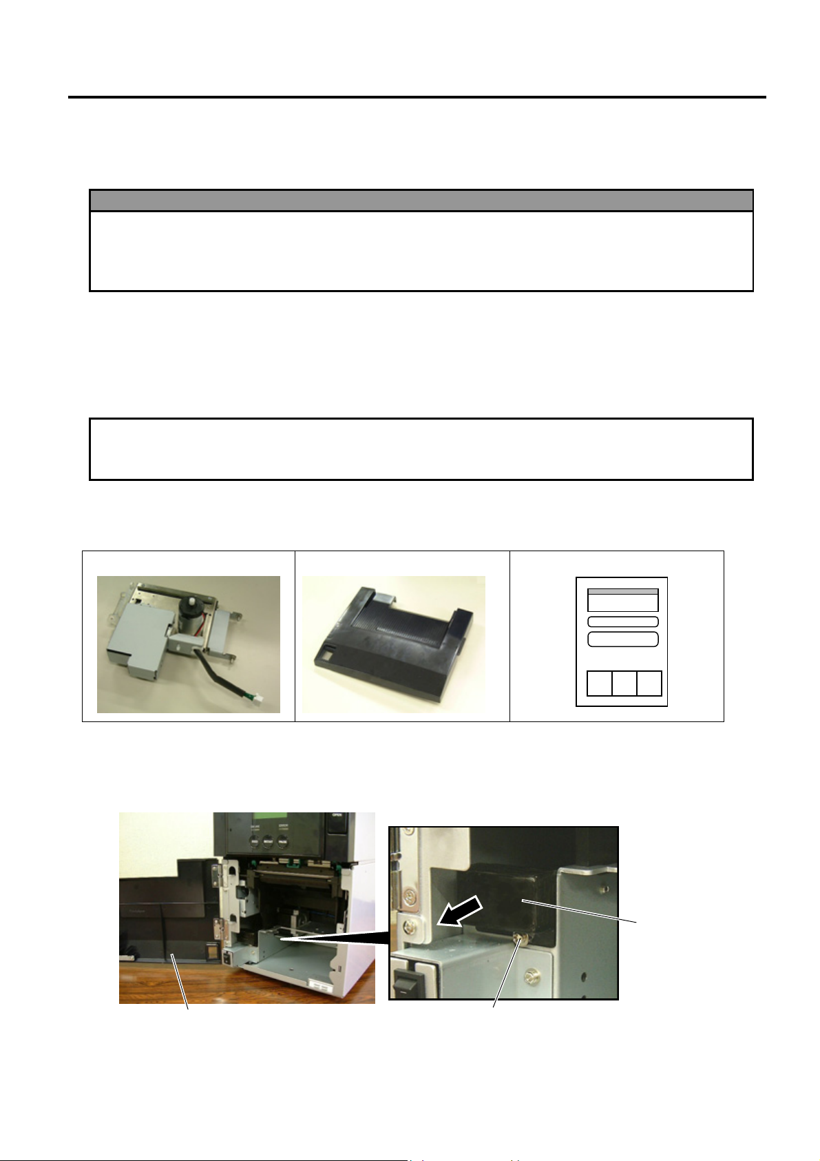
Packing List
•
The following parts are supplied with the kit. Make sure you have all items shown below.
rotect the internal electrical circuit of the printer.
to
Cutter Unit (1 pc.)
Cutter Module Cover (1 pc.)
Installation Manual (1 copy)
• Installation Procedure
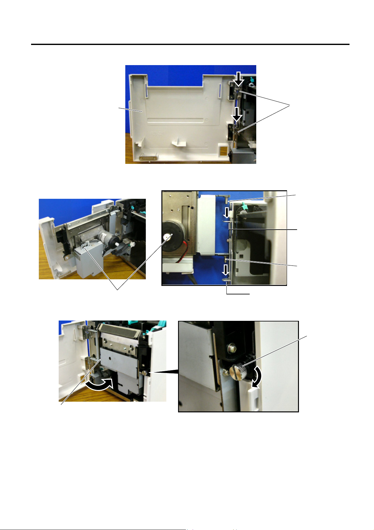
1. Open the Front Cover, and remove the B-3x6 screw to detach the Connector Cover.
Front Cove
B-3x6 Screw
Connector Cover
1- 1
Page 4
INSTALLATION PROCEDURE FOR OPTIONAL EQUIPMENT EO15-33001A
r
r
w
1. Cutter Module
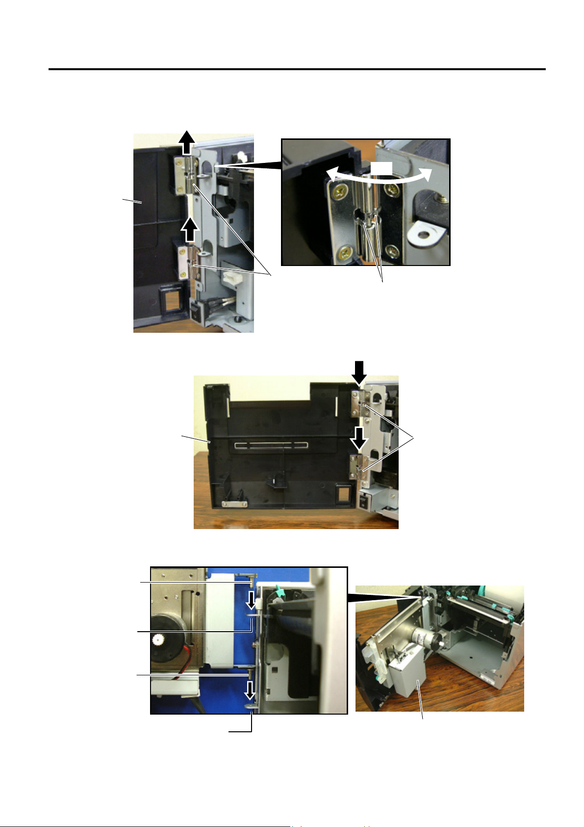
2. Open the Front Cover wider. Remove the Front Cove r by lifting it to disengage the hinge pins from the
hinge. The Front Cover cannot be removed unless it is opened at an angle of over 100 degrees a s the
stoppers of the hinge prevent disengagement.
100°
Front Cove
Hinge
Scre
3. Mount the Cutter Module Cover by inserting the hinge pins into the hinges.
Cutter Module Cove
Hinge
4. Fit the Cutter Unit to the front of the printer by inserting the Hinge Pins into the Hinge Pin Holes.
Hinge Pin
Hinge Pin Hole
Hinge Pin
Hinge Pin Hole
Cutter Unit
1- 2
Page 5
INSTALLATION PROCEDURE FOR OPTIONAL EQUIPMENT EO15-33001A
1. Cutter Module
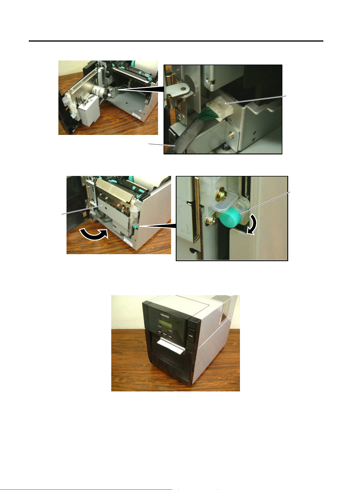
5. Connect the Cutter Harness to the connector at the front of the printer.
Connector
Cutter Harness
6. Close the Cutter Unit and secure it to the printer with the Set Screw.
Cutter Unit
7. Close the Cutter Module Cover.
Set Screw
• Media loading procedure------------- Owner’s Manual, Section 2.3
• Operation check------------------------ Owner’s Manual, Section 2.9
• System mode setting------------------System Mode Manual
• Cleaning --------------------------------- Owner’s Manual, Section 4.1.3
1- 3
Page 6
INSTALLATION PROCEDURE FOR OPTIONAL EQUIPMENT EO15-33001A
p
p
r
w
r
1. Cutter Module
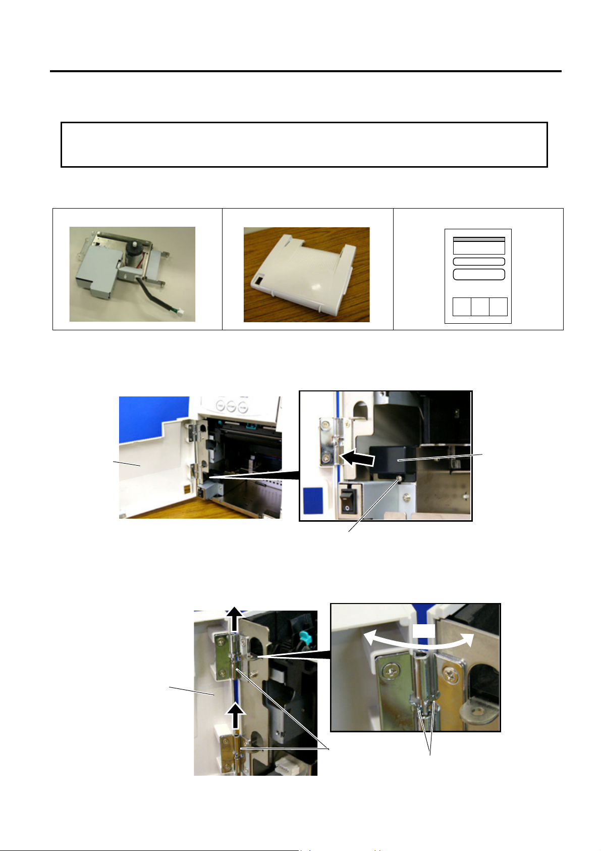
1.2 B-SA204P-QM-R
B-SA204P-QM-R is an optional cutter module for the B-SA4TP Series (Plastic cover).
CAUTION!
Do not connect/disconnect the cutter harness to/from the printer within one minute from a
rotect the internal electrical circuit of the printer.
to
ower off
• Packing List
The following parts are supplied with the kit. Make sure you have all items shown below.
Cutter Unit (1 pc.)
Cutter Module Cover (1 pc.)
Installation Manual (1 copy)
• Installation Procedure
1. Open the Front Cover, and remove the Connector Cover.
Front Cove
2. Open the Front Cover wider. Remove the Front Cove r by lifting it to disengage the hinge pins from the
hinge. The Front Cover cannot be removed unless it is opened at an angle of over 100 degrees a s the
stoppers of the hinge prevent disengagement.
Front Cove
B-3x6 Scre
100°
Hinge
Stopper
Connector Cover
1- 4
Page 7
INSTALLATION PROCEDURE FOR OPTIONAL EQUIPMENT EO15-33001A
r
1. Cutter Module
3. Mount the Cutter Module Cover by inserting the hinge pins into the hinges.
Cutter Module Cove
Hinge
4. Fit the Cutter Unit to the front of the printer by inserting the Hinge Pins into the Hinge Pin Holes.
Cutter Unit
5. Close the Cutter Unit and secure it to the printer with the Set Screw.
Cutter Unit
Hinge Pin
Hinge Pin Hole
Hinge Pin
Hinge Pin Hole
Set Screw
1- 5
Page 8
INSTALLATION PROCEDURE FOR OPTIONAL EQUIPMENT EO15-33001A
r
1. Cutter Module
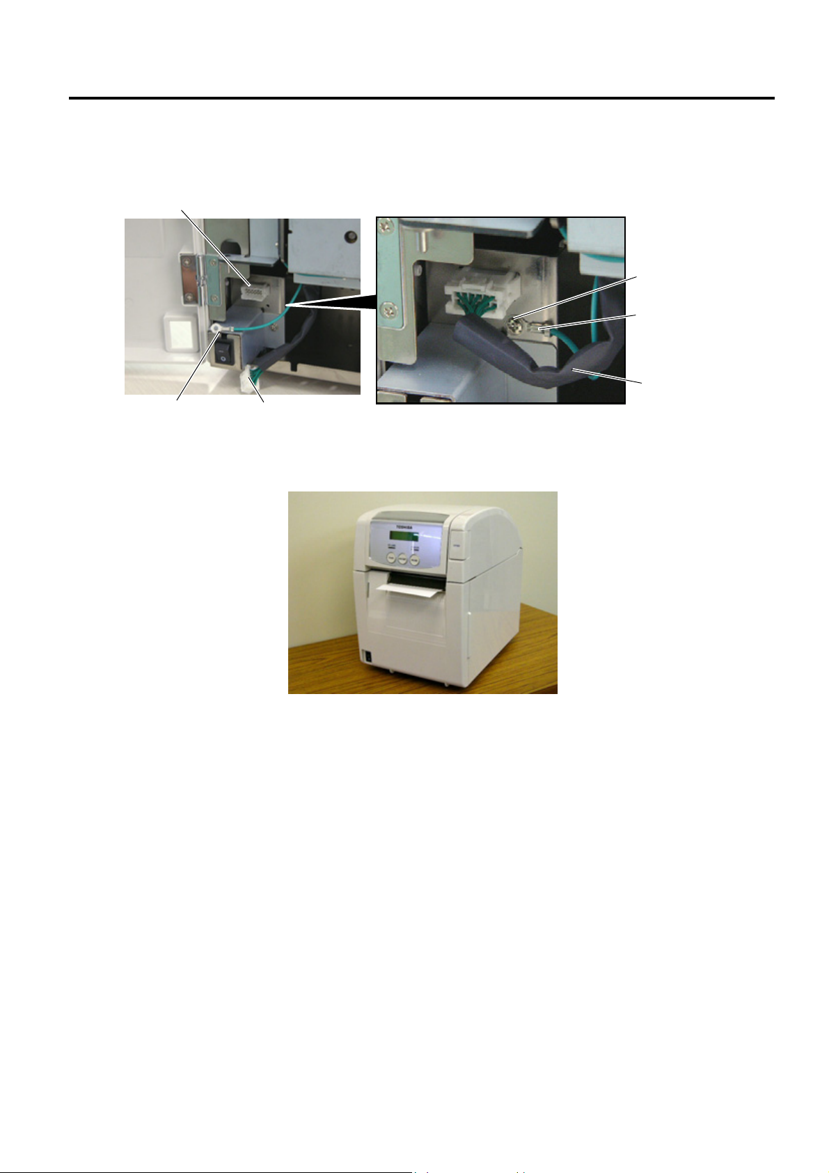
6. Secure the ground wire of the cutter unit to the printer with the B-3x6 screw removed in Step 1, as shown
in the picture.
7. Connect the cutter harness to the connector at the front of the printer.
Connecto
B-3x6 Screw
Ground Wire
Cutter Harness
Ground Wire
Cutter Harness
8. Close the Cutter Module Cover. After that, perform an operation check for a proper cut issue.
• Media loading procedure------------- Owner’s Manual, Section 2.3
• Operation check------------------------ Owner’s Manual, Section 2.9
• System mode setting------------------System Mode Manual
• Cleaning --------------------------------- Owner’s Manual, Section 4.1.3
1- 6
Page 9
INSTALLATION PROCEDURE FOR OPTIONAL EQUIPMENT EO15-33001A
r
w
(Revision Date: Jan. 19, 2006)
2. Strip Module
2. Strip Module
NOTE: Make sure that the firmware version is V1.1 or greater. Firmware V1.0 does not support the strip module.
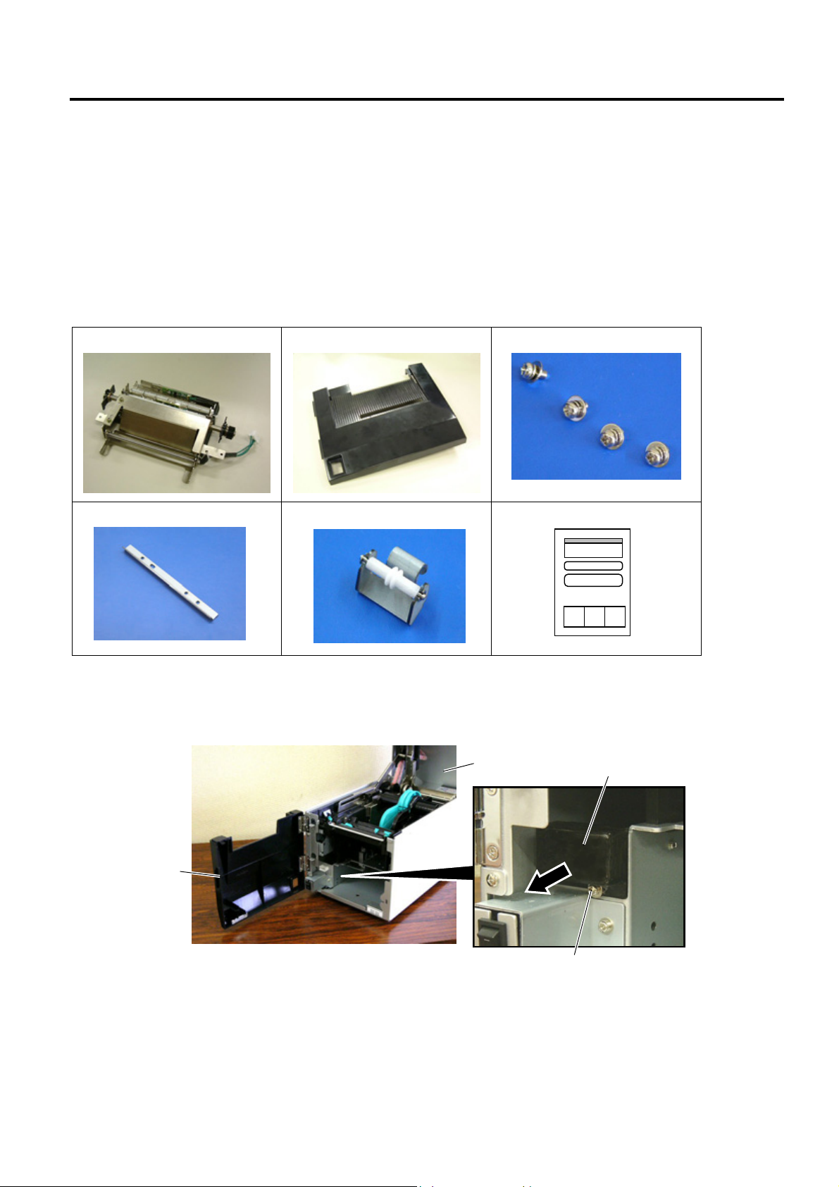
2.1 B-SA904-H-QM-R
B-SA904-H-QM-R is an optional strip module for the B-SA4TM Series (Metal cover).
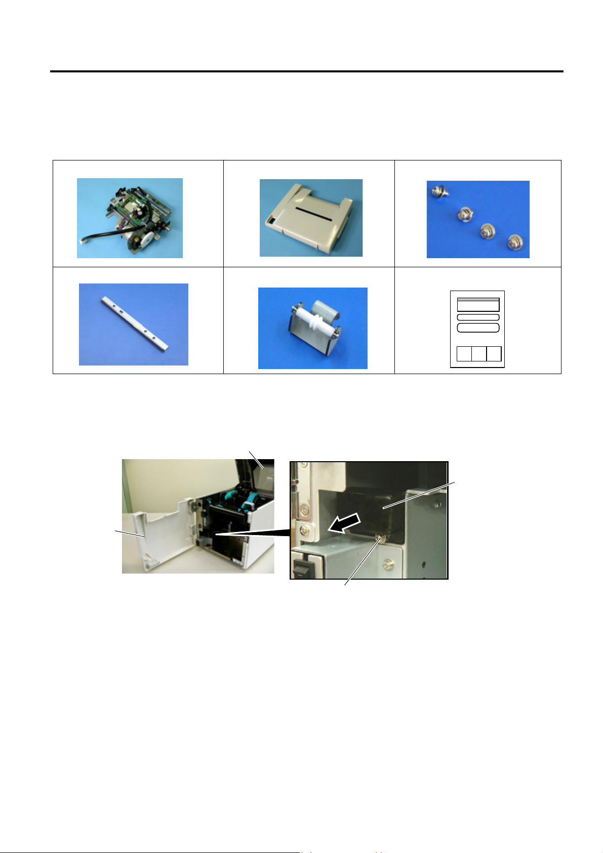
• Packing List
The following parts are supplied with the kit. Make sure you have all items shown below.
Strip Unit (1 pc.)
Strip Module Cover (1 pc.)
SMW-3x6 Screw (4 pc.)
Cutter (1 pc.)
NOTE: When issuing labels in batch mode even though the strip module is fitted, please use the provided cutter
to tear off the issued labels. Do not attach the cutter when labels are stripped one by one.
Guide Roller (1 pc.)
Installation Manual (1 copy)
• Installation Procedure
1. Open the Top Cover and the Front Cover. Remove the B-3x6 screw to detach the Connector Cover.
Top Cover
Connector Cover
Front Cove
B-3x6 Scre
2- 1
Page 10
INSTALLATION PROCEDURE FOR OPTIONAL EQUIPMENT EO15-33001A
r
r
w
2. Strip Module
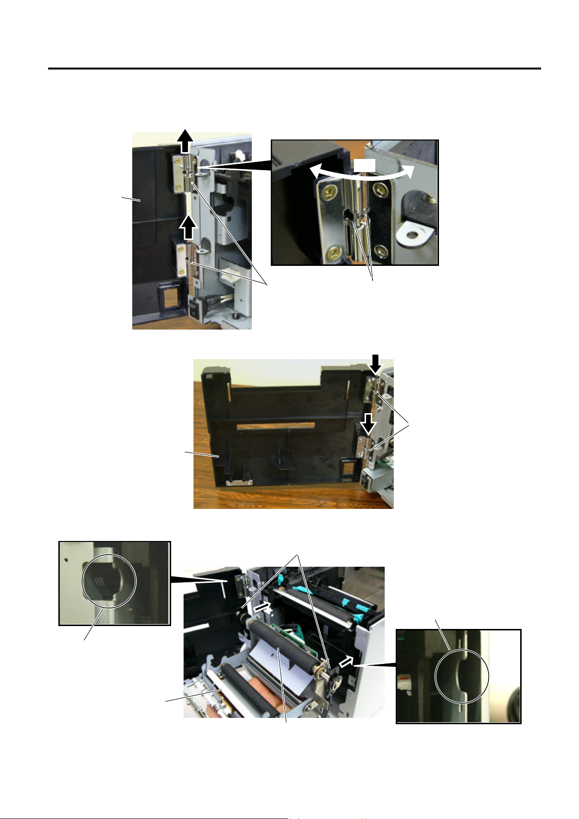
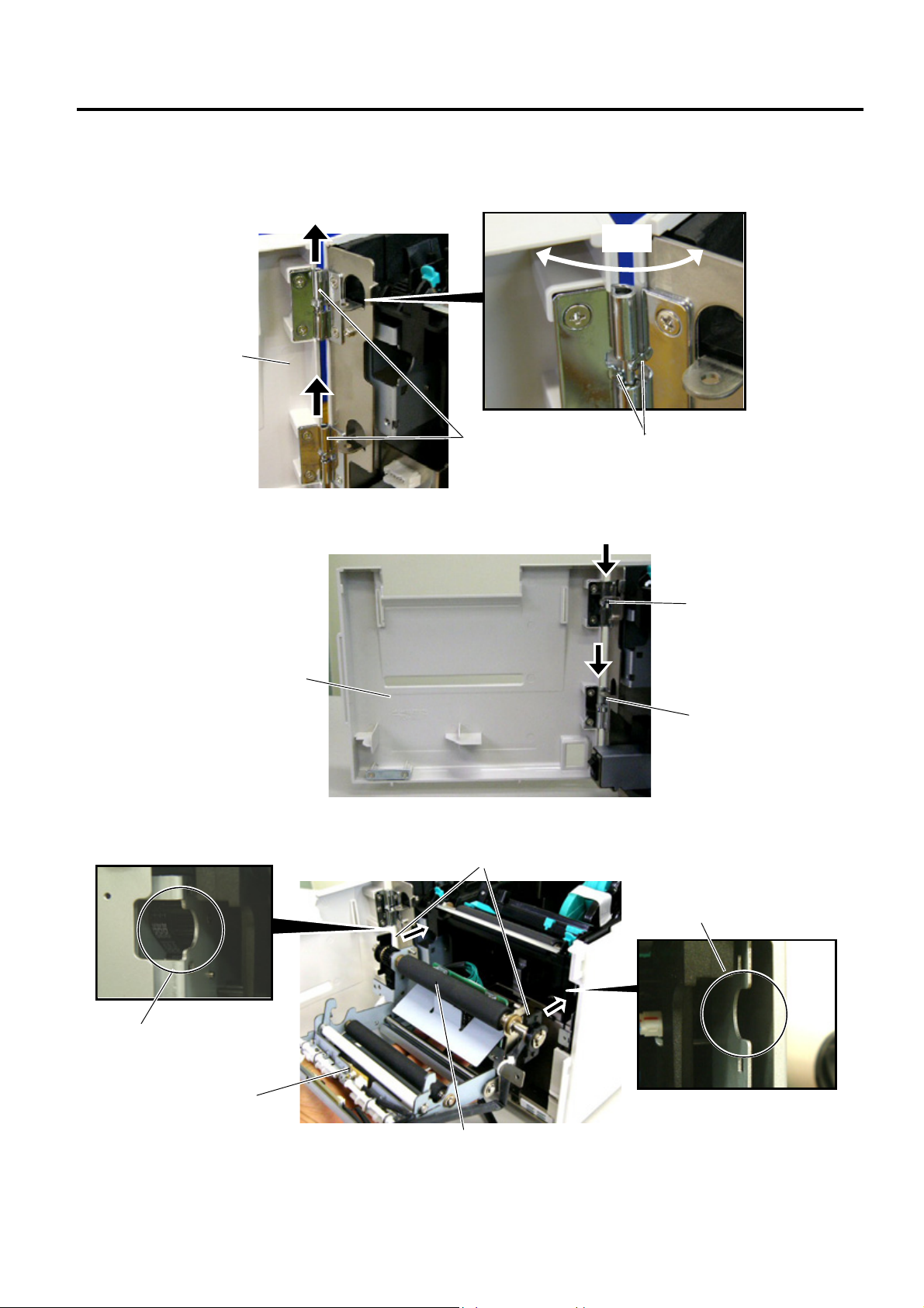
2. Open the Front Cover wider. Remove the Front Cove r by lifting it to disengage the hinge pins from the
hinge. The Front Cover cannot be removed unless it is opened at an angle of over 100 degrees a s the
stoppers of the hinge prevent disengagement.
100°
Front Cove
Hinge
Scre
3. Mount the Strip Module Cover by inserting the hinge pins into the hinges.
Hinge
Strip Module Cove
4. Fit the Shaft Holders of the Backing Paper Feed Roller into the cuts of the printer.
Shaft Holder
Cut
Cut
Strip Unit
Backing Paper Feed Roller
2- 2
Page 11
INSTALLATION PROCEDURE FOR OPTIONAL EQUIPMENT EO15-33001A
r
2. Strip Module
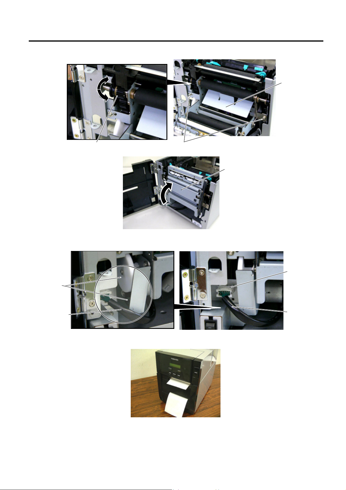
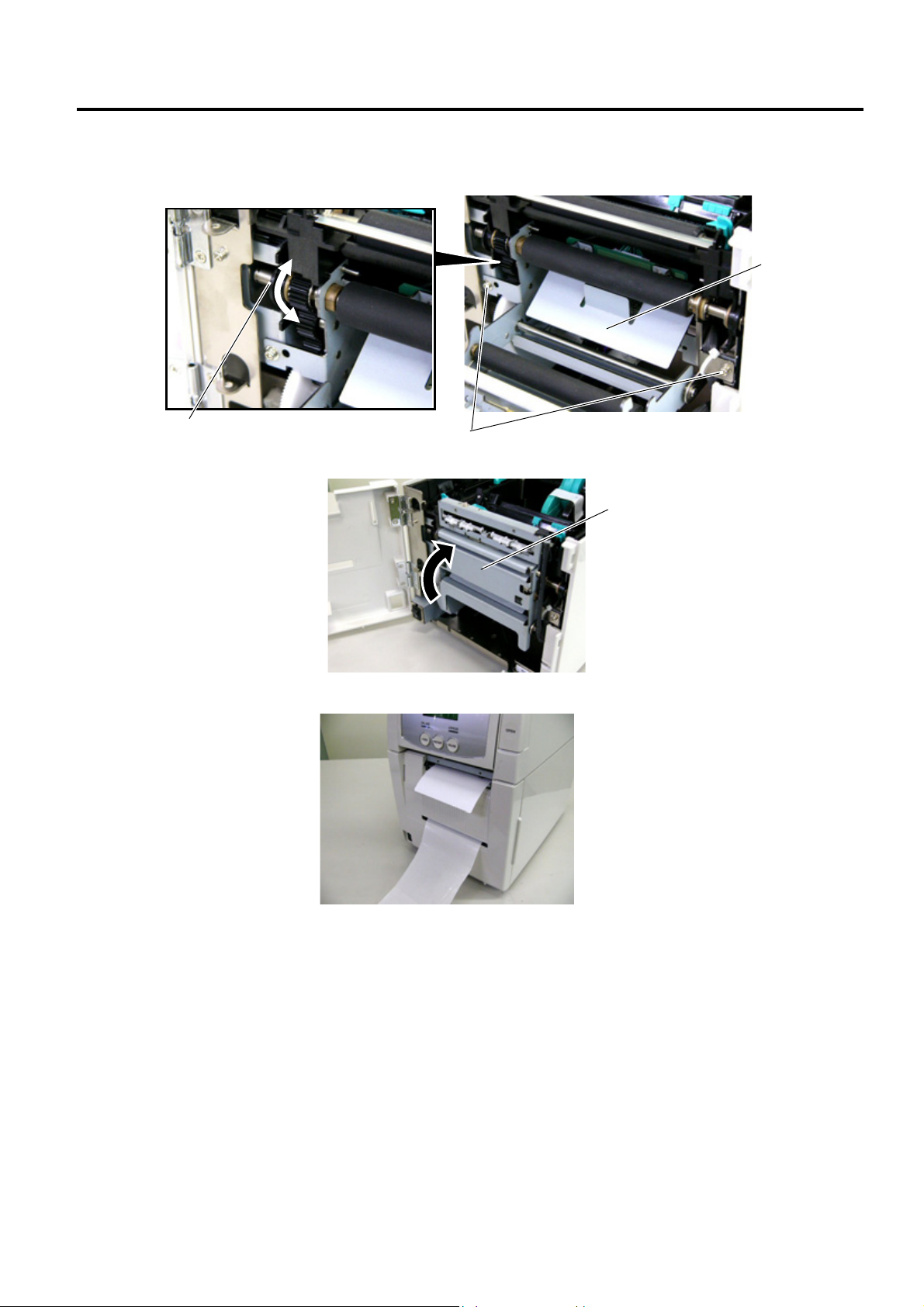
5. Secure the Strip Unit to the printer with the two screws. Make sure that the Feed Roller Gear rotates
smoothly.
Strip Unit
Feed Roller Gear
SMW-3x6 Screw
6. Close the Strip Unit.
Strip Unit
7. Connect the Strip Harness to the connector at the front of the printer. At this time, carefully avoid contact
of the strip harness with the gears.
Connector
Gea
Strip Harness
Strip Harness
8. Close the Strip Module Cover.
Perform an operation check for a proper strip issue.
• Media loading procedure------------- Owner’s Manual, Section 2.3
• Operation check------------------------ Owner’s Manual, Section 2.9
• System mode setting------------------System Mode Manual
• Cleaning --------------------------------- Owner’s Manual, Section 4.1.4
2- 3
Page 12
INSTALLATION PROCEDURE FOR OPTIONAL EQUIPMENT EO15-33001A
r
r
r
(Revision Date: Jan. 19, 2006)
2. Strip Module
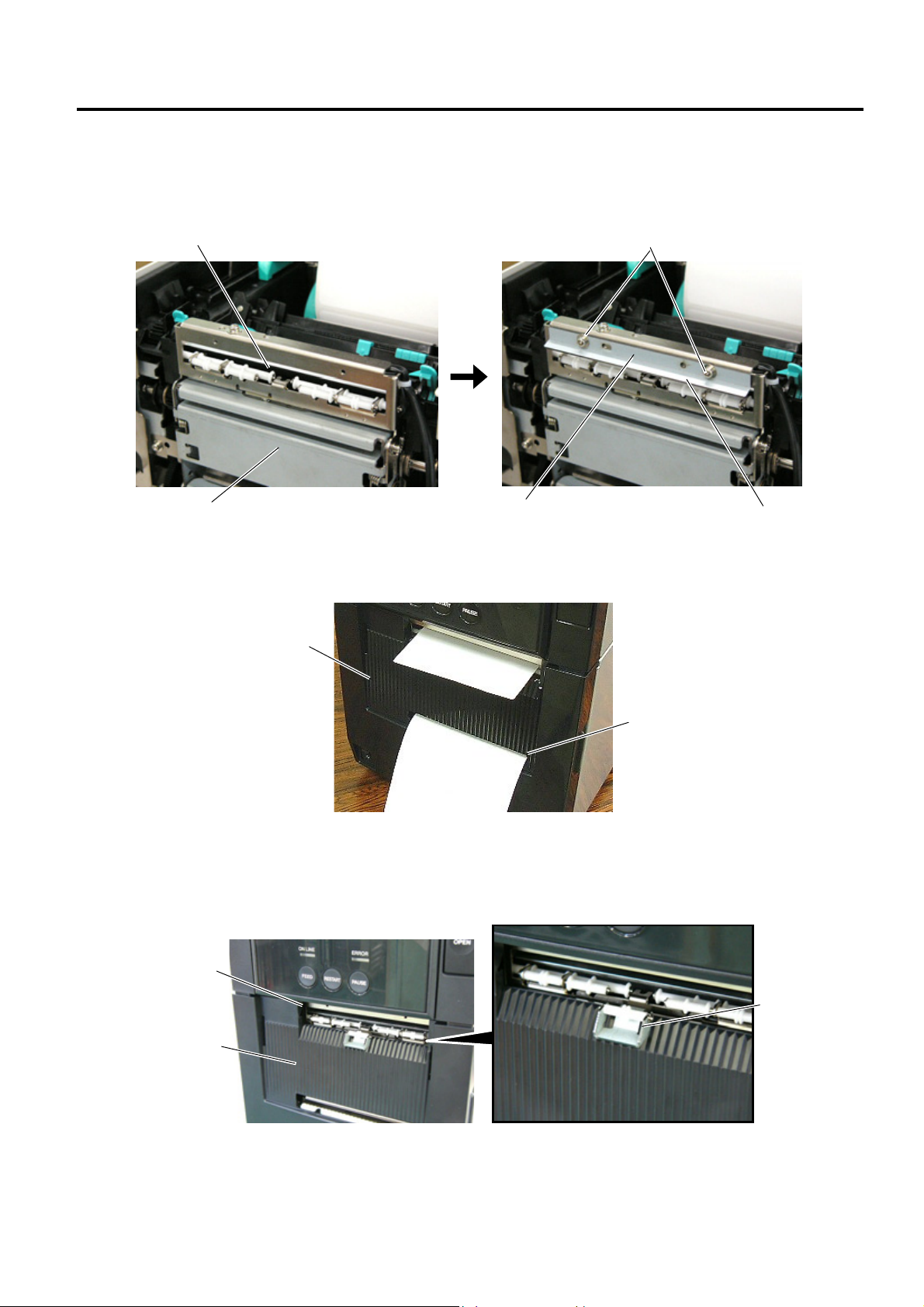
• Attaching the Cutter
The enclosed cutter is used to tear off the batch-issued labels. Attach the cutter with the two SMW-3x6
screws as shown in the picture below. Insert the leading edge of the labels into the opening under the
cutter.
Opening
SMW-3x6 Screw
NOTE: Depending on the backing paper types, tearing off the backing paper against the slot of the strip module
Strip Unit
cover may cause it to wind onto the inner rollers. It is advisable to tear off or cut the backing paper
outside the strip module cover.
Cutte
Edge
Strip Module Cove
Slot
• How to use the Guide Roller
When issuing the label with the length of 50 mm or more, fit the guide roller to the center of the strip module
cover to prevent the stripped label from sticking to the cover.
Strip Module Cove
Opening
Guide Roller
2- 4
Page 13
INSTALLATION PROCEDURE FOR OPTIONAL EQUIPMENT EO15-33001A
(Revision Date: Jan. 19, 2006)
2. Strip Module
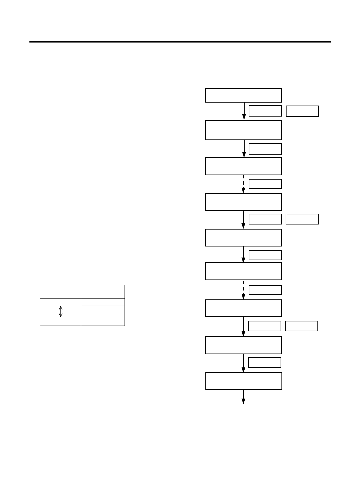
• System Mode Settings for Stripping PET Labels
When using PET labels on the strip module, please set the following system mode parameters in advance.
1. Connect the printer to a PC.
2. Load a PET label stock on the printer.
Turn the power ON.
3. Turn ON the printer while holding down the
[FEED] key and [PAUSE] key.
4. When “<1>DIAG. “ is displayed on the LCD,
press the [FEED] key to choose
<2>PARAMETER SET” menu.
5. Press the [PAUSE] key repeatedly until
“PRE PEEL OFF” appears on the LCD.
6. As the default is OFF, choose “PRE PEEL
OFF ON” with the [FEED] or [RESTART]
key. Then, press the [PAUSE] key.
7. “P.P. FEED +0.0mm” is displayed on the
LCD.
Press the [PAUSE] key repeatedly until
“PEEL OFF TRQ” appears on the LCD.
8. This menu is to set the strip motor torque.
As the default is R0, choose R3 with the
[FEED] or [RESTART] key. Then, press
the [PAUSE] key.
NOTE: Setting the motor torque higher
makes the strip issue easier.
FEED
<1>DIAG.
V1.1
FEED
<2>PARAMETER SET
PAUSE
<2>PARAMETER SET
PRE PEEL OFF OFF
<2>PARAMETER SET
PRE PEEL OFF ON
PAUSE
<2>PARAMETER SET
P.P.FEED +0.0mm
PAUSE
RESTARTFEED
Strip motor
torque
Low
High
Value
R0
R1
R2
R3
PAUSE
<2>PARAMETER SET
PEEL OFF TRQ R0
RESTARTFEED
<2>PARAMETER SET
PEEL OFF TRQ R3
PAUSE
<2>PARAMETER SET
(Continued.)
2- 5
Page 14
INSTALLATION PROCEDURE FOR OPTIONAL EQUIPMENT EO15-33001A
q
r
(Revision Date: Jan. 19, 2006)
2. Strip Module
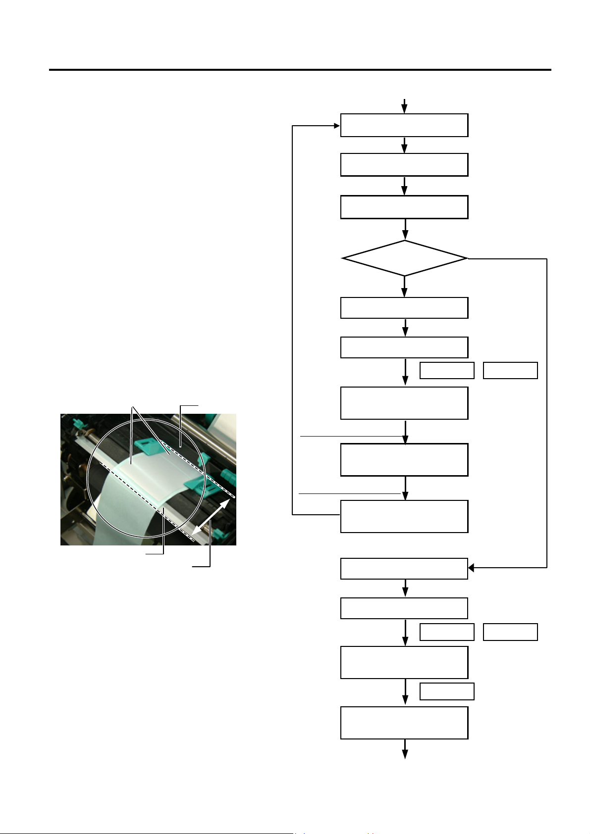
9. Turn off the printer, and then back to on.
Send an issue command to the printer for
strip issue.
10. If necessary, fine adjust the print start
position and strip position in the system
mode.
NOTES:
1. It is recommended that the print start
position and strip position are adjusted on
the actual print condition.
2. When short-pitch labels are used, the print
start position may misalign on the first few
labels. In that case, feed the labels
between the media sensor and the strip
shaft, and discard them.
Label
Media Senso
media sensor and the strip shaft.
Strip Shaft
Discard labels between the
11. Repeat Steps 9 and 10 for position fine
adjustment.
12. After the print position and strip position
are properly adjusted, access
“<2>PARAMETER SET” menu in the
system mode again.
(Continued.)
Turn the power OFF.
Turn the power ON.
Issue labels.
Print position
Adjustment
is re
uired.
Power OFF
Power ON
<1>DIAG.
V1.1
Print position fine adjustment
<3>ADJUST SET
FEED ADJ. +0.0mm
Strip position fine adjustment
<3>ADJUST SET
CUT ADJ. +0.0mm
Turn the power OFF.
Turn the power ON.
<1>DIAG.
V1.1
Good
FEED RESTART
FEED RESTART
FEED
<2>PARAMETER SET
Continued.
2- 6
Page 15
INSTALLATION PROCEDURE FOR OPTIONAL EQUIPMENT EO15-33001A
p
(Revision Date: Jan. 19, 2006)
2. Strip Module
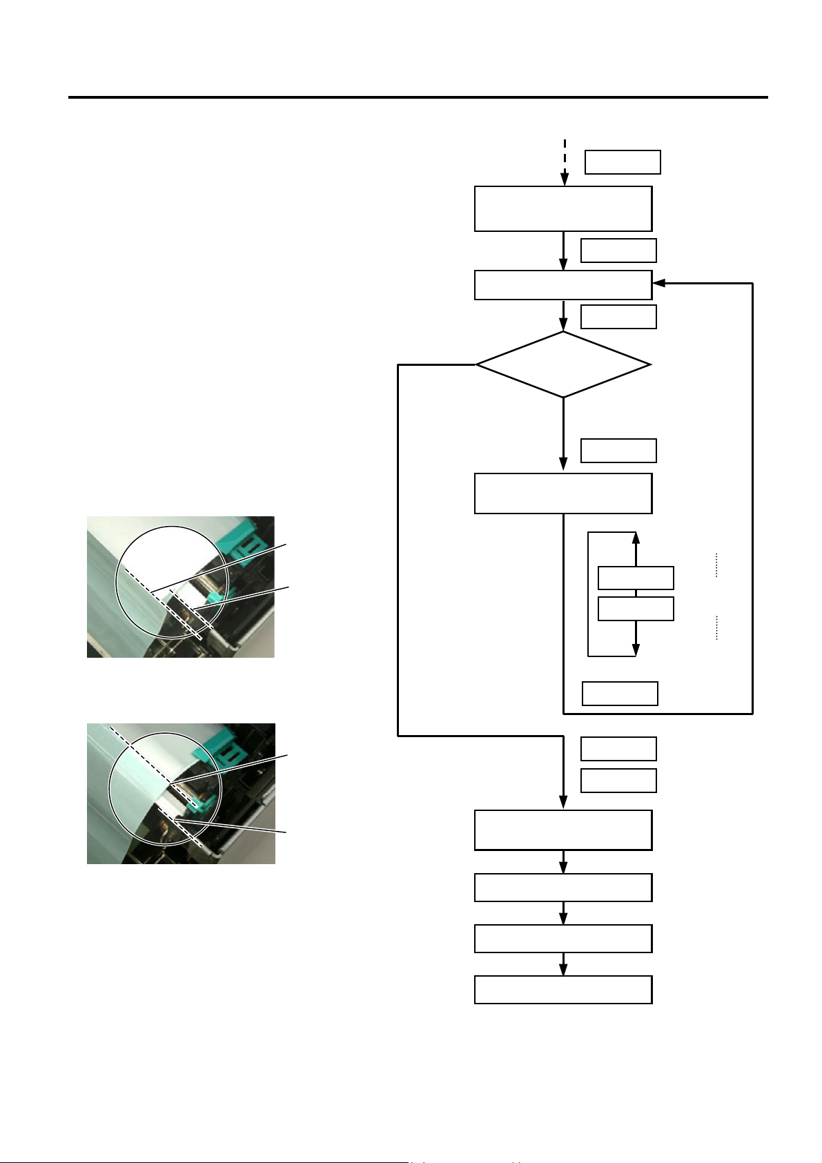
13. Press the [PAUSE] key repeatedly until
“P.P.FEED” appears on the LCD.
14. Press the [FEED] key to feed a label for
checking the next label’s stop position. If
the next label stops with its top edge
aligning with the strip shaft edge, an
adjustment is not required. Go to Step 15.
If not, press the [RESTART] key to return
to “P.P.FEED +0.0mm” display, and
adjust the pre-strip amount. Set the value
in a range from +9.9 to −2.5 with the
[FEED] or [RESTART] key.
When the top edge of the label stops past
the strip shaft edge, set a negative (−)
value.
Top edge of
the label
Strip Shaft Edge
When the top edge of the label stops short
of the strip shaft edge, set a positive (+)
value.
Top edge of
the label
Strip Shaft Edge
15. When the adjustment is completed, press
the [PAUSE] key twice to finish the setting.
<2>PARAMETER SET
P.P.FEED +0.0mm
The next label stops with its
top edge aligning with the
strip shaft edge.
<2>PARAMETER SET
P.P.FEED +0.0mm
<2>PARAMETER SET
BACK SPEED STD
Turn the power OFF.
Continued.
A label is fed.
Check the next
label’s stop
osition
The next label stops with its
top edge misaligning with the
strip shaft edge.
PAUSE
PAUSE
FEED
RESTART
RESTART
FEED
PAUSE
PAUSE
PAUSE
+9.9mm
+9.8mm
:
:
+0.1mm
+0.0mm
-0.1mm
:
:
-2.4mm
-2.5mm
16. Send an issue command to the printer
and check for proper strip issue.
Turn the power ON.
Label issue
2- 7
Page 16
INSTALLATION PROCEDURE FOR OPTIONAL EQUIPMENT EO15-33001A
r
r
w
(Revision Date: Jan: 19, 2006)
2. Strip Module
2.2 B-SA904P-H-QM-R
B-SA904P-H-QM-R is an optional strip module for the B-SA4TP Series (Plastic cover).
• Packing List
Strip Unit (1 pc.)
Cutter (1 pc.)
Strip Module Cover (1 pc.)
Guide Roller (1 pc.)
SMW-3x6 Screw (4 pcs.)
Installation Manual (1 copy)
NOTE: When issuing labels in batch mode even though the strip module is fitted, please use the provided
cutter to tear off the issued labels. Do not attach the cutter when labels are stripped one by one.
• Installation Procedure
1. Open the Top Cover and the Front Cover. Remove the Connector Cover.
Front Cove
Top Cove
Connector Cover
B-3x6 Scre
2- 8
Page 17
INSTALLATION PROCEDURE FOR OPTIONAL EQUIPMENT EO15-33001A
r
r
t
2. Strip Module
2. Open the Front Cover wider. Remove the Front Cover by lifting it to disengage the hi nge pins from the
hinge. The Front Cover cannot be removed unless it is opened at an angle of over 100 deg rees as the
stoppers of the hinge prevent disengagement.
100°
Front Cove
Hinge
Stopper
3. Mount the strip Module Cover by inserting the hinge pins into the hinges.
Hinge
Strip Module Cove
Hinge
4. Fit the Shaft Holders of the Backing Paper Feed Roller into the cuts of the printer.
Shaft Holder
Cut
Cut
Strip Uni
Backing Paper Feed Roller
2- 9
Page 18
INSTALLATION PROCEDURE FOR OPTIONAL EQUIPMENT EO15-33001A
2. Strip Module
5. Secure the Strip Unit to the printer with the two screws. Make sure that the Feed Roller Gear rotates
smoothly.
Strip Unit
Feed Roller Gear
SMW-3x6 Screw
6. Close the Strip Unit.
Strip Unit
7. Close the Strip Module Cover. Perform an operation check for a proper strip issue.
• Media loading procedure------------- Owner’s Manual, Section 2.3
• Operation check------------------------ Owner’s Manual, Section 2.9
• System mode setting------------------System Mode Manual
• Cleaning --------------------------------- Owner’s Manual, Section 4.1.4
2- 10
Page 19

INSTALLATION PROCEDURE FOR OPTIONAL EQUIPMENT EO15-33001A
r
r
(Revision Date: Jan. 19, 2006)
2. Strip Module
• Attaching the Cutter
The enclosed cutter is used to tear off the batch-issued labels. Attach the cutter with the two SMW-3x6
screws as shown in the picture below. Insert the leading edge of the labels into the opening under the
cutter.
Opening
SMW-3x6 Screw
Strip Unit
Cutte
Edge
NOTE: Depending on the backing paper types, tearing off the backing paper against the slot of the strip
module cover may cause it to wind onto the inner rollers. It is advisable to tear off or cut the
backing paper outside the strip module cover.
Slot
• How to use the Guide Roller
When issuing the label with the length of 50 mm or more, fit the guide roller to the center of the strip module
cover to prevent the stripped label from sticking to the cover.
Strip Module Cove
NOTE: Regarding the system mode setting for use of PET paper, refer to Section 2.1.
Opening
Guide Roller
2- 11
Page 20

INSTALLATION PROCEDURE FOR OPTIONAL EQUIPMENT EO15-33001A
(Revision Date: Jan. 19, 2006)
3. Wireless LAN Module: B-SA704-WLAN-QM
3. Wireless LAN Module: B-SA704-WLAN-QM
The pictures used in this section are those of the B-SA4TM, and the installation procedures are common
with the B-SA4TP unless otherwise noted.
• Packing List
The following parts are supplied with the kit. Make sure you have all items shown below.
Wireless LAN Board (1 pc.)
Installation Manual (1 copy)
NOTES:
1. DO NOT CHANGE the DIP Switch settings on the Wireless LAN Board. Doing so may cause a malfunction.
2. MAC address of the Wireless LAN module will be necessary when setting the MAC address filtering function
of an access point. As it is printed on the top of the wired LAN connector on the Wireless LAN Board, write
down it on Installation Manual before mounting the covers so that an end user can know the MAC address.
3. Be careful not to hit or damage the antenna when installing this kit. A damaged antenna may affect the
performance.
Antenna Cover (1 pc.)
Shield Sheet (1.pc)
SMW-3x6 Screw (4 pcs.)
FCC/IC Sticker (1 pc.)
MAC Address
12-digit code printed on the right
side of “W” is MAC address.
Antenna
Wireless LAN Board
4. The shield sheet is used only when this option is installed in the B-SA4TP model.
DIP Switch
3- 1
Page 21

INSTALLATION PROCEDURE FOR OPTIONAL EQUIPMENT EO15-33001A
r
r
w
w
r
k
3. Wireless LAN Module: B-SA704-WLAN-QM
• Installation Procedure
1. Remove the two SMW-3x6 screws from the back of the printer.
SMW-3x6
Side Panel
2. Remove the Side Panel in the following order. Please note the procedure is different between the B-
SA4TM series and the B-SA4TP series.
B-SA4TM B-SA4TP
(1).Open the Top Cover and Front Cover.
Top Cove
Front Cove
(2). Remove the two SMW-3x6 screws which secure
the Side Panel.
SMW-3x6 Scre
Side Panel
SMW-3x6 Scre
(3). Close the Front Cover and remove the Side Panel.
Side Panel
Open the Top Cover. Slide the Side Panel backward,
and then remove it in the direction of arrow A.
Top Cove
Side Panel
A
Reverse side of Side Panel
Hoo
3- 2
Page 22

INSTALLATION PROCEDURE FOR OPTIONAL EQUIPMENT EO15-33001A
w
A
(Revision Date: Jan. 19, 2006)
3. Wireless LAN Module: B-SA704-WLAN-QM
3. Remove the two SMW-3x6 screws to detach the Blind Plate.
Blind Plate
SMW-3x6
4. Remove the SMW-3x8 screw to detach the Cable Clamp.
Cable Clamp
SMW-3x8 Scre
5. Put the Antenna of the Wireless LAN Board out of the opening in the printer back.
Care must be taken not to hit the Antenna against the printer frame, as damaged antenna may affect the
performance.
Antenna
Opening
Wireless LAN Board
ntenna
3- 3
Page 23

INSTALLATION PROCEDURE FOR OPTIONAL EQUIPMENT EO15-33001A
w
(Revision Date: Jan. 19, 2006)
3. Wireless LAN Module: B-SA704-WLAN-QM
6. As the following picture shows, secure the Wireless LAN Board to the printer back with two of the
enclosed SMW-3x6 screws. Also, secure the Wireless LAN Board to the PCB Support Plate with the
SMW-3x8 screw together with the Cable Clamp removed in Step 4.
Copper foil
Print Head Cable
PCB Support Plate
Cable Clamp
SMW-3x8 Scre
SMW-3x6 Screw
Wireless LAN Board
7. Only when this option is installed in the B-SA4TP printer, remove the three backing papers from the
shield sheet and attach the shield sheet so that it covers the wireless LAN module.
Shield Sheet
Backing Paper
Glue
Shield Sheet
Wireless LAN Module
Glue
3- 4
Page 24

INSTALLATION PROCEDURE FOR OPTIONAL EQUIPMENT EO15-33001A
A
3. Wireless LAN Module: B-SA704-WLAN-QM
8. Connect the Wireless LAN Power Cable and the LAN Cable as shown below.
CN12
CN17
LAN Cable
Wireless LAN Power Cable
9. Fit the Antenna Cover to the back of the printer. Secure it with the SMW-3x6 screw.
SMW-3x6 Screw
10. Re-attach the Side Panel to the printer.
ntenna Cover
Pass the LAN Cable through the
cut of the Antenna Cover.
LAN Cable
3- 5
Page 25

INSTALLATION PROCEDURE FOR OPTIONAL EQUIPMENT EO15-33001A
3. Wireless LAN Module: B-SA704-WLAN-QM
• Country Code
As available frequency bands are different from country to country, be sure to set a country code before
installing a wireless LAN module in a user’s printer. Also, ask an end user to confirm a country code. Use
of a wireless LAN module with a wrong country code could violate each country’s Laws and Regulations for
Radio Equipment, and violators could be subject to penalties.
The country code cannot be changed through the Web browser, but TELNET.
<How to set a country code using TELNET>
CAUTION! The following information must not be disclosed to users. (Internal use only)
(1) Disconnect the LAN cable connected to the printer, connect the printer to a host PC with a straight
LAN cable via a relay connector.
When using a hub in place of a relay connector, use a cross cable or
(2) Open the MS-DOS prompt, type in “telnet 192.168.10.21” (default IP address).
(3) Enter a password to log in. (Password: tecbcp)
(4) From the top menu, change a country code using the following command.
=>ctry XX (XX=new country code. See Country Code Table.)
(5) The new country code will become effective by turning the printer off and on again.
(6) A country code can be checked by typing “=>ctry” on the telnet console.
<Country Code Table>
Country
code
US U.S.A./Canada GR Greece IE Ireland
FR France SE Sweden GB U.K.
PT Portugal HU Hungary AU Australia
NO Norway BE Belgium FI Finland
DE Germany IT Italy LU Luxembourg
ES Spain NL Netherlands CH Switzerland
IS Iceland LI Liechtenstein NZ New Zealand
AT Austria DK Denmark
Country name
Country
code
Country name
Country
code
Country name
Regarding various settings or operation check for the wireless LAN, refer to the System Mode Manual.
3- 6
Page 26

INSTALLATION PROCEDURE FOR OPTIONAL EQUIPMENT EO15-33001A
4. Serial Interface Board: B-SA704-RS-QM-R
4. Serial Interface Board: B-SA704-RS-QM-R
The pictures used in this section are those of the B-SA4TM, and the installation procedures are common
with the B-SA4TP unless otherwise noted.
• Packing List
The following parts are supplied with the kit. Make sure you have all items shown below.
SIO PC Board (1 pc.)
Serial Interface Cable
SMW-3x6 Screw (3 pcs.)
Locking Support (1 pc.)
Installation Manual (1 copy)
PCB Support Plate (1 pc.)
NOTE: Make sure that the Serial Interface Cable is connected to CN4 on the SIO PC Board.
• Installation Procedure
1. Remove the two screws from the back of the printer.
SMW-3x6
Side Panel
4- 1
Page 27

INSTALLATION PROCEDURE FOR OPTIONAL EQUIPMENT EO15-33001A
r
r
w
w
r
k
4. Serial Interface Board: B-SA704-RS-QM-R
2. Remove the Side Panel in the following order. Please note the procedure is different between the BSA4TM series and the B-SA4TP series.
B-SA4TM B-SA4TP
(1).Open the Top Cover and Front Cover.
Top Cove
Front Cove
(2). Remove the two SMW-3x6 screws which secure
the Side Panel.
SMW-3x6 Scre
Side Panel
SMW-3x6 Scre
(3). Close the Front Cover and remove the Side Panel.
Side Panel
Open the Top Cover. Slide the Side Panel backward,
and then remove it in the direction of arrow A.
Top Cove
Side Panel
A
Reverse side of Side Panel
Hoo
3. Remove the two screws to detach the Blind Plate.
Blind Plate
SMW-3x6
4- 2
Page 28

INSTALLATION PROCEDURE FOR OPTIONAL EQUIPMENT EO15-33001A
4. Serial Interface Board: B-SA704-RS-QM-R
4. Attach the enclosed PCB Support Plate to the printer back with one of the enclosed SMW-3x6 screws.
SMW-3x6
PCB Support Plate
5. Fit the Locking Support into the MAIN PC Board.
MAIN PC Board
Locking Support
6. Connect the Serial Interface Cable of the SIO PC Board to CN12 on the MAIN PC Board.
MAIN PC Board
CN12
SIO PC Board
Serial Interface Cable
4- 3
Page 29

INSTALLATION PROCEDURE FOR OPTIONAL EQUIPMENT EO15-33001A
4. Serial Interface Board: B-SA704-RS-QM-R
7. Secure the SIO PC Board to the printer back with the two SMW-3x6 screws. Fit the Locking Support into
the SIO PC Board.
SMW-3x6
SIO PC Board
Locking Support
8. Re-attach the Side Panel.
9. For an operation check, settings, etc., refer to the.
4- 4
Page 30

INSTALLATION PROCEDURE FOR OPTIONAL EQUIPMENT EO15-33001A
!
5. 300 dpi Print Head Kit: B-SA704-TPH3-QM-R
5. 300 dpi Print Head Kit: B-SA704-TPH3-QM-R
B-SA704-TPH3-QM-R is an optional 300 dpi print head kit for the B-SA4TM/SA4TP-GS12 Series (203dpi
printer).
You will obtain the same print quality as the TS12 model (300 dpi) only by replacing the current print head
with this optional kit.
The pictures used in this section are those of the B-SA4TM, however, the installation procedure is common
with the B-SA4TP.
Do not touch the print head or its neighboring parts immediately after printing, or you may burn
yourself.
CAUTION!
1. NEVER loosen or remove the following two screws of the Print Head as they have been fine
adjusted before shipment. If they are loosened or removed, print quality may become
deteriorated.
2. Do not touch the Print Head Element when handling the Print Head.
NEVER loosen or remove
these screws.
WARNING
• Packing List
The following parts are supplied with the kit. Make sure you have all items shown below.
300 dpi print head (1 pc.)
Installation Manual (1 copy)
5- 1
Page 31

INSTALLATION PROCEDURE FOR OPTIONAL EQUIPMENT EO15-33001A
r
7. Expansion IO Board: B-SA704-IO-QM-R
• Installation Procedure
1. Fully open the Ribbon Cover.
2. Slightly open the Top Cover (10 mm).
3. Unlock the Print Head by pressing the hooks toward the center. Then pull the Print Head downward.
NOTE: Care must be taken not to damage the Print Head Element by hitting it against any metal parts.
4. Disconnect the Print Head Cable from the Print Head.
5. Replace the Print Head with a new one, and then reassemble in the reverse order of removal.
Ribbon Cove
Top Cover
Hook
Print Head
Print Head Cable
Print Head (B-SA704-TPH3-QM-R)
5- 2
Page 32

INSTALLATION PROCEDURE FOR OPTIONAL EQUIPMENT EO15-33001A
w
(Revision Date: Jan. 19, 2006)
6. Real Time Clock: B-SA704-RTC-QM-R
6. Real Time Clock: B-SA704-RTC-QM-R
B-SA704-RTC-QM-R is an optional Real Time Clock for the B-SA4TM/SA4TP Series. The pictures used in
this section are those of the B-SA4TP, and the installation procedures are common with the B-SA4TM
unless otherwise noted.
NOTE: When the B-SA704-IO-QM-R Expansion I/O Board or B-SA704-RS-QM-R Serial Interface Board
has been already installed in the printer, the Interface Cable of the Real Time Clock cannot be
connected to the MAIN PC Board. Please remove this optional PC board temporality, prior to
installing the Real Time Clock.
• Packing List
The following parts are supplied with the kit. Make sure you have all items shown below.
Real Time Clock (1 pc.) See Note.
Interface
Cable
Installation Manual (1 copy)
SMW-4x8 Screw (1 pc.)
Battery Sticker (1 pc.)
Lithium Battery CR2032 (1 pc.)
Note: Make sure that the
Interface Cable is
connected to CN1 on the
Real Time Clock.
• Installation Procedure
1. Remove the two SMW-3x6 screws from the back of the printer.
SMW-3x6 Scre
Side Panel
6- 1
Page 33

INSTALLATION PROCEDURE FOR OPTIONAL EQUIPMENT EO15-33001A
r
r
w
w
r
k
(Revision Date: Jan. 19, 2006)
6. Real Time Clock: B-SA704-RTC-QM-R
2. Remove the Side Panel in the following order. Please note the procedure is different between the BSA4TM series and the B-SA4TP series.
B-SA4TM B-SA4TP
(1).Open the Top Cover and Front Cover.
Top Cove
Front Cove
(2). Remove the two SMW-3x6 screws which secure
the Side Panel.
SMW-3x6 Scre
Side Panel
SMW-3x6 Scre
(3). Close the Front Cover and remove the Side Panel.
Side Panel
Open the Top Cover. Slide the Side Panel backward,
and then remove it in the direction of arrow A.
Top Cove
Side Panel
A
Reverse side of Side Panel
Hoo
3. Place the Lithium Battery into the Battery Socket in the direction of the arrow.
Lithium Battery
Battery Socket
+
6- 2
Page 34

INSTALLATION PROCEDURE FOR OPTIONAL EQUIPMENT EO15-33001A
w
(Revision Date: Jan. 19, 2006)
6. Real Time Clock: B-SA704-RTC-QM-R
NOTES: 1. Place the battery with the “+” mark facing up.
2. A new battery is supposed to last about 2 years or more, but it varies depending on the
operating conditions. When a new battery is loaded, write down the battery replacement date
on a supplied battery sticker, and attach it to the reverse side of the Side Panel as a reminder.
Battery Sticker
Reverse side of Side Panel
4. Attach the Real Time Clock to the printer with the SMW-4x8 screw.
Real Time Clock
SMW-4x8 Scre
6- 3
Page 35

INSTALLATION PROCEDURE FOR OPTIONAL EQUIPMENT EO15-33001A
(Revision Date: Jan. 19, 2006)
6. Real Time Clock: B-SA704-RTC-QM-R
5. Pass the Interface Cable through the Cable Clamp, and between CN1 and CN2 on the MAIN PC
Board, as shown in the pictures below. For the B-SA4TP model, wind the cable on the two Cable
Clamps.
B-SA4TP Model
Connector CN2
MAIN PC Board
Interface Cable
B-SA4TM Model
Connector CN1
Connector CN2
Cable Clamp
Interface Cable
MAIN PC Board
Interface Cable
Connector CN1
Cable Clamp
Interface Cable
6. Connect the Interface Cable to CN501 on the MAIN PC Board.
CN501
MAIN PC Board
Interface Cable
7. Attach the Side Panel, removed in Step 2, back to the printer. Care must be taken not to catch the
Interface Cable by the Side Panel.
NOTE: When the B-SA704-IO-QM-R Expansion I/O Board or B-SA704-RS-QM-R Serial Interface Board was
removed beforehand, re-install it.
6- 4
Page 36

INSTALLATION PROCEDURE FOR OPTIONAL EQUIPMENT EO15-33001A
r
/
(Revision Date: Jan. 19, 2006)
6. Real Time Clock: B-SA704-RTC-QM-R
• System Setting (Date and Time Setting)
Set the date and time using the following procedure.
NOTE: Make sure that the printer version is V1.2 or greater. The real time clock is not supported by V1.1
or older.
1. Turn on the printer. “ONLINE” will be
displayed on the LCD.
2. Press the [PAUSE] key to turn the printer to
pause state.
ONLINE
B-SA4T V1.2
Power ON
PAUSE
3. Hold down the [RESTART] key until the
printer enters the system mode.
NOTE: For details of the system mode, refer to the
B-SA4T Series Owner’s Manual stored in
the CD-ROM supplied with the printer.
4. When “<1>RESET” is displayed on the LCD,
press the [RESTART] key until “<8>RTC SET”
appears.
5. Press the [PAUSE] key. The date currently
stored in the real time clock is displayed.
6. Pressing the [PAUSE] key enables changing
the Year.
7. Set the Year with the [FEED] or [RESTART]
key. Pressing the [PAUSE] key fixes the Year
and causes the cursor to move to the Month.
8. Set the Month with the [FEED] or [RESTART]
key. Pressing the [PAUSE] key fixes the
Month and causes the cursor to move to the
Day.
9. Set the Day with the [FEED] or [RESTART]
key. Press the [PAUSE] key to fix the Day.
Then, the time currently stored in the real time
clock is displayed.
PAUSE
B-SA4T V1.2
<1>RESET
<8>RTC SET
<8>RTC SET
DATE 05/01/01
<8>RTC SET
DATE Y 05
Yea
<8>RTC SET
DATE M 06/01
<8>RTC SET
DATE D 06/03/01
<8>RTC SET
TIME 00/00/00
/01/01
(Continued.)
RESTART
RESTART
PAUSE
PAUSE
PAUSE
01
PAUSE
PAUSE
FEED RESTART
Month
FEED RESTART
Day
FEED RESTART
6- 5
Page 37

INSTALLATION PROCEDURE FOR OPTIONAL EQUIPMENT EO15-33001A
r
(Revision Date: Jan. 19, 2006)
6. Real Time Clock: B-SA704-RTC-QM-R
10. Pressing the [PAUSE] key enables setting the
Hour.
11. Set the Hour with the [FEED] or [RESTART]
key. Pressing the [PAUSE] key fixes the Hour
and cause the cursor to move to the Minute.
12. Set the Minute with the [FEED] or [RESTART]
key. Pressing the [PAUSE] key fixes the
Minute and cause the cursor to move to the
Second.
13. Set the second with the [FEED] or [RESTART]
key. Press the [PAUSE] key to fix the Second.
Then, the Low Battery Check selection screen
is displayed.
14. Pressing the [PAUSE] key enables choosing
whether to activate the low battery check
function or not. Set the function to ON or OFF
with the [FEED] or [RESTART] key.
ON: Low battery check function is activated.
OFF: Low battery check function is not
activated. (Default)
Press the [PAUSE] key to fix the setting. Then,
the RTC Data Renewal Timing setting screen is
displayed.
(Continued from the
previous page)
<8>RTC SET
TIME H 00
Hou
<8>RTC SET
TIME M 10/00
<8>RTC SET
TIME S 10/30/00
<8>RTC SET
LOW BATT. CHECK
<8>RTC SET
LOW BATT. OFF
/00/00
/00
PAUSE
FEED RESTART
PAUSE
Minute
FEED RESTART
PAUSE
Second
FEED RESTART
PAUSE
PAUSE
FEED RESTART
15. Pressing the [PAUSE] key enables choosing
PAUSE
the RTC data renewal timing.
16. Choose PAGE or BATCH with the [FEED] or
[RESTART] key.
PAGE: A real time can be printed on each
<8>RTC SET
RENEWAL
PAUSE
media. However, the printer needs to
stop the motion before printing each
media to read the real time clock data.
BATCH: Batch print is possible. However, the
same time is printed on the all media
issued in a batch because the real
<8>RTC SET
RENEWAL BATCH
PAUSE
FEED RESTART
time clock data is read only for the first
media.
Press the [PAUSE] key to fix the setting. Then,
<8>RTC SET
DATE 06/03/01
the current date is displayed.
FEED
RESTART
17. Press the [FEED] and [RESTART] keys at the
same time to return to “<8>RTC SET” display.
<8>RTC SET
<Supplementary Explanation>
1. Be sure to load the battery and set the low battery check function to ON whenever the real time clock is used.
If the battery is not loaded or the battery voltage is low, the real time clock data is erased at the power off time.
2. When the low battery check function is set to ON and if the battery voltage is 2.4V or less, the printer will
result in a “LOW BATTERY” error and stop at the power on time. In that case, hold down the [RESTART] key
to restore to “<1>RESET” display.
3. When “LOW BATTERY” error has occurred, contact the nearest TOSHIBA TEC service representative for
replacement of the battery.
4. If you would like to keep using the same battery even after “LOW BATTERY” error occurs, set the Low battery
check function to OFF, and set the date and time to the real time. As long as the power is on, the Real Time
Clock will function. However, once the power is turned off, the date and time will be reset. Then, please ask
for the battery replacement.
6- 6
Page 38

INSTALLATION PROCEDURE FOR OPTIONAL EQUIPMENT EO15-33001A
w
(Revision Date: Jan. 19, 2006)
7. Expansion I/O Board: B-SA704-IO-QM-R
7. Expansion I/O Board: B-SA704-IO-QM-R
B-SA704-IO-QM-R is an optional expansion I/O board for the B-SA4TM/SA4TP Series. The pictures used
in this section are those of the B-SA4TP, and the installation procedures are common with the B-SA4TM
unless otherwise noted.
• Packing List
The following parts are supplied with the kit. Make sure you have all items shown below.
Expansion I/O Board (1 pc.) See Note.
Interface Cable
Installation Manual (1 copy)
1. Remove the two SMW-3x6 screws from the back of the printer.
SMW-3x6 Scre
Blind Plate (1 pc.)
Note: Make sure that the Interface Cable is connected to CN1 on the
Expansion PC Board.
SMW-3x6 Screw (3 pcs.)
Side Panel
7- 1
Page 39

INSTALLATION PROCEDURE FOR OPTIONAL EQUIPMENT EO15-33001A
r
r
w
w
r
k
w
(Revision Date: Jan. 19, 2006)
7. Expansion I/O Board: B-SA704-IO-QM-R
2. Remove the Side Panel in the following order. Please note the procedure is different between the BSA4TM series and the B-SA4TP series.
B-SA4TM B-SA4TP
(1).Open the Top Cover and Front Cover.
Top Cove
Front Cove
(2). Remove the two SMW-3x6 screws which secure
the Side Panel.
SMW-3x6 Scre
Side Panel
SMW-3x6 Scre
(3). Close the Front Cover and remove the Side Panel.
Side Panel
Open the Top Cover. Slide the Side Panel backward,
and then remove it in the direction of arrow A.
Top Cove
Side Panel
A
Reverse side of Side Panel
Hoo
3. Remove the two SMW-3x6 screws to detach the Blind Plate.
SMW-3x6 Scre
Blind Plate
NOTE: Keep the Blind Plate for future use.
7- 2
Page 40

INSTALLATION PROCEDURE FOR OPTIONAL EQUIPMENT EO15-33001A
w
w
(Revision Date: Jan. 19, 2006)
7. Expansion I/O Board: B-SA704-IO-QM-R
4. Attach the Expansion I/O Board to the printer back with one of the supplied SMW-3x6 screws.
SMW-3x6 Scre
Expansion I/O Board
5. Connect the Interface Cable to CN4 on the MAIN PC Board.
CN4 Connector
Expansion I/O Board
MAIN PC Board
Interface Cable
6. Attach the supplied Blind Plate to the printer back with the supplied two SMW-3x6 screws.
Blind Plate
SMW-3x6 Scre
NOTE: The Blind Plate is not required to be attached when the optional Serial Interface Board is also
installed.
Serial Interface Board
8. Attach the Side Panel, removed in Step 2, back to the printer.
7- 3
Page 41
INSTALLATION PROCEDURE FOR OPTIONAL EQUIPMENT EO15-33001A
t
(Revision Date: Feb. 14, 2008)
8. RFID Module: B-SA704-RFID-U2-EU-R
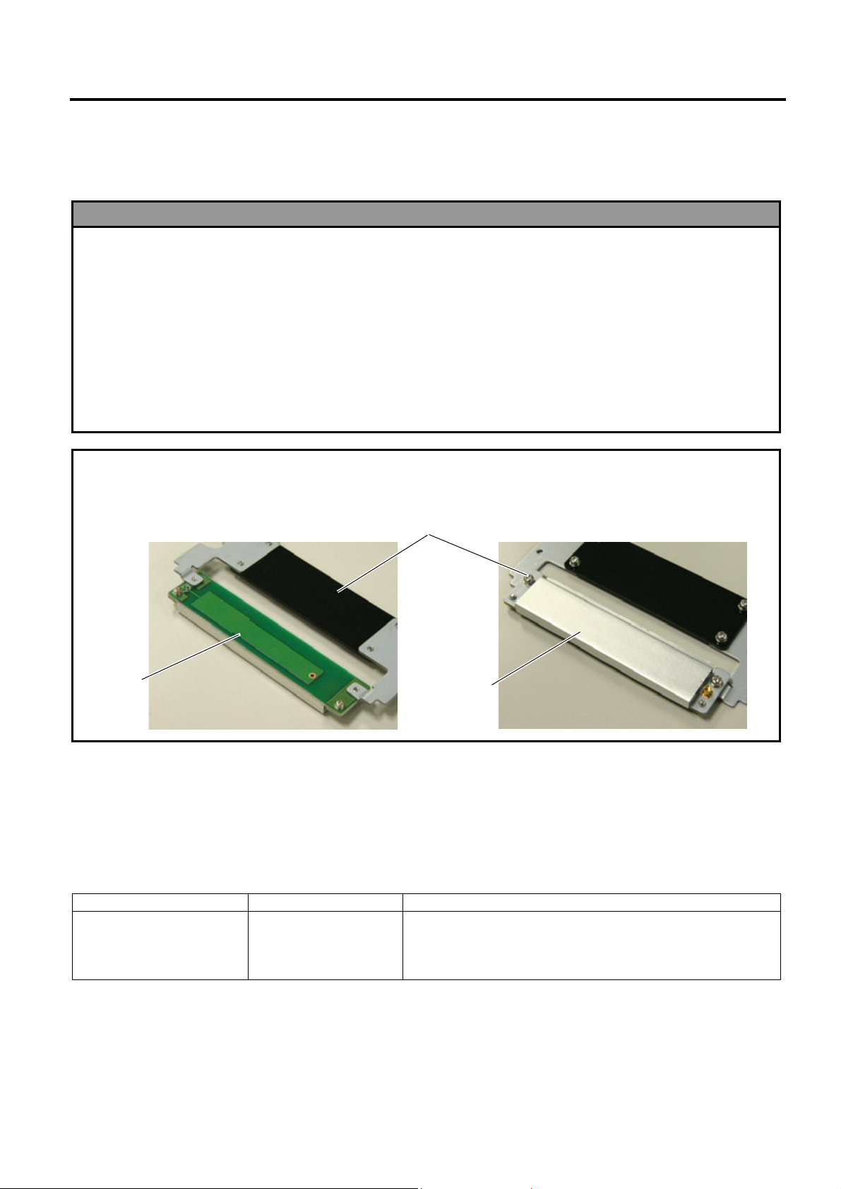
8. RFID Module: B-SA704-RFID-U2-EU-R
This optional device is intended for adding the RFID tag read/write function to the B-SA4TM and B-SA4TP series.
1. Follow all manual instructions. Failure to do so could create safety hazards such as fire or electrocution.
• Manual instructions must be followed when installing option kits or adding cables to avoid system
failures and to insure proper performance and operation.
• Failure to follow manual instructions or any unauthorized modifications, substitution or change to this
product will void the limited product warranty.
2. Turn the power OFF and disconnect the power cord before installing the RFID module.
3. Be careful not to pinch your fingers or hands with the covers.
4. The print head and stepping motor becomes very hot immediately after printing. Do not touch the print
head, stepping motor and around it right after printing, or you may get burned.
5. When opening the top cover, it must be fully opened. Failure to do this may cause the top cover to close
under its own weight, resulting in an injury.
CAUTION!
Be careful not to damage the pattern of the Antenna Ass’y or peel off the Shield Sheet. Damaged pattern or
removed Sheild Sheet may affect the ability to read or write RFID tags.
Pattern
WARNING!
Antenna Ass’y
Shield Shee
• Applicable Model
This optional device is intended for the following models:
Notes: 1. To use this device firmware V1.6 or greater is required. Upgrade the firmware to V1.6 or greater, if
necessary. For the downloading procedure, refer to the B-SA4T Series System Mode Manual.
2. The countries where the use of this device is allowed are as follows:
Model Name Frequency Band Applicable Countries
Austria, Belgium, Cyprus, Czech, Denmark, Estonia, Germany,
Greece, Finland, France, Hungary, Ireland, Italy, Latvia,
Lithuania, Luxemburg, Malta, Poland, Portugal, Slovakia,
Slovenia, Spain, Sweden, the Netherlands, and U.K.
8- 1
B-SA704-RFID–U2-EU-R
UHF 869.7 to
870.0MHz (Center
frequency:
869.85MHz)
Page 42

INSTALLATION PROCEDURE FOR OPTIONAL EQUIPMENT EO15-33001A
(Revision Date: Feb. 25, 2008)
8. RFID Module: B-SA704-RFID-U2-EU-R
• Packing List
All the following parts are supplied with the kit. Make sure you have all items shown below.
Parts (Quantity) Parts (Quantity) Parts (Quantity)
Antenna Ass’y (1 pc.)
Interface Cable (1 pc.)
Cable Clamp (1 pc.)
Tapping Screw M-3x8 (3 pcs.)
RFID Module (1 pc.)
Shield Sheet (for the use of short-pitch
tags) (1 pc.)
Edge Guard (Long and short: 2 pcs.
each)
Double Sems Screw M-3x6 (2 pcs.)
Antenna Cable (1 pc.)
RFID Module Attaching Plate (1 pc.)
Installation Manual (1 copy)
8- 2
Page 43

INSTALLATION PROCEDURE FOR OPTIONAL EQUIPMENT EO15-33001A
(Revision Date: Feb. 25, 2008)
8. RFID Module: B-SA704-RFID-U2-EU-R
• Outline of the introduction of an RFID Kit
Please follow the steps below to install the RFID kit, configure various settings, and try data write onto tags.
(1) Install the RFID kit. (Refer to this section.)
(2) Set an RFID module type, tag type, etc. in the printer system mode. (Refer to this section or section 2.9
of system mode manual.)
(3) In the printer system mode, perform a read test to confirm the printer acknowledges the RFID module.
(Refer to section 2.9 of system mode manual.)
(4) Discover an optimum feed amount and output power of the RFID module for data read/write using the
RFID Analyze Tool. (Refer to section 5 of system mode manual.)
(5) Set the feed amount by using an RFID Tag Position Adjustment Command ([ESC]@003) and the
output power of the RFID module by using an RFID Parameter Set Command ([ESC]Z2;3) or printer
system mode, respectively. For details of the commands, refer to the B-SA4T Series External
Equipment Interface Specification.
(6) Try tag read/write with an application.
(7) If data write fails, set an AGC thre shold. (Refer to this section.)
• Installation Procedure
1. Remove the two screws from the back of the printer.
SMW-3x6 Screw
Side Panel
8- 3
Page 44

INSTALLATION PROCEDURE FOR OPTIONAL EQUIPMENT EO15-33001A
w
r
k
(Revision Date: Feb. 25, 2008)
8. RFID Module: B-SA704-RFID-U2-EU-R
2. Remove the Side Panel in the following order. Please note the procedure is different between the B-
SA4TM series and the B-SA4TP series.
B-SA4TM B-SA4TP
1. Open the Top Cover and Front Cover.
Top Cover
2. Remove the two SMW-3x6 screws which secure
the Side Panel.
Side Panel
Front Cover
SMW-3x6 Screw
3. Close the Front Cover and remove the Side Panel.
SMW-3x6 Scre
Side Panel
Open the Top Cover. Slide the Side Panel backward,
and then remove it in the direction of arrow A.
Top Cove
Side Panel
A
Reverse side of Side Panel
Side Panel
Hoo
8- 4
Page 45

INSTALLATION PROCEDURE FOR OPTIONAL EQUIPMENT EO15-33001A
y
y
(Revision Date: Feb. 25, 2008)
8. RFID Module: B-SA704-RFID-U2-EU-R
3. Slightly push the Upper Sensor Lever inside (1), and open the Upper Sensor Ass’y (2).
Upper Sensor Ass’
(2)
Upper Sensor Lever
(1)
4. Pushing the tabs on the rear of the Media Sensor Block toward the front of the printer, slightly lift the
back of the Media Sensor Block, and remove it toward the printer back.
Media Sensor Block
Tab
Tab
5. Turn over the Media Sensor Block, and secure the Antenna Ass’y with the supplied three Tapping
Screws.
Sensor Block
Antenna Ass’
Tapping Screw M-3x8
Tapping Screw M-3x8
8- 5
Page 46

INSTALLATION PROCEDURE FOR OPTIONAL EQUIPMENT EO15-33001A
r
(Revision Date: Feb. 25, 2008)
8. RFID Module: B-SA704-RFID-U2-EU-R
6. As the following picture shows, pass the Interface Cable through the opening behind the Stepping
Motor so that the cable reaches the Main PC Board.
Opening
Interface Cable
Stepping Moto
7. Connect the Interface Cable to CN6 on the Main PC Board.
CN6
Main PC Board
Interface Cable
8. Put the Interface Cable on the hooks provided on the Media Path Frame.
Media Path Frame
Hook
Interface Cable
8- 6
Page 47

INSTALLATION PROCEDURE FOR OPTIONAL EQUIPMENT EO15-33001A
A
(Revision Date: Feb. 25, 2008)
8. RFID Module: B-SA704-RFID-U2-EU-R
9. Fit the supplied Edge Guards on the metal plate all the way to their bottoms.
• Please be careful not to injure your hands while fitting the Edge Guards.
• Fit the long Edge Guards and short ones on the correct positions respectively, as indicated in the
pictures below.
• The Edge Guards should not protrude from the edge of the metal plate (portions enclosed with
circles).
Short
Long
Short
Long
Edge Guard
10. Attach the Cable Clamp to the position shown below.
Cable Clamp
11. Temporarily secure the RFID Module Attaching Plate to the RFID Module with a supplied Double
Sems Screw. Connect the Antenna Cable to the RFID Module until it clicks.
ntenna Cable
RFID Module
Attaching Plate
Double Sems Screw M-3x6
RFID Module
8- 7
Page 48

INSTALLATION PROCEDURE FOR OPTIONAL EQUIPMENT EO15-33001A
(Revision Date: Feb. 25, 2008)
8. RFID Module: B-SA704-RFID-U2-EU-R
12. Connect the Interface Cable to the RFID Module.
Interface Cable
RFID Module
13. Secure the RFID Module to the printer with a supplied Double Sems Screw.
Double Sems Screw
M-3x6
RFID Module
14. While pushing down the RFID Module, tighten the Double Sems Screw, which was temporarily
tightened in Step 10, so that there is no clearance between the RFID Module and the Bottom Plate
of the printer.
RFID Module
RFID Module Attaching Plate
Double Sems Screw
M-3x6
Bottom Plate
8- 8
Page 49

INSTALLATION PROCEDURE FOR OPTIONAL EQUIPMENT EO15-33001A
A
r
(Revision Date: Feb. 25, 2008)
8. RFID Module: B-SA704-RFID-U2-EU-R
15. Re-place the Media Sensor Block.
Media Sensor Block
16. Connect the Antenna Cable to the Antenna Ass’y until it clicks, and fasten the Antenna Cable with the
Cable Clamp, as shown below.
ntenna Cable
Antenna Ass’y
Cable Clamp
17. Reattach the Side Panel to the printer with reference to Step 2.
18. Close the Front Cover and the Top Cover. Now, an installation of the RFID Module has been finished.
In the case short-pitch RFID tags (20mm) are used, refer to Section 4 to attach the Shield Sheet and
Section 5 to configure the RFID module settings.
When short-pitch tags are not used, refer to Section 5 to configure the RFID module settings.
• When Short-Pitch RFID Tags (20mm) are used:
When short-pitch tags (20 mm) are used, the supplied Shield Sheet needs to be attached for proper
read/write operation.
Follow the procedure below to attach the Shield Sheet to the Media Guide Bock.
1. Before attaching the Shield Sheet, move the Media Sensor to the right-most position. Failure to do this
disables a media sensor position adjustment.
Media
Senso
8- 9
Page 50

INSTALLATION PROCEDURE FOR OPTIONAL EQUIPMENT EO15-33001A
(Revision Date: Feb. 25, 2008)
8. RFID Module: B-SA704-RFID-U2-EU-R
2. Insert the Shield Sheet, without the backing paper removed, under the Media Guides from behind, and
slightly slide it toward the Platen. Then, move the Media Guides to the width of the Shield Sheet
(shorter width), as the pictures show. The purpose of this is to indicate the center of the attachment
position.
Platen
Media Guide
Shield Sheet
Media Guide
Media Guide
Shield Sheet
3. Remove the backing paper from the Shield Sheet, and attach it to the position determined in the
previous step, as indicated in the picture below. Now, the Shield Sheet attachment is completed.
Next, refer to Section 5 and configure the RFID module settings.
Media Guide Block
Shield Sheet
8- 10
Page 51

INSTALLATION PROCEDURE FOR OPTIONAL EQUIPMENT EO15-33001A
(Revision Date: Feb. 25, 2008)
8. RFID Module: B-SA704-RFID-U2-EU-R
• RFID Module Settings
After installing the RFID Module on the printer, configure the RFID module settings using the system mode
on the printer.
Turn on the printer while holding
down the [FEED] and [PAUSE]
keys at the same time.
<1>DIAG. V1.6
When “<1>DIAG. V1.6“ appears on the LCD, press the [RESTART] key.
[RESTART]
<10>RFID
[PAUSE]
<10>RFID
READ TEST OFF
RFID setting menu ”<10>RFID” is displayed.
Press the [PAUSE] key.
Read test menu is displayed. Choose whether to perform a read test or not with
the [RESTART] or [FEED] key.
[RESTART]
[FEED]
READ TEST OFF
READ TEST ON
[PAUSE]
<10>RFID
CAREERSENSE OFF
[PAUSE]
<10>RFID
MODULE NONE
[PAUSE]
Continued to the next
page.
OFF: A read test is not performed. (Initially, choose “OFF”.)
ON: A read test is performed.
The printer enters the read test mode, and a read test is performed each time the
[PAUSE] key is pressed. When the data of a tag can be read, it is displayed on the
LCD.
• Read data is displayed in hex. value on the 16-digit x 2-line LCD.
1234567890123456
6543210987654321
When the RFID tag contains 16 digits or more data, the first 16 digits are displayed.
When data volume is less than 16 digits, the vacant digits will be filled with spaces.
• If the tag cannot be read, “RFID TIMEOUT” or “RFID READ ERROR” is displayed.
• If the type of the tag to be read and one selected by the RFID tag t ype selection do not
match, an RFID tag read error will result.
Make sure the RFID tag type has been selected before the read test is started.
After choosing an option, press the [PAUSE] key.
Carrier sense setting menu is displayed. This menu is not available to the B-SA704-RFIDU2-EU-R. Press the [PAUSE] key to skip this menu.
Module type setting menu is displayed. Choose “U2” with the [FEED] or [RESTART] key.
[RESTART]
[FEED]
Press the [PAUSE] key.
U1: Not available.
H1: not available.
NONE: No RFID Module is installed.
U2: B-SA704-RFID-U2-EU-R
H2: Not available.
8- 11
Page 52

INSTALLATION PROCEDURE FOR OPTIONAL EQUIPMENT EO15-33001A
f
r
(Revision Date: Feb. 25, 2008)
8. RFID Module: B-SA704-RFID-U2-EU-R
Continued from the
previous page.
<10>RFID
TAG NONE
RFID tag type setting menu is displayed.
Choose “EPC C1 Gen2: 24” with the [FEED] or [RESTART] key.
[PAUSE]
Press the [PAUSE] key.
[RESTART]
[FEED]
NONE: When a tag type is not selected.
EPC C1 Gen2: 24
<10>RFID
ERR CHK OFF
RFID error tag detection menu is displayed. Choose whether to perform an error tag
detection or not with the [FEED] or [RESTART] key.
[RESTART]
[FEED]
OFF: An error tag detection is not performed. (Usually,
choose OFF.)
ON: An error tag detection is performed.
[PAUSE]
ON: A tag is read before writing data on it, an d data is written on the tag only when the
header data is “A5A5”.
OFF: Though a tag is read before writing data on it, data write is always performed
whatever data has been set as the header data.
Press the [PAUSE] key.
<10>RFID
ISSUE RETRY 3
[PAUSE]
Max. number of issue retries setting menu is displayed.
Set the maximum number of retries to issue an RFID tag.
When issuing an RFID tag failed, the printer prints the error pattern, and retries to issue
the tag for up to specified number of times. If the printer does not succeed even after
having retried for the max. times, the printer stops, resulting in an error.
Choose the max. number of retries with the [FEED] or [RESTART] key.
255
[RESTART]
[FEED]
Press the [PAUSE] key.
•
•
•
3 (Default)
•
•
0
<10>RFID
R CYCLE CNT 5
Continued to the next page.
[PAUSE]
Max. number of read retries setting menu is displayed.
Set the maximum number of retries to read an RFID tag.
The printer retries to read the data in an RFID tag for up to specified number of times. I
the timeout period expired before the max. number retries have been done, the printe
stops the retries at the time.
Whenever the printer writes data onto an RFID tag, the tag is read
first. The max. number of retries set by this parameter becomes also
effective in this pre-read.
Choose the max. number of retries with the [FEED] or [RESTART] key.
255
[RESTART]
[FEED]
Press the [PAUSE] key.
•
•
•
5 (Default)
•
•
0
8- 12
Page 53

INSTALLATION PROCEDURE FOR OPTIONAL EQUIPMENT EO15-33001A
(Revision Date: Feb. 25, 2008)
8. RFID Module: B-SA704-RFID-U2-EU-R
Continued from the
previous page.
<10>RFID
R CYCLE TIM 4.0
[PAUSE]
Read retry timeout setting menu is displayed.
Set the timeout period during which RFID tag read retries are allowed, with the [FEED] or
[RESTART] key. If the printer has retried for the max. number of times within the RFID
read retry timeout, the printer stops the retries at the time.
Whenever the printer writes data onto an RFID tag, the tag is read first. The read retry
timeout set by this parameter becomes also effective in this pre-read.
9.9 (9.9
[RESTART]
[FEED]
Press the [PAUSE] key.
sec.)
•
•
•
4.0 (Default)
•
•
<10>RFID
W CYCLE CNT 5
[PAUSE]
<10>RFID
W CYCLE TIM 2.0
[PAUSE]
Max. number of write retries setting menu is displayed.
Set the maximum number of retries to write data onto an RFID tag.
The printer retries to write data onto an RFID tag for up to specified number of times. If
the timeout period expired before the max. number of retries have been done, the printer
stops the retries at the time.
Set the max. number of times with the [FEED] or [RESTART] key.
255
[RESTART]
[FEED]
Press the [PAUSE] key.
Write retry timeout setting menu is displayed.
Set the timeout period during which RFID tag write retries are allowed, with the [FEED] or
[RESTART] key.
If the printer has retried for the max. number of times within the RFID write retry timeout,
the printer stops the retries at the time.
[RESTART]
[FEED]
Press the [PAUSE] key.
•
•
•
5 (Default)
•
•
0
9.9 (9.9 sec.)
•
•
•
2.0 (Default)
•
•
0.0 (0.0 sec.)
Continued to the next page.
8- 13
Page 54

INSTALLATION PROCEDURE FOR OPTIONAL EQUIPMENT EO15-33001A
A
A
(Revision Date: Feb. 25, 2008)
8. RFID Module: B-SA704-RFID-U2-EU-R
Continued from the
previous page
<10>RFID
DJ RETRY +00
[PAUSE]
<10>RFID
POWER LEVEL 18
[PAUSE]
<10>RFID
GC THRESHOLD 0
RFID adjustment for retry menu is displayed.
If writing data on a tag failed, the printer feeds the RFID tag forward or backward for
specified length in order to retry writing data. When “0” is set for this parameter, this
function and a retry are not performed.
Only the value of –3mm or less or +3mm or more becomes effective.
Set a value to move the RFID tag position with the [FEED] or [RESTAT] key.
+99 (99mm) Reverse feed
[RESTART]
[FEED]
-99 (-99mm) Forward feed
Press the [PAUSE] key.
Radio output power level setting menu is displayed.
When the value is “9”, the power is the weakest, and when “18”, the power is the
strongest. The factory default setting is “18”. The optimum value differs depending on the
tag types. Usually, it is not necessary to change this value but changing the value may be
able to increase the number of successful read/write times.
Set the power level with the [FEED] or [RESTART] key.
18 (Default, Strongest)
[RESTART]
[FEED]
Press the [PAUSE] key.
AGC threshold setting menu is displayed.
When the obtained gain of an RFID tag is lower than the AGC threshold, the tag is
considered as an error tag even if a data write succeeds.
When the AGC threshold is set to “0”, all tags are writable.
When set to “8”, for example, only tags with the AGC threshold level of 9 or greater are
writable. The optimum value is different depending on the tag types. The factory default is 0.
Set an AGC threshold with the [FEED] or [RESTART] key.
•
•
•
+00 (Default)
•
•
•
•
•
•
•
9 (Weakest)
[RESTART]
[FEED]
15
•
•
•
•
•
0 (Default)
[PAUSE]
Press the [PAUSE] key.
<10>RFID
RF CHANNEL AUTO
RFID channel setting menu is not available to the B-SA704-RFID-U2-EU-R.
[PAUSE]
Press the [PAUSE] key to skip this menu.
Continued to the next page.
8- 14
Page 55

INSTALLATION PROCEDURE FOR OPTIONAL EQUIPMENT EO15-33001A
r
(Revision Date: Feb. 25, 2008)
8. RFID Module: B-SA704-RFID-U2-EU-R
Continued from the
previous page.
<10>RFID
Q VALUE 2
[PAUSE]
<10>RFID
WT AGC 11
[PAUSE]
<10>RFID
WT MIN AGC 11
[PAUSE]
<10>RFID
Q value setting menu is displayed.
In the case multiple RFID tags are read at the same time, this menu is useful to pinpoint a
target tag.
Set the Q value to “1” or greater (2 is recommended.) with the [FEED] or [RESTART] key.
Q value “0” causes the tags to interfere with each other and disables proper data write.
When a Q value is set, set an AGC threshold for data write and an AGC threshold lo we
limit for retry, also. Setting all these values enable writing data to a tag p laced just above
the antenna. (For details, refer to Section 6. AGC Threshold Setting.)
The factory default is 2.
15
[RESTART]
[FEED]
Press the [PAUSE] key.
AGC threshold for data write setting menu is displayed.
When the Q value is set to 1 or greater, the AGC threshold for data write becomes
effective.
When the obtained gain of an RFID tag is lower than the AGC thresholdfor data write, data
write is not performed. In other words, setting an AGC threshold for data write enables
writing data only to a tag placed just above the antenna.
The optimum value differs depending on the tag type.
(For details, refer to Section 6. AGC Threshold Setting.)
Set an AGC threshold for data write with the [FEED] or [RESTART] key, if necessary.
[RESTART]
[FEED]
Press the [PAUSE] key.
AGC threshold lower limit for retry setting menu is displayed.
When the Q value is set to 1 or greater, the AGC threshold lower limit for retry becomes
effective.
When there are tags of which AGC values fall within the range between the AGC threshold
for data write and the lower limit, the printer retries data write for a tag with the high est
AGC value among those tags. When printer retries data write, that value is then used as
an AGC threshold.
The optimum value differs depending on the tag type.
(For details, refer to Section 6. AGC Threshold Setting.)
Set the lower limit for retry with the [FEED] or [RESTART] key, if necessary.
[RESTART]
[FEED]
Press the [PAUSE] key.
The LCD message returns to ”<10>RFID”.
Now, the RFID module settings are completed. If data write to RFID tags cannot be
properly performed, refer to Section 5.
•
•
2 (Default)
•
•
0
15
•
•
11 (Default)
•
•
0
15
•
•
11 (Default)
•
•
0
8- 15
Page 56

INSTALLATION PROCEDURE FOR OPTIONAL EQUIPMENT EO15-33001A
r
(Revision Date: Feb. 25, 2008)
8. RFID Module: B-SA704-RFID-U2-EU-R
• AGC Threshold Setting
The B-SA704-RFID-U2-EU-R chooses a tag to write data on according to a radio intensity of RFID tags (AGC
value).
An AGC threshold value has been set to 11 (0Bh) as factory default, but it may be necessary to change this value
according to the tag type to be used.
When the factory default threshold value is not proper for the tag type used, follow the procedure below to
configure the following settings.
As the changes are stored in the internal memory, they are retained after the printer power is turned off and on
again. When the tag type is changed or data write cannot be operated properly, perform the setting again.
Step 1. Load an RFID tag embedded media in the printer.
Step 2. Follow the procedure below to measure the radio intensity of the tags.
1) Place the media so that an RFID tag (IC chip) is positioned above the Antenna, and close the Top
Cover.
Note: If an RFID tag is not positioned above the Antenna while the Print Head is at a print start position,
use @003 command to adjust the media position so that an RFID tag is positioned above the
Antenna. For detail of the command, refer to the External Equipment Interface Specification
(Printer Command Manual).
2) Start the printer in the system mode and perform a read test to measure the AGC value.
Example
Continued to the next page
Printe
Print Head
RFID
Platen
Antenna
Antenna Cable
RFID Module
Turn the printer on while holding down the
[FEED] and [PAUSE] keys at the same time.
<1>DIAG. V1.6
[RESTART]
<10>RFID
[PAUSE]
<10>RFID
READ TEST OFF
[FEED] or [RESTAT]
<10>RFID
READ TEST ON
[PAUSE]
<10>RFID
READING•••.
Tag
When “<1>DIAG. V1.6” is displayed, press the [RESTART] key.
When “<10>RFID” is displayed, press the [PAUSE] key.
Read test menu is displayed.
Press the [FEED] or [RESTAT] key to choose “READ TEST ON”.
Press the [PAUSE] key to implement a read test.
Media
8- 16
Page 57

INSTALLATION PROCEDURE FOR OPTIONAL EQUIPMENT EO15-33001A
A
r
A
A
(Revision Date: Feb. 25, 2008)
8. RFID Module: B-SA704-RFID-U2-EU-R
Continued from the previous page
3132333435363738
39304142 (0A)
[FEED], [RESTART]
<10>RFID
Read data is displayed.
Data in parentheses ( ) is the AGC value expressed in hex. code.
Write down this value.
Press the [FEED] and [RESTART] keys to return to the RFID
Setting Menu (”<10>RFID”).
3) Set an AGC threshold of data write.
Set a value which is lower than the AGC value obtained by a read test by 1 or 2, taking variation of
RFID tags in performance into consideration.
Example
<10>RFID
[PAUSE]
<10>RFID
Q VALUE 2
[FEED] or [RESTART]
<10>RFID
Q VALUE 2
[PAUSE]
<10>RFID
WT AGC 11
[FEED] or [RESTAT]
<10>RFID
WT AGC 9
[PAUSE]
<10>RFID
WT MIN AGC 11
[FEED] or [RESTAT]
<10>RFID
WT MIN AGC 9
[PAUSE]
<10>RFID
When ”<10>RFID” is displayed, press the [PAUSE] key until the Q
value setting menu is displayed.
Choose “2” with the [FEED] or [RESTART] key.
When “2” is already chosen, go to the AGC threshold for data write
setting menu.
15
[RESTART]
[FEED]
Press the [PAUSE] key.
GC threshold for data write setting menu is displayed.
Choose a threshold value (decimal number) with the [FEED] o
[RESTART] key.
When the measured AGC is 10 (0A), for example, choose “9” (a
value lower than the measured AGC by 1 or 2).
[RESTART]
[FEED]
Press the [PAUSE] key.
GC threshold lower limit for retry setting menu is displayed.
Choose a lower limit (decimal number) with the [FEED] or
[RESTART] key.
Usually, choose the same value with the AGC threshold for data
write (WT AGC).
[RESTART]
[FEED]
Press the [PAUSE] key.
RFID Setting Menu (”<10>RFID”) is displayed.
n AGC threshold setting is completed.
•
•
2 (Default)
•
•
0
15
•
•
11 (Default)
•
•
0
15
•
•
11 (Default)
•
•
0
8- 17
Page 58

INSTALLATION PROCEDURE FOR OPTIONAL EQUIPMENT EO15-33001A
(Revision Date: Nov. 7, 2008)
8. RFID Module: B-SA704-RFID-U2-EU-R
• Identification of The Rfid Module (B-SA704-RFID-U2-EU-R)
As from the production manufactured in October 2008, the standard label has been added to the RFID
module, which is used for the B-SA4T series, for improving the efficiency of assembly.
RFID Module
Service No. Label
B-SA704-RFID-U2-EU-R
Serial No. Label
Note: Descriptio of the serial number label and service number label
Description of Service Number Label
Description of Serial Number Label
B-SA704-RFID-U2-EU-R
B-0500-02
Service number
B-05000-01: For EU
B-SA704-RFID-U2-EU-R
08 5 D XXXX
Module type
C: EU
Month
1~9, A (10), B (11), C (12)
Least 2 digit of the Christian Era
Serial number
8- 18
 Loading...