

Page 1
TOSHIBA Barcode Printer
B-FV4D SERIES
Owner’s Manual
Page 2
CE Compliance (for EU only)
)
This product complies with the requirements of EMC and Low Voltage Directives including their amendments.
CE marking is the responsibility of TOSHIBA TEC GERMANY IMAGING SYSTEMS GmbH, Carl-Schurz-Str. 7,
41460 Neuss, Germany.
For a copy of the related CE Declaration of Conformity, please contact your dealer or TOSHIBA TEC.
This is a Class A product. In a domestic environment this product may cause radio interference in which case
the user may be required to take adequate measures.
FCC Notice
This equipment has been tested and found to comply with the limits for a Class A digital device, pursuant to
Part 15 of the FCC Rules. These limits are designed to provide reasonable protection against harmful
interference when the equipment is operated in a commercial environment. This equipment generates, uses,
and can radiate radio frequency energy and, if not installed and used in accordance with the instruction
manual, may cause harmful interference to radio communications. Operations of this equipment in a
residential area is likely to cause harmful interference in which case the user will be required to correct the
interference at his own expense.
WARNING
Changes or modifications not expressly approved by the party responsible for compliance could void the user's
authority to operate the equipment.
CAN ICES-3 (A) / NMB-3 (A)
This Class A digital apparatus complies with Canadian ICES-003.
(for USA only)
(for CANADA only)
The EA1050B-240 AC adapter should be exclusively used for the B-FV4D-xxxx-QM-R Series printer.
The B-FV4D-xxxx-QM-R Series printer must be powered by the EA1050B-240 AC adapter.
The EA10681P-240 AC adapter should be exclusively used for the B-FV4D-xxxx-QQ-R Series printer.
The B-FV4D-xxxx-QQ-R Series printer must be powered by the EA10681P-240 AC adapter.
California Proposition 65 Warning: USA-California only
This Product contains chemicals known to the State of California to cause cancer, birth defects, or other
reproductive harm.
The following information is for EU-member states only:
Disposal of products
(based on EU-Directive 2002/96/EC,
Directive on Waste electrical and electronic equipment –WEEE
The use of the symbol indicates that this product may not be disposed as unsorted municipal waste and
has to be collected separately. Integrated batteries and accumulators can be disposed of with the
product. They will be separated at the recycling centers.
The black bar indicates that the product was placed on the market after August 13, 2005.
By ensuring this product is disposed of correctly, you will help prevent potential negative consequences
for the environmental and human health, which could otherwise be caused by inappropriate waste
handling of this product.
For more detailed information about the take-back and recycling of this product, please contact your
supplier where you purchased this product.
Notification (for Turkey)
AEEE Yönetmeliğine Uygundur
Following information is only for India:
The use of the symbol indicates that this product may not be treated as household waste. By ensuring this
product is disposed of correctly, you will help prevent potential negative consequences for the environment
and human health, which could otherwise be caused by inappropriate waste handling of this product.
For more detailed information about the take-back and recycling of this product, please contact your
supplier where you purchased the product.
This product complies with the “India E-waste Rule 2011” and prohibits use of lead, mercury, hexavalent
chromium, polybrominated biphenyls or polybrominated diphenyl ethers in concentrations exceeding 0.1%
by weight and 0.01% by weight for cadmium, except for the exemption set in Schedule II of the Rule.
This product is designed for commercial usage and is not consumer product.
Page 3

Precautions for the handling of Wireless Communication Devices
This product is classified as “wireless equipment for stations of low-power data transmissions systems” under the
Wireless Telegraphy Act, and does not require a radio transmission license. The law prohibits modification of the
interior of this product.
Regulatory Information
This product must be installed and used in strict accordance with the manufacturer’s instructions as described in
the user documentation that comes with the product. This device complies with the following radio frequency and
safety standards.
Standards below are certified under the operation with the provided antenna. Do not use this product with other
antennas.
Europe - EU Declaration of Conformity
Hereby, TOSHIBA TEC, declares that B-FV4D / B-FV4T series are in compliance with the essential requirements
and other relevant provisions of Directive 2014/53/EU.
USA-Federal Communications Commission (FCC)
NOTE: This equipment has been tested and found to comply with the limits for a Class A digital device, pursuant
to part 15 of the FCC Rules. These limits are designed to provide reasonable protection against harmful
interference when the equipment is operated in a commercial environment. This equipment generates, uses, and
can radiate radio frequency energy and, if not installed and used in accordance with the instruction manual, may
cause harmful interference to radio communications. Operation of this equipment in a residential area is likely to
cause harmful interference in which case the user will be required to correct the interference at his own expense.
CAUTION:
This device complies with Part 15 of the FCC Rules.
Operation is subject to the following two conditions:
(1) this device may not cause harmful interference, and
(2) this device must accept any interference received, including interference that may cause undesired operation.
Any changes or modifications not expressly approved by the grantee of this device could void the user's authority
to operate the equipment.
RF EXPOSURE WARNING:
This equipment must be installed and operated in accordance with provided instructions and the antenna(s) used
for this transmitter must be installed to provide a separation distance of at least 20 cm from all persons and must
not be co-located or operating in conjunction with any other antenna or transmitter. End-users and installers must
be provide with antenna installation instructions and transmitter operating conditions for satisfying RF exposure
compliance.
Canada - Industry Canada (IC)
This device complies with Canada licence-exempt RSS standard(s).
Operation is subject to the following two conditions:
(1) this device may not cause interference, and
(2) this device must accept any interference, including interference that may cause undesired operation of the
device.
Cet appareil est conforme avec Industrie Canada exemptes de licence RSS standard(s).
Son fonctionnement est soumis aux deux conditions suivantes:
(1) cet appareil ne doit pas causer d'interférence et
(2) cet appareil doit accepter toute interférence, notamment les interférences qui peuvent affecter son
fonctionnement.
Radio Frequency (RF) Exposure Information
The radiated output power of the Wireless Device is below the Industry Canada (IC) radio frequency exposure
limits. The Wireless Device should be used in such a manner such that the potential for human contact during
normal operation is minimized.
This device has also been evaluated and shown compliant with the IC RF Exposure limits under mobile exposure
conditions. (antennas are greater than 20cm from a person's body).
Page 4

Informations concernant l'exposition aux fréquences radio (RF)
La puissance de sortie émise par l’appareil de sans fil est inférieure à la limite d'exposition aux fréquences radio
d'Industry Canada (IC). Utilisez l’appareil de sans fil de façon à minimiser les contacts humains lors du
fonctionnement normal.
Ce périphérique a également été évalué et démontré conforme aux limites d'exposition aux RF d'IC dans des
conditions d'exposition à des appareils mobiles (antennes sont supérieures à 20 cm à partir du corps d'une
personne).
Approved Countries/Regions for use for the devices
This equipment is approved to the radio standard by the specific countries/regions. Please ask TOSHIBA TEC
authorized dealer or service engineer.
Precaution for Use
This product communicates with other devices by radio. Depending on the installation location, orientation,
environment, etc., its communication performance may deteriorate or devices installed near by may be affected.
Bluetooth® and Wireless LAN devices operate within the same radio frequency range and may interfere with one
another. If you use Bluetooth® and Wireless LAN devices simultaneously, you may occasionally experience a
less than optimal network performance or even lose your network connection.
If you should experience any such problem, immediately turn off your Bluetooth® or Wireless LAN device.
Keep away from a microwave.
Communication performance may deteriorate or a communication error may occur due to the radio emitted from
a microwave.
Do not use the product on a metal table or near a metal object. Communication performance may be deteriorated.
* Bluetooth® is a registered trademark owned by Bluetooth SIG, Inc.
Page 5
Safety Precautions ENGLISH VERSION
W
W
Safety Summary
Personal safety in handling or maintaining the equipment is extremely important. Warnings and Cautions necessary for safe
handling are included in this manual. All warnings and cautions contained in this manual should be read and understood
before handling or maintaining the equipment.
Do not attempt to effect repairs or modifications to this equipment. If a fault occurs that cannot be rectified using the
procedures described in this manual, turn off the power, unplug the machine, and then contact your authorised TOSHIBA
TEC CORPORATION representative for assistance.
Meanings of Each Symbol
This symbol indicates a potentially hazardous situation which, if not avoided, could
result in death, serious injury, or serious damage, or fire in the equipment or surrounding
objects.
This symbol indicates a potentially hazardous situation which, if not avoided, may result
in minor or moderate injury, partial damage to the equipment or surrounding objects, or
loss of data.
This symbol indicates prohibited actions (prohibited items).
Specific prohibited contents are drawn inside or near the
(The symbol on the left indicates “no disassembling”.)
symbol.
This symbol indicates actions which must be performed.
Specific instructions are drawn inside or near the symbol.
(The symbol on the left indicates “disconnect the power cord plug from the outlet”.)
ARNING
CAUTION
PROHIBITED
MUST be
Performed
NOTE: Indicates information to which you should pay attention when operating the manual.
Any other than the
specified AC voltage
is prohibited.
Prohibited
Prohibited
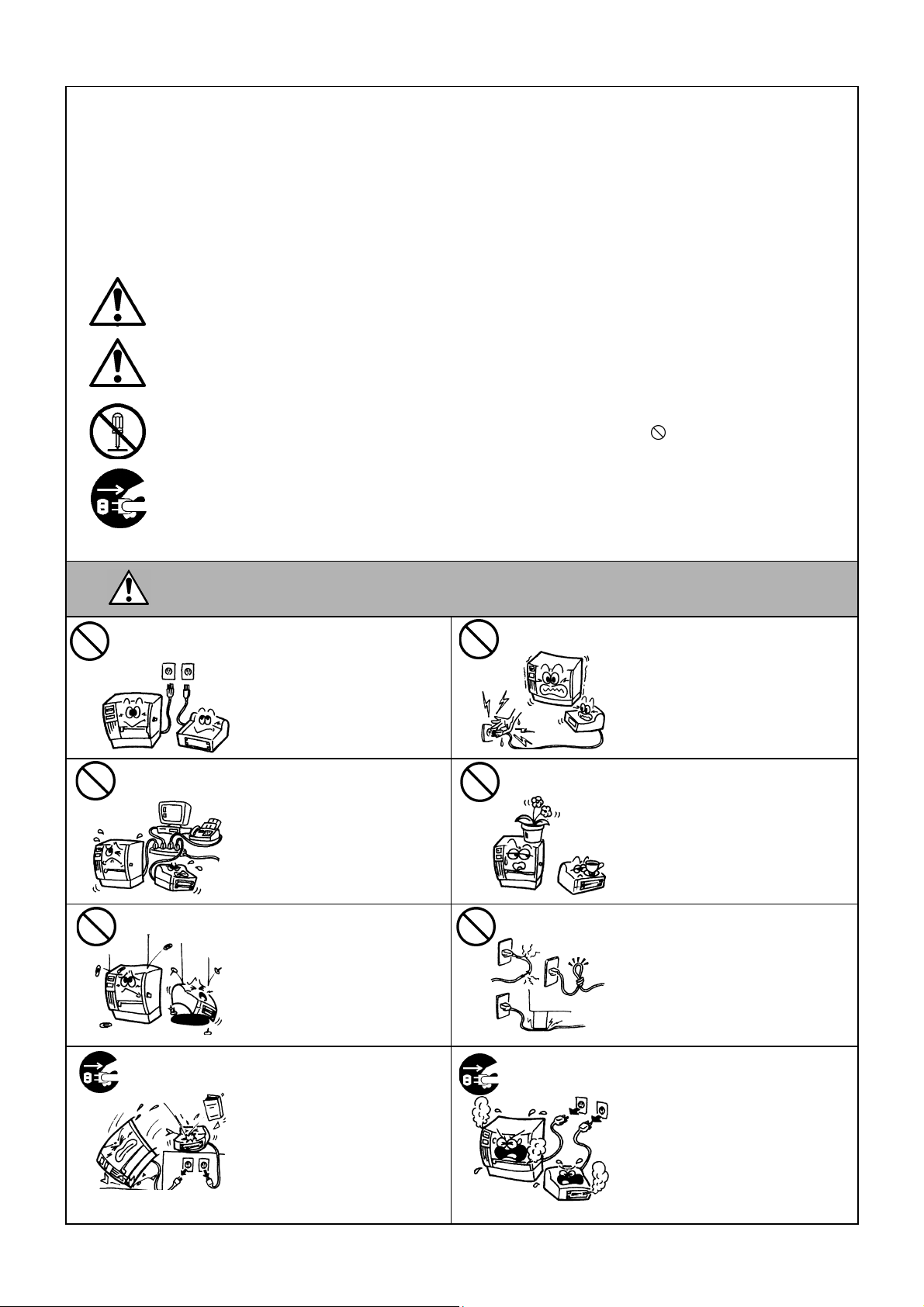
ARNING
Do not use voltages other than the
AC voltage specified on the rating
plate, as this may cause fire or
electric shock.
If the machine share the same
electrical outlet with any other
appliance that consumes a large
amount of power, the voltage will
fluctuate widely each time these
appliances operate. Be sure to
provide an exclusive outlet for the
machine as this may cause fire or
electric shock.
Do not insert or drop metal,
flammable or other foreign objects
into the machine through the
ventilation slits, as this may cause
fire or electric shock.
This indicates that there is the risk of death or serious injury if the
machine is improperly handled contrary to this indication.
Prohibited
Prohibited
Prohibited
Do not plug in or unplug the power
cord with wet hands as this may cause
electric shock.
Do not place metal objects or waterfilled containers such as flower vases,
flower pots or mugs, etc. on top of the
machine. If metal objects or spilled
liquid enter the machine, this may
cause fire or electric shock.
Do not scratch, damage or modify the
power cords. Also, do not place heavy
objects on, pull on, or excessively bend
the power cords, as this may cause fire
or electrical shock.
Disconnect
the plug.
If the machine is dropped or their
cabinet damaged, first turn off the
power switch and disconnect the
power cord plug from the outlet,
and then contact your authorised
TOSHIBA TEC CORPORATION
representative for assistance.
Continued use of the machine in
that condition may cause fire or
electric shock.
Disconnect
the plug.
Continued use of the machine in an
abnormal condition such as when the
machine is producing smoke or strange
smells may cause fire or electric
shock. In these cases, immediately
turn off the power switches and
disconnect the power cord plug from
the outlet. Then, contact your
authorised TOSHIBA TEC
CORPORATION representative for
assistance.
( i )
Page 6
Safety Precautions ENGLISH VERSION
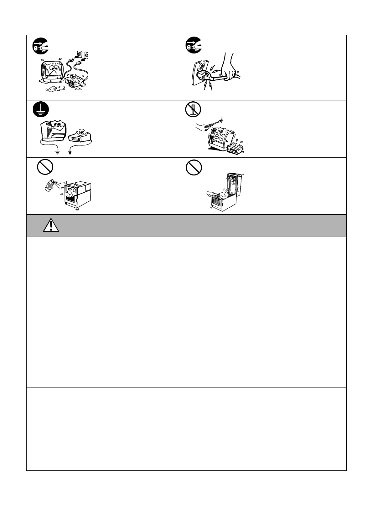
Disconnect
the plug.
Connect a
grounding wire.
If foreign objects (metal fragments,
water, liquids) enter the machine,
turn off the power switch and
disconnect the power cord plug
from the outlet, and then contact
your authorised TOSHIBA TEC
CORPORATION representative
for assistance. Continued use of
the machine in that condition may
cause fire or electric shock.
Ensure that the equipment is
properly grounded. Extension
cables should also be grounded.
Fire or electric shock could occur
on improperly grounded
equipment.
Disconnect
the plug.
No
disassembling.
When unplugging the power cords, be
sure to hold and pull on the plug.
Pulling on the cord may cut or expose
the internal wires and cause fire or
electric shock.
Do not remove covers, repair or
modify the machine by yourself.
Contact your authorised TOSHIBA
TEC CORPORATION representative
for assistance. You may be injured by
high voltage, very hot parts or sharp
edges inside the machine.
Prohibited
Do not use a spray cleaner
containing flammable gas for
cleaning this product, as this may
cause a fire.
Prohibited
Care must be taken not to injure
yourself with the printer paper cutter.
This indicates that there is the risk of personal Injury or damage to objects if the
CAUTION
machine is improperly handled contrary to this indication.
Precautions
The following precautions will help to ensure that this machine will continue to function correctly.
Try to avoid locations that have the following adverse conditions:
* Temperatures out of the specification * Direct sunlight * High humidity
* Shared power source * Excessive vibration * Dust/Gas
The cover should be cleaned by wiping with a dry cloth or a cloth slightly dampened with a mild detergent solution. NEVER USE
THINNER OR ANY OTHER VOLATILE SOLVENT on the plastic covers.
USE ONLY TOSHIBA TEC CORPORATION SPECIFIED paper and ribbons.
DO NOT STORE the paper or ribbons where they might be exposed to direct sunlight, high temperatures, high humidity, dust, or
gas.
Ensure the printer is operated on a level surface.
Any data stored in the memory of the printer could be lost during a printer fault.
Try to avoid using this equipment on the same power supply as high voltage equipment or equipment likely to cause mains
interference.
Unplug the machine whenever you are working inside it or cleaning it.
Keep your work environment static free.
Do not place heavy objects on top of the machine, as these items may become unbalanced and fall causing injury.
Do not block the ventilation slits of the machine, as this will cause heat to build up inside the machine and may cause fire.
Do not lean against the machine. It may fall on you and could cause injury.
Unplug the machine when it is not used for a long period of time.
Place the machine on a stable and level surface.
RISK OF EXPLOSION IF BATTERY IS REPLACED BY AN INCORRECT TYPE. DISPOSE OF USED BATTERIES
ACCORDING TO THE INSTRUCTIONS.
Request Regarding Maintenance
Utilize our maintenance services.
After purchasing the machine, contact your authorised TOSHIBA TEC CORPORATION representative for assistance once a year
to have the inside of the machine cleaned. Dust will build up inside the machine and may cause a fire or a malfunction. Cleaning is
particularly effective before humid rainy seasons.
Our preventive maintenance service performs periodic checks and other work required to maintain the quality and performance of
the machine, preventing accidents beforehand.
For details, please consult your authorised TOSHIBA TEC CORPORATION representative.
Using insecticides and other chemicals
Do not expose the machine to insecticides or other volatile solvents. This will cause the cabinet or other parts to deteriorate and
may cause the paint to peel.
( ii )
Page 7

ENGLISH VERSION EO1-33097
TABLE OF CONTENTS
Page
1. PRODUCT OVERVIEW .......................................................................................................... E1-1
1.1 Introduction .................................................................................................................... E1-1
1.2 Features ........................................................................................................................ E1-1
1.3 Unpacking ...................................................................................................................... E1-1
1.4 Accessories .................................................................................................................. E1-1
1.5 Appearance ................................................................................................................... E1-3
1.5.1 Dimensions ................................................................................................................. E1-3
1.5.2 Front View .................................................................................................................. E1-3
1.5.3 Rear View ................................................................................................................... E1-4
1.5.4 Interior ........................................................................................................................ E1-4
1.5.5 Button and Indicator Lamp ......................................................................................... E1-5
2. PRINTER SETUP ................................................................................................................... E2-1
2.1 Precautions .................................................................................................................... E2-1
2.2 Procedure before Operation .......................................................................................... E2-2
2.3 Turning the Printer ON/OFF .......................................................................................... E2-2
2.3.1 Turning ON the Printer ............................................................................................... E2-2
2.3.2 Turning OFF the Printer .............................................................................................. E2-3
2.4 Connecting Cables to the Printer ................................................................................... E2-4
2.5 Connecting the Power Adapter and the Power Cord ..................................................... E2-5
2.6 Opening/Closing the Top Cover .................................................................................... E2-6
2.7 Loading the Media ......................................................................................................... E2-7
2.8 Media Sensor Calibration, Self Print Test, and Dump Mode Utilities ........................... E2-15
2.8.1 Media Sensor Calibration ......................................................................................... E2-15
2.8.2 Self Print Test and Dump Mode ................................................................................ E2-16
3. MAINTENANCE ..................................................................................................................... E3-1
3.1 Cleaning ........................................................................................................................ E3-1
3.1.1 Print Head .................................................................................................................. E3-1
3.1.2 Sensors ...................................................................................................................... E3-2
3.1.3 Platen Roller ............................................................................................................... E3-2
3.1.4 Media Housing ............................................................................................................ E3-3
3.2 Care/Handling of the Media ........................................................................................... E3-4
4. TROUBLESHOOTING ........................................................................................................... E4-1
4.1 Troubleshooting Guide .................................................................................................. E4-1
4.2 Status Lamp .................................................................................................................. E4-2
4.3 Removing Jammed Media ............................................................................................. E4-3
APPENDIX 1 SPECIFICATIONS ................................................................................................ EA1-1
A1.1 Printer .......................................................................................................................... EA1-1
A1.2 Options ........................................................................................................................ EA1-3
A1.3 Media ........................................................................................................................... EA1-3
A1.3.1 Media Type ........................................................................................................... EA1-3
A1.3.2 Detection Area of the Feed Gap (Transmissive) Sensor ....................................... EA1-5
A1.3.3 Detection Area of the Black Mark (Reflective) Sensor .......................................... EA1-5
A1.3.4 Effective Print Area ............................................................................................... EA1-5
APPENDIX 2 INTERFACE .......................................................................................................... EA2-1
GLOSSARIES
Page 8

ENGLISH VERSION EO1-33097
NOTES:
• This manual may not be copied in whole or in part without prior written permission of TOSHIBA TEC
CORPORATION.
• The contents of this manual may be changed without notification.
• Please refer to your local Authorized Service representative with regard to any queries you may have in this
manual.
• Centronics is a registered trademark of Centronics Data Computer Corp.
• Windows is a registered trademark of Microsoft Corporation.
Page 9

1. PRODUCT OVERVIEW ENGLISH VERSION EO1-33097
1. PRODUCT OVERVIEW
1.1 Introduction
1.2 Features
1.3 Unpacking
1.4 Accessories
Thank you for choosing the TOSHIBA B-FV4D series barcode printer.
This Owner’s Manual contains valuable information from general set-up
to confirming the printer's operation using test prints. You should read it
carefully to help you gain maximum performance and life from your
printer. This manual should be kept close at hand for everyday reference.
Please contact your TOSHIBA TEC CORPORATION representative for
further information concerning this manual.
This printer has the following features:
Interfaces
The printer comes fitted with a USB port and Ethernet port interfaces as
standard. Moreover, it contains either a Serial (RS-232C) or a Centronics
interface
Bluetooth can be installed.
*1The Centronics interface provided for this printer does not support bi-
directional communications.
Easy to use
The printer mechanism is designed to allow very easy operation and easy
access for maintenance.
Flexible hardware
Sharp clear print can be produced by an 8 dots/mm (203 dpi) (in the BFV4D-GS) print head at speeds up to 152.4 mm/sec. (6 inches/sec.) or an
11.8 dots/mm (300 dpi) (in the B-FV4D-TS) print head at speeds up to
101.6 mm/sec. (4 inches/sec.)
Full range of options
The printer can also be fitted with the following optional devices:
•Cutter Module •External Media Stand
•Peel-off Module •Wireless LAN Interface
•Bluetooth Interface
1. Unpack the printer.
2. Check for damage or scratches on the printer. However, please note
that TOSHIBA TEC CORPORATION shall have no liability for any
damage of any kind sustained during transportation of the product.
3. Keep the carton and internal packaging for future transportation of the
printer.
When unpacking the printer, please check that the following accessories
are supplied with the printer.
CD-ROM (1 copy)
Power Adapter (1 pc.)
Quick Installation Manual (1 copy)
Safety Precautions (1 copy)
USB Cable (1 pc.)
1.1 Introduction
1
*
depending on the model, and thus either Wireless LAN or
E1- 1
Page 10
1. PRODUCT OVERVIEW ENGLISH VERSION EO1-33097
gdom
1.4 Accessories
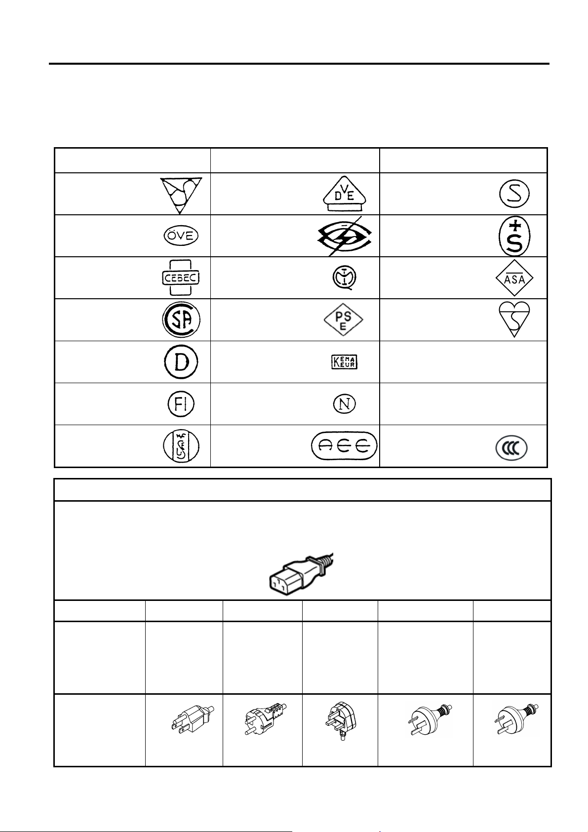
When you need to purchase a power cord
In some countries the power cord is not provided with this unit, if this is the case then please purchase an
approved one that meets the following standards or contact your authorised TOSHIBA TEC CORPORATION
representative.
(As of Oct. 2014)
Country Agency
Australia SAA Germany VDE Sweden SEMKKO
Austria OVE
Belgium CEBEC
Canada CSA
Certification
mark
Country Agency Certification mark Country Agency
Ireland NSAI
Italy IMQ
Japan METI
Switzerland SEV
UK ASTA
UK BSI
Certification
mark
Denmark DEMKO
Finland FEI
France UTE
Netherlands KEMA
Norway NEMKO
Spain AEE
U.S.A. UL
Europe HAR
China CCC
Power Cord Instruction
1. For use with 100 – 125 Vac mains power supply, please select a power cord rated Min. 125V, 10A.
2. For use with 200 – 240 Vac mains power supply, please select a power cord rated Min. 250V.
3. Please select a power cord with the length of 2m or less.
4. The power cord plug connected to the AC adapter must be able to be inserted into an ICE-320-C14 inlet. Refer to the
following figure for the shape.
Country/Region North America Europe
Power Cord
Rated (Min.)
Type
Conductor size
125V, 10A
SVT
No. 3/18AWG
250V
H05VV-F
3 x 0.75 mm
(Min.)
Plug Configuration
(locally approved
type)
Rated (Min.)
125V, 10A
250V, 10A
*1: At least, 125% of the rated current of the product.
2
United
Kin
250V
H05VV-F
3 x 0.75 mm
250V, *1
250V
AS3191 approved,
Light or Ordinary Duty type
2
3 x 0.75 mm2
250V, *1
Australia China
250V
GB5023
3 x 0.75 mm
250V, *1
2
E1- 2
Page 11
1. PRODUCT OVERVIEW ENGLISH VERSION EO1-33097
1.5 Appearance
1.5.1 Dimensions
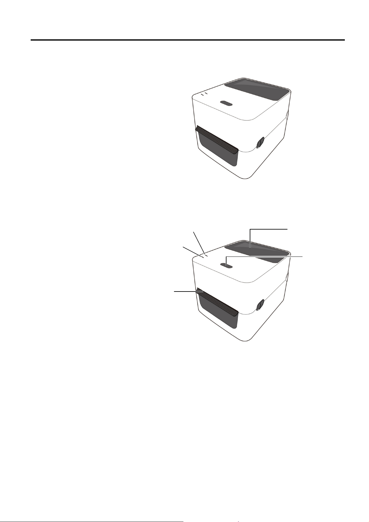
1.5.2 Front View
1.5 Appearance
The parts and units shown and named in this section are used for
descriptions in the following chapters.
W: 183.8 (7.2”) x D: 226.2 (8.9”) x H: 166.0 (6.5”)
Dimensions in mm (inches)
Media Outlet
LED 2
LED 1
Media View Window
FEED Button
E1- 3
Page 12
1. PRODUCT OVERVIEW ENGLISH VERSION EO1-33097
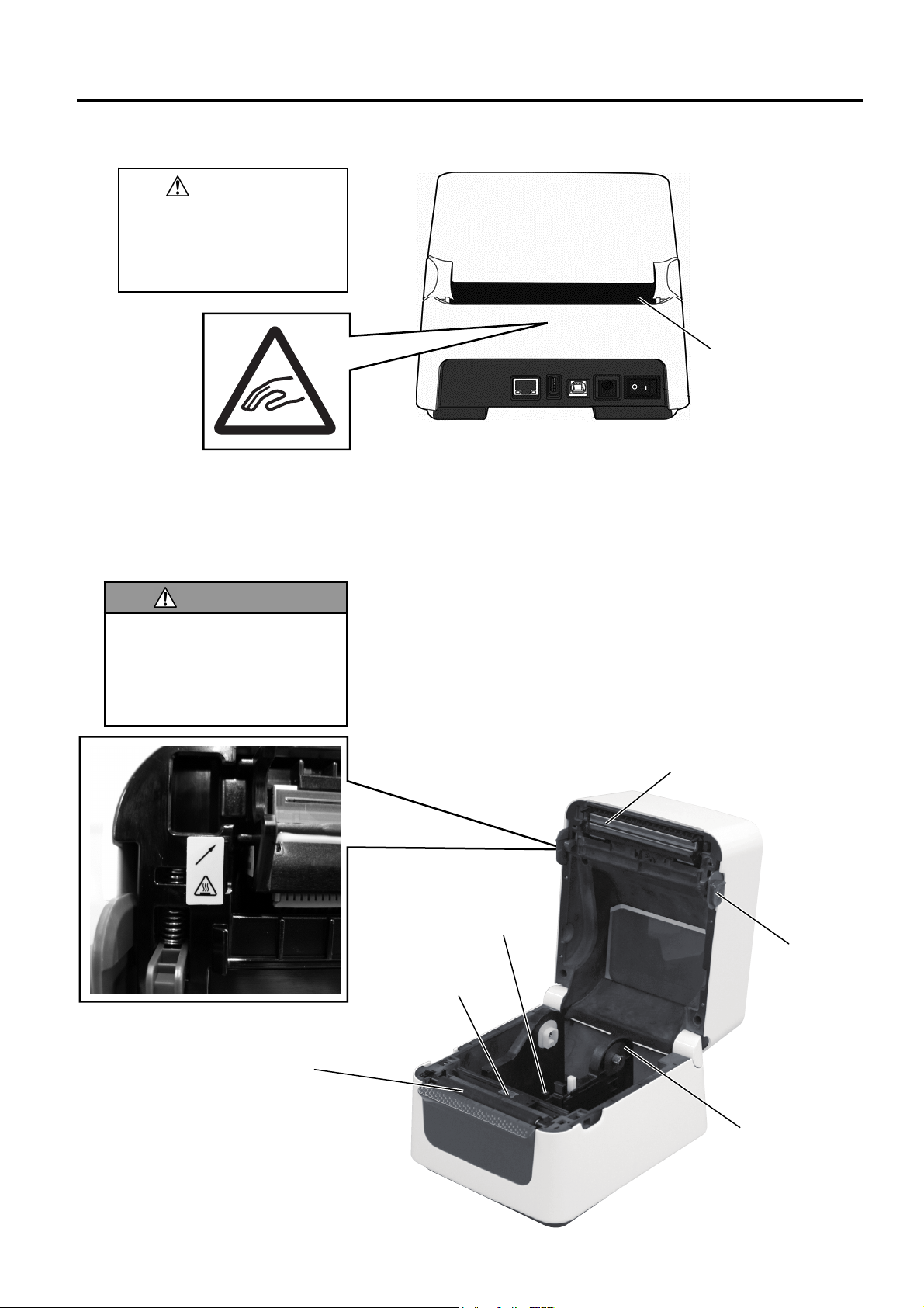
1.5.3 Rear View
To avoid injury, be careful
not to trap your fingers in the
Paper Slot while opening or
closing the Top Cover.
CAUTION!
1.5.4 Interior
The print head becomes very
hot during printing. Do not
touch the print head or touch
around it directly after printing.
By doing so you may get burnt.
WARNING!
Platen Roller
1.5 Appearance
For details of the rear view, refer to Section 2.4 Connecting the Cables
to the Printer.
Media Guides
Media Sensor
Paper Slot
Print Head
Lock Release
Portions
E1- 4
Media Roll Holders
Page 13
1. PRODUCT OVERVIEW ENGLISH VERSION EO1-33097
b
t
t
1.5.5 Button and Indicator Lamp
The [FEED] button has three functions. It can operate as a FEED,
RESTART or PAUSE button depending on current the printer state.
As a FEED
utton
As a RESTART
button
As a PAUSE
button
Pressing this button when the printer is online will cause
the media to feed forwards.
Pressing this button after removing the cause of an error
returns the printer to an online state.
Pressing this button with the printer is paused will resume
printing.
Pressing this button while the printer is printing will stop
the printing after completing the current label. The printer
is then paused.
The indicator lamps (LED1 and LED 2) light up or flash in different
colors and sequences depending on the printer status. A quick guide to
lamp statuses and their meaning is shown inside the top cover.
LED 1 LED 2 Printer Status
Unlit Unlit
Green Unli
Green S Unlit
F
Green
Green Green
Green Green
Orange Green A paper jam occurred.
Orange Red The media has ended.
Orange Red
Red Red
Red Orange
Red Green
Red Green
Red Green
Red Green
Red Orange
F: Flashes fast (0.5 sec)
M: Flashes at medium speed (1.0 sec)
S: Flashes slowly (2.0 sec)
Unli
M
F
M
F
S
M
F
M
1.5 Appearance
The power is off.
The print head block is open if the
printer power is on.
Stand-by
Printing is temporarily stopped
(paused).
Communicating with a host
Writing data to the flash or USB
memory
The Flash ROM on the CPU board or
USB memory is being initialized.
The media has ended while the print
data is being sent to the printer.
Thermal Head open error. The thermal
head has been opened during an
operation.
The print head temperature exceeded
the upper limit.
A communication error occurred.
(Only when the RS-232C is used.)
Command error
Flash ROM on the CPU board error,
or USB memory error
An erase error while formatting the
Flash ROM on the CPU board or
USB memory
Unable to save files due to
insufficient storage space on the
Flash ROM on the CPU board or
USB memory.
A paper jam occurred in the cutter unit.
(Only when the cutter unit is fitted.)
The print head is broken.
E1- 5
Page 14

2. PRINTER SETUP ENGLISH VERSION EO1-33097
2. PRINTER SETUP
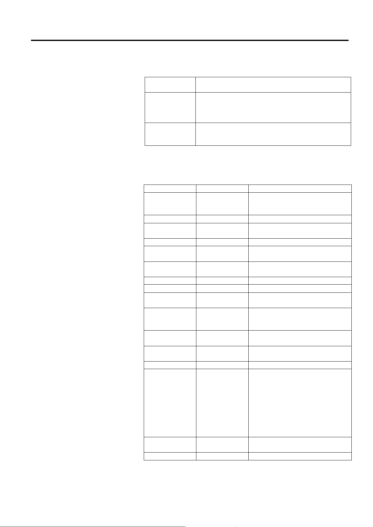
2.1 Precautions
Avoid using the printer in
the locations where it is
subjected to intense light
(e.g. direct sunlight, desk
light). Such light may affect
the sensors of the printer,
causing malfunctions.
CAUTION!
This section outlines the steps necessary to setup your printer prior to its
operation. The section includes precautions, connecting cables,
assembling accessories, loading media, and performing a test print.
To insure the best operating environment, and to assure the safety of the
operator and the equipment, please observe the following precautions.
Operate the printer on a stable, level, operating surface in a location
Keep your work environment static free. Static discharges can cause
Make sure that the printer is connected to a clean source of AC Power
Ensure that the printer is connected only to AC mains that has a
Do not operate the printer with the cover open. Be careful not to
2.1 Precautions
free from excessive humidity, high temperature, dust, vibration or
direct sunlight.
damage to delicate internal components.
and that no other high voltage devices that may cause line noise
interference are connected to the same mains.
proper ground (earth) connection.
allow fingers or articles of clothing to get caught into any of the
moving parts of the printer.
Make sure to turn off the printer power and to remove the power
adapter connector from the printer whenever working on the inside of
the printer or when cleaning the printer.
For best results, and longer printer life, use only TOSHIBA TEC
CORPORATION recommended media. (Refer to the Supply Manual.)
Store the media in accordance with the specifications.
This printer mechanism contains high voltage components; therefore
you should never remove any of the covers of the machine as you may
receive an electrical shock. Additionally, the printer contains many
delicate components that may be damaged if accessed by unauthorised
personnel.
Clean the outside of the printer with a clean dry cloth or a clean cloth
slightly dampened with a mild detergent solution.
Use caution when cleaning the thermal print head as it may become
very hot while printing. Wait until it has had time to cool before
cleaning.
Use only the TOSHIBA TEC CORPORATION recommended print
head cleaner to clean the print head.
Do not turn off the printer power or remove the power plug while the
printer is printing or while the Indicator Lamp is flashing.
The socket-outlet needs to be installed near the equipment and must
be easily accessible.
Pull out the plug from the outlet more than once a year to clean around
the prongs. Accumulating dust and dirt could cause a fire due to the
heat released by electric leakage.
E2-1
Page 15
2. PRINTER SETUP ENGLISH VERSION EO1-33097
f
2.2 Procedure before
Operation
1. To be able to communicate with
a host computer, an RS-232C,
Centronics, Ethernet, or USB
cable connection is required.
(1) RS-232C cable: 9 pins
(do not use a null modem
cable)
(2) Centronics cable: 36 pins
(3) Ethernet cable: 10/100 Base
(4) USB cable: V2.0 (Full Speed)
2. Use of the Windows Driver will
enable printing from Windows
applications.
The printer can also be controlled
with its own programming
commands. For details, please
contact your TOSHIBA TEC
CORPORATION representative.
NOTES:
2.3 Turning the Printer ON/OFF
2.3.1 Turning ON the Printer
Use the power switch to
turn the printer on/off.
Plugging or unplugging the
power cord to turn the
printer on/off may cause
fire, an electric shock, or
damage to the printer.
CAUTION!
2.2 Procedure before Operation
This section describes the steps needed to setup the printer correctly.
1. Unpack the printer and its accessories from the box.
2. Place the printer where it is to be used referring to Safety
Precautions supplied with the printer for tips on the correct use and
placement.
3. Make sure that the Power Switch is off. (Refer to Section 2.3.)
4. Connect the printer to a host computer or network using an RS-232C,
Centronics, Ethernet or USB cable. (Refer to Section 2.4.)
5. Connect the Power Adapter to the printer, and then plug the Power
Cord into a properly grounded power outlet. (Refer to Section 2.5)
6. Load the media. (Refer to Section 2.7.)
7. Adjust the position of the Feed Gap Sensor or Black Mark Sensor to
match the media being used. (Refer to Section 2.7.)
8. Install the Printer Driver on the host computer. (Refer to the Printer
Driver on the CD-ROM.)
9. Turn the Power ON. (Refer to Section 2.3.)
When the printer is connected to a host computer it is good practice to
turn the printer ON before turning on the host computer and to turn OFF
the host computer before turning off the printer.
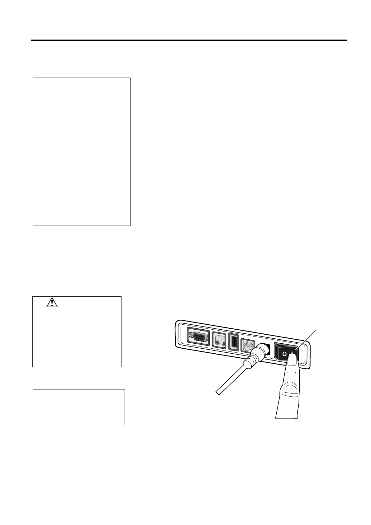
1. To turn ON the printer power, press the power switch as shown in the
diagram below. Note that ( | ) is the power ON side of the switch.
Power Switch
NOTE:
the LED 1 or 2 is illuminated in
I
red, go to Section 4.1,
Troubleshooting Guide.
2. As the printer powers on LED 1 and 2 will lite first in orange then off
and finally LED 1 should stay illuminated in green.
E2-2
Page 16

2. PRINTER SETUP ENGLISH VERSION EO1-33097
2.3.2 Turning OFF the Printer
1. Do not turn off the printer
power while the printer is
printing as this may cause
a paper jam or damage to
the printer.
2. Do not turn off the printer
power while LED 1 is
flashing as this may lead to
loss or corruption of the
data being downloaded.
CAUTION!
2.3 Turning the Printer ON/OFF
1. Before turning off the printer power switch, verify that: LED 1 is
illuminated in green (not flashing) and LED 2 is extinguished.
2. To turn OFF the printer power, press the power switch as shown in the
diagram below. Note that ( ) is the power OFF side of the switch.
Power Switch
E2-3
Page 17

2. PRINTER SETUP ENGLISH VERSION EO1-33097
2.4 Connecting Cables to the Printer
Be sure to connect the serial
or parallel cable while the
printer and the host computer
are in a powered-off state.
Failure to do this may cause
electric shocks, short-circuits,
or damage to the printer or
Host computer.
For the specifications of the
serial interface cable, refer to
APPENDIX 2, INTERFACE.
Power Switch
Power Jack
USB Interface for connecting a host
USB Interface for connecting a USB
Ethernet Interface
Serial Interface (RS-232C)*
Parallel Interface (Centronics)
CAUTION!
NOTE:
computer
memory
* Some models have no serial
interface (RS-232C).
2.4 Connecting the Cables to the Printer
This section details how to connect communication cables to the printer
from your host computer or other devices. There are four different means
of connection that can be used on the printer. These are:
An Ethernet cable connection can be used to connect to a network
or directly to your host computer’s Ethernet port.
NOTE:
▪ Use an Ethernet cable conforming to the standard.
10BASE-T: Category 3 or greater
100BASE-TX: Category 5 or greater
Cable length: Up to 100 m segment length
▪ In some environments communication errors may be caused by
electromagnetic interference on the cable. If this occurs you
may need to use a shielded cable (STP).
A USB cable connection between the printer’s USB interface port
and one of your host computer’s USB ports.
NOTE:
▪ When disconnecting the USB cable from the host computer,
follow the “Safely remove hardware” procedure on the host
computer.
▪ Use a USB cable conforming to V2.0 or greater and with a Type
B plug on one end.
A serial cable connection between the printer’s RS-232C serial
port and one of your host computer’s COM ports.
A parallel cable connection between the printer’s standard parallel
port and your host computer’s parallel port (LPT).
The diagrams below show all the possible cable connections to the
current versions of the printer.
Printer having the USB and Ethernet Interfaces
Printer having the Serial Interface (RS-232C)
Printer having the Parallel Interface (Centronics)
E2-4
Page 18

2. PRINTER SETUP ENGLISH VERSION EO1-33097
2.5 Connecting the Power Adapter and the Power Cord
1. If a power cord is not provided
with this printer, please
purchase the correct one
referring to page 1-2.
2. The EA1050B-240 AC adapter
should be exclusively used for
the B-FV4D-xxxx-QM-R
Series printer. The B-FV4Dxxxx-QM-R Series printer
must be powered by the
EA1050B-240 AC adapter.
3. The EA10681P-240 AC
adapter should be exclusively
used for the B-FV4D-xxxxQQ-R Series printer. The BFV4D-xxxx-QQ-R Series
printer must be powered by
the EA10681P-240 AC
adapter.
NOTES:
2.5 Connecting the Power Adapter and the Power Cord
1. Make sure that the printer power switch is in the OFF (O) position.
2. Insert the Power Cord into the inlet of the Power Adapter.
Power Cord
Power Adapter
3. Insert the Power Adapter connector into the Power Jack on the rear of
the printer.
Power Jack
Power Adapter Connector
WARNING!
The areas indicated by the ellipse have sharp edges.
To avoid injury, be careful not to touch them when handling the
printer.
E2-5
Page 19

2. PRINTER SETUP ENGLISH VERSION EO1-33097
2.6 Opening/Closing the Top Cover
WARNING!
To avoid injury, be careful
not to trap your fingers while
opening or closing the cover.
CAUTION!
1. Be careful not to touch the
Print Head Element when
opening the Top Cover.
Failure to do this may
cause missing dots by
static electricity or other
print quality problems.
2. Do not cover the Cover
Open Sensor with your
finger, hand, etc. Doing so
may cause the sensor to
wrongly detect a cover
close state.
NOTE:
Be sure to close the Top Cover
completely. Failure to do this
may affect the print quality.
Top Cover
2.6 Opening/Closing the Top Cover
When opening or closing the Top Cover, please be sure to follow the
instructions below.
To open the Top Cover:
1. Open the Top Cover while pulling the Lock Release Portions as
indicated by the arrows.
Lock Release Portion
To close the Top Cover:
1. Close the Top Cover.
E2-6
Page 20

2. PRINTER SETUP ENGLISH VERSION EO1-33097
2.7 Loading the Media
1. Do not touch any moving
parts. To reduce the risk
of fingers, jewellery,
clothing, etc. being drawn
into the mechanism, be
sure to load the media
only once the printer has
completely stopped
moving.
2. To avoid injury, be careful
not to trap your fingers
while opening or closing
the Top Cover.
Be careful not to touch the
Print Head Elements when
opening the Top Cover. Doing
this may cause damage to
some of the dots through
static discharge or other print
quality problems.
WARNING!
CAUTION!
2.7 Loading the Media
This section describes how to load the media in the printer. This printer
accepts label rolls, tag rolls, and fanfold paper stocks. Please use
TOSHIBA TEC CORPORATION approved media.
NOTES:
1. Please perform a media sensor calibration whenever you change the
media type.
2. The size of the media which can be loaded inside the printer is as
follows:
Outer roll diameter: Max. 127mm (5”)
Inner core diameter: 25.4 (1”) mm or 38.1 mm (1.5”)
When the outer roll diameter exceeds 127 mm or the inner core
diameter exceeds 38.1 mm, an optional External Media Stand is
required. For details, refer to the
FV904-PH-QM-R External Media Stand
At factory shipment, the core holder size is set for 1.5” on the Media
Roll Holders. If you want to use 1” core media, detach the core
holders by loosening the thumb screws, reverse the core holders then
re-attach them with the thumb screws to the Media Roll Holders as
shown below.
Installation Manual for the B-
.
Core Holder
3. Media rolls can be wound inside or wound outside. (See the diagram
below.) Both types of media roll should be loaded so that the print
side faces up.
Outside wound Inside wound
E2-7
Page 21

2. PRINTER SETUP ENGLISH VERSION EO1-33097
r
2.7 Loading the Media
(Cont.)
1. Make sure that the print side
2. Cut the leading edge of the
NOTE: Media path
For the outside- wound media
Feed Gap Sensor
Platen
For the inside- wound media
Feed Gap Sensor
Platen
faces up.
media straight with scissors.
Black mark sensor
Black mark sensor
NOTES:
2.7 Loading the Media
1. Open the Top Cover while pulling the Lock Release Portions as
indicated by the arrows.
Top Cover
Lock Release Portion
2. Open the Media Roll Holders by pressing the Holder Lock Lever and
slide them outward. Place the media roll between the holders ensuring
that print side is facing up, then using Holder Lock Lever slide the
Media Roll Holders to clamp the media roll tightly.
Holder Lock Leve
E2-8
Page 22
2. PRINTER SETUP ENGLISH VERSION EO1-33097
2.7 Loading the Media
(Cont.)
2.7 Loading the Media
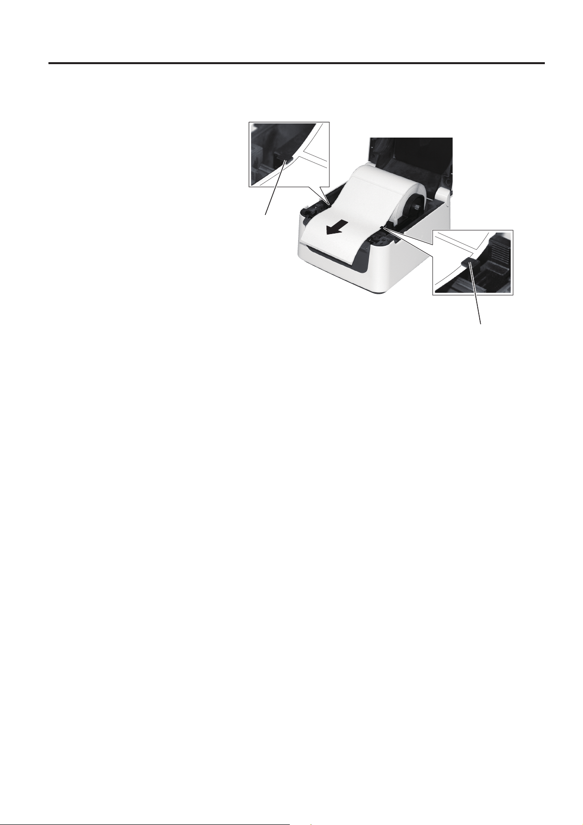
3.
Pass the media through the Media Guides. Pull the media until it reaches
the front of the printer.
Media Guide
Media Guide
E2-9
Page 23

2. PRINTER SETUP ENGLISH VERSION EO1-33097
f
2.7 Loading the Media
(Cont.)
1. The sensor type used in the last
print job is selected by default.
To change the sensor type, refer
to Section 2.8.1 Media Sensor
Calibration.
2. The Feed Gap Sensor is
positioned 6.35 mm right from
the media centre.
3. The Black Mark Sensor is
movable over the range of the
media width.
Black Mark Sensor is movable
in the full range.
Be careful not to squeeze the
media with the Media Guides.
Doing so bends the media,
which can cause a paper jam or
eed failure.
NOTES:
Feed Gap Sensor
6.35mm
NOTE:
2.7 Loading the Media
4. Check and adjust the media sensor position and select the sensor type
to be used. (Refer to Section 2.8.1.)
This printer has a Black Mark Sensor which can detect black marks
printed on the reverse side of the media, and a Feed Gap Sensor which
detects inter-label gaps. As the Feed Gap Sensor position is fixed, it is not
necessary to adjust it. When using the Black Mark Sensor, align it with
the centre of the black mark on the media. Failure to do this will disable
the detection of printed black marks, resulting in an error.
Black Mark Sensor
E2-10
Page 24

2. PRINTER SETUP ENGLISH VERSION EO1-33097
2.7 Loading the Media
(Cont.)
2.7 Loading the Media
5. Close the Top Cover, then press the [FEED] button to check the media
feeds correctly.
FEED Button
CAUTION!
To separate the printed
media from the printer in
batch mode, be sure to tear
the media off at the Media
Outlet or cut the media past
the Strip Plate. If you tear
the media off at the Print
Head by mistake, be sure to
feed one label (10 mm or
more) with the FEED Button
prior to the next issue.
Failure to do this may cause
a paper jam.
There are three issue modes available for this printer.
Batch mode:
In the batch mode, the media is continuously printed and fed until the
number of prints specified in the issue command has been printed.
E2-11
Page 25

2. PRINTER SETUP ENGLISH VERSION EO1-33097
2.7 Loading the Media
(Cont.)
1. When printing labels without
removing them from the backing
paper, it is not necessary to pass
the media through the Strip Block.
2. When the media is correctly set,
the backing paper should be
pinched between the Platen and
the Strip Feed Roller as shown
below.
Strip Plate
Label
Strip Feed Roller
Backing Paper
When opening the Peel-off Unit
for loading the media, be
careful not to drop metal or
other foreign objects, such as a
paper clip into the module, as
this may cause a malfunction of
the printer.
NOTES:
Platen
CAUTION!
2.7 Loading the Media
Strip mode (Option):
When printing in strip mode, labels are automatically removed from the
backing paper as each label is printed.
How to set the media
When issuing labels in the strip mode, set the label in the following
procedure:
1. Load the media as described on the previous pages.
2. Open the Peel-off Unit by pulling it out.
Peel-off Unit
3. Remove enough labels from the leading edge of the media to leave 20
cm of backing paper free, and insert the top edge of the backing paper
into the media slot in the Peel-off Unit as shown below.
4. Close the Peel-off Unit and Top Cover.
E2-12
Page 26

2. PRINTER SETUP ENGLISH VERSION EO1-33097
2.7 Loading the Media
(Cont.)
HAZARDOUS MOVING PARTS
KEEP FINGERS AND OTHER
BODY PARTS AWAY
The cutter is sharp, so care must
be taken not to injure yourself
when handling the cutter.
WARNING!
1. Be sure to cut only the backing
paper of the label. Cutting
labels will cause glue to stick to
the cutter blades which may
affect the cutter quality and
shorten the cutter life.
2. Use of tag paper which
thickness exceeds the
maximum specified value may
affect the cutter life.
When placing fanfold paper
stock at the rear of the printer,
care should be taken of the
following points.
1. Face the print surface up.
2. The fanfold paper stock is
parallel to the fanfold paper
slot.
3. The interface and power
cables do not interfere with
the feeding of the fanfold
paper.
CAUTION!
NOTE:
2.7 Loading the Media
Cut mode (Option):
When a Cutter is fitted, the media can be automatically cut. When
loading the media as described on the previous pages, insert the leading
edge of the media through the Media Outlet of the Cutter Cover while
pulling the media through the printer.
Cutter Cover
Media Outlet
How to Load Fanfold Paper Stock
1. Place the fanfold paper stock at the rear of the printer, insert the
leading edge of the paper into the Fanfold Paper Slot.
Fanfold Paper Stock
Fanfold Paper Slot
2. Refer to the previous pages to feed the fanfold paper through the
printer until it extends past the media outlet.
E2-13
Page 27

2. PRINTER SETUP ENGLISH VERSION EO1-33097
2.7 Loading the Media
(Cont.)
External Media
Stand (Option)
Fanfold Paper Slot
2.7 Loading the Media
When the media roll has an outside diameter exceeding 127 mm (5”) or
the inner core diameter is 76.2 mm (3”), the optional External Media
Stand is needed.
Remark:
Pictures below is the thermal transfer printing model of the B-FV4 series.
1. Fit the feet on the bottom of the printer as shown below.
2. Insert the Media Shaft into the core of the media roll.
3. Place it into the slots on the External Media Stand.
4. Pull the media forward and insert the leading edge into the Fanfold
Paper Slot.
Media Shaft (Option)
5. Refer to the previous pages to complete the media loading.
E2-14
Page 28

2. PRINTER SETUP ENGLISH VERSION EO1-33097
2.8 Media Sensor Calibration, Self Print Test, and Dump Mode Utilities
2.8.1 Media Sensor
Calibration
The selected sensor used in the last
print job is remembered and always
used. The factory default sensor is
the Feed Gap Sensor.
NOTE:
2.8 Media Sensor Calibration, Self Print Test, and Dump Mode Utilities
These utilities are used to calibrate the sensitivity of the Feed Gap/Black
Mark Sensor, Print out a test with details of the printer settings and set
the printer into Dump mode.
When changing from one type of media to another, it is necessary to
calibrate the media sensors.
1. Turn off the printer, make sure the media is correctly loaded, and
close the Top Cover.
Note: Do not place a pre-printed area above the media sensor, as
doing so disables correct sensor calibration.
2. Press and hold the [FEED] Button while turning on the printer.
3. Both status lights (LED 1 and LED 2) will light up in the following
order:
Orange Green Other colour sequences
4. Release the [FEED] button when LED 1 and LED 2 light to match the
sensor you want to calibrate.
Feed Gap (Transmissive) Sensor: LED 1 green, LED 2 in red.
Black Mark (Reflective) Sensor: LED 1 green, LED 2 orange.
5. Press the [FEED] button.
The printer will feed the media and perform the sensor calibration.
6. To return to Online operation, turn the printer off, then on again.
E2-15
Page 29

2. PRINTER SETUP ENGLISH VERSION EO1-33097
-
FV4D-G P
2.8.2 Self Print Test and
Dump Mode
The following commands will
have no effect the test print. D,
AX, XS, Z2;1, Z2;2 (only the AY
command will)
NOTE:
2.8 Media Sensor Calibration, Self Print Test, and Dump Mode Utilities
1. Turn off the printer power and install a full width media roll
(104mm/4inch) in the printer.
Press and hold the [FEED] Button while turning on the printer. The
2.
status lamps (LED 1 and LED 2) will light up in the following order:
Orange Green Other colour sequences
3. Release the [FEED] Button when LED 1 lights in orange and LED 2
lights in green.
4. Press the [FEED] button.
5. The printer prints the self print test, and then enters Dump Mode.
6. To return to Online operation, turn the printer off, then on again.
Print test label sample
B
PROGRAM VERSION 05MAY2014B-FV4 V1.1J
TPCL VERSION 28APR2014 V1.0K
CG VERSION 27FEB2014 V1.0
CHINESE VERSION 27FEB2014 V1.0
CODEPAGE VERSION 27FEB2014 V1.0
BOOT VERSION V1.1C
KERNEL FONT VERSION 1.0.03
WLAN MODULE [Installed]
BLUETOOTH MODULE [Installed]
[PARAMETERS]
HW DETECT [0000000000000000]
TONE ADJUST(T) [---]
TONE ADJUST(D) [+00]
FEED ADJUST [+0.0mm]
CUT ADJUST [+0.0mm]
BACKFEED ADJUST [+0.0mm]
X-COORD. ADJUST [+0.0mm]
CODEPAGE [PC-850]
ZERO SLASH [0]
FEED KEY [FEED]
EURO CODE [B0]
CONTROL CODE [AUTO]
MAXI CODE SPEC. [TYPE 1]
SENSOR SELECT [Transmissive]
PRINT SPEED [5ips]
FORWARD WAIT [ON]
AUTO CALIB. [OFF]
MULTI LABEL [OFF]
AUTO THP CHK [OFF]
BASIC [OFF]
Reserved item1
Reserved item2
FLASH ROM [16MB]
SDRAM [32MB]
USB SERIAL NUM. [000000000001]
[INFORMATION]
INFORMATION [B-FV4D-GS12-QM-R]
[2303A000006]
TOTAL FEED1 [0.00km]
TOTAL FEED2 [00000cm]
[0000.0inch]
TOTAL PRINT [0.00km]
TOTAL CUT [0]
[RS-232C]
BAUD RATE [9600]
BIT [8]
STOP BIT [1]
PARITY [None]
FLOW [XON/XOFF]
RINTER INFO.
E2-16
Page 30

2. PRINTER SETUP ENGLISH VERSION EO1-33097
2.8.2 Self Print Test and
Dump Mode (Cont.)
Printed when the Wireless LAN
interface option is installed.
Printed when the Bluetooth
interface option is installed.
2.8 Media Sensor Calibration, Self Print Test, and Dump Mode Utilities
[LAN]
IP ADDRESS [192.168.010.020]
SUBNET MASK [255.255.255.000]
GATEWAY [000.000.000.000]
MAC ADDRESS [ab-cd-ef-01-23-45]
DHCP [OFF]
DHCP CLIENT ID [FFFFFFFFFFFFFFFF]
[FFFFFFFFFFFFFFFF]
DHCP HOST NAME [ ]
[ ]
SOCKET COMM. [ON]
SOCKET PORT [8000]
[WLAN]
WLAN IP ADDRESS [192.168.10.200]
WLAN SUBNET MASK [255.255.255.000]
WLAN GATEWAY [0.0.0.0]
WLAN MAC ADRESS [00-80-92-4F-44-B]
WLAN DHCP [OFF]
WLAN DHCP HOSTNAME [00-80-92-4F-44-B]
[ E]
WLAN SOKET PORT [9100]
ESS ID [TOSHIBA_B-FV4]
[ ]
WLAN MODE [Infrastructure]
NETWORK AUTH. [OPEN]
WEP [OFF]
WEP DEFAULT KEY [1]
WPA ENCRYPTION [DISABLE]
EAP METHOD [DISABLE]
REGION CODE [USA]
CHANNEL [AUTO]
[BLUETOOTH]
DEVICE NICKNAME [B-FV4]
INQUIRY [EVERY]
ADDRESS
* The barcode printed here displays a
Bluetooth address.
Barcode
The test print content are different based on the emulation mode. The list
below is for TPCL mode.
PROGRAM VERSION ------------------------
TPCL VERSION --------------------------------
CG VERSION -----------------------------------
CHINESE VERSION--------------------------- Firmware version
CODEPAGE VERSION -----------------------
BOOT VERSION -------------------------------
KERNEL FONT VERSION -------------------
WLAN MODULE ------------------------------ WLAN module installation flag
BLUETOOTH MODULE --------------------- Bluetooth module installation flag
HW DETECT ------------------------------------ Hardware detection flag
TONE ADJUST(T) ----------------------------- Reserved parameter
TONE ADJUST(D) ----------------------------- Print tone fine adjustment value
FEED ADJUST---------------------------------- Print position fine adjustment value
CUT ADJUST ----------------------------------- Cut position fine adjustment value
E2-17
Page 31

2. PRINTER SETUP ENGLISH VERSION EO1-33097
2.8 Media Sensor Calibration, Self Print Test, and Dump Mode Utilities
BACKFEED ADJUST ------------------------- Back feed amount fine adjustment value
X-COORD. ADJUST --------------------------- X-coordinate fine adjustment value
CODEPAGE ------------------------------------- Character code selection
ZERO SLASH ----------------------------------- Font “0” selection
FEED KEY--------------------------------------- [FEED] key function setting
EURO CODE ------------------------------------ Euro code setting
CONTROL CODE ------------------------------ Control code type
MAXI CODE SPEC. --------------------------- Maxicode specification setting
SENSOR SELECT ------------------------------ Sensor type
PRINT SPEED ---------------------------------- Print Speed
FORWARD WAIT ----------------------------- Forward feed standby after issue
AUTO CALIB. ---------------------------------- Automatic calibration setting
MULTI LABEL --------------------------------- Multi label setting
AUTO TPH CHECK --------------------------- Automatic print head check for broken dots
setting
BASIC -------------------------------------------- Basic interpreter setting
Reserved item1 ---------------------------------- Reserved parameter
Reserved item2 ----------------------------------
FLASH ROM ------------------------------------ Flash ROM Capacity
SDRAM ------------------------------------------ SDRAM Capacity
USB SERIAL NUM. --------------------------- USB serial number
INFORMATION -------------------------------- Printer model name and serial number.
TOTAL FEED1 --------------------------------- Total feed distance (condition1)
TOTAL FEED2 --------------------------------- Total feed distance (condition2)
TOTAL PRINT ---------------------------------- Total Print distance
TOTAL CUT ------------------------------------ Total Cut Count
[RS-232C] ---------------------------------------- RS-232C setting value
(BAUD RATE, BIT, STOP BIT, PARITY, FLOW)
[LAN] --------------------------------------------- Network setting values
(IP ADDRESS, SUBNET MASK, GATEWAY, MAC ADDRESS, DHCP, DHCP
CLIENT ID, SOCKET COMM., SOCKET PORT)
[WLAN] ------------------------------------------ Network setting values
(WLAN IP ADDRESS, WLAN SUBNET MASK, WLAN GATEWAY, WLAN MAC
ADRESS, WLAN DHCP, WLAN DHCP HOSTNAME, WLAN SOKET PORT, ESS
ID, WLAN MODE, NETWORK AUTH., WEP, WEP DEFAULT KEY, WPA
ENCRYPTION, EAP METHOD, REGION CODE, CHANNEL)
[BLUETOOTH] --------------------------------- Network setting values
(DEVICE NICKNAME, INQUIRY, ADDRESS
*
ADDRESS (Bluetooth address) is displayed with a barcode.
*
)
E2-18
Page 32
3. MAINTENANCE ENGLISH VERSION EO1-33097
3. MAINTENANCE
1. Be sure to turn OFF the
2. To avoid injury, be careful
3. Be careful when handling
4. Do not pour water directly
3.1 Cleaning
3.1.1 Print Head
1. Do not allow any hard
objects to touch the print
head or platen, as this may
cause damage to them.
2. Do not use any volatile
solvents including thinner
and benzene, as this may
cause discoloration of the
cover, print failure, or
breakdown of the printer.
3. Do not touch the print head
element with bare hands,
as static may damage the
print head.
WARNING!
power before performing
any maintenance. Failure
to do this may cause an
electric shock.
not to trap your fingers
while opening or closing
the cover.
the print head as it
becomes very hot during
printing. Allow it to cool
before performing any
maintenance.
onto the printer.
CAUTION!
3.1 Cleaning
This chapter details the routine maintenance procedures.
To ensure the continuous high quality operation of your printer, you
should regularly perform these maintenance routines. Where the printer is
intensively used (high throughput) it should be done on a daily basis.
Where the printer is not intensively used (low throughput) it should be
done on a weekly basis.
To maintain the printer performance and print quality, please clean the
printer regularly, or whenever the media is replaced.
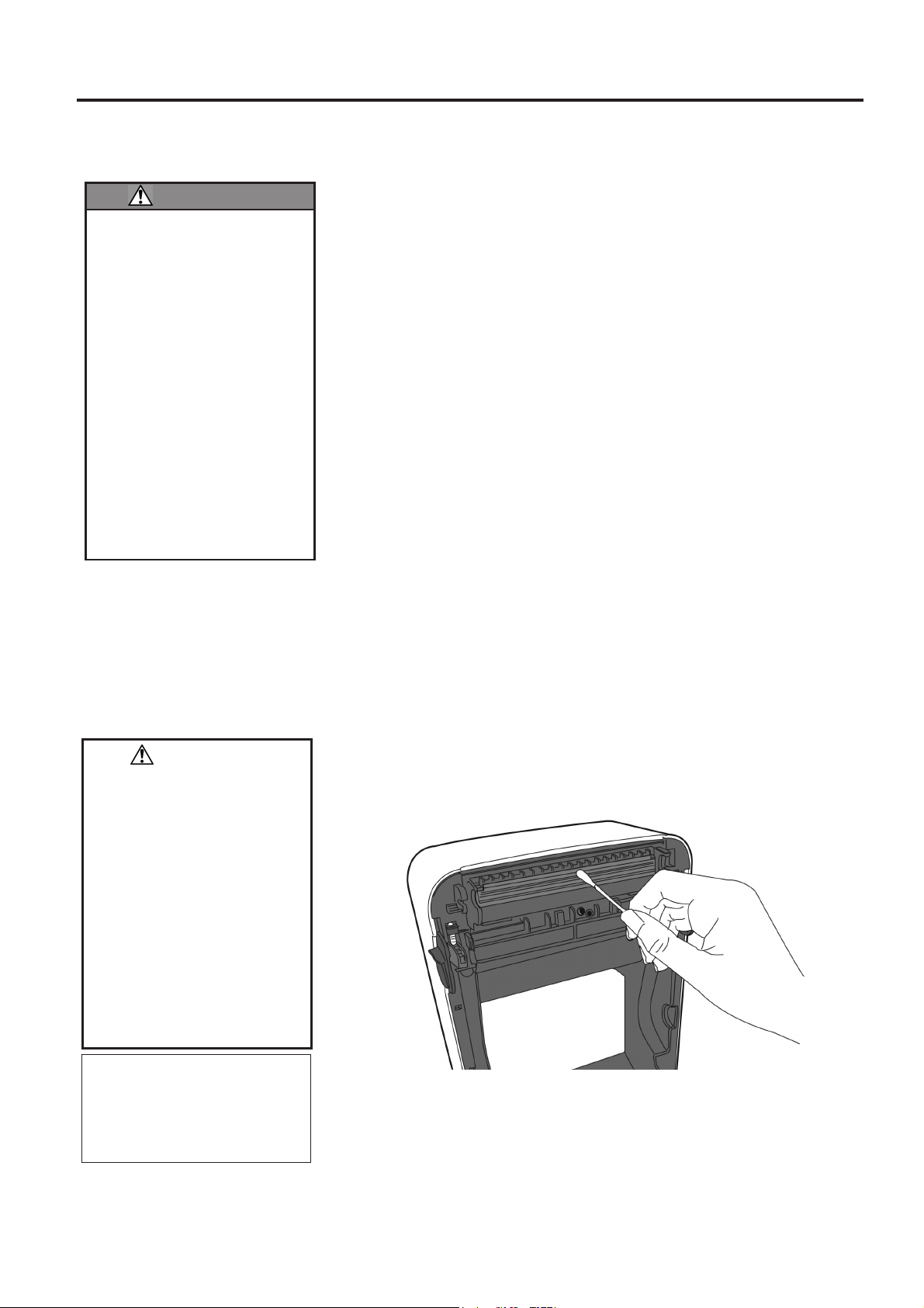
1. Turn the power off.
2. Open the Top Cover.
3. Clean the Print Head Element with a Print Head Cleaner, cotton swab
or soft cloth slightly moistened with ethyl alcohol.
NOTE:
Print Head Cleaners can be
purchased from your authorised
TOSHIBA TEC CORPORATION
service representative.
E3- 1
Page 33

3. MAINTENANCE ENGLISH VERSION EO1-33097
3.1.2 Sensors
3.1.3 Platen Roller
3.1 Cleaning
1. Wipe the media sensors with a soft cloth or a cotton swab lightly
moistened with absolute (pure) ethyl alcohol.
2. To remove dust or paper particles wipe the media sensors with a dry
soft cloth.
Wipe the platen roller with a soft cloth moistened with absolute (pure) ethyl
alcohol.
E3- 2
Page 34

3. MAINTENANCE ENGLISH VERSION EO1-33097
3.1.4 Media Housing
3.1 Cleaning
Wipe the media housing with a dry soft cloth. Wipe off dirt with a soft cloth
slightly moistened with mild detergent solution.
E3- 3
Page 35

3. MAINTENANCE ENGLISH VERSION EO1-33097
3.2 Care/Handling of the Media
CAUTION!
Be sure to carefully review and
understand the Supply
Manual. Use only media
which meet specified
requirements. Use of nonspecified media may shorten
the head life and result in
problems with barcode
readability or print quality. All
media should be handled with
care to avoid any damage to
the media, or printer. Read
the guideline in this section
carefully.
3.2 Care/Handling of the Media and Ribbon
Do not store media for longer than the manufacturer’s recommended
shelf life
Store media rolls on the flat end. Do not store them on the curved
sides as this might flatten that side causing erratic media advance and
poor print quality.
Store the media in plastic bags and always reseal after opening.
Unprotected media can get dirty and the extra abrasion from the dust
and dirt particles will shorten the print head life.
Store the media in a cool, dry place. Avoid areas where they would be
exposed to direct sunlight, high temperature, high humidity, dust or
gas.
The thermal paper used for direct thermal printing must not have
specifications which exceed Na
ppm.
Some ink used on pre-printed media may contain ingredients which
shorten the print head’s product life. Do not use labels pre-printed
with ink which contain hard substances such as carbonic calcium
(CaCO
For further information, please contact your local distributor or your
media manufacturer.
) and kaolin (Al2O3, 2SiO2, 2H2O).
3
+
800 ppm, K+ 250 ppm and Cl- 500
E3- 4
Page 36

4. TROUBLESHOOTING ENGLISH VERSION EO1-33097
4.1 Troubleshooting Guide
4. TROUBLESHOOTING
If a problem cannot be solved by taking actions described in this chapter, do not attempt to repair the
printer. Turn off and unplug the printer. Then contact an authorised TOSHIBA TEC
CORPORATION service representative for assistance.
4.1 Troubleshooting Guide
Symptom Cause Solutions
The power lamp of the
Power Adapter does not
light up though the power
cord is plugged in an AC
outlet.
LED 1 does not light up in
green when the power
switch is turned on though
the power lamp of the
Power Adapter is lit.
Media is not issued. The media is not loaded correctly. Reload the media correctly.
Nothing is printed. The media loaded is not direct
Poor print TOSHIBA TEC
Missing dots The print head is dirty.
The power cord is not connected
to the Power Adapter.
There is a power failure or the
power is not being supplied to the
AC outlet.
The fuse of the building has
blown or the circuit breaker has
tripped.
The Power Adapter Connector is
disconnected from the Power
Jack.
The interface cable is not
connected correctly.
The media sensor is dirty. Clean the media sensor.
thermal media though direct
thermal mode is selected.
The media is not correctly loaded.
Print data is not sent from the host
computer.
CORPORATION approved media
is not used.
The print head is dirty.
Some of the print head elements
are broken.
WARNING!
Disconnect the power cord from the AC outlet,
connect the power cord to the Power Adapter,
then connect it to the AC outlet.
( Section 2.5)
Test the AC outlet with a power cord from
another electric appliance.
If power is not being supplied, consult an
electrician or your Electricity supplier.
Check the fuse or circuit breaker.
Disconnect the power cord from the AC outlet,
insert the Power Adapter Connector into the
Power Jack, then connect the power cord to the
AC outlet. ( Section 2.5)
( Section 2.7)
Connect the interface cable again.
( Section 2.4)
( Section 3.1.2)
Load a thermal paper roll.
( Section 2.7)
Reload the media correctly.
( Section 2.7)
Send the print data.
Replace the media with an approved one.
Clean the print head. ( Section 3.1.1)
Clean the print head. ( Section 3.1.1)
When missing dots affect the printout, turn off
the printer and contact the nearest TOSHIBA
TEC CORPORATION representative to ask for
the replacement of the print head.
E4-1
Page 37

4. TROUBLESHOOTING ENGLISH VERSION EO1-33097
4.2 Status Lamp
Symptom Cause Solutions
Labels are not correctly
separated from the backing
paper. (When the optional
Peel-off unit is fitted.)
TOSHIBA TEC
CORPORATION approved media
is not used.
The labels have been loaded
Replace the media with an approved one.
Load the label correctly. ( Section 2.7)
incorrectly.
The media is not cut
cleanly. (When the optional
cutter unit is fitted.)
The cuter blade has reached the
end of its useful life.
Turn off the printer and contact the nearest
TOSHIBA TEC CORPORATION
representative to ask for the replacement of the
cutter unit.
The Wireless LAN
communication error
occurs immediately after
turning on the printer.
It takes approx. 10 seconds to
enable the Wireless LAN
communication after the Status
Lamp shows a stand-by state.
Turn on the printer, and wait more than 10
seconds after the Status Lamp shows a stand-by
state, then start the communication.
4.2 Status Lamp
LED 1 LED 2 Cause Solutions
Green Unlit Stand-by Normal
Green F
Green S
Red
Red
Orange
Orange
Red
Red
Red
Unlit
Flashing speed of the LED
Symbol Status Flashing interval
S
M
F
Flashing slowly 2.0 sec.
Flashing at medium speed 1.0 sec.
Flashing fast 0.5 sec.
Unlit
Unlit
Orange F
Green A communication error
Red
Green
Red M
Green
Orange M
Unlit
Communicating with a host Normal
Printing is temporarily stopped
Press the [FEED] Button. Printing is resumed.
(paused.)
The print head temperature
exceeded the upper limit.
Stop printing and allow the print head to cool
until LED 1 lights in green. If LED 1 does not
light in green or this problem occurs frequently,
contact the nearest TOSHIBA TEC
CORPORATION representative.
Press the [FEED] Button to restart the printer or
occurred. (Only when the RS232C is used.)
Turn off the power and then back on. If this
problem frequently occurs, turn off the printer
and contact the nearest TOSHIBA TEC
CORPORATION representative.
The media has ended. Load a new media roll, then press the [FEED]
Button. ( Section 2.7)
A paper jam occurred. Remove the jammed media, then reload the
media correctly and press the [FEED] Button.
( Section 4.3)
An issue or feed was
attempted with the print block
Close the print block correctly, then press the
[FEED] button. Printing will resume.
opened.
A paper jam occurred in the
F
cutter unit. (Only when the
cutter unit is fitted.)
Remove the jammed media, then reload the
media correctly and press the [FEED] Button.
( Section 4.3)
The print head is broken. Turn off the power switch and contact the
nearest TOSHIBA TEC CORPORATION
representative.
The power is off.
The print head block is open if
Turn the power on.
Close the print block correctly.
the printer power is on.
E4-2
Page 38

4. TROUBLESHOOTING ENGLISH VERSION EO1-33097
4.3 Removing Jammed Media
4.3 Removing Jammed Media
This section describes in detail how to remove jammed media from the printer.
CAUTION!
Do not use any tool that may damage the print head.
1. Turn the power off.
2. Open the Top Cover and open the print head block.
3. Remove the media roll.
4. Remove the jammed media from the printer. DO NOT USE any sharp implements or tools as these could
damage the printer.
If a paper jam has occurred inside the Cutter Unit, follow the steps below to remove the paper.
1) Turn the power off.
2) Tilt the printer to the left.
3) Remove the jammed paper by forcibly rotating the cutter motor using a cross/philips screwdriver.
Remark:
The picture above is the thermal transfer printing model of the B-FV4 series.
5. Clean the Print Head and Platen, then remove any further dust or foreign substances.
6. Load the media again, and close the Top Cover.
Cutter Motor
E4-3
Page 39

APPENDIX 1 SPECIFICATIONS ENGLISH VERSION EO1-33097
APPENDIX 1 SPECIFICATIONS
Appendix 1 describes the printer specifications and supplies for use on the B-FV4D printer.
A1.1 Printer
The following are the printer specifications.
Item B-FV4D-GS Series
Supply voltage
Power consumption
During a print job
During standby
Operating temperature range
Storage temperature range
Relative humidity
Humidity for storage
Resolution
Printing method
Issue mode
Printing speed
In the batch/cut mode
In the strip mode
Available media width
(including backing paper)
Effective print width (max.)
Max. print ratio
Dimension (W D H)
Weight
Available barcode types
Available two-dimensional code
Available composite symbol
Available font
Rotations
Standard interface
Option interface
NOTES:
Data Matrix
PDF417
QR Code is a trademark of DENSO CORPORATION.
Maxi Code is a trademark of United Parcel Service of America, Inc., U.S.
TM
is a trademark of International Data Matrix Inc., U.S.
TM
is a trademark of Symbol Technologies Inc., US.
Bluetooth® is a registered trademark owned by Bluetooth SIG, Inc.
AC100 to 240V, 50/60 Hz (External Power Adapter)
100 to 120V: 1.0 A, 60 W maximum, 200 to 240V: 0.6 A, 59 W maximum
100 to 120V: 0.12A, 3.7 W maximum, 200 to 240V: 0.07 A, 3.8 W maximum
5C to 40C (41F to 104F)
-20C to 60C(-4F to 140F)
25% to 85% RH (no condensation)
10% to 90% RH (no condensation)
203 dpi (8 dots/mm)
Direct thermal
Batch, Strip (option), Cut (option)
50.8 mm/sec. (2”/sec.), 76.2 mm/sec. (3”/sec.), 101.6 mm/sec. (4”/sec.),
127 mm/sec. (5”/sec.), 152.4 mm/sec. (6”/sec.)
50.8 mm/sec. (2”/sec.), 76.2 mm/sec. (3”/sec.)
25.4 mm (1.0”) to 118 mm (4.6”)
108.0 mm (4.25”)
Average 15%
183.8 mm x 226.2 mm x 166.0 mm (7.2” x 8.9” x 6.5”)
1.76 kg (3.8 lb) (Excluding media)
EAN8/13, EAN8/13 add on 2&5, UPC-A, UPC-E, UPC-A add on 2&5, UPC-E
add on 2&5, CODE39, CODE93, CODE128, GS1-128 (UCC/EAN128), NW7,
MSI, Industrial 2 of 5, ITF, RM4SCC, KIX-Code, POSTNET, USPS Intelligent
mail barcode, GS1 DataBar
Data matrix, PDF417, QR Code, Maxi Code, Micro PDF417
GS1-128 Composite (CC-A/CC-B/CC-C)
Times Roman (6 sizes), Helvetica (6 sizes), Presentation (1 size), Letter Gothic
(1 size), Courier (2 sizes), Prestige Elite (2 sizes), OCR-A (1 type), OCR-B (1
type), Simplified Chinese (1 size)
0, 90, 180, 270
USB 2.0 full speed
Ethernet interface (10/100 Base)
Serial interface (RS-232C) (factory option)
Parallel interface (Centronics) (factory option)
Wireless LAN interface (IEEE802.11b/g/n)
Bluetooth interface (Ver.2.1)
A1.1 Printer
EA1-1
Page 40

APPENDIX 1 SPECIFICATIONS ENGLISH VERSION EO1-33097
Item B-FV4D-TS Series
Supply voltage
Power consumption
During a print job
During standby
Operating temperature range
Storage temperature range
Relative humidity
Humidity for storage
Resolution
Printing method
Issue mode
Printing speed
In the batch/cut mode
In the strip mode
Available media width
(including backing paper)
Effective print width (max.)
Max. print ratio
Dimension (W D H)
Weight
Available barcode types
Available composite symbol
Available two-dimensional code
Available font
Rotations
Standard interface
Option interface
NOTES:
Data Matrix
PDF417
QR Code is a trademark of DENSO CORPORATION.
Maxi Code is a trademark of United Parcel Service of America, Inc., U.S.
Bluetooth® is a registered trademark owned by Bluetooth SIG, Inc.
TM
is a trademark of International Data Matrix Inc., U.S.
TM
is a trademark of Symbol Technologies Inc., US.
AC100 to 240V, 50/60 Hz (External Power Adapter)
100 to 120V: 1.0 A, 60 W maximum, 200 to 240V: 0.6 A, 59 W maximum
100 to 120V: 0.12A, 3.7 W maximum, 200 to 240V: 0.07 A, 3.8 W maximum
5C to 40C (41F to 104F)
-20C to 60C(-4F to 140F)
25% to 85% RH (no condensation)
10% to 90% RH (no condensation)
300 dpi (11.8 dots/mm)
Direct thermal
Batch, Strip (option), Cut (option)
50.8 mm/sec. (2”/sec.), 76.2 mm/sec. (3”/sec.), 101.6 mm/sec. (4”/sec.),
50.8 mm/sec. (2”/sec.), 76.2 mm/sec. (3”/sec.)
25.4 mm (1.0”) to 118 mm (4.6”)
105.7 mm (4.16”)
Average 15%
183.8 mm x 226.2 mm x 166.0 mm (7.2” x 8.9” x 6.5”)
1.76 kg (3.8 lb) (Excluding media)
EAN8/13, EAN8/13 add on 2&5, UPC-A, UPC-E, UPC-A add on 2&5, UPC-E
add on 2&5, CODE39, CODE93, CODE128, GS1-128 (UCC/EAN128), NW7,
MSI, Industrial 2 of 5, ITF, RM4SCC, KIX-Code, POSTNET, USPS Intelligent
mail barcode, GS1 DataBar
GS1-128 Composite (CC-A/CC-B/CC-C)
Data matrix, PDF417, QR Code, Maxi Code, Micro PDF417
Times Roman (6 sizes), Helvetica (6 sizes), Presentation (1 size), Letter Gothic
(1 size), Courier (2 sizes), Prestige Elite (2 sizes), OCR-A (1 type), OCR-B (1
type), Simplified Chinese (1 size)
0, 90, 180, 270
USB 2.0 full speed
Ethernet interface (10/100 Base)
Serial interface (RS-232C) (factory option)
Parallel interface (Centronics) (factory option)
Wireless LAN interface (IEEE802.11b/g/n)
Bluetooth interface (Ver.2.1)
A1.2 Options
EA1-2
Page 41

APPENDIX 1 SPECIFICATIONS ENGLISH VERSION EO1-33097
A1.2 Options
A1.2 Options
Option Name Type Description
Cutter module B-FV204D-F-QM-R A cutter unit that fully cuts (separates) the printed
media.
B-FV204D-P-QM-R A cutter unit that partial cuts (does not fully
separate) the printed media.
Peel-off module B-FV904D-H-QM-R This module enables the printer to strip the
backing paper from the print labels and present
the striped labels on-demand (one by one) by
detecting the presence or removal of a label from
the peel bar.
External media stand B-FV904-PH-QM-R When this option is attached to the printer, a
media roll with an outer roll diameter up to
203mm (8”) and inner core diameter of 76.2mm
(3”) can be used.
Wireless LAN kit B-FV700-WLAN-QM-R This interface kit enables wireless LAN (WLAN)
communication.
Bluetooth interface kit B-FV704D-BLTH-QM-R This interface kit enables Bluetooth
communication.
NOTE:
The above options are available from your nearest TOSHIBA TEC CORPORATION representative or TOSHIBA TEC
CORPORATION Head Quarters.
A1.3 Media
Please make sure that the media to be used is approved by TOSHIBA TEC CORPORATION. The warranties do
not apply to problems caused by using media that is not approved by TOSHIBA TEC CORPORATION.
For information regarding TOSHIBA TEC CORPORATION-approved media, please contact a TOSHIBA TEC
CORPORATION authorised representative.
A1.3.1 Media Type
The table below shows the size and shape of the media that can be used on this printer.
Label
Black Mark
(on reverse side)
Cut position
Tag paper
Black Mark
(on reverse side)
Feed Direction
EA1-3
Page 42
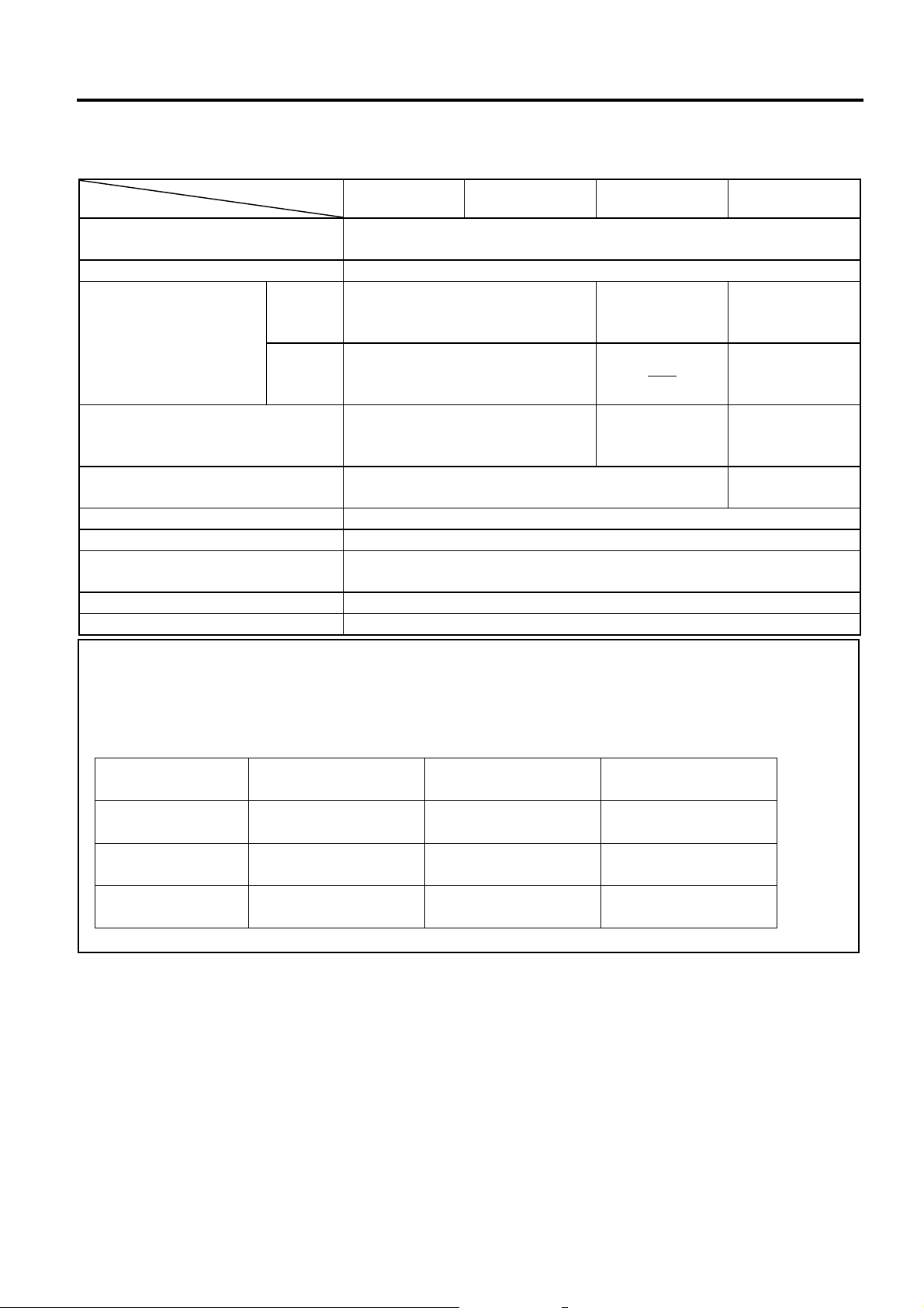
APPENDIX 1 SPECIFICATIONS ENGLISH VERSION EO1-33097
r
r
r
r
r
r
A1.3 Media
A1.3.1 Media Type (Cont.)
Unit: mm (inch)
Item
Media width
(Including backing paper)
Issue mode
Batch mode
Batch mode
-off)
(Tea
Strip mode Cut mode
25.4 to 118.0 (1.00 to 4.65)
Label width 22.4 to 115.0 (0.88 to 4.53)
10 to 999
Label
Media pitch
Tag
(0.39 to 39.3)
See NOTE 3.
10 to 999
(0.39 to 39.3)
See NOTE 3.
8 to 997
Label length
(0.31 to 39.2)
See NOTE 3.
Gap/black mark length 2.0 to 10.0 (0.08 to 0.39)
25.4 to 152.4
(1.0 to 6.0)
See NOTE 3.
-----
23.4 to 150.4
(0.92 to 5.92)
See NOTE 3.
25.4 to 999
(1.0 to 39.3)
See NOTE 3.
25.4 to 999
(1.0 to 39.3)
See NOTE 3.
19.4 to 993
(0.76 to 39.1)
See NOTE 3.
6.0 to 10.0
(0.24 to 0.39)
Black mark width Min. 8.0 (0.31)
Thickness 0.06 to 0.19 (0.0024 to 0.0075)
76.2
3.0)
Ø127 (5.0)
(See NOTE.3)
(See NOTE 2, 3.)
25.4 to 82.2
(1.0 to 3.24)
19.4 to 76.2
(0.76 to 3.0)
76.2
(3.0)
Max. outer roll diameter
Ø203.2 (8.0): When the optional External Media Stand is used.
Roll direction Outside (standard), Inside
Inner core diameter 25.4, 38.1, or 76.2 (1.0, 1.5, or 3.0)
NOTES:
1. To ensure print quality and print head life use only TOSHIBA TEC CORPORATION approved media.
2. When using a media roll of 76.2-mm (3”) inner core diameter, the 3”-Diameter Media Shaft included in the
optional External Media Stand is required.
3. When you use inside wound media, the specifications are restricted as follows:
Unit: mm (inch)
Issue mode
Media pitch
Label length
Inner core diameter
Batch mode /
Batch mode (Tea
10 to 999
(0.39 to 39.3)
8 to 997
(0.31 to 39.2)
(1.5 o
76.2
3.0)
38.1 o
-off)
Strip mode Cut mode
25.4 to 86.2
(1.0 to 3.39)
23.4 to 76.2
(0.92 to 3.0)
38.1 o
(1.5 o
EA1-4
Page 43

APPENDIX 1 SPECIFICATIONS ENGLISH VERSION EO1-33097
A
A1.3.2 Detection Area of the Feed Gap (Transmissive) Sensor
The Transmissive Sensor is fixed and positioned at 6.35 mm right of the centre of the media path.
The Transmissive Sensor detects a gap between labels, as illustrated below.
Sensor position
Min. 2 mm
(Min. 6 mm:
cut mode)
rea to be detected.
Label
Gap
Label
Min. 8 mm
Sensor position
Print side
Media feed direction
6.35mm
A1.3.3 Detection Area of the Black Mark (Reflective) Sensor
The Reflective Sensor is movable within the full range of the media width.
The reflection factor of the Black Mark must be 10% or lower with a waveform length of 950 nm.
The Reflective Sensor should be aligned with the centre of the Black Mark.
Sensor should be positioned at the
centre of the black mark.
Min. 2 mm
Detecting the black marks on the
back.
Min. 8 mm
Media feed direction
Sensor is movable within the full range.
A1.3.4 Effective Print Area
A1.3 Media
The figure below illustrates the relation between the head effective print width and media width.
(for GS Type)
Out of print range
5.0 mm
Print head element
108.0 mm
(Head Effective Print Range)
118.0 mm (Max. media width)
Out of print range
5.0 mm
(for TS Type)
Print head element
Out of print range
6.15 mm
(Head Effective Print Range)
6.15 mm
118.0 mm (Max. media width)
105.7 mm
EA1-5
Out of print range
Page 44

APPENDIX 1 SPECIFICATIONS ENGLISH VERSION EO1-33097
A1.3 Media
The figure below shows the effective print area on the media.
1.5mm from the left edge of media
Start line
1mm
1.5mm from the right edge of media
Guaranteed print area
1mm
Media feed direction
(Backing paper width is not included.)
Media width
NOTES:
1. Be sure not to print on the 1.5-mm wide area from the media edges (shaded area in the above figure).
2. The centre of media should be positioned at the centre of the print head.
3. Print quality is not guaranteed within 3 mm from the print head stop position (including 1-mm slow-up.)
4. Average print (black) rate should be 15% or less. For barcode print area, the print rate should be 30% or less.
5. Line weight should be 3 to 12 dots.
EA1-6
Page 45

APPENDIX 2 INTERFACE ENGLISH VERSION EO1-33097
APPENDIX 2 INTERFACE
APPENDIX 2 INTERFACE
Interface Cables
To prevent radiation and reception of electrical noise, the interface cables must meet the following
requirements:
Fully shielded and fitted with metal or metallized connector housings.
Keep as short as possible.
Should not be bundled tightly with power cords.
Should not be tied to power line conduits.
RS-232C Cable description (only for printers having a serial interface)
The serial data cable used to connect the printer to a host computer should be one of the following two
types (9-pin or 25-pin connector):
Connector to the Host Computer
Function 9 pin 25 pin
RXD 2 3
TXD 3 2
DTR 4 20
GND 5 7
DSR 6 6
RTS 7 4
CTS 8 5
Connector to Printer
Pin No. Function
1 +5V
2 TXD
3 RXD
4 DSR
5 GND
6 RDY
7 N.C.
8 RDY
9 N.C.
NOTE:
Use an RS-232C cable with a connector with inch type securing screws.
EA2-1
Page 46

GLOSSARIES ENGLISH VERSION EO1-33097
GLOSSARIES
Barcode
A code which represents alphanumeric characters
by using a series of black and white stripes in
different widths. Barcodes are used in various
industrial fields: Manufacturing, Hospitals,
Libraries, Retail, Transportation, Warehousing, etc.
Reading barcodes is a fast and accurate means of
capturing data while keyboard entry tends to be
slow and inaccurate.
Batch mode
Issue mode that continuously prints media until the
required number has been printed.
Black mark
A mark printed on the media enabling the printer to
detect the correct start position of the media,
helping to maintain constant print position.
Black mark sensor
A reflective sensor that detects the difference
between a black mark and the print area to find the
print start position.
Cut mode
Printer mode of operation where an (optional)
cutter module is installed to automatically cut
media from the supply roll after they are printed.
The print command can specify to cut every media
or to cut after a set number of media have been
printed.
Direct thermal printing
A printing method using no ribbon, but thermal
media which reacts to heat. The thermal print head
heats the thermal media directly, causing print
image to be printed on the media.
DPI
Dots Per Inch
A unit used to express print density or resolution.
Feed gap sensor
A transmissive sensor that detects the difference
between the gap between labels and the label itself,
to find the print start position of the label.
Font
A complete set of alphanumeric characters in one
style of type. E.g. Helvetica, Courier, Times
GLOSSARIES
Gap
Distance from the bottom of one label to the top of
the next label.
IPS
Inch per second
A unit used to express print speed.
Label
A type of media with adhesive backing supplied on
a backing paper.
Media
Material on which images are printed by the printer.
Label, tag paper, fanfold paper, perforated paper,
etc.
Printer driver
A software program that will convert the
application program’s printing request into the
language that the printer understands.
Print head element
The thermal print head consists of a single line of
tiny resistive elements which when current is
allowed to flow through them it heats up causing a
small dot to be burned onto thermal paper or a
small dot of ink to be transferred from a thermal
ribbon to ordinary paper.
Printing speed
The speed at which printing occurs. This speed is
expressed in units of IPS (inches per second).
Resolution
The degree of detail to which an image can be
duplicated. The minimum unit of divided image is
called a pixel. As the resolution becomes higher,
the number of pixels increases, resulting in a more
detailed image.
Ribbon
An inked film used to transfer an image onto the
media. In the thermal transfer printing, it is heated
by the thermal print head, causing an image to be
transferred onto the media.
Strip mode
One of the printer modes of operation where an
optional Peel-off unit is installed to separate
printed labels from the backing paper one by one.
Page 47

GLOSSARIES ENGLISH VERSION EO1-33097
Supply
Media and ribbon
Tag
A type of media having no adhesive backing but
black marks to indicate the print area. Usually tags
are made of cardboard or other durable material.
Thermal print head
A print head using thermal transfer or thermal
direct printing method.
Thermal transfer printing
A printing method that the thermal print head heats
an ink or resin coating on the ribbon against the
media, causing the ink/resin to transfer onto the
media.
GLOSSARIES
Page 48

© 2015, 2016 TOSHIBA TEC CORPORATIONAll Rights Reserved
1-11-1, Osaki, Shinagawa-ku, Tokyo 141-8562, JAPAN
EO1-33097D
E
R141020P4804-TTEC
Ver04 F 2016-03
 Loading...