

Toshiba B-FV4, B-FV4T-GS, B-FV4T-TS: B-FV4D-GS, B-FV4D-TS, B-FV4D-GH Series Manual
...
TOSHIBA Barcode Printer
B-FV4 SERIES
Printer Manual
Original Jul., 2014
(Revised: Nov., 2016)
Document No. EO18-33030I
This manual includes the contents of the Product Description, and Maintenance Manual.
R140621P0308-TTEC
PRINTED IN JAPAN

Trademarks
• Data MatrixTM is a trademark of International Data Matrix Inc., U.S.
• PDF417TM is a trademark of Symbol Technologies Inc., US.
• QR Code is a trademark of DENSO CORPORATION.
• Maxi Code is a trademark of United Parcel Service of America, Inc., U.S.
• Centronics is a trademark of Centronics Data Computer Corp.
• Windows is a registered trademark of Microsoft Corporation in the United States and/or other
countries.
•
Other company names and product names in this manual are the trademarks of their
respective companies.
Copyright© 2014 - 2016 TOSHIBA TEC CORPORATION All rights reserved
Under the copyright laws, this manual cannot be reproduced in any form without prior
written permission of TOSHIBA TEC CORPORATION.

GENERAL PRECAUTIONS REGARDING THE SERVICE FOR THIS
EQUIPMENT
The installation and service shall be done by a qualified service technician.
1. Installation
- Select a suitable place for installation. Avoid excessive heat, high humidity, dust, vibration and direct
sunlight.
- The equipment shall be installed near the socket outlet and shall be accessible.
- Be sure to fix and plug in the power cable securely after the installation so that no one trips over it.
- When the equipment is used after the option is removed, be sure to install the parts or the covers
which have been taken off so that the inside of the equipment is not exposed.
2. General Precautions at Service
- Be sure to turn the power OFF and unplug the power cable during service.
- Unplug the power cable and clean the area around the prongs of the plug and socket outlet once a
year or more. A fire may occur when dust lies on this area.
- When the parts are disassembled, reassembly is the reverse of disassembly unless otherwise noted
in this manual or other related documents. Be careful not to install small parts such as screws,
washers, pins, E-rings, star washers in the wrong places.
- Basically, the equipment should not be operated with any parts removed or disassembled.
- The PC board must be stored in an anti-electrostatic bag and handled carefully using a wristband
since the ICs on it may be damaged due to static electricity.
Caution:
Before using the wristband, unplug the power cable of the equipment and make sure that
there are no charged objects which are not insulated in the vicinity.
- Be sure not to touch high-temperature sections such as the print head.
- Make sure that the equipment will not operate before touching potentially dangerous places (e.g.
rotating/operating sections such as gears).
- Be careful when removing the covers since there might be the parts with very sharp edges
underneath.
- Use recommended measuring instruments or equivalents.
- Return the equipment to the original state and check the operation when the service is finished.
3. General operations
- Check the procedures and perform them as described in this Manual.
- Avoid exposure to your skin and wear protective gloves as needed.
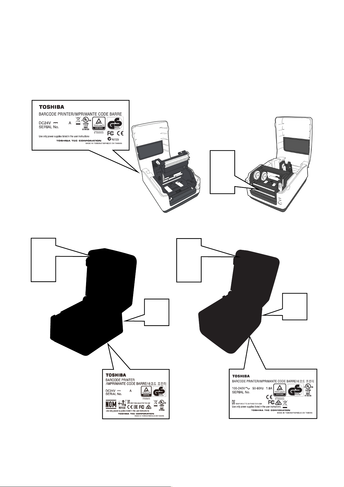
4. Cautionary Labels
- During servicing, be sure to check the rating plate and cautionary labels to see if there is any dirt on
their surface and if they are properly stuck to the equipment.
B-FV4T-GS/TS
B-FV4T-GS12-QM-R
3.75
23xxxxxxx
B-FV4D-GS/TS B-FV4D-GH
B-FV4D-GH14-QM-R
XXXXXXXXX

B-FV4D-GL
5. Disposal of the Equipment, Supplies and Packing Materials
- Regarding the recovery and disposal of the equipment, supplies and packing materials, follow the
relevant local regulations or rules.

ALLGEMEINE SICHERHEITSMASSNAHMEN FÜR DIESES GERÄT
Die Installation und die Wartung sind von einem qualifizierten Service-Techniker durchzuführen.
1. Installation
- Einen geeigneten Standort für die Installation wählen. Standorte mit zuviel Hitze, hoher
Luftfeuchtigkeit, Staub, Vibrieren und direkter Sonneneinstrahlung sind zu vermeiden.
- Das Gerät ist in der Nähe der Steckdose zu installieren; diese muss leicht zu erreichen sein.
- Nach der Installation muss das Netzkabel richtig hineingesteckt und befestigt werden, damit niemand
darüber stolpern kann.
- Falls der Auspackungsstandort und der Installationsstandort des Geräts verschieden sind, die
Bildqualitätsjustierung (automatische Gammajustierung) je nach der Temperatur und
Luftfeuchtigkeit des Installationsstandorts und der Papiersorte, die verwendet wird, durchführen.
2. Allgemeine Sicherheitsmassnahmen in bezug auf die Wartung
- Während der Wartung das Gerät ausschalten und das Netzkabel herausziehen.
- Das Netzkabel herausziehen und den Bereich um die Steckerpole und die Steckdose die Umgebung
in der Nähe von den Steckerzacken und der Steckdose wenigstens einmal im Jahr reinigen. Wenn
Staub sich in dieser Gegend ansammelt, kann dies ein Feuer verursachen.
- Wenn die Teile auseinandergenommen werden, wenn nicht anders in diesem Handbuch usw erklärt,
ist das Zusammenbauen in umgekehrter Reihenfolge durchzuführen. Aufpassen, dass kleine Teile
wie Schrauben, Dichtungsringe, Bolzen, E-Ringe, Stern-Dichtungsringe, Kabelbäume nicht an den
verkehrten Stellen eingebaut werden.
- Grundsätzlich darf das Gerät mit enfernten oder auseinandergenommenen Teilen nicht in Betrieb
genommen werden.
- Das PC-Board muss in einer Anti-elektrostatischen Hülle gelagert werden. Nur Mit einer Manschette
bei Betätigung eines Armbandes anfassen, sonst könnte es sein, dass die integrierten Schaltkreise
durch statische Elektrizität beschädigt werden.
Vorsicht:
Vor Benutzung der Manschette der Betätigung des Armbandes, das Netzkabel des Gerätes
herausziehen und prüfen, dass es in der Nähe keine geladenen Gegenstände, die nicht
isoliert sind, gibt.
- Auf keinen Fall Hochtemperaturbereiche, wie der Druckkopf, berühren.
- Vor dem Berühren potenziell gefährlicher Bereiche (z. B. drehbare oder betriebsrelevante Bereiche,
wie das Getriebe) sicherstellen, dass das Gerät sich nicht bedienen lässt.
- Beim Entfernen von Abdeckungen vorsichtig vorgehen, da sich darunter scharfkantige Komponenten
befinden können.
- Empfohlene oder gleichwertige Messgeräte verwenden.
- Nach Abschluss der Wartungsarbeiten das Gerät in den ursprünglichen Zustand zurück versetzen
und den einwandfreien Betrieb überprüfen.
3. Allgemeine Sicherheïtsmassnahmen
- Die Verfahren sind zu überprüfen und wie im diesem Handbuch beschrieben durchzuführen.
- Um Aussetzung zur Haut zur vermeiden, tragen Sie wenn nötig Schutzhandschuhe.
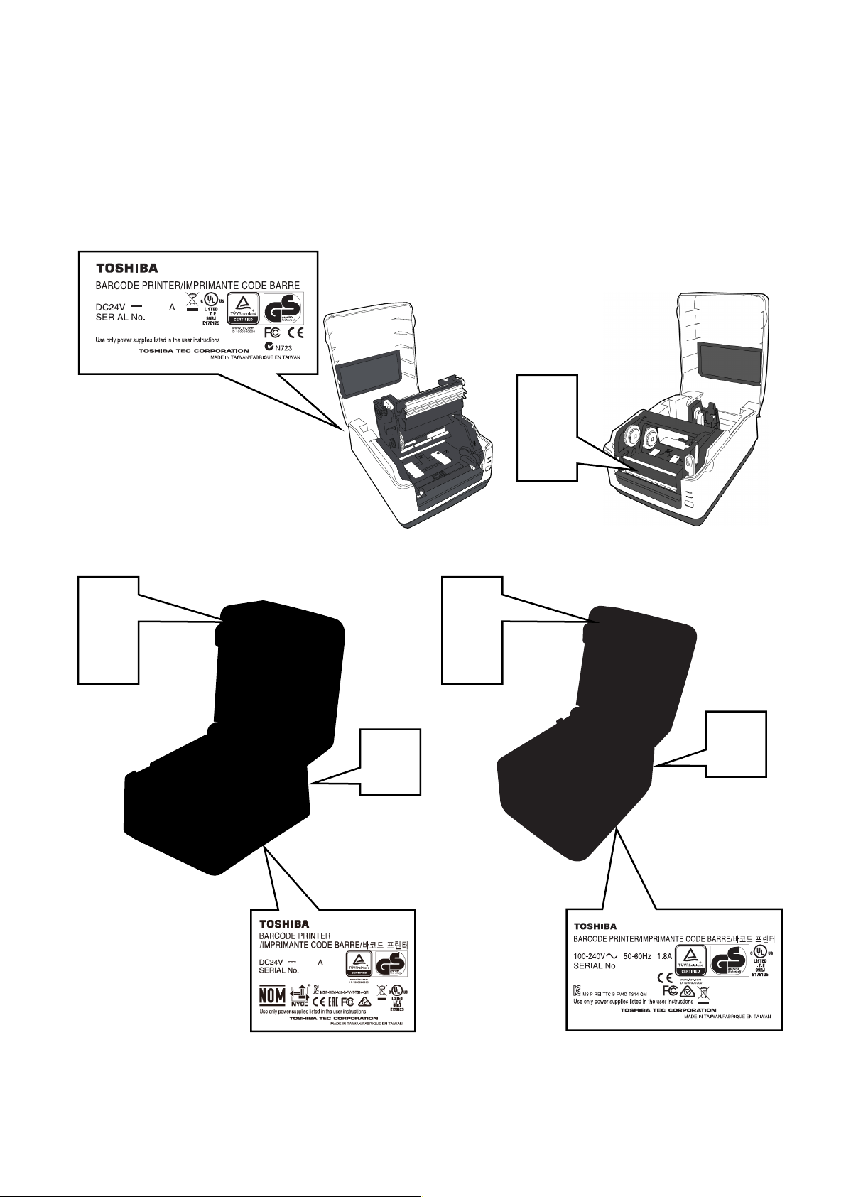
4. Warnetiketten
- Im Rahmen der Wartung unbedingt das Leistungsschild und die Etiketten mit Warnhinweisen
überprüfen, um sicherzustellen, dass sie nicht verschmutzt sind und korrekt am Gerät angebracht
sind.
B-FV4T-GS/TS
B-FV4T-GS12-QM-R
3.75
23xxxxxxx
B-FV4D-GS/TS B-FV4D-GH
B-FV4D-GH14-QM-R
XXXXXXXXX
B-FV4D-GL
5. Entsorgung des Geräts, der Verbrauchs- und Verpackungsmaterialien
- In Bezug auf die Entsorgung und Wiederverwertung des Geräts, der Verbrauchs- und
Verpackungsmaterialien sind die einschlägigen nationalen oder regionalen Vorschriften zu befolgen.

EO18-33030
TABLE OF CONTENTS
Page
1. OUTLINE ------------------------------------------------------------------------------------------------------------- 1- 1
1.1 Features of the B-FV4T series -------------------------------------------------------------------------- 1- 1
1.1.1 Front View ------------------------------------------------------------------------------------------ 1- 1
1.1.2 Rear View ------------------------------------------------------------------------------------------ 1- 3
1.1.3 Interior ----------------------------------------------------------------------------------------------- 1- 5
1.2 Indication of the Model Name --------------------------------------------------------------------------- 1- 8
1.3 Specifications ----------------------------------------------------------------------------------------------- 1- 9
1.3.1 Basic Specifications (for B-FV4T) ------------------------------------------------------------ 1- 9
1.3.2 Basic Specifications (for B-FV4D) ----------------------------------------------------------- 1-11
1.3.3 Basic Specifications (for B-FV4D-GL) ----------------------------------------------------- 1-13
1.3.4 Wireless LAN ------------------------------------------------------------------------------------- 1-15
1.3.5 Bluetooth ------------------------------------------------------------------------------------------- 1-16
1.3.6 Ethernet -------------------------------------------------------------------------------------------- 1-16
1.4 Interface I/O Port ------------------------------------------------------------------------------------------ 1-17
1.4.1 USB ------------------------------------------------------------------------------------------------- 1-17
1.4.2 Ethernet -------------------------------------------------------------------------------------------- 1-17
1.4.3 RS-232C ------------------------------------------------------------------------------------------- 1-18
1.4.4 Centronics ----------------------------------------------------------------------------------------- 1-19
1.5 Key and LED ----------------------------------------------------------------------------------------------- 1-20
1.6 Supply Specifications ------------------------------------------------------------------------------------ 1-21
1.6.1 Media Type ---------------------------------------------------------------------------------------- 1-21
1.6.2 Media Type (B-FV4D-GL) --------------------------------------------------------------------- 1-23
1.6.3 Detection Area of the Feed Gap (Transmissive) Sensor ------------------------------ 1-23
1.6.4 Detection Area of the Black Mark (Reflective) Sensor --------------------------------- 1-24
1.6.5 Effective Print Area ------------------------------------------------------------------------------ 1-24
1.6.6 Ribbon (B-FV4T only) -------------------------------------------------------------------------- 1-25
2. ELECTRONIC SPECIFICATIONS ---------------------------------------------------------------------------- 2- 1
2.1 Main PC Board Diagram --------------------------------------------------------------------------------- 2- 1
2.2 Main PC Board Layout ------------------------------------------------------------------------------------ 2- 3
2.2.1 Type 1 (USB + Ethernet), Type 2 (USB + Ethernet + RS-232C) -------------------- 2- 3
2.2.2 Type 3 (USB + Centronics) ------------------------------------------------------------------- 2- 5
2.3 Main PC Board Connector Pin Assignment --------------------------------------------------------- 2- 6
2.3.1 Pin Assignment for B-FV4T-GS/TS ---------------------------------------------------------- 2- 6
2.3.2 Pin Assignment for B-FV4D-GS/TS --------------------------------------------------------- 2-11
2.3.3 Pin Assignment for B-FV4D-GH ------------------------------------------------------------- 2-15
2.3.4 Pin Assignment for B-FV4D-GL -------------------------------------------------------------- 2-18
2.4 DIP Switch -------------------------------------------------------------------------------------------------- 2-21
3. REPLACING THE IMPORTANT PARTS ------------------------------------------------------------------- 3- 1
3.1 Replacing the Parts for B-FV4T-GS/TS -------------------------------------------------------------- 3- 2
3.1.1 Replacing the Top Cover and the Mid Cover ---------------------------------------------- 3- 2
3.1.2 Replacing the Main PC Board ----------------------------------------------------------------- 3- 5
3.1.3 Replacing the Stepping Motor ----------------------------------------------------------------- 3- 8
3.1.4 Replacing the Feed Gap Sensor / Black Mark Sensor ---------------------------------- 3- 9
3.1.5 Replacing the Ribbon Sensor ---------------------------------------------------------------- 3-12

EO18-33030
3.1.6 Replacing the Platen Roller ------------------------------------------------------------------- 3-13
3.1.7 Replacing the Print Head Assembly -------------------------------------------------------- 3-14
3.2 Replacing the Parts for B-FV4D-GS/TS ------------------------------------------------------------- 3-16
3.2.1 Replacing the Top Cover ---------------------------------------------------------------------- 3-16
3.2.2 Replacing the Platen Roller and the Front Cover --------------------------------------- 3-17
3.2.3 Replacing the Bottom Cover and the Main PC Board ---------------------------------- 3-18
3.2.4 Replacing the Mid Cover ---------------------------------------------------------------------- 3-19
3.2.5 Replacing the Stepping Motor ---------------------------------------------------------------- 3-20
3.2.6 Replacing the Media Sensor [Feed Gap Senor (Lower) / Black Mark Sensor] -- 3-21
3.2.7 Replacing the Feed Gap Sensor (Upper) ------------------------------------------------- 3-22
3.2.8 Replacing the Micro Switch ------------------------------------------------------------------- 3-24
3.2.9 Replacing the Print Head Assembly -------------------------------------------------------- 3-25
3.2.10 Replacing the Media Holder ------------------------------------------------------------------ 3-26
3.3 Replacing the Parts for B-FV4D-GH/GL ------------------------------------------------------------- 3-28
3.3.1 Replacing the Top Cover ---------------------------------------------------------------------- 3-28
3.3.2 Replacing the Platen Roller ------------------------------------------------------------------- 3-29
3.3.3 Replacing the Power Adapter Cover and the Power Adapter ------------------------ 3-30
3.3.4 Replacing the Bottom Cover and the Main PC Board ---------------------------------- 3-32
3.3.5 Replacing the Mid Cover ---------------------------------------------------------------------- 3-34
3.3.6 Replacing the Stepping Motor ---------------------------------------------------------------- 3-35
3.3.7 Replacing the Feed Gap Sensor (Lower) [Media Sensor] ---------------------------- 3-36
3.3.8 Replacing the Feed Gap Sensor (Upper) [Media Sensor] ---------------------------- 3-37
3.3.9 Replacing the Micro Switch ------------------------------------------------------------------- 3-39
3.3.10 Replacing the Print Head Assembly -------------------------------------------------------- 3-40
3.3.11 Replacing the Media Holder Lever ---------------------------------------------------------- 3-41
3.3.12 Replacing the Peel-off unit and the Peel-off sensor (B-FV4D-GH only) ----------- 3-42
3.3.13 Replacing the Cutter Unit (B-FV4D-GL only) --------------------------------------------- 3-44
4. TROUBLESHOOTING ------------------------------------------------------------------------------------------- 4- 1
4.1 LED Status --------------------------------------------------------------------------------------------------- 4- 1
4.2 Print Quality -------------------------------------------------------------------------------------------------- 4- 2
5. MAINTENANCE ---------------------------------------------------------------------------------------------------- 5- 1
5.1 Cleaning of the Printer ------------------------------------------------------------------------------------ 5- 1
5.2 Cleaning of the Optional Cutter Module -------------------------------------------------------------- 5- 2
5.3 Cleaning of the Cutter Module (B-FV4D-GL Series) ---------------------------------------------- 5- 6
6. SYSTEM MODE ---------------------------------------------------------------------------------------------------- 6- 1
6.1 Feed Gap Sensor / Black Mark Sensor Adjustments --------------------------------------------- 6- 2
6.2 Parameter Clear -------------------------------------------------------------------------------------------- 6- 3
6.3 TPCL Auto Call Cancellation ---------------------------------------------------------------------------- 6- 5
6.4 BASIC Interpreter Disable ------------------------------------------------------------------------------- 6- 5
6.5 Self-Test Printing / Dump Mode ------------------------------------------------------------------------ 6- 6
6.5.1 Self-Test -------------------------------------------------------------------------------------------- 6- 6
6.5.2 Dump Mode --------------------------------------------------------------------------------------- 6-21
7. B-FV SETTING TOOL -------------------------------------------------------------------------------------------- 7- 1
7.1 Installing B-FV Setting Tool (V1.0.21) ---------------------------------------------------------------- 7- 1
7.2 Working with B-FV Setting Tool (V1.0.21) ----------------------------------------------------------- 7- 4
7.2.1 Menu bar -------------------------------------------------------------------------------------------- 7- 4
7.2.2 Toolbar ---------------------------------------------------------------------------------------------- 7- 6
7.2.3 Navigation Pane --------------------------------------------------------------------------------- 7-10
7.3 Installing B-FV Setting Tool (V1.0.27) --------------------------------------------------------------- 7-35

EO18-33030
7.4 Working with B-FV Setting Tool (V1.0.27) ---------------------------------------------------------- 7-38
7.4.1 Menu bar ------------------------------------------------------------------------------------------- 7-38
7.4.2 Toolbar --------------------------------------------------------------------------------------------- 7-40
7.4.3 Navigation Pane --------------------------------------------------------------------------------- 7-44
7.5 Installing B-FV Setting Tool (V1.0.34) --------------------------------------------------------------- 7-80
7.6 Working with B-FV Setting Tool (V1.0.34) ---------------------------------------------------------- 7-83
7.6.1 Menu bar ------------------------------------------------------------------------------------------- 7-83
7.6.2 Toolbar --------------------------------------------------------------------------------------------- 7-85
7.6.3 Navigation Pane --------------------------------------------------------------------------------- 7-89
8. UPDATING FIRMWARE ----------------------------------------------------------------------------------------- 8- 1
8.1 Updating Firmware in B-FV Setting Tool (V1.0.27 or earlier) ----------------------------------- 8- 1
8.1.1 Updating via USB or COM Port --------------------------------------------------------------- 8- 1
8.1.2 Updating via LAN or Multi-LAN Port --------------------------------------------------------- 8- 6
8.2 Updating Firmware via USB Host (V1.0.27 or earlier) ------------------------------------------- 8-11
8.3 Updating Firmware in Atmel Mode -------------------------------------------------------------------- 8-12
8.4 Updating Firmware in B-FV Setting Tool (V1.0.34 or later)------------------------------------- 8-16
8.4.1 Updating via USB or COM Port -------------------------------------------------------------- 8-16
8.4.2 Updating via LAN or Multi-LAN Port -------------------------------------------------------- 8-22
8.5 Updating Firmware via USB Host (V1.0.34 or later) ---------------------------------------------- 8-28
9. NETWORK ---------------------------------------------------------------------------------------------------------- 9- 1
9.1 Network Architecture -------------------------------------------------------------------------------------- 9- 1
9.2 SNMP Trap -------------------------------------------------------------------------------------------------- 9- 3
9.3 MIB List ------------------------------------------------------------------------------------------------------- 9- 4
9.4 Ethernet Status Indicators ------------------------------------------------------------------------------- 9- 4
APPENDIX --------------------------------------------------------------------------------------------------------------- A- 1
Establishing a Bluetooth connection with B-FV4D and B-FV4T --------------------------------------- A- 1

EO18-33030
CAUTION!
1. This manual may not be copied in whole or in part without prior written permission of TOSHIBA TEC.
2. The contents of this manual may be changed without notification.
Copyright© 2014 - 2016 TOSHIBA TEC CORPORATION All rights reserved
1-11-1, Osaki, Shinagawa-ku, Tokyo 141-8562, JAPAN

1. OUTLINE EO18-33030
t
1.1 Feature of the B-FV4 series
1. OUTLINE
1.1 Feature of the B-FV4 series
1.1.1 Front View
B-FV4T-GS/TS
Media Outle
B-FV4D-GS/TS
Media Outlet
LED 2
LED 1
Media View Window
LED 2
LED 1
FEED Button
Media View Window
FEED Button
1-1

1. OUTLINE EO18-33030
1.1 Feature of the B-FV4 series
B-FV4D-GH
LED 2
Media View Window
LED 1
FEED Button
Media Outlet
B-FV4D-GL
LED 2
LED 1
Media View Window
Media Outlet
FEED Button
1-2
1. OUTLINE EO18-33030
1.1 Feature of the B-FV4 series
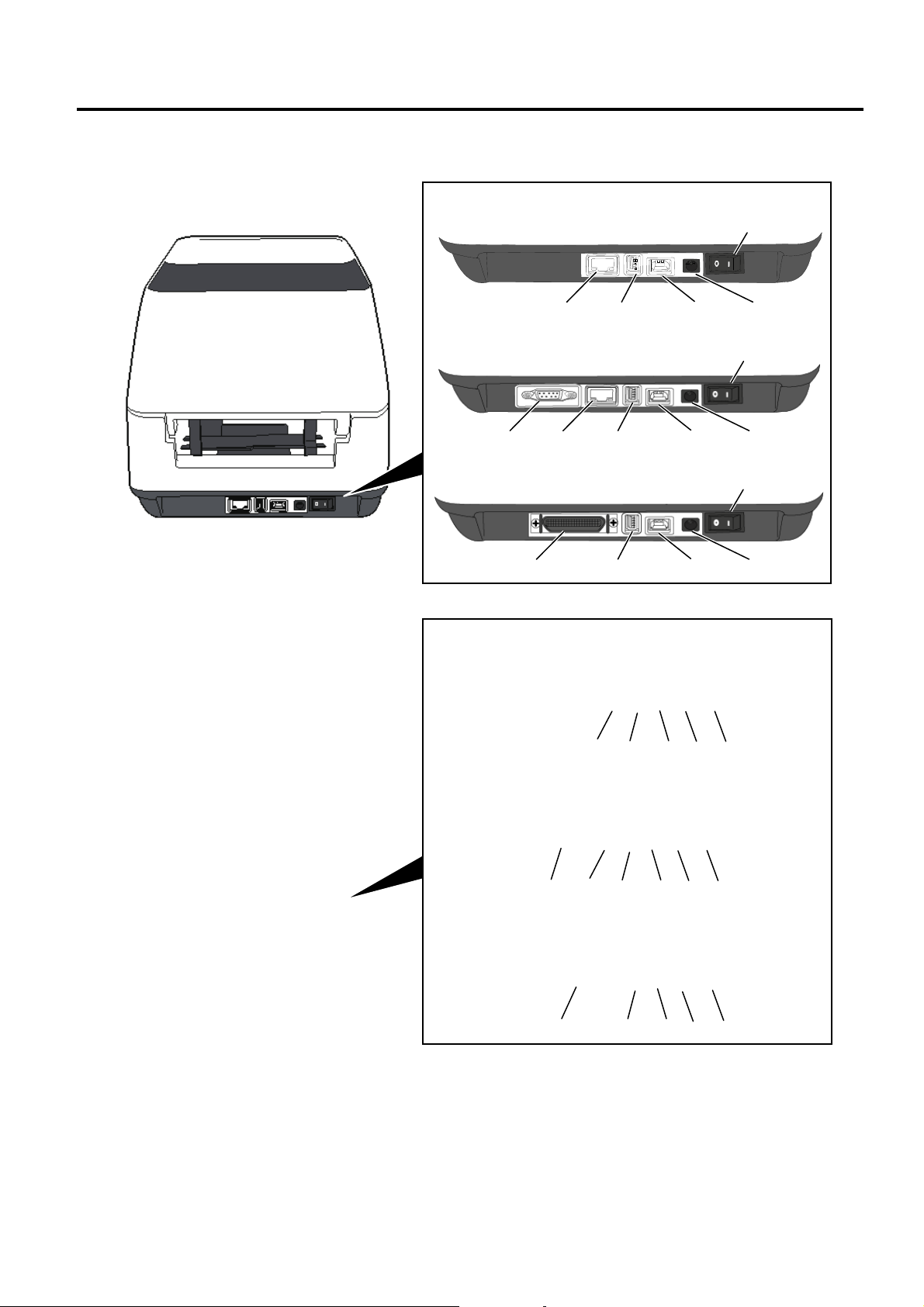
1.1.2 Rear View
B-FV4T-GS/TS
B-FV4D-GS/TS
Printer having the USB and Ethernet Interfaces
Printer having the Serial Interface (RS-232C)
Printer having the Parallel Interface (Centronics)
Printer having the USB and Ethernet Interfaces
Printer having the Serial Interface (RS-232C)
Printer having the Parallel Interface (Centronics)
Power Switch
Power Jack
USB Interface for connecting to a host computer
USB Host Interface for connecting a USB memory device.
Ethernet Interface
Serial Interface (RS-232C)*
* Some models have no serial interface (RS-232C).
Parallel Interface (Centronics)
1-3
1. OUTLINE EO18-33030
1.1 Feature of the B-FV4 series
B-FV4D-GH / B-FV4D-GL
Printer having the USB, Ethernet and Serial Interfaces
Power Switch
Power Jack
Remark:
Make sure that the Power Jack is connected to the printer as shown above.
USB Interface for connecting a host computer
USB Interface for connecting a USB memory
Ethernet Interface
Serial Interface (RS-232C)
AC Power Inlet
1-4
1. OUTLINE EO18-33030
1.1 Feature of the B-FV4 series
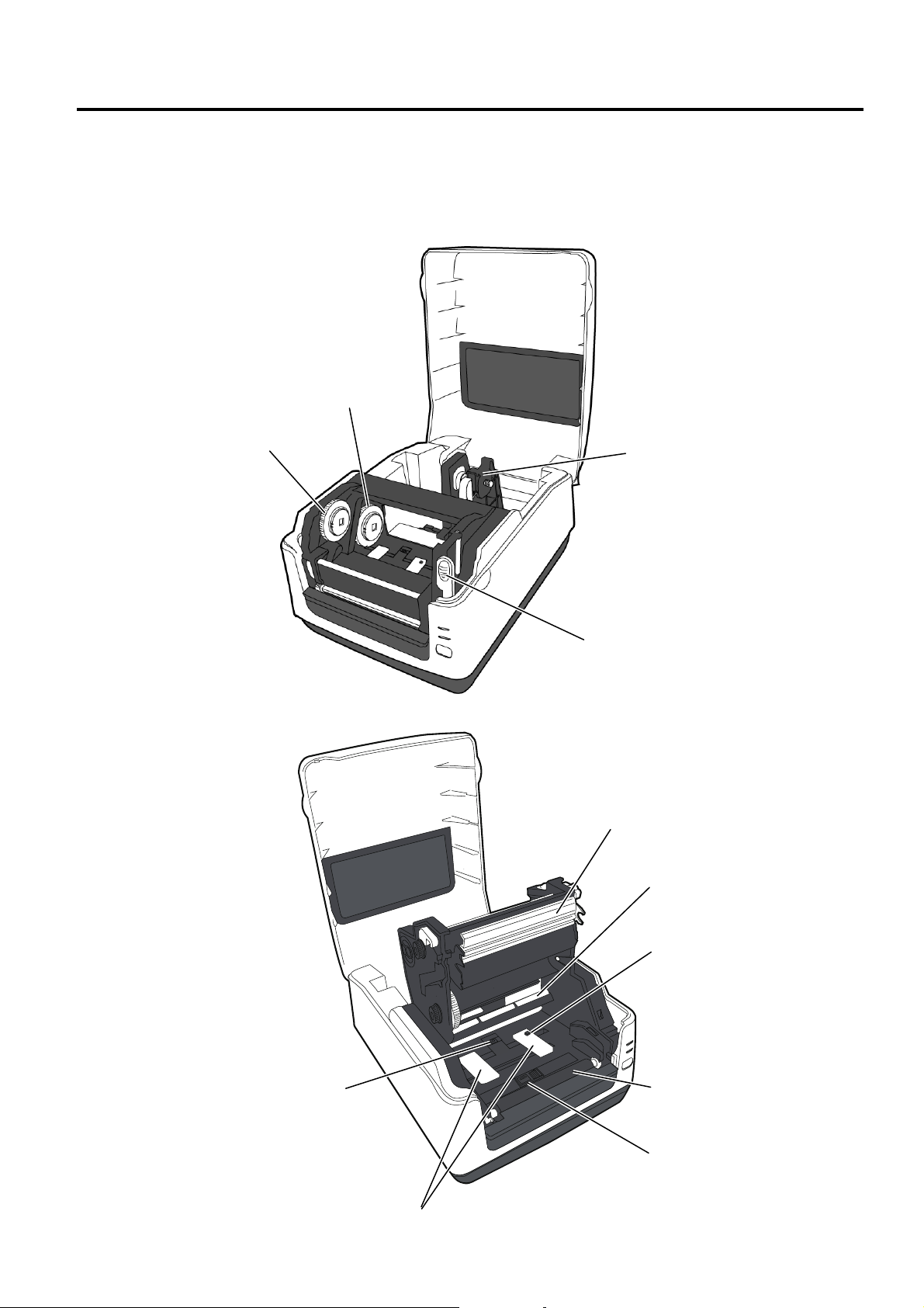
1.1.3 Interior
B-FV4T -GS/TS
View 1
Take-Up Gear
View 2
Feed Gap Sensor
Supply Gear
Media Roll Holders
Print Head Release Latch
Print Head
Media Guide Roller
Lock Button
Platen Roller
Black Mark Sensor
Media Guides
1-5

1. OUTLINE EO18-33030
1.1 Feature of the B-FV4 series
B-FV4D-GS/TS
Print Head
Feed Gap Sensor
Core Holders
Media Roll Holders
Thumbscrew
Holder Lock Lever
Media Guides
Black Mark Sensor
Platen Roller
B-FV4D-GH
Print Head
Media Roll Holder Lever
Media Roll Holders
Media Sensor
Lock Release Portions
Media Guide
Platen Roller
Peel-off Unit
Thumbscrew
Peel-off Sensor
Media Guide
1-6

1. OUTLINE EO18-33030
1.1 Feature of the B-FV4 series
B-FV4D-GL
Print Head
Media Roll Holder Lever
Lock Release Portions
Transmissive Senso r
Cutter Sensor
Cutter Tray
Media Roll Holders
Cutter Unit
1-7

1. OUTLINE EO18-33030
1.2 Indication of the Model Name
1.2 Indication of the Model Name
B - F V 4 T - G S 1 2 - QM - Cxx - R
RoHS Compliance
R : RoHS compliant model
Custom code
(blank) : Standard model
Cxx : Custom model
(x : 0 to 9, A to Z or blank)
Destination country/region code
QM : Standard for World Wide (Except China)
CN : China
QP : Europe
QQ : North America
Interface
0 : USB + RS-232C
2 : USB + Ethernet (Standard type for Worldwide)
4 : USB + Ethernet + RS-232C
6 : USB + Centronics
H/W version
1 : Version 1
2 : Version 2
Printing style
S : Standard
H : Peel-off
C : Cutter
L : Cutter for label without liner
Print resolution
G : 8 dots/mm (203 dpi)
T : 11.8 dots/mm (300 dpi)
Print method
D : Direct thermal
T : Thermal transfer & Direct thermal
Print width
4 : 4inch
1-8
1. OUTLINE EO18-33030
1.3 Specifications
1.3 Specifications
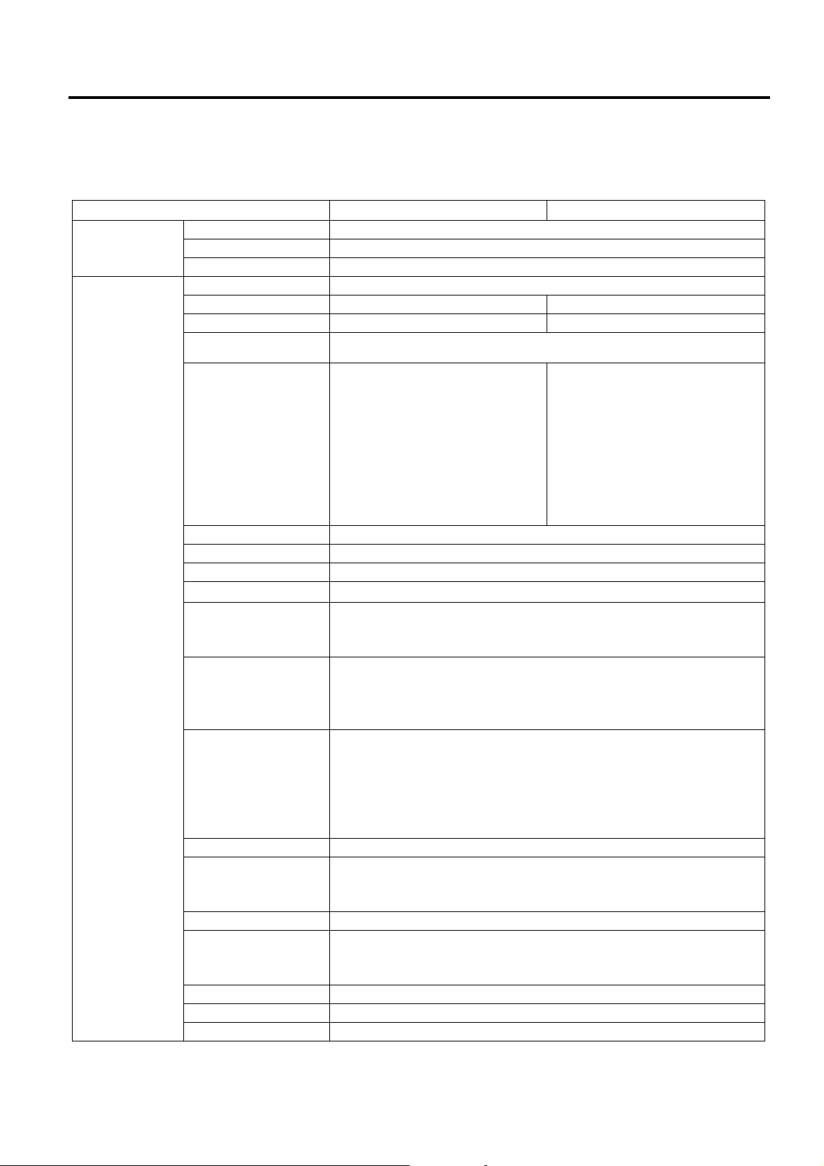
1.3.1 Basic Specifications (for B-FV4T)
Model B-FV4T-GS Series B-FV4T-TS Series
General
Characteristics
Printer
characteristics
Construction Double walled casing & Clam shell design
Maintenance No tool required to repair thermal head and platen
Paper holder No roll spindle & No paper holder spring
Print method Direct thermal & thermal transfer
Resolution 203 dpi (8 dots/mm) 300 dpi (11.8 dots/mm)
Print width Max. 108 mm (4.25”) Max. 105.7 mm (4.16”)
Print length Max. 999 mm (39”)
Batch/Cut mode:
50.8 mm/sec. (2”/sec.),
76.2 mm/sec. (3”/sec.),
101.6 mm/sec. (4”/sec.),
Print Speed
RAM 32 MB SDRAM
Flash ROM 16 MB
User area 3 MB
Optional memory Max. 16 GB USB
Media sensors
I/F (User installable)
Barcode Linear
Printer Language TPCL (Refer to External Equipment I/F manual)
2D Barcode Data Matrix, PDF417,
Composite symbol GS1-128 Composite (CC-A/CC-B/CC-C)
Fonts Times Roman (6 size s), Helvetica (6 sizes), Presentation (1 size),
LED Two LEDs w/ 3 colors (w/ silk screen print of “STATUS”, “1”, and “2”)
Key Feed key (w/ silk screen print of “FEED”)
Switch Power S/W
127 mm/sec. (5”/sec.),
152.4 mm/sec. (6”/sec.)
Strip mode:
50.8 mm/sec. (2”/sec.),
76.2 mm/sec. (3”/sec.)
Feed gap sensor (Transmissive)
Black mark sensor (Reflective)
Ribbon sensor (Reflective encoder sensor)
Serial interface RS-232C
Parallel interface (Centronics)
USB 2.0 full Speed
Ethernet interface (10/100 Base)
UPC-A, UPC-E, EAN8/13,
UPC-A add on 2&5, UPC-E add on 2&5,
EAN-8/13 add on 2&5,
CODE39, CODE93, CODE128, GSI-128(UCC/EAN128),
NW7, MSI, Industrial 2 of 5, ITF, POSTNET, RM4SCC, KIX-Code,
USPS Intelligent mail barcode, GS1 DataBar
QR Code, Maxi Code,
Micro PDF417
Letter Gothic (1 size), Courier (2 sizes), Prestige Elite (2 sizes),
OCR-A (1 type), OCR-B (1 type), Simplified Chinese (1 size)
Batch/Cut mode:
50.8 mm/sec. (2”/sec.),
76.2 mm/sec. (3”/sec.),
101.6 mm/sec. (4”/sec.)
Strip mode:
50.8 mm/sec. (2”/sec.),
76.2 mm/sec. (3”/sec.)
1-9
1. OUTLINE EO18-33030
Model B-FV4T-GS Series B-FV4T-TS Series
Operating
characteristics
Physical
characteristics
Related products Options Full cutter module (B-FV204T-F-QM-R)
Operating temperature
Storage temperature -20C to 60C (-4F to 140F)
Operating humidity 25 to 85 % (Non-condensing R.H) (*1)
Storage humidity 10 to 90 % (Non-condensing R.H)
Electrical
Agency approvals FCC Class A
Environmental
complaint
Width 220.6 mm (8.7”)
Height 182.0 mm (7.2”)
Depth 278.5 mm (11.0”)
Weight 2.4Kg (5.29 lb) (Excluding media and ribbon)
Accessories CD-ROM (1 copy)
5C to 40C (41F to 104F) (*1)
AC Adapter
100 to 240 VAC ± 10%, 47 to 63 Hz
Power consumption (100 to 120 V)
During standby: 0.07 A, 3.4 W maximum
During a print job: 0.90 A, 49.0 W maximum
Power consumption (200 to 240 V)
During standby: 0.05 A, 3.5 W maximum
During a print job: 0.47 A, 48.1 W maximum
Inrush Current
115 to 230 VAC: 90 A
C-Tick
CE
TUV-GS
UL, cUL
RoHS
WEEE
Partial cutter module (B-FV204T-P-QM -R)
Peel-off module (B-FV904T-H-QM-R)
External media stand (B-FV904-PH-QM-R)
Bluetooth interface (B-FV704T-BLTH-QM-R)
TPH kit (B-FV704-TPH2-QM-R) TPH kit (B-FV704-TPH3-QM-R)
Power Adapt er (1 pc.)
Quick Installation Manual (1 copy)
Safety Precautions (1 copy)
USB cable (1pc.)
1-inch Ribbon S pindle (2 pcs.)
0.5-inch Ribbon S pindle (2 pcs.)
Paper Support Roller for Outside-wound Media (1 pc.)
1.3 Specifications
NOTES:
*1 Since the adhesive strength of labels becomes higher in hot and humid conditions, the possibility of
label jam increases.
1-10
1. OUTLINE EO18-33030
1.3 Specifications
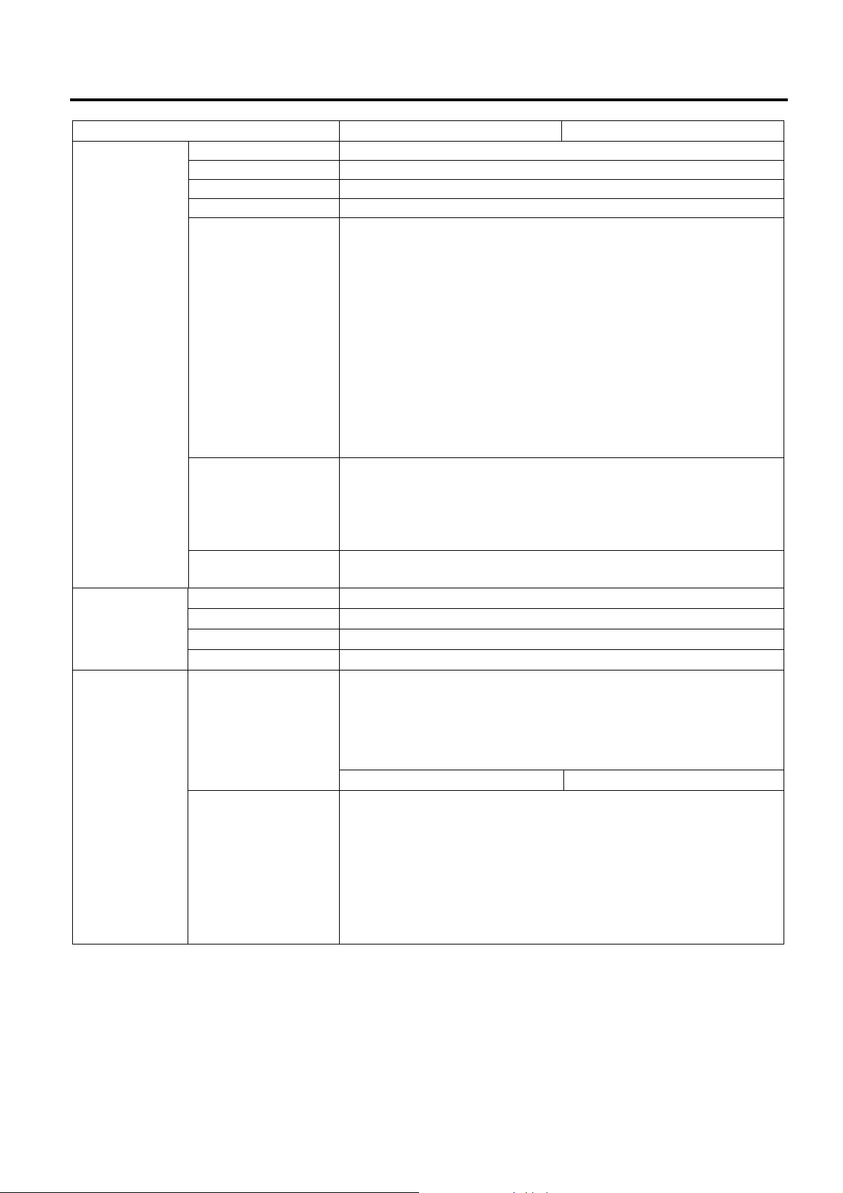
1.3.2 Basic Specifications (for B-FV4D)
Model B-FV4D-GS Series B-FV4D-TS Series B-FV4D-GH Series
General
Characteristics
Printer
characteristics
Construction Double walled casing & Clam shell design
Maintenance No tool required to repair thermal head and platen
Paper holder No roll spindle & No p aper holder spring
Print method Direct thermal
Resolution 203 dpi (8 dots/mm) 300 dpi (11.8 dot s/mm) 203 dpi (8 dots/mm)
Print width Max. 108 mm (4.25”) Max. 105.7 mm (4.16”) Max. 99.0 mm (3.89”)
Print length Max. 999 mm (39”)
Batch/Cut mode:
50.8 mm/sec. (2”/sec.),
76.2 mm/sec. (3”/sec.),
101.6 mm/sec.
(4”/sec.),
Print Speed
RAM 32 MB SDRAM
Flash ROM 16 MB
User area 3 MB
Optional
memory
Media sensors
I/F (User
installable)
Barcode Linear
Printer
Language
2D Barcode Data Matrix, PDF417,
Composite
symbol
Fonts Times Roman (6 sizes), Helvetica (6 sizes), Presentat ion (1 size),
LED Two LEDs w/ 3 colors (w/ silk screen print of “STATUS”, “1”, and “2”)
Key Feed key (w/ silk screen print of “FEED”)
Switch Power S/W
127 mm/sec. (5”/sec.),
152.4 mm/sec.
(6”/sec.)
Strip mode:
50.8 mm/sec. (2”/sec.),
76.2 mm/sec. (3”/sec.)
Max. 16 GB USB
Feed gap sensor (Transmissive)
Black mark sensor (Reflective)
Serial interface RS-232C
Parallel interface (Centronics)
USB 2.0 full Speed
Ethernet interface (10/100 Base)
UPC-A, UPC-E, EAN8/13,
UPC-A add on 2&5, UPC-E add on 2&5,
EAN-8/13 add on 2&5,
CODE39, CODE93, CODE128, GSI-128(UCC/EAN128),
NW7, MSI, Industrial 2 of 5, ITF, POSTNET, RM4SCC, KIX-Code,
USPS Intelligent mail barcode, GS1 DataBar
TPCL (Refer to External Equipment I/F manual)
QR Code, Maxi Code,
Micro PDF417
GS1-128 Composite (CC-A/CC-B/CC-C)
Letter Gothic (1 size), Courier (2 sizes), Prestige Elite (2 sizes),
OCR-A (1 type), OCR-B (1 type), Simplified Chinese (1 size)
Batch/Cut mode:
50.8 mm/sec. (2”/sec.),
76.2 mm/sec. (3”/sec.),
101.6 mm/sec. (4”/sec.)
Strip mode:
50.8 mm/sec. (2”/sec.),
76.2 mm/sec. (3”/sec.)
Batch mode:
50.8 mm/sec. (2”/sec.),
76.2 mm/sec. (3”/sec.),
101.6 mm/sec.
(4”/sec.),
127 mm/sec. (5”/sec.),
152.4 mm/sec.
(6”/sec.)
Strip mode:
50.8 mm/sec. (2”/sec.),
76.2 mm/sec. (3”/sec.)
Feed gap sensor
(Transmissive)
Serial interface RS-232C
USB 2.0 full Speed
Ethernet interface (10/100
Base)
1-11
1. OUTLINE EO18-33030
1.3 Specifications
Model B-FV4D-GS Series B-FV4D-TS Series B-FV4D-GH Series
Operating
characteristics
Physical
characteristics
Related
products
Operating temperature 5C to 40C (41F to 104F) (*1)
Storage temperature -20C to 60C (-4F to 140F)
Operating humidity 25 to 85 % (Non-condensing R.H) (*1)
Storage humidity 10 to 90 % (Non-condensing R.H)
AC Adapter
B-FV4D- GS/TS Series
100 to 240 VAC ± 10%, 47 to 63 Hz
B-FV4D-GH Series
100 to 240 VAC ± 10%, 50 to 60 Hz
Power consumption (100 to 120 V)
Electrical
Agency approvals FCC Class A, C-Tick, CE, TUV-GS, UL, cUL
Environmental
complaint
Width 183.8 mm (7.2”) 183.8 mm (7.2”)
Height 166.9 mm (6.5”) 198.7 mm (7.8”)
Depth 226.2 mm (8.9”) 244.5 mm (9.6”)
Weight 1.76Kg (3.8 lb) (Excluding media)
Options
Accessories
During standby: 0.12 A, 3.7 W maximum
During a print job: 1.0 A, 60 W maximum
Power consumption (200 to 240 V)
During standby: 0.07 A, 3.8 W maximum
During a print job: 0.6 A, 59 W maximum
Inrush Current
100 VAC: 40 A, 240 VAC: 80 A At cold start, maximum load
RoHS,
WEEE
2.2Kg (4.9 lb)
(Excluding media)
Full cutter module (B-FV204D-F-QM-R)
Partial cutter module (B-FV204D-P-QM-R)
Peel-off module (B-FV904D-H-QM-R)
External media stand (B-FV904-PH-QM-R)
Bluetooth interface (B-FV704D-BLTH-QM-R)
CD-ROM (1 copy)
Power Adapt er (1 pc.)
Quick Installation Manual (1 copy)
Safety Precautions (1 copy)
USB cable (1pc.)
CD-ROM (1 copy)
Quick Installation
Manual (1 copy)
Safety Precautions
(1 copy)
USB cable (1pc.)
N/A
NOTES:
*1 Since the adhesive strength of labels becomes higher in hot and humid conditions, the possibility of
label jam increases.
1-12

1. OUTLINE EO18-33030
1.3 Specifications
1.3.3 Basic Specifications (for B-FV4D-GL)
Model B-FV4D-GL Series
General
Characteristics
Printer
characteristics
Construction Double walled casing & Clam shell design
Maintenance No tool required to repair thermal head and platen
Paper holder No roll spindle & No p aper holder spring
Print method Direct thermal
Resolution 203 dpi (8 dots/mm)
Print width Max. 99.0 mm (3.89”)
Print length Max. 152.4 mm (6.0”)
Cut mode:
50.8 mm/sec. (2”/sec.),
Print Speed
RAM 32 MB SDRAM
Flash ROM 16 MB
User area 3 MB
Optional
memory
Media sensor Paper End Sensor (Transmissive)
I/F (User
installable)
Barcode Linear
Printer
Language
2D Barcode Data Matrix, PDF417,
Composite
symbol
Fonts Times Roman (6 sizes), Helvetica (6 sizes), Presentat ion (1 size),
LED Two LEDs w/ 3 colors (w/ silk screen print of “STATUS”, “1”, and “2”)
Key Feed key (w/ silk screen print of “FEED”)
Switch Power S/W
76.2 mm/sec. (3”/sec.),
101.6 mm/sec. (4”/sec.),
127 mm/sec. (5”/sec.),
152.4 mm/sec. (6”/sec.)
Max. 16 GB USB
Serial interface RS-232C
USB 2.0 full Speed
Ethernet interface (10/100 Base)
UPC-A, UPC-E, EAN8/13,
UPC-A add on 2&5, UPC-E add on 2&5,
EAN-8/13 add on 2&5,
CODE39, CODE93, CODE128, GSI-128(UCC/EAN128),
NW7, MSI, Industrial 2 of 5, ITF, POSTNET, RM4SCC, KIX-Code,
USPS Intelligent mail barcode, GS1 DataBar
TPCL (Refer to External Equipment I/F manual)
QR Code, Maxi Code,
Micro PDF417
GS1-128 Composite (CC-A/CC-B/CC-C)
Letter Gothic (1 size), Courier (2 sizes), Prestige Elite (2 sizes),
OCR-A (1 type), OCR-B (1 type), Simplified Chinese (1 size)
1-13

1. OUTLINE EO18-33030
Operating
characteristics
Physical
characteristics
Related
products
Model B-FV4D-GL Series
Operating temperature 5C to 35C (41F to 95F) (*1)
Storage temperature -20C to 60C (-4F to 140F)
Operating humidity 30 to 75 % (Non-condensing R.H) (*1)
Storage humidity 10 to 90 % (Non-condensing R.H)
AC Adapter
100 to 240 VAC ± 10%, 50 to 60 Hz
Power consumption (100 to 120 V)
During standby: 0.12 A, 3.7 W maximum
During a print job: 1.0 A, 60 W maximum
Electrical
Agency approvals RCM, CE, TUV-GS
Environmental
complaint
Width 184.0 mm (7.2”)
Height 198.8 mm (7.8”)
Depth 271.2 mm (10.7”)
Weight 2.8Kg (6.2 lb) (Excluding media)
Options
Accessories
Power consumption (200 to 240 V)
During standby: 0.07 A, 3.8 W maximum
During a print job: 0.6 A, 59 W maximum
Inrush Current
100 VAC: 40 A, 240 VAC: 80 A At cold start, maximum load
RoHS,
WEEE
N/A
CD-ROM (1 copy)
Quick Installation Manual (1 copy)
Safety Precautions (1 copy)
USB Cable (1pc.)
Scraper (1 pc.)
Cleaner Pen (1 pc.)
Cutter Tray (1 pc.)
1.3 Specifications
NOTES:
*1 Since the adhesive strength of labels becomes higher in hot and humid conditions, the possibility of
label jam increases.
1-14
1. OUTLINE EO18-33030
1.3 Specifications
1.3.4 Wireless LAN
Properties Wireless LAN I/F
Hardware
Software Connection mode Infrastructure, Adhoc
Protocol IEEE 802.11 b/g
Enabled Device B-FV4 Series
Operating Temperature +5°C ~ +40°C
Destination USA Europe
Frequency
(Center Channel)
Channel 1 ~ 11 ch 1 ~ 13 ch
Spacing 5 MHz
Transmission Speed/
Modulation
Antenna External antenna
Aerial power 802.11b 10 dBm Max
2412 ~ 2462 MHz 2412 ~ 2472 MHz
IEEE
802.11b
IEEE
802.11g
IEEE
802.11n
802.11g 10 dBm Max
802.11n N/A
Transmission
Method
Channel
Data Transmission
Speed/Modulation
Transmission
Method
Channel Depending on the
Data Transmission
Speed/Modulation
Transmission
Method
Channel
Data Transmission
Speed/Modulation
Conforming to IEEE 802.11b
DSSS method
Depending on the
country/region
11/5.5 Mbps: CCK
2 Mbps: DQPSK
1 Mbps: DBPSK
Conforming to IEEE 802.11g
OFDM method
DSSS method
country/region
54/48 Mbps: 64 QAM
36/24 Mbps: 16 QAM
18/12 Mbps: QPSK
9/6 Mbps: BPSK
N/A
N/A
N/A
Default IP Address 192.168.xxx.yyy Set the printer ID for xxx.yyy.
Default Subnet Mask
Default ESSID
Security
Protocol
Wireless LAN Parameter
Setting and Status
Monitor
Cryptography
Authorization
255.255.0.0
TOSHIBATEC
IEEE 802.11i
WEP 128 bit, TKIP (WPA), AES (WPA2)
Open Key (for WEP), PSK
TCP/IP, Socket, DHCP
Parameter Setting: Command (PC Setting Tool)
1-15
1. OUTLINE EO18-33030
1.3 Specifications
1.3.5 Bluetooth
Properties Bluetooth I/F
Standard Bluetooth 2.1 + EDR or later
Enable Device B-FV4 Series
Operating Temperature 41°F (5°C) ~ 104°F (40°C)
Storage Temperature -4°F (-20°C) ~ 140°F (60°C)
Operating Humidity 25 ~ 85 % Non-condensing R.H
Storage Humidity 10 ~ 90 % Non-condensing R.H
Connection Form Only one-to-one connection is supported.
Support Profile Serial Port Profile (SPP)
PIN code is supported.
Class of Radio Transmission CLASS 2
Transmission Method Bi-direction al (Half-duplex)
Flow Control Credit based flow control
Operating Mode Slave Mode
Transmission Distance 3 m (360 degrees)
SR Mode in Page/Inquiry Scanning R1 Scan Interval 1.28 sec.
Scan Window 22.5 msec.
RF Frequency Range 2402 ~ 2480 MHz
Nominal Output Power +4 dBm (2.51 mW) MAX
1.3.6 Ethernet
Properties Description
Port RJ-45
Speed 10Base-T/100Base-T (Auto Detecting)
Protocol ARP, IP, ICMP, UDP, TCP, HTTP, DHCP, Socket, LPR,
IPv4, SNMPv2
Mode TCP Server/Client, UDP Client
T echnology HP Auto-MDIX, Auto-Negotiation
1-16
1. OUTLINE EO18-33030
1.4 Interface I/O Port
1.4 Interface I/O Port
This section provides information about IO port specifications for your printer.
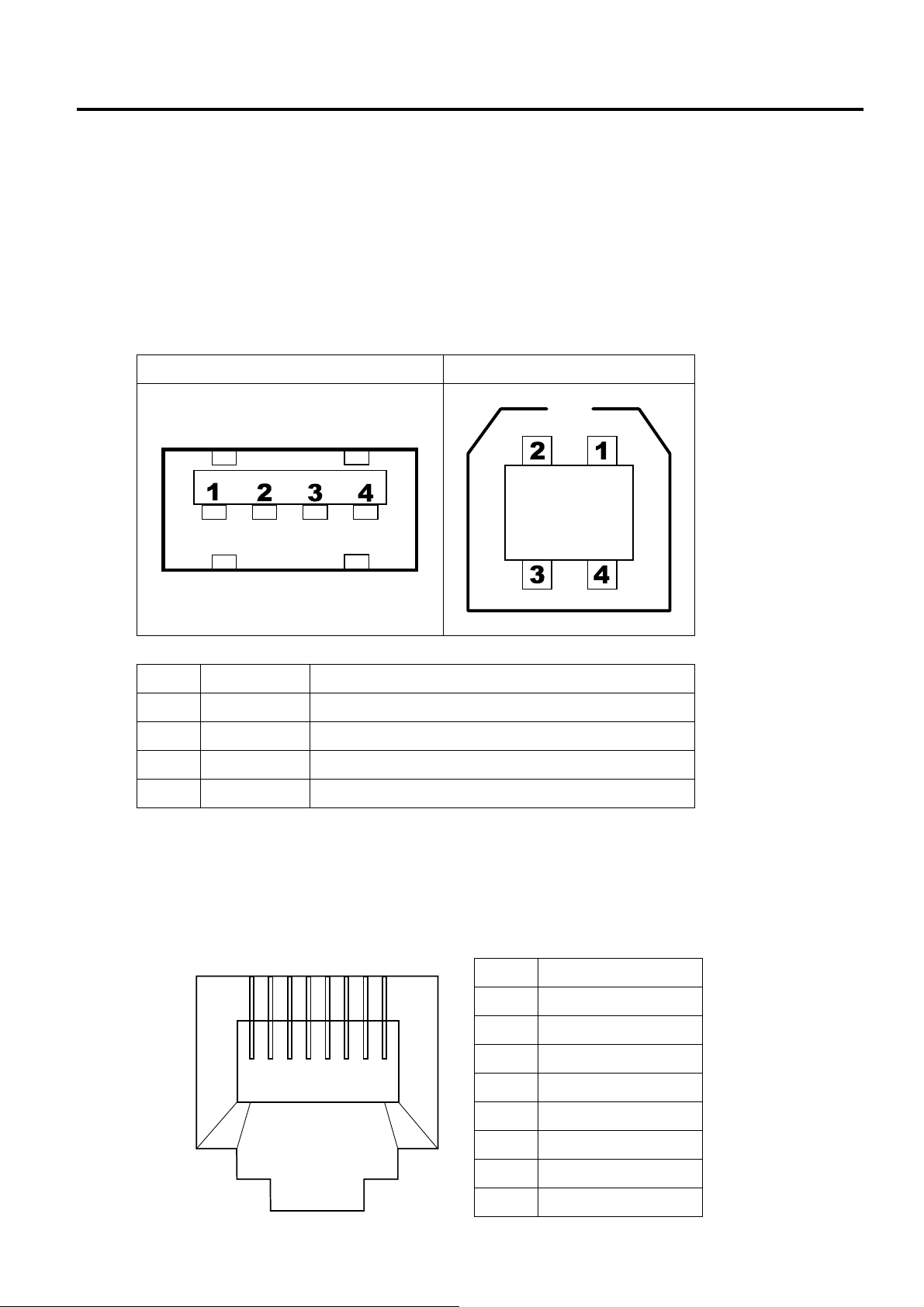
1.4.1 USB
Your printer has two USB ports: type A and type B. Typically, type A is found on computers and hubs;
type B is found on devices and hubs. The figure below shows their pinouts.
Type A Type B
Pin Signal Description
1 VBUS +5V
2 D- Differential data signaling pair 3 D+ Differential data signaling pair +
4 Ground Ground
1.4.2 Ethernet
The Ethernet uses RJ-45 cable, which is 8P8C (8-Position 8-Contact). The figure below shows its
pinout.
2
1
3456
8
7
Pin Signal
1 Transmit+
2 Transmit3 Receive+
4 Reserved
5 Reserved
6 Receive7 Reserved
8 Reserved
1-17
1. OUTLINE EO18-33030
1.4 Interface I/O Port
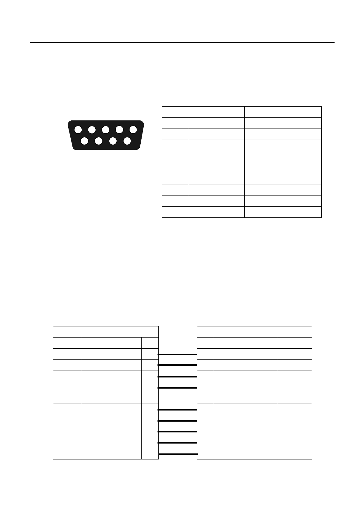
1.4.3 RS-232C
The RS-232C on your printer is DB9 female. It transmits data bit by bit in asynchronous start-stop
mode. The figure below shows its pinout.
4
3
2
1
5
7
89
6
Pin Signal Description
1 +5V Provide 5V Power
2 TxD Transmit
3 RxD Receive
4 CTS Clear to Send
5 GND Ground
6 RTS Request to Send
7 NC No Connection
8 RTS Request to Send
9 NC No Connection
Speed: 2400, 4800, 9600, 19200, 38400, 57600, 115200 Bauds
Parity: Odd, Even or None
Data Bits: 7 or 8 Bits
Stop Bits: 1 or 2 Bits
Flow Control: XON/XOFF or RTS
Default Parameters: 9600 Bauds, No Parity, 8 Data Bits, 1 Stop Bit, XON/XOFF
Host (DB9)
Signal Description Pin
CD Carrier Detect 1
RxD Receive 2 2 Transmit TxD
TxD Transmit 3 3 Receive RxD
DTR Data Terminal
Ready
GND Ground 5 5 Ground GND
DSR Data Set Ready 6 6 Request to Send RTS
RTS Request to Send 7 7 No Connection NC
CTS Clear to Send 8 8 Request to Send RTS
CI 9
4 4 Clear to Send CTS
Pin Description Signal
1 Provide 5V Power +5V
9 No Connection NC
Printer (DB9)
1-18
 Loading...