

Toshiba B-EX Series, B-EX4T1-G, B-EX4T1-T, B-EX4T2-G, B-EX6T2-G Key Operation Specification
...Page 1

TOSHIBA Bar Code Printer
B-EX Series
Key Operation Specification
First edition: April 1, 2011
2nd edition: July 7, 2011
Page 2

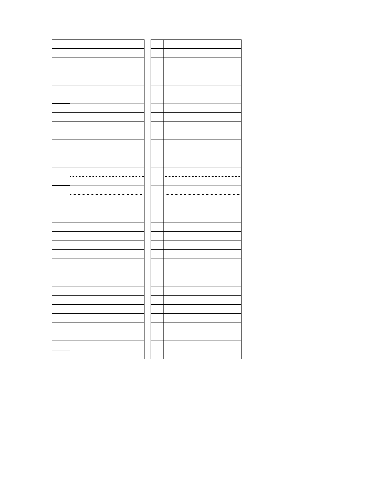
Table of Contents
Page
1 SCOPE ................................................................................................................................................1
2 OUTLINE .............................................................................................................................................1
3 OPERATION PANEL...........................................................................................................................1
4 OUTLINE OF EACH MODE.................................................................................................................2
4.1 ONLINE MODE ......................................................................................................................................2
4.1.1 Threshold setting mode ......................................................................................................................2
4.2 SYSTEM MODE.....................................................................................................................................2
4.3 USER SYSTEM MODE..........................................................................................................................2
4.4 DOWNLOAD MODE ..............................................................................................................................2
4.5 AUTO CONFIGURATION MODE ..........................................................................................................2
5 GENERAL VIEW OF KEY OPERATION.............................................................................................3
6 ONLINE MODE....................................................................................................................................4
6.1 KEY FUNCTION.....................................................................................................................................4
6.1.1 Online Mode Display ..........................................................................................................................4
6.1.2 Help Display........................................................................................................................................5
6.1.3 Manual Threshold Setting Display......................................................................................................5
6.2 LED FUNCTION.....................................................................................................................................6
6.3 LCD FUNCTION.....................................................................................................................................6
6.4 ONLINE MODE LCD DISPLAY..............................................................................................................6
6.4.1 Online Mode LCD Display Example ...................................................................................................6
6.4.2 Icon .....................................................................................................................................................8
6.4.3 Online Mode Display Transition, Operation example.........................................................................9
6.5 HELP DISPLAY....................................................................................................................................10
6.5.1 Explanation of Help Display..............................................................................................................10
6.5.2 Help Display Transition, Operation Example....................................................................................11
6.6 MANUAL THRESHOLD SETTING.......................................................................................................12
6.6.1 Outline of Threshold setting..............................................................................................................12
6.6.2 Threshold Setting Operation Example .............................................................................................13
6.7 JOB CANCELLATION..........................................................................................................................17
6.7.1 Outline of the Job Cancellation.........................................................................................................17
6.7.2 Job Cancellation Operation Example ...............................................................................................17
6.8 LCD MESSAGES AND LED INDICATIONS ........................................................................................18
7 DISPLAY PATTERN AND KEY OPERATION FOR SYSTEM MODE ANDUSER MODE ................ 25
7.1 LIST BOX WITH SCROLLBAR ............................................................................................................25
7.2 VALUE SETTING DISPLAY.................................................................................................................29
7.3 INFORMATION DISPLAY ....................................................................................................................31
7.4 SENSOR ADJUSTMENT DISPLAY.....................................................................................................33
7.5 TEMPERATURE DISPLAY ..................................................................................................................35
7.6 File Selection Display ...........................................................................................................................36
Page 3

8 SYSTEM MODE.................................................................................................................................37
8.1 OUTLINE OF SYSTEM MODE ............................................................................................................37
8.2 REFLECTING THE SYSTEM MODE SETTINGS IN THE PRINTER..................................................38
8.3 DIAG.....................................................................................................................................................39
8.3.1 MAINTENANCE CONT ....................................................................................................................39
8.3.2 AUTO DIAGNOSTIC ........................................................................................................................52
8.3.3 HEAD CHECK ..................................................................................................................................60
8.4 PARAMETER SET ...............................................................................................................................61
8.4.1 PRINTER SET..................................................................................................................................61
8.4.2 SOFTWARE SET .............................................................................................................................64
8.4.3 PANEL ..............................................................................................................................................71
8.4.4 PASSWORD.....................................................................................................................................72
8.5 ADJUST SET........................................................................................................................................74
8.5.1 FEED ADJ. .......................................................................................................................................75
8.5.2 CUT ADJ...........................................................................................................................................76
8.5.3 BACK ADJ. .......................................................................................................................................81
8.5.4 X ADJUST ........................................................................................................................................82
8.5.5 TONE ADJ. (TRANS.) ......................................................................................................................82
8.5.6 TONE ADJ. (DIRECT) ......................................................................................................................82
8.5.7 RBN ADJ.<FW>................................................................................................................................83
8.5.8 RBN ADJ.<BK> ................................................................................................................................83
8.5.9 THRESHOLD <REFL.> ....................................................................................................................83
8.5.10 THRESHOLD <TRANS.> .............................................................................................................83
8.6 TEST PRINT.........................................................................................................................................85
8.6.1 PRINT CONDITION..........................................................................................................................85
8.6.2 SLANT LINE (1DOT) ........................................................................................................................88
8.6.3 SLANT LINE (3DOT) ........................................................................................................................89
8.6.4 CHARACTERS.................................................................................................................................90
8.6.5 BARCODE ........................................................................................................................................91
8.6.6 NON-PRINTING ...............................................................................................................................91
8.6.7 FACTORY TEST ..............................................................................................................................91
8.6.8 AUTO PRINT (TRANS.) ...................................................................................................................92
8.6.9 AUTO PRINT (REFL.) ......................................................................................................................92
8.7 SENSOR ADJUST ...............................................................................................................................93
8.7.1 TEMPERATURE...............................................................................................................................93
8.7.2 REFLECT .........................................................................................................................................93
8.7.3 TRANS..............................................................................................................................................93
8.7.4 PE REFL./TRANS.............................................................................................................................94
8.7.5 RIBBON ............................................................................................................................................94
8.8 RAM CLEAR.........................................................................................................................................95
8.8.1 NO RAM CLEAR ..............................................................................................................................95
8.8.2 MAINTE.CNT CLEAR.......................................................................................................................95
8.8.3 PARAMETER CLEAR ......................................................................................................................96
8.9 INTERFACE .......................................................................................................................................102
8.9.1 NETWORK .....................................................................................................................................102
8.9.2 USB.................................................................................................................................................107
8.9.3 RS-232C .........................................................................................................................................108
8.9.4 CENTRO.........................................................................................................................................109
Page 4

8.10
BASIC.................................................................................................................................................110
8.10.1 BASIC .........................................................................................................................................110
8.10.2 FILE MAINTENANCE .................................................................................................................110
8.10.3 TRACE........................................................................................................................................110
8.10.4 EXPAND MODE .........................................................................................................................110
8.11 FOR FACTORY..................................................................................................................................111
8.11.1 HEAD UP ADJUST.....................................................................................................................111
8.11.2 PANEL TEST ..............................................................................................................................111
8.11.3 KEY TEST...................................................................................................................................112
8.12 RFID ...................................................................................................................................................114
8.12.1 TEST...........................................................................................................................................114
8.12.2 MODULE.....................................................................................................................................116
8.12.3 RETRY........................................................................................................................................117
8.12.4 UHF SETTING............................................................................................................................119
8.12.5 OTHER .......................................................................................................................................122
8.13 RTC ....................................................................................................................................................124
8.13.1 DATE TIME.................................................................................................................................124
8.13.2 BATTERY CHECK......................................................................................................................124
8.13.3 RENEWAL ..................................................................................................................................124
8.14 Z-MODE .............................................................................................................................................125
8.15 USB MEMORY...................................................................................................................................126
8.15.1 USB TO PRINTER......................................................................................................................127
8.15.2 PRINTER TO USB......................................................................................................................127
8.16 RESET................................................................................................................................................128
9 USER SYSTEM MODE....................................................................................................................129
9.1 OUTLINE OF USER SYSTEM MODE ...............................................................................................129
9.2 RESET................................................................................................................................................130
9.3 PARAMETER SET .............................................................................................................................130
9.4 ADJUST SET......................................................................................................................................130
9.5 LAN/WLAN .........................................................................................................................................131
9.5.1 LAN/WLAN .....................................................................................................................................131
9.5.2 SNMP..............................................................................................................................................131
9.6 BASIC.................................................................................................................................................132
9.7 Z-MODE .............................................................................................................................................132
9.8 AUTO CALIB ......................................................................................................................................133
9.9 DUMP MODE .....................................................................................................................................135
9.9.1 BUFFER .........................................................................................................................................135
9.9.2 DUMP LIST.....................................................................................................................................135
9.10 LOG ....................................................................................................................................................138
9.10.1 PRINTER TO USB......................................................................................................................138
10 DOWNLOAD ................................................................................................................................139
11 AUTO CONFIGURATION MODE ................................................................................................141
11.1 Outline of the Auto Configuration Mode .............................................................................................141
11.2 Preparation for USB Memory .............................................................................................................141
11.3 Auto Configuration File.......................................................................................................................142
11.3.1 Format.........................................................................................................................................142
11.3.2 Model Information .......................................................................................................................142
Page 5

11.3.3
Display Message.........................................................................................................................142
11.3.4 Firmware File to be Downloaded................................................................................................142
12 POWER SAVE FUNCTION..........................................................................................................143
Copyright © 2011
by TOSHIBA TEC CORPORATION
A
ll Rights Reserved
570 Ohito,Izunokuni-shi,Shizuoka-ken,JAPAN
Page 6

1
1 SCOPE
This specification describes key operations using the keys and the LCD display of the B-EX4T1-G and
B-EX4T1-T (hereinafter collectively referred to as “B-EX4T”) high-end industrial general-purpose bar code
printers.
2 OUTLINE
Key operations are different depending on the printer mode: Online mode, in which operations are carried out
through the keys and error messages are displayed while the printer is connected to the host such as a PC, and
the system mode, in which self-test and setting of various parameters are performed.
This specification describes the key operation procedures with the printer keys and the LCD panel.
The names of the keys and LCD messages used in this specification are written in English
3 OPERATION PANEL
Graphic LCD
ERROR LED
PAUSE key
ENTER key
RIGHT key
UP key
RESTART key
ONLINE LED
FEED key
MODE key
CANCEL key
LEFT key
DOWN key
Page 7

2
4 OUTLINE OF EACH MODE
This chapter describes the outline of each mode supported by the printer. Refer to each chapter for detailed
information.
4.1 ONLINE MODE
This mode is mainly used by users (operators).
The label or tag can be issued in the online mode. When an error occurs, the help function shows the
cause of an error, troubleshooting, and recovery from the error. The threshold setting, described below, is
also a part of the online mode.
4.1.1 Threshold setting mode
Threshold setting mode is provided to correct a print failure with pre-printed media.
When using pre-print label, detection of a print position may be disabled with the usual media sensor
threshold, depending on the ink type. Such error can be prevented by setting the threshold just for the
pre-printed media to be used. Since the threshold setting value is stored in the non-volatile memory, it is
unnecessary to set the threshold again as long as the same pre-print media is used.
4.2 SYSTEM MODE
Turning the power on while holding down the both [FEED] and [PAUSE] keys, or the [MODE] key alone
activates the system mode. This mode is mainly used by service persons or the Production Dept. for
adjustment before shipment. The system mode contains the menus which might be changed not so
frequently.
In addition to the menus common to the User System Mode, such as parameter setting, fine adjustment,
and BASIC setting, there are sensor adjustment, interface, RFID and RTC setting menus.
Furthermore, self-diagnosis, test print, RAM clear to initialize the printer settings, pre-shipment adjustment
for factory use, and the menu which enables saving parameter settings, external characters, TPCL
commands to the external USB memory or copying the data from the USB memory to the printer are
provided. The values set in this mode are stored in the non-volatile memory.
4.3 USER SYSTEM MODE
The user system mode is accessible from the online mode. This mode, mainly used by users
(administrator) or service persons, contains the menus which might be frequently changed.
In addition to the menus common to the System Mode, such as parameter setting, fine adjustment, and
BASIC setting, there are LAN/WLAN setting, auto calibration, dump function which enables the printer to
dump received data.
The values set in this mode are stored in the non-volatile memory.
4.4 DOWNLOAD MODE
This mode is used to download boot and main programs.
4.5 AUTO CONFIGURATION MODE
This mode is used to update printer firmware stored in USB memory.
Page 8
3
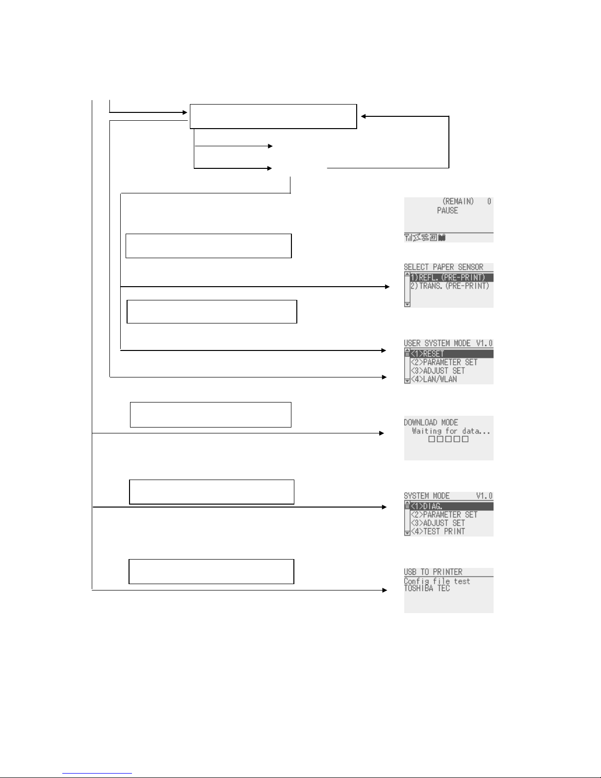
5 GENERAL VIEW OF KEY OPERATION
Display
To enter the download mode, system mode or auto configuration mode, keep holding down the key until each
display is shown.
[Power OFF]
[PAUSE] key
[RESTART] key
[FEED] key
Hold down the [PAUSE] key for a few
seconds.
Hold down the [RESTART] o
r
[MODE] key for a few seconds.
Power on
Turn the power on while holding down the
[FEED] and [PAUSE] keys at the same time o
r
holding down the [MODE] keys.
Threshold setting mode
User mode
Download mode
System mode
Online mode
[Online]
[Feeds one label]
[Pause]
Hold down the [MODE] key for a
few seconds.
Turn the power on while holding down the
[CANCEL] key.
A
uto configuration mode
Turn the power on while holding down the
[FEED], [RESTART] and [PAUSE] keys.
Page 9

4
6 ONLINE MODE
6.1 KEY FUNCTION
The printer behavior is not guaranteed when undefined key is operated.
6.1.1 Online Mode Display
Key Function
(1) Feeds one piece of media.
Ejects one piece of media.
Used to adjust the media to the proper position. If printing is attempted with the
media improperly positioned, printing is not performed at the proper position. One or
two pieces of media need to be fed to adjust the paper position before printing.
(2) Prints the data in the image buffer on one piece of media according to the system
mode setting.
NOTE: A Clear Command or a command for drawing shall not be sent while printing
caused by a depression of the [FEED] key. If it is sent, the layout will be destroyed,
and the media will not be printed properly. Also, if printing is performed by a
depression of the [FEED] key while the data is being drawn in the image buffer, the
layout may be destroyed.
* For details of the following cases, refer to the parameter setting section.
• How to issue the label stock having the label pitch of 25.4 mm or less in the cut issue
mode when the disc cutter is used.
• How to issue the label stock having the minimum label pitch or less for each print
speed in the cut issue mode when the rotary cutter is used.
* In the strip mode, feeds labels even when the peel-off sensor is detecting a label.
[FEED]
* When Media Load parameter is enabled, a media feed is performed to find the print
start position depending on the condition. For details, refer to Section 8.4.1.1 MEDIA
LOAD.
(1) Resumes printing after a temporary stop of printing or after an error.
(2) Places the printer in the usual initial state, which is obtained when the power is turned
on.
[RESTART]
(3) Places the printer in the user system mode.
(1) Stops label printing temporarily. [PAUSE]
(2) Programs the threshold value.
[MODE] (1) Places the printer in the user system mode.
[CANCEL] (1) Clears the job.
[ENTER] (1) Displays help messages.
[UP] (1) No function.
[DOWN] (1) No function.
[LEFT] (1) No function.
[RIGHT] (1) Displays help messages.
Page 10

5
6.1.2 Help Display
Key Function
[FEED] (1) Ends help display.
[RESTART] (1) Ends help display.
[PAUSE] (1) Ends help display.
[MODE] (1) Ends help display.
(1) Ends help display.
(2) Returns to the previous help page.
[CANCEL]
(3) Ends help display.
(1) Ends help display.
(2) Goes to the next help page.
[ENTER]
(3) Ends help display.
[UP] (1) Moves the cursor upward.
[DOWN] (1) Moves the cursor downward.
(1) Returns to the previous help page. [LEFT]
(2) Ends help display.
(1) Goes to the next help page. [RIGHT]
(2) Ends help display.
6.1.3 Manual Threshold Setting Display
Key Function
(1) Moves the cursor upward.
[FEED]
(2) Re-sets
[RESTART] (1) Moves the cursor downward.
(1) Sets the threshold. [PAUSE]
(2) Fixes the selection.
[MODE] No function.
[CANCEL] No function.
(1) Fixes the selection. [ENTER]
(2) Ends manual threshold setting.
[UP] (1) Moves the cursor upward.
[DOWN] (1) Moves the cursor downward.
(1) Goes to the judgment result page [LEFT]
(2) Goes to the fine adjustment setting menu
(1) Goes to the detail page. [RIGHT]
(2) Goes to the fine adjustment setting menu
Page 11
6
6.2 LED FUNCTION
Indicates that the printer is in online state.
Flashes when the printer is communicating with the host.
[ONLINE] LED
Flashes at a 500-msec. interval (ON: 250ms., OFF: 250ms) in synchronization
with the [ERROR] LED when the printer is turned off.
Indicates that the printer is in error state.
Flashes when a ribbon near end condition is detected.
Flashes when a system error occurs (at a 1-second interval (ON: 500 ms., OFF:
500 ms.)
[ERROR] LED
Flashes at a 500-msec. interval (ON: 250ms., OFF: 250ms) in synchronization
with the [ONLINE] LED when the printer is turned off.
NOTE: If the wireless LAN is being linked at power off time, both [ONLINE] and [ERROR] LEDs turn on, not
flash.
6.3 LCD FUNCTION
The LCD displays the messages which indicate the printer status.
Type Graphics LCD
Size 128 dots (W) X 64 dots (H)
LCD
Display structure Maximum of 21 digits x 5 lines
6.4 ONLINE MODE LCD DISPLAY
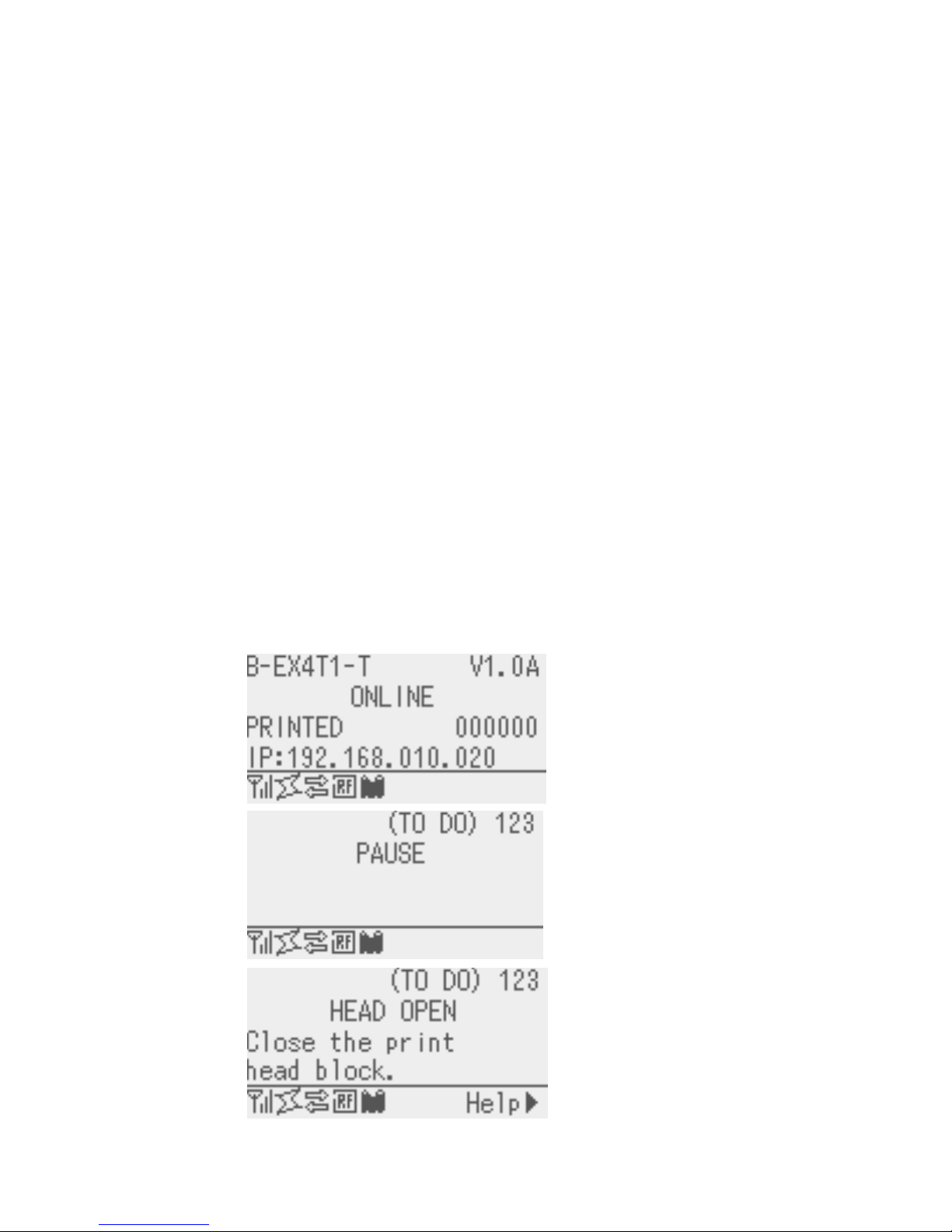
6.4.1 Online Mode LCD Display Example
Printer
condition
LCD Display Display contents
← Model name, Firmware version (*5)
← Message
← The number of labels printed (*1)
← IP address etc. (*4)
Online
← Icon
← The number of remaining labels to print (*2)
← Message
← 1
st
line of the error message
← 2
nd
line of the error message (*6)
Pause
← Icon
← The number of remaining labels to print (*2)
← Message
← 1
st
line of the error message
← 2
nd
line of the error message
Head open
← Icon, Help guide (*3)
Page 12

7
* Whether to display or hide the 1
st
, 3rd and 4th lines of online mode display can be selected in the system
mode.
* Refer to “Icon display” for Icon in detail.
(*1) The number of labels printed is the cumulative number of labels printed while the printer is activated. It is
reset to zero when the printer is turned on. During an issue with the cut interval specified, the number of
labels is updated when the label is cut normally.
(*2) [The number of remaining labels to print] = [Specified number of labels to print] – [The number of normally
printed labels before occurrence of an error or placing the printer in pause]
When the number of remaining labels to print is zero, it is not displayed. During an issue with the cut
interval specified, the number of remaining labels is updated when the label is cut normally.
(*3) The help guide is displayed only when applicable help message exists.
(*4) The message displayed in this area is IP address or supplemental information like ribbon near end.
• When LAN/WLAN setting is disabled, the IP address is not displayed even if displaying IP address is
enabled in the system mode.
• The ribbon near end message is displayed when a ribbon near end is detected, regardless of whether or
not displaying the ribbon near end message is enabled in system mode.
A ribbon near end is detected depending on diameter of the unused ribbon. The diameter of 38mm is
equivalent to 30-meter ribbon and the diameter of 43 mm is equivalent to 70-meter ribbon, respectively.
(*5) The model name description
B-EX
4 T 1 – T
Head resolution G: 203dpi, T: 305dpi, H: 600dpi
Type 1: Type1, 2: Type2
Print method T: Thermal transfer/Direct thermal
Print width 4: 4” width, 6: 6” width
Series model
(*6) The ribbon near end message may be displayed on this line. The condition for display is the same as *4.
Page 13

8
6.4.2 Icon
Five kinds of icon are displayed in the bottom line of the online mode display.
These icons are displayed only in the online mode display.
Icon Explanation
Displayed and used when the wireless LAN module is mounted.
The graph shows the strength of radio wave.
Graph 0: Outside the communication range
Graph 1: Strength of radio wave is weak.
Graph 2: Strength of radio wave is middle
Wireless LAN icon
Graph 3: Strength of radio wave is strong
Displayed and used when the wireless LAN module is mounted.
Displayed while the printer is communicating by wireless LAN.
Blinks while roaming.
OFF: No connection
ON: Connecting to an access point
Link icon
Blink: Roaming (*4)
Appears when a print job is present. Data transmission icon
ON: Print job is present.
Displayed and used when the RFID module is mounted.
Appears when a communication between the printer and the RFID
module is enabled.
Blinks during a communication with the RFID module.
- The communication includes the one without radio wave output.
- Blinks after radio wave output is instructed to the module even when no
radio wave is output.
(Blinks while the module stops outputting radio wave or changing the
channel under the influence of other carrier.)
ON: Module type is set and ready to communicate
RFID icon
⇔ Blink: Communicating
Ribbon near end is detected.
Blinks when the ribbon is close to the end.
Ribbon near end is detected depending on the diameter of unused
ribbon. ∅38 mm is equivalent to 30-meter ribbon and ∅43 mm is
equivalent to 70-meter ribbon.
Ribbon near end icon
Blinking: Ribbon near end state (*4)
(*4) Icon blinks at 1-second interval (ON for 500 msec. and OFF for 500 msec.)
Page 14
9
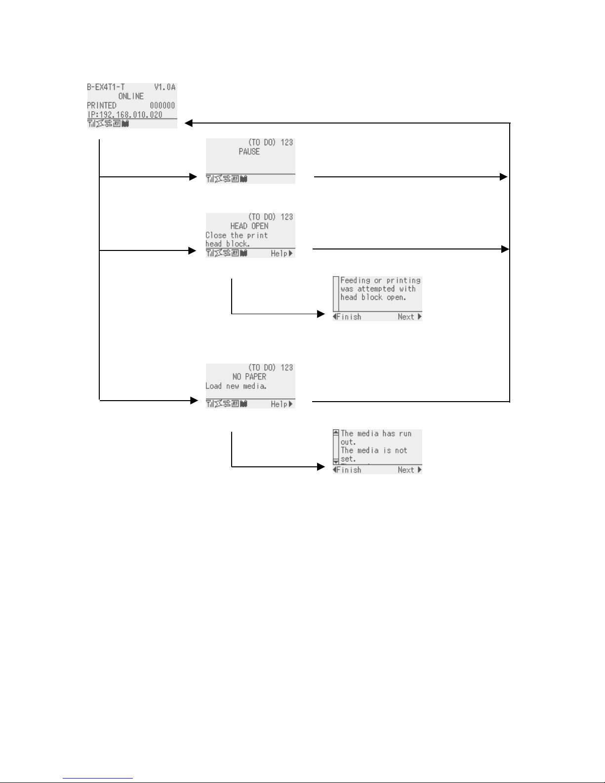
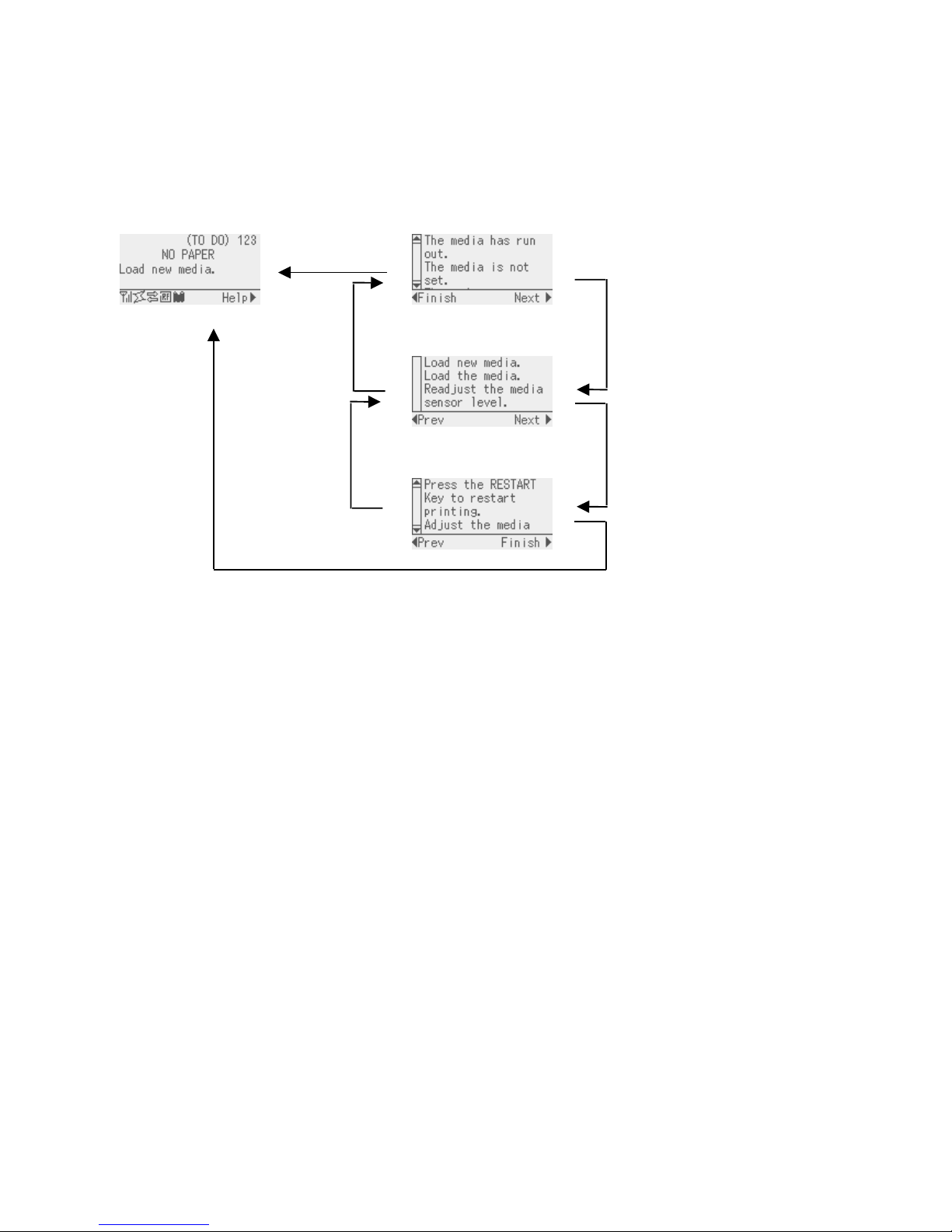
6.4.3 Online Mode Display Transition, Operation example
Idling or normal issuing
Printing is stopped
Help guide is displayed.
Help guide message for head open
(*1)
Printing is stopped and Help
guide is displayed.
Help message for NO PAPER (*1)
(*1) Refer “HELP DISPLAY TRANSITION, OPERATION EXAMPLE” for help display.
If the print head is
opened while idling
If an error occurs
while printing
When [PAUSE] key is
pressed while printing
When [RESTART] key is pressed, the
printer resumes printing if there is
remaining data
Close the print head.
Load media.
When [RESTART] key is pressed, the
printer resumes printing if there is
remaining data.
Press [RIGHT] key.
Press [RIGHT] key.
Page 15
10
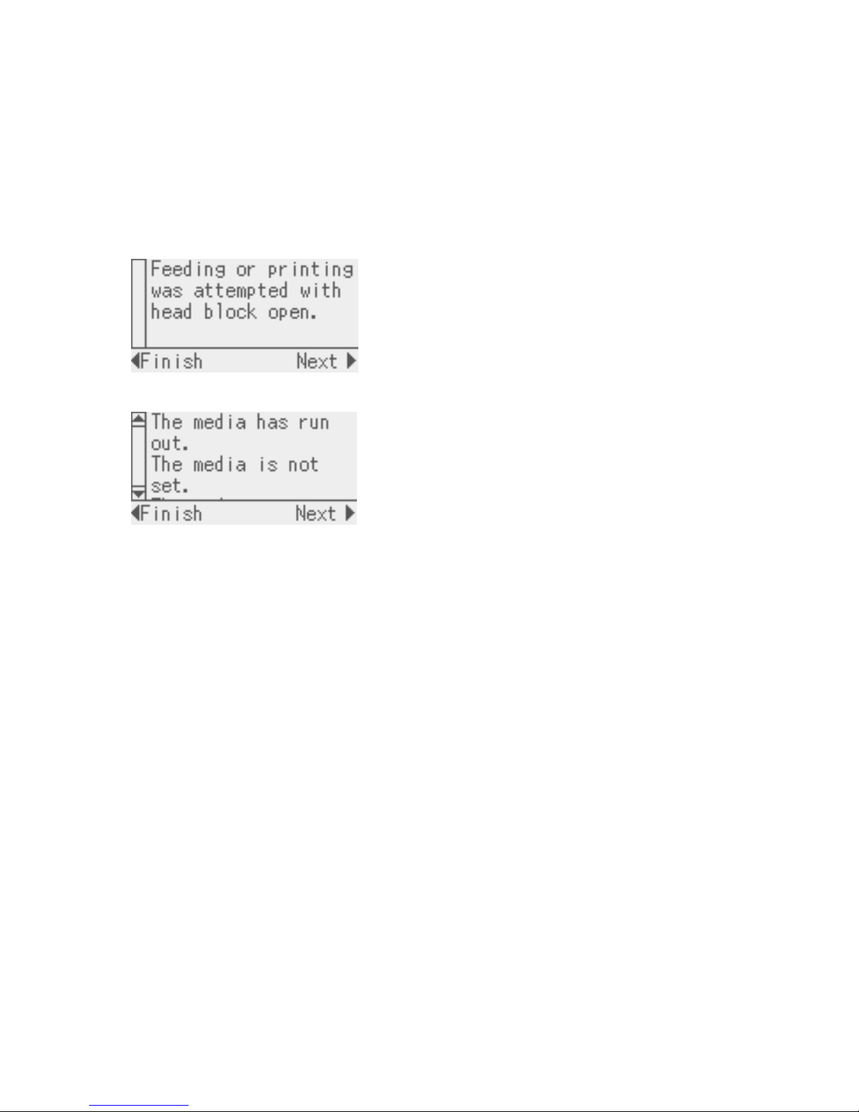
6.5 HELP DISPLAY
6.5.1 Explanation of Help Display
When “Help” is displayed at the lower right of the online mode display, pressing [RIGHT] or [ENTER] key
causes the help message to be shown.
Help message is displayed on the upper four lines. When the message exceeds four lines, the hidden lines
can be displayed by scrolling down. When scrolling is possible, the up and down arrows are provided on the
scrollbar on the left.
Display example:
← 1
st
line of help message
← 2
nd
line of help message
← 3
rd
line of help message
← 4
th
line of help message
← Help guide
Since the help message is within three lines, the scroll bar is not provided with up and down
arrows.
← 1
st
line of help message
← 2
nd
line of help message
← 3
rd
line of help message
← 4
th
line of help message
← Help guide
Since the help message exceeds four lines, the scroll bar is provided with the up and down
arrows.
Page 16
11
6.5.2 Help Display Transition, Operation Example
The help consists of three pages, which are Help1, Help2 and Help3.
Help1 shows the detail of the error, Help2 shows a troubleshooting, and Help3 shows how to recover from the
error.
Display transition
[LEFT] key
[CANCEL] key
Display transition
[RIGHT] key
[ENTER] key
Online mode Error detail
Scroll the display
with the [UP] or
[DOWN] key.
Troubleshooting
Scroll the display
with the [UP] or
[DOWN] key.
How to recover from error
Scroll the display
with the [UP] or
[DOWN] key.
(*5) When a key other than above is pressed, the help display is ended and returned to the online m
ode display.
Page 17

12
6.6 MANUAL THRESHOLD SETTING
6.6.1 Outline of Threshold setting
When a label stock is printed, the printer automatically corrects the print position by detecting gaps between
the labels using the transmissive sensor to maintain a constant print position. However, when a preprinted
label is used, some ink may prevent proper gap detection. In this case, it is required to manually program
the transmissive sensor threshold through key operations and store the value in the non-volatile memory.
Selecting “3: Transmissive Sensor (when using the preprinted label)” for the sensor type of the Issue
Command enables printing at a constant print position.
When the media with black marks printed on the back side is used, the printer automatically corrects the
print position by detecting the black marks by using the reflective sensor. However, if there is reflective
rate variation at a portion other than the black mark, the print position cannot be corrected properly. In this
case, it is required to manually program the reflective sensor threshold through key operations and store the
value in the non-volatile memory.
Selecting “4: Reflective Sensor (when using a manual threshold value)” for the sensor type of the Issue
Command enables printing at a constant print position.
Page 18
13
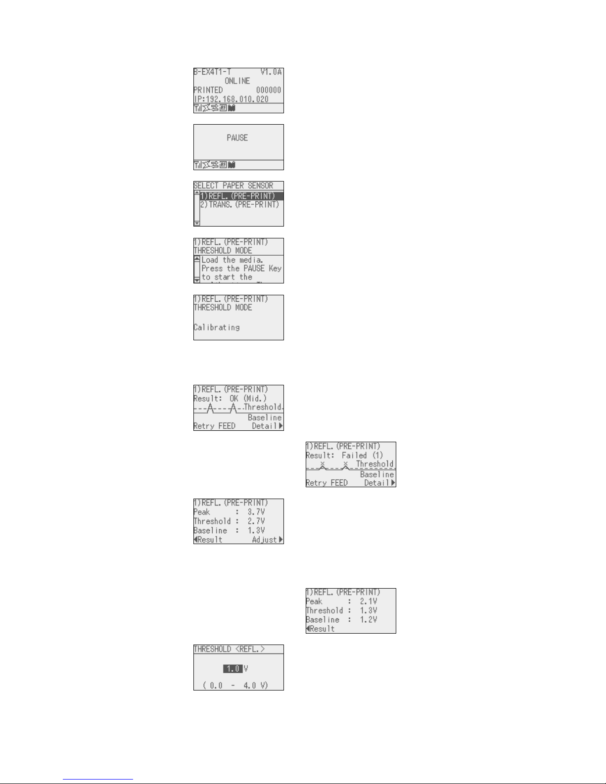
6.6.2 Threshold Setting Operation Example
[Online mode]
1. Normal state
↓ Press [PAUSE] key
[Online mode]
2. Pause state
↓ Hold down [PAUSE] key for 3 seconds
[Threshold setting]
3.
Media sensor
selection
Move the cursor with the
[UP] or [DOWN] key
↓ Press [ENTER] key
[Threshold setting]
4.
Waiting for the
media to be loaded
Scroll the display with the
[UP] or [DOWN] key
↓ Press [PAUSE] key
[Threshold setting]
5. Calibration
Hold down the [PAUSE]
key to keep feeding the
media
↓ Release [PAUSE] key. When the [PAUSE] key is
released, media feed
stops
↓ ↓
[Threshold setting]
6a.
Result: OK (Mid.)
↓
↓
↓
↓
↓ ↓
[Threshold setting]
6b.
Result: NG (1)
↓
↓
↓
Pressing the [FEED] key
returns the display to “3.
Media sensor selection.”
Pressing the [ENTER] key
returns the display to “2.
Pause condition.”
Pressing the [RIGHT] key
causes the display to go
to “7a/7b. Detail.
↓ Press [RIGHT] key ↓
[Threshold setting]
7a.
Detail: OK (Mid.)
↓
↓
↓
↓
↓
↓
Pressing the [RIGHT] key
causes the display to go
to “8a. Sensor Fine
adjustment.”
Pressing the [LEFT] key
returns the display to “6a.
Judgment.”
↓ ↓
[Threshold setting]
7b.
Detail: NG (1)
↓
↓
↓
Pressing the [LEFT] key
returns the display to “6b.
Judgment
↓ Press [RIGHT] key
[Threshold setting]
8a. Sensor fine
adjustment
Operation is same as 8.5.9
reflective sensor fine
adjustment
Pressing the [PAUSE],
[ENTER] or [CANCEL]
key returns the display to
“6a. Judgment
Page 19
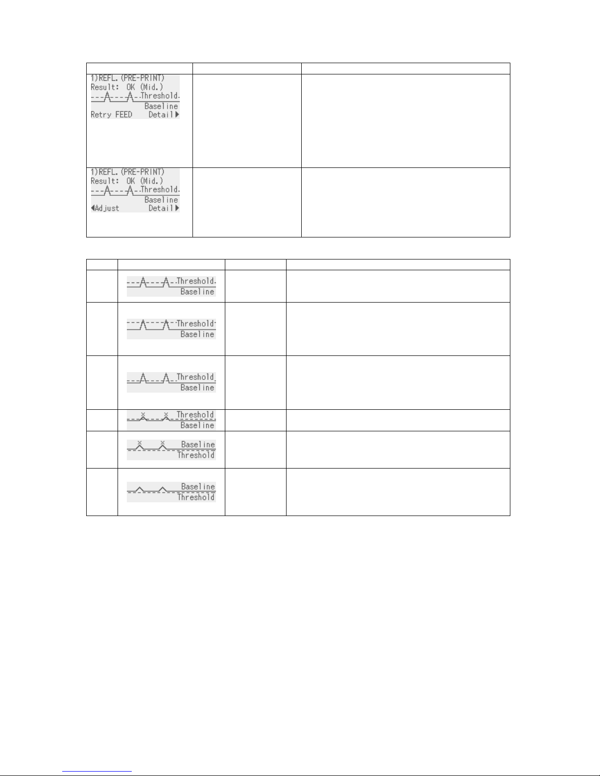
14
Judgment result
Display example Displayed item Explanation
• Sensor type
• Result (Text)
• Result (Graph)
• Key operation guide
The calibration result is shown.
Pressing the [FEED] key returns the display to
the media sensor selection and enables a
threshold setting.
Pressing the [RIGHT] key shows the measured
voltages.
Pressing the [ENTER] key terminates the
threshold setting.
• Sensor type
• Result (Text)
• Result (Graph)
• Key operation guide
The result of fine adjusted threshold setting is
shown.
Pressing the [LEFT] key returns the display to
the threshold fine adjustment.
The [RIGHT] and [ENTER] keys function in the
same way as above.
The threshold setting result is indicated with one of the following icon types.
No. Display example Icon name Explanation
1
OK (Mid.) Print position is detectable with the media sensor.
Threshold is at the midpoint between the peak and
the baseline.
2
OK (High) Threshold is near the peak voltage, so detection of
a gap/black mark may fail if the voltage difference is
very small. (Adjusting the threshold to the midpoint
between the peak and the baseline enables more
accurate detection.)
3
OK (Low) Threshold is near the baseline voltage, so detection
of a gap/black mark may fail if the voltage difference
is very small. (Adjusting the threshold to the
midpoint between the peak and the baseline
enables more accurate detection.)
4
NG (1)
Print position is not detectable with the media
sensor. Sensor adjustment is necessary.
5
NG (1)
Print position is not detectable with the media
sensor. Sensor adjustment is necessary.
(Threshold ≤ Baseline)
6
NG (2)
Print position is not detectable with the media
sensor.
(Calibration may enable print position detection,
but it is very difficult.)
Page 20

15
Detailed display
Display example Displayed item Explanation
• Sensor type
• Peak value
• Threshold voltage
• Baseline voltage
• Key operation guid
e
The calibration result and the threshold voltage
are displayed.
Pressing the [RIGHT] key enables setting a
threshold fine adjustment value.
Pressing the [LEFT] key returns the display to the
calibration result display.
(Supplementary Explanation)
(1) When the [PAUSE] key is released within 3 seconds while the printer is paused, the [PAUSE] key is
invalid.
(2) To program the threshold, 1.5 pieces or more label shall be fed. (If the label feed amount is insufficient,
the threshold may not be properly programmed. In this case, the threshold setting is required again.)
(3) While the head is lifted, the [PAUSE] key is invalid even if the [PAUSE] key is held down for 3 seconds or
more.
(4) When the proper print position is not obtained even after threshold setting, the sensor may be improperly
adjusted. In this case, readjust the sensor in system mode, and program the threshold.
When the backing paper of the label is too thick, the transmissive sensor needs to be readjusted.
In addition, make sure that “3: Transmissive sensor (when using the preprinted label)” or “4: Reflective
sensor (when using a manual threshold value)” is selected for sensor type of the Feed Command and
the Issue Command.
(5) Paper end and ribbon end are not detectable during the threshold setting. (The setting continues as long
as the [PAUSE] key is held down even if the printer runs short of media or ribbon.)
(6) The detailed display is shown when the [RIGHT] key is pressed while the result is displayed. The
measured sensor level and the currently programmed threshold fine adjustment value can be checked.
Fine adjustment value = Peak voltage – Threshold voltage
(7) Pressing the [LEFT] key returns the detailed display to the result display. Pressing the [RIGHT] key
causes the display to go to threshold fine adjustment screen. This is the same menu with the threshold
fine adjustment menu in section 8.5.9 (Reflective sensor) or 8.5.10 (Transmissive sensor).
(8) After setting the threshold fine adjustment value, the screen returns to the result display.
(9) While the result of fine adjusted threshold setting is shown, pressing the [LEFT] key returns the display to
the threshold fine adjustment screen and pressing the [RIGHT] key goes to the detailed display.
(10) During threshold setting, the media is fed at the same speed with that for the previous issue.
(11) Whether the threshold setting succeeded or not can be checked with either of the following methods.
Media feed with the [FEED] key
1. While the judgment result is displayed, press the [FEED] key to terminate the threshold setting.
→ The printer is placed in the pause state.
2. Press the [RESTART] key to clear the pause state.
→ The printer is placed in the online state.
3. Hold down the [MODE] key.
→ The printer enters the user system mode.
4. Select “<2>PARAMETER SET”, “Software Set”, then “THRESHOLD SELECT” with the [UP], [DOWN]
and [ENTER] keys.
5. Select the applicable media sensor type (“REFLECT” or “TRANS.”) and press the [ENTER] key.
→ The selected sensor type display is shown.
6. Select “MANUAL SET”, press the [ENTER] key, then [MODE] key.
→ User system mode menu is displayed.
Page 21

16
7. Select “<1> RESET” and press the [ENTER] key.
→ After the printer is reset, it is placed in the online mode.
8. Press the [FEED] key to feed the media.
→ If a paper jam occurs or the media does not stop at the print start position, retry the threshold setting.
Sending Issue command
1. Press the [FEED] key while the judgment result is displayed to terminate the threshold setting.
→ The printer is placed in the pause state.
2. Press the [RESTART] key to clear the pause state.
→ The printer is placed in the online state.
3. Hold down the [MODE] key.
→ The printer enters the user system mode.
4. Select “<2>PARAMETER SET”, “Software Set”, then “THRESHOLD SELECT” with the [UP], [DOWN]
and [ENTER] keys.
5. Select the media sensor type (“REFLECT” or “TRANS.”) depending on the sensor type specified by the
Issue Command, and press the [ENTER] key.
Sensor type in Issue Command Setting
0: No sensor Whether the threshold setting succeeded or not cannot be
checked.
1: Reflective sensor Select “REFLECT”.
When the selected sensor type display is shown, select
“MANUAL SET” and press the [ENTER] key.
* Select the media sensor type to the one for which the
threshold was set.
2: Transmissive sensor (when using
normal labels)
Select “TRANS.”
When the selected sensor type display is shown, select
“MANUAL SET” and press the [ENTER] key.
* Select the media sensor type to the one for which the
threshold was set.
3: Transmissive sensor (when using
preprinted labels)
No setting is necessary.
4: Reflective sensor (when using a
manual threshold value)
No setting is necessary.
6. Press the [MODE] key.
→ User system mode menu is displayed.
7. Select “<1> RESET” and press the [ENTER] key.
→ After the printer is reset, it is placed in the online mode.
8. Send an Issue Command to make the printer print.
→ If a paper jam occurs or the media does not stop at the print start position, retry the threshold setting.
Page 22
17
6.7 JOB CANCELLATION
6.7.1 Outline of the Job Cancellation
The [CANCEL] key enables cancellation of subsequent print jobs.
Holding down the [CANCEL] key for 3 seconds while the printer is in an error* or pause state causes the
printer to start a quick reset and shift to the online mode.
As long as the [CANCEL] key is held down, the data in the receive buffer is all discarded.
Job cancellation is finished when the [CANCEL] key is released, and the printer restores to the normal
condition.
*: Errors which can be recovered by a depression of the [RESTART] key.
For details, refer to Section 6.8 LCD MESSAGES AND LED INDICATIONS.
*: A command error may occur if the [CENCEL] key is released before the all received data has been
discarded.
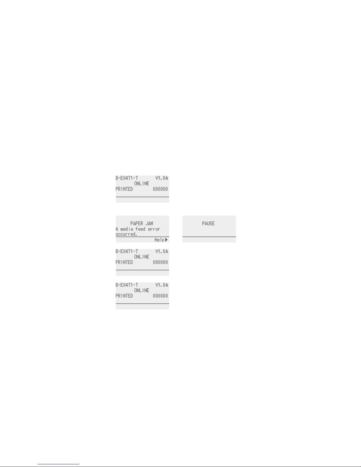
6.7.2 Job Cancellation Operation Example
[Online mode]
1. Normal condition
↓ Occurrence of an error of depression of the
[PAUSE] key.
[Online mode]
2. Pause or error
condition
↓ Hold down [PAUSE] key for 3 seconds.
[Online mode]
3. Job cancellation
after quick reset
As long as the [CANCEL]
key is held down, received
data is discarded.
↓ Release the [CALCEL] key.
[Online mode]
4. Normal condition
The printer restores to the
online mode.
Page 23
18
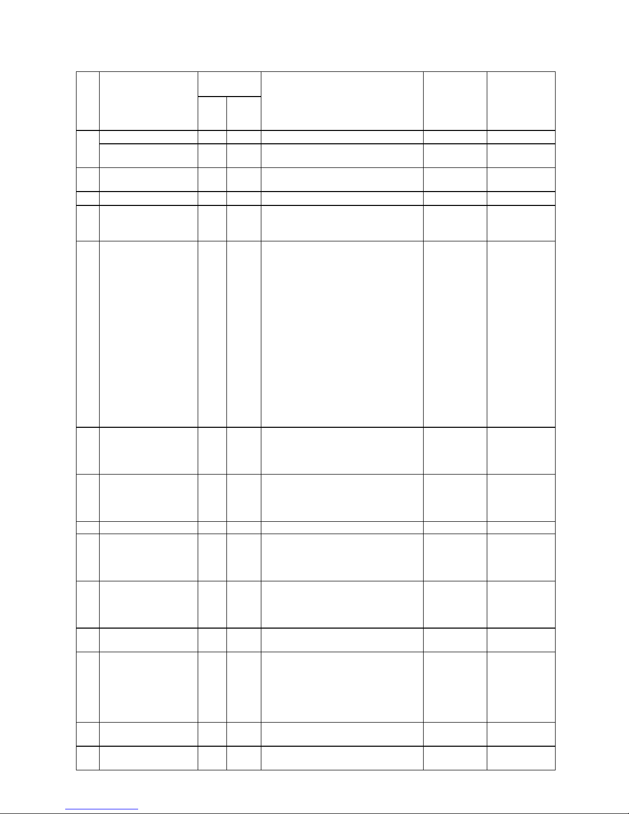
6.8 LCD MESSAGES AND LED INDICATIONS
LED
indications
No
LCD Message
2
nd
line
(English)
ON
LINE
ERROR
Printer status
Restoration by
the [RESTART]
key
Yes/No
Acceptance of
Status Request
and Reset
Command
Yes/No
ONLINE ○ ●
In the online mode
-
Yes
1
ONLINE
●
In the online mode
(Communicating)
-
Yes
2 HEAD OPEN ● ●
A feed or an issue was attempted
with the head opened.
-
Yes
3 PAUSE ● ●
In a pause state
Yes Yes
4 COMMS ERROR ●
A parity error or framing error has
occurred during communication by
RS-232C.
Yes Yes
5 PAPER JAM ●
A paper jam occurred during paper
feed.
Paper was not set properly.
Label actually used and the
selected media sensor type do not
match.
The media sensor position does
not align with the black mark
position.
The actual media size and the
specified media length do not
match.
The level of media sensor is not
suitable for the actual media.
The gap of label cannot be
detected due to pre-printing.
Yes Yes
6 CUTTER ERROR ●
A paper jam occurred in the cutter.
The cutter did not move from the
home position.
The cutter cover was open.
Yes Yes
7 NO PAPER ●
The media has run out.
The media has not been set.
Media sensor level is not suitable
for the paper used.
Yes Yes
8 NO RIBBON ●
The ribbon has run out. Yes Yes
9 HEAD OPEN ●
A feed or an issue was attempted
with the head opened.
(Except media feed caused by the
[FEED] key or Expansion I/O)
Yes Yes
10 HEAD ERROR ●
A broken dot error has occurred in
the thermal head.
The error has occurred in the head
driver.
Yes Yes
11
EXCESS HEAD
TEMP
●
The thermal head temperature has
become excessively high.
No Yes
12 RIBBON ERROR ●
An abnormal condition occurred
with the sensor for determining the
torque of the ribbon motor.
A ribbon jam occurred.
The ribbon has been torn.
The ribbon has not been set.
Yes Yes
13 REWIND FULL ●
An overflow error has occurred in
the rewinder unit.
Yes Yes
14
SAVING ####KB/&&&&KB
or
●
Writable characters or PC
command save mode.
-
Yes
Page 24

19
SAVING %,%%%.%%%KB
15
FORMAT ####KB/&&&&KB
or
FORMAT %,%%%.%%%KB
●
Initializing the storage area.
-
Yes
16 NOW LOADING…
●
Downloading TrueType font or
BASIC program
-
Yes
17
MEMORY WRITE
ERR.
●
An error has occurred while writing
data into the memory for storage.
(USB memory, flash ROM on the
CPU board)
No Yes
18 FORMAT ERROR ●
An erase error has occurred while
formatting the memory for storage
(USB memory, flash Rom on the
CPU board)
No Yes
19 MEMORY FULL ●
Saving failed because of the
insufficient capacity of the memory
for storage (USB memory, flash
ROM on the CPU board)
No Yes
20
SYNTAX ERROR
Command error
(Refer *1, *2)
●
A command error has occurred
while analyzing the command. Yes Yes
21 POWER FAILURE ●
A momentary power interruption
has occurred.
No No
22 EEPROM ERROR ●
A backup EEPROM cannot be
read/write pr.
No No
23 SYSTEM ERROR ●
When any abnormal operations as
below are performed, a system error
occurs.
(a) Command fetch from an odd
address
(b) Access to the word data from a
place other than the boundary of
the word data
(c) Access to the long word data from
a place other than the boundary of
the long word data
(d) Access to the area of 80000000H
to FFFFFFFFH in the logic space
in the user system mode.
(e) Undefined command placed in
other than the delay slot has been
decoded.
(f) Undefined command in the delay
slot has been decoded.
(g)
Command to rewrite the delay
slot has been decoded.
No No
24 DHCP CLIENT INIT… ● ●
Initializing DHCP CLIENT.
* Only when DHCP is enabled
- -
25
RFID WRITE
ERROR
●
The printer did not succeed in
writing data onto the RFID tag after
having retried for the specified
times.
Yes Yes
26
RFID ERROR
●
The printer cannot communicate
with the RFID module.
No Yes
27 INPUT PASSWORD ● ●
The printer is waiting for a
password to be entered.
No No
28
PASSWORD
INVALID
● ●
A wrong password was entered
consecutively for three times.
No No
Page 25

20
29 RFID CONFIG ERR ●
B-EX700-RFID-U2-EU/US-R only
RFID module’s destination code is
not specified.
No No
30
LOW BATTERY
(Refer to *4,5)
●
RTC battery is low.
No Yes
31
INTERNAL COM
ERR
● ●
A hardware error has occurred in
the internal serial interface.
No No
Explanation of symbols
Symbol Explanation Range
: ON
-
: Blinking
-
: OFF
-
%%,%%%,%%%: Remaining memory size of the external USB
memory
0 to 09,999,999 (Kbyte)
####: Remaining memory size for PC command
storage area in the internal memory
0 to 3072 (Kbyte)
&&&&: Remaining memory size for writable
character storage area
0 to 3147 (Kbyte)
Page 26
21
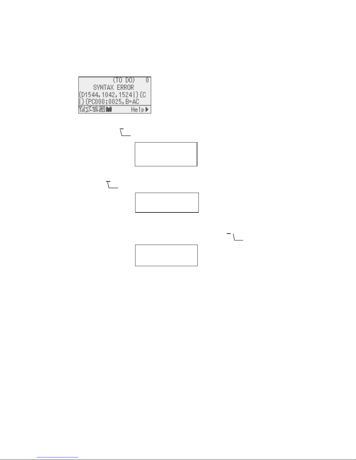
(*1) When there is command error in received command, up to 42 bytes of error command, starting from the
command code, are shown on 3
rd
and 4th lines of the LCD.
(However, [LF] and [NUL] are not displayed. Also, 43rd bytes and later are not displayed.)
Display example
(Example 1)
[ESC] PC001;0A
00,0300,2,2,A,00,B [LF][NUL]
LCD Display
(Example 2)
[ESC]T20G
30[LF][NUL]
LCD Display
(Example 3)
[ESC] PC002;0100,0300,15,15,A,00,00,J0101,+000000000A
,Z10,P1[LF][NUL]
LCD display
(*2) When a command error is displayed, the code other than 20H - 7FH and A0H - DFH is displayed as “?”
(3FH).
(*3) When the ribbon near end detection is enabled, the error LED blinks at 1-second interval (ON for 500
msec. OFF for 500 msec.) while the printer is in a ribbon near end state and displays message number 1,
2 or 3.
(*4) The battery check does not work when the printer is being reset and the RTC is not mounted.
(*5) It is necessary to follow the procedure below to use RTC function under a low battery condition.
Turn off the printer power while the printer is in an error state. Start the printer in the system mode,
set the date and time for the RTC again, then reset the printer to place the printer in online state.
* The printer can print the programmed date and time until it is turned off.
Command error
PC001;0A00,0300,2,2,A
,00,B
Command Error
T20G30
Command error
PC002;0100,0300,15,15
,A,00,00,J0101,+00000
Command error
Command error
Page 27
22
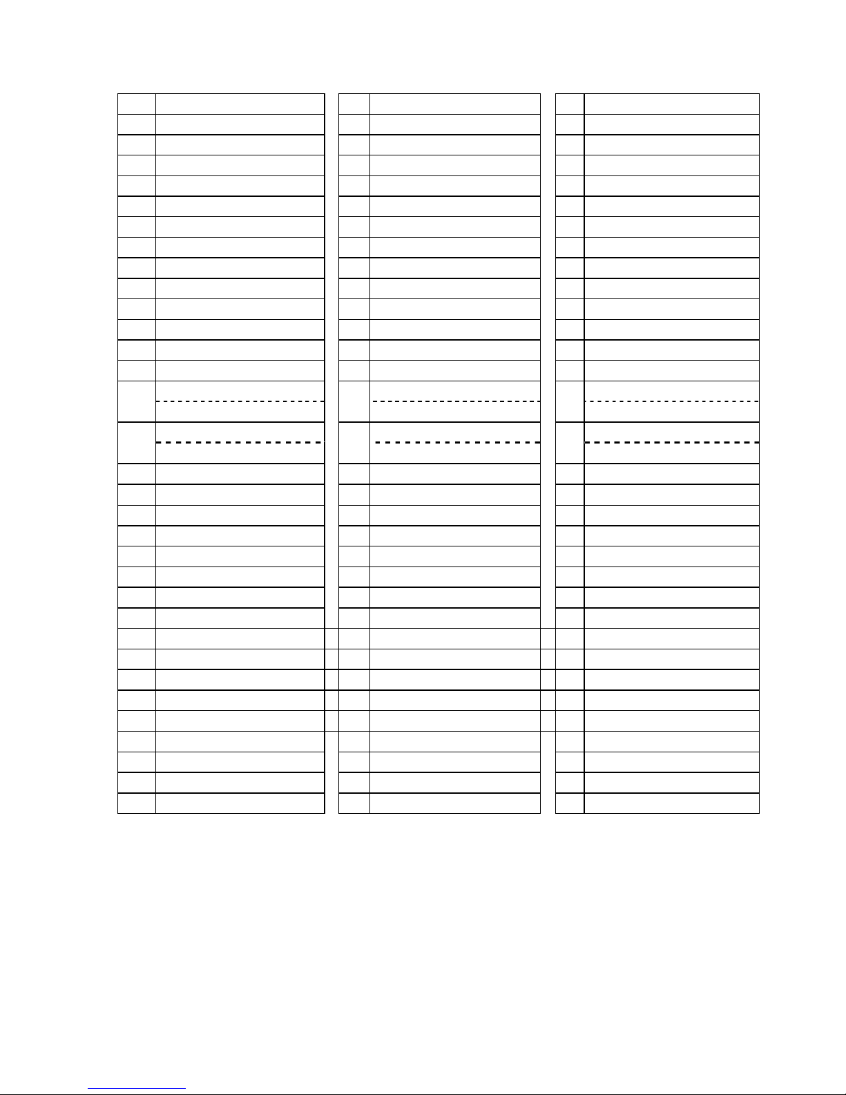
LCD message (2
nd
line)
No English No German No French
1 ONLINE 1 ONLINE 1 PRETE
2 HEAD OPEN 2 Kopf offen. 2 TÊTE OUVERTE
3 PAUSE 3 PAUSE 3 PAUSE
4 COMMS ERROR 4 Kommunikations-Fehler 4 ERREURS DE COMMUNICAT
5 PAPER JAM 5 PAPIERSTAU 5 BOURRAGE PAPIER
6 CUTTER ERROR 6 Messer Fehler 6 ERREUR MASSICOT
7 NO PAPER 7 Kein Papier. 7 PAS DE PAPIER
8 NO RIBBON 8 KEIN FARBBAND 8 PAS DE RUBAN
9 HEAD OPEN 9 Kopf offen. 9 TÊTE OUVERTE
10 HEAD ERROR 10 Kopf Fehler 10 ERREUR DE TÊTE
11 EXCESS HEAD TEMP 11 Kopftemp. zu hoch 11 TETE TROP CHAUDE
12 RIBBON ERROR 12 FARBBAND FEHLER 12 ERREUR RUBAN
13 REWIND FULL 13 AUFWICKLER VOLL 13 REENROULEUR PLEIN
SAVING ####KB/&&&&KB SAVING ####KB/&&&&KB SAUVE ####KB/&&&&KB
14
SAVING %%,%%%,%%%KB
14
SAVING %%,%%%,%%%KB
14
SAUVE %%,%%%,%%%KB
FORMAT ####KB/&&&&KB FORMAT ####KB/&&&&KB FORMAT ####KB/&&&&KB
15
FORMAT %%,%%%,%%%KB
15
FORMAT %%,%%%,%%%KB
15
FORMAT %%,%%%,%%%KB
16 NOW LOADING… 16 NOW LOADING... 16 CHARGEMENT ...
17 SETTING MODE 17 SETTING MODE 17 MODE REGLAGES
18 MEMORY WRITE ERR. 18 MEMORY WRITE ERROR 18 ERR. ECRITURE MÉMOIRE
19 FORMAT ERROR 19 FORMAT ERROR 19 ERREUR DE FORMAT
20 MEMORY FULL 20 Speicher voll 20 MÉMOIRE PLEINE
21 SYNTAX ERROR 21 SYNTAX ERROR 21 ERREUR DE SYNTAXE
22 POWER FAILURE 22 POWER FAILURE 22 ERREUR D'ALIMENTATION
23 EEPROM ERROR
23 EEPROM Fehler 23 ERREUR EEPROM
24 SYSTEM ERROR 24 SYSTEM ERROR 24 ERREUR SYSTÈME
25 DHCP CLIENT INIT… 25 DHCP CLIENT INIT... 25 INIT CLIENT DHCP ...
26 RFID WRITE ERROR 26 RFID WRITE ERROR 26 ERREUR ECRITURE RFID
27 RFID ERROR 27 RFID FEHLER 27 ERREUR RFID
28 INPUT PASSWORD 28 INPUT PASSWORD 28 INPUT PASSWORD
29 PASSWORD INVALID 29 PASSWORT ungültig 29 MOT DE PASSE INVALIDE
30 RFID CONFIG ERR 30 RFID CONFIG Error 30 ERREUR CONFIG. RFID
31 LOW BATTERY 31 Batterie schwach 31 BATTERIE FAIBLE
32 INTERNAL COM ERR 32 INTERNAL COMM ERROR 32 ERREUR COMM. INT.
Page 28
23
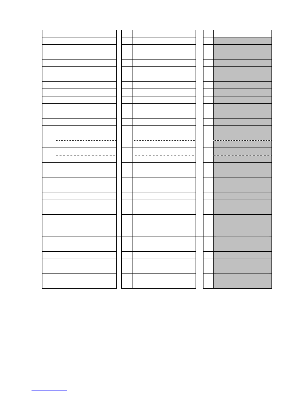
No Dutch No Spanish No Japanese
1 IN LIJN 1 PREPARADA 1
2 PRINTKOP OPEN. 2 CABEZAL ABIERTO 2
3 PAUZE 3 PAUSA 3
4 COMMUNICATIE FOUT 4 ERROR DE COMUNICACION 4
5 PAPIER STORING. 5 ATASCO DE PAPEL 5
6 FOUT SNIJMES 6 ERROR DE CORTADOR 6
7 GEEN PAPIER 7 SIN PAPEL 7
8 GEEN LINT 8 SIN CINTA 8
9 PRINTKOP OPEN. 9 CABEZAL ABIERTO 9
10 FOUT PRINTKOP 10 ERROR DE CABEZAL 10
11 PRINTKOP OVERHIT. 11 EXCESO TEMP. CABEZAL 11
12 LINT FOUT 12 ERROR DE CINTA 12
13 OPROLEENHEID VOL 13 REBOBINADOR LLENO 13
OPSLAAN ####KB/&&&&KB SALVAR ####KB/&&&&KB
14
OPSLAAN %%,%%%,%%%KB
14
SALVAR %%,%%%,%%%KB
14
FORMAT ####KB/&&&&KB FORMATO ####KB/&&&&KB
15
FORMAT %%,%%%,%%%KB
15
FORMATO %%,%%%,%%%KB
15
16 LADEN . . . 16 CARGANDO... 16
17 INSTELMODUS 17 MODO CONFIG. 17
18 MEM SCHRIJF FOUT 18 ERROR DE ESCRITURA 18
19 FORMAT FOUT 19 ERROR DE FORMATO 19
20 GEHEUGEN VOL 20 MEMORIA LLENA 20
21 SYNTAX FOUT 21 ERROR DE SINTAXIS 21
22 VOEDING FOUT 22 FALLO DE ALIMENTACION 22
23 FOUT EEPROM
23 ERROR EN LA EEPROM 23
24 SYSTEEM FOUT. 24 ERROR DE SISTEMA 24
25 INIT CLIENT DHCP 25 INIC. CLIENTE DHCP... 25
26 SCHRIJFFOUT RFID 26 ERROR ESCRITURA RFID 26
27 RFID FOUT 27 ERROR EN RFID 27
28 INPUT PASSWORD 28 INPUT PASSWORD 28
29 ONGELDIG PASWOORD 29 CONTRASEÑA NO VALIDA 29
30 RFID CONFIG. FOUT 30 ERROR DE CONFIG. RFID 30
31 LAGE BATTERIJ. 31 BATERIA BAJA 31
32 INTERNE COMM. FOUT 32 ERR INTERNO COMUNIC. 32
Page 29
24
No Italian No Portuguese
1 On Line 1 PREPARADA
2 Testina Aperta 2 CABECA ABERTA
3 PAUSA 3 PAUSA
4 Errore Seriale 4 ERRO DE COMUNICACAO
5 Carta inceppata 5 PAPEL ENCRAVADO
6 Errore Taglierina 6 ERRO DE CORTADOR
7 Manca Carta 7 SEM PAPEL
8 Manca Nastro 8 SEM FITA
9 Testina Aperta 9 CABECA ABERTA
10 ERRORE TESTINA 10 ERRO DE CABECA
11 Temp. testa alta 11 EXCESSO TEMP. CABECA
12 ERRORE NASTRO 12 ERRO DE FITA
13 REWINDER PIENO 13 REBOBINADOR CHEIO
SALVA ####KB/&&&&KB SALVAR ####KB/&&&&KB
14
SALVA %%,%%%,%%%KB
14
SALVAR %%,%%%,%%%KB
FORMAT ####KB/&&&&KB FORMATO ####KB/&&&&KB
15
FORMAT %%,%%%,%%%KB
15
FORMATO %%,%%%,%%%KB
16 CARICAMENT 16 A CARREGAR...
17 Configurazione 17 MODO CONFIG.
18 Err. Scritt. memoria 18 ERRO DE ESCRITA
19 ERRORE FORMATTAZIONE 19 ERRO DE FORMATO
20 Memoria piena 20 MEMORIA CHEIA
21 SYNTAX ERROR 21 ERRO DE SINTAXE
22 ERRORE ALIMENT. 22 FALHA DE ALIMENTACAO
23 Errore EEPROM 23 ERRO NA EEPROM
24 SYSTEM ERROR 24 ERRO DE SISTEMA
25 DHCP CLIENT INIT... 25 INIC. CLIENTE DHCP...
26 RFID WRITE ERROR 26 ERRO ESCRITA RFID
27 RFID ERROR 27 ERRO EM RFID
28 INPUT PASSWORD 28 INPUT PASSWORD
29 PASSWORD ERRATA 29 SENHA INVALIDA
30 RFID CONFIG ERR 30 ERRO DE CONFIG. RFID
31 BATTERIA BASSA 31 POUCA BATERIA
32 Errore Comm Interna
32 ERR INTERNO COMUNIC.
Page 30
25
7 DISPLAY PATTERN AND KEY OPERATION FOR SYSTEM MODE AND
USER MODE
7.1 LIST BOX WITH SCROLLBAR
The list box is used for displaying the menus or items to be selected. It is comprised of the following parts.
The knob appears on the scrollbar when the number of scroll lines is over 4 lines.
There are three types of list box with scrollbar, as follows.
Display
Menu display (without setting value)
Menu display (with setting value)
Setting value selection display
Key function (Menu display)
Key Compatible Key Function
[MODE] None Returns to the top menu without saving changes.
[CANCEL] [FEED] + [RESTART] Returns to the upper hierarchy without saving changes.
[ENTER] [PAUSE] Displays a next screen.
[UP] [RESTART] Moves the cursor upward. The cursor does not move any
further when the selected option is listed at the top.
[DOWN] [FEED] Moves the cursor downward. The cursor does not move any
further when the selected option is listed at the bottom.
[LEFT] None No function
[RIGHT] None No function
Knob
Scrollba
r
Title
Scroll line (up to 4 lines)
Page 31

26
Key function (value setting display)
Key Compatible Key Function
[MODE] None Returns to the top menu without saving changes.
[CANCEL] [FEED] + [RESTART] Returns to the upper hierarchy without saving changes.
[ENTER] [PAUSE] Saves the changes and returns to the upper hierarchy.
[UP] [RESTART] Moves the cursor upward. The cursor does not move any
further when the selected option is listed at the top.
[DOWN] [FEED] Moves the cursor downward. The cursor does not move any
further when the selected option is listed at the bottom.
[LEFT] None No function
[RIGHT] None No function
When multiple keys other than specified above ([FEED] + [RESTART]) are pressed at the same time, the printer
behavior is not guaranteed.
Page 32

27
Movement of the cursor when scrolled
The cursor moves in the following way with a depression of the [UP] or [DOWN] key. The following table shows
the example of depression of the [DOWN] key. The [UP] key functions in the same way.
Display Key operation
Press
[DOWN] key
The position of the displayed menus remains
unchanged and only the cursor moves to one line
below.
Press
[DOWN] key
The position of the displayed menus remains
unchanged and only the cursor moves to one line
below.
Press
[DOWN] key
The entire menu moves up by one line and the
cursor moves to the next item.
Press
[DOWN] key
The entire menu moves up by one line and the
cursor moves to the next item.
Press
[DOWN] key
The position of the displayed menus remains
unchanged and only the cursor moves to one line
below.
Page 33

28
The cursor position when shifting from upper menu to its sub menu
When shifting from upper menu to its sub menu, the cursor is positioned at the topmost item except for RFID
setting menu. (Because the RFID menu items show the setting value.)
The cursor position when shifting from upper menu to its subordinate value setting display
When shifting from upper menu to its subordinate value setting display, the cursor is positioned at the
currently selected item.
The cursor position when shifting from sub menu or value setting display to its upper menu
When shifting from lower menu or value setting display to its upper menu, the cursor is positioned at the
previously selected item.
When the [MODE] key is pressed while the main menu is displayed:
When the [MODE] key is pressed while the main menu of the system mode or user system mode, the cursor
is positioned at the topmost item.
When the [CANCEL] key is pressed while the main menu is displayed:
When the [CANCEL] key is pressed while the main menu of the system mode or user system mode, the
cursor does not move from the current position.
Page 34

29
7.2 VALUE SETTING DISPLAY
The value setting display is used for setting a value by increasing or decreasing it.
It is comprised of the following parts.
Display example
The currently programmable item is highlighted.
The display of the symbols like “+” and “-“, and the unit of measure like “mm” and “step” differs depending on the
item to be set.
Display
Setting display with one field
Setting display with multiple fields (placed
horizontally)
Setting display with multiple fields (placed
vertically)
Key function (Setting display with one field)
Key Compatible Key Function
[MODE] None
Returns to the top menu without saving changes.
[CANCEL] [FEED] + [RESTART]
Returns to the upper hierarchy without saving changes.
[ENTER] [PAUSE]
Saves the changes and returns to the upper hierarchy.
[UP] [RESTART]
Increases the setting value by specified step. When the setting
value reaches the maximum, it does not increase any further.
[DOWN] [FEED]
Decreases the setting value by specified step. When the
setting value reaches the minimum, it does not decrease any
further.
[LEFT] None No function
[RIGHT] None No function
Setting value
Setting range
Title
Page 35

30
Key operation (Setting display with multiple fields (horizontal))
Key Compatible Key Function
[MODE] None
Returns to the top menu without saving changes.
[CANCEL] [FEED] + [RESTART]
Returns to the upper hierarchy without saving changes.
[ENTER] [PAUSE]
Saves the changes and returns to the upper hierarchy.
[UP] [RESTART]
Increases the setting value by specified step. When the setting
value reaches the maximum, it does not increase any further.
[DOWN] [FEED]
Decreases the setting value by specified step. When the
setting value reaches the minimum, it does not decrease any
further.
[LEFT] None
Moves the cursor to the left field. The cursor does not move
any further when the left-most field is selected.
[RIGHT] None
Moves the cursor to the right field. The cursor does not move
any further when the right-most field is selected.
Key function (Setting display with multiple fields (vertical))
Key Compatible Key Function
[MODE] None
Returns to the top menu without saving changes.
[CANCEL] [FEED] + [RESTART]
Returns to the upper hierarchy without saving changes.
[ENTER] [PAUSE]
Saves the changes and returns to the upper hierarchy.
[UP] [RESTART]
Increases the setting value by specified step. When the setting
value reaches the maximum, it does not increase any further.
[DOWN] [FEED]
Decreases the setting value by specified step. When the
setting value reaches the minimum, it does not decrease any
further.
[LEFT] None
Moves the cursor to the upper field. The cursor does not
move any further when the topmost field is selected.
[RIGHT] None
Moves the cursor to the lower field. The cursor does not
move any further when the bottom field is selected.
Page 36

31
7.3 INFORMATION DISPLAY
The information display is used when no input or setting is performed.
It is consists of the following parts.
Display example
Display
Scroll
RFID tag read
Key function
Key Compatible Key Function
[MODE] None Displays the top menu.
[CANCEL] [FEED] + [RESTART] Displays the upper hierarchy.
[ENTER] [PAUSE] Displays the upper hierarchy.
[UP] [RESTART] No function
[DOWN] [FEED] No function
[LEFT] None No function
[RIGHT] None No function
Title
Information
Page 37

32
Key function (Scroll)
Key Compatible Key Function
[MODE] None Displays the top menu.
[CANCEL] [FEED] + [RESTART] Displays the upper menu.
[ENTER] [PAUSE] Displays the upper menu.
[UP] [RESTART] Moves the cursor upward. The cursor does not move any
further when it is positioned at the top.
[DOWN] [FEED] Moves the cursor downward. The cursor does not move any
further when it is positioned at the bottom.
[LEFT] None No function
[RIGHT] None No function
Key function (RFID tag read)
Key Compatible Key Function
[MODE] None Displays the top menu without saving changes.
[CANCEL] [FEED] + [RESTART] Displays the upper menu without saving changes.
[ENTER] [PAUSE] RFID tag is read again.
[UP] [RESTART] Displays the data of the previous tag. The display does not
change when the first tag data is being shown.
[DOWN] [FEED] Displays the data of the next tag. The display does not
change when the last tag data is being shown.
[LEFT] None No function
[RIGHT] None No function
Page 38

33
7.4 SENSOR ADJUSTMENT DISPLAY
The sensor adjustment display is used only when the level of the sensors provided on the printer is adjusted.
It is comprised of the following parts.
Display example
Display
Before adjustment
After adjustment
Key function (before adjustment)
Key Compatible Key Function
[MODE] None Displays the top menu.
[CANCEL] None Displays the upper hierarchy.
[ENTER] None When held down for 3 seconds or more, the sensor adjustment
is performed.
When this key is released within 3 seconds, the display returns
to the upper hierarchy display.
[UP] None No function
[DOWN] None No function
[LEFT] None No function
[RIGHT] None No function
Sensor level
Message
Title
Page 39

34
Key function (after adjustment)
Key Compatible Key Function
[MODE] None Displays the top menu.
[CANCEL] None Displays re-adjustment menu.
[ENTER] None Displays the upper menu.
[UP] None No function
[DOWN] None No function
[LEFT] None No function
[RIGHT] None No function
The asterisk “*” shown on the right side of the adjustment value indicates the completion of adjustment.
The voltage under adjustment is updated approximately every 200 msec.
Page 40

35
7.5 TEMPERATURE DISPLAY
Temperature display is used only for displaying the print head temperature and ambient temperature.
It is comprised of the following parts.
Display example
Display
Key function
Key Compatible Key Function
[MODE] None Displays the top menu.
[CANCEL] None Displays the upper hierarchy display.
[ENTER] None Displays the upper hierarchy display.
[UP] None No function
[DOWN] None No function
[LEFT] None No function
[RIGHT] None No function
Each temperature is updated approximately every 200 msec.
Title
Ambient temperature
Print head temperature
Page 41

36
7.6 File Selection Display
File selection display is used for selecting a file when copying data from USB memory to the printer.
It is comprised of the following parts.
Display example
The scrollbar on the file selection display is not provided with the knob regardless of the number of files.
There are two types of file selection displays, as follows.
Copy data selection display
CFG file selection display
Key function
Key Compatible Key Function
[MODE] None Displays the top menu without selecting a file.
[CANCEL] [FEED]+[RESTART] Displays the previous display without selecting a file.
[ENTER] [PAUSE] Displays the next display.
[UP] [RESTART] Moves the cursor upward. The cursor does not move any
further when it is positioned at the top.
[DOWN] [FEED] Moves the cursor downward. The cursor does not move any
further when it is positioned at the bottom.
[LEFT] None No function
[RIGHT] None No function
Printer operation is not guaranteed when multiple keys are pressed except for those mentioned above
([FEED]+[RESTART]).
Title
Scroll lines (4 lines)
Scroll ba
r
Page 42
37
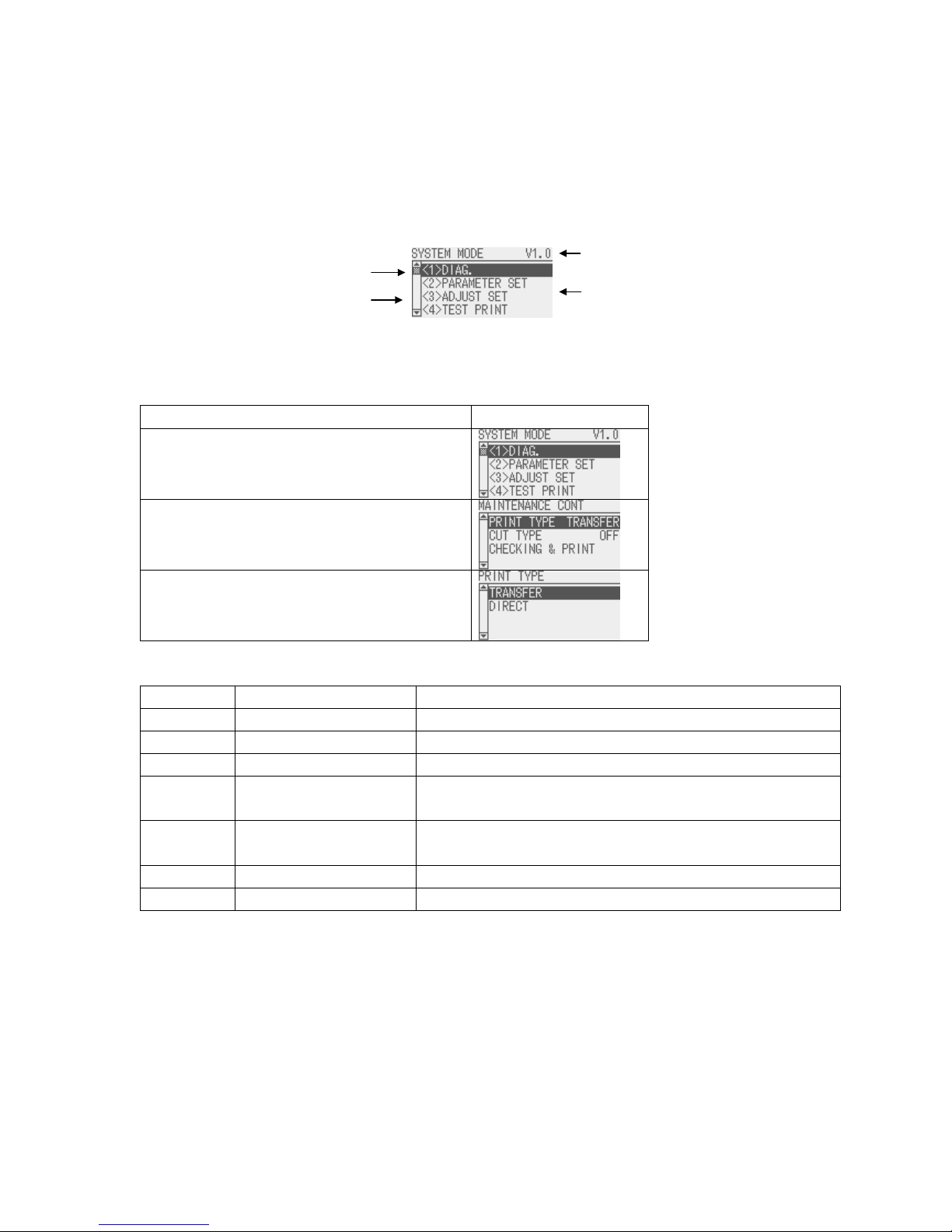
8 SYSTEM MODE
8.1 OUTLINE OF SYSTEM MODE
The printer enters the system mode when the following operation is performed when the printer power is off.
・ Turn on the printer while holding down the [FEED] and [PAUSE] keys at the same time.
・ Turn on the printer while holding down the [MODE] key.
The system mode is intended for performing self-test, parameter setting, and other settings.
When the top menu is displayed, the firmware version is shown on the right side of the title.
The language displayed on the panel is Japanese when Japanese is selected for the LCD language parameter,
and English when English, German, French, Dutch, Spanish, Italian or Portuguese is selected.
The key operations for the system mode are described below.
Key operations follow Section 7.1 LIST BOX WITH SCROLLBAR.
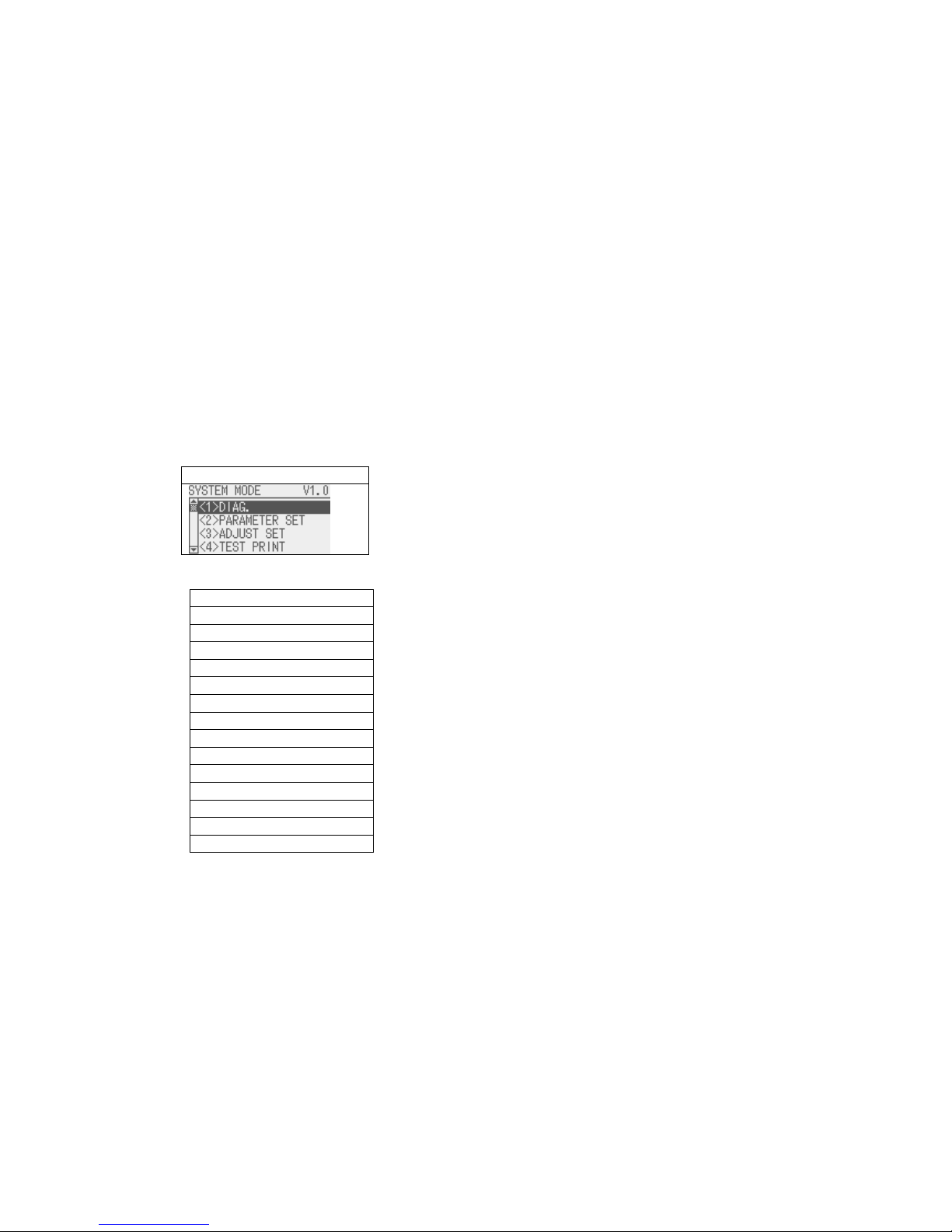
Display
Top menu for QM/CN model
English
<1>DIAG.
<2>PARAMETER SET
<3>ADJUST SET
<4>TEST PRINT
<5>SENSOR ADJUST
<6>RAM CLEAR
<7>INTERFACE
<8>BASIC
<9>FOR FACTORY
<10>RFID
<11>RTC
<12>Z-MODE
<13>USB MEMORY
<14>RESET
Page 43

38
DIAG. Used to perform self diagnosis, print out the result, check for the print head
broken elements.
PARAMETER SET Used to set the parameters for each printer function.
ADJUST SET Used to fine adjust the printer mechanism position and sensor.
TEST PRINT Used to conduct test print by printing slant lines, characters and barcodes.
SENSOR ADJUST Used to display the ambient temaprature and print head temparature, and adjust
each level of the media sensor.
RAM CLEAR Used to clear the maintenance counter and parameters.
INTERFACE Used to set the parameters of the interface such as network, USB, RS232C and
parallel.
BASIC Used to set the function of the BASIC program when it is loaded printer.
FOR FACTORY Used to adjust the printer before shipment.
RFID Used to set RFID-related parameters.
RTC Used to set the date & time of the real time clock, enable or disable the low
battery check, and choose a real time renewal timing.
Z-MODE Same as BASIC.
USB MEMORY Used to copy data to/from USB memory.
RESET Used to reset the printer.
8.2 REFLECTING THE SYSTEM MODE SETTINGS IN THE PRINTER
The settings configured in the system mode or user system mode are saved in the printer at the following timing,
depending on the items to be saved.
・ Periodic save at 20-msec. interval
・ When Reset menu in the system mode or user system mode is performed
The changes in the settings, with a partial exception, take effect at a power on time or after a reset.
Page 44

39
8.3 DIAG
The main firmware version is displayed on the right side of the title.
Contents of DIAG. menu
MENU ITEM Display pattern and key operation
SYSTEM MODE
<1>DIAG.
MAINTENANCE CONT
AUTO DIAGNOSTIC
7.1 LIST BOX WITH SCROLLBAR
HEAD CHECK 7.3 INFORMATION DISPLAY
8.3.1 MAINTENANCE CONT
This section describes how to print out the maintenance counter data.
The following table shows the menu structure from the top menu of the system mode to MAINTENAN
CE CONT.
MENU ITEM Display pattern and key operation
SYSTEM MODE
<1>DIAG.
MAINTENANCE CONT
PRINT TYPE
TRANSFER
DIRECT
CUT TYPE
OFF
ON
7.1 LIST BOX WITH SCROLLBAR
CHECKING & PRINT 7.3 INFORMATION DISPLAY
When an error occurs while printing, the error message is displayed, the ERROR LED turns on, and the
ONLINE LED turns off. Though the error can be cleared by presing [ENTER], [CANCEL] or [MODE] key, the
printer does not print the erroneous label.
Page 45
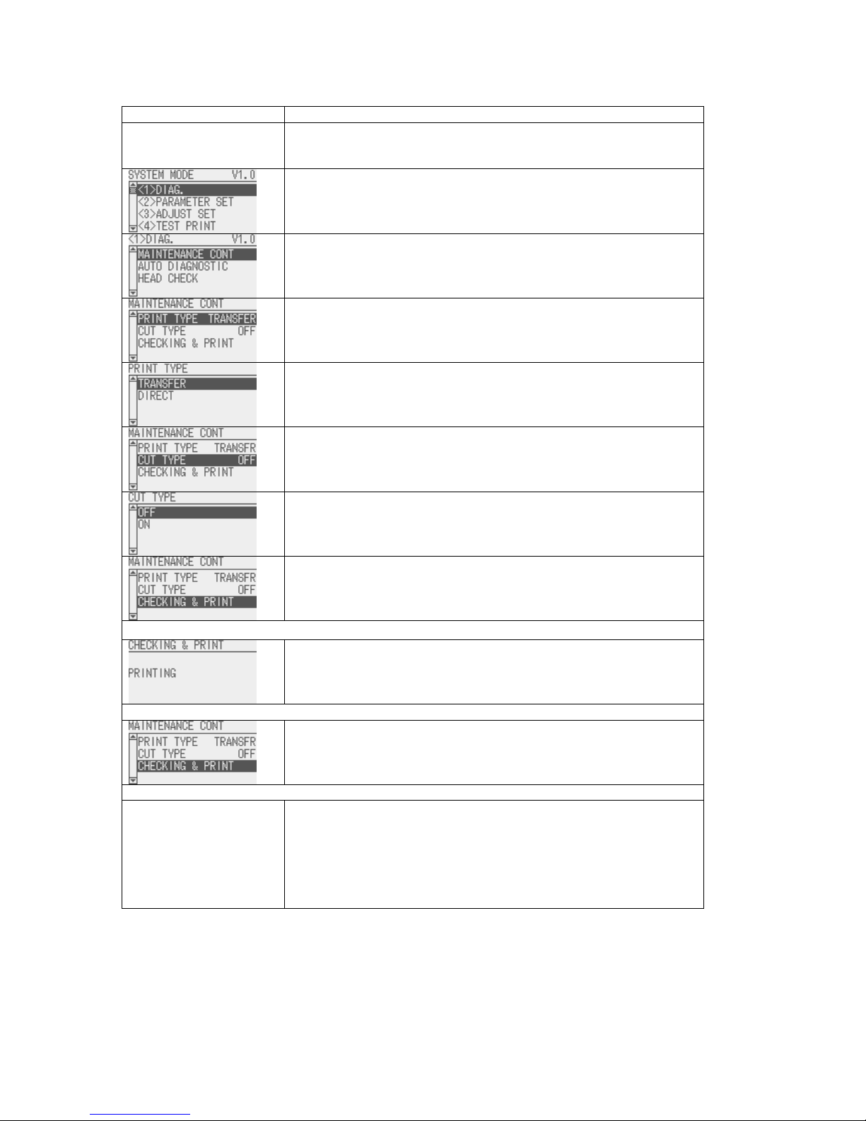
40
Menu operation example
Display Procedure
Turn on the printer while holding down [FEED] and [RESTART] keys
at the same time.
SYSTEM MODE menus are displayed.
Select <1>DIAG. and press [ENTER] key.
Submenus of <1>DIAG. are displayed.
Select MAINTENANCE CONT and press [ENTER] key.
Submenus of MAINTENANCE CONT are displayed.
Select PRINT TYPE and press [ENTER] key.
PRINT TYPE menu is displayed.
Select either print method.
When [ENTER] key is pressed, the display returns to
MAINTENANCE CONT menu.
Press [DOWN] key, select CUT TYPE, and press [ENTER] key.
CUT TYPE menu is displayed.
Select OFF or ON for CUT TYPE.
When [ENTER] key is pressed, the display returns to
MAINTENANCE CONT menu.
Press [DOWN] key, select CHECKING & PRINT, and press
[ENTER] key.
The maintenance counter and self-diagnosis result are printed.
While printing …
“PRINTING” is displayed.
When the printing normally ends:
The display returns to MAINTENANCE CONT menu.
When a print error occurs:
The printer stops printing displaying the error message.
The ERROR LED turns on and the ONLINE LED turns off.
The display returns to MAINTENANCE CONT menu when [ENTER]
or [CANCEL] key is pressed. At this time, the ERROR LED turns
off and the ONLINE LED turns on.
Note that the printer does not automatically re-print the erroneous
label after recovery from the error.
Page 46

41
8.3.1.1 COUNTER PARAMETER PRINT CONTENTS
<< COUNTER >>
TOTAL FEED 0.0km [QM]
FEED 0.0km
FEED1 0.0km
FEED2 0.0km
FEED3 0.0km
FEED4 0.0km
PRINT 0.0km
PRINT1 0.0km
PRINT2 0.0km
PRINT3 0.0km
PRINT4 0.0km
CUT 0
HEAD U/D 0
RIBBON 0h
SOLENOID 0h
232C ERR 0
SYSTEM ERR 0
POWER FAIL 0
<< ADJUST >>
[PC] [KEY]
FEED +0.0mm FEED +0.0mm
CUT +0.0mm CUT +0.0mm
BACK +0.0mm BACK +0.0mm
TONE(T) +0step TONE(T) +0step
TONE(D) +0step TONE(D) +0step
RBN(FW) +0 RBN(FW) +0
RBN(BK) +0 RBN(BK) +0
X ADJ. +0.0mm
THRESHOLD(R) 0.0V
THRESHOLD(T) 0.0V
<< PARAMETER SETTINGS >>
MEDIA LOAD [STD]
FORWARD WAIT [ON] +0.0mm [MODE1]
HU CUT/RWD. [OFF]
RIBBON SAVE [ON:TAG]
PRE PEEL OFF [OFF]
BACK SPEED [STD]
A
UTO CALIB [OFF]
FONT [PC-850] [0]
CODE [AUTO]
PEEL OFF STATUS [ON]
USB I/F STATUS [OFF]
FEED KEY [FEED]
KANJI [TYPE1]
EURO CODE [B0]
A
UTO HD CHK [OFF]
WEB PRINTER [OFF]
RIBBON NEAR END [OFF]
EX.I/O MODE [TYPE1]
LBL/RBN END [TYPE1]
MAXI CODE SPEC. [TYPE1]
XML [STD]
THRESHOLD SEL(R) [MANUAL SET]
THRESHOLD SEL(T) [MANUAL SET]
ENERGY TYPE(T) [Semi resin1]
ENERGY TYPE(D) [Standard]
POWER SAVE TIME [ 15min]
BASIC [OFF]
BASIC TRACE [OFF]
<< PANEL >>
MESSAGE [ENGLISH]
MACHINE NAME [ON]
PRINT PAGE [ON]
IP ADDRESS [ON]
CONTRAST [40]
SYSTEM PASSWORD [OFF]
<< STORAGE AREA >>
TTF AREA [ 0KB]
EXT CHR AREA [ 0KB]
BASIC AREA [ 0KB]
PC SAVE AREA [ 0KB]
<< USB >>
SERIAL NUMBER [DISABLE]
[XXXXXXXXXXXX]
<< RS-232C >>
SPEED [9600]
DATA LENGTH [8]
STOP BIT [1]
PARITY [EVEN]
CONTROL [XON+READY AUTO]
<< CENTRO >>
A
CK/BUSY [TYPE1]
INPUT PRIME [ON]
PLUG & PLAY [OFF]
<< LAN/WLAN >>
LAN/WLAN [OFF]
SNMP [OFF]
PRTR IP ADDRESS [192.168.010.020]
GATE IP ADDRESS [000.000.000.000]
SUBNET MASK [255.255.255.000]
SOCKET PORT [OFF] [08000]
DHCP [OFF]
DHCP CLIENT ID [FFFFFFFFFFFFFFFFFFFF]
[FFFFFFFFFFFFFFFFFFFF]
[FFFFFFFFFFFFFFFFFFFF]
[FFFFFFFFFFFFFFFFFFFF]
[FFFFFFFFFFFFFFFFFFFF]
[FFFFFFFFFFFFFFFFFFFF]
[FFFFFFFF]
DHCP HOST NAME [ABCDEFGHIJKLMNOPQRST]
[UVWXYZ123456]
WLAN STANDARD [11b/g]
WLAN MODE [INFRASTRUCTURE]
ESS ID [ ]
[ ]
ENCRYPT [OFF]
WPA MODE [OFF]
A
UTH [OPEN SYSTEM]
DEFAULT KEY [1]
802.1X SUPPLICANT [OFF]
802.11b CHANNEL [01]
802.11b BAUD RATE [11M]
802.11g CHANNEL [01]
802.11g BAUD RATE [54M]
WINS [OFF]
WINS IP ADDRESS [000.000.000.000]
LPR [OFF]
<< RFID >>
MODULE [NONE]
TAG TYPE [NONE ]
RF CHANNEL [AUTO]
A
DJUST RETRY [+00mm]
ISSUE RETRY [ 3labels]
READ RETRY [ 5times] [4.0sec]
WRITE RETRY [ 5times] [4.0sec]
POWER LEVEL [ 0]
Q VALUE [ 0]
A
GC THRESHOLD [ 0]
WRITE AGC [ 0]
RETRY MIN AGC [ 0]
TAG CHECK [PASSWORD] [ON] [ON]
MULTI WRITE [OFF]
WRITE OK TAGS 9999999
VOID PRINT TAGS 9999999
<< RTC >>
BATTERY CHECK [ON]
RENEWAL [BATCH]
Page 47

42
Print condition:
Label length 490 mm
Print method User setting
Sensor type None
203 dpi 6 ips
300 dpi/305 dpi 5 ips
Speed
600 dpi 3 ips
Print count 1
Issue mode User setting
Other No rewinder motor activated
<< COUNTER >>
Item Content Range
Counting condition
TOTAL FEED Total label distance covered (cannot be
cleared)
0.0 to 3200.0 km
Counted when the paper feed motor are driven to feed a paper or print. (Reverse feed is also counted.)
When the power is turned off, the label distance of 50.0 cm or less may be rounded down when backed up.
FEED Label distance covered 0.0 to 3200.0 km
Counted when the paper feed motor are driven to feed a paper or print. (Reverse feed is also counted.)
When the power is off, the label distance of 50.0 cm or less may be rounded down when backed up.
FEED1 to FEED4 History of label distances covered 0.0 to 3200.0 km
History of the last 4 label distances.
PRINT Print distance 0.0 to 200.0 km
Counted while printing. (Reverse feed is not counted.)
B-EX4T1-G:
When the power is turned off, the print distance of 8.2 m or less is rounded down and backed up.
B-EX4T1-T:
When the power is turned off, the print distance of 5.5 m or less is rounded down when backed up.
PRINT1 to PRINT4 History of print distances 0.0 to 3200.0 km
History of the last 4 print distances.
CUT Cut count 0 to 1000000
Every cut operation is counted.
When the power is turned off, a cut count of 31 or less is rounded down when backed up.
HEAD U/D Head up/down count 0 to 2000000
The number of times the print head moves up and down with the solenoid for ribbon save is counted. (A
set of up and down is counted as one.)
When the power is turned off, head up/down count of 31 or less is rounded down when backed up.
RIBBON Ribbon motor drive time 0 to 2000 hours
Counted when the ribbon motor is driven while paper feed or printing. (Reverse feed is also counted.)
For B-EX4T1-G:
When the power is turned off, drive time of 32 seconds or less is rounded down when backed up.
For B-EX4T1-T:
When the power is turned off, drive time of 27 seconds or less is rounded down when backed up.
SOLENOID Head-up solenoid drive time 0 to 1000 hours
Counted when the ribbon saving operation is performed.
When the power is turned off, drive time of 32 seconds or less is rounded down when backed up.
232C ERR RS-232C hardware error count 0 to 255
Counted when a parity error, overrun error or framing error occurs.
SYSTEM ERR System error count 0 to 15
Counted when a system error occurs.
POWER FAIL Momentary power interruption count 0 to 15
Counted when a momentary power interruption occurs.
Page 48

43
<< ADJUST >>
Item Description Remarks
[PC] FEED Feed amount fine adjustment -50.0mm to +50.0mm (*1)
CUT
Cut position (or strip position) fine
adjustment
-50.0mm to +50.0mm (*1)
BACK
Back feed fine adjustment
-9.9mm to +9.9mm (*1)
TONE (T)
Print density fine adjustment
(Thermal transfer print mode)
-10 to +10 step
TONE (D)
Print density fine adjustment
(Direct thermal print mode)
-10 to +10 step
RBN (FW)
Ribbon motor drive voltage fine
adjustment (Take-up)
-15 to +10 step
RBN (BK)
Ribbon motor drive voltage fine
adjustment (Back tension)
-15 to +10 step
[KEY] FEED
Feed amount fine adjustment
-50.0mm to +50.0mm
CUT
Cut position (or strip position) fine
adjustment
-50.0mm to +50.0mm
BACK
Back feed fine adjustment
-9.9mm to +9.9mm
TONE (T)
Print density fine adjustment
(Thermal transfer print mode)
-20 to +10 step
TONE (D)
Print density fine adjustment
(Direct thermal print mode)
-20 to +10 step
RBN (FW)
Ribbon motor drive voltage fine
adjustment (Take-up)
-15 to +10 step
RBN (BK)
Ribbon motor drive voltage fine
adjustment (Back tension)
-15 to +10 step
X ADJ.
X-coordinate fine adjustment
-99.5mm to +99.5mm
THRESHOLD<R>
Threshold fine adjustment for
reflective sensor
0.0V to 4.0V
THRESHOLD<T>
Threshold fine adjustment for
transmissive sensor
0.0V to 4.0V
(*1) For B-EX4T1-G, the print head density is 8 dots/m. The printer behavior is the same regardless of whether
the value is set to “x.2 mm” or “x.3 mm.” Therefore, “x.3mm” is printed on the maintenance counter printout
even if “x.2 mm” is set. Similarly, when “x.7 mm” is set, “x.8 mm” is printed on the maintenance counter printout.
Page 49

44
<< PARAMETER SETTINGS >>
Item Description Printed value
OFF Disabled
STD Feeds the detected
gap/mark to print start
position.
ECO Feeds gap/mark between
print head and sensor to
print start position.
MEDIA LOAD Media loading
ECO+BFeed Back feed follows ECO
printer behavior.
ON Performed
(A fine adjustment value
for the stop position is
also printed.)
FORWARD WAIT Forward feed standby after
issue
OFF Not performed
MODE1 Stops after 13.7-mm
forward feed.
FW/BK ACT. Forward feed standby action
MODE2 Stops after 6-mm back
feed and 3-mm forward
feed. (Only when the cut
mode, thermal transfer,
and feed gap sensor is
selected.) In other cases,
the printer stops after
13.7-mm forward feed.
ON
Head-up operation is
performed, or the
rewinder is used.
HU CUT/RWD. Head-up operation in cut
issue mode, or use of the
rewinder
OFF Head-up operation is not
performed, or the
rewinder is not used.
ON: TAG Used.
Head lever position:
“TAG”
ON: LBL Used.
Head lever position:
“LABEL”.
RBN SAVE Use of ribbon saving module
OFF Not used
ON Pre-peel-off is performed.PRE PEEL OFF Pre-peel-off process setting
OFF Pre-peel-off is not
performed.
STD 3 ips BACK SPEED Back feed speed setting
LOW 2 ips
OFF Auto calibration is not
performed.
ON TRANS. Auto calibration is
performed with
transmissive sensor.
ON REFLECT Auto calibration is
performed with reflective
sensor.
ON ALL Auto calibration is
performed with both
sensors.
AUTO CALIB Auto calibration setting
ON
TRANS+Bfeed
Back feed follows ON
TRANS printer behavior.
Page 50

45
ON
REFLECT+Bfeed
Back feed follows ON
REFLECT printer
behavior
ON ALL+Bfeed Back feed follows ON ALL
printer behavior.
PC-850 PC-850
PC-852 PC-852
PC-857 PC-857
PC-8 PC-8
PC-851 PC-851
PC-855 PC-855
PC-1250 PC-1250
PC-1251 PC-1251
PC-1252 PC-1252
PC-1253 PC-1253
PC-1254 PC-1254
PC-1257 PC-1257
LATIN9 LATIN9
PC-866 PC-866
Arabic Arabic
Character code selection
UTF-8 UTF-8
0
No slash used
FONT
Font “0” selection
Ø Slash used
AUTO Automatic selection
ESC LF NUL ESC LF NUL method
{ | } { | } method
CODE Control code type
×× ○○ Any code (Described in
hex. code)
ON Selected PEEL OFF STATUS Peel-off wait status selection
OFF Not selected
ON Sends USB I/F STATUS USB interface status
OFF Not send
FEED One label is fed. FEED KEY [FEED] key function setting
PRINT Data in the image buffer is
printed on one label.
TYPE1 For WINDOWS codes KANJI Kanji code type
TYPE2 For original codes
EURO CODE Euro code setting
ON Automatic broken dots
check is performed.
AUTO HD CHK Automatic broken dots check
setting
OFF Automatic broken dots
check is not performed.
ON INTERNAL Enabled. (Internal
memory is used.)
ON EXTERNAL Enabled. (External
memory is used.)
WEB PRINTER Web printer function setting
OFF Disabled.
30m Ribbon near end state is
detected when the
remaining ribbon length is
approximately 30 m.
70m Ribbon near end state is
detected when the
remaining ribbon length is
approximately 70 m.
RIBBON NEAR END Ribbon near end detection
setting
OFF Ribbon near end state is
not detected.
EX.I/O MODE Expansion I/O operation TYPE1 Standard mode.
Page 51

46
mode TYPE2 In-line mode.
TYPE1 When a label end or
ribbon end state is
detected, the printer stops
immediately.
LBL/RBN END Label end/ribbon end process
setting
TYPE2 When a label end or
ribbon end state is
detected, the printer prints
the current label as far as
possible, and then stops.
TYPE1 Compatible with the
current version
MAXI CODE SPEC. MaxiCode specification
setting
TYPE2 Special specification
OFF Disabled.
STD Standard specification.
ORACLE Specification for Oracle
SAP Specification for SAP
STD
EXTERNAL
Standard specification
(External memory is used)
ORACLE
EXTERNAL
Specification for Oracle
(External memory is used)
XML XML function setting
SAP
EXTERNAL
Specification for SAP
(External memory is used)
MANUAL SET Manually set value is
used.
THRESHOLD SEL(R) Threshold value for reflective
sensor
COMMAND
SET
Command specified value
is used.
MANUAL SET Manually set value is
used.
THRESHOLD SEL (T) Threshold value for
transmissive sensor
COMMAND
SET
Command specified value
is used.
Semi resin1 Semi resin 1
Semi resin2 Semi resin 2
Resin1 Resin 1
Resin2 Resin 2
Reserve1 Reserved.
Reserve2 Reserved.
Reserve3 Reserved.
Reserve4 Reserved.
Reserve5 Reserved.
ENERGY TYPE(T) Energy control for thermal
transfer print
Reserve6 Reserved.
Standard Standard
Reserve1 Reserved.
Reserve2 Reserved.
Reserve3 Reserved.
Reserve4 Reserved.
Reserve5 Reserved.
Reserve6 Reserved.
Reserve7 Reserved.
Reserve8 Reserved.
ENERGY TYPE(D) Energy control for direct
thermal print
Reserve9 Reserved.
POWER SAVE TIME Length of time until the printer
enters sleep mode
ON Basic interpreter is
enabled.
BASIC Basic interpreter setting
OFF Basic interpreter is
disabled.
ON Trace is enabled. BASIC TRACE Basic interpreter trace setting
OFF Trace is disabled.
Page 52

47
<< PANEL >>
Item Description Printed value
ENGLISH English
GERMAN German
FRENCH French
DUTCH Dutch
SPANISH Spanish
JAPANESE Japanese
ITALIAN Italian
MESSAGE Language selection for LCD
messages
PORTUGUESE Portuguese
ON Displayed. MACHINE NAME Whether to display the model name
OFF Hidden.
ON Displayed. PRINT PAGE Whether to display the number of
labels printed
OFF Hidden.
ON Displayed. IP ADDRESS Whether to display IP address
OFF Hidden.
CONTRAST LCD contrast
ON Password is
enabled.
SYSTEM PASSWORD Password for system mode
OFF Password is
disabled.
<< STORAGE AREA >>
Item Description Printed value
TTF AREA TrueType Font storage area size 0KB to 3072KB
(in 128KB units)
EXT CHR AREA Writable character storage area size 0KB to 3072KB
(in 128KB units)
BASIC AREA Basic file storage area size 0KB to 3072KB
(in 128KB units)
PC SAVE AREA PC command storage area size 0KB to 3072KB
(in 128KB units)
<< USB >>
Item Description Printed value
ENABLE Enabled. USB serial number
DISABLE Disabled.
SERIAL NUMBER
USB serial number
<< RS-232C >>
Item Description Printed value
2400 2400 bps
4800 4800 bps
9600 9600 bps
19200 19200 bps
38400 38400 bps
SPEED Baud rate
115200 115200 bps
7 7 bits DATA LENG. Data length
8 8 bits
1 1 bit STOP BIT Stop bit length
2 2 bits
NONE None
ODD Odd
PARITY Parity
EVEN Even
Page 53

48
XON/XOFF
XON/XOFF protocol
(No XON output when the power is
on, no XOFF output when the power
is off)
READY/BUSY
READY/BUSY (DTR) protocol
(No XON output when the power
is on, no XOFF output when the
power is off)
XON+READY
AUTO
XON/XOFF + READY/BUSY
(DTR) protocol
(XON output when the power is
on, XOFF output when the power
is off)
XON/XOFF
AUTO
XON/XOFF protocol
(XON output when the power is on,
XOFF output when the power is off)
CONTROL Transmission control
method
READY/BUSY
RTS
RTS protocol
(No XON output when the power is
on, no XOFF output when the power
is off)
<< CENTRO >>
Item Description Printed value
TYPE1 The ACK signal is sent to
match the rising edge of ACK
signal and the falling edge of
the BUSY signal.
ACK/BUSY Centronics ACK/BUSY timing
TYPE2 The ACK signal is sent to
match the falling edge of ACK
signal and the falling edge of
the BUSY signal.
ON Reset is performed. INPUT PRIME Reset process when the nInit
signal is ON
OFF Reset is not performed.
ON Plug-and-play is enabled. PLUG & PLAY Plug-and-play operation
OFF Plug-and-play is disabled.
<< LAN/WLAN >>
Item Description Printed value
OFF Disabled
AUTO Auto
LAN Wired LAN
LAN/WLAN LAN selection
WLAN Wireless LAN
ON Enabled SNMP SNMP enabled/disable
OFF Disabled
PRTR IP ADDRESS Printer IP address ***.***.***.***
GATE IP ADDRESS Gateway IP address ***.***.***.***
SUBNET MASK Subnet mask ***.***.***.***
ON Enabled Socket communication
OFF Disabled
SOCKET PORT
Socket communication port
number
0 to 65535
ON Enabled DHCP DHCP setting
OFF Disabled
DHCP CLIENT ID DHCP client ID setting (Hex.) Max. 64 characters
DHCP HOST NAME DHCP host name (ASCII) Max. 32 characters
11b/g 11b/g WLAN STANDARD Wireless LAN: Standard
11b 11b
Page 54

49
11g 11g
INFRASTRUCTURE Infrastructure
mode
WLAN MODE Wireless LAN: Connection
setting
ADHOC Adhoc mode
ESS ID Wireless LAN: ESS ID Max. 32 characters
OFF OFF
WEP40 WEP40
WEP104 WEP104
AES AES
ENCRYPT Wireless LAN: Encryption key
setting
TKIP TKIP
OFF OFF
WPA WPA
WPA-PSK WPA-PSK
WPA2 WPA2
WPA MODE Wireless LAN: WPA setting
WPA2-PSK WPA2-PSK
OPEN Open system
method
SHARED Shared key
method
AUTH Wireless LAN: Authentication
method
NETWORK EAP NETWORK EAP
DEFAULT KEY Wireless LAN: Encryption key
for sending
1 to 4
OFF OFF
EAP-TLS EAP-TLS
PEAP PEAP
EAP-TTLS EAP-TTLS
EAP-FAST EAP-FAST
EAP-MD5 EAP-MD5
802.1X SUPPLICANT Wireless LAN: Authentication
method
LEAP LEAP
802.11b CHANNEL Wireless LAN: 11b connection
channel setting
01 to 14
11M 11M
5.5M 5.5M
2M 2M
802.11b BAUD RATE Wireless LAN: 11b speed
setting
1M 1M
802.11g CHANNEL Wireless LAN: 11g connection
channel setting
01 to 13
54M 54M
48M 48M
36M 36M
24M 24M
18M 18M
12M 12M
9M 9M
6M 6M
11M 11M
5.5M 5.5M
2M 2M
802.11g BAUD RATE Wireless LAN: 11g speed
setting
1M 1M
ON Enabled WINS WINS enable/disable
OFF Disabled
WINS IP ADDRESS WINS IP address ***.***.***.***
ON Enabled LPR LPR enable/disable
OFF Disabled
Page 55

50
<< RFID >>
Item Description Printed value
NONE No RFID kit is installed.
H1 B-EX700-RFID-H1-QM-
R
H2 B-EX700-RFID-H2-R
MODULE RFID module type selection
U2 B-EX700-RFID-U2-(US/
EU/CN)-R
NONE
I-Code 11
Tag-it 12
C220 13
ISO15693 14
C210 15
C240 16
C320 17
TAG TYPE RFID tag type selection
EPC C1 Gen2 24
2CH to 8CH RF CHANNEL RFID channel setting
AUTO
ADJUST RETRY RFID adjustment for retry -99mm to
+99mm
ISSUE RETRY Max number of RFID issue
retries
0 to 255
Max number of RFID read
retries
0 to 255
READ RETRY
RFID read retry time-out 0 to 9.9 sec.
Max number of RFID write
retries
0 to 255
WRITE RETRY
RFID write retry time-out 0 to 9.9 sec.
POWER LEVEL RFID wireless power level
setting
B-EX700-RFIDU2-US/EU/CN-R
: 9 to 18
Q VALUE RFID module Q value 0 to 5
AGC THRESHOLD RFID AGC threshold setting 0 to15
WRITE AGC AGC threshold for data write 0 to15
RETRY MIN AGC AGC threshold lower limit for
retry
0 to15
OFF Detection is disabled.
ON (ID) RFID error tag detection
for ID area data
TAG CHECK RFID error tag detection
ON (ACCESS
PASSWORD)
When PASS is
selected, the following
settings are
subsequently
displayed:
Password setting to
protect error tag
detection
ON: Enabled
OFF: Disabled
Automatic unlock
function setting
ON: Enabled
OFF: Disabled
ON Enabled MULTI WRITE Hibiki tag multi-word write
OFF Disabled
Page 56
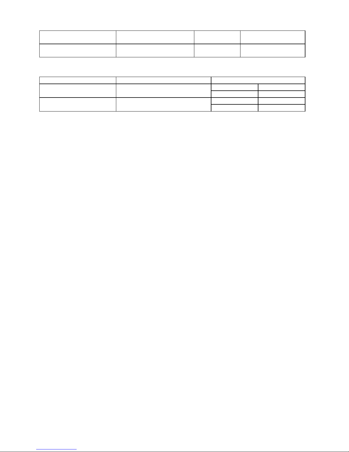
51
WRITE OK TAGS Count of RFID success label
write issue
0 to 9999999
VOID PRINT TAGS Count of RFID failure label
write issue
0 to 9999999
<< RTC >>
Item Description Printed value
ON Enabled BATTERY CHECK Battery check
OFF Disabled
BATCH per batch RENEWAL Time update timing
PAGE per page
Page 57

52
8.3.2 AUTO DIAGNOSTIC
The procedure for printing the self-diagnosis result is the same as that for the maintenance counter data. 8.3.1
MAINTENANCE CONT.
The following table shows the menu structure from top menu of the system mode to AUTO DIAGNOSTIC.
MENU ITEM Display pattern and key operation
SYSTEM MODE
<1>DIAG.
AUTO DIAGNOSTIC
PRINT TYPE
TRANSFER
DIRECT
CUT TYPE
OFF
ON
7.1 LIST BOX WITH
SCROLLBAR
CHECKING & PRINT 7.3 INFORMATION DISPLAY
When an error occurs while printing, the error message is displayed, the ERROR LED turns on, and the
ONLINE LED turns off. Though the error can be cleared by presing [ENTER], [CANCEL] or [MODE] key, the
printer does not print the erroneous label.
Page 58

53
8.3.2.1 AUTO SELF-DIAGNOSIS PRINTOUT
Print condition:
Label length 120 mm
Print method Setting by user
Sensor type None
203 dpi 6 ips Speed
300 dpi/305 dpi 5 ips
600 dpi 3 ips
Issuing number 1
Issuing mode User setting
Other No Rewinder motor activated.
(*1) “°” (degree) of “xx°C” may not be printed correctly, depend on the type of code page.
(*3) The Basic program file name and system mode program file name are printed.
When the first 4 characters of each program file name are “Z-EX”, the checksum will be also printed.
PROGRAM B-EX4T1-T
MAIN XXXXXXXXX V1.0A:1A00
BOOT XXXXXXXXX V1.0 :8500
WMON XXXXXXXXX V1.0 :6100
FONT 5600
KANJI NONE :0000
NONE :0000
EEPROM 256B
SDRAM 32MB
SENSOR1 00000000,00000111
SENSOR2 [H]23゚C [A]22゚C
[R]4.2V [T]2.5V [E]0.6V
PE LV. [R]1.8V [T]2.5V
M THRE. [R]1.8V [T]2.5V
HEAD [RANK]7 305DPI
LAN MAC 11-22-33-44-55-66
EXP.I/O NG
EX.232C NG
RFID OK #00RV972 (EU0) R01
WLAN OK Ver1.1.3
MAC 00-11-22-33-44-55
RTC NG
USB MEMORY NG
BASIC M Z-SX4-MV10F. V1.0F:7479
BASIC S Z-SX4-SV10E. V1.0E:AD36
Page 59

54
PROGRAM
B-EX4T1-G
Model name B-EX
MAIN
15OCT2002 V1.0A:1A00 Checksum
Version
Creation date (Day-Month-Year)
Name PROGRAM: Program area
BOOT
20SEP2002 V1.0:8500 Checksum
Version
Creation date (Day-Month-Year)
Name BOOT: Boot area
WMON
25OCT2010 V1.0:6100 Checksum
Version
Creation date (Day-Month-Year)
Name WMON: (WLAN) HTML area
FONT 5600
Checksum of font area
KANJI NONE
:0000 Checksum of bit map Kanji ROM for Gothic font
NONE: No Kanji ROM installed
GOTHIC: Bit map Kanji ROM for Gothic font installed
NONE
:0000 Checksum of bit map Kanji ROM for Mincho font
(or Chinese Kanji)
NONE: No Kanji ROM installed
MINCHO: Bit map Kanji ROM for Mincho font installed
CHINESE: Bit map Kanji ROM for
Chinese Kanji installed
EEPROM
256B 256B: The data of checking area can be read/write
correctly.
Alphanumeric character is capacity of EEPROM.
NG: The data of checking area cannot be read/write correctly.
Memory for backup
SDRAM
32MB Capacity of SDRAM
Memory for system and drawing
Page 60

55
Sensor check details
The value of non-installed sensor is unfixed.
SENSOR1 0 0 0 0 0 0 0 0
, 0 0 0 0 0 0 0 0
Thermal head open sensor
1: The head is closed.
(When the print head is unlocked, no printing
performed.)
Thermal head-up sensor
1: The head is lowered.
(When the print head is lifted, no printing performed.)
Cutter home position sensor
0: Home position
1: Outside the home position
Rewinder overflow sensor
0: Normal
1: Overflow
Ribbon take-up motor sensor
0: Outside the slit
1: Inside the slit
Ribbon feed motor sensor
0: Outside the slit
1: Inside the slit
Blank (Fixed to 0)
Strip sensor (Peel-off sensor)
0: Label is not present.
1: Label is present.
Blank (Fixed to 0)
Page 61

56
SENSOR2 [H]20゚C [A]22゚C
Ambient temperature sensor status
(0 to 86 °C, --°C if it cannot be detected)
Thermal head temperature sensor status (0 to 86 °C)
[R]4.2V [T]2.5V [E]2.7V
Reflective sensor status for detecting
the ribbon end state (0.0 to 5.0 V)
Transmissive sensor status (0.0 to 5.0 V)
Reflective sensor status (0.0 to 5.0 V)
PE LV. [R]1.8V [T]2.5V
PAPER END level of the transmissive sensor (0.0 to 5.0 V)
PAPER END level of the reflective sensor (0.0 to 5.0 V)
M THRE. [R]1.8V [T]2.5V
Manually set threshold for the transmissive sensor (0.0 to 5.0 V)
Manually set threshold for the reflective sensor (0.0 to 5.0 V)
HEAD [RANK] 7 305DPI Mounted print head resolution
(203DPI / 305DPI)
Thermal head resistance rank
203dpi 305dpi
Resistance
rank
Average resistance (ohm)
0
704 to 728 880 to 910
1
729 to 752 911 to 940
2
753 to 776 941 to 970
3
777 to 800 971 to 1000
4
801 to 824 1001 to 1030
5
825 to 848 1031 to 1060
6
849 to 872 1061 to 1090
7
873 to 896 1091 to 1120
LAN MAC 11-22-33-44-55-66
MAC Address for wired LAN
Page 62

57
Expansion I/O check
EXP.I/O
NG
OK: Normal data
NG: Abnormal data or the loop-back jig is not connected.
Expansion I/O
Connect the cable as illustrated below, and then check the high output/high input, low output/low input.
Internal serial I/F check
EX.232C
NG
OK: Normal data
NG: Abnormal data or the loop-back jig is not connected.
Internal serial interface
1 2 3 4 5 6 7 8 9 10 11 12
13 14 15 16 17 18 19 20 21 22 23 24
R
R
R
R
R
R
RLED
R = 300 Ohms
Connector: FCN-781P024-G/P
Vcc GND
Page 63
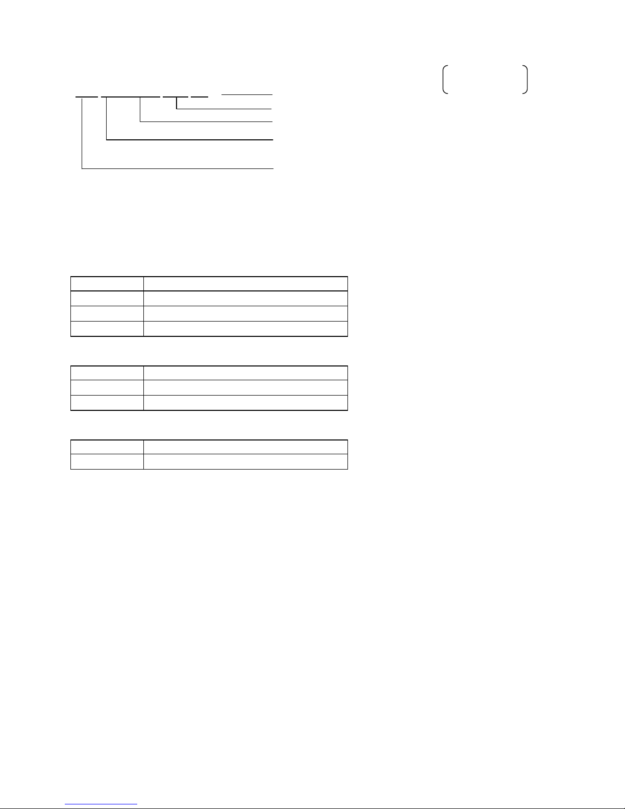
58
RFID module check
RFID
OK#00RV972 (EU0) R01 Module revision (U2 series only)
Destination (U2 series only)
RFID module version
OK: Normal state
NG: Erroneous state
RFID module
Module versions and applicable countries
B-EX700-RFID-U2-US-R
Version Country
R00 US
R01 US, AU, TW
R02 US, AU, KR2, TW
B-EX700-RFID-U2-EU-R
Version Country
R00 EU
R11 EU, IN0
B-EX700-RFID-U2-R
Version Country
R00 JP
JP: Japan
EU0: Europe
US: North America
CN2: China
AU: Australia
KR2: Korea
TW: Taiwan
IN0: India
RFID module
U2 series only
Page 64

59
Wireless LAN mount check
WLAN
NG
OK: Mounted
NG: Not mounted or setting of wireless LAN disabled
Wireless LAN
MAC
00-11-22-33-44-55
Wireless LAN MAC address (Printed only when WLAN is mounted.)
RTC mount check
RTC
NG
OK: Mounted. Print date and time if mounted (YY-MM-DD hh:mm:ss)
NG: Not mounted
RTC
USB memory mount check
USB MEMORY
NG
OK: Mounted
NG: Not mounted
USB memory
BASIC program check
BASIC M
NONE
NONE: No program installed
Version: Program installed
BASIC main program
BASIC S
NONE
NONE: No program installed
Version: Program installed
BASIC system program
Page 65

60
8.3.3 HEAD CHECK
The print head check procedure is the same as that for the maintenance counter data. 8.3.1 MAINTENANCE
CONT.
The following table shows the menu structure from the top menu of the system mode to HEAD CHECK.
MENU ITEM Display pattern and key operatio
n
SYSTEM MODE
<1>DIAG.
7.1 LIST BOX WITH SCROLLBAR
HEAD CHECK
7.3 INFORMATION DISPLAY
While checking
Displays “CHECKING”.
In the case of normal end
Displays “NORMAL END”
When broken dots are detected.
The ONLINE LED turns off and the ERROR LED turns
on.
Displays the number of broken dots in the format of the
number of broken dots out of the total number of dots.
The total number of dots is right-aligned.
Page 66

61
8.4 PARAMETER SET
Contents of the PARAMETER SET menu.
MENU ITEM Display pattern and key operation
SYSTEM MODE
<2>PARAMETER SET
PRINTER SET
SOFTWARE SET
PANEL
PASSWORD
7.1 LIST BOX WITH SCROLLBAR
8.4.1 PRINTER SET
Contents of PRINTER SET submenu.
MENU ITEM Display pattern and key operation
SYSTEM MODE
<2>PARAMETER SET
PRINTER SET
MEDIA LOAD
FORWARD WAIT
7.1 LIST BOX WITH SCROLLBAR
FORWARD WAIT POS. 7.2 VALUE SETTING DISPLAY
FW/BK ACT.
HU CUT/RWD.
RBN SAVE
PRE PEEL OFF
BACK SPEED
7.1 LIST BOX WITH SCROLLBAR
Page 67

62
8.4.1.1 MEDIA LOAD
This function is enabled only when the sensor type is set to other than “None”.
・ OFF Media loading function is disabled (Same as feed by depression of the [FEED] key)
・ STD
When the [FEED] key is pressed after the printer is tuned on, reset in batch mode,
or the print head is closed, the printer detects the next gap/black mark and feeds
the paper from the sensor to the print start position
.
・ ECO
When the [FEED] key is pressed after the printer is tuned on, reset in batch mode,
or the print head is closed, the printer detects the next gap/black mark and feeds
the paper to the print start position based on the last label pitch printed.
・ ECO+Bfeed
After performing the ECO function the printer feeds the paper backward for the
label pitch length while raising the print head if the specified conditions are satisfied.
(See the following conditions.)
Hardware Optional ribbon saving module (solenoid) is installed.
Parameter RBN SAVE parameter is set to TAG or LABEL
Operation Media pitch falls between 20mm and 100mm.
The previous issue mode was Batch. (The issue mode is not
reset by power off or a printer reset.)
Caution Even if the hardware requirement is not satisfied (the optional
ribbon saving module is not installed), the printer feeds the media
backward when the other requirements are satisfied. However,
this operation is not guaranteed as it is outside of the
specification.
8.4.1.2 FORWARD WAIT
・ OFF
Disables the auto forward feed wait
・ ON
Enables the auto forward feed wait
8.4.1.3 FORWARD WAIT POS.
Max.
value
Min. value Step Display Sign Integer
digit
Decimal
place
0-padding Unit of
measure
5.0 -5.0 0.1 Decimal Exist 2 1 None mm
・ + (Plus) Increases the forward feed amount.
・ - (Minus) Decreases the forward feed amount.
NOTES:
1. If the pitch of the media used for the previous issue was less than 20mm, the forward wait will not be
activated regardless of the parameter setting
<Supplement> In the case labels with the different pitch (less than 20mm and 20mm or longer) are
alternately placed in one label roll, the forward wait is not activated for the labels with the pitch of less
than 20mm. Therefore it stays at the print stop position without being fed backward. Before the next label
with the pitch of 20mm or larger is printed, however, it is automatically fed backward along with the
previously printed label. This may cause the print data to be printed on the previous label.
2. The media will stay at the forwarded position even if the power is turned off/on, the printer is reset, or the
print head is opened/closed.
Page 68

63
8.4.1.4 FW/BK ACT.
・ MODE1
The printer waits for next issue with 13.7-mm media forwarded.
・ MODE2
When the thermal transfer method and cut issue are selected, the printer feeds
6-mm media backward, then waits for next issue with 3-mm media forwarded.
NOTE:
From this position, the printer starts the on-the-fly printing for next issue.
The print speed for the 3-mm distance to the home position is limited as
follows.
203-dpi model: 3 ips
305-dpi model: 3 ips
* Except for the multi-step acceleration area for short-pitch labels, the print
speed will be accelerated up to the specified speed when the media has not
been forwarded.
8.4.1.5 HU CUT/RWD.
Whether or not to activate the head up action in the cut issue or to use the Rewinder in the batch or strip
issue is selected.
* The print head may not be raised depending on the rise of the solenoid’s temperature.
・ OFF
Head up cut is not performed or the Rewinder is not used.
・ ON
Head up cut is performed or the Rewinder is used.
8.4.1.6 RBN SAVE
・ TAG
Enabled (When the head lever is set to TAG position)
・ LABEL Enabled (When the head lever is set to Label position)
・ OFF Disabled.
NOTE:
If this setting is enabled without the ribbon saving module not installed, the ribbon slacks and a print failure
occurs. Care must be taken when setting this parameter.
Also, the ribbon saving option shall be selected depending on the head lever position. Incorrect setting
may disable the proper ribbon saving function.
8.4.1.7 PRE PEEL OFF
・ OFF Disables pre peel off
・ ON Enables pre peel off
NOTE:
Pre peel off is automatically enabled when the print speed is set to 10 ips or faster.
However, the print speed is corrected depending on the EX I/O parameter setting, as follows.
▪ EXI/O: TYPE 1 (Standard)
203-dpi model: 10 ips
305-dpi model: 8 ips
▪ EX I/O: TYPE 2 (Inline)
Specified speed
Accordingly, when the print speed is set to 8 ips or less, pre peel off is enabled only when this parameter is
set to ON.
8.4.1.8 BACK SPEED
・ STD 3 ips
・ LOW 2 ips
Page 69
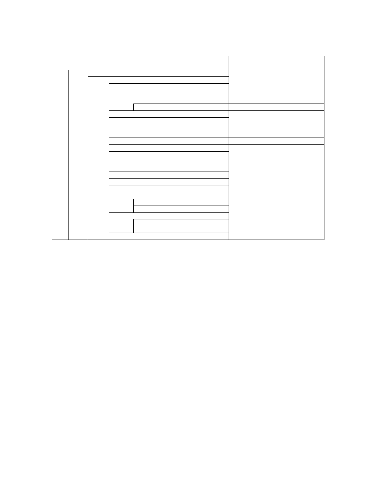
64
8.4.2 SOFTWARE SET
Contents of SOFTWARE SET menu
MENU ITEM Display pattern and key operation
SYSTEM MODE
<2>PARAMETER SET
SOFTWARE SET
FONT CODE
ZERO FONT
CODE
7.1 LIST BOX WITH SCROLLBAR
MANUAL 7.2 VALUE SETTING DISPLAY
PEEL OFF STATUS
USB I/F STATUS
FEED KEY
KANJI CODE
7.1 LIST BOX WITH SCROLLBAR
EURO CODE 7.2 VALUE SETTING DISPLAY
AUTO HD CHK
WEB PRINTER
RBN NEAR END
EX.I/O
LBL/RBN END
MAXI CODE
XML
THRESHOLD SELECT
REFLECT
TRANS.
ENERGY TYPE
TRANSFER
DIRECT
PW SAVE TIME
7.1 LIST BOX WITH SCROLLBAR
Page 70

65
8.4.2.1 FONT CODE
・ PC-850
・ PC-852
・ PC-857
・ PC-8
・ PC-851
・ PC-855
・ PC-1250
・ PC-1251
・ PC-1252
・ PC-1253
・ PC-1254
・ PC-1257
・ LATIN9
・ Arabic
・ PC-866
・ UTF-8
8.4.2.2 ZERO FONT
・ 0 No slash used
・ Ø Slash used
NOTE: The following fonts do not support a zero with a slash. Therefore, even if a zero with a slash
is selected, a zero without a slash is used.
[Bit map fonts]
OCR-A, OCR-B, GOTHIC725 Black, Japanese Kanji, Chinese
[Outline fonts]
Price fonts 1, 2, and 3, DUTCH801 Bold, BRUSH738 Regular, GOTHIC725 Black,
True type font
8.4.2.3 CODE
・ AUTO
・ {,|,}
・ ESC,LF,NUL
・ MANUAL
Page 71

66
8.4.2.4 MANUAL
Max.
value
Min. value Step Display Sign Integer
digit
Decimal
place
0-padding Unit of
measure
0xFF 0x00 1 Hex
decimal
None 2 0 None h
・ CODE1
・ CODE2
・ CODE3
8.4.2.5 PEEL OFF STATUS
・ OFF Disabled
・ ON Enabled
8.4.2.6 USB I/F STATUS
・ OFF
Disables sending a response via USB.
・ ON
Enables sending a response via USB.
8.4.2.7 FEED KEY
・ FEED Feeds one label.
・ PRINT Prints data in the image buffer
8.4.2.8 KANJI CODE
・ TYPE1 Windows code
・ TYPE2 Original code
8.4.2.9 EURO CODE
Max.
value
Min. value Step Display Sign Integer
digit
Decimal
place
0-padding Unit of
measure
0xFF 0x20 1 Hex. None 2 0 None h
8.4.2.10 AUTO HD CHK
・ OFF Disables the auto print head check
・ ON Enables the auto print head check
Page 72

67
8.4.2.11 WEB PRINTER
・ OFF Disables WEB printer function
・ ON INT Enables WEB printer function (Internal memory is used)
・ ON EXT Enables WEB printer function (External memory is used)
8.4.2.12 RBN NEAR END
・ OFF Ribbon near end is not detected.
・ 30m Ribbon near end is detected when the remaining ribbon is 30-m long
(Equivalent to ribbon diameter of 38 mm)
・ 70m Ribbon near end is detected when the remaining ribbon is 70-m long
(Equivalent to ribbon diameter of 43 mm)
NOTE: Since a detected remaining ribbon length has some margin of error, use the specified length as a
guide.
8.4.2.13 EX.I/O
・ TYPE1 Standard specification
・ TYPE2 In-line specification
Page 73

68
8.4.2.14 LBL/RBN END
・ TYPE1 When a label end or ribbon end status is detected, the printer stops immediately.
・ TYPE2 When a label end or ribbon end status is detected, the printer prints the current label as
far as possible, then stops.
TYPE1:
When a label end or ribbon end is detected in the middle of printing, printing is immediately stopped. When
the printing is restarted, first the initial feed is performed, then the printer starts printing from the unfinished
label.
TYPE2:
TYPE 2 is available only when the ribbon saving function is set to OFF. When the ribbon saving is
enabled, TYPE 1 will be automatically performed regardless of the selection.
[Label end]
When a label end is detected in the middle of printing, the printer completes the half-finished label and stops
when the next label is at the home position, displaying the error message “NO PAPER X”. (“X” indicates
the remaining number of labels.) The remaining number of labels = [Specified number of labels] − [The
number of finished labels including half-finished one]
If a label end is detected while the specified last label is printed, the position of “X” will be blank.
When the printing is restarted, first the initial feed is performed, and then the printer starts printing from the
next label. In case of the label end while the specified last label is printed, only the initial feed is performed,
and if the status response is set to ON, an issue end status is sent following a feed end status.
[Ribbon end]
When a ribbon end is detected when the unfinished label length is 30 mm or more, printer prints for 20 mm
and stops printing, displaying an error message “NO RIBBON X”. (“X” indicates the remaining number of
labels.)
The remaining number labels = [Specified number of labels] − [The number of finished labels] − 1
If a ribbon end is detected while the specified last label is printed, the position of “X” will be blank.
When the printing is restarted, first the initial feed is performed, and then the printer starts printing from the
next label. In case of the ribbon end while the specified last label is printed, only the initial feed is
performed.
Page 74

69
Example of TYPE2
[Case 1] Specified number of labels = 5,
A label end is detected while the 3rd label is printed.
(1st)(2nd)(3rd)
↑
After issuing 3rd label completely, the printer stops printing, displaying “NO PAPER 2”.
When printing is restarted, first the initial feed is performed, then 4th and 5th labels are printed.
Finally, all of 5 labels have been finished.
[Case 2] Specified number of labels = 5,
A ribbon end is detected while the 3rd label is printed. Unfinished label length is 30 mm or more.
(1st)(2nd)(3rd)
↑
After the 3rd label is printed for 20 mm, the printer stops printing, displaying “NO RIBBON 2”.
When printing is restarted, first the initial feed is performed, then 4th and 5th labels are printed.
Finally, 1st, 2nd, 4th, and 5th labels have been finished.
[Case 3] Specified number of labels = 5,
A ribbon end is detected while the 3rd label is printed. Unfinished label length is less than 30 mm.
(1st)(2nd)(3rd)
↑
After issuing 3rd label completely, the printer stops printing, displaying “NO RIBBON 2”.
When printing is restarted, first the initial feed is performed, then 4th and 5th labels are printed.
Finally all of 5 labels have been finished.
8.4.2.15 MAXI CODE
・ TYPE1 Compatible with the current version
・ TYPE2 Special specification
The mode specified by the command may be different from the actual mode, depending on the status of this
parameter. Also, the data transmission method differs partly.
For details, refer to the External Equipment Interface Specification (EAA-03466).
8.4.2.16 XML
・ OFF Disables XML function
・ STD Standard specification
・ ORACLE Specification for Oracle
・ SAP Specification for SAP
・ STD EXT Standard specification (external memory is used)
・ ORACLE EXT Specification for Oracle (external memory is used)
・ SAP EXT Specification for SAP (external memory is used)
Page 75

70
8.4.2.17 THRESHOLD SELECT
・ REFLECT Reflective sensor
・ TRANS. Transmissive sensor
8.4.2.17.1 REFLECT
・ MANUAL SET Threshold set in the threshold mode takes effect.
・ COMMAND SET Threshold set by command takes effect.
8.4.2.17.2 TRANS.
・ MANUAL SET Threshold set in the threshold mode takes effect
・ COMMAND SET Threshold set by command takes effect.
8.4.2.18 ENERGY TYPE
This parameter is intended to make the printer perform appropriate printing for the supplies to be used. Use
of a different supply from the setting may cause poor printing.
For details of the appropriate settings, refer to the Supply Specification.
・ TRANSFER
・ DIRECT
8.4.2.18.1 TRANSFER
・ Semi resin1 Semi-resin 1
・ Semi resin2 Semi-resin 2
・ Resin1 Resin 1
・ Resin2 Resin 2
・ Reserve1 to Reserve6 Reserved
8.4.2.18.2 DIRECT
・ Standard Standard
・ Reserve1 to Reserve9 Reserved
8.4.2.19 PW SAVE TIME
Max.
value
Min. value Step Display Sign Integer
digit
Decimal
place
0-padding Unit of
measure
240 1 1 Decimal None 3 0 None Min.
Page 76

71
8.4.3 PANEL
Contents of PANEL menu
MENU ITEM Display pattern and key operation
SYSTEM MODE
<2>PARAMETER SET
PANEL
LCD LANGUAGE
LCDISPLAY
MACHINE NAME
PRINT PAGE
IP ADDRESS
7.1 LIST BOX WITH SCROLLBAR
CONTRAST 7.2 VALUE SETTING DISPLAY
8.4.3.1 LCD LANGUAGE
・ ENGLISH
・ GERMAN
・ FRANCH
・ DUTCH
・ SPANISH
・ JAPANESE
・ ITALIAN
・ PORTUGUESE
The language displayed on panel is Japanese when JAPANESE is selected, and English when English,
German, French, Dutch, Spanish, Italian, or Portuguese is selected.
8.4.3.2 MACHINE NAME
・ OFF Model name is hidden.
・ ON Model name is displayed.
8.4.3.3 PRINT PAGE
・ OFF The number of labels printed is hidden.
・ ON The number of labels printed is displayed.
8.4.3.4 IP ADDRESS
・ OFF IP address is hidden.
・ ON IP address is displayed.
Page 77
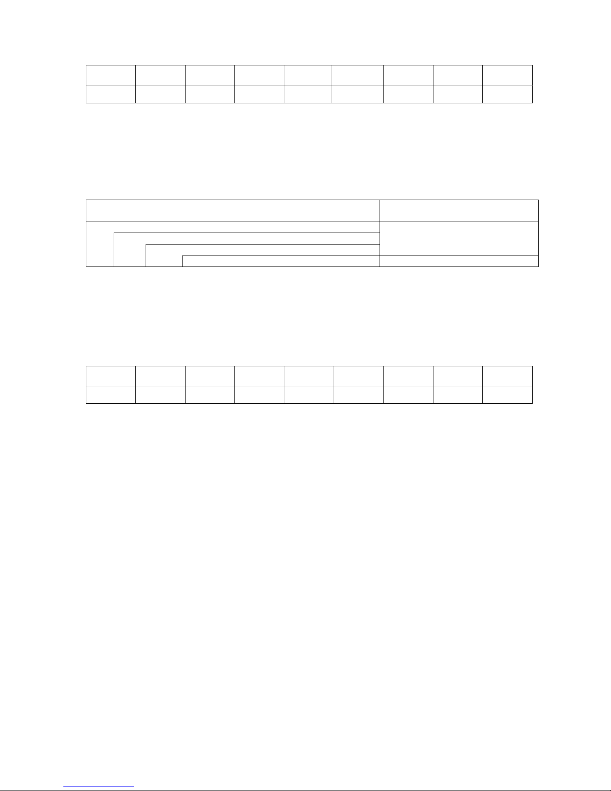
72
8.4.3.5 CONTRAST
Max.
value
Min. value Step Display Sign Integer
digit
Decimal
place
0-padding Unit of
measure
50 24 2 Decimal None 2 0 Enabled None
・ + (Plus) High
・ - (Minus) Low
8.4.4 PASSWORD
Menu structure of PASSWORD menu
MENU ITEM Display pattern and key operatio
n
SYSTEM MODE
<2>PARAMETER SET
PASSWORD
7.1 LIST BOX WITH SCROLLBAR
PASSWORD 7.2 VALUE SETTING DISPLAY
PASSWORD
・ OFF Password is not set.
・ ON Password is set.
PASSWORD
Usable input value for password
Max.
value
Min. value Step Display Sign Integer
digit
Decimal
place
0-padding Unit of
measure
F 0 1 Hex. None 1 0 None None
Page 78
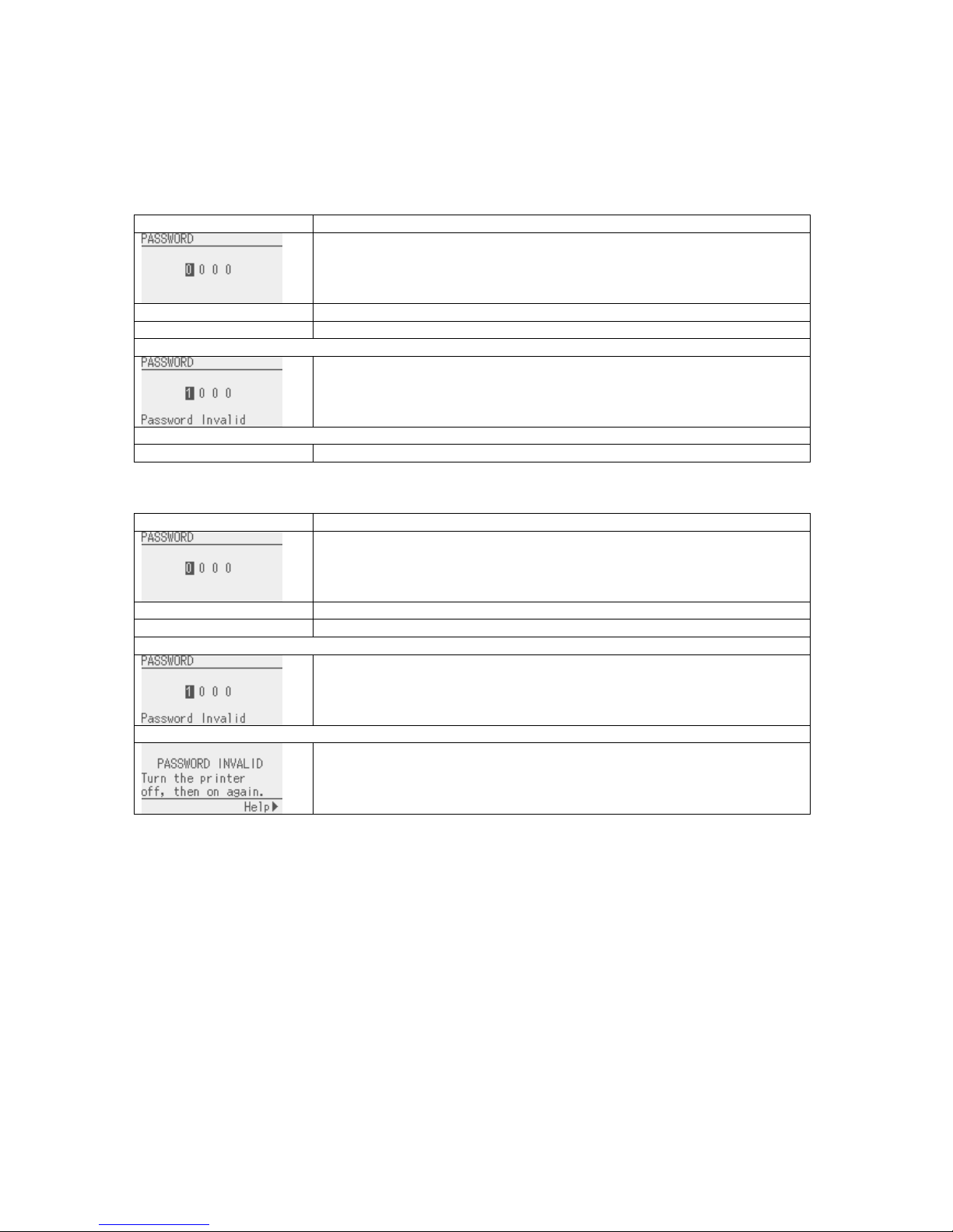
73
8.4.4.1 System mode and user system mode start screen when password is enabled
When the password is enabled, the password input screen is displayed at the time the system mode or user
system mode is started.
Password input for system mode
Display Procedure
Turn on the printer while holding down the [FEED] and [RESTART] keys
at the same time.
The password input screen is displayed.
Input the password.
The printer enters the system mode.
When a wrong password is input or the [CANCEL] key or [MODE] key is pressed
Password invalid message is displayed.
A wrong password was entered consecutively for 3 times.
The printer starts in online mode.
Password input for user system mode
・
・ If you forgot the programmed system mode password, disable it with @010 command.
Display Procedure
Turn on the printer, press the [PAUSE] key to place the printer in pause
state. Then, hold down [RESTART] key or [MODE] key for 3 seconds.
The password input screen is displayed.
Input the password.
The printer enters the user system mode.
When a wrong password is input or the [CANCEL] key or [MODE] key is pressed
Password invalid message is displayed.
A wrong password was entered consecutively for 3 times
The printer locks. Turn off printer and back to on.
Page 79
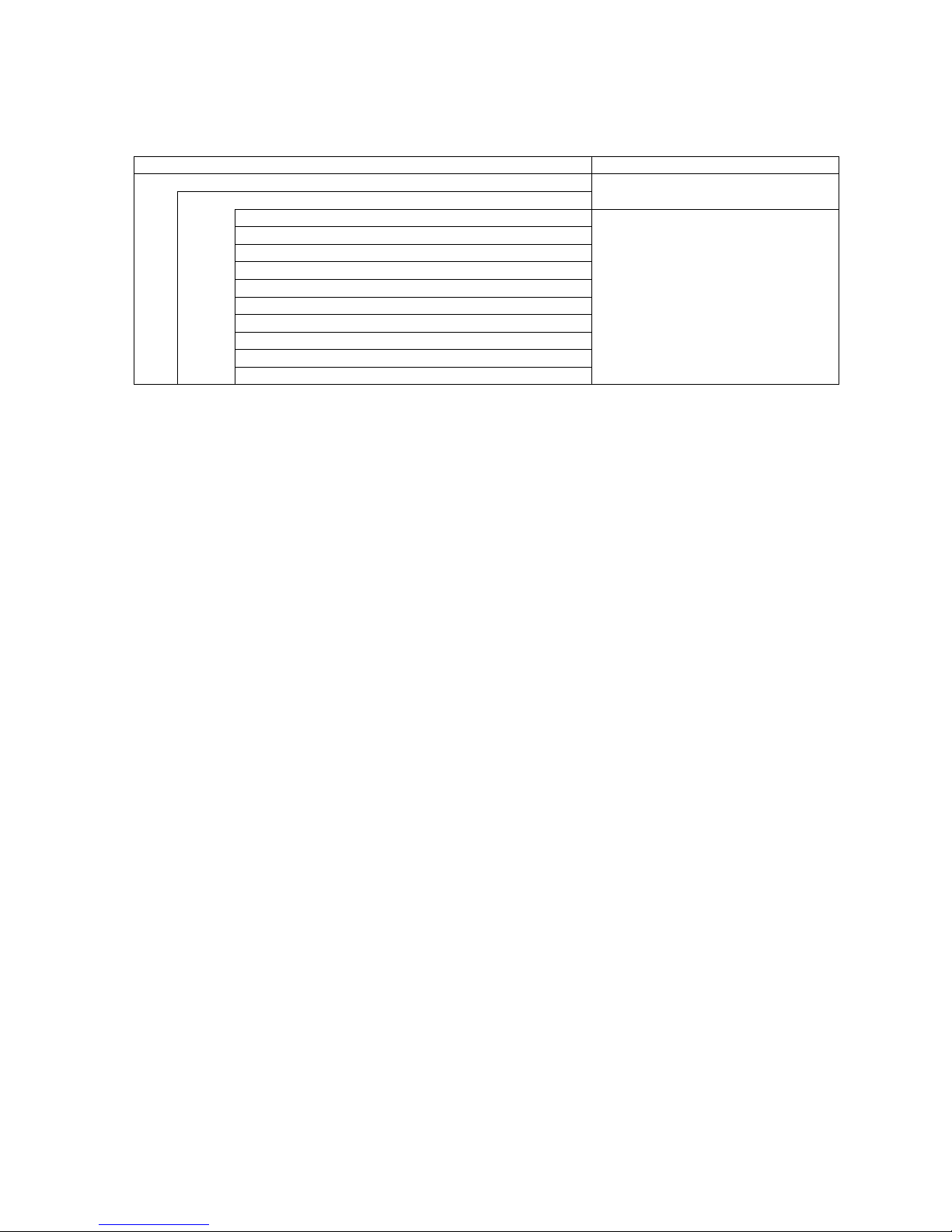
74
8.5 ADJUST SET
Contents of ADJUST SET menu
MENU ITEM Display pattern and key operation
SYSTEM MODE
<3>ADJUST SET
7.1 LIST BOX WITH SCROLLBAR
FEED ADJ.
CUT ADJ.
BACK ADJ.
X ADJUST
TONE ADJ. (TRANS.)
TONE ADJ. (DIRECT)
RBN ADJ.<FW>
RBN ADJ.<BK>
THRESHOLD <REFL.>
THRESHOLD <TRANS.>
7.2 VALUE SETTING DISPLAY
Page 80
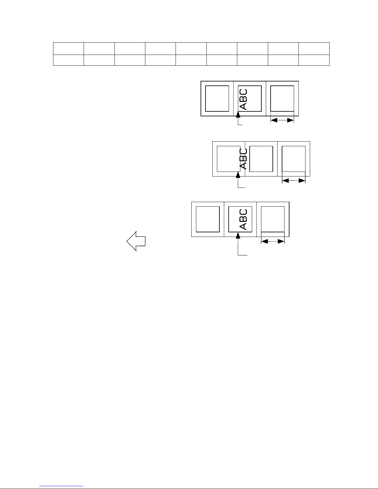
75
8.5.1 FEED ADJ.
Max.
value
Min. value Step Display Sign Integer
digit
Decimal
place
0-padding Unit of
measure
50.0 -50.0 0.1 Decimal Exist 2 1 None mm
NOTE:
A value which is larger than the media pitch (FEED ADJ. ≥ Media pitch) must not be set. If the set fine
adjustment value causes the printer to feed the media backward from the print stop position to the next print
start position, the printer operation is not guaranteed.
+0.0 mm
+3.0 mm
Print start
position
One label
One label
Print start
position
-3.0 mm
One label
Print start position
Paper feed direction
Page 81

76
8.5.2 CUT ADJ
Max.
value
Min. value Step Display Sign Integer
digit
Decimal
place
0-padding Unit of
measure
50.0 -50.0 0.1 Decimal Exist 2 1 None mm
[Procedure for label having label pitch of less than 25.4 mm when the disc cutter is used]
The minimum label pitch of the label which can be cut in normal use is 25.4 mm. When a label
having a label pitch of less than 25.4 mm is used (although it is out of specifications), the edge of the
label is caught by the edge of the thermal head during a back feed to the home position after cutting
the gap area between labels. Therefore, the label may not be fed back to the proper home
position. By performing either method below, the problem will be solved.
[Method 1] Lift the head.
When the following conditions are all met, the cut operation is as follows.
Head lifted → Forward feed to the cut position → Head lowered → Cut →
Head lifted → Reverse feed to the home position → Head lowered
Conditions: Issue Command, Feed Command, and Eject Command received.
Label pitch of 25.4 mm or less, cut performed, transmissive sensor
designated, cut position fine adjustment of ±10.0 mm or less, and issue
mode “C”
* The head is lifted/lowered only when the optional ribbon saving module is mounted
and the ribbon saving function is set to ON with the parameter setting menu. When
the ribbon saving module is not installed, use Method 2 since the print head is not
lifted/lowered.
+0.0 mm
+3.0 mm
-3.0 mm
Cut position
Paper feed direction
Cut position
Cut position
Page 82

77
NOTES: 1. If the bottom edge of the last label advances past the feed roller while the
print head is lifted during label feed to cut, the sensor may not be able to
detect an error even if the label cannot be fed any more.
2. If the head-up solenoid temperature is high when a cut issue is about to be
performed with the head lifted, the head may not be lifted.
[Method 2] Adjust the cut position fine adjustment value.
When this procedure is used, one or more printed labels are left between the head and
the cutter. Therefore, these labels need to be removed by an issue or a label feed.
(a) Cut position fine adjustment value calculation
The cut position fine adjustment value can be calculated using the following method.
If a back feed to the proper home position cannot be performed using this value, the
cut position needs to be adjusted with any value.
Ex) Label pitch: 30.0 mm
Label pitch
(Label pitch)
32.8 mm
* Any decimal remainders are
rounded off.
× (Label pitch)
Cut position fine
adjustment value
=
=
(Number of labels left
between head and cutter)
×
32.8 mm
30.0 mm
× (30.0 mm)
Cut position fine
adjustment value
=
= 1 × 30.0 mm
= +30.0 mm
Page 83
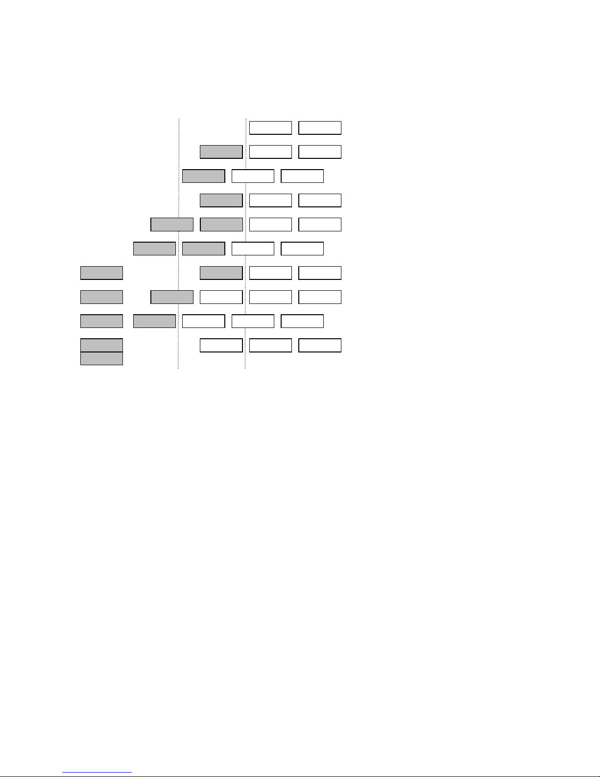
78
(1) Idling
(2) Completes printing the first label (A).
(3) Feeds the label to the cut position, then
cuts the gap in front of label (A).
(4) Back feeds to the home position.
(5) Completes printing the second label
(B).
(6) Feeds the label to the cut position, then
cuts the gap in front of label (B).
(7) Back feeds to the home position.
(8) To eject label (B), feeds the third label
(C).
(9) Feeds the label to the cut position, then
cuts the gap at the front of label (C).
(10) Back feed to the home position.
(b)Operation example
Issue count: 2, Cut interval = 1
Cut position Head position
▼ ▼
A B
A B
A B
C
C
A B C
A B C
A B C
A B C
B
B
B
A
A
A
C
C
C
Page 84

79
[Procedure for label having less than the min. label pitch for each issue speed when the rotary cutter
is used]
When the following conditions are all met, the cut operation for the last label to be cut is as follows.
Forward feed to the cut position → Cut while feeding → Feed stops →
Head lifted → Reverse feed to the home position → Head lowered
Conditions: Issue Command, Feed Command, and Eject Command received.
Label pitch: Less than the min. label pitch for each issue speed,
cut performed, transmissive sensor designated, cut position fine adjustment
of ±10.0 mm or less, and issue mode “C”
* For the Issue Command, this procedure is effective only when the next Issue
Command is not received at the last label to be cut.
* The print head is lifted/lowered only when the optional ribbon saving module is
mounted and the ribbon saving function is set to ON with the parameter setting menu.
When the ribbon saving module is not installed, the print head is not lifted or lowered.
NOTES: 1. If the bottom edge of the last label advances past the feed roller while the
print head is lifted during label feed to cut, the sensor may not be able to
detect an error even if the label cannot be fed any more.
2. If the head-up solenoid temperature is high when a cut issue is about to
be performed with the head lifted, the head may not be lifted
.
Page 85

80
[Strip position fine adjustment]
0.0mm
+3.0mm
-3.0mm
4mm
3mm
▼
2mm
Printing in strip issue mode is stopped at the position
where the distance from the middle point of the gap
between labels to the end of the strip shaft is 4 mm,
since the gap between labels is assumed to be 2 mm.
When the print stop position is not proper due to a
greater gap, the print stop position should be adjusted
using the strip position fine adjust function.
Page 86
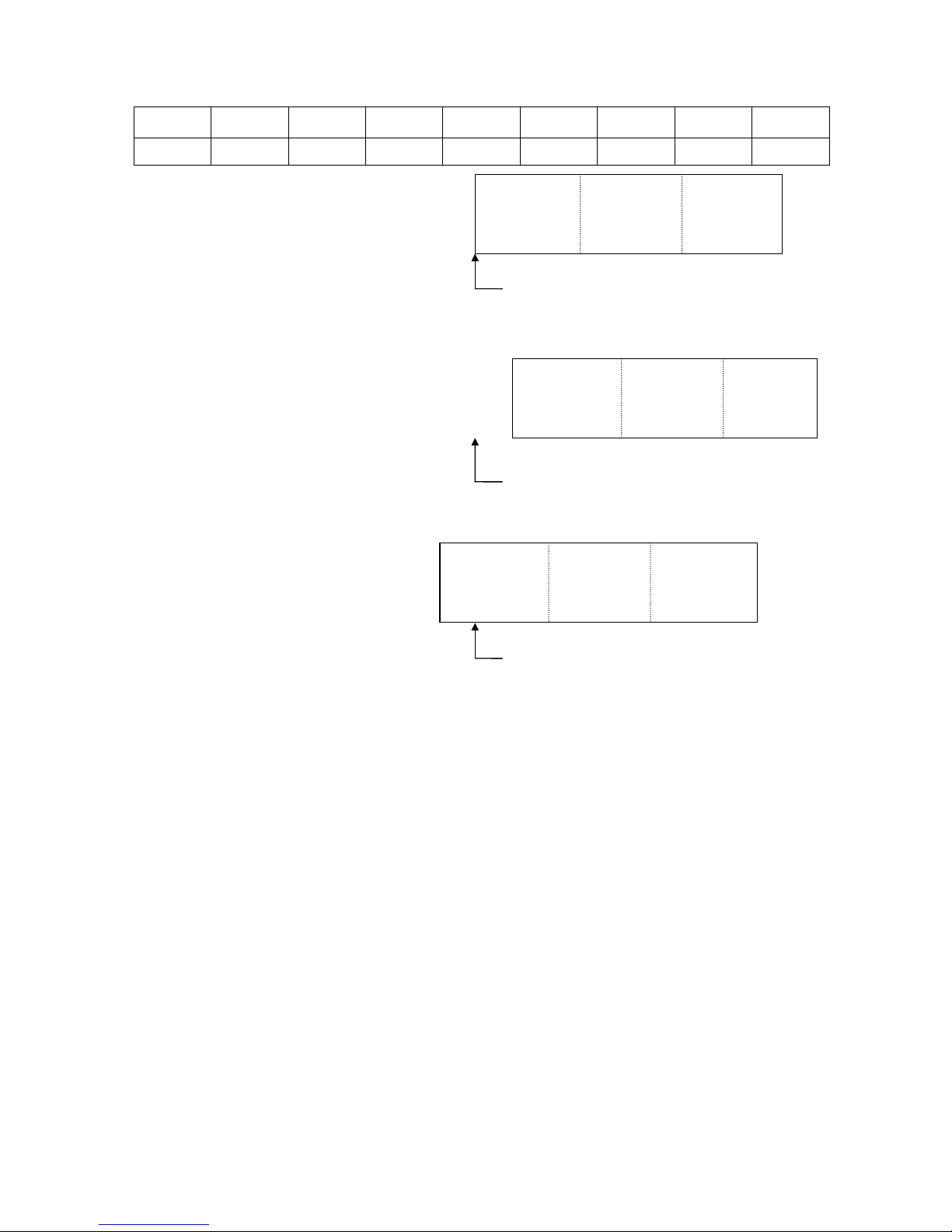
81
8.5.3 BACK ADJ.
Max.
value
Min. value Step Display Sign Integer
digit
Decimal
place
0-padding Unit of
measure
9.9 -9.9 0.1 Decimal Exist 1 1 None mm
+0.0mm
+3.0mm
-3.0mm
NOTE: There may be cases where a label is not returned to the home position depending on the print
conditions, even if a back feed, of which length is the same as the forward feed, is performed.
In issues where any paper sensor is used, if the label pitch length is almost the same as the
distance between the thermal print head and the paper sensors (75.5 mm), a label/tag may not
be returned to the home position when operations with a back feed (such as cut issues, strip
issues, automatic forward feed standby) are performed. It may result in an error. In such
cases, to prevent an error from occurring, the back feed length should be increased by
performing the back feed fine adjustment in the + direction.
Print start position
(Home position after a back feed)
Print start position
(Home position after a back feed)
Print start position
(Home position after a back feed)
Page 87
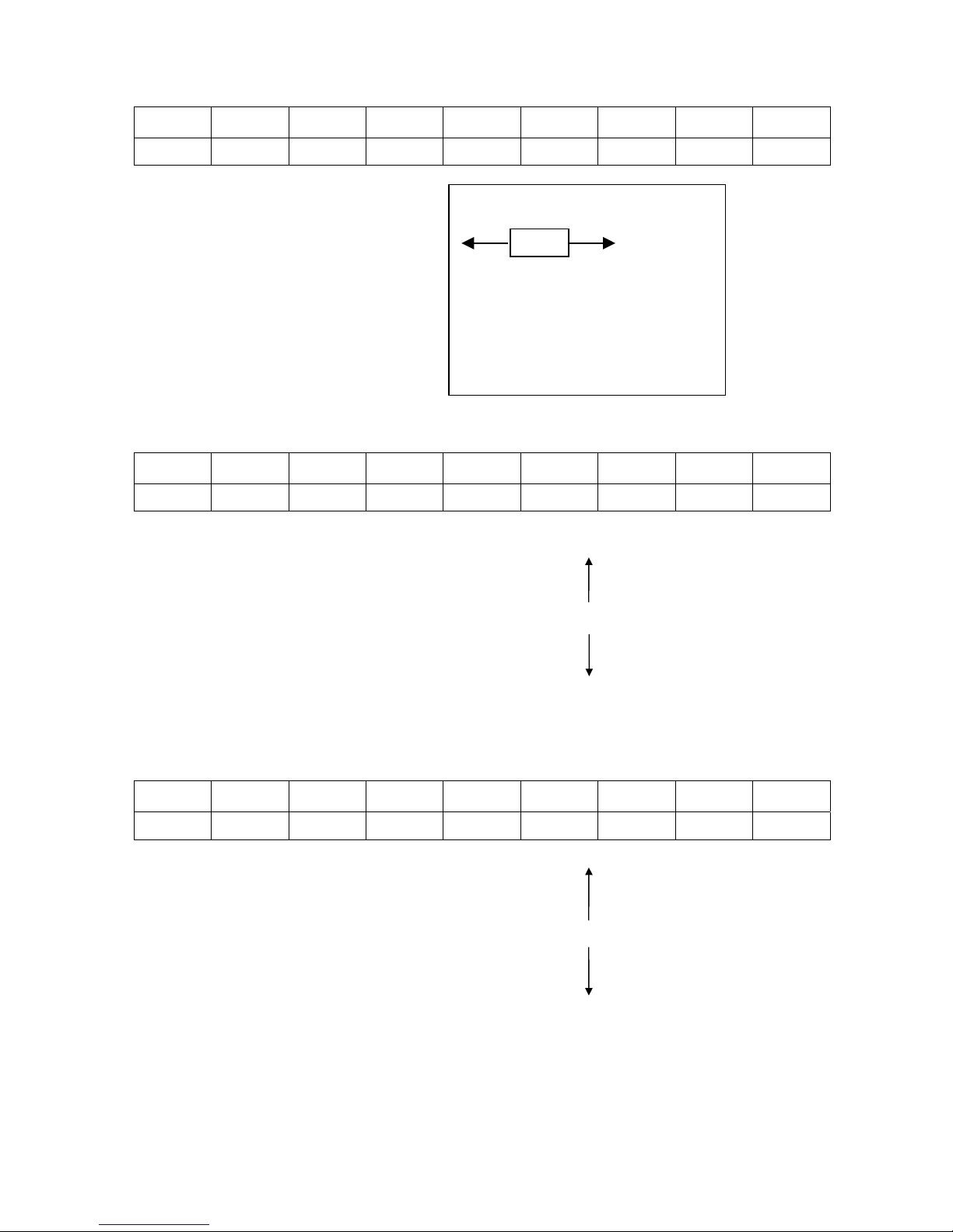
82
8.5.4 X ADJUST
Max.
value
Min. value Step Display Sign Integer
digit
Decimal
place
0-padding Unit of
measure
99.5 -99.5 0.1 Decimal Exist 2 1 None mm
8.5.5 TONE ADJ. (TRANS.)
Max.
value
Min. value Step Display Sign Integer
digit
Decimal
place
0-padding Unit of
measure
10 -20 1 Decimal Exist 2 0 None Step
8.5.6 TONE ADJ. (DIRECT)
Max.
value
Min. value Step Display Sign Integer
digit
Decimal
place
0-padding Unit of
measure
10 -20 1 Decimal Exist 2 0 None Step
+10step Darker
+9step
:
+1step
+0step Standard
-1step
:
-19step
-20step Lighter
+10step Darker
+9step
:
+1step
+0step Standard
-1step
:
-19step
-20step Lighter
X Y Z
–+
Page 88

83
8.5.7 RBN ADJ.<FW>
Max.
value
Min. value Step Display Sign Integer
digit
Decimal
place
0-padding Unit of
measure
10 -15 1 Decimal Exist 2 0 None Step
The fine adjustment value is not effective for the reverse rotation.
The fine adjustment value for the ribbon take-up motor is limited depending on the print speed.
Print speed All speeds 8 ips or less 6 ips or less
Fine adjustment value -15 to 0 +1 to +5 +6 to +10
8.5.8 RBN ADJ.<BK>
Max.
value
Min. value Step Display Sign Integer
digit
Decimal
place
0-padding Unit of
measure
10 -15 1 Decimal Exist 2 0 None Step
The fine adjustment value is not effective for the reverse rotation.
All fine adjustment values are applicable to every print speed.
8.5.9 THRESHOLD <REFL.>
Max.
value
Min. value Step Display Sign Integer
digit
Decimal
place
0-padding Unit of
measure
4.0 0.0 0.1 Decimal None 1 1 None V
NOTE: If “0.0 V” is set, the value “0.0 V” is returned to the initial value (1.0 V) when the power is turned OFF
then ON.
8.5.10 THRESHOLD <TRANS.>
Max.
value
Min. value Step Display Sign Integer
digit
Decimal
place
0-padding Unit of
measure
4.0 0.0 0.1 Decimal None 1 1 None V
NOTE: If “0.0 V” is set, the value “0.0 V” is returned to the initial value (1.4 V) when the power is turned OFF
then ON.
Supplementary explanation
• When the [RESTART] and [FEED] keys are pressed at the same time, the display returns to the system
mode menu.
• When the [RESTART] or [FEED] key is held down for 0.5 seconds or more when a fine adjustment value
is being set, the printer enters the repeat mode, in which the key is entered repeatedly.
• A changed fine adjustment value is stored in memory by pressing the [PAUSE] key.
Page 89

84
• The printer is controlled by the sum of the fine adjustment parameter programmed on the printer and the
fine adjustment command from the PC. However, the maximum values for each fine adjustment are as
follows:
Feed fine adjustment .......................................................................±50.0 mm
Strip position fine adjustment .......................................................... ±50.0 mm
Back feed fine adjustment ................................................................. ±9.9 mm
Print density fine adjustment ........................................... -20 step to ±10 step
X-coordinate fine adjustment........................................................... ±99.5 mm
Ribbon motor drive voltage fine adjustment (Take-up) ...........-15 to +10 step
Ribbon motor drive voltage fine adjustment (Back tension).... -15 to +10 step
• The X-coordinate fine adjustment is performed to fine adjust the X-coordinate of the drawing in the left or
right direction. Adjust the X-coordinate in the effective print range. (After the value reaches the
coordinate “0”, the value remains unchanged even if a subsequent fine adjustment is performed in the
negative direction.)
• The X-coordinate fine adjustment is not effective for the self-test results printout (maintenance counter,
various parameters, and automatic self-test) and the test print.
• The print density fine adjustment value is +0 step at the time of shipment from the factory.
• The ribbon take-up/back tension motors drive voltage fine adjustment values are the sum of the fine
adjustment by the command (from the PC) and the fine adjustment in the system mode (by key
operation). The maximum fine adjustment values are -15 for both the ribbon take-up motor and the
ribbon back tension motor.
• The print density fine adjustment value is the sum of the fine adjustment by command (from the PC) and
the fine adjustment in the system mode (by key operation). The respective max. Fine adjustment values
are –20 to +10. The max value for each print speed is as below. When the value exceeds the
maximum, it is automatically corrected to the max value.
B-EX4T1-G B-EX4T1-T
Speed Direct thermal Thermal transfer Direct thermal Thermal transfer
3 ips +10 step +10 step +10 step +10 step
5 ips +10 step +10 step
6 ips +10 step +10 step
8 ips +10 step +10 step
10 ips +10 step +10 step +10 step +10 step
12 ips +10 step +10 step +10 step +10 step
14 ips +10 step +10 step +10 step +10 step
Page 90
85
8.6 TEST PRINT
Contents of TEST PRINT menu
MENU ITEM Display pattern and key operation
SYSTEM MODE
<4>TEST PRINT
7.1 LIST BOX WITH SCROLLBAR
PRINT CONDITION
ISSUE COUNT
PRINT SPEED
SENSOR
PRINT TYPE
ISSUE TYPE
LABEL PITCH 7.2 VALUE SETTING DISPLAY
PAPER FEED 7.1 LIST BOX WITH SCROLLBAR
SLANT LINE (1DOT) 7.3 INFORMATION DISPLAY
SLANT LINE (3DOT)
CHAACTERS
BARCODE
NON-PRINTING
FACTORY TEST
AUTO PRINT (TRANS.)
AUTO PRINT (REFL.)
8.6.1 PRINT CONDITION
This menu enables setting print conditions for test print.
8.6.1.1 ISSUE COUNT
・ 1
・ 3
・ 5
・ 10
・ 50
・ 100
・ 500
・ 1000
・ 5000
Page 91

86
8.6.1.2 PRINT SPEED
Selectable printer speed differs depending on the resolution.
B-EX4T TYPE 1 B-EX4T TYPE 2 B-EX6T
203dpi 305dpi 203dpi 300dpi 600dpi 203dpi 300dpi
3ips
6ips
10ips
12ips
14ips
3ips
5ips
8ips
10ips
12ips
14ips
3ips
6ips
10ips
12ips
3ips
5ips
8ips
10ips
12ips
2ips
3ips
4ips
5ips
6ips
3ips
6ips
10ips
3ips
5ips
8ips
10ips
When the peel-off is selected for the issue mode, the maximum speed is limited to 10 ips.
8.6.1.3 SENSOR
・ NONE
・ TRANS.
・ REFLECT
・ MANUAL TRANS.
・ MANUAL REFL.
8.6.1.4 PRINT TYPE
・ TRANSFER
・ DIRECT
8.6.1.5 ISSUE TYPE
・ NO CUT
・ WITH CUT
・ PEEL OFF
8.6.1.6 LABEL PITCH
Max.
value
Min. value Step Display Sign Integer
digit
Decimal
place
0-padding Unit of
measure
999 0 1 Decimal None 3 0 None mm
8.6.1.7 PAPER FEED
・ NO FEED
・ FEED
Page 92

87
Initial values when turning the power on
ISSUE COUNT 1 piece
203 dpi: 6”/sec.
300 dpi/305 dpi: 5”/sec.
PRINT SPEED
600 dpi: 3”/sec.
SENSOR Transmissive sensor
PRT TYPE
Thermal transfer
TYPE Batch issue
LABEL LEN. 76 mm
PAPER Enabled
Supplementary explanation:
・ Each fine adjustment parameter is effective for test print. However, the X-coordinate fine adjustment is
excluded.
・ When an error occurs during a test print, the error message is displayed and printing is stopped. The
error LED turns on and the online LED turns off.
・ The error is cleared by a depression of the [CANCEL] key or [ENTER] key, and the display returns to the
test print menu. The error LED turns off and the online LED turns on. Printing is not automatically
resumed after the error is cleared.
・ The label size greater than the image buffer length cannot be designated. If it is designated, the printer
prints data corresponding to the image buffer length then stops, or the printer stops because of an error.
・ When the transmissive sensor is selected, the gap between labels shall be 3 mm.
For the B-EX4, the rotary cutter does not support the print speed of 10 ips or faster. When the rotary cutter is
mounted (regardless of the cut issue is specified), the print speed is corrected to 8 ips even if 10 ips is
selected.
For B-EX4T1-G, specifying less than 15.0-mm pitch label for 3 ips print speed or less than 30.0-mm pitch label
for 6 ips, printing is performed without cut.
For B-EX4T1-T, specifying less than 15.0-mm pitch label for 3 ips print speed, less than 25.0-mm pitch label
for 5 ips, or less than 38.0-mm pitch label for 8 ips, printing is performed without cut.
.
Page 93
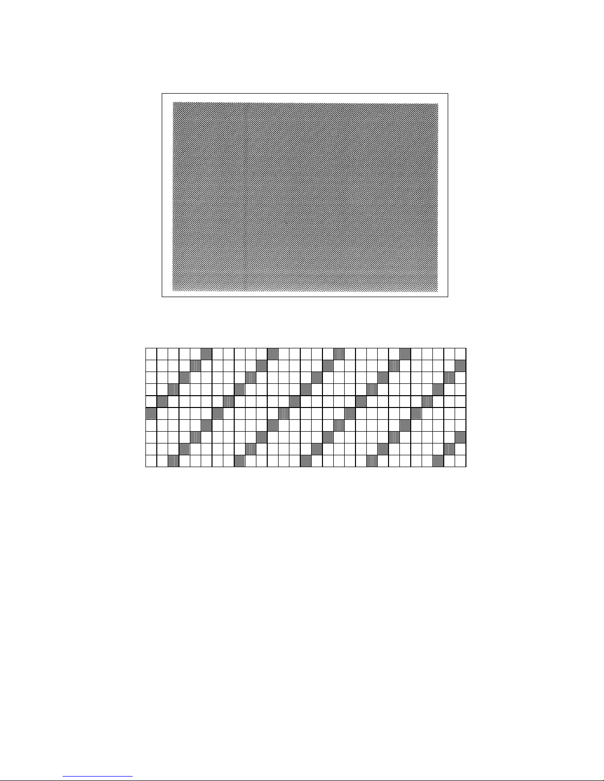
88
8.6.2 SLANT LINE (1DOT)
1-dot slant line
Magnification of slant line
1-dot slant line (Black area ratio: 16.7%)
Page 94

89
8.6.3 SLANT LINE (3DOT)
3-dot slant line
Magnification of slant line
3-dot slant line (Black area ratio: 16.7%)
Page 95
90
8.6.4 CHARACTERS
Gothic + Mincho
Gothic + Chinese
Page 96

91
8.6.5 BARCODE
8.6.6 NON-PRINTING
The printer feeds blank label.
8.6.7 FACTORY TEST
Page 97

92
8.6.8 AUTO PRINT (TRANS.)
The factory test print is performed on the following conditions. The parameter settings and the print density
fine adjustment value are ignored.
• After each test pattern is printed, the factory test print is performed when the [ENTER] key (or its
compatible key) is pressed.
• When the [CANCEL] key (or its compatible key) is pressed, the display returns to the menu.
• Other keys are invalid.
Feeding 1 label
Printing 3-dot slant lines
Printing barcode
Print test pattern
Printing characters
Issue count 5 labels each
203 dpi: 6”/sec.
300 dpi/305dpi: 5”/sec.
Print speed
600 dpi: 3”/sec.
Sensor type Transmissive sensor
Print method Thermal transfer
Issue mode Continuous issue
Label pitch 76 mm
Print density fine adjustment value ±0
8.6.9 AUTO PRINT (REFL.)
The factory test print is performed on the following conditions. The parameter settings and the print density
fine adjustment value are ignored.
• After each test pattern is printed, the factory test print is performed when the [ENTER] key (or its
compatible key) is pressed.
• When the [CANCEL] key (or its compatible key) is pressed, the display returns to the menu.
• Other keys are invalid.
Feeding 1 label
Printing 3-dot slant lines
Printing barcode
Print test pattern
Printing characters
Issue piece5 pieces each 5 labels each
203 dpi: 6”/sec.
300 dpi/305dpi: 5”/sec.
Print speed
600 dpi: 3”/sec.
Sensor type Transmissive sensor
Print method Thermal transfer
Issue type Continuous issue
Label pitch 76 mm
Print density fine adjustment value ±0
Page 98

93
8.7 SENSOR ADJUST
Contents of SENSOR ADJUST menu
MENU ITEM Display pattern and key operation
SYSTEM MODE
<<5>SENSOR ADJUST
7.1 LIST BOX WITH SCROLLBAR
TEMPERATURE 7.5 TEMPERATURE DISPLAY
REFLECT 7.4 SENSOR ADJUSTMENT
DISPLAY
TRANS.
PE REFL./TRANS.
RIBBON
8.7.1 TEMPERATURE
The ambient temperature and print head temperature are displayed.
Only when the temperature is below zero, the symbol of minus (-) is displayed.
The display is updated every 200 msec.
The range of each temperature is below.
Ambient temperature -20 to 100
Print head temperature -20 to 100
8.7.2 REFLECT
The sensor level of the reflective sensor is registered.
Place the tag paper to be used on the reflective sensor so that the sensor can detect a print area. .
The display of the currently detected value is updated every 200 msec.
Hold down the [ENTER] key for 3 seconds or more.
When the registration of the “print area level” is completed, “Adjustment Complete” is displayed and an
asterisk (*) is shown on the right side of the voltage.
If the adjustment failed due to sensor failure, “SENSOR ERROR” is displayed and the ERROR LED turns on.
The ERROR LED turns off when the upper hierarchy menu is displayed.
The setting range is as below.
Reflective sensor 0.0V to 5.0 V
8.7.3 TRANS.
The sensor level of the transmissive sensor is registered.
Remove some labels and place the backing paper so that the Transmissive sensor can detect it.
The display of the currently detected value is updated every 200 msec.
Hold down the [ENTER] key for 3 seconds or more.
When the registration of the “label gap level” is completed, “Adjustment Complete” is displayed and an
asterisk (*) is shown on the right side of the voltage.
If the adjustment failed due to sensor failure, “SENSOR ERROR” is displayed and the ERROR LED turns on.
The ERROR LED turns off when the upper hierarchy menu is displayed.
The setting range is as below.
Transmissive sensor 0.0V to 5.0 V
Page 99

94
8.7.4 PE REFL./TRANS.
Paper end level of the transmissive sensor and the reflective sensor is registered.
Remove any media from the media sensor.
The display of the currently detected value is updated every 200 msec.
Hold down the [ENTER] key for 3 seconds or more.
When the registration of the “paper end level” is completed, “Adjustment Complete” is displayed and an
asterisk (*) is shown on the right side of the voltage.
If the adjustment failed due to sensor failure, “SENSOR ERROR” is displayed and the ERROR LED turns on.
The ERROR LED turns off when the upper hierarchy menu is displayed.
The setting range is as below.
Reflective sensor 0.0V to 5.0 V
Transmissive sensor 0.0V to 5.0 V
8.7.5 RIBBON
Ribbon level is registered.
Set the ribbon so that the ribbon end sensor can detect a ribbon area.
The display of the currently detected value is updated every 200 msec.
Hold down the [ENTER] key for 3 seconds or more.
When the registration of the “ribbon level” is completed, “Adjustment Complete” is displayed and an asterisk
(*) is shown on the right side of the voltage.
If the adjustment failed due to sensor failure, “SENSOR ERROR” is displayed and the ERROR LED turns on.
The ERROR LED turns off when the upper hierarchy menu is displayed.
The setting range is as below.
Ribbon end sensor 0.0V to 5.0 V
Page 100

95
8.8 RAM CLEAR
Contents of RAM CLEAR menu
MENU ITEM Display pattern and key operation
SYSTEM MODE
<6>RAM CLEAR
NO RAM CLEAR
MAINTE.CNT CLEAR
ALL COUNTER
FEED
PRINT
CUT
OTHER
PARAMETER CLEAR
QM TYPE
JA TYPE
CN TYPE
7.1 LIST BOX WITH SCROLLBAR
8.8.1 NO RAM CLEAR
This option is provided for users who access this menu by mistake, and intended to exit from the RAM clear
menu without performing any RAM clear.
8.8.2 MAINTE.CNT CLEAR
The maintenance counter, including label distance covered, is cleared.
Initial value after maintenance counter clear
Item Initial value
Label distance covered 0 km
Print distance 0 km
Cut count 0
Head up/down count 0
Ribbon motor drive time 0 hours
Head-up solenoid driver time 0 hours
RS-232C hardware error count 0
System error count 0
Momentary power interruption count 0
Display
While clearing
After the maintenance counter clear is
completed
Turn off the printer when “COMPLETED. Turn off the printer” is displayed after the RAM clear is completed.
 Loading...