

Page 1
TOSHIBA Barcode Printer
B-EX4T1 SERIES
Owner’s Manual
Mode d’emploi
Bedienungsanleitung
Manual de instrucciones
Gebruikershandleiding
Manuale Utente
Manual do Utilizador
Page 2
A
CE Compliance (for EU only)
This product complies with the requirements of EMC and Low Voltage Directives including their
amendments.
VORSICHT:
• Schallemission: unter 70dB (A) nach DIN 45635 (oder ISO 7779)
• Die für das Gerät Vorgesehene Steckdose muß in der Nähe des Gerätes und leicht zugänglich sein.
Centronics is a registered trademark of Centronics Data Computer Corp.
Microsoft is a registered trademark of Microsoft Corporation.
Windows is a trademark of Microsoft Corporation.
This equipment has been tested and found to comply with the limits for a Class A digital device,
pursuant to Part 15 of the FCC Rules. These limits are designed to provide reasonable rotection
against harmful interference when the equipment is operated in a commercial environment. This
equipment generates, uses, and can radiate radio frequency energy and, if not installed and sed in
accordance with the instruction manual, may cause harmful interference to radio communications.
Operations of this equipment in a residential area is likely to cause harmful interference in which case
the user will be required to correct the interference at his own expense.
Changes or modifications not expressly approved by manufacturer for compliance could void the
user’s authority to operate the equipment.
“This Class A digital apparatus meets all requirements of the Canadian Interference-Causing
Equipment Regulations.”
“Cet appareil numérique de la classe A respecte toutes les exigences du Règlement sur le matériel
brouilleur du Canada.”
(for USA only)
(for CANADA only)
N258
IP20
< For EU Only >
TOSHIBA TEC Europe Retail Information Systems S.A.
Rue de la Célidée 33 BE-1080 Brussels
Copyright © 2011
by TOSHIBA TEC CORPORATION
ll Rights Reserved
570 Ohito, Izunokuni-shi, Shizuoka-ken, JAPAN
Page 3

TOSHIBA Barcode Printer
B-EX4T1 SERIES
Owner's Manual
Page 4

Waste Recycling information for users:
Following information is only for EU-member states:
The use of the crossed-out wheeled bin symbol indicates that this product
may not be treated as general household waste.
By ensuring this product is disposed of correctly you will help prevent
potential negative consequences for the environment and human health, which could
otherwise be caused by inappropriate waste handling of this product. For more detailed
information about the take-back and recycling of this product, please contact your supplier
where you purchased the product.
Page 5

Precautions for Handling of Wireless Communication Devices
Wireless LAN Module: SD-Link 11g
RFID Module: TEC-RFID-EU1 (B-EX700-RFID-H1-QM-R), TRW-USM-01 (B-EX700-RFID-U2-US-R),
TRW-EUM-01 (B-EX700-RFID-U2-EU-R), TRW-CNM-01 (B-EX700-RFID-U2-CN-R)
For Europe
This device was tested and certified by Notified Body.
Hereby, Toshiba TEC Corporation, declares that this device is in compliance with the essential requirements and
other relevant provisions of Directive 1999/5/EC.
This equipment uses the radio frequency band which has not been harmonized throughout all EU and EFTA
countries, and can be used in the following countries.
Austria, Belgium, Bulgaria, Cyprus, Czech Republic, Denmark, Estonia, Finland, France, Hungary, Germany,
Greece, Ireland, Italy, Latvia, Lithuania, Luxembourg, Malta, Netherlands, Poland, Portugal, Romania, Slovakia,
Slovenia, Spain, Sweden, United Kingdom, Norway, Liechtenstein, Iceland, Switzerland
For USA
This device complies with Part 15 of the FCC Rules.
Operation is subject to the following two conditions:
(1) this device may not cause harmful interference, and
(2) this device must accept any interference received , including interference that may cause undesired
operation.
Changes or modification not expressly approved by manufacturer for compliance could void the user’s authority
to operate the equipment.
For Canada
Operation is subject to the following two conditions:
(1) this device may not cause interference, and
(2) this device must accept any interference , including interference that may cause undesired operation of the
device.
For Taiwan
Caution
根據低功率電波輻射性電機管理辦法
For safety
Do not use this product in locations where use may be forbidden, for example, in an aeroplane or a hospital. If
you do not know the forbidden areas, please refer to and follow the airline company or medical institution
guidelines.
Otherwise, flight instrument or medical equipment may be affected, causing a serious accident.
This product may affect the operation of some implanted cardiac pacemakers and other medically implanted
equipment. Pace maker patients should be aware that the use of this product very close to a pacemaker might
cause the device to malfunction.
If you have any reason to suspect that interference is taking place, immediately turn off the product and contact
your TOSHIBA TEC sales agent.
Do not disassemble, modify, or repair the product.
Doing so may cause injury. Also, modification is against the Laws and Regulations for Radio Equipment. Please
ask your TOSHIBA TEC sales agent for repair.
Page 6
Safety Summary ENGLISH VERSION
W
Safety Summary
Personal safety in handling or maintaining the equipment is extremely important. Warnings and Cautions
necessary for safe handling are included in this manual. All warnings and cautions contained in this manual
should be read and understood before handling or maintaining the equipment.
Do not attempt to effect repairs or modifications to this equipment. If a fault occurs that cannot be rectified
using the procedures described in this manual, turn off the power, unplug the machine, then contact your
authorised TOSHIBA TEC representative for assistance.
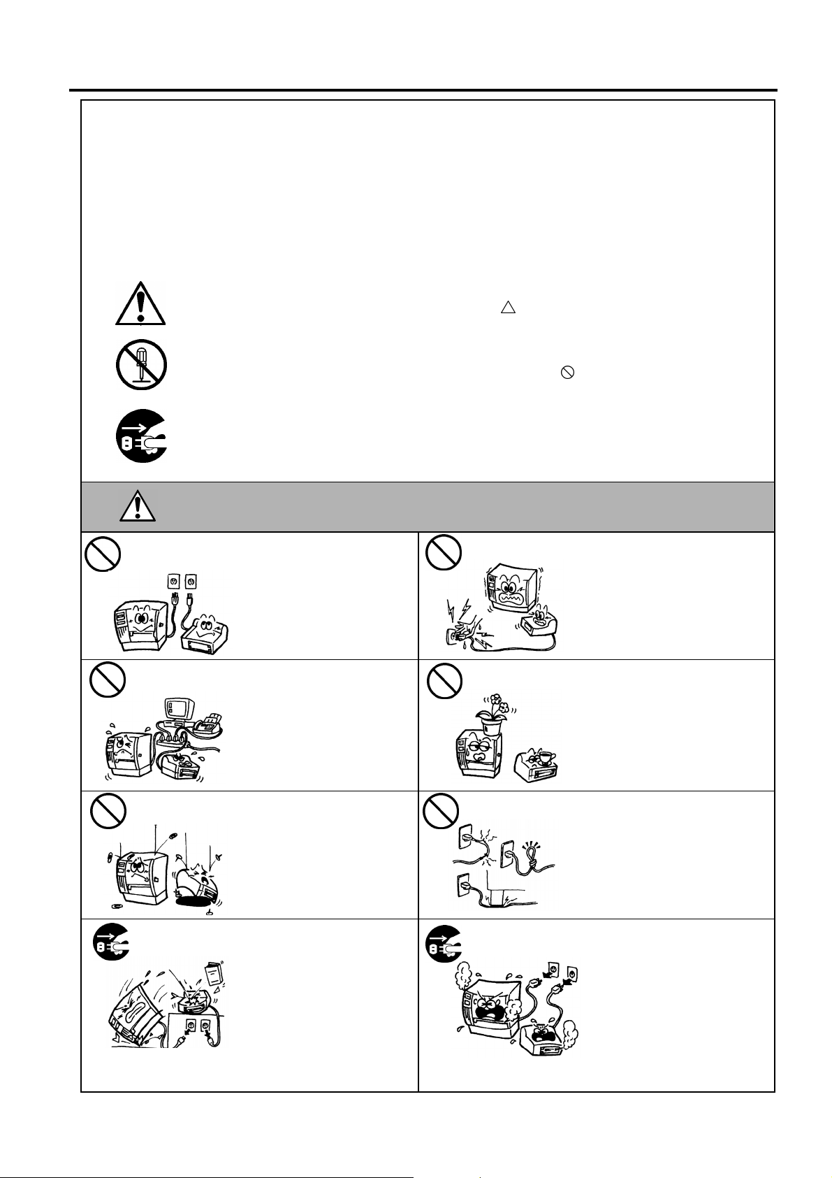
Meanings of Each Symbol
This symbol indicates warning items (including cautions).
Specific warning contents are drawn inside the
(The symbol on the left indicates a general caution.)
This symbol indicates prohibited actions (prohibited items).
Specific prohibited contents are drawn inside or near the
(The symbol on the left indicates “no disassembling”.)
This symbol indicates actions which must be performed.
Specific instructions are drawn inside or near the z symbol.
(The symbol on the left indicates “disconnect the power cord plug from the outlet”.)
symbol.
symbol.
Any other than the
specified AC voltage
is prohibited.
Prohibited
Prohibited
ARNING
Do not use voltages other than
the voltage (AC) specified on the
rating plate, as this may cause
fire or electric shock.
If the machines share the same
outlet with any other electrical
appliances that consume large
amounts of power, the voltage
will fluctuate widely each time
these appliances operate. Be sure
to provide an exclusive outlet for
the machine as this may cause
fire or electric shock.
Do not insert or drop metal,
flammable or other foreign
objects into the machines through
the ventilation slits, as this may
cause fire or electric shock.
This indicates that there is the risk of death or serious injury if the
machines are improperly handled contrary to this indication.
Prohibited
Prohibited
Prohibited
Do not plug in or unplug the power
cord plug with wet hands as this
may cause electric shock.
Do not place metal objects or
water-filled containers such as
flower vases, flower pots or mugs,
etc. on top of the machines. If
metal objects or spilled liquid enter
the machines, this may cause fire
or electric shock.
Do not scratch, damage or modify
the power cords. Also, do not
place heavy objects on, pull on, or
excessively bend the cords, as this
may cause fire or electrical shock.
Disconnect
the plug.
If the machines are dropped or
their cabinets damaged, first turn
off the power switches and
disconnect the power cord plugs
from the outlet, and then contact
your authorised TOSHIBA TEC
representative for assistance.
Continued use of the machine in
that condition may cause fire or
electric shock.
( )
i
Disconnect
the plug.
Continued use of the machines in
an abnormal condition such as
when the machines are producing
smoke or strange smells may cause
fire or electric shock. In these
cases, immediately turn off the
power switches and disconnect the
power cord plugs from the outlet.
Then, contact your authorised
TOSHIBA TEC representative for
assistance.
Page 7
Safety Summary ENGLISH VERSION
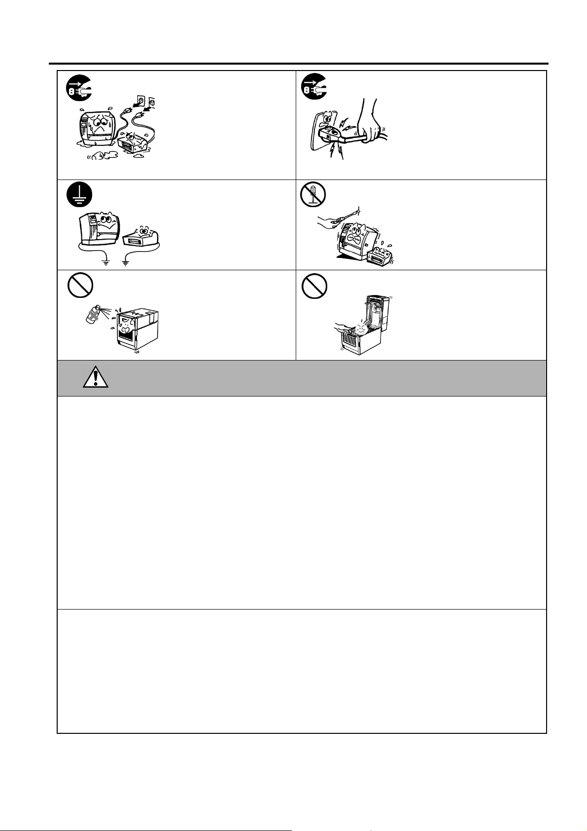
Disconnect
the plug.
Connect a
grounding wire.
Prohibited
If foreign objects (metal
fragments, water, liquids) enter
the machines, first turn off the
power switches and disconnect
the power cord plugs from the
outlet, and then contact your
authorised TOSHIBA TEC
representative for assistance.
Continued use of the machine in
that condition may cause fire or
electric shock.
Ensure that the equipment is
properly grounded. Extension
cables should also be grounded.
Fire or electric shock could
occur on improperly grounded
equipment.
Do not use a spray cleaner
containing flammable gas for
cleaning this product, as this may
cause a fire.
Disconnect
the plug.
No
disassembling.
Prohibited
When unplugging the power cords,
be sure to hold and pull on the plug
portion. Pulling on the cord portion
may cut or expose the internal wires
and cause fire or electric shock.
Do not remove covers, repair or
modify the machine by yourself.
You may be injured by high
voltage, very hot parts or sharp
edges inside the machine.
Care must be taken not to injure
yourself with the printer paper
cutter.
CAUTION
objects if the machines are improperly handled contrary to this indication.
Precautions
This indicates that there is the risk of personal Injury or damage to
The following precautions will help to ensure that this machine will continue to function correctly.
• Try to avoid locations that have the following adverse conditions:
* Temperatures out of the specification * Direct sunlight * High humidity
* Shared power source * Excessive vibration * Dust/Gas
• The cover should be cleaned by wiping with a dry cloth or a cloth slightly dampened with a mild detergent solution. NEVER
USE THINNER OR ANY OTHER VOLATILE SOLVENT on the plastic covers.
• USE ONLY TOSHIBA TEC SPECIFIED paper and ribbons.
• DO NOT STORE the paper or ribbons where they might be exposed to direct sunlight, high temperatures, high humidity, dust,
or gas.
• Ensure the printer is operated on a level surface.
• Any data stored in the memory of the printer could be lost during a printer fault.
• Try to avoid using this equipment on the same power supply as high voltage equipment or equipment likely to cause mains
interference.
• Unplug the machine whenever you are working inside it or cleaning it.
• Keep your work environment static free.
• Do not place heavy objects on top of the machines, as these items may become unbalanced and fall causing injury.
• Do not block the ventilation slits of the machines, as this will cause heat to build up inside the machines and may cause fire.
• Do not lean against the machine. It may fall on you and could cause injury.
• Unplug the machine when it is not used for a long period of time.
• Place the machine on a stable and level surface.
Request Regarding Maintenance
• Utilize our maintenance services.
After purchasing the machine, contact your authorised TOSHIBA TEC representative for assistance once a year to have the
inside of the machine cleaned. Otherwise, dust will build up inside the machines and may cause a fire or a malfunction.
Cleaning is particularly effective before humid rainy seasons.
• Our preventive maintenance service performs the periodic checks and other work required to maintain the quality and
performance of the machines, preventing accidents beforehand.
For details, please consult your authorised TOSHIBA TEC representative for assistance.
• Using insecticides and other chemicals
Do not expose the machines to insecticides or other volatile solvents. This will cause the cabinet or other parts to deteriorate or
cause the paint to peel.
( )
ii
Page 8

ENGLISH VERSION EO1-33089
TABLE OF CONTENTS
Page
1. PRODUCT OVERVIEW......................................................................................................... E1- 1
1.1 Introduction................................................................................................................... E1- 1
1.2 Features ....................................................................................................................... E1- 1
1.3 Unpacking..................................................................................................................... E1- 1
1.4 Accessories ................................................................................................................. E1- 2
1.5 Appearance .................................................................................................................. E1- 3
1.5.1 Dimensions..............................................................................................................E1- 3
1.5.2 Front View ...............................................................................................................E1- 3
1.5.3 Rear View................................................................................................................E1- 3
1.5.4 Operation Panel ......................................................................................................E1- 4
1.5.5 Interior .....................................................................................................................E1- 4
1.6 Options ......................................................................................................................... E1- 5
2. PRINTER SETUP .................................................................................................................. E2- 1
2.1 Installation .................................................................................................................... E2- 2
2.2 Connecting the Power Cord ......................................................................................... E2- 3
2.3 Loading Supplies .......................................................................................................... E2- 4
2.3.1 Loading the Media...................................................................................................E2- 5
2.3.2 Loading the Ribbon ................................................................................................E2-10
2.4 Connecting the Cables to Your Printer ........................................................................ E2-12
2.5 Turning the Printer ON/OFF ........................................................................................ E2-13
2.5.1 Turning ON the Printer ...........................................................................................E2-13
2.5.2 Turning OFF the Printer..........................................................................................E2-13
2.6 Printer Setting........................................................................................................................... E2-14
2.6.1 User System Mode .................................................................................................E2-15
2.6.2 Parameter Setting ..................................................................................................E2-16
2.6.3 Enabling LAN/WLAN ..............................................................................................E2-24
2.6.4 Basic Program Setting............................................................................................E2-24
2.6.5 Enabling Z-Mode ....................................................................................................E2-25
2.6.6 Automatic Calibration .............................................................................................E2-26
2.6.7 Dump Mode Setting................................................................................................E2-27
2.6.8 Logging...................................................................................................................E2-29
2.6.9 System Mode .........................................................................................................E2-30
2.6.10 Interface Setting .....................................................................................................E2-31
2.6.11 Real Time Clock (RTC) ..........................................................................................E2-38
2.6.12 Copying Data to/from USB Memory .......................................................................E2-39
2.7 Installing the Printer Drivers ........................................................................................ E2-40
2.7.1 Introduction...............................................................................................................E2-40
2.7.2 General Description................................................................................................E2-40
2.7.3 Installing the Printer Driver .....................................................................................E2-40
2.7.4 Preparation for installation......................................................................................E2-41
2.7.5 Installation under Windows2000/XP/Server2003 ...................................................E2-43
2.7.6 Installation under WindowsVista/Server2008/7/Server2008R2 ..............................E2-48
2.7.7 Installation under Windows2000 (USB with Plug & Play enabled) .........................E2-51
2.7.8 Installation under WindowsXP/Server2003 (USB with Plug & Play enabled) .........E2-53
2.7.9 Installation under Windows Vista/Server2008/7/Server2008R2
(USB with Plug & Play enabled) .............................................................................E2-54
2.7.10 Uninstallation the Printer Driver..............................................................................E2-55
2.8 Print Test ..................................................................................................................... E2-58
Page 9

ENGLISH VERSION EO1-33089
y
2.9 Position and Print Tone Fine Adjustment ................................................................... E2-60
2.9.1 Fine Adjustment .....................................................................................................E2-60
2.10 Threshold Setting ........................................................................................................ E2-67
2.11 Sensor Setting ............................................................................................................. E2-69
3. ON LINE MODE..................................................................................................................... E3- 1
3.1 Key Functions............................................................................................................... E3- 1
3.2 LCD .............................................................................................................................. E3- 2
3.2 Operation Example....................................................................................................... E3- 3
4. MAINTENANCE .................................................................................................................... E4- 1
4.1 Cleaning ....................................................................................................................... E4- 1
4.1.1 Print Head/Platen/Sensors ......................................................................................E4- 1
4.1.2 Covers and Panels ..................................................................................................E4- 2
4.1.3 Optional Cutter Module............................................................................................E4- 3
5. TROUBLESHOOTING .......................................................................................................... E5- 1
5.1 Error Messages ............................................................................................................ E5- 1
5.2 Possible Problems........................................................................................................ E5- 4
5.3 Removing Jammed Media ............................................................................................ E5- 5
6. PRINTER SPECIFICATIONS................................................................................................ E6- 1
7. SUPPLY SPECIFICATIONS ................................................................................................. E7- 1
7.1 Media............................................................................................................................ E7- 1
7.1.1 Media Type..............................................................................................................E7- 1
7.1.2 Detection Area of the Transmissive Sensor ............................................................E7- 3
7.1.3 Detection Area of the Reflective Sensor..................................................................E7- 4
7.1.4 Effective Print Area..................................................................................................E7- 4
7.1.5 RFID Tags ...............................................................................................................E7- 5
7.2 Ribbon .......................................................................................................................... E7- 7
7.3 Recommended Media and Ribbon Types .................................................................... E7- 7
7.4 Care/Handling of Media and Ribbon ............................................................................ E7- 8
APPENDIX 1 MESSAGES AND LEDS......................................................................................EA1-1
APPENDIX 2 INTERFACE ......................................................................................................... EA2-1
APPENDIX 3 PRINT SAMPLES ................................................................................................EA3-1
APPENDIX 4 GLOSSARIES ......................................................................................................EA4-1
WARNING!
This is a Class A product. In a domestic environment this product may cause radio interference in
which case the user ma
CAUTION!
1. This manual may not be copied in whole or in part without prior written permission of TOSHIBA TEC.
2. The contents of this manual may be changed without notification.
3. Please refer to your local Authorised Service representative with regard to any queries you may have in
this manual.
be required to take adequate measures.
Page 10

1. PRODUCT OVERVIEW ENGLISH VERSION EO1-33089
1. PRODUCT OVERVIEW
1.1 Introduction
1.2 Features
1.3 Unpacking
1. Check for damage or
scratches on the printer.
However, please note that
TOSHIBA TEC shall have no
liability for any damage of
any kind sustained during
transportation of the product.
2. Keep the cartons and pads
for future transportation of
the printer.
NOTES:
Thank you for choosing the TOSHIBA B-EX4T1 series bar code printer.
This Owner’s Manual contains from general set-up through how to
confirm the printer operation using a test print, and should be read
carefully to help gain maximum performance and life from your printer.
For most queries please refer to this manual and keep it safe for future
reference. Please contact your TOSHIBA TEC representative for further
information concerning this manual.
This printer has the following features:
• The print head block can be opened providing smooth loading of
media and ribbon.
• Various kinds of media can be used as the media sensors can be
moved from the centre to the left edge of the media.
• Web functions such as remote maintenance and other advanced
network features are available.
• Superior hardware, including the specially developed 8 dots/mm (203
dots/inch) or 12 dots/mm (305 dots/inch) thermal print head which
will allow very clear print at a printing speed of 3 inches/sec., 6
inches/sec., 10 inches/sec., 12 inches/sec. or 14 inches/sec. with 8
dots/mm thermal head or 3 inches/sec., 5 inches/sec., 8 inches/sec., 10
inches/sec., 12 inches/sec. or 14 inches/sec. with 12 dots/mm thermal
head.
• Besides the optional Cutter Module, there is also an optional Peel off
Module, Ribbon Saving Module, RS-232C I/F card, Centronics I/F
card, Expansion I/O Card, Wireless LAN I/F card, the RTC/USB host
I/F card, RFID module, and Narrow width platen kit.
Unpack the printer as per the Unpacking Instructions supplied with the
printer.
1.1 Introduction
E1- 1
Page 11
1. PRODUCT OVERVIEW ENGLISH VERSION EO1-33089
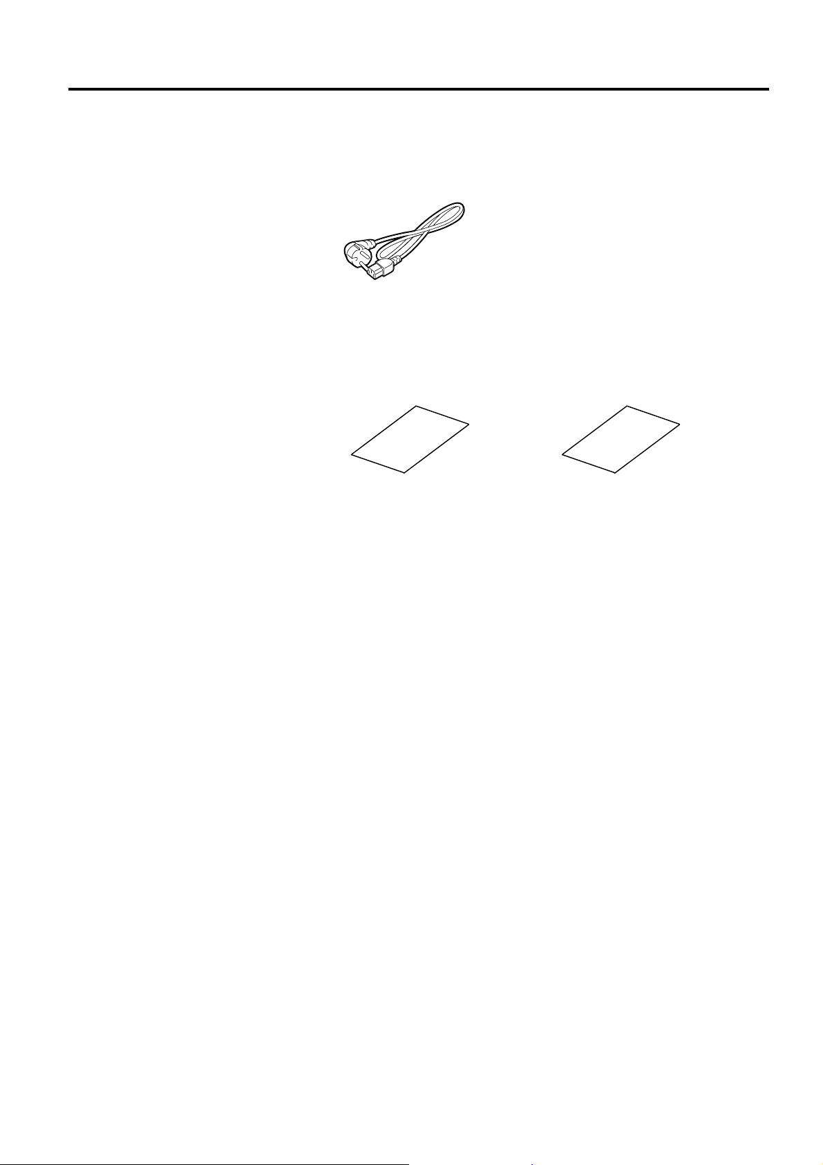
1.4 Accessories
1.4 Accessories
When unpacking the printer, please make sure all the following
accessories are supplied with the printer.
Power cord
Safety precautions Quick installation manual
E1- 2
Page 12
1. PRODUCT OVERVIEW ENGLISH VERSION EO1-33089
y
A
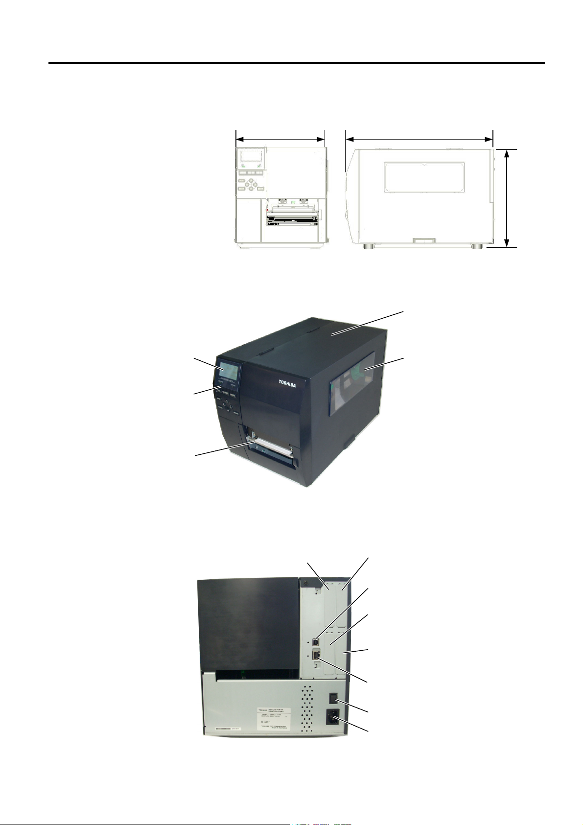
1.5 Appearance
1.5.1 Dimensions
1.5.2 Front View
LCD Message Displa
Operation Panel
Media Outlet
1.5 Appearance
The names of the parts or units introduced in this section are used in the
following chapters.
278 (10.9) 460 (18.1)
310
(12.2)
Dimensions in mm (inches)
Top Cover
Supply Window
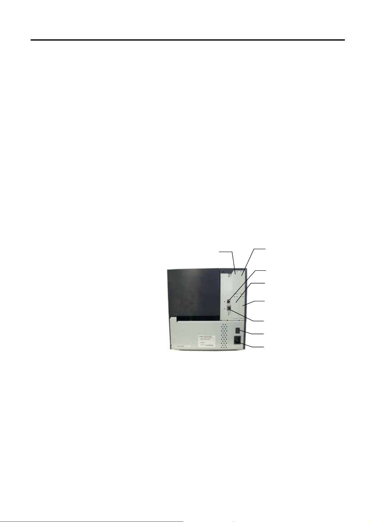
1.5.3 Rear View
Reserved for Parallel Interface
Reserved for Serial or
WLAN Interface
E1- 3
USB Interface
Reserved for USB Host
Interface
Reserved for Expansion I/O
interface
LAN Interface
Power Switch
C Power Inlet
Page 13
1. PRODUCT OVERVIEW ENGLISH VERSION EO1-33089
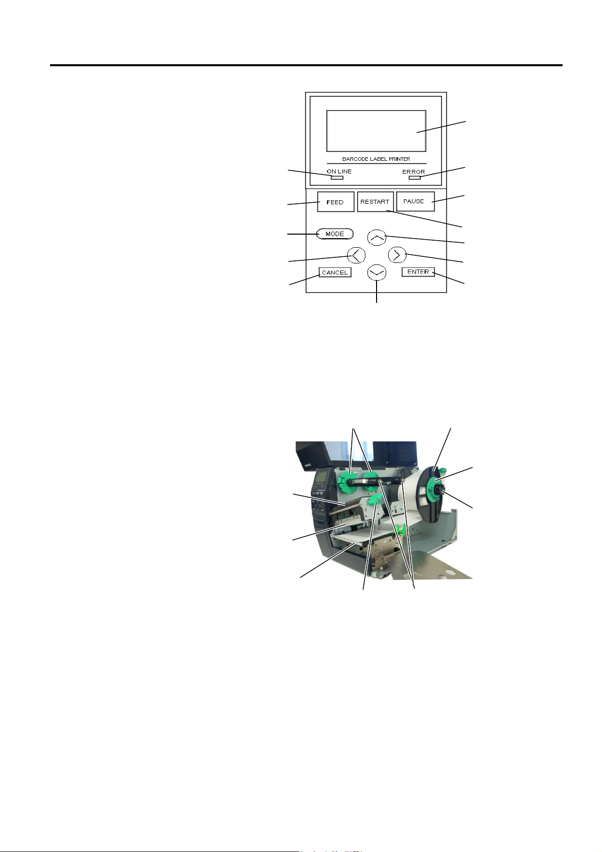
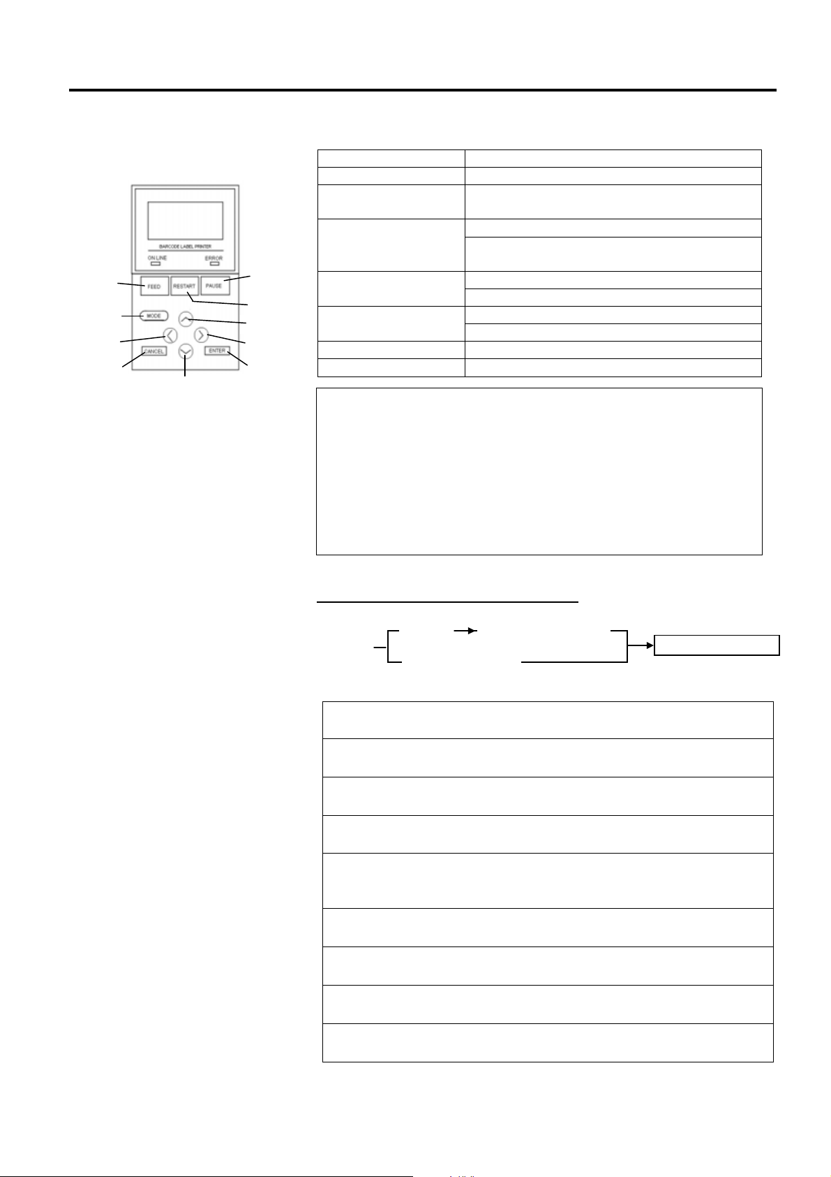
1.5.4 Operation Panel
1.5.5 Interior
1.5 Appearance
ONLINE LED
FEED
MODE
LEFT
CANCEL
DOWN
Please see Section 3 for further information about the Operation Panel.
LCD
ERROR LED
PAUSE
RESTART
UP
RIGHT
ENTER
Ribbon Stopper
Print Head Block
Print Head
Platen
Head Lever
Supply Holder
Locking Ring
Supply Shaft
Ribbon Shaft
E1- 4
Page 14

1. PRODUCT OVERVIEW ENGLISH VERSION EO1-33089
N
1.6 Options
Option Name Type Description
Disc cutter module B-EX204-QM-R Disc cutter
Rotary cutter module B-EX204-R-QM-R Rotary cutter
Strip module B-EX904-H-QM-R This allows use of on-demand (peel-off) operation or
Ribbon saving module B-EX904-R-QM-R This module moves the print head up and down by
Narrow width platen B-EX904-PK-QM-R This platen kit is for using narrow and thin paper.
RFID module mount
kit
RFID module B-EX700-RFID-U2-EU-R
203-dpi print head B-EX704-TPHE2-QM-R This print head enables a conversion of a 305dpi
305-dpi print head B-EX704-TPHE3-QM-R This print head enables a conversion of a 203dpi
RTC & USB host
interface card
Expansion I/O interface
card
Parallel interface card B-EX700-CEN-QM-R Installing this card provides a Centronics interface
Serial interface card B-EX700-RS-QM-R Installing this card provides an RS-232C interface
Wireless LAN interface
card
B-EX700-RFID-H1-QM-R This kit is to mount Tagsys HF RFID module and
B-EX700-RFID-U2-US-R
B-EX700-RFID-U2-CN-R
B-EX700-RTC-QM-R This card holds the current time: year, month, day,
B-EX700-IO-QM-R Installing this card in the printer allows connection
B-EX700-WLAN-QM-R Installing this card allows a communication by
Each time media is cut, the media feed is stopped.
On-the-fly (non-stop) cut operation is enabled.
to take-up labels and backing paper together when
using the rewind guide plate. To purchase the strip
module, please inquire at your local distributor.
using a solenoid to minimize ribbon usage as far as
possible.
antenna.
Installing this module enables read and write of
UHF RFID tags.
EU for Europe
US for USA/Canada
CN for China
print head of the B-EX4T1-TS12 model into 203dpi
print head.
print head of the B-EX4T1-GS12 model into 305dpi
print head.
hour, minute, second and provides a USB host
interface.
to an external device with the exclusive interface.
port.
port.
wireless LAN.
1.6 Options
OTE:
To purchase the optional kits, please contact the nearest authorised TOSHIBA TEC representative or
TOSHIBA TEC Head Quarters.
E1- 5
Page 15
2. PRINTER SETUP ENGLISH VERSION EO1-33089
p
g
j
2. PRINTER SETUP
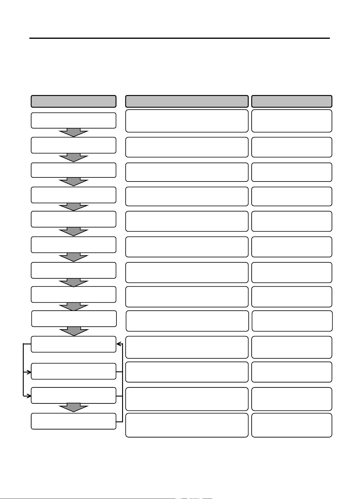
2. PRINTER SETUP
This section outlines the procedures to setup your printer prior to its operation. The section includes precautions,
loading media and ribbon, connecting cables, setting the operating environment of the printer, and performing an
online print test.
Installation
Connecting the power cord
Loading the media
Media sensor position
nment
ali
After referring to the Safety Precautions in this
manual, install the printer on a safe and stable
location.
Connect a power cord to the power inlet of the
rinter, then, to an AC outlet.
Load a label stock or tag stock.
Adjust the position of feed gap sensor or black
mark sensor according to the media to be used.
2.1 Installation
2.2 Connecting the Power
2.3 Loading the Media
2.3.1 Loading the Media
Reference Procedure Setup Flow
Cord
Loading the ribbon
Connecting to a host computer
Turning the power ON
Printer setting
Installing the printer driver
Print test
Position and Print Tone Fine
ustment
ad
In case of thermal transfer printing, load the
ribbon.
Connect the printer to a host computer or a
network.
Turn on the printer power.
Set the printer parameters in the system mode.
If necessary, install the printer driver in your
host computer.
Make a print test in your operating
environment and check the print result.
If necessary, fine adjust the print start position,
cut/strip position, print tone, etc.
2.3.2 Loading the Ribbon
2.4 Connecting the Cables to
Your Printer
2.5 Turning the Printer
ON/OFF
2.6 Printer Setting
2.7 Installing the Printer
Drivers
2.8 Print Test
2.9 Position and Print Tone
Fine Adjustment
Automatic threshold setting
Manual threshold setting
If the print start position cannot be detected
properly when pre-printed label is used, set the
threshold automatically.
If the print start position cannot be detected
properly even an automatic threshold setting is
performed, manually set the threshold.
E2- 1
2.10 Threshold Setting
2.10 Threshold Setting
Page 16

2. PRINTER SETUP ENGLISH VERSION EO1-33089
2.1 Installation
2.1 Installation
To insure the best operating environment, and to assure the safety of the
operator and the equipment, please observe the following precautions.
• Operate the printer on a stable, level, operating surface in a location
free from excessive humidity, high temperature, dust, vibration or
direct sunlight.
• Keep your work environment static free. Static discharge can cause
damage to delicate internal components.
• Make sure that the printer is connected to a clean source of AC
Power and that no other high voltage devices that may cause line
noise interference are connected to the same mains.
• Assure that the printer is connected to the AC mains with a threeprong power cable that has the proper ground (earth) connection.
• Do not operate the printer with the cover open. Be careful not to
allow fingers or articles of clothing to get caught into any of the
moving parts of the printer especially the optional cutter mechanism.
• Make sure to turn off the printer power and to remove the power cord
from the printer whenever working on the inside of the printer such
as changing the ribbon or loading the media, or when cleaning the
printer.
• For best results, and longer printer life, use only TOSHIBA TEC
recommended media and ribbons.
• Store the media and ribbons in accordance with their specifications.
• This printer mechanism contains high voltage components; therefore
you should never remove any of the covers of the machine as you
may receive an electrical shock. Additionally, the printer contains
many delicate components that may be damaged if accessed by
unauthorised personnel.
• Clean the outside of the printer with a clean dry cloth or a clean cloth
slightly dampened with a mild detergent solution.
• Use caution when cleaning the thermal print head as it may become
very hot while printing. Wait until it has had time to cool before
cleaning. Use only the TOSHIBA TEC recommended print head
cleaner to clean the print head.
• Do not turn off the printer power or remove the power plug while the
printer is printing or while the ON LINE lamp is blinking.
E2- 2
Page 17
2. PRINTER SETUP ENGLISH VERSION EO1-33089
r
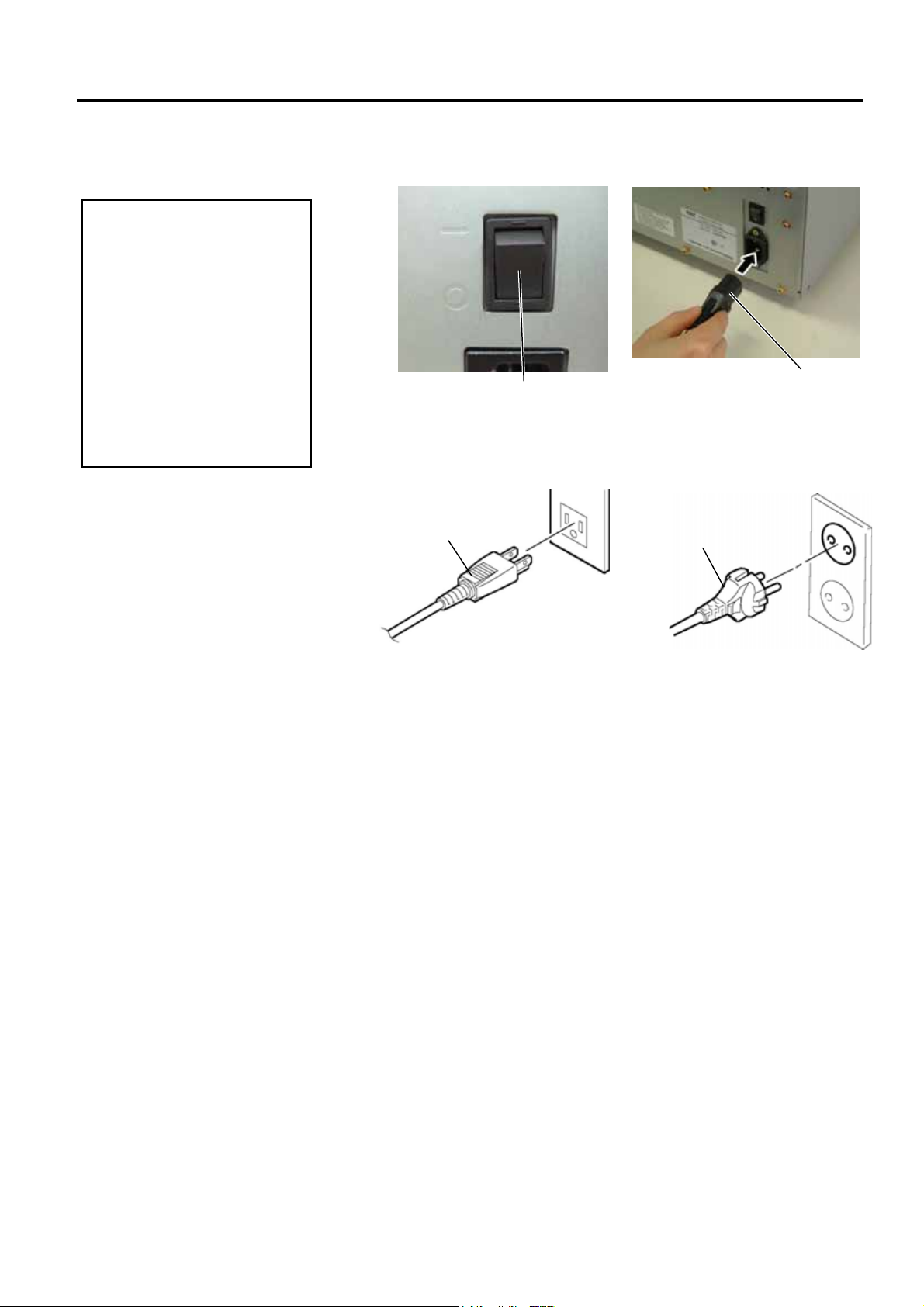
2.2 Connecting the Power Cord
1. Make sure that the printe
2. Connect the Power Cord
CAUTION!
Power Switch is turned to
the OFF position ({)
before connecting the
Power Cord to prevent
possible electric shock or
damage to the printer.
to a supply outlet with a
properly grounded
(earthed) connection.
2.2 Connecting the Power Cord
1. Make sure that the printer Power Switch is in the OFF ({) position.
Connect the Power Cord to the printer as shown in the figure below.
2. Plug the other end of the Power Cord into a grounded outlet as shown
in the figure below.
[Example of US Type] [Example of EU Type]
Power Cord
Power Switch
Power Cord
Power Cord
E2- 3
Page 18
2. PRINTER SETUP ENGLISH VERSION EO1-33089
2.3 Loading Supplies
2.3 Loading Supplies
1. Do not touch any moving parts. To reduce the risk of fingers, jewellery, clothing, etc., being
drawn into the moving parts, be sure to load the media once the printer has stopped moving
completely.
2. The Print Head becomes hot immediately after printing. Allow it to cool before loading the media.
3. To avoid injury, be careful not to trap your fingers while opening or closing the cover.
WARNING!
CAUTION!
1. Be careful not to touch the Print Head Element when raising the Print Head Block. Failure to do
this may cause missing dots by static electricity or other print quality problems.
2. When loading or replacing the media or a ribbon, be careful not to damage the print head with a
hard object like a watch or a ring.
Since the print head element can be easily damaged by shock, please treat it carefully by not
hitting a hard object against it.
Care must be taken not to allow
the metal or glass part of a watch
to touch the print head edge.
Care must be taken not to allow
a metal object like a ring to touch
the print head edge.
E2- 4
Page 19
2. PRINTER SETUP ENGLISH VERSION EO1-33089
t
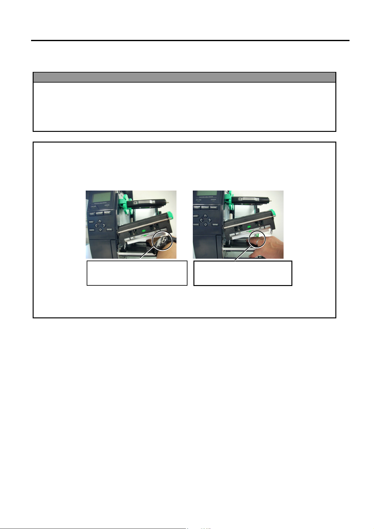
2.3.1 Loading the Media
1. When the Head Lever is
turned to
Print Head is raised.
2. To enable printing the Head
Lever must be set to the
LABEL / TAG position.
(This ensures that the Print
Head is closed.)
There are two head pressure
levels in the
position. Set the Head Lever
depending on the media type:
Position LABEL: Labels
Position TAG : Tags
However, proper position
may differ depending on
media. For details, refer to
your TOSHIBA TEC
authorised service
representative.
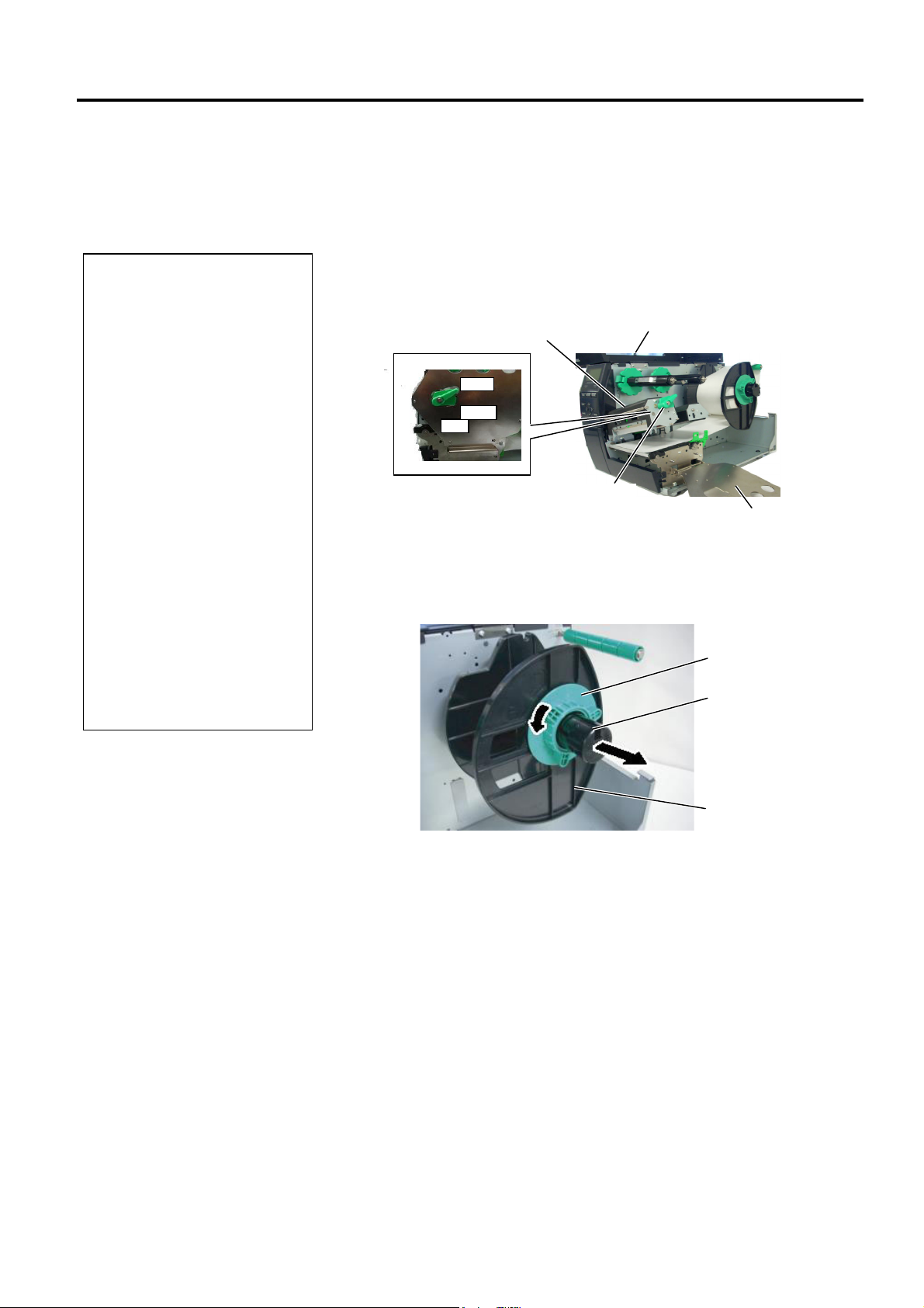
3. Do not turn the Locking Ring
counter-clockwise too far or i
may come off the Supply
Holder.
NOTES:
FREE position, the
LABEL / TAG
2.3 Loading Supplies
The following procedure shows the steps to properly load the media into
the printer so that it feeds straight and true through the printer.
The printer prints both labels and tags.
1. Turn off the power and open the Top Cover.
2. Turn the Head Lever to FREE position, then release the Ribbon Shaft
Holder Plate.
3. Open the Print Head Block.
Print Head Block
Top Cover
FREE
LABEL
TAG
Head
Lever
Ribbon Shaft Holder Plate
4. Turn the Locking Ring counterclockwise and remove the Supply
Holder from the Supply Shaft.
Locking Ring
Supply Shaft
Supply Holder
5. Put the media on the Supply Shaft.
6. Pass the media around the Guide Shaft, then pull the media towards
the front of the printer.
E2- 5
Page 20
2. PRINTER SETUP ENGLISH VERSION EO1-33089
D
g
R
h
2.3.1 Loading the Media
(Cont.)
o not over-tighten the Lockin
ing of the Supply Holder.
NOTE:
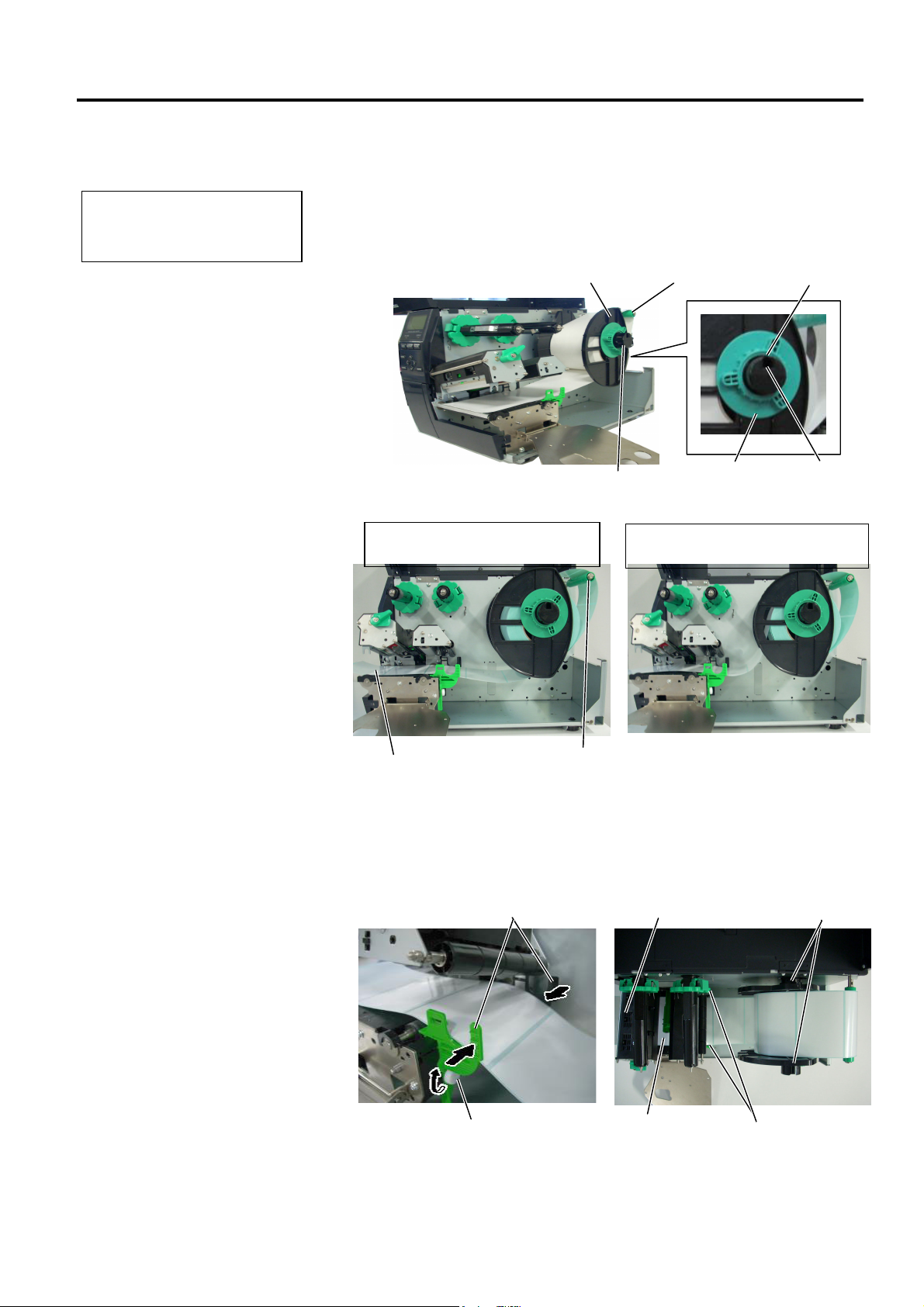
2.3 Loading Supplies
7. Align the projection of the Supply Holder with the groove of the
Supply Shaft, and push the Supply Holder against the media until the
media is held firmly in place. This will centre the media
automatically.
Then turn the Locking Ring clockwise to secure the Supply Holder.
Supply Holder
Guide Shaft
Projection
Supply Shaft
Locking Ring
Groove
In the case of a label rolled wit
the print side facing inside.
In the case of a label rolled with
the print side facing outside.
Media
Guide Shaft
8. Place the media between the Media Guides, adjust the Media Guides
to the media width, and tighten the Locking Screw.
9. Check that the media path through the printer is straight. The media
should be centred under the Print Head.
Media Guide
Print Head
Supply Holder
Locking Screw
Media
Media Guide
E2- 6
Page 21
2. PRINTER SETUP ENGLISH VERSION EO1-33089
B
j
2.3.1 Loading the Media
(Cont.)
NOTE:
e sure to set the black mark
sensor to detect the centre of the
black mark, otherwise a paper
am or no paper error may occur.
2.3 Loading Supplies
10. Lower the Print Head Block until it stops.
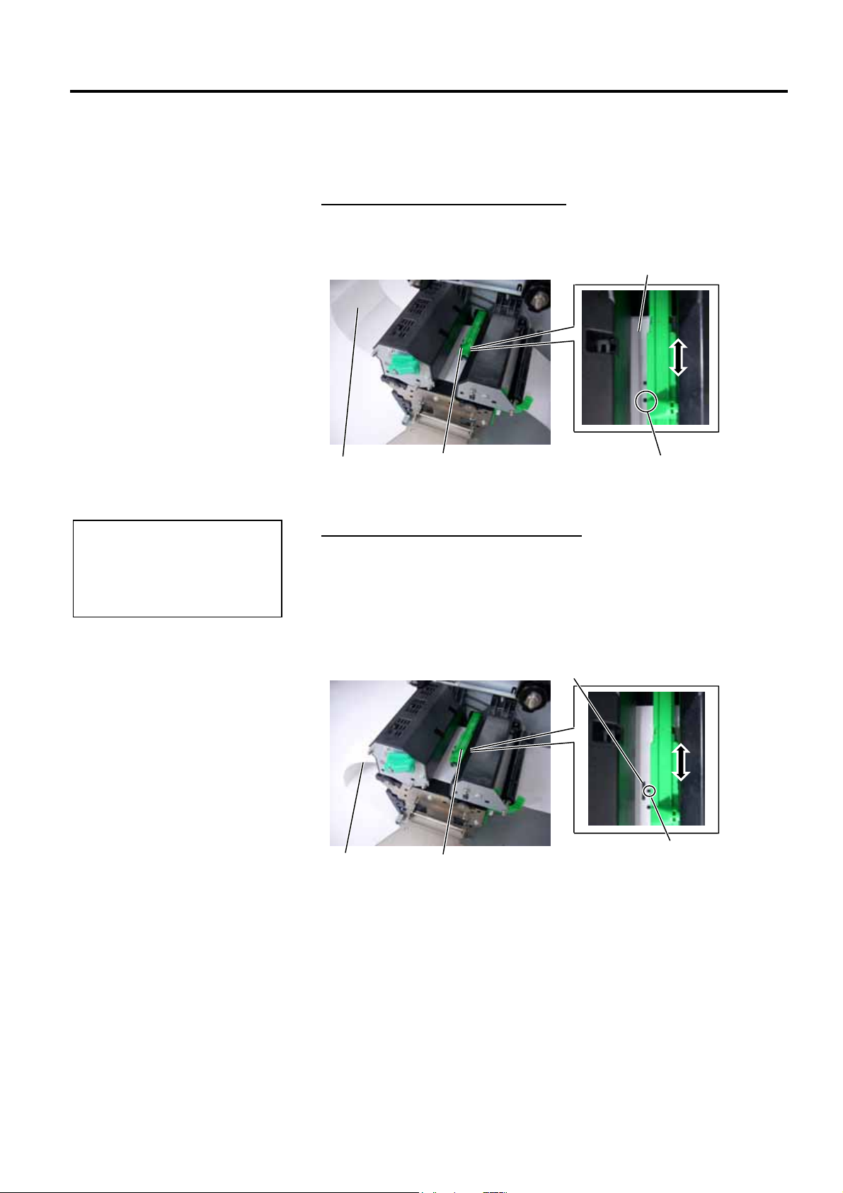
11. After loading the media, it may be necessary to set the Media
Sensors used to detect the print start position for label or tag printing.
Setting the Feed Gap Sensor position
(1) Manually move the Media Sensor so that the Feed Gap Sensor is
positioned at the centre of the labels. (z indicates the position of the
Feed Gap Sensor).
Gap
Label Media Sensor
Feed Gap Sensor (z)
Setting the Black Mark Sensor position
(1) Pull about 500 mm of media out of the front of the printer, turn the
media back on itself and feed it under the Print Head past the sensor
so that the black mark can be seen from above.
(2) Manually move the Media Sensor so that the Black Mark Sensor is
in line with the centre of the black mark on the media. ( indicates
the position of the Black Mark Sensor).
Black Mark
Media
Media Sensor
E2- 7
Black Mark Sensor ()
Page 22
2. PRINTER SETUP ENGLISH VERSION EO1-33089
f
2.3.1 Loading the Media
(Cont.)
NOTES:
1. Be sure to set the Selection
Switch to STANDARD/
PEEL OFF position.
2. The backing paper is easier
to feed back to the Take-Up
Spool if the Front Plate is
removed.
3. Fit the Take-Up Clip so that
the longer side of the clip is
itted into the shallow groove
in the Take-Up Spool.
4. The backing paper can be
wound directly onto the
Take-up Spool or a paper
core.
2.3 Loading Supplies
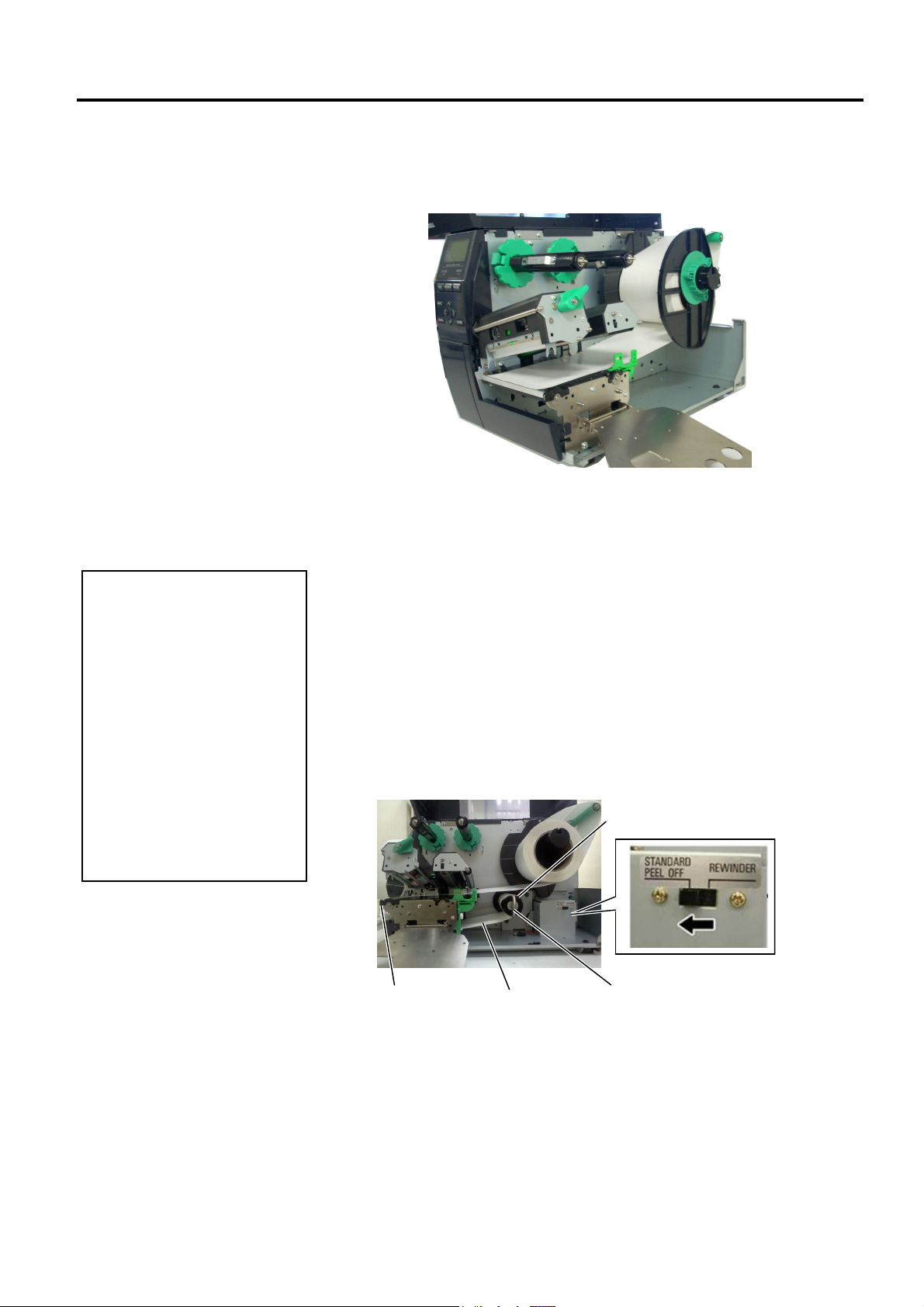
12. Batch mode
In the batch mode, the media is continuously printed and fed until
the number of labels/tags specified in the issue command have been
printed.
13. Loading with peel off module
When the optional Strip Module is fitted, the backing paper is
automatically removed from the label at the Strip Plate as each label
is printed.
(1) Remove enough labels from the leading edge of the media to leave
500mm of backing paper free.
(2) Insert the backing paper under the Strip Plate.
(3) Wind the backing paper onto the Take-up Spool and fix it in position
with the Take-up Clip. (Wind the paper counterclockwise around
the spool as this is the direction it rotates.)
(4) Rotate the Take-up Spool counter-clockwise a few times to remove
any slack in the backing paper.
(5) Set the Selection Switch mounted on the Rewinder Assembly to
STANDARD/PEEL OFF position.
Take-up Spool
Backing Paper Strip Plate
Take-up Clip
E2- 8
Page 23
2. PRINTER SETUP ENGLISH VERSION EO1-33089
y
F
p
2.3.1 Loading the Media
(Cont.)
The cutter is sharp, so care
must be taken not to injure
yourself when handling the
cutter.
1. Be sure to cut the backing
paper of the label. Cutting
labels will cause the glue to
stick to the cutter which
may affect the cutter qualit
and shorten the cutter life.
2. Use of tag paper when the
thickness exceeds the
specified value may affect
the cutter life.
When using the Rotary Cutter, be
sure to install the Ribbon Saving
Module (B-EX904-R-QM-R).
ailure to do this may cause a
aper jam or ribbon error.
WARNING!
CAUTION!
NOTE:
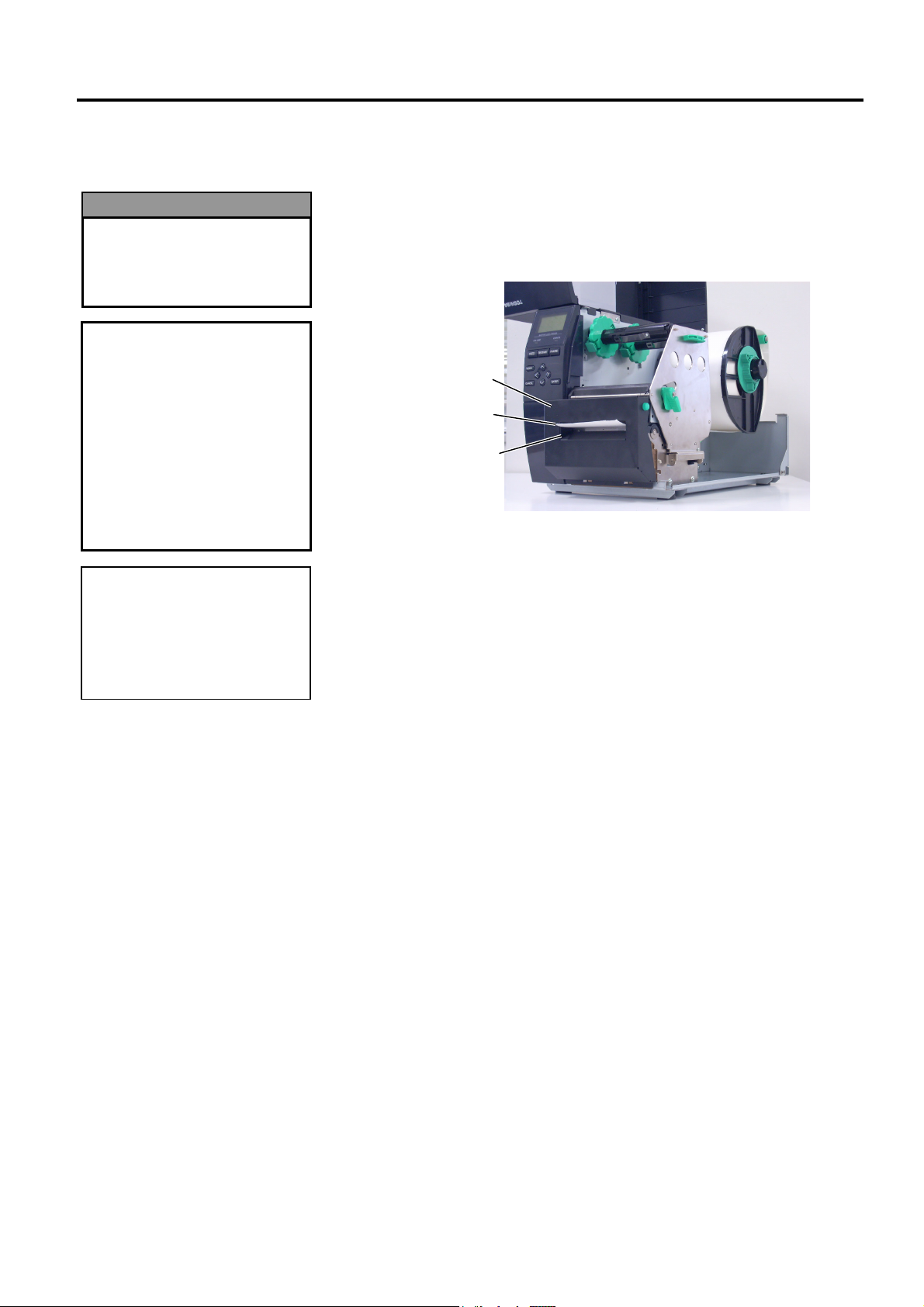
14. Loading with cutter
When the optional Cutter Module is fitted, the media is
automatically cut. A disc cutter and a rotary cutter are available as
an option, but they are used in the same way.
Insert the leading edge of the media into the cutter until it comes out
the Media Outlet of the Cutter Module.
Cutter Module
Media Outlet
Media
2.3 Loading Supplies
E2- 9
Page 24
2. PRINTER SETUP ENGLISH VERSION EO1-33089
2.3.2 Loading the Ribbon
NOTES:
1. When attaching the ribbon
stoppers, make sure that the
pinchers face into the printer
2. Be sure to remove any slack in
the ribbon when printing.
Printing with a wrinkled
ribbon will lower the print
quality.
3. The Ribbon Sensor is mounted
on the rear of the Print Head
Block to detect a ribbon end.
When a ribbon end is
detected, “NO RIBBON”
message will appear on the
display and the ERROR LED
will illuminate.
2.3 Loading Supplies
There are two types of media available for printing on: these are thermal
transfer media and direct thermal media (a chemically treated surface).
DO NOT LOAD a ribbon when using a direct thermal media.
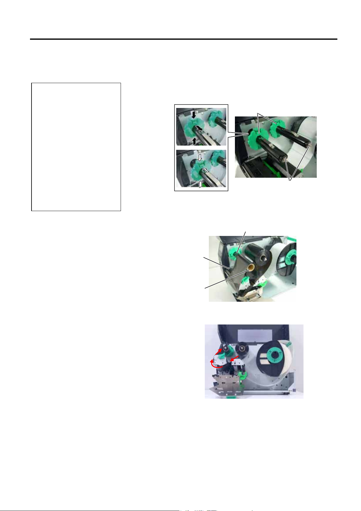
1. Grasp the tabs on the top and bottom of the Ribbon Stoppers and
move the Ribbon Stoppers back to the end of the Ribbon Shaft.
Ribbon Stopper
Ribbon Shaft
2. Leaving plenty of slack between the ribbon spools, place the ribbon
onto the Ribbon Shafts as shown below.
Ribbon Shaft
Print Head Block
Ribbon Take-up Roll
Ribbon path
E2-10
Page 25
2. PRINTER SETUP ENGLISH VERSION EO1-33089
2.3.2 Loading the Ribbon
(Cont.)
2.3 Loading Supplies
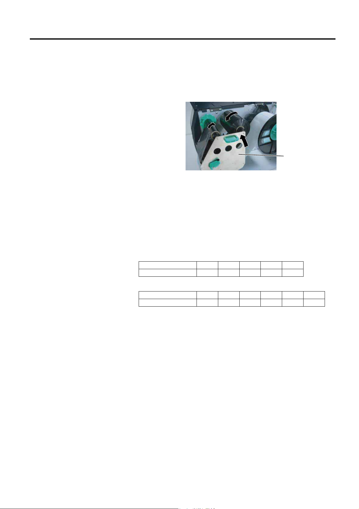
3. Slide the Ribbon Stoppers along the Ribbon Shafts to a position where
the ribbon is centred when fitted.
4. Lower the Print Head Block and set the Ribbon Shaft Holder Plate
aligning its holes with the Ribbon Shafts.
5. Take up any slack in the ribbon. Wind the leading tape onto the
ribbon take-up roll until the ink ribbon can be seen from the front of
the printer.
Ribbon Shaft
Holder Plate
6. Turn the Head Lever to Lock position to close the Print Head.
7. Close the Top Cover.
Auto Ribbon Saving Mode
When the optional Ribbon Saving Module (B-EX904-R-QM-R) is
installed, it is possible to reduce ribbon loss by stopping the ribbon feed
for non-print areas. To activate the ribbon save, at least the following
non-print area is required:
203 dpi mode
Print speed 3 ips 6 ips 10 ips 12 ips 14 ips
Min. non-print area 20 20 35 60 75
(mm)
305 dpi model
Print speed 3 ips 5 ips 8 ips 10 ips 12 ips 14 ips
Min. non-print area 20 20 25 35 60 75
(mm)
E2-11
Page 26
2. PRINTER SETUP ENGLISH VERSION EO1-33089
r
A
2.4 Connecting the
Cables to Your
Printer
2.4 Connecting the Cables to Your Printer
The following paragraphs outline how to connect the cables from the
printer to your host computer, and will also show how to make cable
connections to other devices. Depending on the application software
you use to print labels, there are 5 possibilities for connecting the
printer to your host computer. These are:
• An Ethernet connection using the printer’s standard LAN
connector.
• A USB cable connection between the printer’s standard USB
connector and your host computer’s USB port. (Conforming to
USB 2.0)
• A serial cable connection between the printer’s optional RS-232
serial connector and one of your host computer’s COM ports.
• A parallel cable connection between the printer’s optional parallel
connector and your host computer’s parallel port (LPT).
• Wireless LAN using an optional Wireless LAN board.
For details, refer to APPENDIX 2.
Reserved fo
Parallel Interface
Reserved for Serial or
WLAN Interface
USB Interface
Reserved for USB Host
interface
Reserved for
Expansion I/O Interface
LAN Interface
Power Switch
C Power Inlet
E2-12
Page 27
2. PRINTER SETUP ENGLISH VERSION EO1-33089
I
L
E
2.5 Turning the Printer ON/OFF
2.5.1 Turning ON the Printer
Use the power switch to turn
the printer On/Off. Plugging
or unplugging the Power Cord
to turn the printer On/Off may
cause fire, an electric shock,
or damage to the printer.
f a message other than ON
INE appears on the display or
the ERROR LED lamp is
illuminated, refer to Section 5.1,
rror Messages.
2.5.2 Turning OFF the Printer
1. Do not turn off the printer
2. Do not turn off the printer
CAUTION!
CAUTION!
power while the media is
being printed, as this may
cause a paper jam or
damage to the printer.
power while the ON LINE
lamp is blinking as this
may cause damage to
your computer.
NOTE:
2.5 Turning the Printer ON/OFF
When the printer is connected to your host computer it is good practice to
turn the printer ON before turning on your host computer and turn OFF
your host computer before turning off the printer.
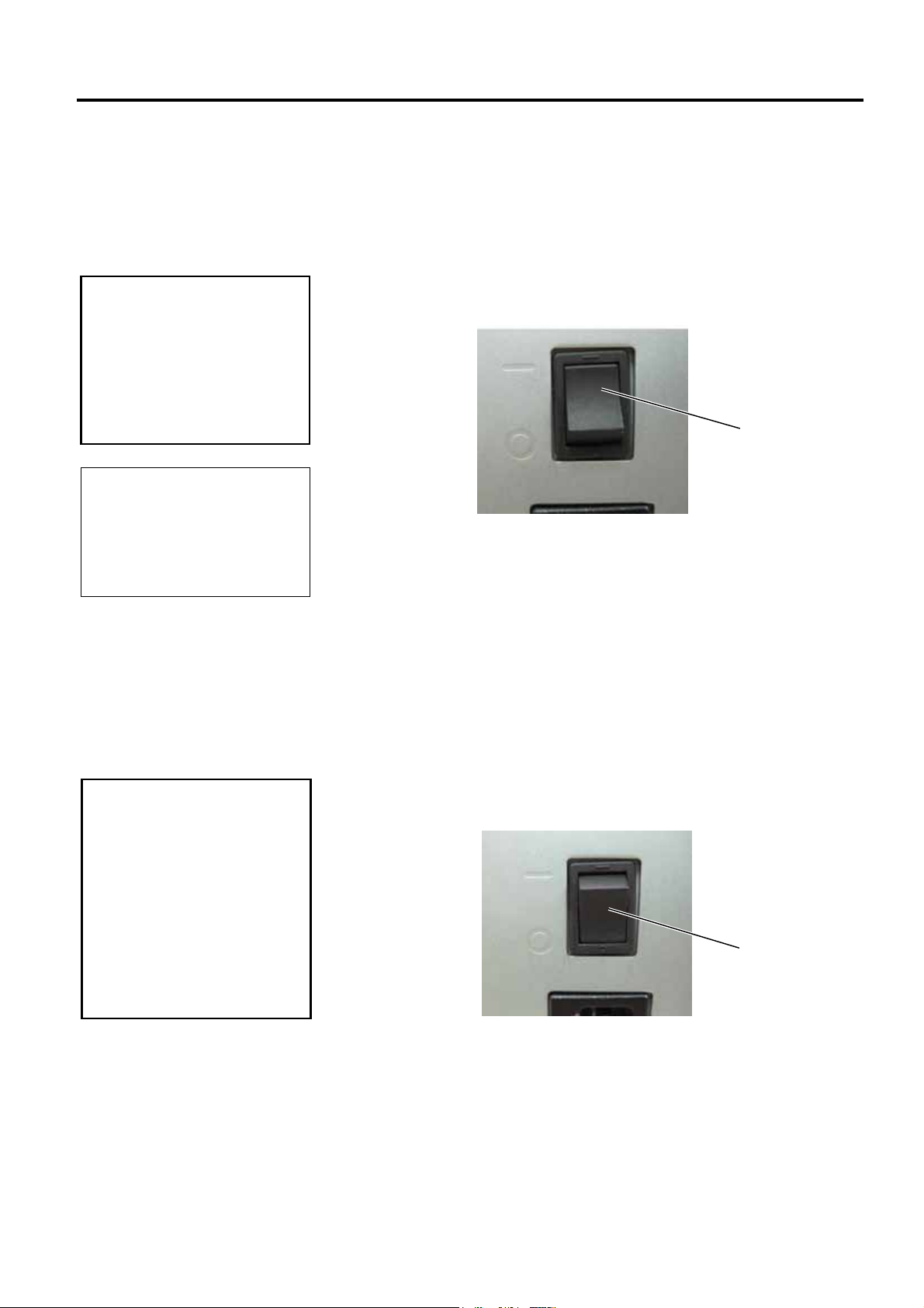
1. To turn ON the printer power, press the Power Switch as shown in the
diagram below. Note that ( | )
is the power ON side of the switch.
Power Switch
2. Check that the ON LINE message appears in the LCD Message
Display and that the ON LINE and POWER LED lights are
illuminated.
1. Before turning off the printer Power Switch verify that the ON LINE
message appears in the LCD Message Display and that the ON LINE
LED light is on and is not flashing.
2. To turn OFF the printer power press the Power Switch as shown in the
diagram below. Note that () is the power OFF side of the switch.
Power Switch
E2-13
Page 28
2. PRINTER SETUP ENGLISH VERSION EO1-33089
I
F
2.6 Printer Setting
Power ON
Power OFF
Depending on the settings of your host computer or an interface to be
used, it may be necessary to change the printer parameter settings.
Follow the procedures described below to change the printer parameter
settings to correspond to your environment.
ncorrect settings can cause the printer to function erroneously. If you have
any problems with the parameter settings, please contact your nearest
TOSHIBA TEC service representative.
or the settings this manual does not cover, please contact your nearest
TOSHIBA TEC service representative, or refer to the B-EX4T Series Key
Operation Specification.
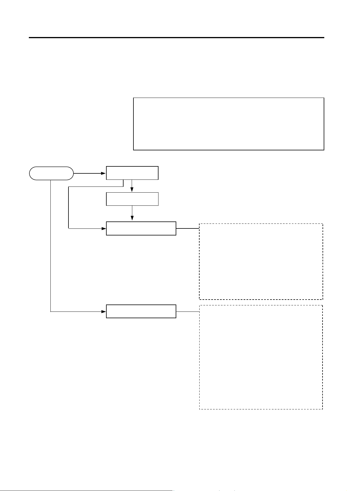
ONLINE Mode
[PAUSE]
PAUSE state
NOTE:
2.6 Printer Setting
User System Mode
Hold down [MODE]
Turn on the power while holding
down [FEED] & [PAUSE] or
[MODE].
System Mode
Hold down [RESTART]
• Reset
• Parameter setting (⇒Section 2.6.2)
• Fine adjustment (⇒Section 2.9)
• LAN/WLAN (⇒Section 2.6.3)
• BASIC (⇒Section 2.6.4)
• Z-MODE (⇒Section 2.6.5)
• Auto calibration (⇒Section 2.6.6)
• Dump mode (⇒Section 2.6.7)
• Log (⇒Section 2.6.8)
• Self diagnosis
• Parameter setting
• Fine adjustment
• Test print (⇒Section 2.8)
• Sensor adjustment
• RAM clear
• Interface setting (⇒Section 2.6.10)
• BASIC mode
• RFID setting
• Real Time Clock (⇒Section 2.6.11)
• Z-MODE
• USB memory
• Reset
E2-14
Page 29
2. PRINTER SETUP ENGLISH VERSION EO1-33089
2.6 Printer Setting
(Cont.)
FEED
MODE
LEFT
CANCEL
DOWN
PAUSE
RESTART
UP
RIGHT
ENTER
2.6.1 User System Mode
2.6 Printer Setting
Key functions in the system mode
Key Function
[MODE] Returns to the mode menu screen.
[CANCEL] or
[FEED]+[RESTAR]
[LEFT] Moves the cursor to the left.
[RIGHT] Moves the cursor to the right.
Returns to the upper hierarchy.
Displays a next screen. [ENTER] or [PAUSE]
Saves the setting and returns to the upper
hierarchy.
Moves the cursor upward.
Increases a value.
Moves the cursor downward.
Decreases a value.
(Note 2)
(Note 3)
(Note 1)
(Note 1)
(Note 3)
(Note 3)
[UP] or [RESTART]
[DOWN] or [FEED]
1. The cursor does not move any further when the selected option is listed
at the top or bottom.
2. The value does not increase or decrease any further when the selected
value is the upper or lower limit.
3. The cursor does not move any further when it is at the left-most or
right-most position.
4. Be careful the selected value does not become effective if the printer is
turned off without pressing the [ENTER] key.
NOTES:
How to enter the User System Mode
ONLINE
[PAUSE] Hold down [RESTART]
Hold down [MODE]
User System Mode
The User System Mode consists of the following menus.
<1>RESET
Used to reset the printer.
<2>PARAMETER SET (⇒ Section 2.6.2)
Used to set the printer parameters.
<3>ADJUST SET (⇒ Section 2.9)
Used to fine adjust the print start position, cut position, etc.
<4>LAN/WLAN (⇒ Section 2.6.3)
Used to enable or disable the LAN communication and SNMP.
<5>BASIC (⇒ Section 2.6.4)
Used to set the function of basic program when it is loaded to the
printer.
<6>Z-MODE (⇒ Section 2.6.5)
Same as BASIC
<7>AUTO CALIB (⇒ Section 2.6.6)
Used to enable or disable the automatic calibration function.
<8>DUMP MODE (⇒ Section 2.6.6)
Used to print the data in the receive buffer for debug.
<9>LOG (⇒ Section 2.6.7)
Used to save print logs in a USB memory.
E2-15
Page 30
2. PRINTER SETUP ENGLISH VERSION EO1-33089
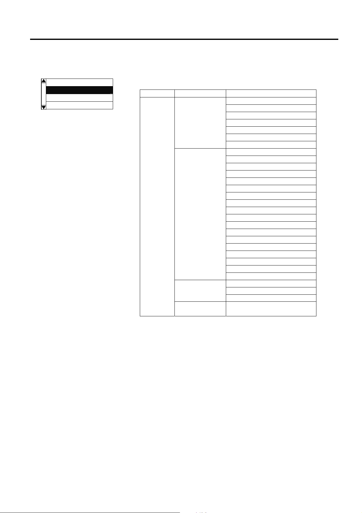
2.6.2 Parameter Setting
USER SYSTEM MODE
<1>RESET
<2>PARAMETER SET
<3>ADJUST SET
<4>LAN/WLAN
2.6 Printer Setting
The Parameter Set menu allows configuring printer parameter settings.
The following table shows the contents of the Parameter Set menu.
Contents of the Parameter Set Menu
Menu Sub menu Parameter
Printer Set MEDIA LOAD Parameter
set
FW/BK ACT
HU CUT/RWD
RBN SAVE
PRE PEEL OFF
BACK SPEED
Software Set FONT CODE
(Section 2.6.2.2) ZERO FONT
CODE
PEEL OFF STATUS
USB I/F STATUS
FEED KEY
KANJI CODE
EURO CODE
AUTO HD CHK
WEB PRINTER
RBN NEAR END
EX I/O
LBL/RBN END
MAX CODE
XML
THRESHOLD SELECT
ENERGY TYPE
PW SAVE TIME
Panel LCD LANGUAGE
(Section 2.6.2.3) DISPLAY
CONTRAST
Password PASSWORD
(Section 2.6.2.4)
(Section 2.6.2.1) FORWARD WAIT
E2-16
Page 31

2. PRINTER SETUP ENGLISH VERSION EO1-33089
2.6.2 Parameter Setting
(Cont.)
2.6 Printer Setting
2.6.2.1 Printer Set
(1) MEDIA LOAD
This parameter is to choose how the printer behaves to detect the
home position.
• OFF Media loading function is disabled (Same as a feed
by [FEED] key)
• STD When the printer is tuned on, reset in batch, or print
head is closed, the printer detects a gap/black mark
and feeds the paper from the sensor to the print start
position.
• ECO When the printer is tuned on, reset in batch, or print
head is closed, the printer detects a gap/black mark
and feeds the paper to the print start position based
on the label pitch.
• ECO+Bfeed Economy + backfeed
(2) FORWARD WAIT
This parameter is to choose whether or not to activate the auto forward
wait function. This function, used in the cut mode, automatically
feeds the media forward if there is more than 1-second idle time after
printing, to prevent the top edge of the media from curling.
• OFF Disables the auto forward feed wait
• ON Enables the auto forward feed wait
(3) FORWARD WAIT POS.
When the auto forward feed wait parameter is set to ON, the feed
amount can be fine adjusted.
+5.0mm
+4.9mm
(4) FW/BK ACT.
• MODE1 The printer waits for next issue with 13.7-mm media
• MODE2 When the thermal transfer method, Transmissive
.
-4.9mm
-5.0mm
forwarded.
sensor, and cut issue are selected, the printer feeds 6mm media backward, then waits for next issue with
3-mm media forwarded.
E2-17
Page 32

2. PRINTER SETUP ENGLISH VERSION EO1-33089
P
2.6.2 Parameter Setting
(Cont.)
The print head may not be raised
depending on the rise of the
solenoid’s temperature.
1. Do not enable the ribbon saving
function when the ribbon saving
module is not installed. Doing so
causes ribbon slack and print
failure.
2. The ribbon saving option must be
selected according to the head
lever position. Incorrect setting
may disable the proper ribbon
saving function.
re-strip function is automatically
enabled when the print speed is set to
10 ips.
NOTE:
NOTE:
NOTE:
2.6 Printer Setting
(5) HU CUT/RWD.
This parameter is to choose whether or not to activate the head up
action in the cut issue or to use the Rewinder in the batch or strip issue.
This function prevents ribbon smudges by raising the print head
during a reverse feed to the print start position.
• OFF Head up cut is not performed or the Rewinder is not
used.
• ON Head up cut is performed or the Rewinder is used.
(6) RBN SAVE
This parameter is to choose whether or not to activate the ribbon
saving function. This function enables reducing the ribbon loss
caused by taking up unused ribbon during non-print areas.
• TAG Enabled (When the head lever is set to TAG
position.)
• LABEL Enabled (When the head lever is set to Label
position)
• OFF Disabled.
(7) PRE PEEL OFF
This parameter is to choose whether to activate the pre-strip function.
When this parameter is set to ON, the top edge of a label is separated
(pre-stripped) from the backing paper before the label is printed. This
function is intended to make the strip issue easier in the case the labels
are hard to strip due to the label intensity, adhesive power, or the
printing speed.
• OFF Disables pre peel off
• ON Enables pre peel off
(8) BACK SPEED
This parameter is to choose a back feed speed.
In the strip issue, the back feed sped of 3 ips may cause a shortage of
feed amount due to a lack of torque, slippery media surface, etc. In
such case, reduce the back feed speed to 2 ips to secure the feed
amount.
• STD 3ips
• LOW 2ips
E2-18
Page 33

2. PRINTER SETUP ENGLISH VERSION EO1-33089
z
K
P
B
2.6.2 Parameter Setting
(Cont.)
NOTE:
The following fonts do not support a
ero with a slash.
Therefore, even if a zero with a slash is
specified, a zero without a slash is
used.
[Bit map fonts]
OCR-A, OCR-B, GOTHIC725 Black,
anji, Chinese character
[Outline fonts]
rice fonts 1, 2, and 3, DUTCH801
old, BRUSH738 Regular,
GOTHIC725 Black, TrueType font
2.6 Printer Setting
2.6.2.2 Software Set
(1) FONT CODE
This parameter is to choose a character code used for printing. Printed
characters differ depending on the chosen character code and font.
• PC-850
• PC-852
• PC-857
• PC-8
• PC-851
• PC-855
• PC-1250
• PC-1251
• PC-1252
• PC-1253
• PC-1254
• PC-1257
• LATIN9
• Arabic
• PC-866
• UTF-8
(2) ZERO FONT
This parameter is to choose the way to indicate zero between “0” and
Ø”.
“
• 0 No slash used
• Ø Slash used
(3) CODE
This parameter is to choose a command control code.
• AUTO Automatically selected.
• {,|,}
• ESC, LF, NUL
• MANUAL Control code is specified by a user.
(4) MANUAL
When MANUAL is selected for the CODE parameter, you need to
specify each of the control codes 1 to 3 with hex. code.
FF
FE
CODE1 CODE2 CODE3
01
00
E2-19
Page 34

2. PRINTER SETUP ENGLISH VERSION EO1-33089
2.6.2 Parameter Setting
(Cont.)
2.6 Printer Setting
(5) PEEL OFF STATUS
This parameter is to choose whether the printer sends a strip wait
status to the host in response to a status request command.
• OFF
• ON
(6) USB I/F STATUS
This parameter is to choose whether or not to return a response to the
host via USB.
• OFF Disables sending a response via USB
• ON Enables sending a response via USB
(7) FEED KEY
This parameter is to choose the function of the FEED key.
• FEED Feeds one label.
• PRINT Prints data in the image buffer (The last printed data)
(8) KANJI CODE
This parameter is to choose a KANJI code.
• TYPE1 Windows code
• TYPE2 Original code
After selecting a Kanji code, press [ENTER] key
(9) EURO CODE
This parameter is to choose a Euro code (€).
“20” to “FF” (Specify the hex code in 2 bytes of ASCII code)
FF
FE
21
20
(10) AUTO HD CHK
This parameter is to choose whether to perform the auto print head
check at a power on time.
• OFF Auto print head check is not performed.
• ON Auto print head check is performed.
E2-20
Page 35

2. PRINTER SETUP ENGLISH VERSION EO1-33089
F
E
2.6.2 Parameter Setting
(Cont.)
NOTE:
Since a detected remaining
ribbon length has some margin of
error, use the specified length as
a guide.
NOTE:
The type specified by the
command may differ from the
actual mode, depending on the
status of this parameter. Also,
the data transmission method
differs partly.
or details, refer to the External
quipment Interface
Specification.
2.6 Printer Setting
(11) WEB PRINTER
This parameter is to choose whether to use the printer as a web printer.
When the web printer is enabled, the status of the printer connected to
a network can be monitored through the web browser.
• OFF Disables web printer function
• ON INTERNAL Enables web printer function (using an internal
memory)
• ON EXTERNAL Enables web printer function (using an external
memory)
(12) RBN NEAR END
This parameter is to choose the remaining ribbon length where the
ribbon near end is detected.
• OFF Ribbon near end is not detected.
• 30m Ribbon near end is detected when the remaining
ribbon is 30-m long. (Equivalent to ribbon diameter
of 38 mm)
• 70m Ribbon near end is detected when the remaining
ribbon is 70-m long. (Equivalent to ribbon diameter
of 43 mm)
(13) EX.I/O
This parameter is to choose a type of the expansion I/O interface
operating mode. This parameter needs to be set depending on the
expansion I/O control specification of the device to be connected via
the expansion I/O interface.
• TYPE1 Standard mode
• TYPE2 In-line mode
(14) LBL/RBN END
This parameter is to choose a printer processing when a label end or
ribbon end is detected.
• TYPE1 When a label/ribbon end is detected in the middle of
printing, the printer immediately stops printing.
• TYPE2 Selectable only when the ribbon saving function is
not activated.
When a label/ribbon end is detected in the middle of
printing, the printer prints the half-finished label as
far as possible, and stops when the next label is at the
home position.
(15) MAXI CODE
This parameter is to choose a Maxicode specification.
• TYPE1 Compatible with the current version
• TYPE2 Special specification
E2-21
Page 36

2. PRINTER SETUP ENGLISH VERSION EO1-33089
2.6.2 Parameter Setting
(Cont.)
2.6 Printer Setting
(16) XML
This parameter is to choose a type of XML data to be printed.
• OFF Disables XML data printing.
• STD Standard specification
• ORACLE Oracle
• SAP SAP
• STD EXT Standard specification (External memory)
• ORACLE EXT Oracle using an external memory
• SAP EXT SAP using an external memory
(17) THRESHOLD SELECT
This parameter is to choose which threshold value for the media
sensor to validate.
• REFLECT Reflective sensor
• TRANS. Transmissive sensor
Then, choose which value to use.
• MANUAL SET Threshold set in the Threshold mode takes
effect.
• COMMAND SET Threshold set by command takes effect.
(18) ENERGY TYPE
This parameter is to choose an energy level applied to the print head.
• TRANSFER Thermal transfer print method → c
• DIRECT Thermal direct print method → d
c When TRANSFER is selected for the Energy type parameter,
choose a ribbon type.
• Semi resin1 Semi-resin 1
• Semi resin2 Semi-resin 2
• Resin1 Resin 1
• Resin2 Resin 2
• Reserve1 to Reserve6 Reserved
d When DIRECT is selected for the Energy type parameter
• Standard Standard
• Reserve1 to Reserve9 Reserved
(19) PW SAVE TIME
This parameter is to set the length of time until the printer enters the
sleep mode. (Unit: minute)
240 min.
239 min.
2 min.
1 min.
E2-22
Page 37

2. PRINTER SETUP ENGLISH VERSION EO1-33089
p
J
E
F
2.6.2 Parameter Setting
(Cont.)
The language displayed on
anel is Japanese when
apanese is selected, and
nglish when English, German,
rench, Dutch, Spanish, Italian;
or Portuguese is selected.
NOTE:
2.6 Printer Setting
2.6.2.3 PANEL
(1) LCD LANGUAGE
This parameter is to choose a language in which the LCD message is
displayed.
• ENGLISH
• GERMAN
• FRANCH
• DUTCH
• SPANISH
• JAPANESE
• ITALIAN
• PORTUGUESE
(2) MACHINE NAME
This parameter is to choose whether to display the model name.
• OFF Hidden
• ON Displayed
(3) PRINT PAGE
This parameter is to choose whether to display the number of labels
printed.
• OFF Hidden
• ON Displayed
(4) IP ADDRESS
This parameter is to choose whether to display the IP address.
• OFF Hidden
• ON Displayed
(5) CONTRAST
This parameter is to adjust the contrast of the LCD.
50
High
48
26
24
Low
E2-23
Page 38

2. PRINTER SETUP ENGLISH VERSION EO1-33089
2.6.2 Parameter Setting
(Cont.)
2.6.3 Enabling LAN/WLAN
USER SYSTEM MODE
<1>RESET
<2>PARAMETER SET
<3>ADJUST SET
<4>LAN/WLAN
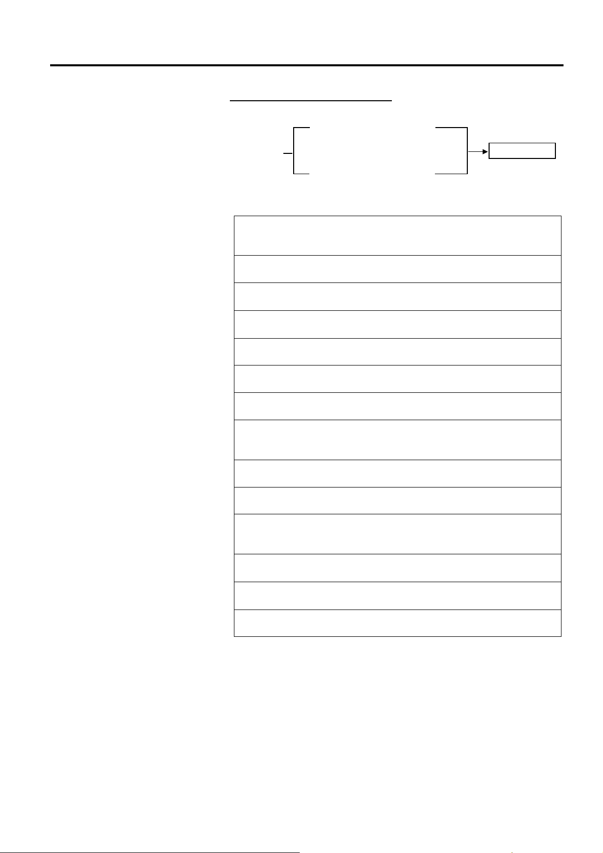
2.6.4 Basic Program Setting
USER SYSTEM MODE
<2>PARAMETER SET
<3>ADJUST SET
<4>LAN/WLAN
<5>BASIC
2.6 Printer Setting
2.6.2.4 PASSWORD
(1) PASSWORD
This parameter is for system administrator only. Please do not change
the setting for this parameter.
The LAN/WLAN menu allows selecting whether or not to enable the
LAN communication and SNMP.
(1) LAN/WLAN
• OFF LAN and Wireless LAN are disabled.
• ON (AUTO) Automatically selected.
• ON (LAN) LAN is enabled.
• ON (WLAN) Wireless LAN is enabled.
(2) SNMP
• OFF SNMP is disabled.
• ON SNMP is enabled.
The following table shows the contents of the Basic program setting
menu.
Contents of the Basic Program Setting Menu
Menu Sub menu
BASIC BASIC
FILE MAINTENANCE
TRACE
EXPAND MODE
(1) BASIC
This parameter is to choose whether to enable the BASIC program.
• OFF Disables BASIC program.
• ON Enables BASIC program.
(2) FILE MAINTENANCE
The block number and BASIC program file name (up to 12 characters)
stored in the BASIC program storage area are displayed. If file name
exceeds 12 characters, the overflowing characters are not displayed.
When no file is stored, a hyphen (“-“) is displayed in place of the file
name.
E2-24
Page 39

2. PRINTER SETUP ENGLISH VERSION EO1-33089
2.6.4 Basic Program Setting
(Cont.)
2.6.5 Enabling Z-Mode
USER SYSTEM MODE
<3>ADJUST SET
<4>LAN/WLAN
<5>BASIC
<6>Z-MODE
2.6 Printer Setting
(3) TRACE
This parameter is to choose whether to enable tracing the BASIC
program.
• OFF Disables tracing the BASIC program.
• ON Enables tracing the BASIC program.
(4) EXPAND MODE
The printer switches the mode to execute the BASIC program.
The Z-Mode menu allows selecting whether or not to enable the Z-Mode
(Zebra converter)
.
(1) Z-MODE
• OFF Z-Mode is disabled.
• ON SETTING OFF Z-Mode is enabled. BASIC system mode
program is not started immediately.
• ON SETTING ON Z-Mode is enabled. BASIC system mode
program is started immediately.
E2-25
Page 40

2. PRINTER SETUP ENGLISH VERSION EO1-33089
2.6.6 Automatic Calibration
USER SYSTEM MODE
<4>LAN/WLAN
<5>BASIC
<6>Z-MODE
<7>AUTO CALIB
2.6 Printer Setting
The Auto Calibration menu allows selecting whether or not to enable the
automatic calibration at a power on time. When the automatic calibration
is activate, the printer feeds the media for about 160 mm each time the
power is turned on or the top cover is opened, to detect a print start
position.
(1) AUTO CALIB
• OFF Disabled.
• ON TRANS. Enabled. (Transmissive sensor)
• ON REFLECT Enabled. (Reflective sensor)
• ON ALL Enabled. (Transmissive & Reflective
sensors)
• ON TRANS.+Bfeed Auto calibration + back feed
(Transmissive sensor)
• ON REFLECT+Bfeed Auto calibration + back feed
(Reflective sensor)
• ON ALL+Bfeed Auto calibration + back feed
(Transmissive & Reflective sensors)
NOTES:
1. When AUTO CALIB is enabled, an automatic calibration is performed at
an open/close of the print head and at a power on time.
2. When AUTO CALIB is enabled, the media length, effective print length,
sensor type, and whether to use ribbon or not specified by commands are
ignored.
3. This function is available only when the media pitch is 10.0 mm to 150.0
mm.
4. When the printer cannot detect the second black mark/gap, it will
continue to feed the media for up to 500.0mm. If this does not work, the
printer will stop, resulting in a paper jam.
5. During an automatic calibration, the printer also feeds the ribbon. Even
if the ribbon is not loaded, no error results. However, the print condition
will be automatically changed to “No ribbon” after the calibration ends.
6. When the cutter is installed and a previous issue was performed in cut
issue mode, the media is cut and ejected after an automatic calibration
completes.
7. When a label end or a head open occurs during an automatic calibration,
the printer stops, resulting in an error. Loading new media and closing
the print head can clear the error and resume the automatic calibration.
8. The media is fed backward after an auto calibration is performed if the
reverse feed is enabled.
E2-26
Page 41

2. PRINTER SETUP ENGLISH VERSION EO1-33089
I
2.6.7 Dump Mode Setting
USER SYSTEM MODE
<5>BASIC
<6>Z-MODE
<7>AUTO CALIB
<8>DUMP MODE
NOTE:
f a file with the same name
already exists in the USB
memory, it will be overwritten.
2.6 Printer Setting
In the Dump Mode, data in the receive buffer are printed. Data are
expressed in hexadecimal values. This operation allows verification of
the programming commands or debug of the program.
(1) BUFFER
This parameter is to choose the receive buffer to dump.
• RS-232C RS-232C receive buffer
• CENTRONICS Centronics receive buffer
• LAN Network I/F receive buffer
• BASIC1 BASIC Interpreter:
I/F → Interpreter buffer
• BASIC2 BASIC Interpreter:
Interpreter buffer → I/F
• USB USB receive buffer
• RFID RFID receive buffer
(2) DUMP LIST
This parameter is to choose the output destination.
• USB MEMORY Saves in the USB memory. → c
• PRINT Prints out → d
c When USB MEMORY is selected:
A file is automatically created in the USB memory and named in the
following format based on the printer model and saved date.
/ATA0/DUMP/B-EX4T1_DUMP_1007291030.BIN
(e.g. B-EX4T Type1, 10:30, July 29, 2010)
d When PRINT is selected:
Choose a printing method.
• ON DEMAND Prints 166 lines of data (approx. 50 cm), then
stops. Subsequent data is printed when the
[ENTER] key is pressed.
• ALL Prints all data in the receive buffer.
E2-27
Page 42

2. PRINTER SETUP ENGLISH VERSION EO1-33089
m
I
A
p
2.6.7 Dump Mode Setting
(Cont.)
Print Conditions
• Printing width: 3.9 inches
(Approx. 100 mm)
• Sensor selection: None
• Print speed: 6”/sec. (203 dpi)
5”/sec. (305 dpi)
• Printing mode: Depends on the
selection in use.
• 16 bytes/line
• Data is printed in the order fro
the new one to the old one.
• Data specified by the receive
buffer write pointer will be
printed in boldface.
The data in the receive buffer is printed as follows.
00 00 00 00 00 00 00 00 00 00 00 00 00 00 00 00 ................
00 00 00 00 00 00 00 00 00 00 00 00 00 00 00 00 ................
00 00 00 00 00 00 00 00 00 00 00 00 00 00 00 00 ................
00 00 00 00 00 00 00 00 00 00 00 00 00 00 00 00 ................
7B 41 58 3B 2B 30 30 30 2C 2B 30 30 30 2C 2B 30 {AX;+000,+000,+0
30 7C 7D 7B 44 30 37 37 30 2C 31 31 30 30 2C 30 0|}{D0760,1100,0
37 34 30 7C 7D 7B 43 7C 7D 7B 4C 43 3B 30 30 33 740|}{C|}{LC;003
30 2C 30 30 32 30 2C 30 30 33 30 2C 30 36 36 30 0,0020,0030,0660
2C 30 2C 32 7C 7D 7B 4C 43 3B 30 30 37 30 2C 30 0,2|}{LC;0070,0
30 32 30 2C 30 30 37 30 2C 30 36 36 30 2C 30 2C 020,0070,0660,0,
39 7C 7D 7B 4C 43 3B 30 30 35 30 2C 30 30 32 30 9|}{LC;0050,0020
44 45 46 47 48 49 4A 7C 7D 7B 50 43 31 30 3B 30 DEFGHIJ|}{PC10;0
33 35 30 2C 30 34 30 30 2C 31 2C 31 2C 4B 2C 30 350,0400,1,1,K,0
30 2C 42 3D 41 42 43 44 65 66 67 68 69 6A 6B 6C 0,B=ABCDefghijkl
6D 6E 6F 70 7C 7D 7B 50 56 30 32 3B 30 33 33 30 mnop|}{PV02;0330
2C 30 36 36 30 2C 30 32 37 30 2C 30 32 35 30 2C 0660,0270,0250,
41 2C 30 30 2C 42 3D 42 7C 7D 7B 50 56 30 33 3B A,00,B=B|}{PV03;
3B 30 39 30 30 2C 30 31 38 30 2C 54 2C 48 2C 30 ;0900,0180,T,H,0
35 2C 41 2C 30 3D 31 32 33 34 35 36 37 38 39 30 5,A,0=1234567890
41 42 43 44 45 7C 7D 00 00 00 00 00 00 00 00 00 ABCDE|}.........
:
:
:
:
:
:
:
:
:
:
:
:
Receive Buffer Size
2.6 Printer Setting
NOTE:
f an error occurs while printing,
the printer stops printing and
shows an error message.
fter clearing the error, the
rinter does not resume printing
automatically.
Interface 203 dpi 305 dpi
RS-232C 6MB (393216 lines) 6MB (393216 lines)
Centronics 6MB (393216 lines) 6MB (393216 lines)
LAN 6MB (393216 lines) 6MB (393216 lines)
BASIC 1 8KB (512 lines) 8KB (512 lines)
BASIC 2 8KB (512 lines) 8KB (512 lines)
USB 6MB (393216 lines) 6MB (393216 lines)
RFID 8KB (512 lines) 8KB (512 lines)
Required Media Length
Interface 203 dpi 305 dpi
RS-232C 1189.2 m 1189.2 m
Centronics 1189.2 m 1189.2 m
LAN 1189.2 m 1189.2 m
BASIC 1 2 m 2 m
BASIC 2 2 m 2 m
USB 1189.2 m 1189.2 m
RFID 2 m 2 m
*: Media length required for printing all data in the receive buffer.
E2-28
Page 43

2. PRINTER SETUP ENGLISH VERSION EO1-33089
I
2.6.8 Logging
USER SYSTEM MODE
<6>Z-MODE
<7>AUTO CALIB
<8>DUMP MODE
<9>LOG
f a file with the same name
already exists in the USB
memory, it will be overwritten.
NOTE:
2.6 Printer Setting
The Log menu allows saving print logs in a USB memory.
(1) LOG
• PRINTER TO USB Saves print logs in the USB memory.
A file is automatically created in the USB memory and named in the
following format based on the printer model and saved date.
/ATA0/LOG/B-EX4T1_LOG_1007291030.TXT
(e.g. B-EX4T Type1, 10:30, July 29, 2010)
E2-29
Page 44
2. PRINTER SETUP ENGLISH VERSION EO1-33089
2.6.9 System Mode
2.6 Printer Setting
How to enter the System Mode
Power OFF
Power ON while holding down
[FEED]&[PAUSE]
System Mode
Power ON while holding down
[MODE]
The System Mode consists of the following menus.
<1>DIAG.
Used to check and print the printer system information and
maintenance counter status.
<2>PARAMETER SET (⇒ Section 2.6.2)
Used to set the parameters for each printer function.
<3>ADJUST SET (⇒ Section 2.9)
Used to fine adjust the print position, cut position, print tone, etc.
<4>TEST PRINT (⇒ Section 2.8)
Used to perform print tests.
<5>SENSOR ADJUST
Used to check the sensor statuses and set each sensor.
<6>RAM CLEAR
Used to perform a RAM clear. DO NOT USE this menu.
<7>INTERFACE (⇒ Section 2.6.10)
Used to set the interface parameters.
<8>BASIC (⇒ Section 2.6.4)
Used to set the function of basic program when it is loaded to the
printer.
<9>FOR FACTORY
Used for an in-process inspection. DO NOT USE this menu.
<10>RFID
Used to set RFID related parameters.
<11>RTC (⇒ Section 2.6.11)
Used to set the date and time of the real time clock, enable or disable
the low battery check, and choose a real time renewal timing.
<12>Z-MODE (⇒ Section 2.6.5)
Same as BASIC
<13>USB MEMORY (⇒ Section 2.6.12)
Used to copy data to/from USB memory.
<14>RESET
Used to reset the printer.
E2-30
Page 45

2. PRINTER SETUP ENGLISH VERSION EO1-33089
2.6.10 Interface Setting
SYSTEM MODE
<4>TEST PRINT
<5>SENSOR ADJUST
<6>RAM CLEAR
<7>INTERFACE
2.6 Printer Setting
The Interface menu allows configuring printer interface parameters.
The following table shows the contents of the Interface menu.
Contents of the Interface Menu
Menu Sub menu Parameter
NETWORK LAN/WLAN Interface
SNMP
SETTING
BASIC INFORMATION
IP ADDRESS
GATEWAY ADDRESS
SUBNET MASK
SOCKET PORT
PORT NUMBER
DHCP
DHCP CLIENT ID
DHCP HOST NAME
WLAN STANDARD
WLAN MODE
DEFAULT KEY
802.11B CHANNEL
802.11B BAUD
802.11G CHANNEL
802.11G BAUD
WLAN POWER SAVE
WINS
WINS ADDRESS
LPR
USB
RS-232C SPEED
DATA LENGTH
STOP BIT
PARITY
CONTROL
CENTRO. ACK/BUSY
INPU PRIME
PLUG & PLAY
E2-31
Page 46

2. PRINTER SETUP ENGLISH VERSION EO1-33089
2.6.10 Interface Setting
(Cont.)
2.6.10.1 Network Setting
(1) LAN/WLAN
• OFF LAN and Wireless LAN are disabled.
• ON (AUTO) Automatically selected.
• ON (LAN) LAN is enabled.
• ON (WLAN) Wireless LAN is enabled.
(2) SNMP
• OFF SNMP is disabled.
• ON SNMP is enabled.
(3) BASIC INFORMATION
The following information is displayed.
IP Address
Gateway address
Subnet mask
Socket port status
Socket port number
(4) IP ADDRESS
(5) GATEWAY ADDRESS
192 020 168 010
192 020 168 010
(6) SUBNET MASK
255 255 255 000
(7) SOCKET PORT
• OFF Socket port is disabled.
• ON Socket port is enabled.
2.6 Printer Setting
E2-32
Page 47

2. PRINTER SETUP ENGLISH VERSION EO1-33089
2.6.10 Interface Setting
(Cont.)
(8) PORT NUMBER
65535
65534
00001
00000
(9) DHCP
• OFF DHCP is disabled.
• ON DHCP is enabled.
(10) DHCP CLIENT ID
• ASCII DHCP client ID is entered with ASCII code. → c
• HEX DHCP client ID is entered with Hex. code. → d
c When ASCII is selected:
Enter 64 characters with ASCII code.
d When HEX is selected:
Enter 64 characters with Hex. code.
(11) DHCP HOST NAME
Enter 32 characters with ASCII code.
(12) WLAN STANDARD
• 11b/g
• 11b
• 11g
2.6 Printer Setting
E2-33
Page 48

2. PRINTER SETUP ENGLISH VERSION EO1-33089
2.6.10 Interface Setting
(Cont.)
2.6 Printer Setting
(13) WLAN MODE
This parameter is to choose the connection mode and authentication.
ADHOC OPEN OFF
WEP40
WEP104
SHARED Not used WEP40
WEP104
INFRA OPEN OFF
WEP40
WEP104
SHARED WEP40
WEP104
802.1x OPEN TLS WEP40
WEP104
TTLS WEP40
WEP104
LEAP WEP40
WEP104
PEAP WEP40
WEP104
MD5 WEP40
WEP104
EAP-FAST WEP40
WEP104
SHARED KEY EAP-MD5 WEP40
WEP104
NETWORK EAP WEP40
WEP104
WPA OPEN TLS
TTLS
LEAP
PEAP
EAP-FAST
NETWORK EAP
WPA-PSK
WPA2 OPEN TLS
TTLS
LEAP
PEAP
EAP-FAST
NETWORK EAP
WPA2-PSK
E2-34
Page 49

2. PRINTER SETUP ENGLISH VERSION EO1-33089
2.6.10 Interface Setting
(Cont.)
(14) DEFAULT KEY
This parameter is to choose a WEP key.
4
1
(15) 802.11b CHANNEL
This parameter is to choose a channel for 802.11b WLAN.
14
1
(16) 802.11b BAUD
This parameter is to choose a baud rate for 802.11b WLAN.
• 11M
• 5.5M
• 2M
• 1M
(17) 802.11g CHANNEL
This parameter is to choose a channel for 802.11g. WLAN.
14
1
(18) 802.11g BAUD
This parameter is to choose a baud rate for 802.11g WLAN.
• 54M
• 48M
• 36M
• 24M
• 18M
• 12M
• 9M
• 6M
• 11M
• 5.5M
• 2M
• 1M
2.6 Printer Setting
E2-35
Page 50

2. PRINTER SETUP ENGLISH VERSION EO1-33089
2.6.10 Interface Setting
(Cont.)
2.6 Printer Setting
(19) WLAN POWER SAVE
This parameter is to choose whether to enable the power save function
while WLAN communication.
• OFF Power save function is disabled.
• ON Power save function is enabled.
(20) WINS
• OFF WINS is disabled.
• ON (MANUAL) WINS is enabled. (Manual)
• ON (DHCP) WINS is enabled. (DHCP)
(21) WINS ADDRESS
The WINS address is displayed.
(22) LPR
• OFF LPR is disabled.
• ON LPR is enabled.
2.6.10.2 USB
(1) USB SERIAL ID
• OFF USB serial ID is disabled.
• ON USB serial ID is enabled.
2.6.10.3 RS-232C
(1) SPEED
• 2400 bps
• 4800 bps
• 9600 bps
• 19200 bps
• 38400 bps
• 115200 bps
E2-36
Page 51

2. PRINTER SETUP ENGLISH VERSION EO1-33089
2.6.10 Interface Setting
(Cont.)
(2) DATA LENGTH
• 8 bits
• 7 bits
(3) STOP BIT
• 1 bit
• 2 bits
(4) PARITY
• NONE
• EVEN
• ODD
(5) CONTROL
• XON+READY AUTO XON/XOFF mode
• XON+XOFF AUTO XON/XOFF+READY/BUSY mode
• READY/BUSY RTS RTS mode
• XON+XOFF XON/XOFF mode
• READY/BUSY READY/BUSY mode
2.6.10.4 CENTRO.
2.6 Printer Setting
(1) ACK/BUSY
This parameter is to choose an ACK/BUSY timing.
• TYPE1 A rise of ACK signal and a release of BUSY occur at the
same time.
• TYPE2 A fall of ACK signal and a release of BUSY occur at the
same time.
(2) INPUT PRIME
This parameter is to choose whether to enable a rest operation when
INIT signal is ON.
• OFF
• ON
(3) PLUG & PLAY
• OFF
• ON
E2-37
Page 52

2. PRINTER SETUP ENGLISH VERSION EO1-33089
2.6.11 Real Time Clock (RTC)
SYSTEM MODE
<8>BASIC
<9>FOR FACTORY
<10>RFID
<11>RTC
2.6 Printer Setting
The RTC menu allows setting the date and time, enabling the battery
check function, and selecting the RTC data renewal timing while printing.
The Real Time Clock Setting is effective only when an optional RTC &
USB Host Interface Card, B-EX700-RTC-QM-R, is installed.
(1) DATE TIME
This parameter is to set date and time.
YY/MM/DD
Hh:mm:ss
(2) BATTERY CHECK
00 00 00 [RIGHT]
00 00 00
This parameter is to choose whether or not to enable the low battery
check function.
• OFF
• ON
(3) RENEWAL
This parameter is to choose when date and time are updated while
printing.
• BATCH As the real time clock data is read only for the
first media in a batch the same time is printed on
the all media.
• PAGE As the real time clock data is read at the start of
printing each media, a real time can be printed on
each media.
E2-38
Page 53

2. PRINTER SETUP ENGLISH VERSION EO1-33089
I
2.6.12 Copying Data to/from USB Memory
SYSTEM MODE
<10>RFID
<11>RTC
<12>Z-MODE
<13>USB MEMORY
NOTE:
f a file with the same name
already exists in the USB
memory, it will be overwritten.
2.6 Printer Setting
The USB Memory menu allows copying data from a USB memory to the
printer and saving data from the printer to a USB memory.
USB memory can be used only when an optional RTC & USB Host
Interface Card, B-EX700-RTC-QM-R, is installed.
(1) USB TO PRINTER
This parameter is to copy data from a USB memory to the printer.
• COPIED DATA Data
including firmware (BOOT/MAIN/
CG/KANJI/HTML), storage area information,
and parameter settings
• CONFIG FILE File containing firmware (BOOT/MAIN/
CG/KANJI/HTML)
1. When the file selection screen is displayed, choose a file to be copied.
2. The confirmation message is displayed.
3. The data is read from the USB memory. It takes 3 to 5 minutes to
read all information.
(2) PRINTER TO USB
This parameter is to save the firmware (BOOT/MAIN/CG/
KANJI/HTML), storage area information, and parameter settings to a
USB memory.
• ALL
1. The confirmation message is displayed.
2. The data is copied to the USB memory. It takes approx. 40 seconds to
save all information.
A file is automatically created in the USB memory and named in the
following format based on the printer model and saved date.
/ATA0/SYSTEM/B-EX4T1-T1105.DAT
(e.g. B-EX4T Type1, 305 dpi model, November 5)
E2-39
Page 54

2. PRINTER SETUP ENGLISH VERSION EO1-33089
2.7 Installing the Printer Drivers
2.7 Installing the Printer Drivers
2.7.1 Introduction
This chapter describes how to install the TOSHIBA printer driver for the TOSHIBA bar code printer on your
Windows host computer; install and delete the printer driver, the procedure for adding the LAN port, cautions
and limitations.
2.7.2 General Description
(1) Features
Once you install the TOSHIBA printer driver on your Windows host computer, you can use the TOSHIBA
bar code printer, as well as the easy-to-use general printers.
You can use this printer by connecting a USB cable, or a LAN cable to your host computer.
(2) System Requirements
To install the TOSHIBA printer driver on your host computer, the following system and environment are
required:
• Operating system: Windows 2000, Windows XP, Windows Server 2003, Windows Vista, Windows
Server 2008, Windows 7 or Windows Server 2008 R2
• Hardware: A DOS-/V (IBM PC/AT compatible) machine running an above operating system.
• Interface: • USB interface
• LAN interface
2.7.3 Installing the Printer Driver
The installation procedure of this printer driver differs depending on the printer models and the connection
methods. Follow the procedure for the appropriate condition to install the printer driver.
If the older version of this printer driver has been already installed, be sure to uninstall it first, restart the printer,
and install the latest printer driver.
See Section 2.7.10 Uninstalling the Printer Driver.
Installation method for each operating system
Connection method
OS
Plug and Play is not used. Plug and Play is used.
LAN USB
Windows 2000 Section 2.7.7 Installation under Windows 2000
Windows XP
Windows Server
2003
Windows Vista Section 2.7.6 Installation under
Section 2.7.5 Installation under
Windows 2000/XP/Server2003
Windows Vista/Server2008/7
(USB interface with plug and play enabled)
Section 2.7.8 Installation under Windows
XP/Server2003 (USB interface with plug and play
enabled.)
Section 2.7.9 Installation under Windows
Vista/Server2008/7 (USB connection with plug and
play enabled)
E2-40
Page 55

2. PRINTER SETUP ENGLISH VERSION EO1-33089
2.7 Installing the Printer Drivers
2.7.4 Preparation for Installation
(1) Access Toshiba TEC web site at the following address and download the printer driver install file
“TPCL72M2E.exe” to the local disc.
http://www.toshibatec-ris.com/products/barcode/download/driver_agreement.html
Note: If you do not agree with the Software License Agreement, you cannot download the file.
(2) Double-click the downloaded “TPCL72M2E.exe”,
and the “TPCL PRINTER DRIVER – Installshield
Wizard” is displayed. Click the [Next] button.
Note: Log on as the user with administrative
privilege.
When the User Account Control screen is
displayed under Windows
Vista/Server2008/7/Server2008R2, click on
the “Allow”.
E2-41
Page 56

2. PRINTER SETUP ENGLISH VERSION EO1-33089
(3) The “Software License Agreement” is displayed.
Select “I accept the terms of the license
agreement” and click the [Next] button.
Note: If you do not agree with the Software
License Agreement, you cannot download
the file.
(4) When you click the [Install] button, the printer
driver install file is created in “C:\TEC_DRV”.
Note: The folder name cannot be changed from
“C:\TEC_DRV”.
2.7 Installing the Printer Drivers
(5) When the installation is completed, click the
[Finish] button.
Note: In the case of Windows Vista/Server2008/7/
Server2008R2, the screen on the right will
appear. Click the “Install this driver
software anyway”.
E2-42
Page 57

2. PRINTER SETUP ENGLISH VERSION EO1-33089
2.7 Installing the Printer Drivers
2.7.5 Installation under Windows 2000/XP/Server2003
(1) Turn on the PC.
Note: Log on as the user with administrative privilege.
(2) Select the “Start”, “Printer and FAX” to show the printer folder.
Supplement: In the case of Windows 2000, select “Start”, “Setting”, and “Printer”. If the “Printer and
FAX” folder is not found, click the “Control Panel” and select the “Printer and FAX”.
In the case of the category view, click the “Printer and Other Hardware” and select the
“Printer and FAX”.
(3) Select the “Add printer” from the File menu. The “Add Printer Wizard” is displayed.
(4) Click the [Next] button in the “Add Printer
Wizard”.
E2-43
Page 58
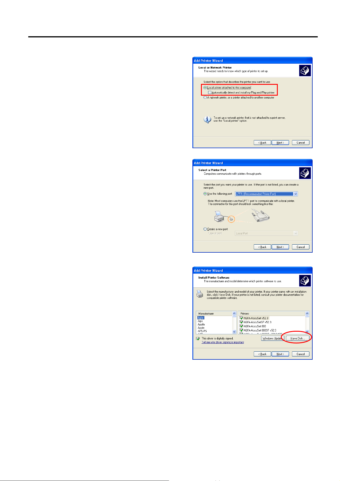
2. PRINTER SETUP ENGLISH VERSION EO1-33089
(5) Select the “Local printer attached to this
computer” and click the [Next] button.
Note: Do not check the “Automatically detect and
install my Plug and Play printer” checkbox.
Even in the case of specifying the network printer
or a printer connected to other PC, be sure to
choose the local printer in this step. This setting is
changed after the installation is completed.
(6) Specify a printer port and click the [Next] button.
2.7 Installing the Printer Drivers
(7) When the “Install Printer Software” screen
appears, click the [Have Disk] button.
E2-44
Page 59
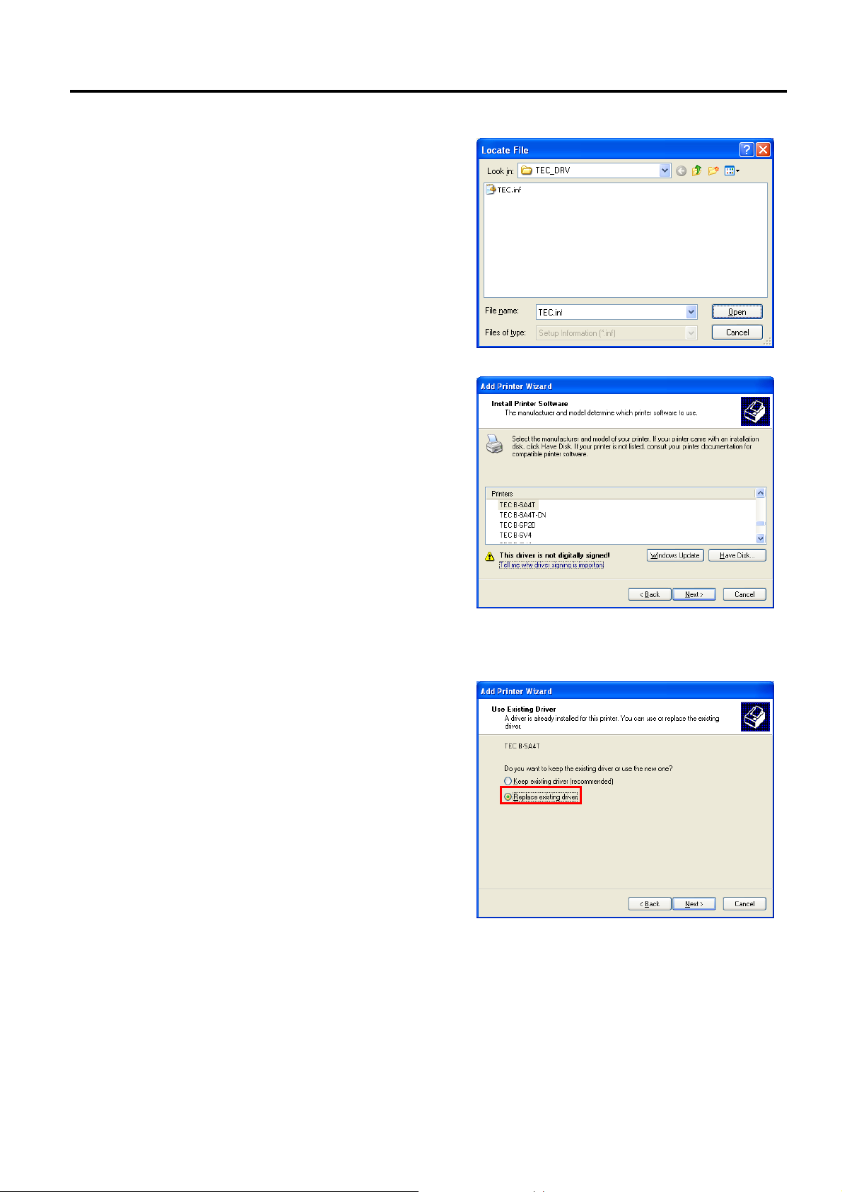
2. PRINTER SETUP ENGLISH VERSION EO1-33089
(8) Specify the printer driver install folder
(C:/TEC_DRV) created in Section 2.7.4
Preparation for Installation, and click the [Open]
button. Select the “TEC.inf” and click the [OK]
button.
(9) The list of the installable printer is displayed.
(10) Select the model to be installed, and click the [Next] button.
(Example: B-SA4T)
(11) Select the “Replace existing driver”, and click the
[Next] button.
2.7 Installing the Printer Drivers
Supplement: This step will be omitted when the
printer driver is installed for the
first time.
E2-45
Page 60

2. PRINTER SETUP ENGLISH VERSION EO1-33089
(12) Select whether or not to use the printer as a default
printer, then click the [Next] button.
(13) Select whether or not to share the printer with
other users on the network, then click the [Next]
button.
2.7 Installing the Printer Drivers
(14) Select whether or not to perform a print test, then
click the [Next] button.
E2-46
Page 61

2. PRINTER SETUP ENGLISH VERSION EO1-33089
(15) When the “Completing the Add Printer Wizard” is
displayed, click the [Finish] button.
(16) When the screen on the right appears, click the
[Continue Anyway] button.
Note: “Digital Signature Not Found” message
may be displayed. In that case, click the
[Yes] button.
2.7 Installing the Printer Drivers
(17) Installation of the printer driver starts.
(18) When the installation is completed, a new printer icon will be added to the “Printer” folder.
E2-47
Page 62

2. PRINTER SETUP ENGLISH VERSION EO1-33089
2.7 Installing the Printer Drivers
2.7.6 Installation under Windows Vista/Server2008/7/Server2008R2
(1) Turn on the PC.
Note: Log on as the user with administrative privilege.
(2) Select “Start”, “Control Panel”, “Hardware and Sound”, and “Printer” to open the printer folder.
Supplement: Entering “Printer” in the Search box of the Start menu causes the “Printer” to be shown in
the Program.
(3) Click the “Install a Printer” to start adding a printer.
(4) Select the “Add a local printer”.
(5) Select a printer port, and click the [Next] button.
E2-48
Page 63

2. PRINTER SETUP ENGLISH VERSION EO1-33089
(6) When the screen on the right appears, select
“TEC” from the Manufacturer list.
(7) The list of the installable printer models are
displayed.
2.7 Installing the Printer Drivers
(8) Select a model to be installed, then click the [Next] button.
(9) Select the “Replace the current driver”, and click
the [Next] button.
Supplement: This step will be omitted when the
printer driver is installed for the first
time.
E2-49
Page 64

2. PRINTER SETUP ENGLISH VERSION EO1-33089
(10) Select whether or not to use the printer as a default
printer, then click the [Next] button.
(11) Installation starts.
(12) When the installation is completed, the “Add
Printer” screen is displayed. At this time, a new
printer icon is added to the “Printer” folder. Click
the [Finish] button.
If you want to perform a print test, click the [Print
a test page] button.
2.7 Installing the Printer Drivers
E2-50
Page 65

2. PRINTER SETUP ENGLISH VERSION EO1-33089
2.7 Installing the Printer Drivers
2.7.7 Installation under Windows 2000 (USB with Plug & Play Enabled)
(1) Turn on the PC.
Note: Log on as the user with administrative privilege.
(2) Turn on the printer and connect it to the PC with a USB cable.
(3) “USB DEVICE” is detected and “USB Print support” is automatically installed.
(4) After a while, the “Found New Hardware Wizard”
is displayed. Click the [Next] button.
(5) Select the “Search for a suitable driver for my
device (recommended)”, and click the [Next]
button.
(6) Check the “Specify a location” checkbox, then
click the [Next] button.
E2-51
Page 66

2. PRINTER SETUP ENGLISH VERSION EO1-33089
(7) Click the [Browse] button. Specify the folder
(C:\TEC_DRV) created in Section 2.7.4, and click
the [Next] button.
(8) Make sure the driver of this device has been
detected, then click the [Next] button.
2.7 Installing the Printer Drivers
(9) When the screen on the right is displayed, click the
[Yes] button.
(10) When the “Completing the Found New
Hardware Wizard” is displayed, click the
[Finish] button.
(11) When the installation is completed, a new printer icon is added to the Printer folder.
E2-52
Page 67

2. PRINTER SETUP ENGLISH VERSION EO1-33089
2.7 Installing the Printer Drivers
2.7.8 Installation under Windows XP/Server2003 (USB with Plug & Play enabled)
(1) Turn on the PC.
Note: Log on as the user with administrative privilege.
(2) Turn on the printer, and connect it to the PC with a USB cable.
(3) “USB DEVICE” is detected, and the “USB Print Support” is automatically installed.
(4) After a while, new devices are detected.
(5) When the “Found New Hardware Wizard” is
displayed, select “Install from a list or specific
location [Advanced]” and click the [Next] button.
(6) Select the “Search for the best driver in these
locations”, check the “Include this location in the
search” checkbox, and click the [Browse] button.
Specify the folder (C:\TEC_DRV) created in
Section 2.7.4, and click the [Next] button.
(7) When the screen on the right appears, click the
[Continue Anyway] button.
E2-53
Page 68

2. PRINTER SETUP ENGLISH VERSION EO1-33089
2.7 Installing the Printer Drivers
(8) When the “Completing the Found New Hardware
Wizard” is displayed, click the [Finish] button.
(9) When the installation is completed, a new printer icon is added to the Printer folder.
2.7.9 Installation under Windows Vista/Server 2008/7/Server2008R2 (USB with Plug & Play Enabled)
(1) Turn on the PC.
Note: Log on as the user with administrative privilege.
(2) Turn on the printer and connect it to the PC with a USB cable.
(3) Installation of the device driver software is automatically started.
(4) After a while, the printer driver installation is completed.
(5) When the installation is completed, a new printer icon is added to the Printer folder.
E2-54
Page 69

2. PRINTER SETUP ENGLISH VERSION EO1-33089
2.7 Installing the Printer Drivers
2.7.10 Uninstalling the Printer Driver
1) To delete the printer drivers except for V6.5 Build75 and V6.5 Build77
In the following cases, be sure to uninstall the printer driver using the procedure below.
• When the same version is installed again.
• When an older version has been already installed.
• When the installation is canceled on the way or when the [No] is selected at a confirmation of the digital
signature.
• When the printer driver cannot be installed for some reason.
Notes: 1. When installing the printer driver with Plug & Play enabled, turn OFF the printer first.
2 When the printer driver is deleted, the information of the registered stocks and bar codes are also
deleted. This information can be saved in a file beforehand by using the export function, and
restored by using the import function after re-installation of the printer driver.
z Deleting the printer drivers except for V7.2 M-2
Before deleting the printer driver except for V7.2 M-2, follow the procedure described in Section 2.7.4
Preparation for Installation. Doing this causes the previously installed printer driver to be updated and
creates the shortcut of the Driver Wizard in the TPCL Printer Driver of TOSHIBA TEC folder.
However, it is not possible to update the printer driver which is older than V6.9.3 M-0. For such versions,
first delete “C:\TEC_DRV” folder, then conduct the Preparation for Installation. When the preparation is
completed, the shortcut of the “Driver Wizard” is created in the TPCL Printer Driver folder.
z How to uninstall the printer driver
(1) Select the “Start”, “All programs”, “TOSHIBA
TEC”, “TPCL Printer Driver”, and “Driver
Wizard”.
Note: Log on as the user with administrative
privilege.
Exit the all Windows applications before
performing the above operation. Confirm
that there is no print job in the spooler, then
close the spooler and the printer folder.
In the case of Windows Vista/Server
2008/7/Server2008R2, the User Account Control
screen may appear. In that case, click the [Allow].
(2) Select the “Remove printer drivers”, and click
the [Next] button.
E2-55
Page 70

2. PRINTER SETUP ENGLISH VERSION EO1-33089
(3) Select the “Automatically remove all TEC
Printer Drivers”, and click the [Next] button.
(4) Click the [Finish] button to start to delete the
printer drivers.
2.7 Installing the Printer Drivers
(5) When the “Restart System” screen is displayed,
click the [Restart] button.
(6) When the printer driver is deleted successfully, the
screen on the right is displayed.
Note: If the deletion of the printer driver failed,
retry from Steps 1 to 5 until the deletion
succeeds.
Note: In the case a network printer has been installed in multiple user accounts under Windows
E2-56
Page 71

2. PRINTER SETUP ENGLISH VERSION EO1-33089
2.7 Installing the Printer Drivers
Vista/server 2008/7/Server2008R2, it is not possible to delete the printer driver. First, delete the
printer icon from each user account, then delete the printer driver.
z Deleting the setup information configured during the preparation
(1) Select the “Start”, “Control Panel”, and “Add/Remove Programs”.
Note: Log on as the user with administrative privilege.
(2) Select the “TPCL Printer Driver Vx.x (version)” or “TEC Printer Driver Install file” from the list, then
click the [Delete] button.
(3) When the confirmation message is displayed, click the [Yes] button.
(4) When the “Uninstall completed” screen appears, click the [Finish] button.
2) To delete the V6.5 Build75 or V6.5 Build77
(1) Select the “Start”, “Control Panel”, and “Add/Remove Programs”.
Note: Log on as the user with administrative privilege.
(2) Select the “TEC **** printer” from the “Edit/Remove Programs”, and click the [Add and delete].
(**** indicates a printer model name. For example, B-SA4T, etc.)
(3) Confirm that the selected file in the “File Delete confirmation” window is correct, then click the [Yes]
button.
(4) When “Uninstall completed” is displayed, click the [OK] button.
Note: If you deleted the printer icon without performing Steps 1 to 4 above, delete the setup information
through the “Add/Remove Programs” after re-installing the printer driver.
(5) When the deletion is completed, reboot the PC.
E2-57
Page 72

2. PRINTER SETUP ENGLISH VERSION EO1-33089
r
p
2.8 Print Test
2.8 Print Test
After your operating environment has been set, perform a print test.
1. Perform a print test by using the Printer Driver or an Issue Command.
The printer driver’s Properties screen allows you to set the
communication conditions, media size, and other printing conditions
in accordance with your operating environment. For details, refer to
the Help for the Windows Printer Drivers screen.
Example: Stock tab display of the Printer Driver’s Properties Screen
Print Method
Senso
Label Ga
Issue Mode
Post-print Action
(Cut)
Print Speed
Fine Adjustment
Print Method: Direct thermal or thermal transfer is selectable.
Sensor: Media sensor type is selectable.
Issue Mode: Batch, strip or cut is selectable.
Post-print Action: Whether to use the cutter or not is selectable.
Fine Adjustment: Adjustment values for the feed amount, cut/strip
2. Confirm the print test result.
• When a print start position, cut/strip position, or print tone needs to
be adjusted: ⇒ Section 2.9 Position and Print Tone Fine
Adjustment
• When pre-printed media is used, and if a print start position is not
properly detected: ⇒ Section 2.10 Threshold Setting
position, etc. can be set.
E2-58
Page 73

2. PRINTER SETUP ENGLISH VERSION EO1-33089
2.8 Print Test (Cont.)
2.8 Print Test
When using a Strip Module or an optional Cutter Module
It is necessary to set the issue mode, cut/strip position, etc. on the Printer
Driver or with TPCL (TEC Printer Command Language) in accordance
with your printing condition.
For details of the TPCL, refer to the B-EX4T/EX6T Series External
Equipment Interface Specification.
Regarding how to use the Printer Driver, refer to the Help for the
Windows Printer Drivers screen.
To gain maximum performance and life from the Cutter Module or Strip
Module, periodic cleaning is required.
Before starting a cleaning, be sure to TURN OFF the printer to avoid risk
of injury.
For details of cleaning, refer to Section 4.1.3 Optional Cutter Module.
E2-59
Page 74

2. PRINTER SETUP ENGLISH VERSION EO1-33089
t
2.9 Position and Print
Tone Fine
Adjustment
Power OFF
2.9.1 Fine Adjustment
Hold down [MODE]
USER SYSTEM MODE
<1>RESET
<2>PARAMETER SET
<3>ADJUST SET
<4>LAN/WLAN
Power ON
ONLINE Mode
This section describes how to fine adjust a print start position, cut/strip
position, reverse feed amount, print tone, and ribbon motor torque.
When a fine adjustment is required, follow the procedure below.
[PAUSE]
PAUSE state
Hold down [RESTART]
User System Mode
Contents of the Fine Adjustment Menu
Menu Parameter
Adjust set
BACK ADJ. Adjusts the reverse feed amount.
X ADJUST Adjusts the print position in X
TONE ADJ. (TRANS.) Adjusts the print tone for thermal
TONE ADJ. (DIRECT) Adjusts the print tone for direct
RBN ADJ. <FW> Adjusts the ribbon take-up motor
RBN ADJ. <BK> Adjusts the ribbon feed motor
THRESHOLD <REFL.> Sets a fine adjustment value for the
THRESHOLD <TRANS.> Sets a fine adjustment value for the
The printer driver’s properties screen also has Parameter Fine Adjustmen
menu.
2.9 Position and Print Tone Fine Adjustment
• Reset
• Parameter setting (⇒Section 2.6.2)
• Fine adjustment (⇒Section 2.9)
• LAN/WLAN (⇒Section 2.6.3)
• BASIC (⇒Section 2.6.4)
• Z-MODE (⇒Section 2.6.5)
• AUTO calibration (⇒Section 2.6.6)
• Dump mode (⇒Section 2.6.7)
• Log (⇒Section 2.6.8)
FEED ADJ. Adjusts the feed amount to the
print start position
CUT ADJ. Adjusts the cut or strip position.
coordinate (horizontal direction)
transfer printing.
thermal printing.
drive voltage.
drive voltage.
threshold for the reflective sensor.
threshold for the transmissive
sensor.
NOTE:
E2-60
Page 75

2. PRINTER SETUP ENGLISH VERSION EO1-33089
3
2.9.1 Fine Adjustment(Cont.)
(1) FEED ADJ.
Print start position is shifted by fine adjusting the feed amount.
• Example of Print Start Position Fine Adjustment
When setting +3.0 mm
Compared with “+0.0mm” position, the print start
position is shifted forward.
When setting +0.0 mm
When setting –3.0 mm
Compared with “+0.0mm” position, the print start
position is shifted backward.
50.0mm
49.9mm
-49.9mm
-50.0mm
Feed Direction
Feed Direction
2.9 Position and Print Tone Fine Adjustment
One label
Print Start Position
mm
One label
Print Start Position
3mm
Feed Direction
One label
Print Start Position
E2-61
Page 76

2. PRINTER SETUP ENGLISH VERSION EO1-33089
3
3
Label
Print Head
Backi
2.9.1 Fine Adjustment(Cont.)
• Example of Cut Position Fine Adjustment
When setting +3.0 mm
Compared with “+0.0mm” position, the cut position
is shifted forward.
When setting +0.0 mm
When setting –3.0 mm
Compared with “+0.0mm” position, the cut position
is shifted backward.
(2) CUT ADJ.
Cut position or peel-off position is shifted by fine adjusting the feed
amount.
• Example of Peel-off Position Fine Adjustment
When setting +3.0 mm
Compared with “+0.0mm” position, the peel-off
position is shifted forward.
When setting +0.0 mm
When setting –3.0 mm
Compared with “+0.0mm” position, the peel-off
position is shifted backward.
50.0mm
49.9mm
-49.9mm
-50.0mm
Feed Direction
Feed Direction
Feed Direction
Feed Direction
2.9 Position and Print Tone Fine Adjustment
mm
Cut Position
Cut Position
mm
Cut Position
Platen
Strip Plate
ng Paper
E2-62
Page 77
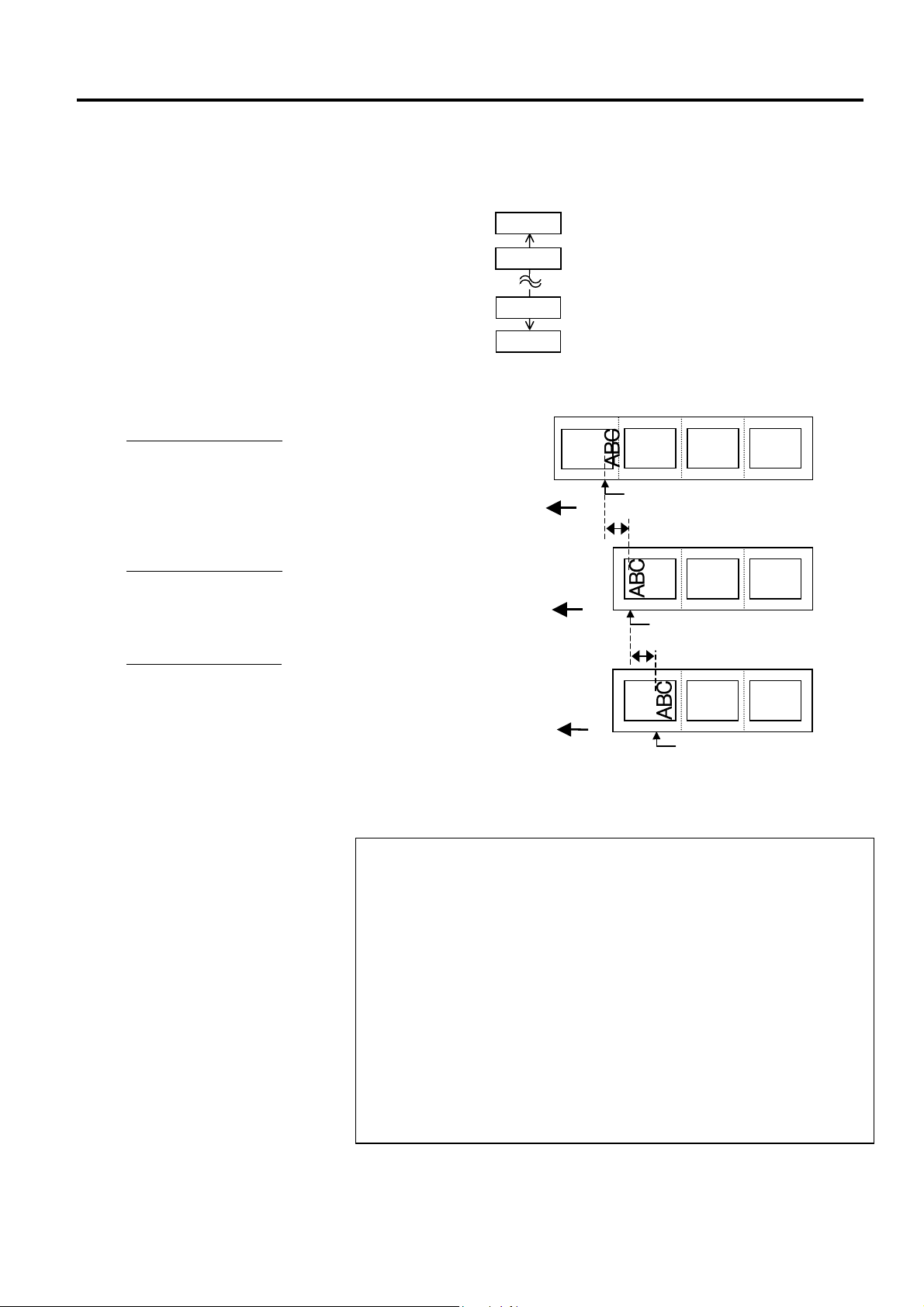
2. PRINTER SETUP ENGLISH VERSION EO1-33089
D
p
p
2.9.1 Fine Adjustment(Cont.)
(3) BACK ADJ.
Reverse feed amount to the next print start position is fine adjusted.
• Example of Reverse Feed Amount Fine Adjustment
When setting +3.0 mm
Compared with “+0.0mm” position, the print start position
after a reverse feed is shifted forward.
When setting +0.0 mm
When setting –3.0 mm
Compared with “+0.0mm” position, the print start position
after a reverse feed is shifted backward.
epending on the print conditions, a label may not return to the home
osition with a reverse feed, even if a reverse feed amount is specified to
the same length as the forward feed.
On the following conditions, the media may not return to the home
osition, resulting in an error.
• The media sensor is used.
• The media pitch is almost the same as the distance between the print
head and the media sensors (75.5 mm.)
• A printer action includes a reverse feed (such as cut issues, strip issues,
and automatic forward feed standby.)
To prevent an error from occurring, the reverse feed amount needs to be
increased by performing the back feed fine adjustment in the positive (+)
direction.
9.9mm
9.8mm
-9.8mm
-9.9mm
Feed Direction
Feed Direction
Feed Direction
2.9 Position and Print Tone Fine Adjustment
Print Start Position after a
reverse feed
3mm
Print Start Position after a
3mm
reverse feed
Print Start Position after a
reverse feed
NOTE:
E2-63
Page 78
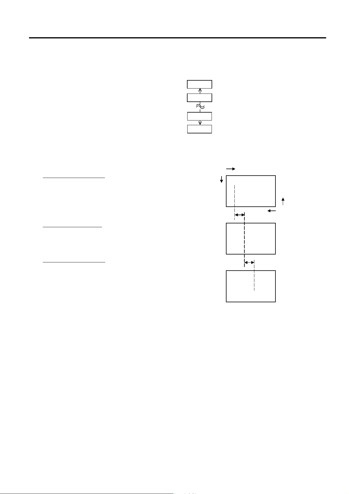
2. PRINTER SETUP ENGLISH VERSION EO1-33089
Y
2.9.1 Fine Adjustment(Cont.)
(4) X ADJUST
Print position in X-coordinate (horizontal direction) is fine adjusted.
• Example of X Coordinate Fine Adjustment
When setting –50.0 mm
Compared with “+0.0mm” position, the print position
is shifted to the left.
When setting +0.0 mm
When setting +50.0 mm
Compared with “+0.0mm” position, the print position
is shifted to the right.
99.5mm
99.4mm
-99.4mm
-99.5mm
Top Down Printing
Y
50.0mm
2.9 Position and Print Tone Fine Adjustment
X
ABC
Bottom First Printing
X
ABC
50.0mm
ABC
E2-64
Page 79
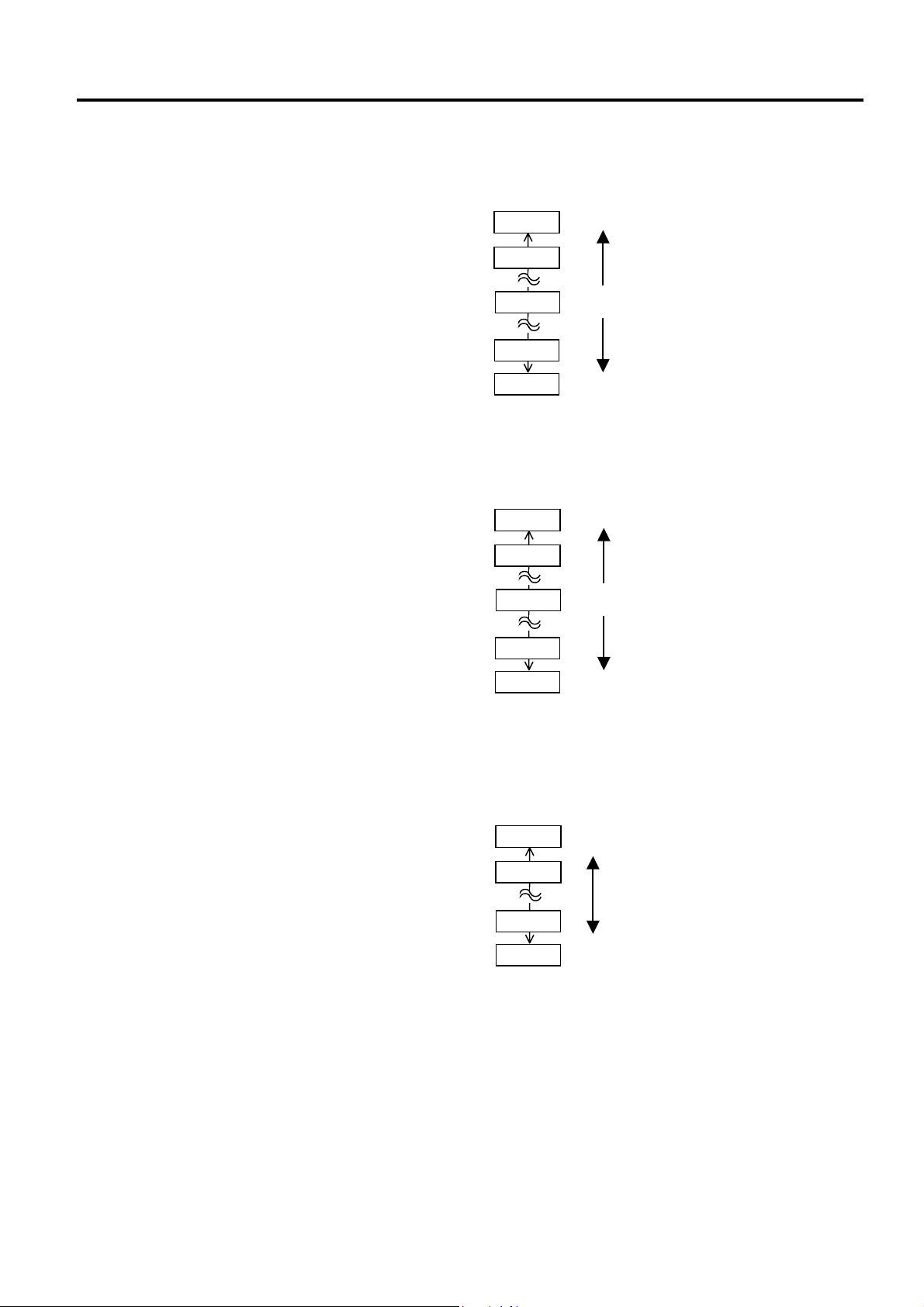
2. PRINTER SETUP ENGLISH VERSION EO1-33089
2.9.1 Fine Adjustment(Cont.)
2.9 Position and Print Tone Fine Adjustment
(5) TONE ADJ.(TRANS.)
Print tone for the thermal transfer printing is fine adjusted.
+10
Darker
+9
+0
Standard
-19
-20
Lighter
(6) TONE ADJ.(DIRECT.)
Print tone for the direct thermal printing is fine adjusted.
+10
Darker
+9
+0
Standard
-19
-20
Lighter
(7) RBN ADJ.<FW>
When the ribbon is slack or wrinkled and printing is affected, fine
adjust the ribbon motor torque.
+10
+9
-14
High
Motor torque
-15
Low
E2-65
Page 80

2. PRINTER SETUP ENGLISH VERSION EO1-33089
p
p
2.9.1 Fine Adjustment (Cont.)
When “0.0 V” is se for this
arameter, it is automatically
corrected to 1.0V (default)
after the power is turned OFF
then ON.
NOTE:
2.9 Position and Print Tone Fine Adjustment
(8) RBN ADJ.<BK>
When the ribbon is slack or wrinkled and printing is affected, fine
adjust the ribbon motor torque.
+10
+9
-14
High
Motor torque
-15
Low
(9) THRESHOLD <REFL.>
When you perform a threshold setting for the reflective sensor and found
the threshold needs to be adjusted, set a fine adjustment value.
This menu is accessible directly from the Threshold Setting Mode so that
the threshold can be manually set right away.
Manually set threshold = Peak voltage – The value set here
For details, refer to Section 2.10.
4.0V
3.9V
0.1V
0.0V
NOTE:
When “0.0 V” is se for this
arameter, it is automatically
corrected to 1.4V (default)
after the power is turned OFF
then ON.
(10) THRESHOLD <TRANS.>
When you perform a threshold setting for the Transmissive sensor and
found the threshold needs to be adjusted, set a fine adjustment value.
This menu is accessible directly from the Threshold Setting Mode so that
the threshold can be manually set right away. .
Manually set threshold = Peak voltage – The value set here
For details, refer to Section 2.10.
4.0V
3.9V
0.1V
0.0V
E2-66
Page 81

2.PRINTER SETUP ENGLISH VERSION EO1-33089
2.10 Threshold Setting
Power OFF
Power ON
ONLINE Mode
Threshold Setting Mode
2.10 Threshold Setting
To maintain a constant print position the printer uses the media sensor to
detect a print start position according to the difference of voltage between
a print area and a gap or black mark. When the media is pre-printed, the
darker (or more dense) inks can interfere with this process causing paper
jam errors.
To get around this problem, first, try an automatic threshold setting.
If the problem still occurs, then, the threshold voltage needs to be fine
adjusted.
Threshold is a voltage level by which the printer determines whether a
print area or a gap/a black mark is being detected by the media sensor.
The threshold is a boundary between a print area and a gap/black mark,
and should be a midpoint of their voltage levels.
[PAUSE]
PAUSE state
Hold down [PAUSE]
• Reflective sensor
• Transmissive sensor
(1) Load the media to be used.
(2) Choose 1) or 2) depending on the sensor type to be used, then press
the [ENTER].
NOTES:
1. Failure to feed more than 1.5
labels may result in an
incorrect threshold setting.
2. A paper end or ribbon end
error cannot be detected
during paper feed.
(3) Hold down the [PAUSE] until more than 1.5 labels (tags) have been
fed.
The media will continue to be fed until the [PAUSE] is released. (An
automatic threshold setting for the selected sensor is completed by
this operation.)
(4) The result of the threshold setting is displayed.
(e.g.: Succeeded) (e.g: Failed)
Sensor type
Result (Text)
Result (Graph)
Key operation guide
E2-67
Page 82

2.PRINTER SETUP ENGLISH VERSION EO1-33089
R
I
P
F
2.10 Threshold Setting
(Cont.)
To make a threshold value set
in this section effective, select
the Transmissive Sensor (when
using pre-printed media) or
eflective Sensor (when using
manual threshold value) in
ssue Command or the printer
driver.
NOTE:
NOTE:
The threshold can be manually
set as follows:
Manually set threshold =
eak voltage – Threshold fine
adjustment value
e.g.) When Peak=3.5V and
ine adjustment value=1.0V,
the threshold will be set to
2.5V.
2.10 Threshold Setting
Display example Explanation
1
2
3
4
5
6
Result: OK (Mid.)
Threshold is at the midpoint between the
peak and the baseline.
Result: OK (High)
Threshold is near the peak voltage.
Adjusting the threshold to the midpoint
between the peak and the baseline enables
more accurate detection.
Result: OK (Low)
Threshold is near the baseline voltage.
Adjusting the threshold to the midpoint
between the peak and the baseline enables
more accurate detection.
Failed (1)
The media sensor cannot detect a gap/black
mark. Sensor adjustment is required.
(⇒Section 2.11)
Failed (1)
The media sensor cannot detect a gap/black
mark. (Threshold ≤ Baseline) Sensor
adjustment is required. (⇒Section 2.11)
Failed (2)
Detection by the media sensor is disabled.
Sensor adjustment is required. (⇒Section
2.11)
(5) Press the [RIGHT] to see the details.
Sensor type
Peak voltage
Threshold voltage
Baseline voltage
Key operation guide
(e.g: Succeeded) (e.g.: Failed)
(6) To return to the previous display, press the [LEFT].
To adjust the threshold, press the [RIGHT]. The threshold fine
adjustment screen in ADJUST SET menu appears.
Set a value and press the [ENTER].
(7) The result after manually setting the threshold is displayed.
E2-68
Page 83

2.PRINTER SETUP ENGLISH VERSION EO1-33089
2.11 Sensor Setting
SYSTEM MODE
<2>PARAMETER SET
<3>ADJUST SET
<4>TEST PRINT
<5>SENSOR ADJUST
Turn on the power while holding down
[FEED] & [PAUSE] or [MODE].
If a paper jam error still occurs even after a threshold setting has been
performed, register the voltage level of media to the media sensor.
Power OFF
System Mode
Contents of the Sensor Adjust Menu
Menu Parameter
Sensor
Adjust
TRANS. Registers the voltage level of label gap to
PE REFL./TRANS. Registers the voltage level of no paper to
RIBBON Registers the voltage level of ribbon to the
2.11 Sensor Setting
• Self diagnosis
• Parameter setting
• Fine adjustment
• Test print
• Sensor adjustment
• RAM clear
• Interface setting
• BASIC mode
• RFID setting
• Real Time Clock
• Z-MODE
• USB memory
• Reset
TEMPERATURE Displays the ambient temperature and
print head temperature.
REFLECT Registers the voltage level of tag paper’s
print area to the reflective sensor.
the transmissive sensor.
the reflective/transmissive sensor.
ribbon end sensor.
E2-69
Page 84

2.PRINTER SETUP ENGLISH VERSION EO1-33089
2.11 Sensor Setting
(Cont.)
2.11 Sensor Setting
(1) REFLECT
1. Select “REFLECT” from the Sensor Adjust menu.
2. Place the tag paper to be used on the reflective sensor so that the
sensor can detect a print area.
3. Hold down the [ENTER] for 3 seconds or more.
4. When registration of the “print area level” is completed, “Adjust
Complete” is displayed and an asterisk is shown on the right side
of the voltage.
(2) TRANS.
1. Select “TRANS.” from the Sensor Adjust menu.
2. Remove some labels and place the backing paper so that the
Transmissive sensor can detect it.
3. Hold down the [ENTER] for 3 seconds or more.
4. When registration of the “label gap level” is completed, “Adjust
Complete” is displayed and an asterisk is shown on the right side
of the voltage.
(3) PE REFL./TRANS.
1. Select “PE REFL./TRANS.” from the Sensor Adjust menu.
2. Remove any media from the media sensor.
3. Hold down the [ENTER] for 3 seconds or more.
4. When registration of the “no media level” is completed, “Adjust
Complete” is displayed and an asterisk is shown on the right side
of the voltage.
E2-70
Page 85

3. ON LINE MODE ENGLISH VERSION EO1-33089
3. ON LINE MODE
3.1 Key Functions
FEED
MODE
LEFT
CANCEL
DOWN
PAUSE
RESTART
UP
RIGHT
ENTER
3.1 Key Functions
This chapter describes usage of the keys on the Operation Panel in On
Line mode.
When the printer is in On Line mode and connected to a host computer,
the normal operation of printing images on labels or tags can be
accomplished.
Key functions in the online mode
Key Function
[FEED]
[RESTART]
[PAUSE]
[UP] (1) Scrolls up
[DOWN] (1) Scrolls down
[LEFT] (1) Displays previous help message page.
[RIGHT] (1) Displays next help message page.
(1) Feeds one piece of paper.
(2) Prints the data in the image buffer on one label
according to the system mode setting.
(3) Closes the help message.
(1) Resumes printing after a temporary stop of label
printing or after an error.
(2) Places the printer in the usual initial state which
is obtained when the power is turned on.
(3) Places the printer in the user system mode.
(4) Closes the help message.
(1) Stops label printing temporarily.
(2) Programs the threshold values.
(3) Closes the help message.
(1) Places the printer in the user system mode. [MODE]
(2) Closes the help message.
(1) Clears the job. [CANCEL]
(2) Displays previous help message page.
(1) Displays next help message page. [ENTER]
(2) Closes the help message.
E3- 1
Page 86

3. ON LINE MODE ENGLISH VERSION EO1-33089
3.2 LCD
3.2 LCD
Online state
(1)
(2)
(3)
(4)
(6)
(5)
(7)
(8)
(9)
Error state
(10)
(11)
(12)
No. Description
(1) Model name and firmware version
(2) Message
(3) The number of labels printed
(4) IP address (only when LAN/WLAN is enabled.)
(5) Radio intensity (only when WLAN is enabled.)
Indicates the radio intensity in 4 levels.
(6) WLAN connection (only when WLAN is enabled.)
▪ Lights up when connecting to an access point.
▪ Flashes while roaming.
▪ Goes off when disconnected.
(7) Data transmission
Appears while receiving data from the host.
(8) RFID (only when RFID module is installed.)
▪ Appears when a communication between the printer and the
RFID module is enabled.
▪ Flashes while communicating with the RFID module.
(9) Ribbon near end
Flashes when a ribbon near end state is detected.
(10) The number of remaining labels to print
(11) Error description and solution
(12) Help guide
Appears when a help guide message is provided. Press the
[RIGHT] key to see the help guide message.
E3- 2
Page 87

3. ON LINE MODE ENGLISH VERSION EO1-33089
p
y
3.3 Operation Example
3.3 Operation Example
Online Mode
Idling or normal issuing
When [PAUSE] key is
pressed while printing:
When [RESTART] key is pressed,
the printer resumes printing if there
is remaining data.
Printing is stopped.
If the print head is
opened during idling:
Help guide is displayed.
Press [RIGHT] ke
If an error occurs
while
rinting:
Printing is stopped and
Help guide is displayed.
Close the print head.
Help guide message for head open
Load media.
When [RESTART] key is pressed, the
printer resumes printing if there is
remaining data.
Press [RIGHT] key
Help guide message for no paper
E3- 3
Page 88

3. ON LINE MODE ENGLISH VERSION EO1-33089
p
3.3 Operation Example
3.3 Operation Example (Cont.)
Help Guide Message
Idling or normal issuing
If an error occurs
while
rinting:
Printing is stopped and
Help guide is displayed.
[RIGHT] or [ENTER]
[LEFT] or
[CANCEL]
[LEFT] or
[CANCEL]
Load media.
When [RESTART] key is pressed, the
printer resumes printing if there is
remaining data.
Cause of the error
[RIGHT] or
[ENTER]
Troubleshooting
[RIGHT] or
[ENTER]
How to restore to online
[RIGHT] or
[ENTER]
E3- 4
Page 89

3. ON LINE MODE ENGLISH VERSION EO1-33089
(
)
3.3 Operation Example
3.3 Operation Example (Cont.)
Cancellation of Print Job
While [CANCEL] is held down, the received data is discarded.
Quick reset
Idling or normal issuing
When [PAUSE] key is
pressed while printing:
If an error occurs while
printing:
Hold down [CANCEL] for 3 sec. or more.
Hold down [CANCEL] for 3 sec. or more.
E3- 5
Page 90

4. MAINTENANCE ENGLISH VERSION EO1-33089
4. MAINTENANCE
1. Be sure to disconnect the
2. To avoid injury, be careful
3. The print head becomes
4. Do not pour water directly
4.1 Cleaning
4.1.1 Print Head/Platen/ Sensors
1. Do not use any volatile
2. Do not touch the Print
WARNING!
power cord before
performing maintenance.
Failure to do this may
cause an electric shock.
not to pinch your fingers
while opening or closing
the cover and print head
block.
hot immediately after
printing. Allow it to cool
before performing any
maintenance.
onto the printer.
CAUTION!
solvent including thinner
and benzene, as this may
cause discoloration to the
cover, print failure, or
breakdown of the printer.
Head Element with bare
hands, as static may
damage the Print Head.
4.1 Cleaning
This chapter describes how to perform routine maintenance.
To ensure the continuous high quality operation of the printer, you should
perform a regular maintenance routine. For high throughput it should be
done on a daily basis. For low throughput it should be done on a weekly
basis.
To maintain the printer performance and print quality, please clean the
printer regularly, or whenever the media or ribbon is replaced.
1. Turn off the power and unplug the printer.
2. Open the Top Cover.
3. Turn the Head Lever to Free position, then release the Ribbon Shaft
Holder Plate.
4. Open the Print Head Block.
5. Remove the ribbon and media.
CAUTION!
When cleaning the print head, be careful not to damage the print head
with a hard object like a watch or a ring.
Care must be taken not to allow
the metal or glass part of a watch
to touch the print head edge.
Since the print head element can be easily damaged by shock, please
treat it carefully by not hitting a hard object against it.
E4- 1
Care must be taken not to allow a
metal object like a ring to touch
the print head edge.
Page 91

4. MAINTENANCE ENGLISH VERSION EO1-33089
P
p
r
4.1.1 Print Head/Platen/
Sensors (Cont.)
lease purchase the Print Head
Cleaner from your authorised
TOSHIBA TEC service
representative.
NOTE:
4.1.2 Covers and Panels
1. DO NOT POUR WATER
directly onto the printer.
2. DO NOT APPLY cleaner
or detergent directly onto
any cover or panel.
3. NEVER USE THINNER
OR OTHER VOLATILE
SOLVENT on the plastic
covers.
4. DO NOT clean the panel,
covers, or the supply
window with alcohol as it
may cause them to
discolour, loose their
shape or develop
structural weakness.
CAUTION!
4.1 Cleaning
6. Clean the Print Head Element with a Print Head Cleaner or a cotton
swab or soft cloth slightly moistened with alcohol.
Print Head
Print Head
Element
7. Wipe the Platen, Feed Roller, and Pinch Roller with a soft cloth
8. Wipe the Feed Gap Sensor and Black Mark Sensor with a dry soft
Wipe the covers and panels with a dry soft cloth or a cloth slightly
moistened with mild detergent solution.
Platen
Black Mark Sensor/
Feed Ga
slightly moistened with alcohol. Remove dust or foreign substances
from the internal part of the printer.
cloth.
Senso
Pinch Roller
Feed Roller
E4- 2
Page 92

4. MAINTENANCE ENGLISH VERSION EO1-33089
4.1.3 Optional Cutter Module
1. Be sure to turn the power
off before cleaning the
Cutter Module.
2. As the cutter blade is
sharp, care should be
taken not to injure yourself
while cleaning.
WARNING!
4.1 Cleaning
The disc cutter and rotary cutter are available as an option. They are both
cleaned in the same way. When removing the Cutter Cover of the rotary
cutter unit, remove the screws from the bottom of the cover.
1. Loosen the two Plastic Head Screws to remove the Cutter Cover.
2. Remove the jammed paper.
3. Clean the Cutter with a soft cloth slightly moistened with alcohol.
4. Attach the Cutter Cover.
Plastic Head Screw
Cutter Unit
E4- 3
Page 93

5. TROUBLESHOOTING ENGLISH VERSION EO1-33089
N
p
5.1 Error Messages
5. TROUBLESHOOTING
This chapter lists the error messages, possible problems, and their solutions.
If a problem cannot be solved by taking the actions described in this chapter, do not attempt to repair the
rinter. Turn off and unplug the printer, then contact an authorised TOSHIBA TEC service representative
for assistance.
5.1 Error Messages
OTES:
• If an error is not cleared by pressing the [RESTART] key, turn the printer off and then on.
• After the printer is turned off, all print data in the printer is cleared.
• “****” indicates the number of unprinted media. Up to 9999 (in pieces).
Error Messages Problems/Causes Solutions
HEAD OPEN The Print Head Block is opened in
Online mode.
HEAD OPEN **** Feeding or printing has been attempted
with the Print Head Block open.
COMMS ERROR A communication error has occurred. Make sure the interface cable is correctly
PAPER JAM ****
1. The media is jammed in the media
path. The media is not fed smoothly.
2. The media is not loaded properly.
WARNING!
Close the Print Head Block.
Close the Print Head Block. Then press
the [RESTART] key.
connected to the printer and the host, and
the host is turned on.
Remove the jammed media, and clean
1.
the Platen. Then reload the media
correctly. Finally press the
[RESTART] key.
⇒ Section 5.3.
2. Reload the media correctly. Then
press the [RESTART] key.
⇒ Section 2.3.
3. Wrong Media Sensor is selected for
the media being used.
4. The Black Mark Sensor is not
correctly aligned with the Black
Mark on the media.
5. Size of the loaded media is different
from the programmed size.
6. Media sensor has not been properly
calibrated for the media being used.
E5- 1
3. Turn the printer off and then on. Then
select the Media Sensor for the media
being used. Finally resend the print
job.
4.
Adjust the sensor position. Then press
the [RESTART] key.
⇒ Section 2.3.1.
Replace the loaded media with one
5.
that matches the programmed size
then press the [RESTART] key, or
turn the printer off and then on, select
a programmed size that matches the
loaded media. Finally resend the print
job.
Refer to Section 2.10 to set the
6.
threshold. If this does not solve the
problem, turn off the printer, and call a
TOSHIBA TEC authorised service
representative.
Page 94

5. TROUBLESHOOTING ENGLISH VERSION EO1-33089
5.1 Error Messages
5.1 Error Messages (Cont.)
Error Messages Problems/Cause Solutions
CUTTER ERROR ****
(Only when the cutter
module is installed on
the printer.)
NO PAPER ****
RIBBON ERROR ****
NO RIBBON **** The ribbon has run out. Load a new ribbon. Then press the
REWIND FULL **** The Built-in Rewinder Unit is full. Remove the backing paper from the Built-
EXCESS HEAD TEMP The Print Head has overheated. Turn off the printer, and allow it to cool
HEAD ERROR There is a problem with the Print Head. Replace the Print Head.
POWER FAILURE
1. The media is jammed in the cutter. 1. Remove the jammed media. Then
press the [RESTART] key. If this
does not solve the problem, turn off
the printer, and call a TOSHIBA TEC
authorised service representative.
⇒ Section 4.1.3.
2. The Cutter Cover is not attached
2. Attach the Cutter Cover properly.
properly.
1. The media has run out. 1. Load new media. Then press the
[RESTART] key.
⇒ Section 2.3.1.
2. The media is not loaded properly. 2. Reload the media correctly. Then
press the [RESTART] key.
⇒ Section 2.3.1.
3. The media sensor position has not
been adjusted properly.
3. Adjust the sensor position. Then press
the [RESTART] key.
⇒ Section 2.3.1.
4. Media sensor has not been properly
calibrated for the media being used.
4. Refer to Section 2.10 to set the
threshold. If this does not solve the
problem, turn off the printer, and call a
TOSHIBA TEC authorised service
representative.
5. The media is slack. 5. Take up any slack in the media.
1. The ribbon is not fed properly. 1. Remove the ribbon, and check the
status of the ribbon. Replace the
ribbon, if necessary. If the problem is
not solved, turn off the printer, and
call a TOSHIBA TEC authorised
service representative.
2. The ribbon is not loaded. 2. Load a ribbon.
⇒ Section 2.3.2
3. The ribbon sensor has a problem. 3. Turn off the printer and call a
TOSHIBA TEC authorised service
representative.
[RESTART] key.
⇒ Section 2.3.2.
In Rewinder Unit. Then press the
[RESTART] key.
down (about 3 minutes). If this does not
solve the problem, call a TOSHIBA TEC
authorised service representative.
A momentary power failure has
occurred.
Check the power source which supplies
power to the printer. If the rating is not
correct, or if the printer shares the same
power outlet with other electrical
appliances that consume large amounts of
power, change the outlet.
E5- 2
Page 95

5. TROUBLESHOOTING ENGLISH VERSION EO1-33089
5.1 Error Messages (Cont.)
Error Messages Problems/Cause Solutions
SYSTEM ERROR
MEMORY WRITE ERR.
FORMAT ERROR
MEMORY FULL
EEPROM ERROR
RFID WRITE ERROR
RFID ERROR
LOW BATTERY
SYNTAX ERROR
PASSWORD INVALID
Please Power OFF
Other error messages A hardware or software problem may
1. The printer is used in a location
where it is subject to noise. Or, there
are power cords of other electrical
appliances near the printer or
interface cable.
2. The Power Cord of the printer is not
grounded.
3. The printer shares the same power
source with any other electrical
appliances.
4. An application software used on
your host computer has an error or
malfunction.
An error has occurred in writing to the
flash ROM/USB memory.
An error has occurred in formatting the
flash ROM/USB memory.
Saving failed because of an insufficient
capacity of the flash ROM/USB
memory.
Data cannot be read from/written to a
backup EEPROM properly.
The printer did not succeed in writing
data onto an RFID tag after having
retried for a specified times.
The printer cannot communicate with
the RFID module.
The voltage of the Real Time Clock
Battery is low level.
While the printer is in the Download
mode for upgrading the firmware, it
receives an improper command, for
example, a Issue Command.
A wrong password was entered
consecutively for three times.
have occurred.
5.1 Error Messages
1. Keep the printer and the interface
cables away from the source of noise
2. Ground the Power Cord.
3. Provide an exclusive power source for
the printer.
4. Confirm the host computer operates
properly.
Turn the printer off, and then on again.
Turn the printer off, and then on again.
Turn the printer off, and then on again.
Turn the printer off, and then on again.
Press the [RESTART] key.
Turn the printer off, and then on again.
If you would like to keep using the same
battery even after “LOW BATTERY”
error occurs, turn off the printer and start
it in the system mode. Set the date and
time for the RTC again. Reset the printer,
then place it in online. As long as the
power is on, this date and time will be
effective.
Call a TOSHIBA TEC authorised service
representative for replacement of the
battery.
Turn the printer off, and then on again.
Please inquire of the system administrator.
Turn the printer off and then on. If this
does not solve the problem, turn off the
printer again, and call a TOSHIBA TEC
authorised service representative.
E5- 3
Page 96

5. TROUBLESHOOTING ENGLISH VERSION EO1-33089
5.2 Possible Problems
5.2 Possible Problems
This section describes problems that may occur when using the printer, and their causes and solutions.
Possible Problems Causes Solutions
The printer will not
turn on.
The media is not fed.
Pressing the [FEED]
key in the initial state
results in an error.
Nothing is printed on
the media.
The printed image is
blurred.
The cutter does not
cut.
The Strip Module does
not remove labels from
the backing paper.
1. The Power Cord is disconnected. 1. Plug in the Power Cord.
2. The AC outlet is not functioning
correctly.
3. The fuse has blown, or the circuit
2. Test with a power cord from another
electric appliance.
3. Check the fuse or breaker.
breaker has tripped.
1. The media is not loaded properly. 1. Load the media properly.
⇒ Section 2.3.1.
2. The printer is in an error condition. 2. Solve the error in the message display.
(See Section 5.1 for more detail.)
A feed or an issue was attempted not on
the following default conditions.
Sensor type: Feed gap sensor
Printing method: Thermal transfer
Media pitch: 76.2 mm
Change the print condition by using the
printer driver or a print command so that
it corresponds to your printing conditions.
Then, clear the error state by pressing the
[RESTART] key.
1. The media is not loaded properly. 1. Load the media properly.
⇒ Section 2.3.1.
2. The ribbon is not loaded properly. 2. Load the ribbon properly.
⇒ Section 2.3.2.
3. The print head is not installed
properly.
4. The combination of the ribbon and
media is not proper.
1. The combination of the ribbon and
media is not proper.
3. Install the print head properly. Close
the Print Head Block.
4. Select an appropriate ribbon for the
media type being used.
1. Select an appropriate ribbon for the
media type being used.
2. The Print Head is not clean. 2. Clean the print head using the Print
Head Cleaner or a cotton swab slightly
moistened with ethyl alcohol.
1. The Cutter Cover is not attached
1. Attach the Cutter Cover properly.
properly.
2. The media is jammed in the Cutter. 2. Remove the jammed paper.
⇒ Section 4.1.3.
3. The cutter blade is dirty. 3. Clean the cutter blade.
⇒ Section 4.1.3.
Label stock is too thin or the glue is too
sticky.
1. Refer to Section 7.1 Media and
change the label.
2. Set the Pre-strip function to ON.
⇒Section 2.6.2.
E5- 4
Page 97

5. TROUBLESHOOTING ENGLISH VERSION EO1-33089
I
5.3 Removing Jammed Media
5.3 Removing Jammed
Media
Do not use any tool that may
damage the Print Head.
CAUTION!
NOTE:
f you get frequent jams in the
cutter, contact a TOSHIBA TEC
authorised service
representative.
This section describes in detail how to remove jammed media from the
printer.
1. Turn off and unplug the printer.
2. Open the Top Cover.
3. Turn the Head Lever to Free position, then open the Ribbon Shaft
Holder Plate.
4. Open the Print Head Block.
5. Remove the ribbon and media.
Print Head Block
6. Remove the jammed media from the printer. DO NOT USE any sharp
implements or tools as these could damage the printer.
7. Clean the Print Head and Platen, then remove any further dust or
foreign substances.
8. Paper jams in the Cutter Unit can be caused by wear or residual glue
from label stock on the cutter. Do not use non-specified media in the
cutter.
When removing the jammed media, be careful not to damage the
print head with a hard object like a watch or a ring.
Ribbon Shaft Holder Plate
CAUTION!
Care must be taken not to allow
the metal or glass part of a watch
to touch the print head edge.
Since the print head element can be easily damaged by shock, please
treat it carefully by not hitting a hard object against it.
E5- 5
Care must be taken not to allow a
metal object like a ring to touch
the print head edge.
Page 98

6. PRINTER SPECIFICATIONS ENGLISH VERSION EO1-33089
6. PRINTER SPECIFICATIONS
6. PRINTER SPECIFICATIONS
This section describes the printer specifications.
Model
Item
Dimension (W x D x H) 278 mm x 460 mm x 310 mm (10.9” x 18.1” x 12.2”)
Weight (kg) 17 kg
Operating temperature range 5 degC to 40 degC (40 degF to 104 degF)
Relative humidity 25% to 85% RH (no condensation)
Power supply Universal switching power source AC 100 V to 240 V, 50/50 Hz +/- 10%
Input voltage AC100 V to 240 V, 50/60 Hz +/- 10%
Power
Consumption
Resolution 8 dots/mm (203 dpi) 12 dots/mm (305 dpi)
Printing method Thermal transfer or Thermal direct
Printing speed 76.2 mm/sec. (3 inches/sec.)
Available media width (including
backing paper)
Effective print width (max.) 104.0 mm (4.1 inches)
Issue mode Batch
LCD Message display Graphic type 128 x 64 dots
During a print job* 116W 0.59A
During stand-by 15W or less
During sleep mode 5.7W 0.09A
B-EX4T-GS12-QM-R/CN-R B-EX4T-TS12-QM-R/CN-R
76.2 mm/sec. (3 inches/sec.)
152.4 mm/sec. (6 inches/sec.)
254.0 mm/sec. (10 inches/sec.)
304.8 mm/sec. (12 inches/sec.)
355.6 mm/sec. (14 inches/sec.)
25.0 mm to 120 mm (0.98 inches to 4.72 inches)
Strip (Strip mode is enabled only when the optional Strip Module is
installed.)
Cut (Cut mode is enabled only when the optional Cutter Module is
installed.)
127.0 mm/sec. (5 inches/sec.)
203.8 mm/sec. (8 inches/sec.)
254.0 mm/sec. (10 inches/sec.)
304.8 mm/sec. (12 inches/sec.)
355.6 mm/sec. (14 inches/sec.)
*: While 20% slant lines are printed in the specified format.
E6- 1
Page 99

6. PRINTER SPECIFICATIONS ENGLISH VERSION EO1-33089
N
6. PRINTER SPECIFICATIONS
Model
B-EX4T-GS12-QM-R/CN-R B-EX4T-TS12-QM-R/CN-R
Item
Bar code types JAN8, JAN13, EAN8, EAN8+2 digits, EAN8+5 digits, EAN13, EAN13+2
digits, EAN13+5 digits, UPC-E, UPC-E+2 digits, UPC-E+5 digits, UPC-A,
UPC-A+2 digits, UPC-A+5 digits, MSI, ITF, NW-7, CODE39, CODE93,
CODE128, EAN128, Industrial 2 to 5, Customer Bar Code, POSTNET, KIX
CODE, RM4SCC (ROYAL MAIL 4 STATE CUSTOMER CODE), GS1
DataBar
Two-dimensional code Data Matrix, PDF417, QR code, Maxi Code, Micro PDF417, CP Code
Font Times Roman (6 sizes), Helvetica (6 sizes), Presentation (1 size), Letter
Gothic (1 size), Prestige Elite (2 sizes), Courier (2 sizes), OCR (2 types),
Gothic (1 size), Outline font (4 types), Price font (3 types)
24 x 24 Simp-Chinese font (only CN model)
Rotations 0, 90, 180, 270 deg
Standard interface USB interface
LAN interface
Optional interface Serial interface (B-EX700-RS-QM-R)
Parallel interface (B-EX700-CEN-QM-R)
Expansion I/O interface (B-EX700-IO-QM-R)
RTC & USB Host interface (B-EX700-RTC-QM-R)
Wireless LAN interface (B-EX700-WLAN-QM-R)
OTES:
• Data Matrix
• PDF417
TM
is a trademark of International Data Matrix Inc., U.S.
TM
is a trademark of Symbol Technologies Inc., US.
• QR Code is a trademark of DENSO CORPORATION.
• Maxi Code is a trademark of United Parcel Service of America, Inc., U.S.
E6- 2
Page 100

7. SUPPLY SPECIFICATIONS ENGLISH VERSION EO1-33089
7.1 Media
7. SUPPLY SPECIFICATIONS
7.1 Media
Please make sure that the media being used is approved by TOSHIBA TEC. The warranty does not apply when a
problem is caused by using media that is not approved by TOSHIBA TEC.
For information regarding TOSHIBA TEC approved media, please contact a TOSHIBA TEC authorised service
representative.
7.1.1 Media Type
Two types of media can be loaded for this thermal transfer and direct thermal printer: label or tag. The table
below shows size and shape of the media available for this printer.
position
Cut position
Stop
k
Label
j
B-EX4T-GS12-QM-R [Unit: mm]
Label dispensing mode
Item
c Media pitch
d Label length 8.0 – 1498.0 23.4 – 1498.0
e Tag/Backing paper width 30.0 – 120.0 50.0 – 120.0 30.0 – 120.0
f Label width 27.0 – 117.0
g Gap length 2.0 – 20.0 6.0 – 20.0
h Black mark length (Tag paper) 2.0 – 10.0
i Max. effective print width 104.0 ±0.2
j Effective print length
k Print speed up/slow down area 1.0 (Slow down shall be 1.5 when the print speed is 14 ips.)
Thickness
Maximum effective length for on the fly issue 749.0
Maximum outer roll diameter Ø200 (Ø180 when using the built-in Rewinder)
Roll direction Inside (standard)
Inner core diameter Ø76.2±0.3
i
f
e
Label 10.0 – 1500.0 25.4 – 256.0
Tag 10.0 – 1500.0 ----
Label 6.0 – 1496.0 21.4 – 252.0
Tag 8.0 – 1498.0 ----
Label 0.08 – 0.17
Tag 0.08 – 0.263 (30 to 50 mm width)
Black Mark
(on reverse side)
Stop
position
h
g
Cut position
c
d
Feed Direction
Batch mode Strip mode
Tag paper
k
i
e
Cut mode
Rotary cutter
Head-up disabled Head-up enabled
3”/s.: 87.0 - 1500.0
6”/s.: 99.0 – 1500.0
30.0 – 1500.0
3”/s.: 81.0 – 1494.0
6”/s.: 93.0 – 1494.0
3”/s.:79.0 - 1492.0
6”/s.: 91.0 – 1492.0
28.0 – 1498.0
38.0 – 1500.0
25.0 – 1494.0
23.0 – 1492.0
Black Mark
(on reverse side)
h
c
Disc cutter
25.4 – 1500.0
25.4 – 1500.0
23.4 – 1494.0
21.4 – 1492.0
21.40 – 1498.0
E7- 1
 Loading...