

Page 1

TOSVERT VF-FS1 series
®
BACnet
option unit
Instruction Manual
E6581402c
NOTICE
®
1. Make sure that this instruction manual is delivered to the end user of BACnet
unit.
2. Read this manual before installing or operating the BACnet
safe place for reference.
3. All information contained in this manual are subject to change without notice. Please
confirm the latest information on our web site ³www.inverter.co.jp´.
®
option unit. Keep it in a
option
Page 2
E6581402c
Safety precautions
On the inverter and in its instruction manual, important information is contained for preventing
injuries to users, damages to assets, and for proper use of the device.
Read the instruction manual attached to the inverter along with this instruction manual to
completely understand the safety precautions, the symbols and indications shown below. Please
adhere to the contents of these manuals at all times.
Explanation of markings
Marking Meaning of marking
Danger
Warning
(*1) Such things as injury , burns or shock that will not require hospitalization or long periods of
(*2) Physical property damage refers to wide-ranging damage to assets and materials.
Meanings of symbols
Marking Meaning of marking
Indicates that errors in operation may lead to death or serious injury.
Indicates that errors in operation may lead to injury (*1) to people or that these errors may
cause damage to physical property. (*2)
outpatient treatment.
Indicates prohibition (Do not do it).
What is prohibited will be described in or near the symbol in either text or picture form.
Indicates something mandatory (must be done).
What is mandatory will be described in or near the symbol in either text or picture
form.
Indicates danger.
What is dangerous will be described in or near the symbol in either text or picture
form.
Indicates warning.
What the warning should be applied to will be described in or near the symbol in either
text or picture form.
-1-
Page 3
E6581402c
Limitation of use
Safety precaution
Never use this unit with any device other than TOSVERT VF-FS1 series inverters. Doing so may cause
an accident.
Handling in general
Danger
Never disassemble, modify or repair the product.
Never
Disassemble
Prohibited
Mandatory
Disassembling the product may cause electric shocks, fire or injuries.
For repairs, call your sales/repair agency.
Do not open the front cover on the inverter while the inverter power is on.
It may lead to electric shocks.
Do not remove this option from VF-FS1 while the power is on.
It may lead to electric shocks.
Do not put or insert foreign objects such as waste cable, bars or wires into the product.
It may lead to electric shocks or fire.
Do not splash water over the product, and do not wipe the body with a wet cloth.
It may lead to electric shocks or fire.
Turn off the power immediately in case of any abnormalities such as smoke, smell or
abnormal noise.
Neglect of these conditions may lead to fire.
For repairs, call your sales/repair agency.
Do not touch the sharp portions (such as leads of parts on the board, the corner of board,
or etc.) on this option.
It may lead to injuries.
This option is an electrostatic discharge sensitive dev ice. Handle it, where the
Mandatory
Transportation and inst allation
Prohibited
Mandatory
environment is protected against electrostatic electricity.
Otherwise, permanent damage to dev ice will result.
Do not apply a dropping shock or other physical shocks.
Otherwise, damage or malfunction will result.
Do not install or operate the inverter if it is damaged or any part of it is missing.
Operating a defective inverter may lead to electric shocks or fire.
For repairs, call your sales/repair agency.
Do not put any flammable material near the product.
It may catch fire due to the product sparking in the case of a malfunction.
Use this product under the env ironmental conditions prescribed in the instruction manual.
Usage it under any other conditions may result in malfunction.
An emergency stop device must be installed that fits with system specifications
(e.g. shut off input power then engage mechanical brake).
Operation cannot be stopped immediately by the inverter or this unit alone, thus risking an
accident or injuries.
Install this option into VF-FS1 and secure it by tightening the terminal board fixing
screws to the specified torque. Otherwise, it may cause the product falling, the damage,
or malfunctions.
When installing this option, do not touch its sharp portions such as leads of parts on the
board, the corner of board or etc.
It may lead to injuries.
Warni ng
Danger
-2-
Page 4
Wirin g
Mandatory
Operations
Prohibited
Mandatory
E6581402c
Warni ng
Electrical construction work must be done by a qualified expert.
Connection of input power by someone who does not have expert knowledge may result
in electric shocks or fire.
Turn off input power before wiring.
Wait at least 10 minutes and make sure that the charge lamp (on the inverter unit) is no
longer lit. Otherwise, it may lead to electric shocks.
Tighten the screws on the terminal blocks to the specified torque when connecting cables
to terminal blocks.
Otherwise, it may lead to fire.
Danger
Do not pull on the cable and connector.
It may cause damage or malfunctions.
Use this option under the environment specified in the instruction manual.
Usage under the environment other than them may cause damages or malfunctions or
an accident.
Use an additional safety device with your inv erter or system to prevent a serious
accident due to the unit malfunctions.
Usage without an additional safety device may cause an accident.
Set up ³Communication error trip function (see below)´ to stop the inverter when the
option unit is deactivated by an unusual event such as an operating error, power outage,
failure, etc.
Mandatory
Disposal
Mandatory
Not es on operati o n
Deactivated option unit may cause an accident, if the ³Communication error trip
function´ is not properly set up.
Make sure that the operation signals are STOP before resetting inverter¶s fault. The
motor may suddenly start and that may result in injuries.
If you dispose off this unit, hav e it done by a specialist in industrial waste disposal*.
Improper disposal may res ult in explos ion of capacitors or produce noxious gases,
resulting in injuries.
(*) Persons who specialize in the processing of waste and know n as ³Industrial Waste
Product Collectors and Transporters´ or ³Industrial Waste Disposal Persons.´ If the
collection, transport and disposal of industrial waste is done by someone who is not
licensed for that job, it is a punishable violation of the law (Law s in regard to cleaning and
processing of waste materials).
Warni ng
- Communication error trip time (Between the inverter and option board) (f803)
- Netw ork timeout (f892)
(See the VF-FS1 BACnet®Communication Function Manual for details)
Warni ng
Notes
Avoidinstalling in a place where ambient temperature or/and humidity change sharply.
Keep the transmission cable separate from the power cable of the inverter to prevent the
inverter from malfunctioning due to electromagnetic noise.
Ground of SCR terminal on this option at the grounding terminal separated from those of
inverters and motors. It may cause malfunction due to noise.
-3-
Page 5
Preface
E6581402c
Thank you for purchasing the
Installing this b oard into the VF-FS1, data communication can be made with a host computer or
other device via
Before using this unit, carefully read this instruction manual in order to completely and correctly
utilize excellent perform ance of this unit. Besides this instruction manual, the ³VF-FS1
Communication Function Manual´ which includes the contents to install into
prepared. If it is required, please contact with our branch offices, sales offices or web site
³www.inverter.co.jp´.
(³VF-FS1
After reading this instruction manual, please keep it handy for future reference.
*
BACnet
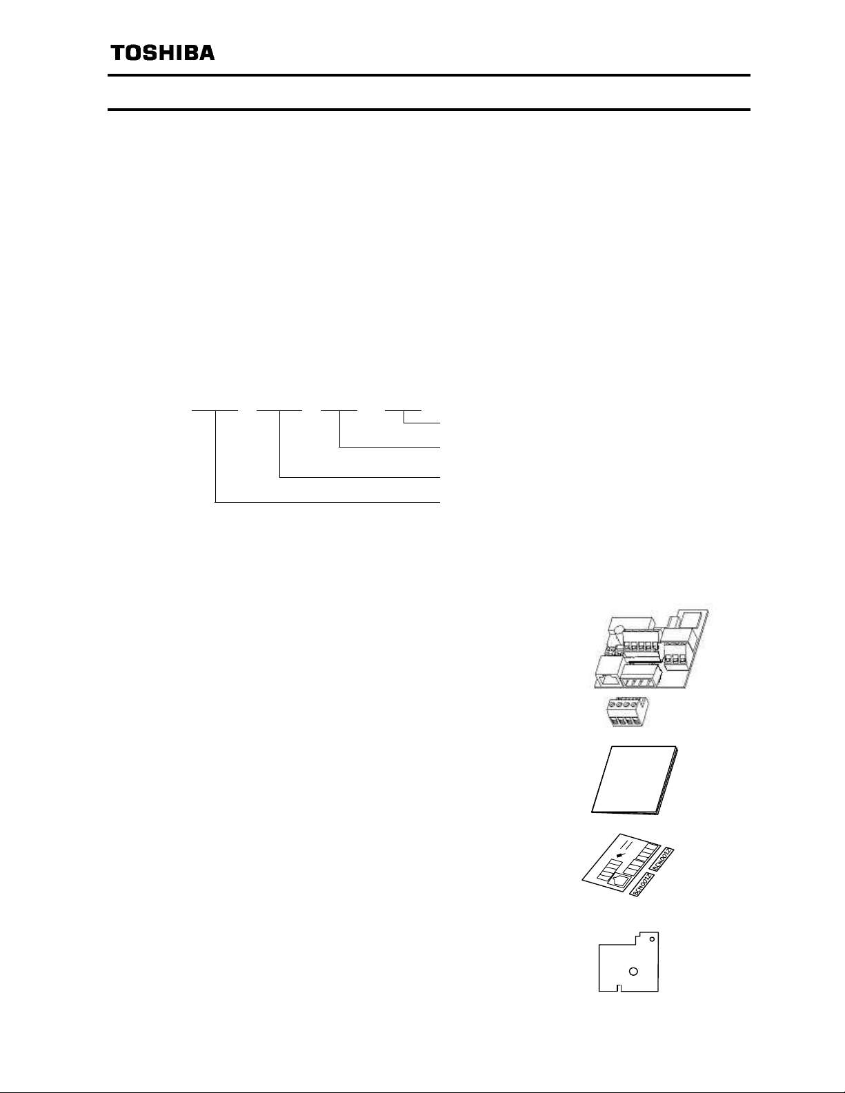
- Part numbering
BCN 002 Z
BACnet
BACnet
®
is a registered trademark of ASHRAE.
network.
Communication Function Manual´: E6581404)
³BACnet®option
0
±
(BCN002Z)´ for TOSVERT VF-FS1 inverter. By
BACnet
BACnet
Revision number
Cable length ( ³Z´ means ³without cable´ )
Model number of BACnet
Symbol of BACnet
option
option
®
network is
®
- Accessory check list
BACnet
packing case, check to see if the following accessories are contained or not.
(1) BACnet option board (BCN002Z)
(2) Instruction manual
(3) Cabling label & Name plate ............................1 sheet
(4) Insulating sheet ...............................................1 sheet
communication option is shipped together with the following accessories. On opening the
Board (BCN002Z) ............................................1 pcs
Connector: MSTB2.5/4-ST-5.08
Manufactured by PHOENIX CONTACT
English (E6581402).......................................1 copy (This book)
(1 cabling label and 2 name plates)
Instruction
Manual
-4-
Page 6

E6581402c
Table of Contents
1. Overview 㨯㨯㨯㨯㨯㨯㨯㨯㨯㨯㨯㨯㨯㨯㨯㨯㨯㨯㨯㨯㨯㨯㨯㨯㨯㨯㨯㨯㨯㨯㨯㨯㨯㨯㨯㨯㨯㨯㨯㨯㨯㨯㨯㨯㨯㨯㨯㨯㨯㨯㨯㨯㨯㨯㨯㨯㨯㨯㨯㨯㨯㨯㨯㨯㨯㨯㨯㨯㨯㨯㨯㨯 6
2. Names and functions㨯㨯㨯㨯㨯㨯㨯㨯㨯㨯㨯㨯㨯㨯㨯㨯㨯㨯㨯㨯㨯㨯㨯㨯㨯㨯㨯㨯㨯㨯㨯㨯㨯㨯㨯㨯㨯㨯㨯㨯㨯㨯㨯㨯㨯㨯㨯㨯㨯㨯㨯㨯㨯㨯㨯㨯㨯㨯㨯㨯㨯㨯 6
2.1. Outline㨯㨯㨯㨯㨯㨯㨯㨯㨯㨯㨯㨯㨯㨯㨯㨯㨯㨯㨯㨯㨯㨯㨯㨯㨯㨯㨯㨯㨯㨯㨯㨯㨯㨯㨯㨯㨯㨯㨯㨯㨯㨯㨯㨯㨯㨯㨯㨯㨯㨯㨯㨯㨯㨯㨯㨯㨯㨯㨯㨯㨯㨯㨯㨯㨯㨯㨯㨯㨯㨯 6
2.2. Use of RS485 communication port㨯㨯㨯㨯㨯㨯㨯㨯㨯㨯㨯㨯㨯㨯㨯㨯㨯㨯㨯㨯㨯㨯㨯㨯㨯㨯㨯㨯㨯㨯㨯㨯㨯㨯㨯㨯㨯㨯㨯㨯㨯㨯㨯㨯㨯㨯 6
2.3. LED indicator 㨯㨯㨯㨯㨯㨯㨯㨯㨯㨯㨯㨯㨯㨯㨯㨯㨯㨯㨯㨯㨯㨯㨯㨯㨯㨯㨯㨯㨯㨯㨯㨯㨯㨯㨯㨯㨯㨯㨯㨯㨯㨯㨯㨯㨯㨯㨯㨯㨯㨯㨯㨯㨯㨯㨯㨯㨯㨯㨯㨯㨯㨯㨯㨯 7
3. Installation and Setup 㨯㨯㨯㨯㨯㨯㨯㨯㨯㨯㨯㨯㨯㨯㨯㨯㨯㨯㨯㨯㨯㨯㨯㨯㨯㨯㨯㨯㨯㨯㨯㨯㨯㨯㨯㨯㨯㨯㨯㨯㨯㨯㨯㨯㨯㨯㨯㨯㨯㨯㨯㨯㨯㨯㨯㨯㨯㨯㨯㨯㨯 8
3.1. Installation method 㨯㨯㨯㨯㨯㨯㨯㨯㨯㨯㨯㨯㨯㨯㨯㨯㨯㨯㨯㨯㨯㨯㨯㨯㨯㨯㨯㨯㨯㨯㨯㨯㨯㨯㨯㨯㨯㨯㨯㨯㨯㨯㨯㨯㨯㨯㨯㨯㨯㨯㨯㨯㨯㨯㨯㨯㨯㨯㨯 8
3.2. Description of terminals 㨯㨯㨯㨯㨯㨯㨯㨯㨯㨯㨯㨯㨯㨯㨯㨯㨯㨯㨯㨯㨯㨯㨯㨯㨯㨯㨯㨯㨯㨯㨯㨯㨯㨯㨯㨯㨯㨯㨯㨯㨯㨯㨯㨯㨯㨯㨯㨯㨯㨯㨯㨯㨯㨯㨯 9
3.3. Network cable connection 㨯㨯㨯㨯㨯㨯㨯㨯㨯㨯㨯㨯㨯㨯㨯㨯㨯㨯㨯㨯㨯㨯㨯㨯㨯㨯㨯㨯㨯㨯㨯㨯㨯㨯㨯㨯㨯㨯㨯㨯㨯㨯㨯㨯㨯㨯㨯㨯㨯㨯㨯㨯 10
3.4. Network configuration㨯㨯㨯㨯㨯㨯㨯㨯㨯㨯㨯㨯㨯㨯㨯㨯㨯㨯㨯㨯㨯㨯㨯㨯㨯㨯㨯㨯㨯㨯㨯㨯㨯㨯㨯㨯㨯㨯㨯㨯㨯㨯㨯㨯㨯㨯㨯㨯㨯㨯㨯㨯㨯㨯㨯㨯 10
3.5. Wiring of a control terminal 㨯㨯㨯㨯㨯㨯㨯㨯㨯㨯㨯㨯㨯㨯㨯㨯㨯㨯㨯㨯㨯㨯㨯㨯㨯㨯㨯㨯㨯㨯㨯㨯㨯㨯㨯㨯㨯㨯㨯㨯㨯㨯㨯㨯㨯㨯㨯㨯㨯㨯㨯 11
4. Parameters 㨯㨯㨯㨯㨯㨯㨯㨯㨯㨯㨯㨯㨯㨯㨯㨯㨯㨯㨯㨯㨯㨯㨯㨯㨯㨯㨯㨯㨯㨯㨯㨯㨯㨯㨯㨯㨯㨯㨯㨯㨯㨯㨯㨯㨯㨯㨯㨯㨯㨯㨯㨯㨯㨯㨯㨯㨯㨯㨯㨯㨯㨯㨯㨯㨯㨯㨯㨯㨯 12
4.1. Communication parameters 㨯㨯㨯㨯㨯㨯㨯㨯㨯㨯㨯㨯㨯㨯㨯㨯㨯㨯㨯㨯㨯㨯㨯㨯㨯㨯㨯㨯㨯㨯㨯㨯㨯㨯㨯㨯㨯㨯㨯㨯㨯㨯㨯㨯㨯㨯㨯㨯㨯㨯 12
5. Specifications 㨯㨯㨯㨯㨯㨯㨯㨯㨯㨯㨯㨯㨯㨯㨯㨯㨯㨯㨯㨯㨯㨯㨯㨯㨯㨯㨯㨯㨯㨯㨯㨯㨯㨯㨯㨯㨯㨯㨯㨯㨯㨯㨯㨯㨯㨯㨯㨯㨯㨯㨯㨯㨯㨯㨯㨯㨯㨯㨯㨯㨯㨯㨯㨯㨯㨯㨯 13
6. Warranty 㨯㨯㨯㨯㨯㨯㨯㨯㨯㨯㨯㨯㨯㨯㨯㨯㨯㨯㨯㨯㨯㨯㨯㨯㨯㨯㨯㨯㨯㨯㨯㨯㨯㨯㨯㨯㨯㨯㨯㨯㨯㨯㨯㨯㨯㨯㨯㨯㨯㨯㨯㨯㨯㨯㨯㨯㨯㨯㨯㨯㨯㨯㨯㨯㨯㨯㨯㨯㨯㨯㨯 14
-5-
Page 7

E6581402c
1. Ov e rview
The BACnet (BCN002Z) interface allows the VF-FS1 inverter to be connected into a BACnet network.
BACnet MS/TP supports a maximum of 32 nodes for one segment.
2. Names and functions
The drawing below shows names and functions of main parts.
2.1. Outline
Connector
Input terminal
SINK/SOURCE
VIB/PTC select SW
Terminal board fixing
screw hole
(M3 screw)
Termination
resistor SW
Communication
condition monitor LED
Optional RS485 communication port
RS485 communication option can be
used. However it makes BACnet
Communication be disabled.
BAGNDSCR
Detachable terminal
Network
communication
2.2. Use of RS485 communication port
Serial communication (2-wire RS485) option can be used. However, while it is connected, the
internal communication line is switched to RS485 then the communication via BACnet network is
disabled. In this case, communication error trip time (f803) is also active. Use RS485 serial
communication option specified by Toshiba.
-6-
Page 8

2.3. LED indicator
The option has two LEDs. Those functions are below table.
E6581402c
COM
Green
ERR
Red
State
A
B
C
D
E
F
OFF
1s
ABC EF
OFF
2s
1s 1s
LEDs
Green LED : OFF
RedLED :Flashing5timesin1second
Green LED : OFF
Red LED :
Flashing 3 times in 2 seconds, Off for 1
second
Green LED : ON
Red LED : OFF 0.5s, ON 0.5s
Green LED :
Flashing 3 times in 2 seconds, Off for 1
second
Red LED : OFF
Green LED : Flashing Intermittent Green
Red LED : --Green LED : --Red LED : Flashing Intermittent Red
ON
OFF
2s
1s
D
Comment
BACnet board failure
Communication loss detected. Confirm the
network condition and connection of the cable.
Invalid configuration detected (ADR > max
master), or an option is connected to RJ45.
Waiting for Auto baud rate detection
Valid message received for this node
Invalid message received (any node)
-7-
Page 9

E6581402c
(
)
3. Installation a nd Setup
3.1. Installation method
Install the BACnet communication option to VF-FS1 as follows.
(1) Turn off the input power of VF-FS1 and wait for at least 10 minutes and then check that the
CHARGE lamp on VF-FS1 is no longer lit.
(2) Open the VF-FS1 front cover, remove the terminal board fixing screw and take off the VF-FS1
standard terminal board.
(Be careful not to lose the terminal board fixing screw when removed since it may be used again.)
(3) Perform wiring an inverter before installing BACnet comm unication option.
(4) Please attach the insulating sheet in VF-FS1.
(Fix to the terminal board fixing screw hole and PWB catch pin.)
(5) Install the BACnet communication option over the insulating sheet and secure it with the board
fixing screw (tightening torque of M3 tapping screw: 0.7 to 0.8Nm).
(6) Set up the SW of the board with the input terminal for sink or source.
(7) Stick the cabling label for BACnet communication option on the standard cabling label stuck on
the reverse side of the VF-FS1 front cover. And stick the BACnet communication option
nameplate near the standard nameplate. (Be careful not to cover slits on the VF-FS1 enclosure.
N.B.: To install or remove the terminal board, make it slide in or out in parallel with board.
Cabling label position
Example
VF-FS1 unit
Board catching pin
Terminal board fixing screw
(M3 screw tightening torque: 0.7 to 0.8Nm)
Board fixing screw hole
Stick the BCN002Z nameplate
like bellow figure.
BCN002Z
BCN002Z
VF-FS1 name plate
VF-FS1 Standard te rminal board
Insulating seat
(attached)
BACnet communication option
BCN002Z
-8-
Page 10

3.2. Description of terminals
C
A
<Control terminals specification>
E6581402c
Terminal
symbol
Function Electrical specifications Internal circuits
B Communication signal (+)
A Communication signal (-)
GND Signal common
BACnet communication
signal
SCR
F
R
VIB
EIA-485
Multifunctional programmable
contact input.
SINK/SOURCE can be
selected with SW.
Multifunction programmable
analog input.
with internal pull-up resistor
for PTC
Shield terminal.
Connect to network ground.
No voltage contact input
,5mAorless
24V
DC
N.B. Use contact parts for low
current.
0to10V
DC
input
Using this terminal as PTC
input, set SW2 to PTC side
and set the parameters
(f645 and f646)to
proper value.
P24
F, R
CC
VIB
GND
SCR
B
A
P24
PTC
PT
TERM
SW4
820
4.7k
4.7k
P10
47k
47k
120
SOURCESINK
15k
15k
3.3k
CC
Control circuit¶s equipotential
terminal
P24 24 VDCpower supply output 24VDC-50mA
FLA
FLB
FLC
Multifunctional programmable
relay contact outputs
1c contact
30V
DC
250V
250V
Danger
Do not change switches settings while the power is on.
Prohibited
Mandatory
It may lead to electric shocks or damage.
Turn off the motor operation signals before setting the parameter and the switch
(SW), when changing the VIB function. Otherwise, the motor may suddenly start
and that may result in injuries.
-0.5A
-1A (cosI=1㧕
AC
-0.5A (cosI=0.4)
AC
P24
FL
FLB
FLC
PTC
P24
Ry
-9-
Page 11

3.3. Network cable connection
Connect the BACnet network cable to communication option as follows.
Title Description
Wire type Shielded twisted cable
Characteristic impedance Between 100 and 130 ohm
Distributed impedance between
conductors
Distributed impedance between
conductors and shield
Less than 100pF per meter
Less than 200pF per meter
Foil or braided shields are acceptable.
Length of an MSTP segment 1200 meters with AWG18 (0.8mm2)
Cable sheath should be peeled off by about 7mm.
For wiring work, use a flat blade screwdriver with a 0.6mm thick and
3.5mm width blade.
mm
⿆
Tightening torque for the terminal block is 0.5Nm.
* Fix a cable so that a communication connector may be not taken the weight of wire.
3.4. Network configuration
E6581402c
Make up the network as follows.
- Transmission/reception signals (A, B)
Make up the communication path by connecting all transmission/reception data cables.
- Signal common (GND)
GND is the signal common.
- Grounding the shield of cable (SCR)
Connect the all shield lines of network cable. The shield shall be grounded at one end only prevent
currents from being created.
- Termination resistor
A termination resistance of 120 ohms plus or minus 5% shall be connected at each of the two ends
of the segment medium. This option has a termination resistor, so if use, set up the termination
resistor SW. (Refer to 2.1 Outline)
At least one set, and no more than two sets, of network bias resistors shall exist for each segment.
This option has local bias resistors.
SW4
B
A
4.7k
120
Termination
GND
510
B
A
GND
SCRSCR
Communication
+5
510
cable
B
A
GND
SCR
Communication
cable
4.7k
47k
TERM
120
Termination
+5
47k
Node with network
bias resistors
Node without
bias resistors
Node with local bias resistors
This option board
N.B.:Do not connect the SCR terminal to the power ground of inverters or other units.
Keep the network cables 20cm or more separate from the power cables to prevent from
malfunctioning due to electromagnetic noise.
-10-
Page 12

E6581402c
r
External
Input terminal
3.5. Wiring of a control terminal
Observe the following when wiring.
-Use0.3to1.5mm
- Remove the sheath of a cable about 7mm (6mm for FLA, FLB, FLC and G/E) from the end of cable.
- Use a flat-headed screwdriver with its blade 0.6mm in thickness and 3.5mm in width.
- Screw tightening torque for the terminal block screws should be 0.5 to 0.6Nm.
N.B.: Keep the control signal cables 20cm or more separate from the power cables to prevent from
malfunctioning due to electromagnetic noise.
N.B.: Provide an inter-lock system stated in below, when using a programmable controller that has
the open collector output.
When the programmable controller is turned off with the inverter is on, the difference between
each control power potential will cause wrong signals to the inverter as shown in below figure.
Provide an inter-lock so that the programmable controller cannot be turned off when the
inverter power is alive.
2
solid/stranded wire (AWG 22 to 16) for control cables.
VF-FS1 + BCN002ZProgrammable controller
+24V
Fuse blowout
detection
circuit
Fuse
+24V supply
COM
Inverte
internal +24V
-11-
Page 13

4. Parameters
4.1. Communication parameters
Set up the inverter parameters as follows. To update, reset the power of inverter. If these
parameters are not set to correct value, this unit can not work normally.
E6581402c
Title Function Description
0: Terminal board
cmod Command mode selection
fmod
f800 Communication rate Set ³1: 19200bps´ (default). 1 1
f801 Parity Set ³1:Even´ (default). 1 1
f803 Communication error trip time
f829 Communication protocol Set ³4: BACnet protocol´ 04
f851
f890 Address Set node address 0 ---
f891 Network baud rate
f892 Network Time-Out
f893 0 ---
f894
f895 MaxMaster
f896 MaxInfoFrame
Frequency setting mode
selection 1
Operation at communication
error by disconnection
Instance number Instance No.= f893 x 1000 + f894
1: Operation panel
2: Serial communication
1: VIA
2: VIB
3: Operation panel
4: Serial communication
5: UP/DOWN from external contact
Set communication time out period.
The way of stop is selected by f603.
0: Inverter stop, communication command,
frequency mode open (by cmod,
fmod)
1: None (continued operation)
2: Deceleration stop
3: Coast stop
4: Communication error (err5 trip)
or Network error (err8 trip)
0: AUTO adaptive
1: 9600
2: 19.2kbps
3: 38.4kbps
4: 76.8kbps
Over 5 is AUTO adaptive.
0: No action
Unit 0.1sec, Setting range : 1 to 65535
Setting range : 0 to 127
Over 127 is limited 127.
Setting range : 0 to 100
Over 100 is limited 100.
Shipment
setting
BACnet
02
14
0 ---
0 ---
0 ---
0 ---
0 ---
0 ---
0 ---
Mandatory
Warni ng
Set up ³Communication error trip function (f803, see the inverter instruction
manual for details)´ to stop the inverter when this option unit is deactivated by an
unusual event such as tripping, an operating error, power outage, failure, etc.
Deactivated option unit may cause an accident, if the ³Communication error trip
function´ is not properly set up.
-12-
Page 14

5. Specifications
A
< Environmental specification >
Item Specification
Service environment Conforms to VF-FS1
Operation temperature Conforms to VF-FS1
Storage temperature
Relativ e humidity 20 to 93% (free from condensation and vapor)
Vibration 5.9m/s2(0.6G) or less (10 to 55 Hz) (To be complied with JIS C0040.)
< BACnet option terminal specification >
Item Specification Note
Communication between
inverter
Applicable model
Communication method MODBUS-RTU
Baud rate 19200bps
Parity Even number
Control power supply 5 V
Logic input terminal
Logic output terminal Nothing
Relay contact output
terminal
Analog input terminals 1 circuit (VIB): 10VDC(RIN= 30kohm) Not isolated
Analog output terminals Nothing
Power supply output 24VDC-50mA Current limit function
-25to+65㷄
VF-FS1
DC
2 circuits (F,R)
Slide switch (SW) enable to select
logical configurations (Source/Sink).
250V
250V
-0.5A
DC
-1A (cosI=1㧕
AC
-0.5A (cosI=0.4)
C
1 circuit (FL):30V
Only one board connection is
available.
Set the inverter parameter
(refer to section 4.1)
Supplied from inverter
Not isolated
Isolated
E6581402c
< BACnet option network specification >
Item Specification
Data link / Physical layers Master-Slave / Token Passing (MS/TP)
Node type Master node
Maximum node 32 nodes per segment
Communication baud rate
Bias resistor and termination
9600bps, 19.2kbps, 38.4kbps, 76.8kbps
supports auto-baud detection
Local bias res istors are mounted.
Termination resistor (120 ohm) can be select by SW.
Detachable terminal block 4-pole (5.08mm pitch)
Terminal block
Manufacturer: PHOENIX CONTACT
Type-Form : MSTB 2,5/4-ST-5.08
-13-
Page 15

E6581402c
6. Warranty
Any part of BACnet communication option that is proved to be defective will be repaired free of
charge under the following conditions:
1. This product will be repaired free of charge, if problem/fault occurs under normal handling
within one year of delivery and is caused obviously by a design or manufacturing defect.
2. The warranty applies only to the delivered product.
3. For the following kinds of failure or damage, the repair cost shall be borne by the customer
even within the warranty period.
i) Failure or damage caused by improper or incorrect use or handling, or unauthorized repair
or modification of the inverter.
ii) Failure or damage caused by the unit falling or an accident during transportation after the
purchase.
iii) Failure or damage caused by fire, salty water or wind, corrosive gas, earthquake, storm or
flood, lightning, abnormal voltage supply, or other natural disasters.
iv) Damage due to the use of BACnet communication option for non-intended purposes.
4. If an additional warranty is provided then those conditions will also apply.
- 14E -
Page 16

 Loading...