

Page 1
·'
Buy: www.ValinOnline.com | Phone 844-385-3099 | Email: CustomerService@valin.com
TOSHIBA
E6581440
TOSVERT VF-PS1 series
BACnet®
Option unit Function Manual
BCN001Z
1.
2. Read this
3.
Make sure that this instruction manual is delivered
Option unit.
in a safe place
All information contained in this manual are subject to change without notice.
Please confirm the latest information on our web site
manual before installing
for
reference.
NOTICE
or
operating the BACnet® Option unit. Keep it
to
the end user
of
BACnet®
Page 2
TOSHIBA
Buy: www.ValinOnline.com | Phone 844-385-3099 | Email: CustomerService@valin.com
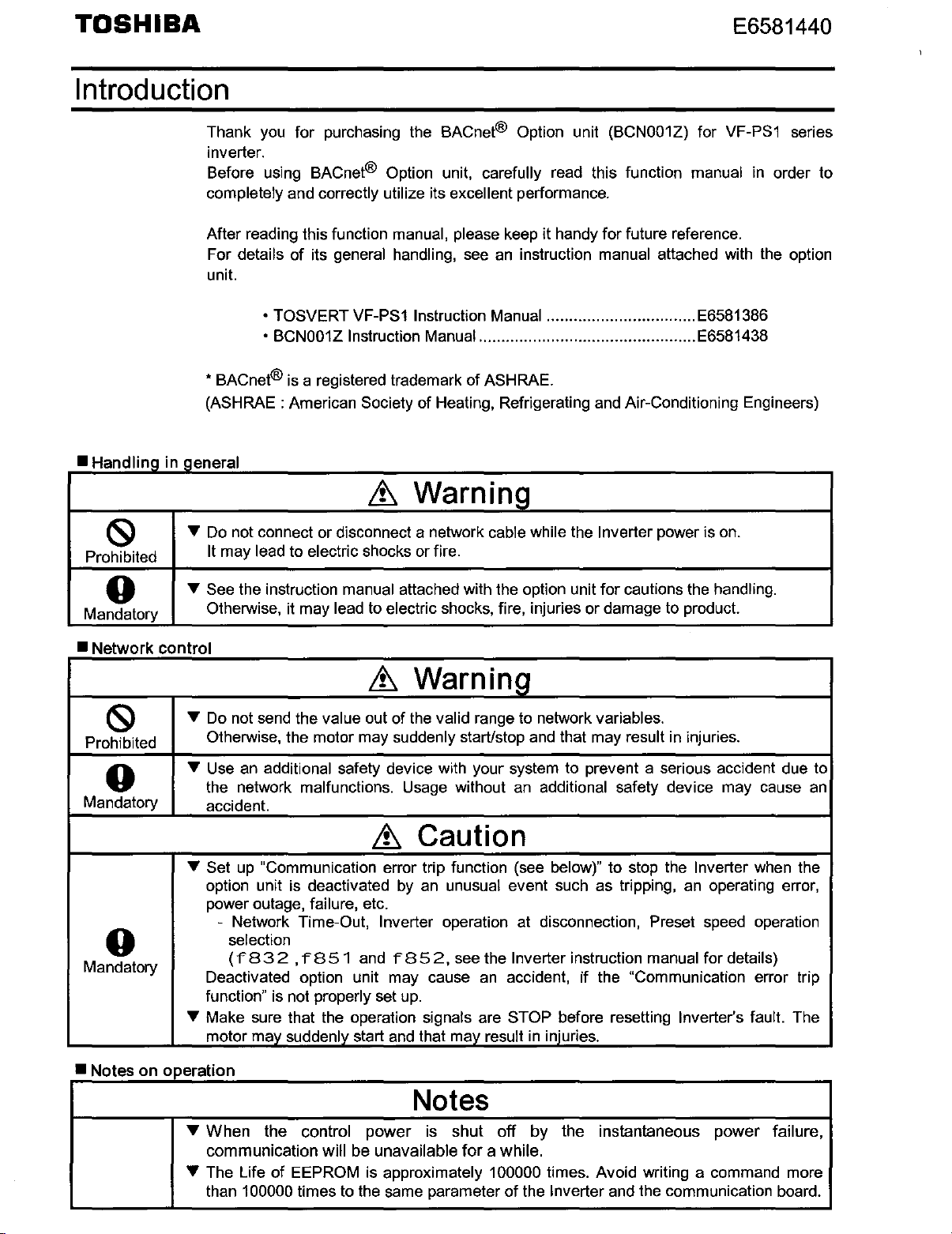
Introduction
E6581440
Handling in general
•
(S)
Prohibited
0
Mandatory
"'
"'
Thank
inverter.
Before using BACnet®
completely and correctly utilize its excellent performance.
After reading this function
For
unit.
* BACnet® is a registered trademark of ASHRAE.
(ASHRAE : American Society
Do
It may lead to electric shocks or fire.
See the instruction manual attached with the option unit for cautions the handling.
Otherwise, ii may
you
for purchasing the BACnet® Option unit (BCN001Z) for VF-PS1 series
Option unit, carefully read this function manual in order to
manual, please keep
details of its general handling, see
• TOSVERT VF-PS1 Instruction Manual ................................. E6581386
• BCN001Z Instruction Manual ................................................ E6581438
of
Healing, Refrigerating and Air-Conditioning Engineers)
Warnina
&
not connect or disconnect a network cable while the Inverter power is on.
lead to electric shocks, fire, injuries or damage to product.
ii
handy for future reference.
an
instruction manual attached with the option
•Network
(S)
Prohibited
0
Mandatory
0
Mandatory
•Notes
control
"'
Do
Otherwise, the motor may
"'
Use an additional safety device with your system to prevent a serious accident due to
the network malfunctions.
accident.
"'
Set
option unit is deactivated
power outage,
- Network Time-Out, Inverter operation at disconnection, Preset speed operation
Deactivated option unit may cause
function" is not properly set
"'
Make sure that the operation signals are STOP before resetting Inverter's fault. The
motor may suddenly start
on operation
"'When
communication will be
"'
The Life of EEPROM is approximately 100000 limes. Avoid writing a command more
than
Warnina
&
not send the value out of
up
"Communication error trip function (see below)" to stop the Inverter when the
failure, etc.
selection
(f
83
2 , f
851
and f
the
valid range to network variables.
suddenly starUstop and that may result
Usage without an additional safety device may cause
Caution
&
by
an unusual event such as tripping, an operating error,
85
2,
see the Inverter instruction manual for details)
an
up.
and
that may result
accident,
in
if
injuries.
the "Communication error
in
injuries.
Notes
the control power is
unavailable
100000 times to the same parameter of the Inverter and the communication board.
shut
for
off
a while.
by
the
instantaneous power failure,
an
trip
Page 3
TOSHIBA
Buy: www.ValinOnline.com | Phone 844-385-3099 | Email: CustomerService@valin.com
E6581440
Table
1.
OVERVIEW ........................................................................................................................................... 3
2.
NAMES AND FUNCTIONS ................................................................................................................... 3
2.1. Outline ............................................................................................................................................ 3
2.2. BACnet® Connector ....................................................................................................................... 3
2.3. LED indicator .................................................................................................................................. 4
2.4. MAC address setting ....................................................................................................................... 5
3.
VF-PS1 PARAMETERS ........................................................................................................................ 7
3.1. Communication parameters ............................................................................................................ 7
3.2. Network Baud rate ( f" 8 3 1 ) ............................................................................................................ 8
3.3. Network error detection
3.4. Instance
3.5. Max Master (
3.6. Maxlnfoframe
3.7. MAC address
3.8. Number
4.
FUNCTIONS ......................................................................................................................................... 9
4.1. Object I Property support Matrix ..................................................................................................... 9
4.2. Drive 1/0 Objects ..........................................................................................................................
4.2.1. Binary Input Object Instance ..................................................................................................
4.2.2. Binary Output Object Instance ...............................................................................................
4.2.3. Binary Value Objects Instance ...............................................................................................
4.2.4. Analog Input Object Instance ................................................................................................. 13
4.2.5. Analog Output Object Instance .............................................................................................. 13
4.2.6. Analog Value Object Instance ................................................................................................ 14
4.3. Device Objects ............................................................................................................................. 15
5.
MAILBOX FUNCTION POINTS .......................................................................................................... 16
5.1. VF-PS1 Fault code ....................................................................................................................... 17
6.
SPECIFICATIONS .............................................................................................................................. 18
of
Contents
Number(f"833,
f"
of
motor poles for communication(
("f
832,
f"834)
8 3
5)
...................................................................................................................... 8
(f"836)
monitor(f"853)
.................................................................................................................. 8
f"
851,
....................................................................................................... 8
"f
852)
.............................................................................................. 8
f"
........................................................................ 8
8 5
6)
....................................................................... 8
10
10
11
12
Page 4
TOSHIBA
Buy: www.ValinOnline.com | Phone 844-385-3099 | Email: CustomerService@valin.com
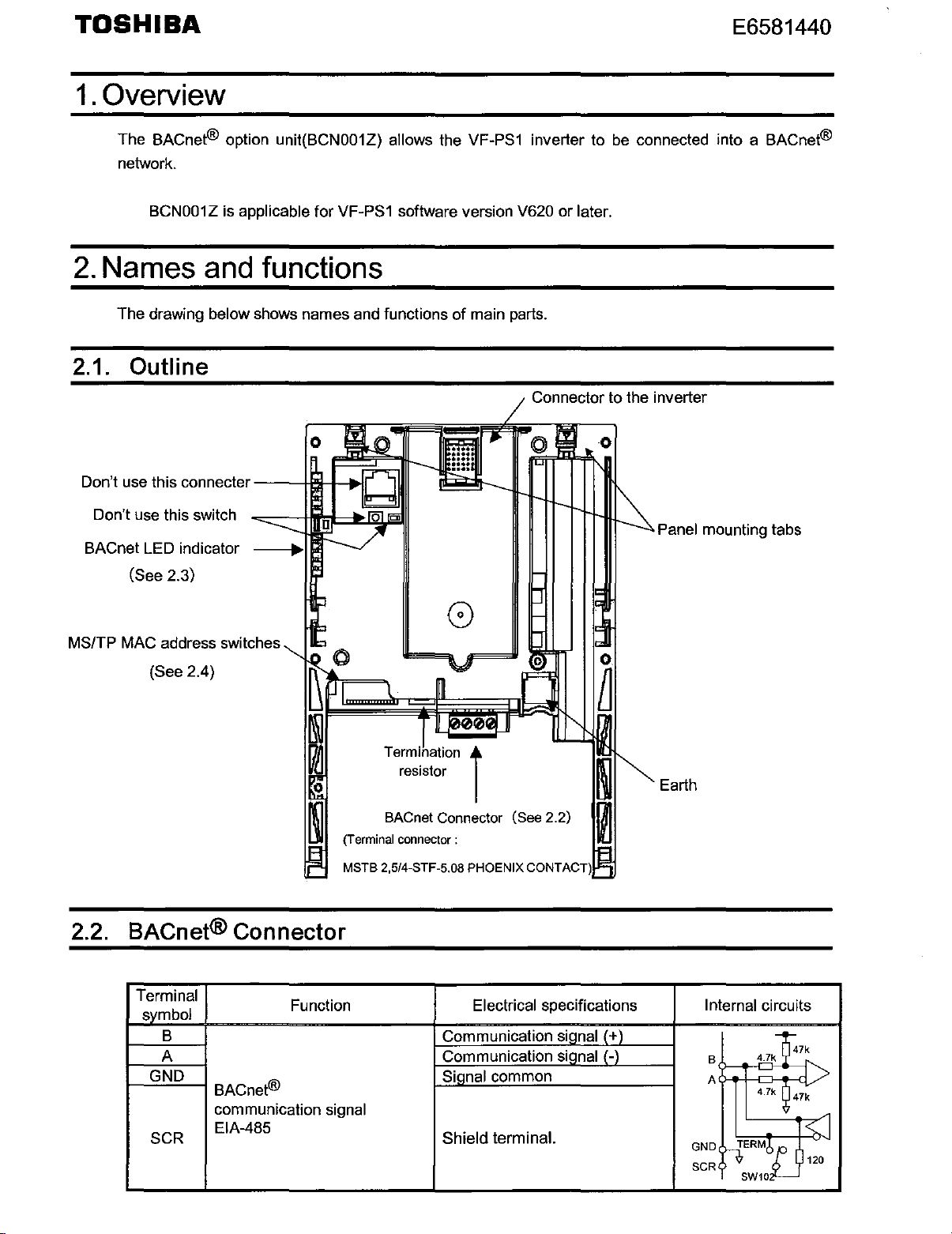
1.
Overview
E6581440
The BACnet® option unit(BCN001Z) allows the VF-PS1 inverter to
network.
BCN001Z is applicable for VF-PS1 software version V620 or later.
2.
Names
The drawing below shows names and functions
and
functions
of
main parts.
2.1. Outline
Don't use this connecter
Don't use this switch
BACnet LED indicator
(See 2.3)
---+
be
connected into a BACnet®
Connector to the inverter
0
Panel
mounting tabs
MS/TP MAC address switches
(See 2.4)
2.2. BACnet® Connector
Terminal
svmbol
B Communication sianal I+ l
A Communication sianal 1-l
GND
SCR
BACnet®
communication
EIA-485
Function
signal
0
Termination
resistor
BACnet Connector (See 2.2)
(Terminal
MSTB 2,5/4-STF-5.08 PHOENIX CONTACT)
connector
i
:
Electrical specifications
Sianal common
Shield terminal.
Earth
Internal circuits
~kf7k
B
A
GNDrlERM~
SCR
4.7
4.7k
)
SW10
~
47k
I<
~
I
I
120
Page 5
TOSHIBA
Buy: www.ValinOnline.com | Phone 844-385-3099 | Email: CustomerService@valin.com
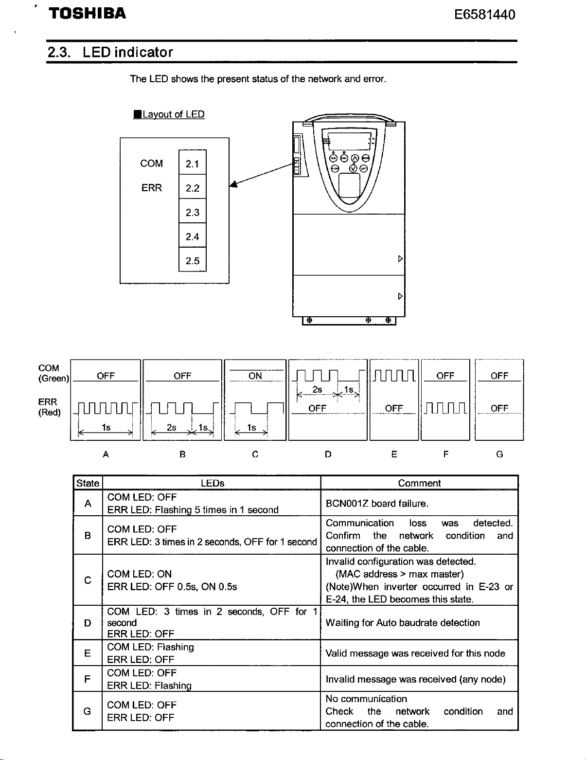
2.3. LED indicator
E6581440
The LED shows the present status
•Layout
COM
ERR 2.2
of
LED
2.1
2.3
2.4
2.5
of
the network and error.
I>
COM
(Green)
ERR
(Red)
__
O~F~F~--11--~0~F~F--11
JlIU1Ilflf
1s
:-
A B c D E F G
State LEDs Comment
COM LED: OFF
A
ERR LED: Flashing 5 times in 1 second
COM LED: OFF
B
ERR LED: 3 times in 2 seconds,
COM LED: ON (MAC address > max master)
c
ERR LED:
COM LED: 3 times in 2 seconds, OFF for 1
second Waiting
D
ERR LED:
COM LED: Flashing
E
ERR LED:
COM LED:
F
ERR LED:
COM
G
ERR LED:
JUUL_[
ic
-:
OFF
OFF
OFF
Flashing
LED:
OFF
2s
)!C
1s
!
3
0.5s. ON 0.5s (Note)When inverter occurred in E-23 or
OFF
OFF
ON
_fl____Jl
'c
1s
OFF
JUUL_[
!<
__
11
;
3
for 1 second
JUUUl
2s
)«
1s)
0=F'-'-F
___
BCN001Z
Communication loss was detected.
Confirm the network condition and
connection
Invalid configuration was detected.
E-24, the LED becomes this state.
Valid
Invalid message was received (any node)
No
Check the network condition and
connection
11.---00c.c.F'-F
board failure.
for
message was received
communication
_
of
the cable.
Auto baudrate detection
of
the cable.
OFF
for
this node
OFF
OFF
Page 6

TOSHIBA
Buy: www.ValinOnline.com | Phone 844-385-3099 | Email: CustomerService@valin.com
E6581440
2.4.
~
ID
0
1
2
3
4
5
6
7
8
9
10
11
12
13
14
15
16
17
18
19
20
21
22
23
24
25
26
27
28
29
30
31
MAC
address setting
The DIP switch
Each
DIP switch is
on
the circuit board
ON
The MAC address must
segment.
.j.
z
0
1 2 3 4 5 6 7 8
'
1 2 3 4
OFF10FF
OFF OFF OFF OFF
OFF OFF OFF I OFF
OFF
OFF
OFFiOFFJOFF
OFF
OFFIOFF OFF OFF
OFF I OFF
OFF OFF OFF OFF ON OFF OFF! ON
OFF OFF OFF OFF
OFF OFF
OFF OFF I OFF OFFI
OFF OFFiOFF
OFF OFF[OFF10FF!
OFF OFF OFF
OFF OFF OFF
OFF OFF OFF
OFF OFF
OFFiOFF
OFF/OFF OFF ON OFF
OFF[OFF
OFF OFF I OFF
OFF
OFF OFF
OFF OFF OFF
OFF OFF OFF
OFF
OFF OFF OFF
OFF OFF OFF
OFF
OFF.OFF
OFF OFF OFF OFF OFF OFF
OFF
I OFF I OFF
OFF I OFF OFF
I OFF
OFF OFF
OFF OFF ON I OFF' OFF OFF
OFF
OFF ON
OFF ON
OFF
OFFiOFF
OFF'
OFF OFF
OFF OFF
OFF
5 6
OFF OFFI
OFF
OFF ON iOFF
OFF
OFF OFF
OFF ON
OFF
OFF
ON
OFF
ON I ON
OFF
ON i ON
OFF ON IOFF
ON
OFF!
ON
OFF
ON
I ON
OFFI
ON
I ON
ON
ON
OFFI
ON
ON
ON
OFF OFF
ON
OFF OFFIOFF!
OFF OFFI ON !OFF
OFF[
OFF
ON
ON
OFF
ON
ON
OFF
ON!
ON
OFF ' ON
ON
ON OFF OFF OFF
ON
ON
ON
ON
ONION10N
ON
ON
OFF OFF ON
ON
ON
OFF
ON
OFF ON ON
ON OFF OFF
ON
ON
ON ON
ON
ON
of
the option is used to set a MSfTP MAC address.
when it is flipped to the lower position.
be
unique
'
I 8
7
ON
ONiON
OFF I OFF
!OFF!
ON
IOFF
I ON
ON.ON
loFF!OFF
OFFi
ON
ON iOFF
ON!ON
OFF!OFF
ON
ON
ON
loFFIOFF
iOFF ON
OFF
ON
ON
ON
ON
OFF
OFF ON
OFF
ON ON
and
not match any other device
I
1
~
ID
32
33
34
35
36
37
38
39
40
41
42
43
44
45
46
47
48
49
50
51
52
53
54
55
56
57
58
59
60
61
62
63
2 3
OFF OFF ON OFF OFF OFF OFF OFF
OFF OFF ON OFF OFF OFF OFF
OFF
OFF
OFF
OFF
OFF
OFF
OFF OFF
OFF OFF
OFF/OFF
OFF10FF
OFF OFF ON OFF
OFF
OFF
OFF
OFF ON
OFF OFF
OFF OFF
OFF
OFF
OFF
OFFI
OFF
OFFI
OFF
OFF
OFF OFF ON ON
OFF
OFF ON ON
OFF OFF ON ON
OFF OFF ON ON OFF ON OFF
OFF I OFF ON
OFF!OFF ON
OFF'OFF
OFF OFF ON
OFF
OFF ON
OFF
OFF
OFF OFF
OFF
OFF
OFF
OFF
OFF
OFF ON ON
on
4 5
ON OFF OFF OFF
OFF OFF OFF
ON
OFF OFF
ON
ON
OFF
ON
OFF
OFF
ON
OFF
ON
ON OFF
OFF
ON
OFF
ON
OFF
ON
OFF
OFF
ON
ON
ON
ON OFF
ON
ON
ON
ON
ON
ON ON
ON ON
ON ON
ON ON
ON ON
ON
ON ON
ON
6 7 8
ON
OFF
ON
OFF1
ON
OFF/ ON ON
ON iOFF OFF OFF
ON
iOFF
ON
iOFF ON
ON
!OFF
ON i ON
ON I ON
ON I ON
ON 1 ON
OFF
OFF OFF OFF
OFF OFF ON
OFF
OFF ON OFF
OFF
OFF ON
OFF
ON OFF OFF
OFF
ON
OFF
ON'
ON
OFF OFF OFF
OFF OFF
OFF
ON
OFF ON ON
ON ON
ON OFF ON
ON ON OFF
ON
ON ON
a network
ON
OFF
ON
ON ON
OFF OFF
OFF ON
ON OFF
ON
ON
OFF
OFF
ON
ON
JOFF
OFF
ON
'OFF
ON OFF
ON
ON
ON
ON
OFF
ON
ON
ON
ON
OFF
ON
OFF
OFF
ON
Page 7

.
Buy: www.ValinOnline.com | Phone 844-385-3099 | Email: CustomerService@valin.com
TOSHIBA
E6581440
I~
I
64
1 2 3
OFF ON
4
5 6
OFFiOFFiOFF
7
OFF.OFF OFF 96 OFF ON ON
65 OFFi ON OFFIOFF OFF OFF OFF ON
66
67
68
69 OFF
70
71
72
73 OFF!
74
75 OFFI ON
76
77
78
79 OFF ON
80 OFF ON OFF ON ,OFF
81
82
83
84
85 OFFi
86
87
88 OFF ON OFF ON ON
89
90 OFF ON OFF ON ON OFF
91
92 OFF
93
94
95 OFF
ON
OFF!
OFF
OFFi
OFFI
OFFi
OFFI
OFFI
OFF
OFFi
OFF
OFF ON
OFF
OFFI
OFFi
OFF
OFF ON OFF ON OFF• ON
OFF ON
OFF
OFF
OFF
OFFiOFFiOFF
ON
OFFlOFF'OFFiOFF
ON
IOFFlOFFIOFFI
ON
OFFiOFFiOFF
ON
IOFF OFFlOFF
ON
/OFF/OFF/OFF
ON OFF I OFF ON
OFF I OFF
ON
ON
loFFlOFFI
lOFFiOFFI
ON
OFF OFF ON
ON
IOFF OFFI ON ON
ON
OFF'OFF
OFF OFF
ON OFF
OFFI
ON
ON
ON
ON
ON
ON
ON
ON
ON
ON
ON OFF
OFFI
ON
OFF'
OFFi ON
ON
'OFF
OFF
ON
OFF ON
ON
OFFI
OFF' ON ON
OFF' ON
OFF; ON
OFF ON ON
OFF. ON OFF 98
ON
ON
ON,ON
ON,ON
OFF OFF OFF 104 OFF
OFF OFF ON 105
ON
ON IOFF
ON
IOFF ON
ON
ON ON OFF 110 OFF ON
ON
ON ON ON
ON
OFF·OFF·OFF 112 OFF
OFF.OFF
OFF· ON :OFF
OFF' ON
OFF
OFF I ON i OFF OFF 116 OFF ON ON
/OFF/ ON OFF ON
OFF ON
OFF OFF OFF
OFF OFF
ON
ON
OFF
ON
ON
ONI
ON
ON
ON·
ON.
OFF OFF
OFF ON
ON OFF
·oFF'OFF
OFF: ON
ON 'OFF
ON'ON
ON
ON'
'OFF OFF 124 OFFI ON
OFF' ON
ON OFF 126
ON ON 127
8
~
ID
1 2 3 4 5 6 7
OFF OFF
97 OFF ON ON OFF
OFF ON
ON 99
100
101
OFF
ON 103 OFF ON ON /OFF
102
OFF
OFF ON ON
OFF ON ON OFF
OFF
OFF
106 OFF ON
ON
107
108
OFF
OFF ON ON
109 OFF ON I ON
111
ON 113
OFF ON
OFF
114 OFF ON
ON
115 OFF ON ON
117
OFF
118 OFF ON
119 OFF ON
120
ON
,OFF 122
ON
121
123
OFF!
OFFI ON
OFFi
OFF'
125 OFF! ON ON
OFFi
OFF
ON
OFF OFF I OFF I
ON OFF OFF I OFF I
ON
OFF
ON iOFF OFF
ON
ON
ONi
ON I
ONi
ONi
ON I
ON
ON
ON
ON I ON
ON
ON.
lOFF
IOFF
ON
I ON
!oFFI
ON OFF! ON OFFI
IOFFI
!OFF
OFFi ON
ON
IOFF
I
ON
ON
ON
ON OFF OFFIOFFI ON
ON
I
ON ON
ON
ON
ON ON ;OFF ON OFF ON
ON OFF
ON
ON ON
i
ON
I
ON
I
ON ON
ON
ON,
ON
ONI
ON ON
ON
ON ON
ON
ON
8
OFFJOFF OFF
OFFIOFFIOFFI
OFFI
ON
OFF'
ON IOFF ON
ON I ON IOFF
OFFI ON
IOFFlOFFiOFF
ON
ON
OFF!OFF ON
ON
OFFl ON !OFF
ON ON
ON'
ON
ON/
ON
ONI
OFF
OFFiOFFiOFF
OFFIOFFI ON
iOFFIOFFI ON ON
OFF! ON OFFiOFF
ON
OFF
ONi
ON OFF!OFF OFF
ON
OFF OFF
ON OFFi ON OFF
ON
ON !OFF
ON ON
lOFFIOFF
JON
j ON
ONION
iOFFiOFF
IOFF ON
iOFF
ON
ON
,ON
OFF
ON
OFF
ON'ON
ON
i ON OFF ON ON
ON I OFF I OFF
ON.ON
ON
ON'
OFF ON
ON ON OFF
ON
ON
ON
Page 8

TOSHIBA
Buy: www.ValinOnline.com | Phone 844-385-3099 | Email: CustomerService@valin.com
3.
VF-PS 1 Parameters
3.1. Communication parameters
Set
up
the
inverter
to
correct value, this unit can not
parameters
as
follows.
work
To
normally.
update, reset
of
inverter. If these parameters
E6581440
are
not set
•
..
·!!:'
Title
f831
f832
f833°
f834
f835
f836
f851
f852
Function Description
Network Baudrate (*1) (*2)
Network Time-Out (*1) (*2)
-
..
)..'":5
,,,
Instance numbe • ) *2)
/
MaxMaster(*1)
Maxinfoframe("1) ("2)
Inverter operation at the
communications
(Network
Preset speed operation
selection
'
i<•f<../
wire breaks)
1'1~l
··~
~
Uc.J~=-
("2)
loss
action
0:
AUTO
3: 38400bps,4: 76800bps,Over 5
No action
0:
Unit
4»nl
Instance No.=
f834
Instance No. < 4194304
Setting range : 0 to 127
Over
Setting range : 0 to 100
0
same as
0: Inverter stop,
1:
None (continued operation)
2: Deceleration stop
3:
Coast stop
4:
Network error ( e r r 8 trip)
5:
Preset speed operation by f 8 5 2 setting
O:None
1-15:Preset speed operation (by parameter setting)
adaptive, 1: 9600bps,2: 19200bps,
0.1
sec, Setting range: 1 - 65535
f833x1000
< 1000
127 is limited 127.
1.
Over 100 is limited 100 internally.
communication command,
mode open (by
cmod,
fmod)
+
is
f834
AUTO
adaptive.
frequency
Factory
setting
0000
0000
0000
0000
0000
0000
0
0
f853
f856
f899
fe66
fe67
MAC address ("2)
(Read Only)
Number of motor poles for
communication ("2)
Network
Add-on
version(Under side option)
Add-on option 2
version(Panel side)
option reset setting
option 1
("1) These parameters are displayed by the Panel as a hexadecimal number.
("2) This parameter
changing a set point.
is
BCN001Z MSfTP
(Set DIP
1-B:Number
(It
O:None
1 :Reset option unit and inverter
CPU
Option unit software version number.
CPU
effective by reset. Please reset (power supply reset or
switches on the board)
is used to monitor the rotational speed of the motor)
If
this monitor value is '123',that means version '1.23'.
MAC address monitor.
of
motor pole pairs
f899=1)
2(4
-
poles)
0
-
-
after
Page 9

TOSHIBA
Buy: www.ValinOnline.com | Phone 844-385-3099 | Email: CustomerService@valin.com
E6581440
3.2. Network Baudrate
Set the network baudrate to F 8 3 1 . Set the same baudrate in the network. If set AUTO
baudrate. the option unit detects network baudrate automatically.
(f831)
3.3. Network error detection
Set the network communication loss action time to r 8 3
starts from the first receiving of the proper frame message. The action of the network
communication loss is set
If F 8
communication loss was detected.
In
speed operation selection( F 8 5 2
3.4. Instance Number
Set BACnet® Object Instance number. The instance number should not be duplicate
the network. The instance number is 22bit data length, and set the number
board as
51
is set other than
addition, in the case of
(f833,
below.
Instance
number=
r834
Instance
number< 4194304
(f832,
by
F 8 5 1 .
4,
F851
f834)
F833
< 1000
f851,
·
t'
alarm appear at the inverter panel display when
= 5, the inverter output designated frequency
)".
x 1000 +
F834
f852)
2.
The network loss detection
in
of
the option
"Preset
in
3.5.
3.6. Maxlnfoframe ( f 8 3
3.7.
Max
Master ( f 8 3
Set the maximum master number of the segment. The BACnet® option unit polls master
station node from
response time.
Set the max information frame number to
MAC
address
Set the station MAC address to a switch(SW102)
address
5)
0 to MaxMaster,
6)
monitor(f853)
should
be
a unique number
r 8 5 3 is the monitor parameter of MAC address that is set to the address switch
option board.
3.8. Number of motor poles for
so
set MaxMaster to
send
from this node. Not need to change.
on
on
the MS/TP network segment.
be
small number to
the option board. This station MAC
communication(f856)
be
a fast
on
the
Set the number
This parameter is used
communication.
of
motor pole pairs to calculate the motor rotational speed.
only when the motor rotational speed is monitored with a
Page 10

TOSHIBA
Buy: www.ValinOnline.com | Phone 844-385-3099 | Email: CustomerService@valin.com
4.Functions
This
option board is based on BACnet® "Application Specific Controller" (B-ASC).
4.1. Object I Property support Matrix
This
option board supports below table objects and properties.
Property
Object Identifier
Obiect Name
Object Type
System Status
Vendor Name
Vendor Identifier
Model Name
Finnware
Revision
Appl Software Revision
Protocol Version
Protocol Revision
Services Supported
Object Types Supported
Object List
Max APDU Length
Segmentation Support
APDU Timeout
Number APDU Retries
Max Master
Max Info Frames
Device Address Binding
Database Revision
Present Value
Status Flags
Event State
Out-of-Service
Units
Prioritv Array
Relinquish Default
Polaritv
Active Text
Inactive Text
Device
,/
,/ ,/
,/
,/
,/
,/
,/
,/
,/
,/
,/
,/
,/
,/
,/
,/
,/
,/
,/
,/
,/
,/
Binary
Input
,/ ,/
,/ ,/
,/
,/ ,/
,/
,/
,/ ,/
,/ ,/ ,/
,/ ,/ ,/
Binary Binary
Output Value
Object Type
Analog
,/
,/ ,/
,/
,/ ,/ ,/
,/
,/
,/
./*2
,/
./
,/
,/
,/
*1
*2
·1
Input
,/
,/
,/
,/ ,/
,/ ,/
,/
,/
E6581440
Analog
Output
,/ ,/
,/ ,/
,/ ,/
,/ ,/
,/
,/
,/
,/
Analog
Value
,/
,/
,/
,/
,/
·1
,/
·1
*1: For commandable object only.
*2: Priority
Array 6 are not supported.
Page 11

TOSHIBA
Buy: www.ValinOnline.com | Phone 844-385-3099 | Email: CustomerService@valin.com
4.2. Drive 1/0 Objects
4.2.1. Binary Input Object Instance
E6581440
Binary input objects
These objects
BACnet®
terminal
indicate a
Instance
Binarv input
Binary input
Binarv input
Binary inPut
Binarv input
Binarv input #5 •
Binarv input
Binarv input
Binarv input
ID
#0
#1
#2
#3
#4
#6
#7
#9
allow
to
monitor
are
read only.
network, Binary input object can be used to. Binary input #0 is FL labeled
monitor.
terminal level that
Object Name Description
RO
R02ACT
R03ACT
•
R04ACT
•
RO
R06ACT
DI
1 ACT Inverter F terminal monitor
DI
2ACT
DI
4ACT
1 ACT
5ACT
Whatever
Inverter
Inverter
Inverter OUT2 terminal monitor
Inverter
Inverter OUT5 terminal monitor
Inverter OUT6 terminal monitor
Inverter R terminal monitor
Inverter
If
function
inverter
FL
OUT1
R2
RES
the
inverter actual terminal
it is necessary
is
set
would
terminal monitor
terminal monitor
terminal monitor
terminal monitor
to
try
ON/OFF
to
read
inverter
the
FL terminal by parameter r 1 3
to
output.
1r1
32
cr130
1r1
31
terminal output
..
l
..
>
..
l
cr138**l
<r136
1r1
37
..
)
··>
status.
Active I
Inactive
ON/OFF
ON
ON
ON
ON/OFF
ON/OFF
ON/OFF
ON/OFF
ON
status
/OFF
I OFF
I OFF
/OFF
via
2,
Acee
SS
R
R
R
R
R
R
R
R
R
it
Binarv inout
Binarv input
Binarv input #12
Binarv input #13
Binarv input #14 •
Binary input #15 •
Binarv input #16
Binary inout #17
•These
••These parameters affect the function of terminals.
R=Read-only, W=Writable, C=Commandable.
#10
#11
are enabled with ETB004Z(Expansion
DI
5ACT
DI
6ACT
DI
7 ACT Inverter
DI
BACT
DI
9ACT
DI
10
ACT
•
DI
11
ACT
•
DI
12ACT
Inverter
Inverter
Inverter RR/S4 terminal monitor
Inverter Ll5 terminal monitor
Inverter Ll6 terminal monitor
Inverter
Inverter
S1
terminal monitor
S2
terminal monitor
S3
terminal monitor
LI?
terminal monitor
LIB
terminal monitor
10
card option).
ON
/OFF
ON/OFF
ON
/OFF
ON
/OFF
ON/OFF
ON/OFF
ON/OFF
ON/OFF
R
R
R
R
R
R
R
R
Page 12

TOSHIBA
Buy: www.ValinOnline.com | Phone 844-385-3099 | Email: CustomerService@valin.com
4.2.2. Binary Output Object Instance
Binary output objects allow to control output terminals via BACnet® network.
Set the terminal function parameter( see below table) before control output terminals.
These commandable objects can be used
property.
E6581440
for
priority-array and relinquish-default
Instance
Binarv
Binarv Output
Binarv Outout #2
Binarv
Binarv Outout #4
Binary Output #5
Binary Output #3.#4.#5:
R=Read-only. W=Writable. C=Commandable.
ID
Outout
Outnut #3
tl-0
#1
Object Name Description
RO
1 CMD
R02CMD
R03CMD
R04CMD
R05CMD
R06CMD
These
are
FL
terminal control.
OUT1
OUT2 terminal control.
R2
terminal control.
OUT3 terminal control.
OUT4 terminal control.
enabled
with
terminal control.
ETB004Z(Expansion
(f132
(f130=94)
(f
(f138=98)
(f136=100)
(f137=102)
1
10
31
card
=92)
= 96)
option).
Active I
Inactive
ON
I OFF
ON
/OFF
ON
/OFF
ON/OFF
ON/OFF
ON
/OFF
Access
c
c
c
c
c
c
Page 13

TOSHIBA
Buy: www.ValinOnline.com | Phone 844-385-3099 | Email: CustomerService@valin.com
E6581440
4.2.3.
Binary
Value
tlO
#1
#2
#4
#U
#7
Binary Value Objects Instance
Binary
RUN/STOP command.
Commandable objects can be used
ID
Object Name Description
RUN/STOP ACT
FWD/REV
FAULT ACT
HAND/AUTO ACT
MAINTREQ
DRIVE READY R
ACT
value
objects
Indicates the drive
(This obiect access to oarameter
Indicates
(This object access to parameter
Indicates
Indicates
Commutative operation time alarm status
(This obiect access to parameter
The
(This object access to parameter
allow
to
monitor
for
priority-array and relinquish-default property.
run
status
the motor rotation's direction
the drive's fault status FAUL TED/NONE
if the drive is locally controlled
VSD
is
ready and waits a start command READY/NOT
inverter status and send command such
Active/
Inactive Text
f
dO
1 bit10l
f
dO
1 bit9)
or
not HAND/AUTO
f c
91
bit10)
f d O 1 bit14)
RUNS/READY
REV/FWD
YES/NO R
READY
as
Access
R
R
R
R
#8
#10
#11
#14
#15
#16
#18
#19
#20
#21
#22
R=Read-only, W=Writable,
ATSETPOINT
RUN/STOP CMD Commands a drive start
FWD/REVCMD
FAULT RESET Command to reset faults RESET/NO c
MBOX READ
MBOXWRITE
SP1PRESET
SP2PRESET Preset speed operation frequency 2 SP2/NONE c
SP3PRESET Preset soeed ooeration freauencv 3 SP2/NONE c
SPTSEL
CMDSEL
The VSD has reached the target speed REACHED/NO
START/STOP
Commands a motor direction's change REV/FWD
Command to read parameter READ/RESET
Command to write parameter WRITE/RESET
Preset
speed operation frequency 1 SP1/NONE
Frequency priority selection
(This object access to parameter f
Command priority selection
(This obiect access to oarameter f
C=Commandable.
a06
a06
bit14)
bit15)
ENABLED/OFF c
ENABLED/OFF
R
c
c
w
w
c
c
Page 14

TOSHIBA
Buy: www.ValinOnline.com | Phone 844-385-3099 | Email: CustomerService@valin.com
E6581440
4.2.4.
Analog Input Object Instance
The analog input objects allow to monitor inverter analog input terminal level.
These objects only read inverter parameters those are prepared as read only monitor
parameters( from f e 3 5 to f e 3 9
These objects present-value unit is "%" unit. and present-value=100.0% mean analog
input terminals are a full range input level.
Instance
Analoa lnout
Analoa Input
Analoq Input
Analoq Input
Analoq Input
Analog Input
R=Read-only, W=Writable. C=Commandable.
ID
#3,#4 :
Object Name
#-0
ANALOG INPUT 1 RR/S4 analoa inout level.
#1
ANALOG INPUT 2
#2 ANALOG INPUT 3
#3 ANALOG INPUT 4
#4
ANALOG INPUT 5 Al2 analoq input level.
These
are
enabled
Description
VI/II analoa inout level.
RX
Al1
with
ETB004Z(Expansion
).
analoa inout level.
analoa input level.
10
card
option).
{fe35)
{fe36)
{fe37l
lfe38l
lfe39)
Access
R
R
R
R
R
4.2.5.
Analog Output Object Instance
The
analog output objects allow to central inverter analag(AM,FM, ... ) output levels, and
also can be used priority-array and relinquish-default praperty.
These objects
meter function
Instance
Analoa output #0
Analoa
Analog
Analog output #3
Analog output #2,#3 :
ID
output
output #2
R=Read-only, W=Writable, C=Commandable.
Obiect Name Description
A01COMMAND
#1
A02COMMAND
A03COMMAND
A04COMMAND
only write to inverter parameters(
selection parameters( see below table} to 31.
Set
fms
Set
ams
Set f 6 7 2 to
the exoansion
Set f 6 7 4 to
pulse output terminal
These
are
enabled
with
fa
to
31,
in
I
I to
ETB004Z(Expansion
order to
31,
in
order to use inverter AM terminal.
31,
in
order to
10
card option.
31,
in
order to
on
the exnansion
51-fa5
use
10
card
4
).
It is necessary to set
inverter
use
use
FM
MON
1 terminal on
MON2 terminal or
10
card option.
option).
terminal.
Access
w
w
w
w
Page 15

TOSHIBA
Buy: www.ValinOnline.com | Phone 844-385-3099 | Email: CustomerService@valin.com
4.2.6. Analog Value Object Instance
The
analog
and voltage.
value
objects
Additionally,
allow
to
monitor
drive
speed reference can be set
drive
status such as
as
Analog
output
E6581440
frequency, current
Value #16.
Binary
Value
#0 R
#1
#2
#3
#4
#5
Object Name Description
ID
OUTPUT
SPEED
OUTPUT FREQ Outout freauencvfHzlC f d
BUS VOLT
DC
OUTPUT VOLT
CURRENT
TORQUE
Output speed[min-1](Calculate from f
DC bus voltaae (Calculate from f
Motor voltaaelCalculate from f
Motor currentlCalculate from f
MotorTorauelfe1
Motor Power(Calculate from f
8)
00)
dOO)
e04
l v R
e05
l v R
e03
l A R
e30)
#6 POWER
100%=/""3xVSD rate voltage xMotor rate current
#7
#8
#10
#14
DRIVE TEMP
KWH (R)
PRC PID FBCK PID reaulatorfeedback
RUN TIME Cumulate operation time ( f e 1
Drive Thermal
OL1
will be caused, if this value reaches 100%,
Enerav counter(Calculate from f d 7
State( f d 2
4)
(fe22
6,
f d 7
/ v I *100.00)
4)
7)
UNIT
1
min-
Hz R
% R
% R
% R
KWH R
% R
hour R
Access
#16
#18
#19 PREV FLT 1 Past fault code(most recent
#20 PREV
#23
#24
#25
#26
*Avoid
R=Read-only,
INPUT REF 1 Speed reference
LAST FLT Current fault code( f c 9 0 l
FLT2
ACCEL 1 TIME *
DECEL 1
MBOXPARAM
MBOXDATA
frequently writing
TIME *
..
W=Writable,
Past fault code(fault before most recent)( f e 1 1 )
Acceleration time( a
Deceleration time(
Parameter number
Parameter value
to
these obiects, because
C=Commandable.
If
de
a07/v
cc)
c)
the
I *100)
fault)( f e 1
Life
of
EEPROM
0)
1s
approximately
% c
-
-
-
SEC w
SEC w
-
-
100,000 times.
R
R
R
w
w
Page 16

TOSHIBA
Buy: www.ValinOnline.com | Phone 844-385-3099 | Email: CustomerService@valin.com
4.3. Device Objects
Device object properties are below.
E6581440
Property Name
Object Name "VF-PS1"'
Object Type 8 (device)
Vendor Name
Vendor Identifier
Model Name "VFPS1-2007P" (depend
Firmware Revision
Application Software Version "V6.20" (depend on the VSD software version)
Protocol Version 1
Protocol Revision 2
Property
"TOSHIBA"
203
"V1.00"
Value
(depend
on
the VSD model)
on
the option software version)
Page 17

'
Buy: www.ValinOnline.com | Phone 844-385-3099 | Email: CustomerService@valin.com
TOSHIBA
5.
Mailbox
Function
E6581440
Points
Mail box object allow
ID
Object
Analog value
Analog value
Binary value #15
Binary
value
#25
#26
#16
to
read/write inverter parameters
Object Name
MBOXPARAM Interpreted hexadecimal code
MBOXDATA
MBOXREAD
MBOXWRITE
Description
Set parameter individual communication number.
Communication address is normally consist of characters
converted hexadecimal code to decimal
Type of present-value is a BACnet®
Set
parameter value to read/write.
parameter specification. Refer to the inverter instruction
communication function
Type of present-value is a BACnet®
Read
command
If
MBOX
READ
command value is
MBOX
READ
If parameter reading is denied or specified communication number
illegal,
Write Command
If
specified
and
If parameter writing is denied or specified communication number
illegal,
PARAM
value is cleared to
MBOX
READ
MBOX
WRITE command value is set to
by
MBOX
MBOX
WRITE
MBOX
WRITE value remains
is
manual (E6581413).
read
from the inverter
"O"
automatically.
value remains
PARAM
set
is written the data specified
to
"O"
automatically.
via
BACnet®
internally.
code.
real
number.
The
real number.
set
to
"1".
It allow to
"1".
It allow to check write failure.
network.
from
real
Set
the
data unit
"1",
the parameter specified
to
MBOX
check
"1",
the inverter parameter
float
is
depend
manual and the
DATA,
read
by
MBOX
0 to
number
on
and
failure.
9,
but
the
by
MBOX
is
DATA,
is
Example
Example Write:
Do
not write the
EEPROM is approximately 100,000 times.
Read:
Read acceleration time.( a
a)
In
order
to set
MBOX
Set "1" to Binary
b)
Wait
c)
d) Read the data from Analog
Write
a)
b)
c)
d)
until Binary
If
read
value
deceleration time.(
In
order
to
In
order
to
Set
"1"
to
Binary
Wait
until Binary
same
value
value
is
"100.0", it means 10.0[sec].
set
MBOX
set
MBOX
value
value
parameter
cc
PARAM=0010H,
#15(MBOX
#15
de
PARAM=0011 H,
DATA
#16(MBOX WRITE).
#16
to
Communication
is cleared
value
c Communication
is
the
READ).
to
#26(MBOX
=12.3[sec],
cleared to
EEPROM
number
Set
"16.0"
"O".
DATA).
number
Set
"17.0"
Set
"123.0"
"O".
more than 100,000 times.
is 0010 )
to
Analog value #25.
is 0011 )
to
Analog
to
value
Analog
#25.
value
#26.
The
life
time
of
Page 18

TOSHIBA
Buy: www.ValinOnline.com | Phone 844-385-3099 | Email: CustomerService@valin.com
E6581440
5.1.
VF-PS1
Code Code
(Dec) (Hex)
Fault code
VF-PS1 Fault Code Table
0 0
1 1
2 2 Over-current durina deceleration
3 3
4 4 Over-current
5 5
6 6 V-ohase arm avercurrent
7 7
8 8
9 9
10
11
12
13
14
15 F Dvnamic brakina resistor overload
16 10
17
18
19 13 Initial read error
20
21
22 16 Inverter
23 17 CPU fault
24 18 Communication time-out error
25 19 Gate arrav fault
26
27
29
30
32 20 Over-toraue trio
33
34 22 Ground fault trio
36 24 Dvnamic brakina abnormal element
37 25
38 26
39
40 28 Tunina error
41
42 2A Analoa input terminal overvaltaae
43 2B
44 2C
45 2D
46
47
50
51
52
53
54
55
56
57 39
58 3A CPU2 fault
61
84
85 55
86 56
No error
Over-current during
Over-current durina constant soeed aoeration
U-ohase arm avercurrent
W-ohase arm avercurrent
lnout ohase failure
Outout ohase
Overvoltaae durina acceleration
A
B Overvoltaae durina deceleration
Overvoltaae durina constant speed operation
c
D Over-LOAD in inverter
E Over-LOAD in motor
Overheat
Emeraencv stao e
11
12
EEPROM fault
14
Initial read error
15 Inverter
Output current detector error
1A
Ootian error
1B
1D Law current operation status
1E Undervoltaae (main circuit!
21
Ground fault trio
Overcurrent durina
Overcurrent durina
Overcurrent durina fixed soeed ooeration
27
Inverter rvne error
29
Abnormal brake seauence
Disconnection of encoder
Soeed error
External thermal
2E
Steo-out (for
2F
Terminal input error
32
Abnormal CPU2 communication
33
V
/f
34
CPU1
35
Abnormal logic input voltage
36
37 Ootion 1 error
Option 2 error
38
Stoo nosition retainina error
3D Control circuit ootion error
f 4 1 0 tunino error
54
f 4 1 2 tunina error
Motor constant settina error
RAM
ROM
PM
control error
fault
acceleration
in
load at startuo
failure
fault
fault
acceleration I element averheatl
deceleration (element overheat)
motors onlv•
Description
(element overheat!
Display
nerr
oc1
oc2
oc3
ocl
ocai
oca2
oca3
ephi
eoho
op1
002
op3
0 11
012
o
Ir
oh
eeo1
eep2
eeo3
err2
err3
er
err5
er
err7
er
UC
up1
ot
ef1
ef2
ocr
oc1o
oc2p
oc3o
etn
etvo
e-10
e-11
e-12
e-13
oh2
sout
e-18
e-19
e-20
e-21
e-22
e-23
e-24
e-25
e-26
e-29
etn1
etn2
etn3
r4
r6
r8
Page 19

,,
Buy: www.ValinOnline.com | Phone 844-385-3099 | Email: CustomerService@valin.com
'
TOSHIBA
6.
Specifications
< Environmental specification >
Ambient
<Network specification >
Item
Model
Service environment Conforms to VF-PS 1
Storaqe temperature -25 to +65°(
Relative humidity
Power
number
temperature
Vibration
suooly
BCN001Z
Conforms to VF-PS1
20 to 93%(free from condensation and vipor)
less than 5.9m/s2,10 to 55Hz
24VDC
supplied
from
Specification
the
inverter.
E6581440
Item
Data
link
/physical
Node
Maximum connection units Maximum
Communication baudrate
Bias resistor
Terminal block Manufacturer:
tvoe
and
layer
termination
Master-Slave/Token
Master
9600, 19200, 38400, 76800bps
Auto adaptive is sunnorted.
Local bias resistors are mounted.
Termination resistor
Detachable terminal block 4-pole (5.08mm pitch)
node
32
Tvne-Form
units within one sei:iment
Specification
Passing(MS/TP)
(120 ohm)
PHOENIX CONTACT
:
MSTB 2,5/4-STF-5.08
can
be select
by
SW.
 Loading...