

Page 1
4.1 General 4 Replacement Procedures
4
4.1 General
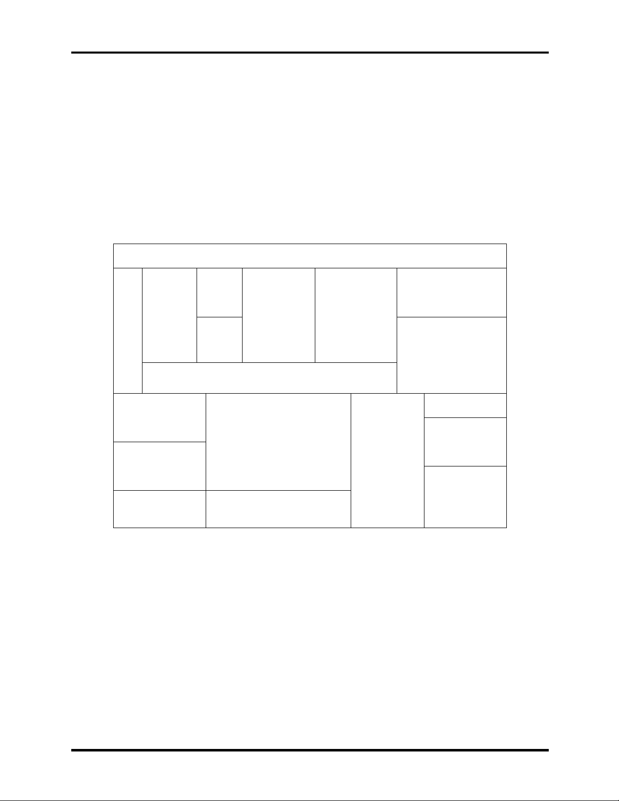
This section explains how to disassemble the computer and replace Field Replaceable Units
(FRUs). It may not be necessary to remove all the FRUs in order to replace one. The chart below
is a guide to which FRUs need to be removed in order to remove others. Always start by
removing the battery pack, next, optional items such as the optional PC Card, then follow the
chart downward removing only those FRUs necessary to reach the one you think is causing the
computer to operate improperly. Refer to the example on the following page.
Battery
HDD Wireless LAN unit
CPU
Expansion
memory
Keyboard
FDD
Optical media
drive
Display assembly
Top cover / power button
Display mask
System board
LED / button board
Modem
Fan Touch Pad
Speakers
FL inverter board
LCD module /
cable
Satellite A30 Series Maintenance Manual 4-1
Page 2
4 Replacement Procedures 4.1 General
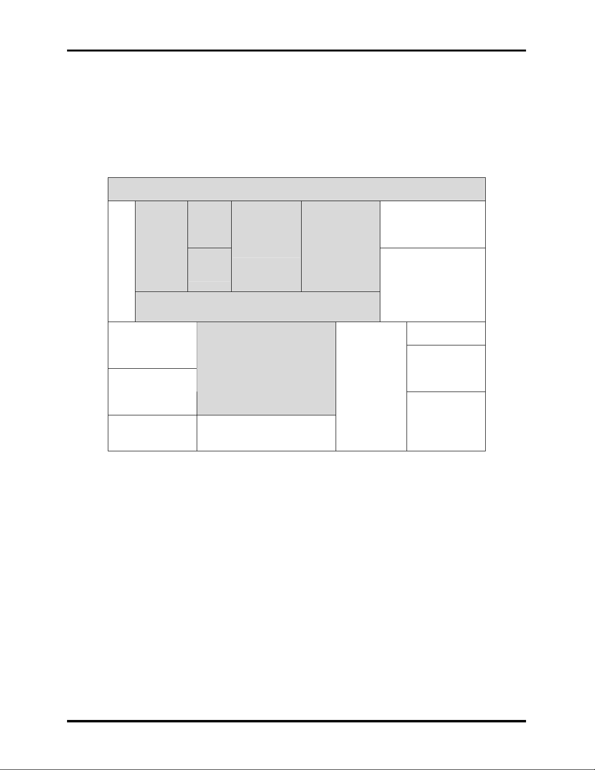
The example below shows FRUs to be removed before the LED / button board can be removed
and repaired or replaced. The LED / button board is overlapped by the top cover which must be
removed before the LED / button board can be reached. The top cover is in turn overlapped by
the expansion memory, HDD, FDD, keyboard and CD-ROM / DVD-ROM drive. Always starts
the disassembly process by removing the battery.
Battery
HDD Wireless LAN unit
CPU
Expansion
memory
Keyboard
FDD
Top cover / power button
Optical media
drive
Display assembly
Display mask
System board
LED / button board
Modem
Fan Touch Pad
Speakers
FL inverter board
LCD module /
cable
4-2 Satellite A30 Series Maintenance Manual
Page 3
4.1 General 4 Replacement Procedures
Safety Precautions
Before you begin disassembly, read the following safety precautions and observe them carefully
as you work.
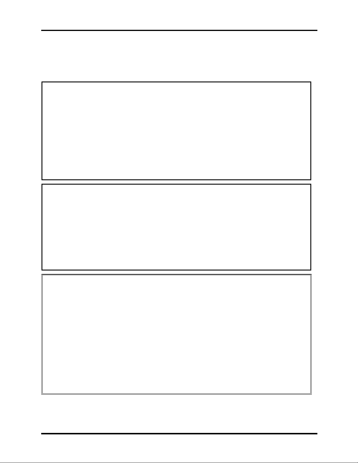
DANGER:
1. Always use the lithium ion battery pack or backup battery that is authorized by
Toshiba or compatible with the unit. Since other battery packs have different
specifications, they may be incompatible with the unit, and may burst or explode.
Heating or disassembling the battery pack could cause leakage of alkaline solution.
Throwing the battery pack into a fire could cause the battery pack to explode.
2. The power supply, FL inverter and other components carry high voltages. To avoid
the risk of electric shock when you need to turn on the power of a partially
disassembled computer to check its operation, be very careful not to touch
connectors or components. Also, do not disassemble individual components in firstlevel maintenance.
WARNING: To avoid the risk of electric shock or other injury:
1. Always turn the power off and disconnect the AC adaptor from the power source.
2. Remove any metal jewelry or accessories such as necklaces, bracelets, or rings.
Batteries in the computer retain an electrical charge so there is danger of electrical
shock even when the computer is disconnected from an AC power source.
3. Never work with wet or damp hands.
4. The computer contains sharp edges and corners: be careful not to injure yourself.
5. Make sure that all replacement components meet the specifications for the computer
and that all cables and connectors are securely fastened.
CAUTION: To avoid damage to the computer:
1. When you change a component, be sure the replacement component meets the required
specifications. Never use foreign parts.
2. Metal objects such as screws or paper clips which fall into the unit can cause a shortcircuit, fire, or other internal damage.
3. When assembling the computer, make sure you use the correct screws to secure the
various pieces in place. Screw sizes are listed in their corresponding figure. Make sure
all screws are securely fastened. Loose screws can cause short circuits, resulting in
heat, smoke, or fire.
4. Before removing an FRU or other component, make sure all cables to the component
have been disconnected.
5. If you use AC power, be sure to use the cable that came with the computer or one
recommended by Toshiba.
Satellite A30 Series Maintenance Manual 4-3
Page 4

4 Replacement Procedures 4.1 General
Before You Begin
Look over the procedures in this section before you begin disassembling the computer.
Familiarize yourself with the disassembly and reassembly steps. Begin each procedure by
removing the AC adaptor and the battery pack as instructed in section 4.2.
1. Do not disassemble the computer unless it is operating abnormally.
2. Use only the correct and approved tools.
3. Make sure the working environment is free from the following elements whether you are
using or storing the computer.
Dust and contaminates
Static electricity
Extreme heat, cold and humidity
4. Make sure the FRU you are replacing is causing the abnormal operation by performing
the necessary troubleshooting and diagnostics tests described in chapters 2 and 3 of this
manual.
5. Do not perform any operations that are not necessary and use only the described
procedures for disassembling and installing FRUs in the computer.
6. After removing parts from the computer, place them in a safe place away from the
computer so they will not be damaged and will not interfere with your work.
7. You will remove and replace many screws when you disassemble the computer. When
you remove screws, make sure they are placed in a safe place and identified with the
correct parts.
8. When assembling the computer make sure you use the correct screws to secure the
various pieces. Screw sizes are listed in their corresponding figures.
9. The computer contains many sharp edges and corners, so be careful not to injure yourself.
10. After you have replaced an FRU, make sure the computer is functioning properly by
performing the appropriate test on the FRU you have fixed or replaced.
4-4 Satellite A30 Series Maintenance Manual
Page 5

4.1 General 4 Replacement Procedures
Disassembly Procedures
The computer has two basic types of cable connectors:
Pressure Plate Connectors
Standard Pin Connectors
To disconnect a Pressure Plate connector, lift up the tabs on either side of the connector’s plastic
pressure plate and slide the cable out of the connector. To connect the cable to a Pressure Plate
connector, make sure the pressure plate is fully lifted and slide the cable into the connector.
Secure the cable in place by pushing the sides of the pressure plate down so the plate is flush
with the sides of the connector. Gently pull on the cable to make sure the cable is secure. If you
pull out the connector, connect it again making sure the connector’s pressure plate is fully lifted
when you insert the cable.
Standard pin connectors are used with all other cables. These connectors can be connected and
disconnected by simply pulling them apart or pushing them together.
Assembly Procedures
After you have disassembled the computer and fixed or repaired the problem that was causing the
computer to operate abnormally, you will need to reassemble the computer.
Install all the removed FRUs following the steps described in the corresponding sections in this
chapter.
While assembling the computer, remember the following general points:
Take your time, making sure you follow the instructions closely. Most problems arise
when you get in a hurry assembling the computer.
Make sure all cables and connectors are securely fastened.
Before securing the FRU or other parts, make sure that no cables will be pinched by
screws or the FRU.
Check that all latches are closed securely.
Make sure all the correct screws are used to secure all FRUs. Using the wrong screw
can either damage the threads on the screw or the head of the screw and may prevent
proper seating of an FRU.
After installing an FRU in the computer, confirm that the FRU and the computer are functioning
properly.
Satellite A30 Series Maintenance Manual 4-5
Page 6

4 Replacement Procedures 4.1 General
Tools and Equipment
The use of Electrostatic Discharge (ESD) equipment is very important for your safety and the
safety of those around you. Proper use of these devices will increase the success rate of your
repairs and lower the cost for damaged or destroyed parts. The following equipment is necessary
to disassemble and reassemble the computer:
One M2 Phillips screwdriver to remove and replace screws.
One T5 security screwdriver.
Tweezers, to lift out screws that you cannot grasp with your fingers.
ESD mats for the floor and the table you are working on.
ESD wrist strap or heel grounder.
Anti-static carpeting or flooring.
Air-ionizers in highly static sensitive areas.
4-6 Satellite A30 Series Maintenance Manual
Page 7
4.2 Battery 4 Replacement Procedures
4.2 Battery
Removing the Battery Pack
To remove the battery pack, follow the steps below.
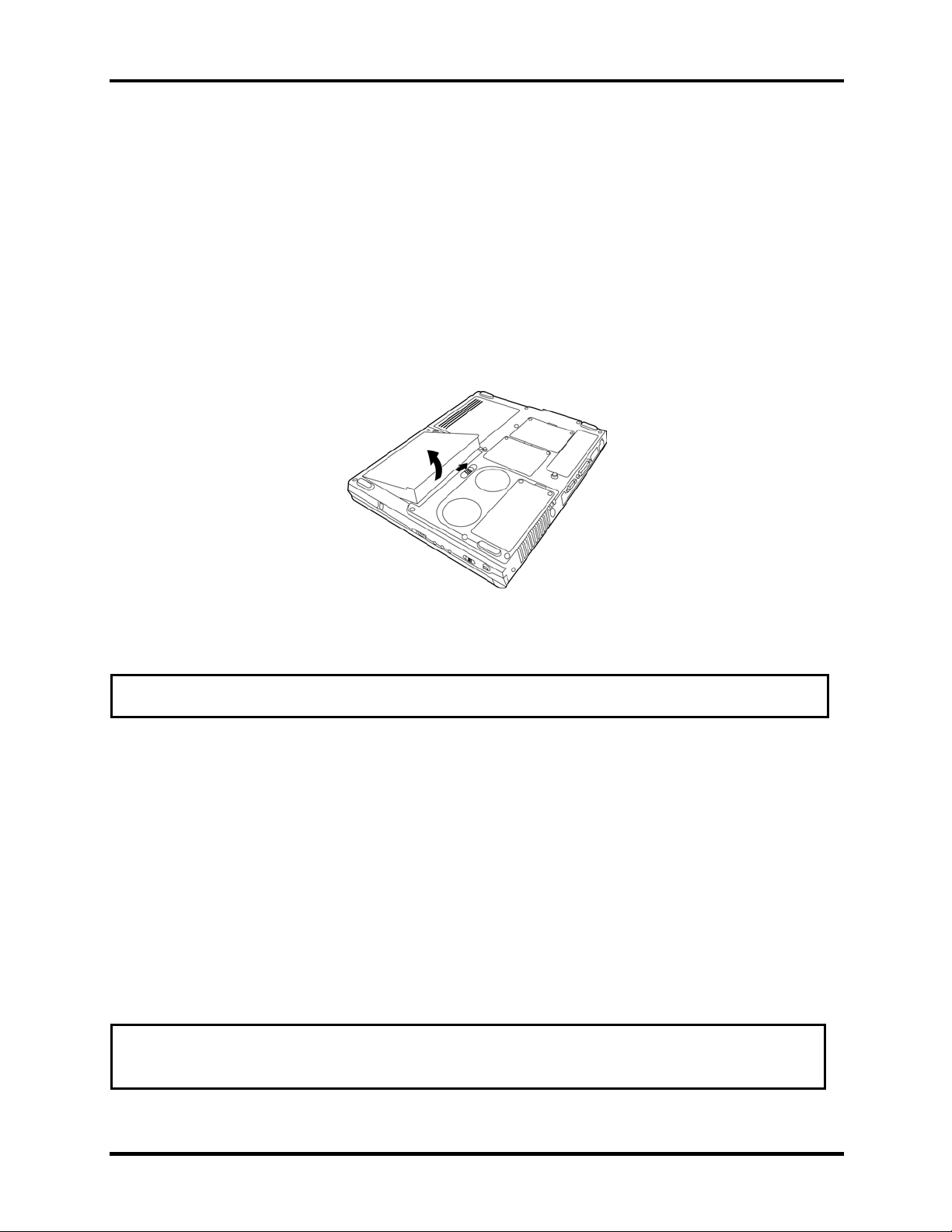
1. Turn the computer upside down with the front of the computer’s fan and rear ports
facing your body.
2. Slide the battery latch to the right to release it. The battery pack will pop up slightly
allowing you to lift it out.
Figure 4-1 Removing the battery
NOTE: For environmental reasons, please return spent battery packs to Toshiba.
Installing the Battery Pack
To install the battery pack, follow the steps below.
1. Turn the computer’s power off.
2. Disconnect all cables connected to the computer.
3. Hold the battery pack so that the label faces down and the connectors on the battery face
the connectors on the computer.
4. Gently press down. The battery latch clicks and automatically secures the battery pack
in position.
WARNING: The battery is a lithium ion battery and can explode if not properly replaced,
used, handled or disposed of. Use only batteries recommended by Toshiba as replacements.
Satellite A30 Series Maintenance Manual 4-7
Page 8
4 Replacement Procedures 4.3 PC Card
4.3 PC Card
Removing a PC Card
To remove a PC Card, follow the steps below.
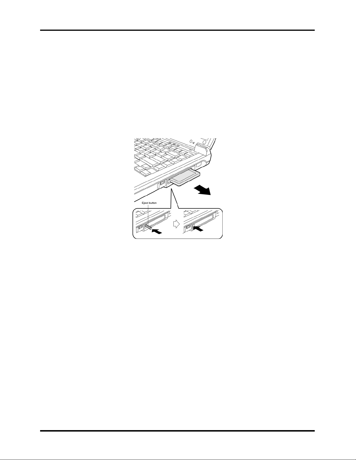
1. Push the eject button for the card you want to release. The button pops out when you
release it.
2. Push the eject button once more to pop the PC Card out slightly.
Figure 4-2 Popping out the eject button
3. Grasp the PC Card and remove it.
4. Push the eject button back into place, if necessary.
Installing the PC Card
To install the PC Card, follow the steps below.
1. Make sure the two eject buttons do not stick out.
2. Insert the PC Card and press gently to ensure a firm connection.
4-8 Satellite A30 Series Maintenance Manual
Page 9
4.4 Expansion Memory 4 Replacement Procedures
4.4 Expansion Memory
Removing the Expansion Memory
To remove the expansion memory, follow the steps below.
1. Turn the computer upside down.
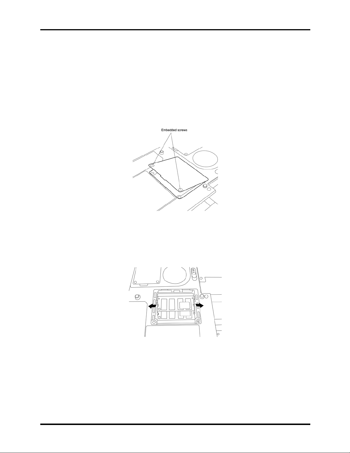
2. Remove the two embedded screws securing the expansion memory cover.
Figure 4-3 Removing expansion memory screws
3. Lift off the expansion memory cover.
4. Gently press out on the latches locking the expansion memory chip into slot A (the
bottom most one.) One end of the expansion memory will pop up.
Figure 4-4 Opening the expansion memory latches
Satellite A30 Series Maintenance Manual 4-9
Page 10
4 Replacement Procedures 4.4 Expansion Memory
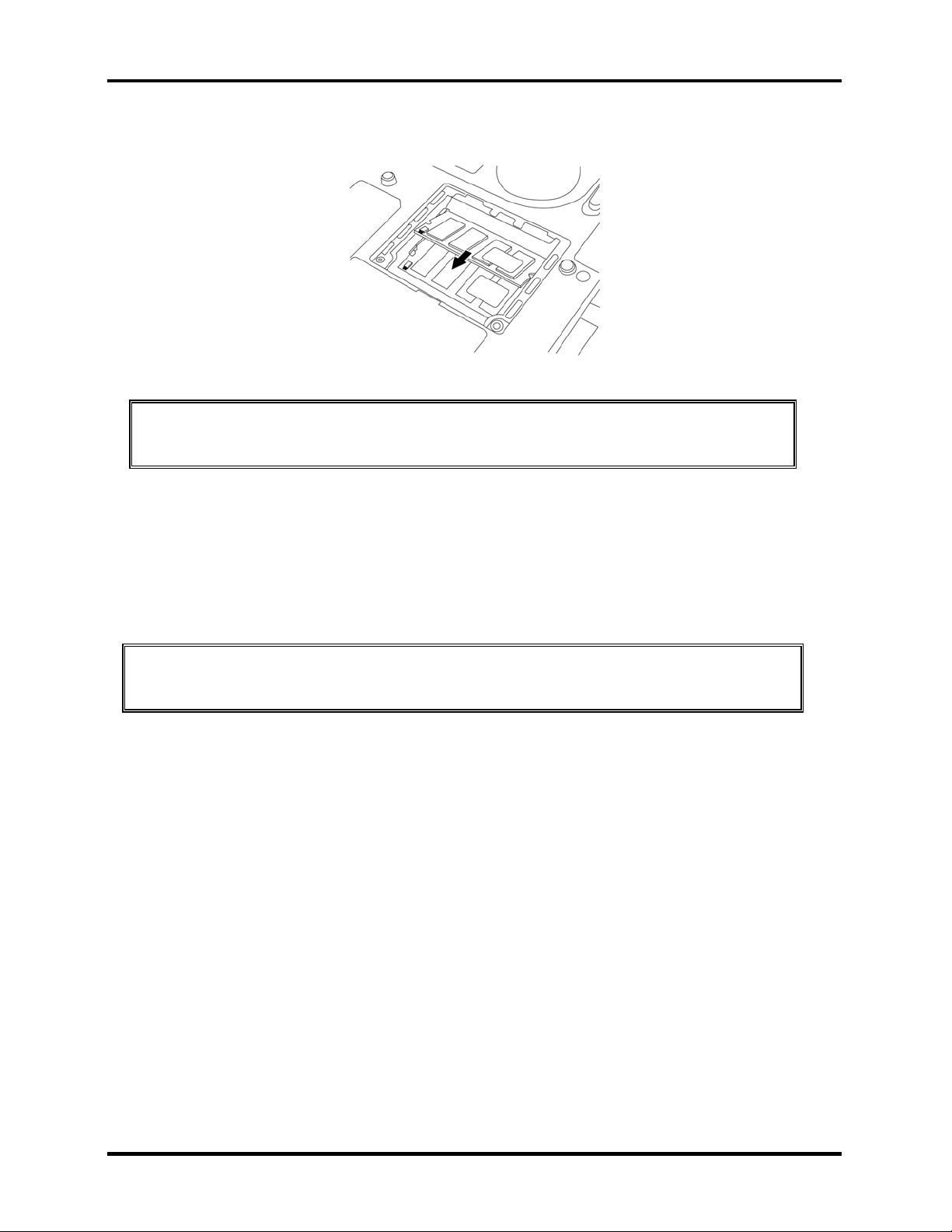
5. Grasp the expansion memory and pull it out.
Figure 4-5 Removing the expansion memory into the connector slot
CAUTION: Do not touch the connectors on the expansion memory or on the
computer. Debris on the connectors may cause memory access problems.
Installing the Expansion Memory
To install the expansion memory, follow the steps below.
1. Fit the expansion memory’s connectors into the computer’s connectors and press
carefully to ensure firm contact.
CAUTION: Do not touch the connectors on the expansion memory or on the computer.
Debris on the connectors may cause memory access problems.
2. Gently, push the expansion memory down until latches on either side engage the
expansion memory to hold it in place.
3. Seat the expansion memory cover in place and secure it with two embedded screws.
4-10 Satellite A30 Series Maintenance Manual
Page 11
4.5 HDD 4 Replacement Procedures
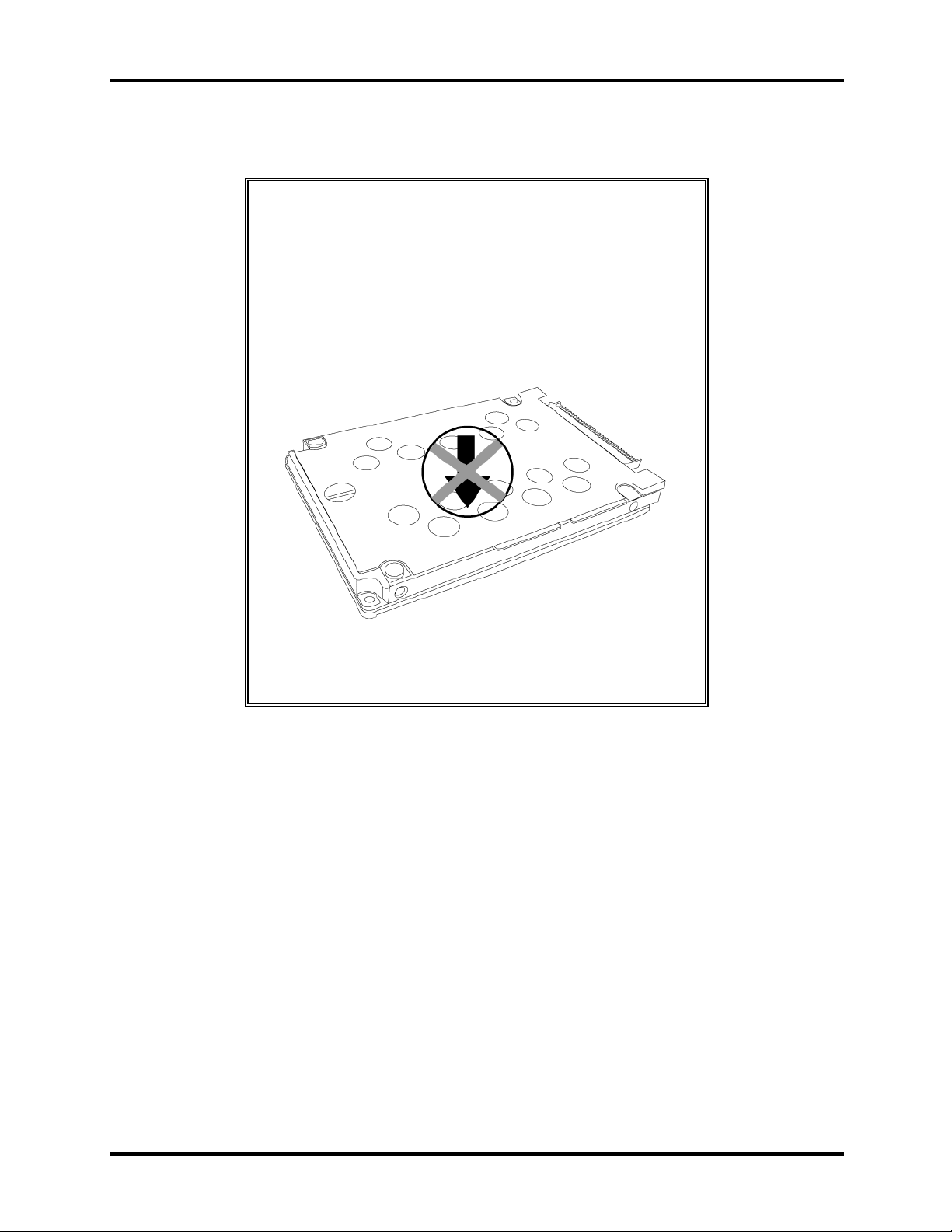
4.5 HDD
CAUTION: When handling the HDD, do not press the
top surface as shown by the arrow. Hold it by the sides.
Satellite A30 Series Maintenance Manual 4-11
Page 12
4 Replacement Procedures 4.5 HDD
Removing the HDD
To remove the HDD, follow the steps below.
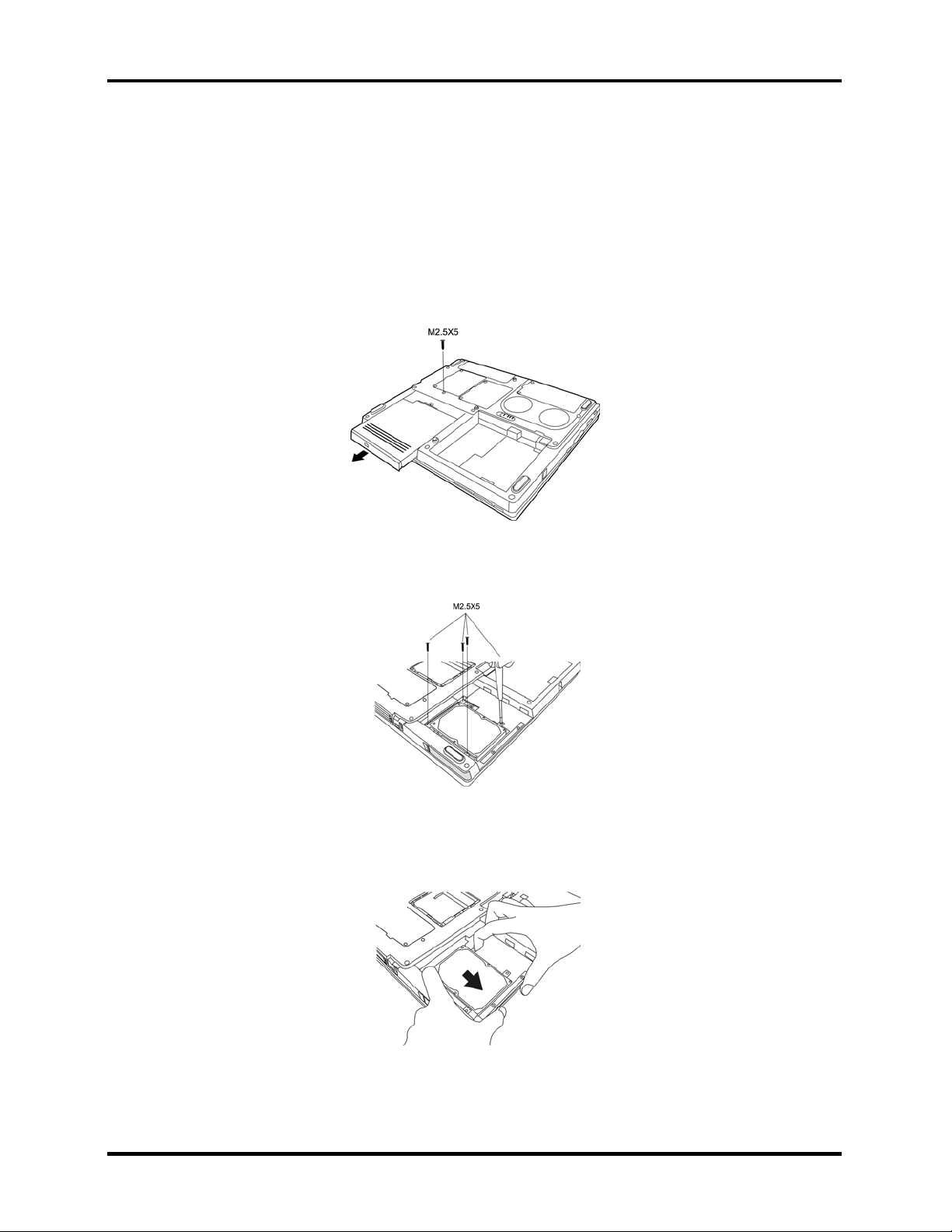
1. Turn the computer upside down with the optical media drive facing
your body.
2. Remove one M2.5x5 black screw and then remove the optical media drive.
Figure 4-6 Removing the optical media drive
3. Remove the four M2.5x5 black screws that secure the HDD to the computer.
Figure 4-7 Unscrewing the HDD
4. With two fingers, pull back on the HDD using the back brackets. The HDD slides out of
the connector socket inside the HDD bay.
Figure 4-8 Pulling the HDD out of the connector socket
4-12 Satellite A30 Series Maintenance Manual
Page 13
4.5 HDD 4 Replacement Procedures
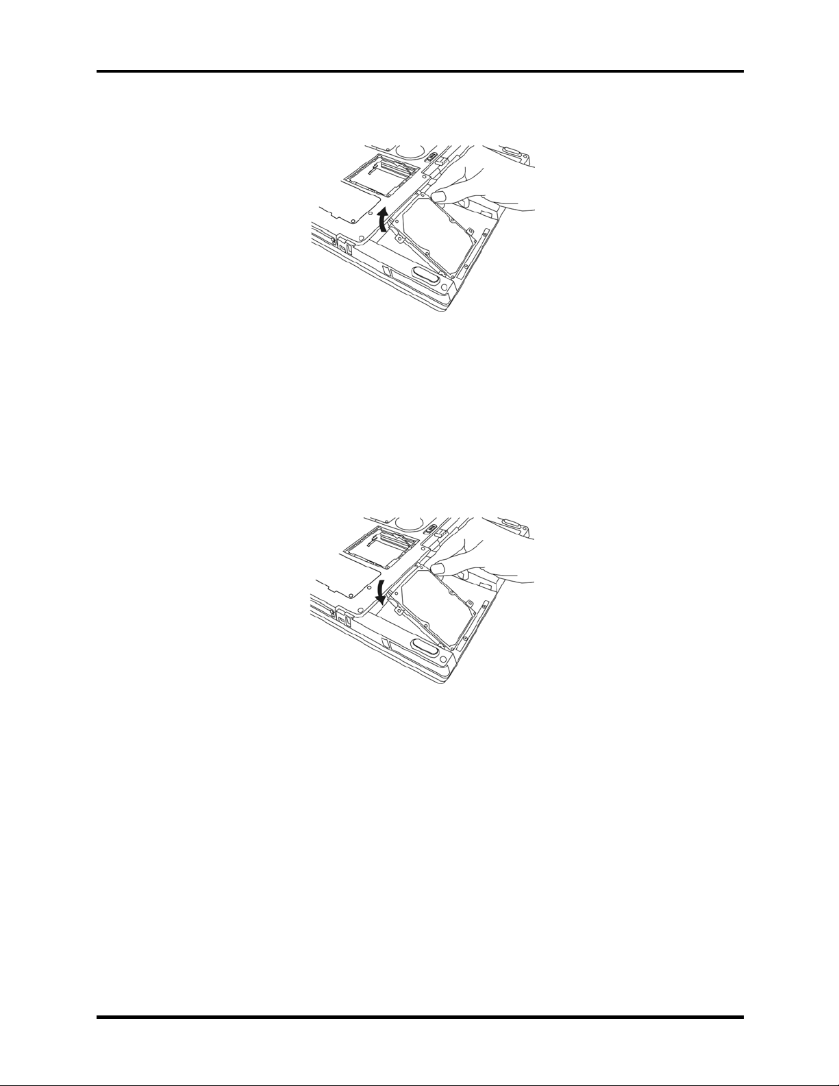
5. Gently pull the HDD out of the HDD bay.
Figure 4-9 Removing the HDD from the HDD bay
Installing the HDD
To install the HDD, follow the steps below.
1. Turn the computer upside down with the optical media drive facing your body.
2. Gently place the HDD in the HDD bay.
Figure 4-10 Inserting the HDD into the HDD bay
3. With two fingers, slide the HDD into the connector slot using the back brackets and until
it snaps into place.
4. Secure the HDD with four M2.5×5 black screws.
Satellite A30 Series Maintenance Manual 4-13
Page 14
4 Replacement Procedures 4.6 Keyboard
4.6 Keyboard
Removing the Keyboard
To remove the keyboard, follow the steps below.
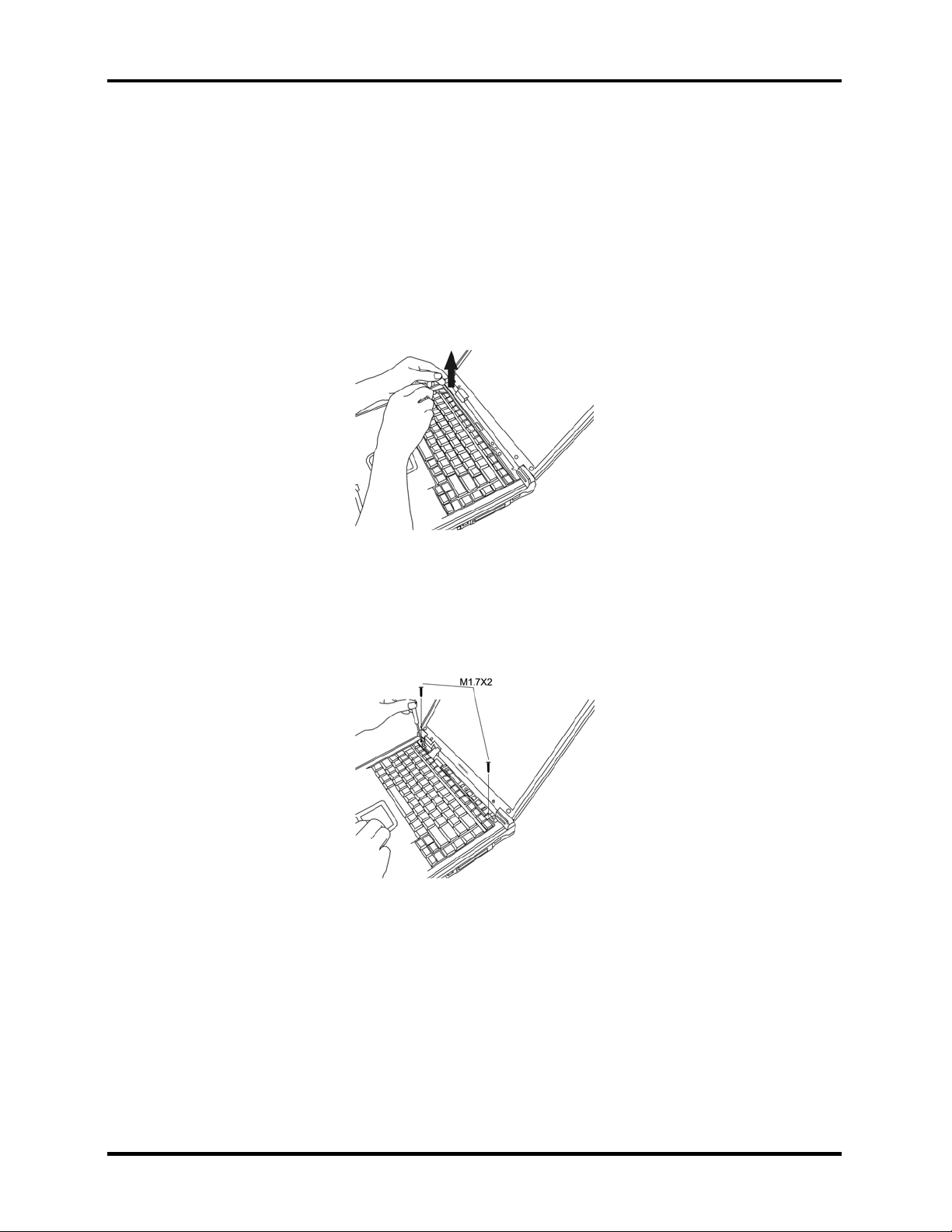
1. Open the display panel until it is almost horizontal.
2. Depress the F1 key on the back row of your keyboard and insert a thin tool into the
narrow hole beneath the strip cover.
Figure 4-11 Removing the strip cover
3. Use the tool to gently pry the strip cover away from the computer
4. Remove two M1.7x2 black screws from the top of the keyboard where they secure it to
the computer chassis.
Figure 4-12 Removing the keyboard screws
4-14 Satellite A30 Series Maintenance Manual
Page 15
4.6 Keyboard 4 Replacement Procedures
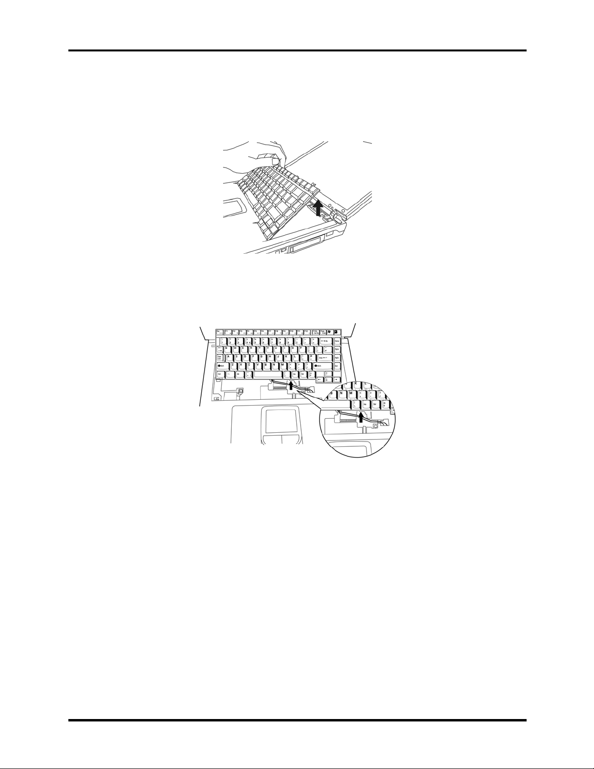
5. Gently pull the keyboard up from the top and then out. The bottom part of the keyboard
has 5 teeth that are inserted into notches in the chassis, so be sure not to break them off as
you remove the keyboard.
Figure 4-13 Removing the keyboard from the chassis
6. On the keyboard’s bottom side is a keyboard cable. Gently detach it by pulling in back
toward the display panel.
Figure 4-14 Disconnecting the keyboard cable
7. Remove the keyboard.
Installing the Keyboard
To install the keyboard, follow the steps below.
1. Turn the keyboard upside down on the palm rest and connect the keyboard cable to the
system board.
Satellite A30 Series Maintenance Manual 4-15
Page 16
4 Replacement Procedures 4.6 Keyboard
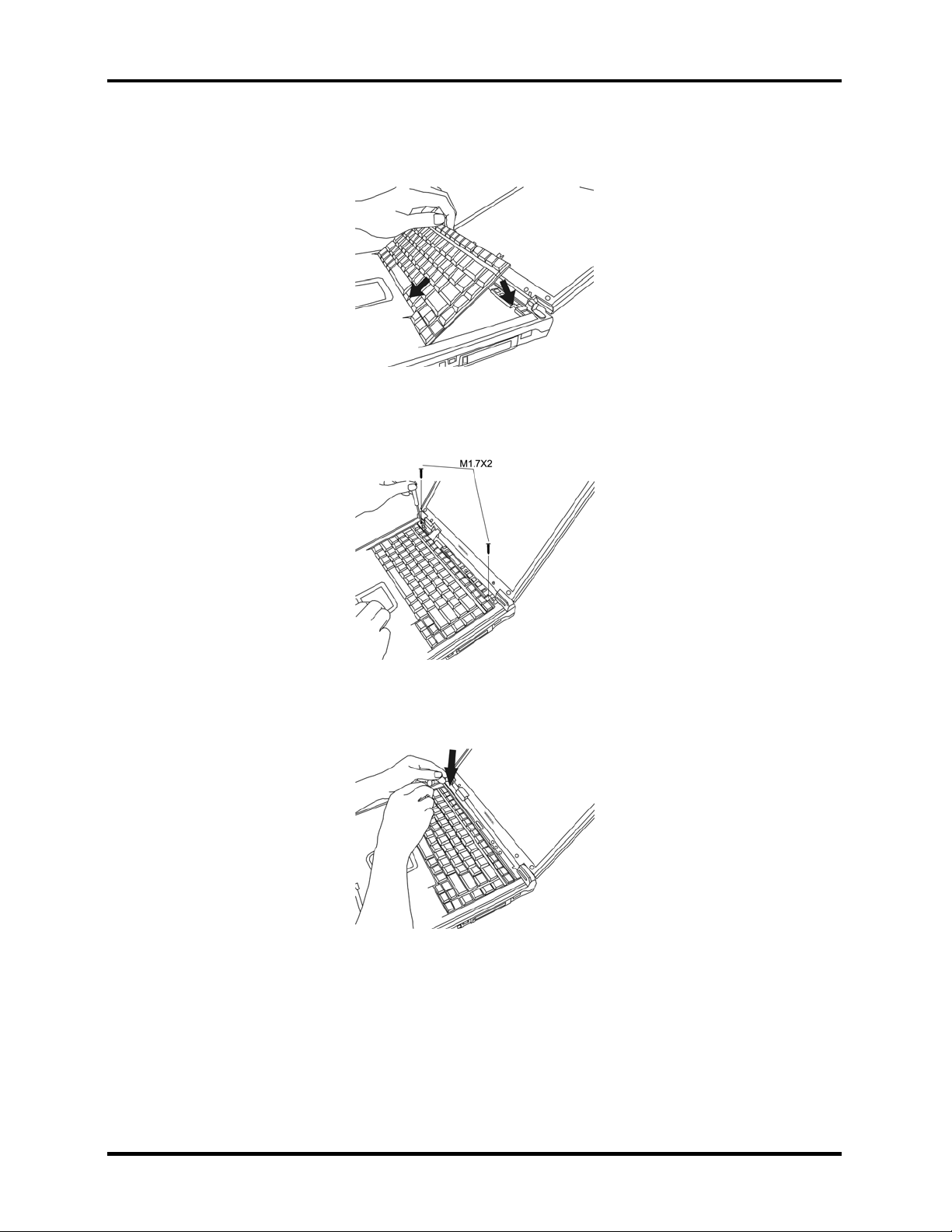
2. Turn the keyboard face up and set it in place. Ensure that the teeth at the bottom of the
keyboard match up with and are inserted into the notches in the chassis.
Figure 4-15 Inserting the keyboard
3. Secure the keyboard with two M1.7×2 black screws.
Figure 4-16 Securing the keyboard with screws
4. Replace the strip cover.
Figure 4-17 Replace the strip cover
4-16 Satellite A30 Series Maintenance Manual
Page 17

4.7 Wireless LAN Unit 4 Replacement Procedures
4.7 Wireless LAN Unit
Removing the Wireless LAN Unit
To remove the wireless LAN unit, follow the steps below.
1. Turn the computer upside down and loosen the two embedded screws.
2. Remove the wireless LAN module cover.
3. Disconnect the black and white wireless LAN connector cables.
Figure 4-18 Detaching the connector cables
4. Gently press out on the latches locking the wireless LAN unit into the slot. One end of
the wireless LAN unit pops up.
Figure 4-19 Pressing the wireless LAN unit latches
5. Grasp the end of the wireless LAN unit and pull it out.
CAUTION: Do not touch the connectors on the wireless LAN unit or on the
computer. Debris on the connectors may cause malfunction.
Satellite A30 Series Maintenance Manual 4-17
Page 18

4 Replacement Procedures 4.7 Wireless LAN Unit
Installing the Wireless LAN Unit
To install the wireless LAN unit, follow the steps below.
1. Fit the wireless LAN unit’s connectors into the computer’s connectors and press
carefully to ensure firm contact.
2. Gently, push the wireless LAN unit down until the latch engages the unit.
Figure 4-20 Pressing the wireless LAN unit into place
3. Attach ends of wireless LAN connector cables. The white aerial cable should be
attached to top-most connector (nearer the back side of the computer), the black aerial
cable to the bottom-most connector.
Figure 4-21 Attaching the wireless LAN connector cables
4. Restore the wireless LAN module cover.
CAUTION: Do not touch the connectors on the wireless LAN unit or on the
computer. Debris on the connectors may cause malfunction.
4-18 Satellite A30 Series Maintenance Manual
Page 19

4.8 Optical Media 4 Replacement Procedures
4.8 Optical Media
Removing the optical media drive
To remove the optical media drive, follow the steps below.
1. Turn the computer upside down with the optical media drive facing your body.
2. Remove one M2.5x5 black screw and then remove the optical media drive.
Figure 4-22
Removing the optical media drive
NOTE: You should not disassemble the optical media drive, as described below, unless
you are going to replace it.
3. Remove the two M2x3 silver bracket screws at the back of the optical media drive.
Figure 4-23 Removing the back screws
4. Remove the back bracket.
Figure 4-24 Removing the back bracket
Satellite A30 Series Maintenance Manual 4-19
Page 20

4 Replacement Procedures 4.8 Optical Media
5. Remove the four M2x3 black bracket screws on either side of the optical media drive.
Figure 4-25 Removing the side screws
6. Remove the optical media drive bracket.
Figure 4-26 Removing the optical media drive bracket
7. Insert a paper clip into the manual eject slot to open the optical media drive.
8. Insert the paper clip into the slot behind the front face’s left edge. This pops the front
face off.
Figure 4-27 Removing the front face
4-20 Satellite A30 Series Maintenance Manual
Page 21

4.8 Optical Media 4 Replacement Procedures
Installing the Optical Media
To install an optical media drive, follow the steps below.
1. Turn the computer upside down with the optical media drive bay facing
your body.
2. Slide the optical media drive into optical media drive bay, pushing it forward until it clicks
into place.
3. Secure the optical media drive with one M2.5x5 black screw
Satellite A30 Series Maintenance Manual 4-21
Page 22

4 Replacement Procedures 4.9 CPU
4
4.9 CPU
Removing the CPU
To remove the CPU, follow the steps below.
1. Turn the computer upside down and remove two M2.5×4 security screws securing the
CPU compartment cover.
Figure 4-28 Removing the CPU compartment cover screws
2. Remove the CPU compartment cover.
Figure 4-29 Removing the CPU compartment cover
4-22 Satellite A30 Series Maintenance Manual
Page 23

4.9 CPU 4 Replacement Procedures
3. Remove four M2.5×5 black screws securing the heat sink. They must be unscrewed in
catty-corner order (i.e. lower-left first, then upper right second, and so-on.)
Figure 4-30 Removing the heat sink screws
4. Remove the heat sink.
Figure 4-31 Removing the heat sink
CAUTION: If you remove the heat sink, you should use the CPU grease tool to remove
the grease on the CPU and heat sink. Reapply fresh grease before replacing the heat sink.
5. Turn the cam on the CPU socket with a flat-blade screwdriver so that the notch on the
cam is aligned with the “open” side of the CPU socket to unlock the CPU.
Figure 4-32 Unlocking the CPU cam
Satellite A30 Series Maintenance Manual 4-23
Page 24

4 Replacement Procedures 4.9 CPU
6. Gently lift out the CPU.
Figure 4-33 Removing the CPU
Installing the CPU
To install the CPU, follow the steps below.
CAUTION: If you remove the heat sink, you should use the CPU grease tool to remove
the grease on the CPU and heat sink. Reapply fresh grease before installing the heat sink.
1. Make sure that the notch on the cam is aligned with the open position.
Figure 4-34 Unlocking the CPU cam
2. Seat the CPU to align the triangle mark on the CPU with the upper right corner of the
socket if the front of the computer is facing your body. Make sure the alignment is exact
to avoid damaging pins on the CPU.
Figure 4-35 Aligning the CPU triangle
4-24 Satellite A30 Series Maintenance Manual
Page 25

4.9 CPU 4 Replacement Procedures
3. Press the CPU softly with your fingers and turn the cam on the CPU socket to the closed
position with a flat-blade screwdriver to secure the CPU.
4. Seat the heat sink over the CPU making sure that the heat sink is oriented so that the
two knobs in the CPU compartment secure it.
Figure 4-36 Inserting the heat sink
5. Secure the heat sink with four M2.5×5 black screws. The screws must be put tightened
in a catty- corner order (i.e. lower-left first, then upper right second, etc.)
Figure 4-37 Tightening the heat sink screws
6. Replace the CPU compartment cover.
Figure 4-38 Replacing the CPU compartment cover
7. Secure the CPU compartment cover with two M2.5×4 security screws.
Satellite A30 Series Maintenance Manual 4-25
Page 26

4 Replacement Procedures 4.10 Display Assembly
4.10 Display Assembly
Removing the Display Assembly
To remove the display assembly, first remove the battery and the wireless LAN module (or
simply disconnect its aerial cables first), then follow the steps below.
NOTE: If you have a wireless LAN card installed, you will have to disconnect the wireless
LAN connector wire before removing the display assembly. See section 4-7 for details.
1. Insert a thin tool into the hole on the strip cover and slide it to the right. The strip cover
will pop up allowing you to remove it.
Figure 4-39 Removing the strip cover
2. Remove two M2.5×5 black screws and slide the joint covers outwards and upward to
remove them. Note that you’ll have to push the display back until it rests at a 45° angle in
order to get the joint covers out completely
Figure 4-40 Removing the joint covers
3. Remove the keyboard as described in section 4-6, Removing the Keyboard.
4-26 Satellite A30 Series Maintenance Manual
Page 27

4.10 Display Assembly 4 Replacement Procedures
4. Remove one M1.7x2 black screws connecting the LCD cable to the chassis.
Figure 4-41 Detaching the LCD cable
5. Remove two M2.5x18 black screws on the top and one M2.5x8 black screw at the back
from each silver bracket holding the LCD display to the computer.
Figure 4-42 Removing the bracket screws
6. Gently lift the display assembly away from the computer’s chassis with the display in the
closed position.
Figure 4-43 Lifting the display away from the chassis
Satellite A30 Series Maintenance Manual 4-27
Page 28

4 Replacement Procedures 4.10 Display Assembly
Installing the Display Assembly
To install the display assembly, follow the steps below.
1. Seat the display assembly taking care not to crush to the LCD display cable.
Figure 4-44 Seating the display assembly
2. Feed the wireless LAN connector into the wireless LAN compartment.
Figure 4-45 Inserting the wireless LAN connector
3. Place computer upside down and attach the ends of the wireless LAN connector to the
wireless LAN unit.
4. Attach LCD display cable to connector on system board and secure with one
M1.7×2 screw.
Figure 4-46 Connecting the LCD cable
4-28 Satellite A30 Series Maintenance Manual
Page 29

4.10 Display Assembly 4 Replacement Procedures
5. Attach the joint covers by slipping them down and in, then insert two M2.5×5 black
screws to connect the display assembly to the chassis. Note that you’ll have to push the
display back until it rests at a 45° angle in order to get the joint covers in completely.
6. Attach the keyboard as described earlier.
7. Position strip cover and slide it to the left to lock it in position.
Satellite A30 Series Maintenance Manual 4-29
Page 30

4 Replacement Procedures 4.11 The Cover
4.11 The Cover
Removing the Cover
To remove the cover, follow the steps below.
1. Remove the battery, optical media drive, HDD, keyboard, and display assembly as
described in previous sections.
2. Remove the following eighteen screws from the bottom of the computer:
• Eight M2.5×18 black screws
• Two M2.5x8 black screws
• Two M2.5x3 black screws in the battery bay
• Two M2.5x5 silver screws in the optical media bay
• Four hexagonal screws for the video monitor port and the parallel port.
A: M 2.5 x 8 B: M 2.5 x 18 C: M 2.5 x 5 D: M 2.5 x 3
Figure 4-47 Removing the screws securing the bottom of the cover
3. Turn the computer over.
4-30 Satellite A30 Series Maintenance Manual
Page 31

4.11 The Cover 4 Replacement Procedures
4. Remove the following five screws from the top of the computer:
• Two M2.5×18 black screws
• Two M2.5 ×5 black screws
• One M2.5 ×8 black screws
A: M 2.5 x 18 B: M 2.5 x 5 C: M 2.5 x 8
Figure 4-48 Removing the screws securing the top of the cover
5. Remove the following cables:
• TouchPad FPC cable
• LED/control button FFC cable
• Speaker cable
Figure 4-49 Removing the cables
6. Lift the top cover from the computer’s chassis.
Figure 4-50 Removing the cover
Satellite A30 Series Maintenance Manual 4-31
Page 32

4 Replacement Procedures 4.11 The Cover
Installing the Cover
To install the top cover and display assembly, follow the steps below.
1. Seat the cover on the computer’s chassis.
2. Attach the following cables:
• TouchPad FPC cable
• LED/control button FFC cable
• Speaker cable
Figure 4-51 Attaching the cables
3. Connect the following five screws from the top of the computer:
• Two M2.5×18 black screws
• Three M2.5 ×5 black screws
• One M2.5 ×8 black screws
A: M 2.5 x 18 B: M 2.5 x 5 C: M 2.5 x 8
Figure 4-52 Connecting the screws securing the top of the cover
4. Attach the keyboard and display assembly as described in previous sections.
5. Turn the computer over.
6. Connect the following eighteen screws from the bottom of the computer:
• Eight M2.5×18 black screws
• Two M2.5x8 black screws
• Two M2.5x3 black screws in the battery bay
• Two M2.5x5 silver screws in the optical media bay
4-32 Satellite A30 Series Maintenance Manual
Page 33

4.11 The Cover 4 Replacement Procedures
• Four hexagonal screws for the video monitor port and the parallel port.
A: M 2.5 x 8 B: M 2.5 x 18 C: M 2.5 x 5 D: M 2.5 x 3
Figure 4-53 Removing the screws securing the bottom of the cover
7. Insert the optical media, the battery and the HDD as described in previous sections.
Satellite A30 Series Maintenance Manual 4-33
Page 34

4 Replacement Procedures 4.12 System Board
4.12 System Board
Removing the System Board
To remove the system board, follow the steps below.
1. Remove the computer cover as described in a previous section.
2. Place the computer upside down so the optical media and battery bays are lying face
down.
3. Remove two M2×4 silver screws and two M2.5x5 black screws securing the module
support. Slide the module support towards the system board then remove.
Figure 4-54 Removing the module support
4. Remove two M2.5x5 black screws securing the system board to the chassis.
Figure 4-55 Removing the system board screws
4-34 Satellite A30 Series Maintenance Manual
Page 35

4.12 System Board 4 Replacement Procedures
5. Gently remove the system board by pulling it away from the back of the chassis, out and
up ward. The rear parallel port, TV-Out port and USB ports may stick a little to the
chassis on the way out, but resist the urge to pull too hard.
Figure 4-56 Removing the system board
Installing the System Board
To install the system board, follow the steps below.
1. Seat the system board, making sure to ease the ports into their openings on the chassis
and cover.
2. Secure the system board with two M2.5x5 black screws.
Figure 4-57 Removing the system board screws
3. Secure the module support in place with two M2×4 silver screws and two M2.5x5 black
screws.
Figure 4-58 Securing the module support
Satellite A30 Series Maintenance Manual 4-35
Page 36

4 Replacement Procedures 4.13 Modem
4.13 Modem
Removing the Modem
To remove the modem, follow the steps below.
1. Remove the system board, as described in a previous section.
2. Remove two M2.5x5 black screws securing the modem to the system board.
Figure 4-59 Removing the system board
3. Disconnect the modem cable from the modem module.
4. Gently lift the modem module from the system board.
Installing the Modem
To install the modem, follow the steps below.
1. Place the modem module on the system board.
2. Connect the modem cable to the modem module.
3. Secure two M2.5x5 black screws connecting the modem to the system board.
4. Reinstall the system board, as described in a previous section.
4-36 Satellite A30 Series Maintenance Manual
Page 37

4.14 Fan 4 Replacement Procedures
4.14 Fan
Removing the Fan
To remove the fan, follow the steps below.
1. Remove all of the modules and the system board as described in previous sections.
2. Place the system board so that the fan is on the bottom. Remove two M2×5 silver
screws securing the fan.
Figure 4-60 Removing the screws that secure the fan to the system board
3. Remove the Northbridge heat sink cover, which also secures the fan. To do so, you
must loosen 3 embedded screws.
Figure 4-61 Removing the Northbridge screws
4. Turn the system board over.
Satellite A30 Series Maintenance Manual 4-37
Page 38

4 Replacement Procedures 4.14 Fan
5. Disconnect the fan power cables.
Figure 4-62 Disconnecting the fan power cables
6. Remove the fan.
Figure 4-63 Removing the fan
Installing the Fan
To install the fan, follow the steps below.
1. Seat the fan on the system board.
2. Secure it with two M2×5 silver screws.
3. Secure the Northbridge heat sink cover, which also holds the fan place. To do so, you
must tighten 3 embedded screws.
4. Connect the fan power cables to the system board.
4-38 Satellite A30 Series Maintenance Manual
Page 39

4.15 LED/Button Board 4 Replacement Procedures
4.15 LED/Button Board
Removing the LED/Button Board
To remove the LED/button board, follow the steps below.
1. Remove all of the modules and the computer cover as described in previous sections.
2. Place top cover upside down.
3. Remove one M2.5x3 black screw from the LED/button board mounting bracket.
Figure 4-64 Removing the LED/button board mounting bracket screw
4. Slide the mounting bracket a little to the right, if the back of the cover faces you, and
then lift it and the board out.
Figure 4-65 Removing the mounting bracket and the board
5. Remove three M2x3 black screws from the face of the LED/button board.
Figure 4-66 The LED/button board
Satellite A30 Series Maintenance Manual 4-39
Page 40

4 Replacement Procedures 4.15 LED/Button Board
Installing the LED/Button Board
To install the LED/button board, follow the steps below.
1. Seat the LED/button board on the mounting bracket and secure with three
M2×3 screws.
2. Position LED/button board and mounting bracket inside the top cover and secure it
with one M2.5×3 screws.
3. Attach LED/button FFC cable to the system board.
4. Restore all the modules and cover pieces as described in previous sections.
4-40 Satellite A30 Series Maintenance Manual
Page 41

4.16 TouchPad 4 Replacement Procedures
4.16 TouchPad
Removing the TouchPad
To remove the TouchPad, follow the steps below.
1. Remove the computer’s modules and top cover as described in previous sections.
2. Pull the TouchPad FPC cable out from behind the silver system board shield.
Figure 4-67 Removing the TouchPad cable
3. Remove two M2.5 x3 black screws from the TouchPad bracket.
Figure 4-68 Detaching the TouchPad bracket screws
Satellite A30 Series Maintenance Manual 4-41
Page 42

4 Replacement Procedures 4.16 TouchPad
4. With LCD/Button board away from you, slide the TouchPad bracket toward you to
disconnect it from its cover seat.
Figure 4-69 Removing the TouchPad board and bracket
5. Lift out the TouchPad along with the TouchPad bracket.
Installing the TouchPad
To install the TouchPad, follow the steps below.
1. With top cover upside down, place TouchPad in position and cover it with TouchPad
cover. Slide TouchPad cover back to lock it in position.
2. Feed TouchPad FPC cable through silver system board shield on the top cover.
3. Attach two M2.5×3 screws to secure TouchPad board.
4-42 Satellite A30 Series Maintenance Manual
Page 43

4.17 Speakers 4 Replacement Procedures
4.17 Speakers
Removing the Speakers
To remove the speakers, follow the steps below.
1. Place the top cover upside down and remove the TouchPad bracket and board as
described in previous sections of the manual.
2. Slide the speaker wires out from under the LCD/Button board bracket.
Figure 4-70 Removing the speaker wires
3. Detach the LED/button FFC cable and the speaker cable from the adhesive glue
binding them to the cover so you can slide the speaker wires out from under them.
4. Remove one M2.5x5 black screw from each speaker.
Figure 4-71 Unscrewing the right speaker
5. Remove the speakers.
Satellite A30 Series Maintenance Manual 4-43
Page 44

4 Replacement Procedures 4.17 Speakers
Installing the Speakers
To install the speakers, follow the steps below.
1. Place the top cover upside down and remove the TouchPad bracket and board as
described in previous sections of the manual.
2. Detach the LED/button FFC cable and the speaker cable from the adhesive glue
binding them to the cover so you can slide the speaker wires under them.
3. Seat each speaker. The speaker closest to the speaker cables goes on the right.
4. Secure each speaker with one M2.5×5 screw.
5. Reattach the LED/button FFC cable and the speaker cable to the adhesive glue on the
cover so you can slide the speaker wires under them.
6. Slide the speaker wires under the LCD/Button board bracket.
7. Reattach the TouchPad bracket and board as described in previous sections of the
manual.
4-44 Satellite A30 Series Maintenance Manual
Page 45

4.18 Display Mask 4 Replacement Procedures
4.18 Display Mask
Removing the Display Mask
To remove the display mask, follow the steps below.
1. On each bottom corner, remove one mask seal by the hinge to expose one screw
securing the display mask.
Figure 4-72 Removing the mask seals
2. On each bottom corner, remove one M2.5×8 screw that was covered by the mask seal.
Figure 4-73 Removing two screws securing the display mask
Satellite A30 Series Maintenance Manual 4-45
Page 46

4 Replacement Procedures 4.18 Display Mask
3. A total of 22 snaps secure the display mask. Carefully insert your fingers between the
display mask and the LCD panel and pry open the snaps.
Figure 4-74 Removing the display mask
Installing the Display Mask
To install the display mask, follow the steps below.
1. Seat the display mask and secure the snaps on each side.
2. Secure the display mask with two M2.5×8 screws at the hinges.
3. Attach two mask seals to cover the screws.
4-46 Satellite A30 Series Maintenance Manual
Page 47

4.19 FL Inverter Board 4 Replacement Procedures
4.19 FL Inverter Board
Removing the FL Inverter Board
To remove the FL inverter board, follow the steps below.
1. Remove one strip of tape securing the HV cable and two strips of tape to uncover two
screws securing the FL inverter board.
Figure 4-75 Removing the tape
2. Remove the two M2×3 black screws securing the FL inverter board.
Figure 4-76 Removing the FL screws
3. Carefully lift up the FL inverter board and disconnect the FL FPC and the HV cable
from the FL inverter board.
Figure 4-77 Detaching the FL FPC and HV cable
Satellite A30 Series Maintenance Manual 4-47
Page 48

4 Replacement Procedures 4.19 FL Inverter Board
Installing the FL Inverter Board
To install the FL inverter board, follow the steps below.
1. Connect the FL FPC and HV cable to the FL inverter board.
Figure 4-78 Connecting the FL FPC and HV cable
2. Seat the FL inverter board and secure it with two silver M2×3 screws.
Figure 4-79 Securing the FL screws
3. Secure the HV cable with one strip of tape.
4. Cover the two screws securing the FL inverter board with tape.
Figure 4-80 Connecting the tape
4-48 Satellite A30 Series Maintenance Manual
Page 49

4.20 LCD Module 4 Replacement Procedures
4.20 LCD Module
Removing the LCD Module
To remove the LCD module, follow the steps below.
1. Remove the FL inverter board as described in previous sections.
2. Remove one M2×3 screw to release LCD cable.
Figure 4-81 Freeing the LCD cable
3. Remove six M2×3 screws securing the LCD module.
Figure 4-82 Removing the module screws
Satellite A30 Series Maintenance Manual 4-49
Page 50

4 Replacement Procedures 4.20 LCD Module
4. Lift the LCD module out of the LCD cover.
Figure 4-83 Removing the LCD module
5. Disconnect the LCD cable from LCD connector.
Figure 4-84 Removing the LCD cable
6. Remove eight M2×3 screws securing the LCD bracket (the number of bracket screws
may vary on different models: 14” models have four, while 15” models have eight).
Figure 4-85 Removing the LCD bracket screws
4-50 Satellite A30 Series Maintenance Manual
Page 51

4.20 LCD Module 4 Replacement Procedures
7. Remove LCD bracket.
Figure 4-86 Removing the LCD bracket
NOTE: If the LCD module malfunctions, remove the LCD cable and LCD bracket. Then
replace the whole LCD module unit.
Installing the LCD Module
To install the LCD module, follow the steps below.
1. Connect the LCD cable to the LCD connector on the back of the LCD module.
Figure 4-87 Attaching the LCD cable
2. Secure LCD cable with a stripe of tape.
3. Secure the LCD bracket to the LCD module with eight M2×3 screws (the number of
bracket screws may vary on different models).
Satellite A30 Series Maintenance Manual 4-51
Page 52

4 Replacement Procedures 4.20 LCD Module
4. Position the LCD module in place.
Figure 4-88 Positioning the LCD module
5. Secure the LCD module with eight M2×3 screws.
Figure 4-89 Fastening the LCD bracket screws
6. Secure LCD cable with one M2×3 screw.
Figure 4-90 Securing the LCD cable
4-52 Satellite A30 Series Maintenance Manual
 Loading...