

Page 1
Publish Date: 99/06/18
M-FSA29016a.pdf
.
.
BSI No.: A29016
Subject:
Change the Service Manual (country settings)
Model: TF610
Category Field Application Unit
Modification/Correction of
Service Manual
Factory Application:
To be applied immediately Operator's Manual/Service
CONTENT
1. Document No.
For TAIS
For except TAIS
Add the step for the country setting in the service manual.
E0-26146
E0-26150
.
.
.
.
Manual
See attached pages ii, 3-1, 3-31, 3-32, 8-17 and 8-18.
2. Reason for Change
Correct the service manual.
(The country code should be set when the ROM or Main PBA is replaced.)
Attached Files
Page 2

TF610
4.2.4 TEL line cord ............................................................................................... 3-14
4.2.5 Recording paper.......................................................................................... 3-15
4.2.6 Recording Paper Exit Tray/Document Exit Tray/Document Tray Wire.......... 3-19
4.2.7 One Touch Dial Index Labels ....................................................................... 3-21
4.3 Printer Driver ............................................................................................................. 3-22
4.3.1 Computer Requirements.............................................................................. 3-22
4.3.2 Connecting the Facsimile to Your PC...........................................................3-23
4.3.3 Installing the Printer Driver Software ........................................................... 3-24
4.3.4 Removing the Printer Driver Software......................................................... 3-25
5. Hardware Options ................................................................................................ 3-26
5.1 Remarks before starting work ................................................................................... 3-26
5.2 Attaching hardware options ....................................................................................... 3-27
5.2.1 Memory PBA ............................................................................................... 3-27
6. Connect the Machine to Po wer and Telephone Line.........................................3-29
7. Country Setting....................................................................................................3-31
8. Memory Clear .......................................................................................................3-31
9. Remarks on Moving the Machine .......................................................................3-32
Chapter 4 Function Settings
1. User Function Settings..........................................................................................4-1
1.1 Select Options ............................................................................................................. 4-2
1.2 Ringer Volume [MENU], [ENTER], [ ↓] ........................................................................ 4-2
1.3 Speaker Volume [MENU], [ENTER], [↓], [↓] ............................................................... 4-3
1.4 Polling Security Code [MENU], [ENTER], [↓], [↓], [↓]................................................. 4-3
1.5 System Password [MENU], [ENTER],[↓],[↓],[↓]......................................................... 4-4
1.6 Remote Access Code [MENU], [ENTER],[↓],[↓],[↓] .................................................. 4-4
1.7 Date and Time [MENU], [ENTER], [↑], [↑], [↑]............................................................ 4-5
1.8 Terminal ID Number [MENU], [ENTER], [↑], [↑] ......................................................... 4-5
1.9 Terminal ID Name [MENU], [ENTER], [↑]................................................................... 4-6
2. Service Parameter Settings................................................................................... 4-7
2.1 Setting Procedure........................................................................................................4-7
2.2 Parameters Table ......................................................................................................... 4-8
Chapter 5 Mechanical Description
1. Basic Components ................................................................................................ 5-1
2. Transmission Section............................................................................................5-2
2.1 Actions of Transmission Section................................................................................. 5-2
2.2 Components of Transmission Section ......................................................................... 5-4
2.2.1 Document Guide Area ................................................................................... 5-4
ii SERVICE MANUAL
Page 3
Chapter 3 Installation
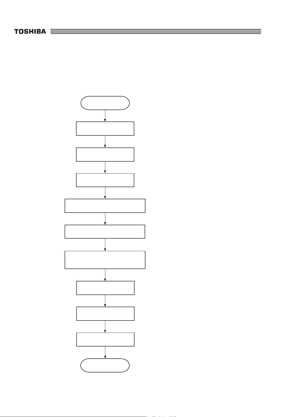
1. Installation Procedure
Follow the procedure below to install a TF610.
Start
Preparation (Refer to page 3-2)
TF610
Unpacking
Accessories
Attaching the accessories
Attaching the hardware option
Connect the machine to power
and telephone line
Country Setting (Refer to page 3-31)
(Refer to page 3-4)
(Refer to page 3-6)
(Refer to page 3-7)
(Refer to page 3-26)
(Refer to page 3-29)
Memory Clear (Refer to page 3-31)
Function setting (Refer to page 4-1)
End
SERVICE MANUAL 3-1 Chapter 3
Page 4

7. Country Setting
At the time of installation, be sure to perform the country setting for each country .
Procedure:
(1) Select the dial k ey number from the tab le below . (The ROM type can be confirmed by the ROM
version No.)
(2) Turn the power on while pressing and holding the dial key selected in (1) and the [START] key at
the same time.
(3) confirm that the country name (example: US) displayed on the LCD is correct.
Key 0123456789*#
ROM type
EU PT DE GB CH NL BE AT S E NO DK FI IT
US US CA AU SG HK TW
FR FR
TF610
ES PT DE GB CH NL BE AT SE NO DK ES IT
NOTE: The country setting should always be performed when the ROM or Main PBA is
replaced.
8. Memory Clear
At the time of installation, be sure to perform a full memory clear to initialize the machine before
entering the function setup procedures. After the memory clear , go on to whate ver prog ramming procedures that are necessary.
Procedure:
(1) Press the [1], [3], and [8] keys at the same time in the standby status.
(2) Enter the 4-digit password "5656", then pressing the [START] key.
(3) Select the "INDIVIDUAL TEST" by using the [MENU/ ↑ ] key then pressing the [ENTER] key.
(4) Select the "SVC INSTALL" by using the [MENU/ ↑ ] or [ ↓ ] key then pressing the [START]
key. (Refer to Chapter 11: 1.2.9, "Service Installation Clear" page 11-10.)
SERVICE MANUAL 3-31 Chapter 3
Page 5

TF610
9. Remarks on Moving the Machine
Procedure:
(1) Disconnect the power cord.
(2) Remo v e the TEL line cord and the external telephone set.
(3) Remove the process unit from the machine. (Refer to page 3-9.) Pack the process unit with
the packing materials. Do not ship the machine with a process unit installed; otherwise, severe
toner dusting may result !
(4) Remove the accessories or attachments from the machine (refer to page 3-6.) and pack them
in a carton.
(5) Secure the top cover and the operation panel with tape so that they do not open.
NOTE: The process unit should be kept with this machine, or it should be discarded. DO
NOT use this process unit in another machine or poor image quality may result.
DO NOT put another process unit into this machine (unless it is new) or poor
image quality may result.
Chapter 3 3-32 SERVICE MANUAL
Page 6

Installation
(1) Attach the PCB holder, three washers, and two spacers to the main PBA. Install the main PBA
with the three screws, two mount screws, and four nuts.
(2) Push the interface cover into the PCB holder to install.
(3) Align the main PBA with the guide of the printer block, and secure the main PBA with four
screws.
(4) Connect all the connectors (CN1, CN2, CN3, CN4, CN5, CN8, CN9, CN10, CN11, CN12,
CN13, CN15, CN16, CN52).
(5) Install the NCU PBA. (Refer to 2.2.1, "NCU PBA.")
(6) Install the upper cover. (Refer to 2.1.3, "Top Cover and Upper Cover.")
(7) Install the oper ation panel assembly. (Refer to 2.1.2, "Operation Panel Assembly.")
(8) Install the cradle co ver or cradle dumm y cover. (Refer to 2.1.1, "Cradle Co ver or Cradle Dumm y
Cover .")
(9) Perform the country setting. (Ref er to Chapter 3: 7. "Country Setting.")
(10) After installation, connect the power cord, and execute and confirm the following:
TF610
• Using the option report and telephone number lists printed out prior to replacing the main
PBA, program the replacement PBA.
• Reset all counter data in memory write mode using the decimal data provided on the options
report. (Refer to Chapter 11: 1.8, "Memory Write.")
• Total TX pages address : 80282-80284
• Total RX pages address : 80285-80287
• Total copy pages address : 80288-8028A
• Total print counter : 80290-80292
• Perform the memor y test and margin settings. (Refer to Chapter 11: 1.2.2, "Memory Test"
and 1.2.14, "Margin Settings.")
SERVICE MANUAL 8-17 Chapter 8
Page 7

TF610
2.2.3 ROM
Before disassembling or reassembling, be sure to refer to 1, "Before Disassembling or Reassembling."
Removal
(1) Remove the one screw from the rear cover and remove the rear cover.
(2) Remove the ROM from the main PBA.
ROM
Rear cover
7-14.eps
Fig. 8-2-13
Installation
(1) Insert the ROM into the socket on the main PBA in a correct orientation.
(2) Align the two hooks located on the upper part of the rear cover with the upper cov er , and secure
the rear cover with the one screw.
(3) Perform the memory test. (Ref er to Chapter 11: 1.2.2, "Memory Test.")
(4) Perform the country setting. (Ref er to Chapter 3: 7. "Country Setting.")
Chapter 8 8-18 SERVICE MANUAL
 Loading...