

Page 1

6F3B0250
CTi Automation - Phone: 800.894.0412 - Fax: 208.368.0415 - Web: www.ctiautomation.net - Email: info@ctiautomation.net
PROGRAMMABLE CONTROLLER
PROSEC
USER’S MANUAL
----
Basic Hardware and Function
UM-TS01
T1 / T1S
***
-E001
----
TOSHIBA CORPORATION
Page 2

Important Information
CTi Automation - Phone: 800.894.0412 - Fax: 208.368.0415 - Web: www.ctiautomation.net - Email: info@ctiautomation.net
Misuse of this equipment can result in property damage or human injury.
Because controlled system applications vary widely, you should satisfy yourself
as to the acceptability of this equipment for your intended purpose.
In no event will Toshiba Corporation be responsible or liable for either indirect
or consequential damage or injury that may result from the use of this equipment.
No patent liability is assumed by Toshiba Corporation with respect to use of
information, illustrations, circuits, equipment or examples of application in this
publication.
Toshiba Corporation reserves the right to make changes and improvements to this
publication and/or related products at any time without notice. No obligation shall be
incurred other than as noted in this publication.
This publication is copyrighted and contains proprietary material. No part of this book
may be reproduced, stored in a retrieval system, or transmitted, in any form or by any
means ¾ electrical, mechanical, photocopying, recording, or otherwise ¾ without
obtaining prior written permission from Toshiba Corporation.
6F3B0250
© TOSHIBA Corporation 1995. All rights reserved
PROSEC and TOSLINE are registered trademarks of TOSHIBA Corporation.
IBM is a registered trademark of International Business Machines Corporation.
MS-DOS and Windows are registered trademarks of Microsoft Corporation.
Publication number: UM-TS01
***
-E001
1st edition December 1995, 4th edition February 1998
Page 3

6F3B0250
CTi Automation - Phone: 800.894.0412 - Fax: 208.368.0415 - Web: www.ctiautomation.net - Email: info@ctiautomation.net
CE Marking
The Programmable Cont r oller PROSEC T1 and T1S (hereafter called T1/T1S) complies with the
requirements of t he EMC Directive 89/336/EEC and Low Voltage Directive 72/23/EEC under the
condition of use according to the instructions described in this manual.
The contents of the conformity are shown below.
Application of EMC : 89/336/EEC (as amended by 91/263/EEC and 92/31/EEC)
Council Directive LVD : 72/23/EEC (as amended by 93/68/EEC)
Manufacture’s Name : Toshiba Corporation, Fuchu Works
Address : 1, Toshiba-Cho
Fuchu-shi
TOKYO 183
Japan
declares, that the product
Product Name : Programmable Controller , T1 Series
Model Number : TDR116*6S, TAR116*6S, TDR116*3S
TDR128*6S, TAR128*6S, TDR128*3S
TDR140*6S, TAR140*6S, TDR140*3S
TDR140S6S, TAR140S6S, TDR140S3S
conforms to the following Product Specifications:
EMC
Radiated Interference : EN 55011 Group 1 Class A
Mains Interference : EN 55011 Group 1 Class A
Radiated Susceptibility : ENV50140
Conducted RFI Susceptibility : ENV50141, IEC100-4-6.
Electrostatic Discharge : IEC1000-4-2
Electrical Fast Transient : IEC1000-4-4
LVD : EN61131-2:1995 3.10 Dielectric Properties
4. Mechanical Requirements
Supplementary information :
(1) Included Handy Programmer THP911A*S.
(2) Included each type of associated input/output unit in a typical configuration.
(3) Product must be installed in accordance with manufacturers instructions
Basic Hardware and Function
1
Page 4

6F3B0250
CTi Automation - Phone: 800.894.0412 - Fax: 208.368.0415 - Web: www.ctiautomation.net - Email: info@ctiautomation.net
UL/c-UL Listing
The Programmable Cont r oller PROSEC T1 and T1S (hereafter called T1/T1S) are UL/c-UL listed
as shown below.
UL and c-UL Listing
File Number : E95637
Product Name : Programmable Controller , T1 Series
Product Covered : Main Unit
TDR116*6S, TAR116*6S, TDR116*3S,
TDR128*6S, TAR128*6S, TDR128*3S,
TDR140*6S, TAR140*6S, TDR140*3S,
TDR140S6S, TAR140S6S, TDR140S3S
Option Card
TDI116*BS, TDD116*BS, TDO116*BS,
TAD121*BS, TAD131*BS, TDA121*BS, TDA131*BS,
TFR112*BS
Expansion Unit
TDR132E*S, TAR132E*S
Expansion Rack
TBU152**S, TBU154**S
Peripherals
TRM102**S, TCU111**S, THP911A*S
UL and c-UL Listing For Use in Hazardous Locations
File Number : E184034
Product Name : Programmable Controller , T1 Series
Product Covered : Main Unit
TDR116*6S, TAR116*6S, TDR116*3S,
TDR128*6S, TAR128*6S, TDR128*3S,
TDR140*6S, TAR140*6S, TDR140*3S,
Locations Class : Class I, Division 2, Groups A, B, C, D
Important Notice : 1. THIS EQUIPMENT IS SUITABLE FOR USE IN CLASS I,
DIVISION 2, GROUPS A, B, C, D OR NON-HAZARDOUS
LOCATIONS ONLY.
2. WARNING - EXPLOSION HAZARD - SUBSTITUTION OF
COMPONENTS MAY IMPAIR SUITABILITY FOR CLASS I,
DIVISION 2.
3. WARNING - EXPLOSION HAZARD - DO NOT DISCONNECT
EQUIPMENT UNLESS POWER HAS BEEN SWITCHED OFF
OR THE AREA IS KNOWN TO BE NON-HAZARDOUS.
T1/T1S User’s Manual
2
Page 5

6F3B0250
CTi Automation - Phone: 800.894.0412 - Fax: 208.368.0415 - Web: www.ctiautomation.net - Email: info@ctiautomation.net
Safety Precautions
This manual is prepared for users of Toshiba’s Programmable Controller T1/T1S.
Read this manual thoroughly before using the T1/T1S. Also, keep this manual and related manuals
so that you can read them anytime while the T1/T1S is in operation.
General Information
1. The T1/T1S has been designed and manufactured for use in an industr ial environment.
However, the T1/T1S is not intended to be used for systems which may endanger human
life. Consult Toshiba if you intend t o use the T1/T1S for a special applicat ion, such as
transportation machines, medical apparat us, aviation and space systems, nuclear
controls, submarine systems, etc.
2. The T1/T1S has been manufactured under strict quality control. However, to keep safety
of overall automated system, fail-safe systems should be considered outside the T1/T1S.
3. In installation, wiring, operation and maintenance of the T1/T1S, it is assumed that the
users have general knowledge of industrial elect r ic cont r ol system s.
If this product is handled or operat ed im pr operly, electrical shock, fire or dam age to this
product could result.
4. This manual has been written for users who are f am iliar with Prog rammable Controllers
and industrial control equipment. Cont act Toshiba if you have any questions about this
manual.
5. Sample programs and circuits described in this manual are provided for explaining the
operations and applications of the T1/T1S. You should test completely if you use them as
a part of your application system.
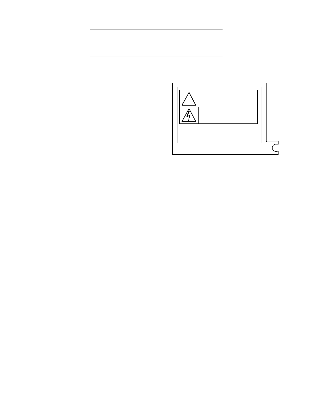
Hazard Classifications
In this manual, the following two hazard classifications are used to explain the safety
precautions.
!
WARNING
!
CAUTION
Even a precaution is classified as CAUTION, it may cause serious results depending on the
situation. Observe all the safety precautions described on this manual.
Indicates a potentially hazardous situation which, if not avoided, could
result in death or serious injury.
Indicates a potentially hazardous situation which, if not avoided, may
result in minor or moderate injur y. I t m ay also be used to aler t
against unsafe practices.
Basic Hardware and Function
3
Page 6

Safety Precautions
CTi Automation - Phone: 800.894.0412 - Fax: 208.368.0415 - Web: www.ctiautomation.net - Email: info@ctiautomation.net
Installation:
!
CAUTION
1. Excess temperature, humidity, vibration, shock s, or dusty and corrosive gas
environment can cause electrical shock, fire or malfunction. Install and use the T1/T1S
and related equipment in the environment described in this manual.
2. Improper installation directions or insufficient installation can cause fir e or t he units to
drop. Install the T1/T 1S and r elated equipment in accordance with the instructions
described in this manual.
3. Turn off power before installing or removing any units, modules, r acks or terminal
blocks. Failure to do so can cause electrical shock or dam age to the T1/T1S and
related equipment.
6F3B0250
4. Entering wire scraps or other foreign debris into to the T1/T 1S and r elated equipment
can cause fire or malfunction. Pay att ention to prevent entering them into the T1/T1S
and related equipment during inst allat ion and wiring.
5. Turn off power immediat ely if the T1/T1S or related eq uipm ent is emitting smoke or
odor. Operation under such situation can cause fire or electrical shock. Also
unauthorized repairing will cause fire or serious accidents. Do not attempt to repair.
Contact Toshiba for repairing.
Wiring:
!
CAUTION
1. Turn off power before wiring to minimize the risk of electrical shock.
2. Exposed conductive parts of wire can cause electrical shock. Use crimp-style terminals
with insulating sheath or insulating tape to cover the conductive parts . Also close t he
terminal covers securely on the terminal blocks when wiring has been completed.
3. Operation without grounding may cause electrical shock or malfunction. Connect the
ground terminal on the T1/T1S to the system ground.
4. Applying excess power voltage to the T1/T1S can cause explosion or fire. Apply power
of the specified rating s descr ibed in t he manual.
5. Improper wiring can cause fire, electr ical shock or malfunction. Obser ve local
regulations on wiring and grounding.
T1/T1S User’s Manual
4
Page 7

Safety Precautions
CTi Automation - Phone: 800.894.0412 - Fax: 208.368.0415 - Web: www.ctiautomation.net - Email: info@ctiautomation.net
Operation:
!
WARNING
1. Configure emergency stop and safety interlocking circuits out side t he T1/T1S.
Otherwise, malfunction of t he T1/T1S can cause injury or serious accidents.
!
CAUTION
2. Operate the T1/T1S and t he r elated modules with closing the terminal covers. Keep
hands away from terminals while power on, to avoid the risk of electrical shock.
3. When you attempt to perform force outputs, RUN/HALT controls, etc. during operation,
carefully check for safety.
6F3B0250
4. Turn on power to the T1/T1S before turning on power to the loads. Failure to do so may
cause unexpected behavior of the loads.
5. Do not use any modules of the T1/T1S for the purpose other than specified. This can
cause electrical shock or injury.
6. Do not modify the T1/T1S and r elat ed equipment in hardware nor software. This can
cause fire, electrical shock or injury.
7. Configure the external circuit so that the external 24 Vdc power required for t r ansistor
output circuits and power to the loads are switched on/off simultaneously.
Also, turn off power to the loads before turning of f power to the T1/T1S.
8. Install fuses appropriate to t he load cur rent in the external circuits for t he outputs.
Failure to do so can cause fire in case of load over-cur r ent .
9. Check for proper connections on wires, connector s and m odules. Insufficient contact
can cause malfunction or damage to t he T1/T1S and related equipment .
Basic Hardware and Function
5
Page 8

Safety Precautions
CTi Automation - Phone: 800.894.0412 - Fax: 208.368.0415 - Web: www.ctiautomation.net - Email: info@ctiautomation.net
Maintenance:
!
CAUTION
1. Turn off power before removing or replacing units, modules, terminal blocks or wires.
Failure to do so can cause electrical shock or damag e t o the T1/T1S and related
equipment.
2. When you remove both input and out put terminal blocks with wires for maintenance
purpose, pay attention to prevent inserting them upside down.
3. Do not insert your finger into t he expansion rack’s ventilation hole during power on.
This can cause electrical shock.
6F3B0250
4. Do not disassemble the T1/T1S because ther e ar e hazardous voltag e par ts inside.
5. Perform daily checks, periodical checks and cleaning to maintain the system in normal
condition and to prevent unnecessary troubles.
6. Check by referring “T r oubleshooting” section of this manual when operating
improperly. Contact Toshiba for repairing if t he T1/T1S or related eq uipm ent is failed.
Toshiba will not guarantee proper operation nor safety for unauthorized repairing.
7. The contact reliability of t he out put relays will reduce if the switching exceeds the
specified life. Replace the unit or module if exceeded.
T1/T1S User’s Manual
6
Page 9
Safety Label
CTi Automation - Phone: 800.894.0412 - Fax: 208.368.0415 - Web: www.ctiautomation.net - Email: info@ctiautomation.net
The safety label as shown on the right is
attached to the power terminal of the
T1/T1S.
Remove the mount paper before wiring.
Peel off the label fr om the mount paper
and stick it near the power terminals
where it can be readily seen.
Contact Toshiba if the label is damaged.
Safety Precautions
CAUTION
!
Do not touch terminals
while power on.
Hazardous voltage can shock , bur n or c ause death.
Do not touch terminals while power on.
Read related manual thoroughly for safety.
Stick this seal on uni t or near unit.
Take off this sheet before wiring.
6F3B0250
Basic Hardware and Function
7
Page 10

About This Manual
CTi Automation - Phone: 800.894.0412 - Fax: 208.368.0415 - Web: www.ctiautomation.net - Email: info@ctiautomation.net
About This Manual
This manual has been prepared for first-time users of Toshiba’s Programmable Controller
T1 and/or T1S to enable a full under standing of the configuration of the equipment, and to
enable the user to obtain the maximum benefit s of the equipment.
This manual introduces the T1 and T1S, and explains the system configuration,
specifications, installation and wiring for T1/T1S’s basic hardware. This manual provides
the information for designing T1/T1S user program, such as the internal operation, memory
configuration, I/O allocation and programming instructions. Information for maintenance
and troubleshooting are also provided in this manual.
The specifications of the option cards, expansion units, and I/O modules, and how to use
them, are explained in the separate manual. Read the T1/T1S User’s Manual - Expansion
I/O - when using the option cards, expansion units, and/or I/O modules.
The T1/T1S’s computer link function and T1S’s multi-purpose communication functions are
covered by the separate manual. Read the T1/T1S User ’s Manual - Comm unicat ion
Function - for details.
6F3B0250
Inside This Manual
This manual consists of 10 main sections and an appendix.
Section 1 outlines the T1/T1S configuration. To fully understand the T1/T1S, it is important
to read this section carefully. Sections 2, t o 4 descr ibe the hardware used in designing
external circuits and panels. Sections 5 to 7 are mainly concerned with software. Section 8
explains the T1/T1S’s special I/O functions. Sections 9 and 10 describe the maintenance
procedure for the T1/T1S, to ensure safe operation and long service life.
Related Manuals
The following related manuals are available for T1/T1S. Besides this manual, read t he
following manuals for your better under st anding.
T1/T1S User’s Manual - Basic Hardware and Function -
T1/T1S User’s Manual - Expansion I/O T1/T1S User’s Manual - Communication Function T-Series Handy Programmer (HP911) Operation Manual
T-Series Program Development System (T-PDS) User’s Manual
NOTE
Other than the listed above, some T1 related manuals for special I/O modules
and data transmission modules are available. Contact Toshiba for more
information.
(this manual)
T1/T1S User’s Manual
8
Page 11

Terminology
CTi Automation - Phone: 800.894.0412 - Fax: 208.368.0415 - Web: www.ctiautomation.net - Email: info@ctiautomation.net
The following is a list of abbreviations and acronyms used in this m anual.
6F3B0250
About This Manual
s
mmmm
ASCII
AWG
BCC
CCW
CPU
CW
EEPROM
H
I/O
LED
LSB
ms
MSB
PWM
RAM
ROM
Vac
Vdc
microsecond
American Standard Code For Infor m at ion I nt erchange
American W ir e Gage
Block Check Code
Counter-Clockwise
Central Processing Unit
Clockwise
Electrically Erasable Programmable Read O nly Memory
hexadecimal (when it appears in front of an alphanumer ic st r ing)
Input/Output
Light Emitting Diode
Least Significant Bit
millisecond
Most Significant Bit
Pulse Width Modulation
Random Access Memory
Read Only Memory
AC voltage
DC voltage
Basic Hardware and Function
9
Page 12

Contents
CTi Automation - Phone: 800.894.0412 - Fax: 208.368.0415 - Web: www.ctiautomation.net - Email: info@ctiautomation.net
Contents
6F3B0250
Safety Precautions
About This Manual
1. System Configuration
1.1 Introducing the T1 and T1S ................................................................ 14
1.2 Features .............................................................................................. 16
1.3 System configuration .......................................................................... 19
1.4 I/O expansion ...................................................................................... 20
1.5 Components ........................................................................................ 22
1.5.1 Basic unit ......................................................................................... 22
1.5.2 Option cards .................................................................................... 28
1.5.3 Expansion rack ................................................................................ 29
1.5.4 I/O modules ..................................................................................... 30
1.5.5 Expansion unit ................................................................................. 31
1.5.6 Options ............................................................................................ 32
1.6 Computer link system ........................................................................ 33
1.7 T1S communication function .............................................................. 34
1.8 Real-time data link system ................................................................. 36
1.9 Peripheral tools .................................................................................. 37
2. Specifications
..................................................................................
..................................................................................
....................................................................
..................................................................................
13
41
3
8
2.1 General specifications ........................................................................ 42
2.2 External dimensions ........................................................................... 43
2.3 Functional specifications .................................................................... 46
2.4 I/O specifications ................................................................................ 48
2.4.1 T1-16 ............................................................................................... 48
2.4.2 T1-28 ............................................................................................... 52
2.4.3 T1-40/T1-40S .................................................................................. 56
3. I/O Application Precautions
3.1 Application precautions for input signals ............................................ 62
3.2 Application precautions for output signals .......................................... 65
4. Installation and Wiring
4.1 Environmental conditions ................................................................... 68
4.2 Installing the unit ................................................................................. 69
4.3 Wiring terminals .................................................................................. 71
4.4 Grounding ........................................................................................... 76
4.5 Power supply wiring ............................................................................ 78
4.6 I/O wiring ............................................................................................ 80
..........................................................
...................................................................
61
67
T1/T1S User’s Manual
10
Page 13

6F3B0250
CTi Automation - Phone: 800.894.0412 - Fax: 208.368.0415 - Web: www.ctiautomation.net - Email: info@ctiautomation.net
Contents
5. Operating System Overview
5.1 Operation modes ................................................................................ 82
5.2 About the built-in EEPROM ................................................................ 84
5.3 Scanning ............................................................................................. 87
6. Programming Information
6.1 Devices and registers ......................................................................... 92
6.2 Index modification ............................................................................... 104
6.3 Real-time clock/calendar .................................................................... 106
6.4 I/O allocation ....................................................................................... 107
6.5 T1S memory mode setting ................................................................. 109
6.6 User program configuration ................................................................ 110
6.6.1 Main program .................................................................................. 112
6.6.2 Sub-program #1 .............................................................................. 113
6.6.3 Timer interrupt program .................................................................. 113
6.6.4 I/O interrupt programs ..................................................................... 114
6.6.5 Subroutines .................................................................................... 115
6.7 Programming language ...................................................................... 116
6.8 Program execution sequence ............................................................ 117
6.9 On-line debug support functions ........................................................ 118
6.10 Password protection ........................................................................... 121
.........................................................
.............................................................
81
91
7. Instructions
7.1 List of instructions .............................................................................. 124
7.2 Instruction specifications .................................................................... 134
8. Special I/O Functions
8.1 Special I/O function overview ............................................................. 268
8.2 Variable input filter constant .............................................................. 272
8.3 High speed counter ............................................................................ 273
8.3.1 Single phase up-counter ................................................................. 273
8.3.2 Single phase speed-counter ............................................................ 275
8.3.3 Quadrature bi-pulse counter ............................................................ 277
8.4 Interrupt input function ........................................................................ 280
8.5 Analog setting function ....................................................................... 282
8.6 Pulse output function .......................................................................... 283
8.7 PWM output function .......................................................................... 285
9. Maintenance and Checks
9.1 Precautions during operation ............................................................. 288
9.2 Daily checks ........................................................................................ 289
9.3 Periodic checks ................................................................................... 290
9.4 Maintenance parts ............................................................................... 291
......................................................................................
....................................................................
..............................................................
123
267
287
Basic Hardware and Function
11
Page 14

Contents
CTi Automation - Phone: 800.894.0412 - Fax: 208.368.0415 - Web: www.ctiautomation.net - Email: info@ctiautomation.net
6F3B0250
10. Troubleshooting
10.1 Troubleshooting procedure ................................................................ 294
10.1.1 Power supply check ......................................................................... 295
10.1.2 CPU check ....................................................................................... 296
10.1.3 Program check ................................................................................. 296
10.1.4 Input check ....................................................................................... 297
10.1.5 Output check .................................................................................... 298
10.1.6 Environmental problem .................................................................... 299
10.2 Self-diagnostic items .......................................................................... 300
Appendix
A.1 List of models and types ..................................................................... 306
A.2 Instruction index ................................................................................. 309
.........................................................................................................
..............................................................................
293
305
T1/T1S User’s Manual
12
Page 15

Section 1
CTi Automation - Phone: 800.894.0412 - Fax: 208.368.0415 - Web: www.ctiautomation.net - Email: info@ctiautomation.net
System Configuration
6F3B0250
1.1 Introducing the T1 and T1S, 14
1.2 Features, 16
1.3 System configuration, 19
1.4 I/O expansion, 20
1.5 Components, 22
1.6 Computer link system, 33
1.7 T1S Communication function, 34
1.8 Real-time data link system, 36
1.9 Peripheral tools, 37
Basic Hardware and Function
13
Page 16

1. System Configuration
CTi Automation - Phone: 800.894.0412 - Fax: 208.368.0415 - Web: www.ctiautomation.net - Email: info@ctiautomation.net
1.1 Introducing the T1 and T1S
The T1 Series are compact, block style, high-performance programmable controllers
with a range of 16 to 328 input and output points.
The T1 Series are available in two versions, T1 and T1S. T he T1S is an enhanced
version against the standard T1.
The figure below shows the T1 Series line-up. The T1 Series consists of the total 12
types.
T1 Seri es T1 T1-16 T1-MDR 16
6F3B0250
T1-MAR16
T1-MDR16D
T1-28 T1-MDR28
T1-MAR28
T1-MDR28D
T1-40 T1-MDR40
T1-MAR40
T1-MDR40D
T1S T1-40S T1-MDR40S
T1-MAR40S
T1-MDR40SD
I/O points:
The T1 Series are available in four models, T1-16, T1-28, T1- 40 and T1-40S. Each
model has the following I/O points.
T1-16 T1-28 T1-40 T1-40S
Input
Output
Expansion
The T1-16 and T1-28 are fixed I/O non-expandable controllers.
The T1-40 and T1-40S, however, provides additional flexibility. They are expandable in
three ways, option cards, expansion rack and expansion unit.
The T1-40/T1-40S can hold two option cards. These are approximately 1/2 the size of a
credit card. Also, the T1-40/ T1-40S can be connected to either one expansion rack or
one expansion unit. The expansion rack (2-slot type or 4-slot type) allows the T140/T1-40S to use most T2 series I/O modules. The expansion unit is a fixed I/O unit. It
has 32 I/O points (16 inputs and 16 outputs).
If two 16 points option cards are inserted and t he 4- slot expansion rack with four 64
points modules is connected to the T1-40/T1-40S, it can control up to 328 points.
8 points 14 points 24 points
8 points
(6 relay plus
2 slid-state)
No No 2 option cards plus
14 points
(12 relay plus
2 slid-state)
16 points
(14 relay plus 2 solid-state)
1 expansion rack or unit.
Total up to 382 points.
T1/T1S User’s Manual
14
Page 17

6F3B0250
CTi Automation - Phone: 800.894.0412 - Fax: 208.368.0415 - Web: www.ctiautomation.net - Email: info@ctiautomation.net
1. System Configuration
Memory capacity:
Program memory capacity of the T1 is 2 k steps. And that of the T1S is 8 k steps. Whole
the program and a part of data registers are stored in built - in EEPRO M.
T1 T1S
Memory
Program capacity
Data capacity
EEPROM back-up
RAM back-up
RAM (for execution) and EEPROM (for back-up)
2 k steps 8 k steps
(4 k mode or 8 k mode)
Auxiliary relay: 1024 points
Timer: 64 points
Counter: 64 points
Data register: 1024 words
Program and leading 512 words
of Data register
Capacitor
(6 hours or more at 25°C)
Auxiliary relay: 4096 points
Timer: 256 points
Counter: 256 points
Data register: 4096 words
Program and the user specified
range of Data regist er ( 0 to
2048 words)
Capacitor
(168 hours or more at 25°C)
Control functions:
In addition to the basic relay ladder functions, t he T1/T1S provides functions such as
data operations, arithmetic operations, various functions, etc. Furthermore, its high
speed counter functions, pulse output functions and data communication funct ions
allow its application to a wide scope of control systems.
T1 T1S
Language
Number of
instructions
Subroutines
Execution speed
Real-time clock/
calendar
Communication
Construction:
The T1/T1S is a compact, easy-handling block style programmable contr oller . The
T1/T1S has all of the features of a block style controller. In addition, the T1-40/T1-40S
has modular expandability. The T1-40/T 1 - 40S pr ovides flexibility into the block style
controller.
Ladder diagram with function block
Basic: 17 types
Function: 76 types
16 (nesting not allowed) 256 (up to 3 levels of nesting)
1.4 ms/contact, 2.3 ms/coil, 4.2 ms/transfer, 6.5 ms/addition
No Yes (year, month, day, week,
RS-232C (programmer por t) RS-232C (programmer por t),
Basic: 21 types
Function: 99 types
hours, minutes, seconds)
RS-485 (multi-purpose)
Series compatibility:
Programming instruct ions ar e upward compat ible in the T-Series programmable
controllers. The T1/T1S programs can be used for other models of the T-Ser ies, T2,
T2E, T2N, T3 and T3H. Peripheral tools can also be shared.
Basic Hardware and Function
15
Page 18

1. System Configuration
CTi Automation - Phone: 800.894.0412 - Fax: 208.368.0415 - Web: www.ctiautomation.net - Email: info@ctiautomation.net
1.2 Features
Option card support:
The T1-40/T1-40S has two slots for the option card, which is approximately 1/2 the size
of a credit card. The following eight types of the option cards ar e available.
16 points DC input
·
16 points DC output
·
8 DC inputs + 8 DC outputs
·
1 channel analog input (0 to 5 V/0 to 20 mA)
·
1 channel analog input (±10 V)
·
1 channel analog output (0 to 20 mA)
·
1 channel analog output (±10 V)
·
Field network TOSLINE-F10 rem o t e
·
By using the 16 points input and 16 points output cards, t he T1-40/T1-40S can control
up to 72 I/O points without enlarging the mounting space.
Built-in high speed counter:
Two single-phase or one quadrature (2-phase) pulses can be counted. The acceptable
pulse rate is up to 5 kHz. (DC input t ype only)
6F3B0250
Built-in analog setting adjust ers:
Two analog setting adjusters are pr ovided on the T1/T1S. This allows operators to
adjust time or other control par am eters easily using a screwdriver.
High speed processing:
Sophisticated machine control applications require high speed data manipulations. The
T1/T1S is designed to meet these requirements.
1.4 ms per contact
·
4.2 ms per 16-bit transfer
·
The T1/T1S also supports int errupt input function (DC input type only). This allows
immediate operation independent of pr ogram scan.
High performance software:
The T1 offers 17 basic ladder instructions and 76 function instructions. The T1S offers
21 basic ladder instructions and 99 function instructions.
Subroutines, Interrupt functions, Indirect addressing, For /Next loops, Pre-derivative
real PID, etc. are standard on the T1/T1S. These f unct ions allow the T1/T1S to be
applied to the most demanding control applicat ions.
Battery-less operation:
The T1/T1S has a standard built-in EEPROM, permitting operation without need of a
battery. Also, the variable data can be written into and/or r ead from the EEPROM,
providing completely maintenance-free back-up operation.
This function is an important feature for OEMs, because it can eliminate the need for
changing the battery every few years. The cost of the battery is also eliminated.
2.3 ms per coil
·
6.5 ms per 16-bit addition
·
T1/T1S User’s Manual
16
Page 19

6F3B0250
CTi Automation - Phone: 800.894.0412 - Fax: 208.368.0415 - Web: www.ctiautomation.net - Email: info@ctiautomation.net
1. System Configuration
Pulse output / PWM output:
One point of variable frequency pulses (m ax. 5 kHz) or variable duty pulses can be
output. These functions can be used to drive a stepping motor or to simulate an analog
output. (DC input type only)
Built-in computer link function:
The T1/T1S’s RS-232C prog rammer port can accept the comput er link protocol (data
read/write). This results in easy connection to a hig her level comput er, an operator
interface unit, etc.
The parity setting of the programmer port can be selected either odd or none. The none
parity mode is provided especially for telephone modem connection. Using m odems,
remote programming/monitoring is available.
Real-time control data link network:
By inserting the TOSLINE-F10 rem ote card (option card) into the T1-40/T1-40S, high
speed data link network can be established. In this network, upper T-series PLC model
(T2/T2E/T2N or T3/T3H) works as master and up t o 16 T1-40/T1-40Ss can be
connected as remote. Each T1-40/T1-40S can exchange data with the master through
1 word input and 1 word output. The transmission speed can be selected either 750
kbps or 250 kbps.
T2 Series I/O module interface:
In addition to the option cards, the T1-40/T1-40S has a interface for connecting the T2
Series I/O modules. Up to four modules can be connected to the T1-40/T1-40S. The
following I/O modules are available.
16 points DC input (DI31)
·
32 points DC input (DI32)
·
64 points DC input (DI235)
·
16 points AC input (IN51/IN61)
·
8 points isolated relay output (RO62)· 12 points relay output (RO61)
·
4 channels analog input
·
(AI21/AI22/AI31/AI 32) (AO31/AO22/AO32)
1 channel pulse input (PI21)
·
Communication interface (CF211)
·
Sampling trace function:
The sampling trace is the function to collect the user specified data every user specified
timing (minimum every scan), and to display the collected data on the programmer
screen in time chart and/or trend graph format. This function is useful for check ing the
input signals changing.
The collecting capacities between T1 and T1S are different as follows.
T1 ..... 1 register - 128 times, or 8 devices - 256 times
·
T1S ... 3 reg isters and 8 devices - 256 times
·
16 points DC output (DO31/DO233P)
·
32 points DC output (DO32)
·
64 points DC output (DO235)
·
12 points AC output (AC61)
·
2 channels analog output
·
1 axis position control (MC11)
·
Basic Hardware and Function
17
Page 20

1. System Configuration
CTi Automation - Phone: 800.894.0412 - Fax: 208.368.0415 - Web: www.ctiautomation.net - Email: info@ctiautomation.net
Password protection:
By registering your passwords, four levels of pr ot ection is available according to the
security levels required for your application.
Level 4: Reading/writing program and writing data are prohibited
Level 3: Reading/writing program are pr ohibit ed
Level 2: Writ ing program is prohibited
Level 1: No protection (changing passwords is available only in this level)
Two points of solid-st at e out put :
Each model of the T1/T1S has two points of solid-state output (transistors for DC input
type and triacs for AC input type). T hese solid- s t at e outputs are suitable for f requent
switching application.
Removable terminal blocks:
The T1-28, T1-40 and T 1- 40S ar e equipped with removable terminal blocks. This
supports the easy maintenance work.
6F3B0250
DIN rail mounting:
The T1/T1S is equipped with brackets for mounting on a standard 35 mm DIN rail. The
T1/T1S can be mounted on a DIN r ail as well as screw mounting.
On-line program changes: (T1S only)
When the T 1S’s memory mode is set to 4 k steps mode, on-line (in RUN mode)
program changes are available. Furthermore, progr am writ ing into the built-in
EEPROM is also available in RUN mode. These functions are usef ul in pr ogram
debugging stage.
Real-time clock/calendar function: (T1S only)
The T1S has the real-time-clock / calendar function (year, month, day, day of the week,
hours, minutes, seconds) that can be used for performing scheduled operations, data
gathering with time stamps, et c. The real-time-clock/calendar data is backed up by
built-in capacitor for power off. The back-up period is mor e than 7 days at 25 °C.
RS-485 multi-purpose communication port: ( T1S only)
The T1S has an RS-485 multi-purpose communication port. Using this port, one of the
following communication modes can be selected.
Computer link mode:
····
Up to 32 T1Ss can be connected to a master comput er . By using this mode,
MMI/SCADA system can be easily configured.
Data link mode:
····
linked together. This direct link is inexpensive, easily configur ed and r equires no
special programming.
Free ASCII mode:
····
received through this port. A ter m inal, pr int er , bar-code reader, or other ser ial
ASCII device can be directly connected.
T-series computer link prot ocol can be used in this mode.
Two PLCs (any combination of T1S, T2E or T2N) can be directly
User defined ASCII messages can be t r ansm it t ed and
T1/T1S User’s Manual
18
Page 21
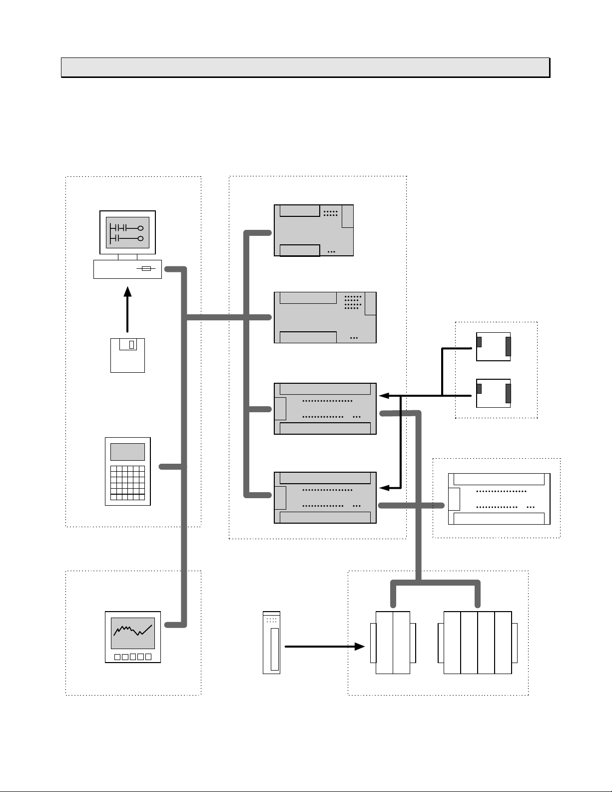
1.3 System configuration
CTi Automation - Phone: 800.894.0412 - Fax: 208.368.0415 - Web: www.ctiautomation.net - Email: info@ctiautomation.net
The following figure shows the T1/ T1S system configuration.
6F3B0250
1. System Configuration
T1 basic unitPeripheral tool
IBM-PC compatible
personal computer
T-PDS
software
Handy programmer
HP911A
T1-16
T1-28
Option cards
T1-40
Expansion unit
T1-40S
Expansion rackComputer link function
MMI/SCADA
system
T2 I/O modules
4-slot2-slot
Basic Hardware and Function
19
Page 22
1. System Configuration
CTi Automation - Phone: 800.894.0412 - Fax: 208.368.0415 - Web: www.ctiautomation.net - Email: info@ctiautomation.net
1.4 I/O expansion
The I/O points on the T1-16 and T1-28 are not expandable. The T1-40 and T1-40S,
however, provides I/O expandability by using the option cards, expansion rack and
expansion unit.
The T1-40/T1-40S can hold up to two option cards. Also, the T1-40/T1- 40S can be
connected to either one expansion rack (2-slot or 4- slot) or one expansion unit. By
using the expansion rack, most of the T2 Series I/O modules can be used with the
T1-40/T1-40S.
Available option cards
·
DI116: 16 points DC input
DO116: 16 points DC output
DD116: 8 points DC input + 8 points DC output
AD121: 1 channel analog input (0 to 5V or 0 to 20mA)
AD131: 1 channel analog input (-10 to +10V)
DA121: 1 channel analog output (0 to 20mA)
DA131: 1 channel analog output (-10 to +10V)
FR112: TOSLI NE- F10 r emote station
6F3B0250
Available expansion racks
·
BU152: Up to 2 I/O modules can be mounted
BU154: Up to 4 I/O modules can be mounted
Available expansion units
·
T1-EDR32: 16 points DC input + 16 points relay output
T1-EAR32: 16 points AC input + 16 points relay output
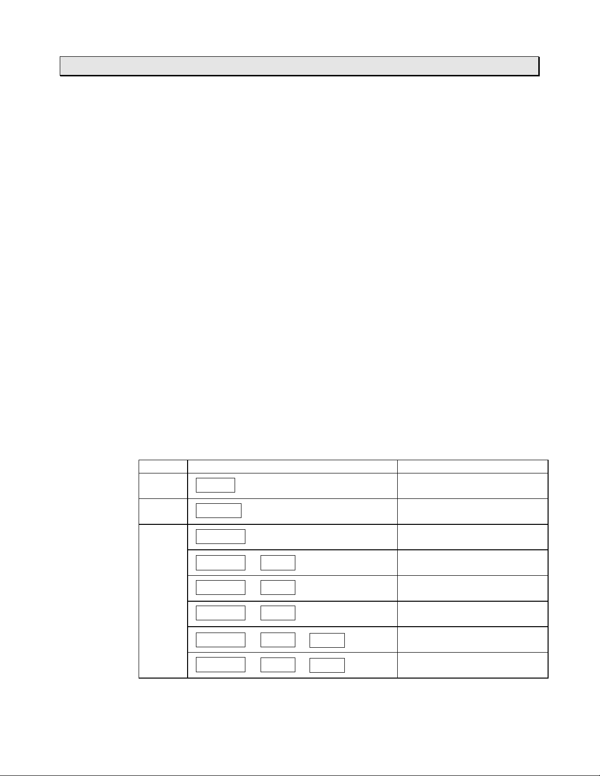
Available I/O expansion configuration
·
Model Unit configuration I/O points
T1-16 16 points (8 in / 8 out)
T1-28 28 points (14 in / 14 out)
T1-40
or
T1-40S 56 points (40 in / 16 out)
T1-16
T1-28
T1-40(S)
T1-40(S)
T1-40(S)
T1-40(S)
T1-40(S)
+
DD116
+
DO116
+
+
DI116
DI116
+
DI116
40 points (24 in / 16 out)
56 points (32 in / 24 out)
56 points (24 in / 32 out)
72 points (56 in / 16 out)
T1-40(S)
T1/T1S User’s Manual
20
+
DI116
+
DD116
72 points (48 in / 24 out)
Page 23
1. System Configuration
CTi Automation - Phone: 800.894.0412 - Fax: 208.368.0415 - Web: www.ctiautomation.net - Email: info@ctiautomation.net
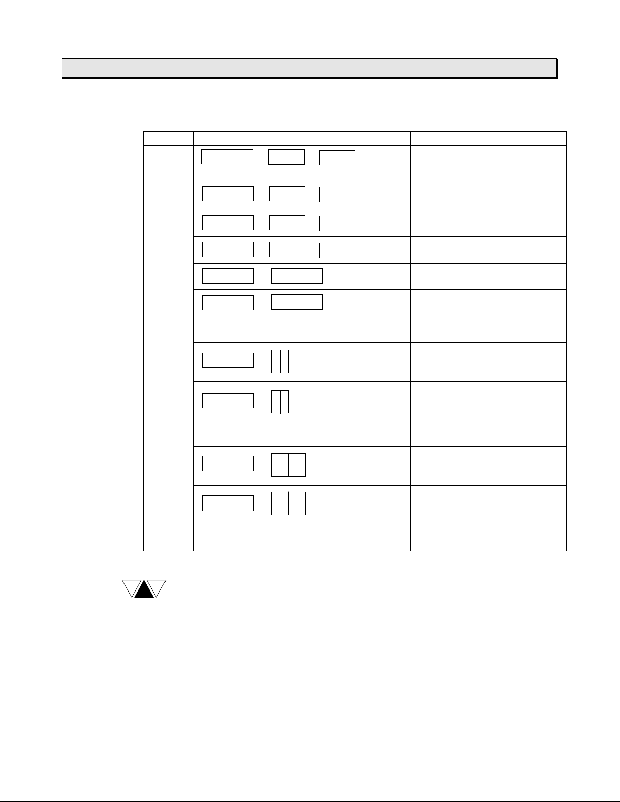
Available I/O expansion configuration (continued)
·
Model Unit configuration I/O points
T1-40
or
T1-40S
T1-40(S)
T1-40(S)
+
+
DI116
or
DD116
DO116
+
DD116
+
72 points (40 in / 32 out)
6F3B0250
T1-40(S)
T1-40(S)
T1-40(S)
T1-40(S)
T1-40(S)
T1-40(S)
T1-40(S)
DD116
+
DO116
+
Exp 32T1-40(S)
+
Exp 32
+
Option cards
+
(any combinations)
+
+
Option cards
+
(any combinations)
+
+
DO116
+
DO116
+
(BU152)
(BU152)
(BU154)
(BU154)
72 points (32 in / 40 out)
72 points (24 in / 48 out)
72 points (40 in / 32 out)
104 points
168 points
200 points
296 points
328 points
Option cards
+
(any combinations)
NOTE
(1) When the TOSLINE-F10 remote station (FR112) is used, only one
additional option card can be inserted into the T1- 40/ T1-40S.
(2) In t he above table, “ Exp 32” m eans t he expansion unit ( T1-EDR32 or
T1-EAR32).
(3) In the above table, I/O points of the combinations with an expansion rack
show the maximum points using 64 points I/O modules.
Basic Hardware and Function
21
Page 24

1. System Configuration
CTi Automation - Phone: 800.894.0412 - Fax: 208.368.0415 - Web: www.ctiautomation.net - Email: info@ctiautomation.net
1.5 Components
1.5.1 Basic unit
The basic unit is available in four models, the T 1- 16, T1-28, T1-40 and T1- 40S.
And each model is available in three types, depending on the power supply and input
types.
Model Type Power supply Input Output
T1-16 T1-MDR16 100- 240 Vac,
T1-MAR16 100-240 Vac,
T1-MDR16D 24 Vdc 8 points - 24 Vdc 6 points - relay,
T1-28 T1-MDR28 100- 240 Vac,
T1-MAR28 100-240 Vac,
T1-MDR28D 24 Vdc 14 points - 24 Vdc 12 points - relay,
T1-40 T1-MDR40 100- 240 Vac,
T1-MAR40 100-240 Vac,
T1-MDR40D 24 Vdc 24 points -24 Vdc 14 points - relay,
T1-40S T1-MDR40S 100-240 Vac,
T1-MAR40S 100-240 Vac,
T1-MDR40SD 24 Vdc 24 points -24 Vdc 14 points - relay,
50/60 Hz
50/60 Hz
50/60 Hz
50/60 Hz
50/60 Hz
50/60 Hz
50/60 Hz
50/60 Hz
6F3B0250
8 points - dry contact
(24 Vdc)
8 points - 120 Vac 6 points - relay,
14 points - 24 Vdc 12 points - relay,
14 points - 120 Vac 12 points - relay,
24 points -24 Vdc 14 points - relay,
24 points - 120 Vac 14 points - relay,
24 points -24 Vdc 14 points - relay,
24 points - 120 Vac 14 points - relay,
6 points - relay,
2 points - transistor
2 points - triac
2 points - transistor
2 points - transistor
2 points - triac
2 points - transistor
2 points - transistor
2 points - triac
2 points - transistor
2 points - transistor
2 points - triac
2 points - transistor
T1/T1S User’s Manual
22
Page 25
¨¨¨¨
CTi Automation - Phone: 800.894.0412 - Fax: 208.368.0415 - Web: www.ctiautomation.net - Email: info@ctiautomation.net
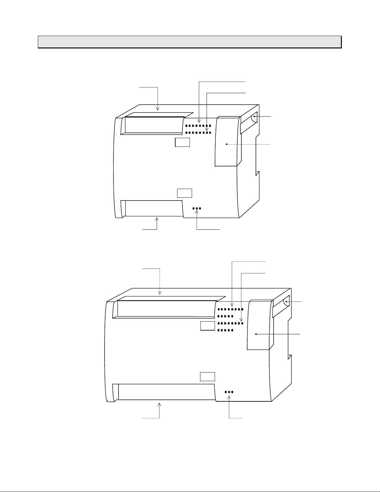
T1-16
6F3B0250
1. System Configuration
Power supply and
Input terminals
Output terminals
T1-28
¨¨¨¨
Power supply and
Input terminals
TOSHIBA
PROSEC
T1
IN
OUT
Input status LEDs
Output status LEDs
Mounting hole
Programmer port cover
MDR16
Operation status LEDs
Input status LEDs
Output status LEDs
TOSHIBA
Output terminals
IN
PROSEC
T1
OUT
MDR28
Operation status LEDs
Basic Hardware and Function
Mounting
hole
Programmer
port cover
23
Page 26
1. System Configuration
CTi Automation - Phone: 800.894.0412 - Fax: 208.368.0415 - Web: www.ctiautomation.net - Email: info@ctiautomation.net
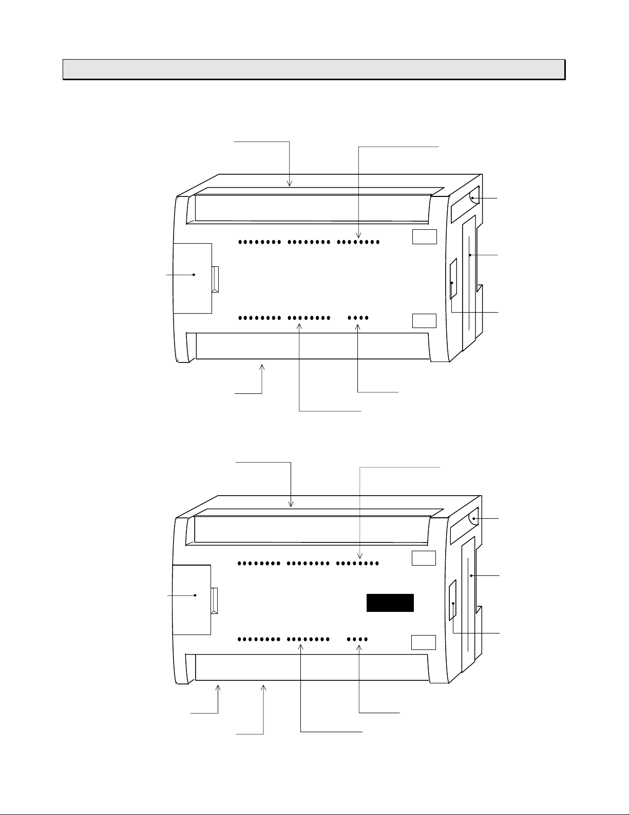
T1-40
¨¨¨¨
6F3B0250
Power supply and
Programmer
port cover
Output terminals
T1-40S
¨¨¨¨
Input terminals
TOSHIBA
PROSEC
T1
Input status LEDs
IN
MDR40
OUT
Operation status LEDs
Output status LEDs
Mounting
hole
Option card
slot
Expansion
connector
Power supply and
Programmer
port cover
Output terminals
Input terminals
TOSHIBA
PROSEC
T1
IN
MDR40S
OUT
Operation status LEDsRS-485 port (terminals)
Output status LEDs
Input status LEDs
Mounting
hole
Option card
slot
Expansion
connector
T1/T1S User’s Manual
24
Page 27
Behind the programmer port cover
CTi Automation - Phone: 800.894.0412 - Fax: 208.368.0415 - Web: www.ctiautomation.net - Email: info@ctiautomation.net
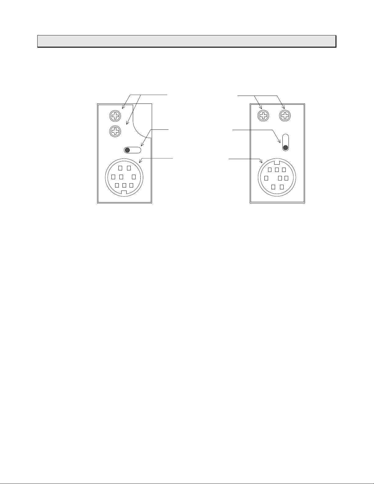
¨¨¨¨
Analog setting adjusters
6F3B0250
1. System Configuration
(V0 and V1)
V
0
V
1
PRG
V
0
Mode control switch
(HALT / RUN)
H / R
Programmer port
connector
V
1
R
/
H
PRG
T1-16 / T1-28 T1-40 / T1-40S
Power supply terminals:
Connect the power cable and grounding wire. The terminal scr ew size is M3.5.
See sections 4.4 and 4.5 for wiring.
Input terminals:
Connect input signal wires. The terminal screw size is M3.5. See section 2.4 for details.
Output terminals:
Connect output signal wires. The terminal scr ew size is M3.5. See section 2.4 f or
details.
Input status LEDs:
Indicate the ON status of each input signal. (color: red)
Output status LEDs:
Indicate the ON status of each out put signal. (color: red)
Basic Hardware and Function
25
Page 28
CTi Automation - Phone: 800.894.0412 - Fax: 208.368.0415 - Web: www.ctiautomation.net - Email: info@ctiautomation.net
1. System Configuration
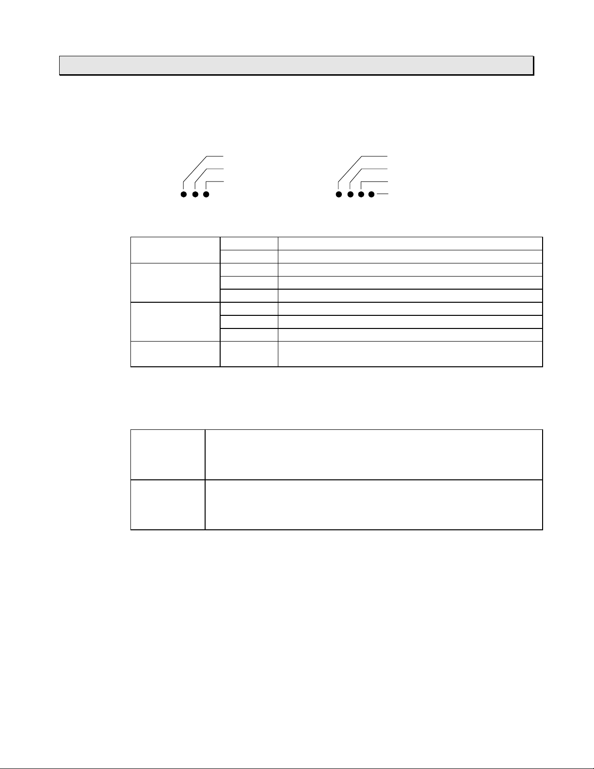
Operation status LEDs:
Indicate the operation status of the T1/T1S.
T1-16 / T1-28 T1-40 / T1-40S
PWR Lit Int er nal 5 Vdc power is norm a l.
(Power) (g r een) Not lit Internal 5 Vdc power is not nor m al.
RUN (green) Blinking HOLD mode
FLT Lit ERRO R mode
(Fault) ( r ed) Blinking Har dware error (programmer cannot be connect ed)
AUX
(Auxiliary) (red)
PWR PWR
RUN RUN
FLT FLT
AUX
Lit RUN mode (in oper at ion)
Not lit HALT mode or ERRO R mode
Not lit Normal
-
Can be controlled by user program. Lit when S320 is
ON and unlit when S320 is OFF. (T1-40/T1-40S)
6F3B0250
Mode control switch:
Controls the operation modes of t he T1/T1S.
H (HALT) When the switch is turned to H (HALT) side, the T1/T1S stops
program execution (HALT mode) . In this position, RUN/HALT
command from the prog rammer is disabled. In case of the T1,
programming is available only in the HALT m ode.
R (RUN) When the switch is turned to R (RUN) side, the T1/T1S starts program
execution. This is the position during normal oper ation.
In this position, RUN/HALT com m and from the progra m m er is also
available.
Analog setting adjusters:
Two analog setting adjusters are provided. The V0 value is stored in SW30 and the V1
value is stored in SW31. The converted value range is 0 to 1000. Refer t o sect ion 8.5
for details of the analog setting function.
Programmer port connector:
Used to connect the programmer cable. The interface is RS-232C. T his por t can also
be used for the computer link funct ion. Ref er to section 1.6 for more inform at ion about
the computer link funct ion.
T1/T1S User’s Manual
26
Page 29

6F3B0250
CTi Automation - Phone: 800.894.0412 - Fax: 208.368.0415 - Web: www.ctiautomation.net - Email: info@ctiautomation.net
1. System Configuration
Option card slot (T1-40/T1-40S):
Used to insert the option cards. Two slots are pr ovided. Refer to separate “T1/ T1S
Use’s Manual - Expansion I/O -” for details of the option cards.
Expansion connector (T1-40/T1-40S):
Used to connect the expansion rack or expansion unit. Refer to separate “T1/T1S Use’s
Manual - Expansion I/O -” for details of the T2 type I/O modules.
RS-485 port (T1-40S only):
Used to connect a computer (SCADA system), operator interface unit, ot her T1S, or
many kinds of serial ASCII devices including Toshiba’s I nverter through RS-485
interface. Refer to section 1.7 for more information about the T1S’s RS-485 m ult ipurpose communication functions.
Mounting holes:
Used to fix the T1/T1S on a mount ing frame by screws. The mounting holes ar e
provided at two opposite corners.
Use two M4 screws for mounting. See section 4.2 for
T1
DIN rail bracket:
The DIN rail bracket is pr ovided at the rear for mounting the T1/T1S on a 35 mm DIN
rail. See section 4.2 for inst alling the unit.
installing the unit.
Basic Hardware and Function
27
Page 30
1. System Configuration
CTi Automation - Phone: 800.894.0412 - Fax: 208.368.0415 - Web: www.ctiautomation.net - Email: info@ctiautomation.net
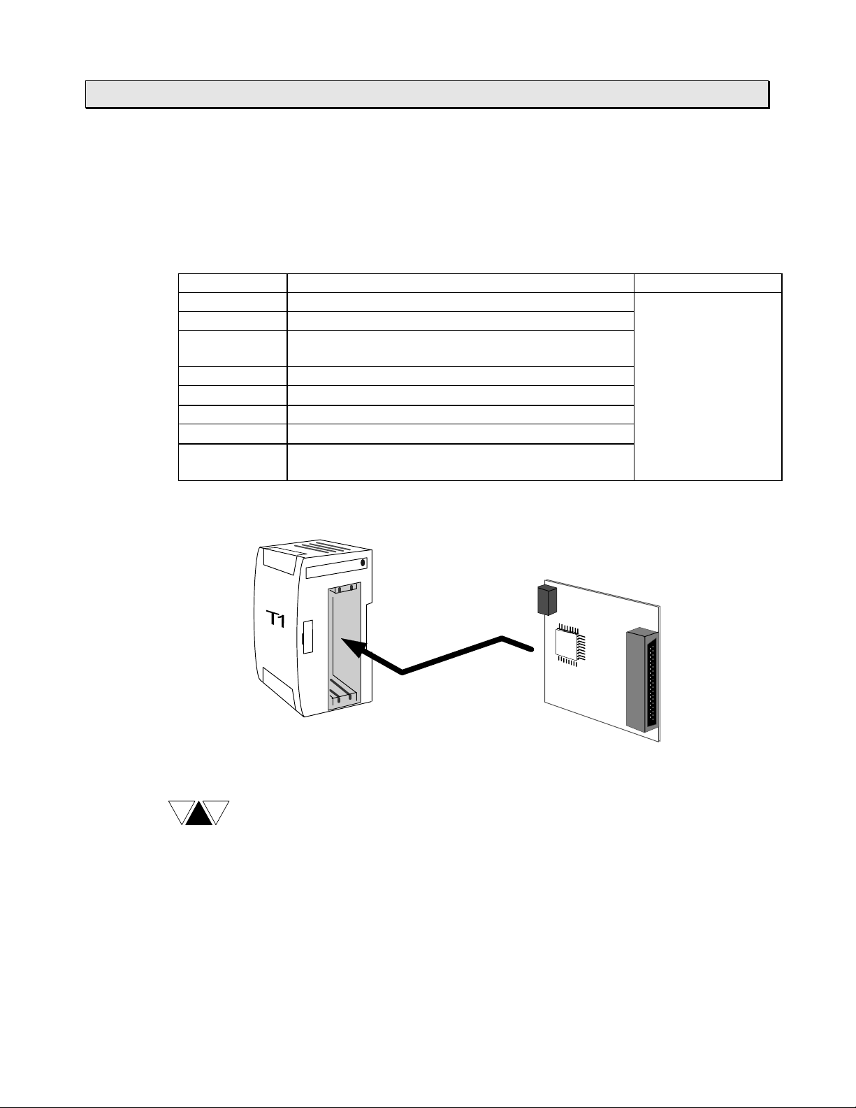
1.5.2 Option cards
The T1-40/T1-40S can hold up to two option cards for expanding I/O points, etc.
The following eight types of t he opt ion car ds are available.
For details of the option cards, r efer to the separate manual “T1/T1S User’s Manual
Expansion I/O -“.
Type Description Power supply
DI116 16 points input, 24 Vdc - 5 mA Supplied from the
DO116 16 points output, 24 Vdc - 100 mA basic unit (5 Vdc)
DD116 8 point s input, 24 Vdc - 5 mA
+ 8 points output, 24 Vdc - 100 mA
AD121 1 channel analog input, 0 to 5 V / 0 t o 20 m A
AD131
DA121 1 channel analog output, 0 to 20 m A
DA131
FR112 TOSLINE-F10 remote station,
1 channel analog input, ±10 V
1 channel analog output, ±10 V
1 word input + 1 word output
6F3B0250
-
T1-40
or
T1-40S
NOTE
Option card
The TOSLINE-F10 remote car d ( FR112) can be used with other cards.
However two FR112s cannot be used together.
T1/T1S User’s Manual
28
Page 31
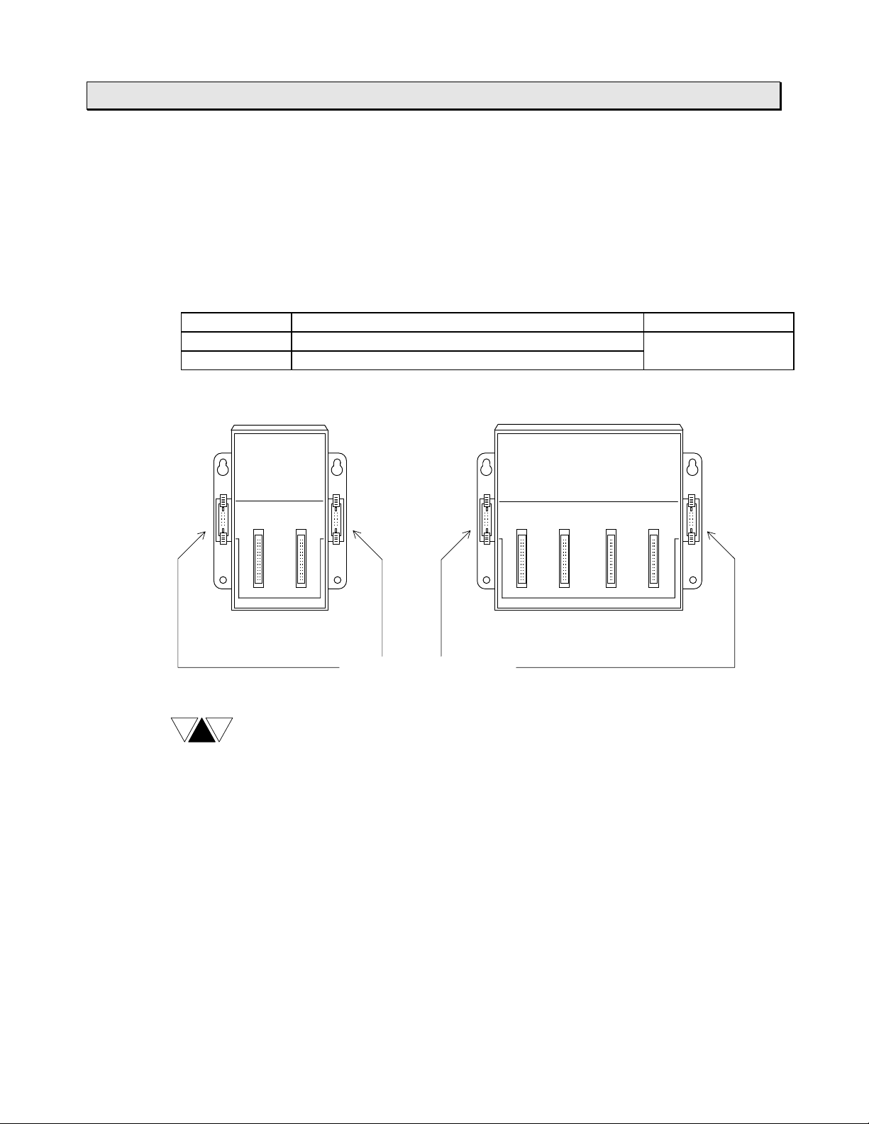
1.5.3 Expansion rack
CTi Automation - Phone: 800.894.0412 - Fax: 208.368.0415 - Web: www.ctiautomation.net - Email: info@ctiautomation.net
The T1-40/T1-40S can be connected to either one expansion rack or one expansion
unit.
The following two types of the expansion racks are available. By using the expansion
rack, T2 Series I/O modules can be used with the T1-40/T1-40S.
For details of the expansion rack, refer to the separate manual “T1/T1S User’s Manual
Expansion I/O -“.
-
Type Description Power supply
BU152 2 slots for I/O modules Supplied from the
BU154 4 slots for I/O modules basic unit
BU152 BU154
6F3B0250
1. System Configuration
NOTE
Expansion connectors
(1) A 0.15 m expansion cable is supplied with the expansion rack.
(2) Internal 5 Vdc power for I/O modules is supplied from the T1-40/T1-40S
basic unit. No power supply module is required on the expansion rack.
(3) Expansion connectors are provided on the both sides. However either one
can be used at a time.
(4) DIN r ail br acket is not provided.
Basic Hardware and Function
29
Page 32

1. System Configuration
CTi Automation - Phone: 800.894.0412 - Fax: 208.368.0415 - Web: www.ctiautomation.net - Email: info@ctiautomation.net
1.5.4 I/O modules
As listed below, various I/O modules are available for the T1-40/T1-40S, allowing it to
be used for a wide variety of applications. Up to four I/O modules can be used with the
T1-40/T1-40S by connecting the expansion rack .
For details of the I/O modules, refer to the separate manual “T1/T1S User’s Manual
Expansion I/O -“.
Type Name Specifications
DI31 DC/AC input 16 points (16 points/common), 12 to 24 Vdc/Vac
DI32 DC input
DI235
IN51 AC input 16 points (16 points/common), 100 to 120 Vac
IN61 16 points (16 points/common), 200 to 240 Vac
RO61 Relay output
RO62 8 points (isolated), 240 Vac/24 Vdc (max.),
DO31 Transistor
output
DO32 (current sink)
DO235
DO233P Transistor
output
(current source)
AC61 Triac out put
AI21 Analog input 4 channels, 1 to 5 V / 4 to 20 mA, 8-bit resolution
AI22 4 channels, 1 to 5 V / 4 to 20 mA, 12-bit resolution
AI31 4 channels, 0 to 10 V, 8-bit resolution
AI32
AO31 Analog output 2 channels, 1 to 5 V / 4 to 20 mA / 0 t o 10 V,
AO22 2 channels, 1 t o 5 V / 4 to 20 mA, 12-bit resolution
AO32
PI21 Pulse input 1 channel (2-phase and zero marker), 5/12 V,
MC11 Positioning
CF211 Communication
interface
6F3B0250
-
32 points (4 ´ 8 points/common), 24 Vdc
64 points (8 ´ 8 points/common), 24 Vdc
12 points (3 ´ 4 points/common),
240 Vac/24 Vdc (max.), 2 A/point, 4 A/com m on (max.)
2 A/point (max.)
16 points (16 points/common), 5 to 24 Vdc,
1 A/point, 1.2 A/4 points (max.)
32 points (4 ´ 8 points/common), 5 to 24 Vdc,
0.1 A/point (max.)
64 points (8 ´ 8 points/common), 5 to 24 Vdc,
0.1 A/point (max.)
16 points (16 points/common), 5 to 24 Vdc,
1 A/point, 1.2 A/4 points (max.)
12 points (3 ´ 4 points/common), 100 to 240 Vac,
0.5 A/point, 0.6 A/SSR (m ax.)
4 channels, ±10 V, 12-bit resolution
8-bit resolution
2 channels, ±10 V, 12-bit resolution
100 kHz (max.), 24-bit counter
1 axis, 200 kHz (max.), 5 to 24 Vdc, ±999999 pulses
1 port of RS-232C, f u ll- duplex, ASCI I code,
300 / 600 / 1200 / 2400 / 4800 / 9600 / 19200 bps
T1/T1S User’s Manual
30
Page 33
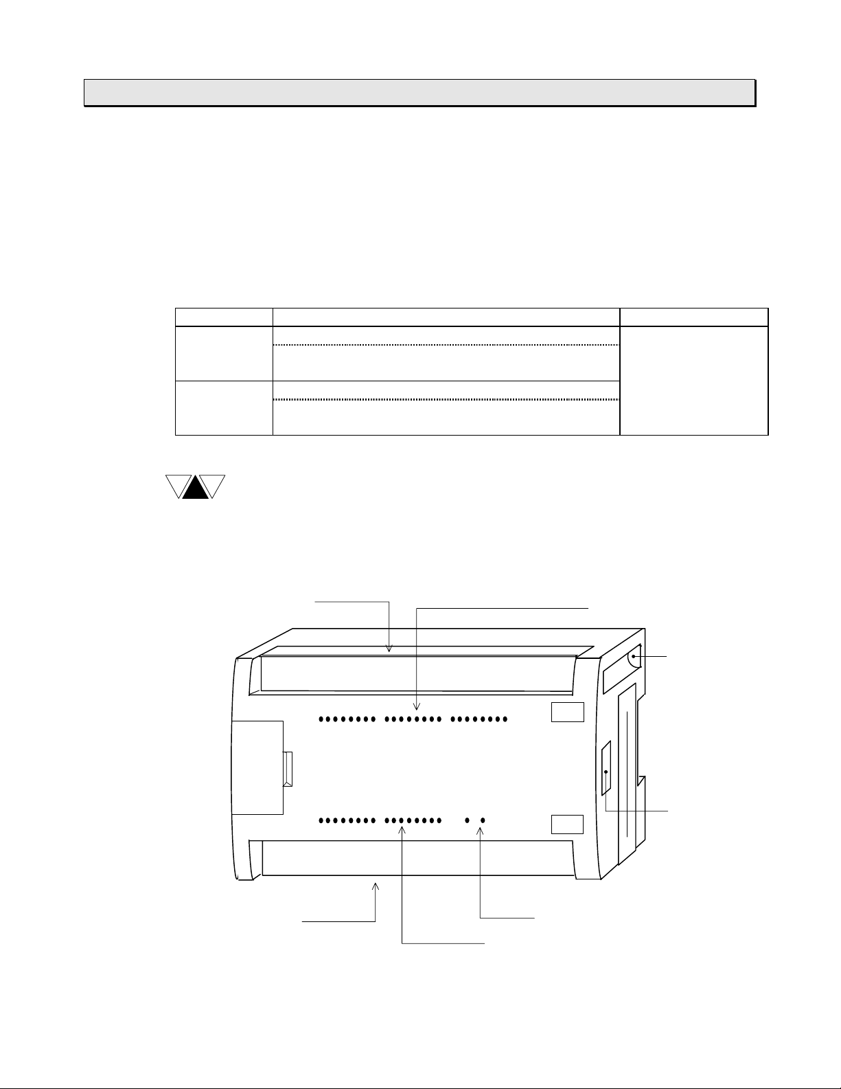
1.5.5 Expansion unit
CTi Automation - Phone: 800.894.0412 - Fax: 208.368.0415 - Web: www.ctiautomation.net - Email: info@ctiautomation.net
The T1-40/T1-40S can be connected to either one expansion rack or one expansion
unit.
The following two types of the expansion units are available. Each expansion unit has
32 points I/O (16 inputs and 16 outputs).
For details of the expansion unit, refer to the separate manual “T1/T1S User’s Manual
Expansion I/O -“.
Type Description Power supply
T1-EDR32 Input: 16 points, 24 Vdc - 7 mA Supplied from the
Output: 16 points, relay, 240 Vac/24 Vdc (max.) -
T1-EAR32 Input : 16 points, 100 to 120 Vac - 7 mA
Output: 16 points, relay, 240 Vac/24 Vdc (max.) -
2 A/point (max.)
2 A/point (max.)
6F3B0250
1. System Configuration
basic unit (5Vdc)
-
NOTE
(1) A 0.5 m expansion cable is supplied with the expansion unit.
(2) Internal 5 Vdc power for expansion unit is supplied from the T1-40/T1-40S
(3) 24 Vdc power for output relay coils is required externally.
(4) DIN r ail br acket is provided.
Power supply and
Input terminals
basic unit.
TOSHIBA
PROSEC
T1
EDR40
Input status LEDs
IN
OUT
Mounting
hole
Expansion
connector
Output terminals
Output status LEDs
Power LEDs (5V and 24V)
Basic Hardware and Function
31
Page 34

1. System Configuration
CTi Automation - Phone: 800.894.0412 - Fax: 208.368.0415 - Web: www.ctiautomation.net - Email: info@ctiautomation.net
1.5.6 Options
The following optional items are available.
Item Type Description
Programmer port
connector
Option card PT15S Cable side connector for DI116, Soldering type
I/O connector PT15F DO116, or DD116 Flat cable type
Expansion cable CS1R2 For connecting the expansion rack , 0. 15 m length,
Empty slot cover
6F3B0250
PT16S For RS-232C computer link, with 2 m cable
(spare parts)
CS1R5B For connecting the expansion unit, 0.5m length,
(spare parts)
-
For covering empty slot on the expansion rack
T1/T1S User’s Manual
32
Page 35
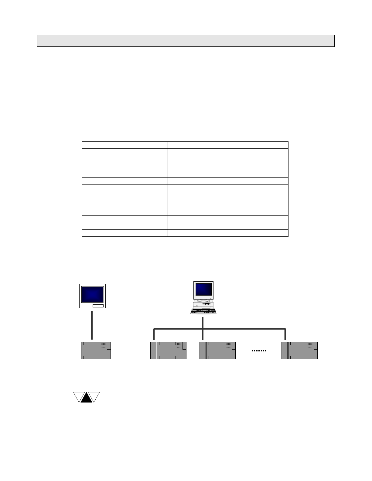
1.6 Computer link system
g
CTi Automation - Phone: 800.894.0412 - Fax: 208.368.0415 - Web: www.ctiautomation.net - Email: info@ctiautomation.net
The interface of t he T1/T1S’s programm er por t is RS-232C. Normally this port is used
to connect the programmer . However, this por t can also be used for the computer link
function.
The computer link is a data comm unicat ion function between computer or operator
interface unit and the T1/ T1S. The data in the T1/T1S can be read and written by
creating simple communication prog r am on the computer. The computer link protocol
of the T1/T1S is published in “ T1/T1S User’s Manual - Communication Function -”.
Item Specifications
Interface Conforms to RS-232C
Transmission system Half-duplex
Synchronization Star t - stop system (asynchronous)
Transmission speed 9600 bps (fixed)
Transmission distance 15 m max.
Framin
Protocol T-series computer link (ASCII)
Transmission delay option 0 t o 300 m s
Start bit:
Data bits:
Parity:
Stop bit:
1 bit
8 bits (fixed)
Odd or none
1 bit (fixed)
Programmer (binary)
6F3B0250
1. System Configuration
By using the multi-drop adapter (CU111), multiple T1/T1Ss can be connected on an
RS-485 line. The T-series PLC programming software (T-PDS) can also be used in this
configuration.
Operator Interface
RS-232C RS-485 (1 km max.)
T1 T1
NOTE
In case of the T1, ther e ar e functional limitations as follows.
·
·
C
U
Multi-drop configuration is available with version 1.10 or lat e r .
Programmer connection in t he m u lt i-drop configuration, none parity and
Master Com puter
C
U
T1
C
U
Max. 32 T1s
T1
transmission delay options are available with version 1.20 or later.
Basic Hardware and Function
33
Page 36
1. System Configuration
y
y
g
y
CTi Automation - Phone: 800.894.0412 - Fax: 208.368.0415 - Web: www.ctiautomation.net - Email: info@ctiautomation.net
1.7 T1S communication function
The T1S has an RS-485 muiti-purpose comm unication port. This port can work
independent of the programmer port.
By using this communication port, one of t he following three communication modes is
available, computer link mode, data link m ode and free ASCII mode.
For details of these funct ions, refer to the separate manual “T1/T1S User’s Manual
Communication Function -”.
Item Computer link Free ASCII Data link
Interface Conforms to RS-458 (4-wire or 2-wire)
Transmission system Half-duplex
Synchronization Start-stop system (asynchronous)
Transmission code ASCII/binar
Transmission speed 300, 600, 1200, 2400, 4800, 9600, or
Transmission distance 1 km max.
Framin
Protocol T-series
Link configuration 1-to-N N/A 1-to-1
Transmission dela
option
ASCII Binar
19200 bps (fixed)
19200 bps
Start bit: 1 bit
Data bits: 7 or 8 bits
Parity: Odd, even, or none
Stop bit: 1 or 2 bits
User defined
computer link
(ASCII),
Programmer
(binary)
0 to 300 ms N/A N/A
ASCII messages
Special
Special
6F3B0250
-
Computer link mode
T-series computer link prot ocol can be used in this mode. A maximum of 32 T1Ss can
be connected to a master computer.
By using this mode, all the T1S’s data can be accessed by a master com put er.
The T-series PLC programming software (T-PDS) can also be used in t his
configuration.
T1/T1S User’s Manual
34
Master Com puter
RS-485 (1 km max.)
T1 T1 T1T1
Max. 32 T1Ss
Page 37

6F3B0250
CTi Automation - Phone: 800.894.0412 - Fax: 208.368.0415 - Web: www.ctiautomation.net - Email: info@ctiautomation.net
1. System Configuration
Data link mode
Two PLCs (any combination of T1S, T 2 E or T2N) can be directly linked together. This
direct link is inexpensive, easily configured and requires no special programming. Data
registers D0000 to D0031 are used for the data transfer.
T1S
T1 T1
RS-485 (1 km max.)
Station No. 1
D0000
D0015
D0016
D0031
T1S
Station No. 2
D0000
D0015
D0016
D0031
Free ASCII mode
User defined ASCII messages can be t r ansmitted and received through this port.
A terminal, printer, bar- code reader, or other serial ASCII device can be directly
connected. This mode also allows the T1S to communicat e with other PLCs ( T1, T2E,
T2N, etc.), Toshiba’s I nvert ers (such as VF-S7/A5, G3), Toshiba’s motor protection
relay (S2E21), or others.
T1S
T1
Bar-code re ader,
Printer, etc.
RS-485 (1 km max.)
T1
T1
Inverter VF-S7
Motor Protection Relay
S2E21
Basic Hardware and Function
35
Page 38

1. System Configuration
(S)
)
)
CTi Automation - Phone: 800.894.0412 - Fax: 208.368.0415 - Web: www.ctiautomation.net - Email: info@ctiautomation.net
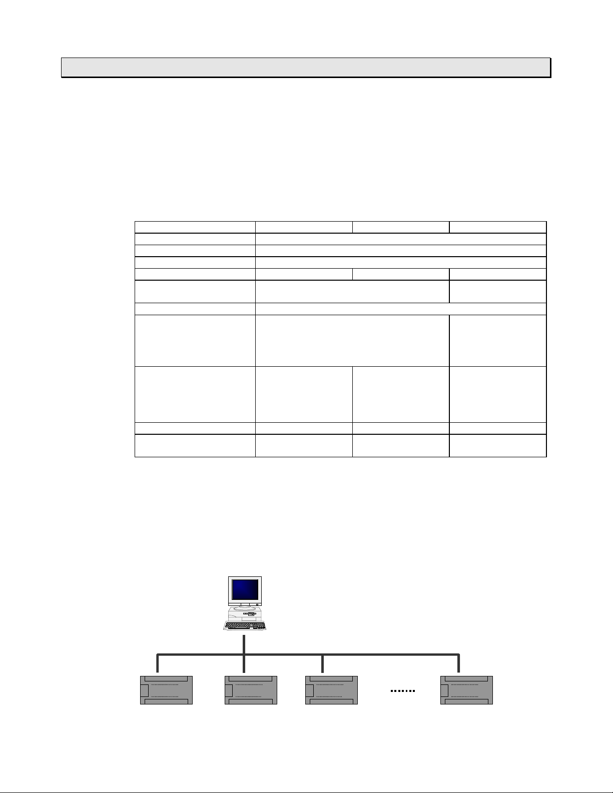
1.8 Real-time data link system TOSLINE-F10
TOSLINE-F10 is a high speed data transm ission system suit ed for small points I/O
distribution system. By inserting the T O SLI NE- F10 r em ote card (FR112) into the T140/T1-40S, the T1-40/ T1-40S can work as a remote station of the TOSLINE-F10
network. On this network, the T1-40/T1-40S sends 1 word data to the mast er station
and receives 1 word data from the master stat ion.
Item TOSLINE-F10 system specifications
Topology Bus (terminated at both ends)
Transmission distance
(without repeater)
Transmission speed 750 kbps 250 kbps
Scan transmission
capacity
Scan cycle 7 ms / 32 words 12 ms/32 words
Error checking CRC check
6F3B0250
High speed mode Long distance mode
500 m max. (total) 1 km max. (tot al)
512 points (32 words) max.
NOTE
(1) Ref er to the separate “T1 User’s Manual - Option Card and I/O
Module -“ for details of the TOSLINE-F10 remote card (FR112) .
(2) Ref er to the separate TOSLINE-F10 User’s Manual for details of overall
TOSLINE-F10 system.
Typical data link configuration
The figure below shows the typical data link configuration.
Master
computer
T2E
(master)
TOSLINE-F10
T1-40(S
T1-40(S
T2E
(remote)
RI/ORI/OT1-40
RI/O: remote I/O
Operator interface units
T1/T1S User’s Manual
36
Page 39

1.9 Peripheral tools
CTi Automation - Phone: 800.894.0412 - Fax: 208.368.0415 - Web: www.ctiautomation.net - Email: info@ctiautomation.net
The following peripheral tools are available for the T1/T1S.
T-Series Program Development System (T-PDS)
The T-Series Program Development System ( T-PDS) is a software which runs on any
IBM-PC compatible personal computers such as Toshiba’s Notebook com puters. The
same T-PDS software supports on-line/off-line prog r am m ing, debugging and program
documentation for all the T-Series programmable controllers T1/T1S, T2/T2E/T2N and
T3/T3H.
User-friendly program editor includes cut & paste, address search & replace,
·
program block move/copy, etc.
Group programming - part program development by multiple desig ner s and
·
merging them into a complete program - enhance the software productivity.
Powerful monitoring, I/O force and data set functions fully support your program
·
debugging.
Documentation of programs with commentary makes your maintenance work easy.
·
Remote monitoring/prog r amming via modem (radio/phone) is possible.
·
6F3B0250
1. System Configuration
The table below shows the T-PDS versions that support the T1/ T1S.
Type Part number Versions available for
T1 T1S
T-PDS for Windows TMW33E1SS Ver 1.0 or later
T-PDS for MS-DOS TMM33I1SS Ver 1.61 or later
*1)
*1)
Ver 1.2 or later
Ver 2.1 or later
*1) The T1S can be used with these versions. However, in this case, t her e are the
following functional limitat ions.
The program size setting is only available as 2 k. It is set to 4 k mode in the T1S.
·
Some of the added instructions (MAVE, DFL, HT OA, ATOH) may not be
·
edited/monitored. (depending on t he version)
NOTE
The connection cable for the T1 Series is different from that for upper T-Series
PLCs. These cables are supplied separately.
Connection cable for T1/T1S . . . Type: CJ105, 5 m length
Connection cable for T2/T3 ¼. Type: CJ905, 5 m length
Basic Hardware and Function
37
Page 40

1. System Configuration
CTi Automation - Phone: 800.894.0412 - Fax: 208.368.0415 - Web: www.ctiautomation.net - Email: info@ctiautomation.net
T-Series Handy Programmer (HP911A)
The HP911A is a hand-held programmer, that can be used to program the T1/T1S
using ladder diagram. I t s por t abilit y makes it ideal for maint enance use at r e m ot e
locations.
The HP911A has the following features.
The HP911A supports ladder diagram pr ogramming of T- Series programmable
·
controllers T1/T1S, T2/T2E/T2N and T3.
Built-in EEPROM allows program copy between T-Series controller s .
·
Two display modes are available,
·
- Normal: 5 lines and 12 columns
- Zoom: Full device description
On-line data set and I/O force are useful for system checking.
·
Backlit LCD display allows operation in dim light.
·
6F3B0250
There are two types of the Handy Programm er (HP911) depending on the cable
included with.
Type Part number Cable included with Versions available for T1/T1S
HP911A
HP911
The T1S can be used with the HP911(A). However, there are the following functional
limitations.
The program size setting is only available as 2 k. I t is set to 4 k mode in the T1S.
·
Some of the added instructions (MAVE, DFL, HT OA, ATOH) cannot be
·
edited/monitored.
NOTE
THP911A*S
THP911**S
A 2 m connection cable for the T1/T1S (Type: CJ102) is supplied with the
HP911A. The cable for the T2/T3 is available separately. (Type: CJ902, 2 m
length)
2 m cable for T1/T1S Ver 1.1 or later
2 m cable for the upper
T-series PLCs
Ver 1.1 or later
T1/T1S User’s Manual
38
Page 41

Program Storage Module (RM102)
CTi Automation - Phone: 800.894.0412 - Fax: 208.368.0415 - Web: www.ctiautomation.net - Email: info@ctiautomation.net
6F3B0250
1. System Configuration
The program storag e m odule (RM102) is an
external memory for storing the T1/T1S
program. By using the RM102, program saving
from the T1/T 1S to the RM102, and program
loading from the RM102 to the T1/ T1S can be
done without need of a programmer.
Because the RM102 has an EEPROM,
maintenance-free progr am storage and quick
saving/loading are available.
Multi-drop adapter (CU111)
The T1/T1S’s RS-232C programmer port
supports the computer link function.
When two or more T1/T1Ss are connected with
a master computer, the multi-drop adapter
(CU111) can be used. (One-to-N configuration)
The CU111 is an RS-232C/RS-485 converter
specially designed for the T1/T1S’s
programmer port.
Basic Hardware and Function
39
Page 42

6F3B0250
CTi Automation - Phone: 800.894.0412 - Fax: 208.368.0415 - Web: www.ctiautomation.net - Email: info@ctiautomation.net
T1/T1S User’s Manual
40
Page 43

Section 2
CTi Automation - Phone: 800.894.0412 - Fax: 208.368.0415 - Web: www.ctiautomation.net - Email: info@ctiautomation.net
Specifications
6F3B0250
2.1 General specifications, 42
2.2 External dimensions, 43
2.3 Functional specifications, 46
2.4 I/O specifications, 48
Basic Hardware and Function
41
Page 44

2. Specifications
g
g
g
g
g
g
g
g
g
g
g
g
g
g
CTi Automation - Phone: 800.894.0412 - Fax: 208.368.0415 - Web: www.ctiautomation.net - Email: info@ctiautomation.net
2.1 General specifications
Power supply voltage 100 to 240 Vac (+10/-15 %), 50/60 Hz
Power consumption 30 VA or less 38 VA or less 45 VA or less
Inrush current 50 A or less (at 240 Vac, cold start)
24 Vdc output ratin
(24 Vdc, ±10%)
5 Vdc output ratin
Power supply voltage 24 Vdc (+20/-15 %)
Power consumption 12 W or less 18 W or less
Inrush current 25 A or less (at 24 Vdc)
5 Vdc output ratin
Retentive power interruption 10 ms or less
Insulation resistance
Withstand voltage 1500 Vac - 1 minute
Ambient temperature
Ambient humidity 20 to 90% RH, no condensation
Noise immunity
Vibration immunity 16.7 Hz - 3 mm p-p (3 mutually perpendicular axes)
Shock immunity 98 m/s2 (10 g)
Approximate weight 500
6F3B0250
Item T1-16 T1-28 T1-40 T1-40S
0.1 A for
service power
+
power for dry
contact inputs
-
-
10 MW or more
(between power terminals and
(between power terminals and
0 to 55 °C (operation), -20 to 75 °C (stora
1000 V p-p/1 ms, Conform to EMC Directive 89/336/EEC
(3 shocks per axis, on 3 mutually perpendicular axes)
Option card: 50
Expansion unit: 600
0.2 A (for external devices and/or for input
nals)
si
1 A (for option card and/or
expansion rack/unit)
1 A (for option card and/or
expansion rack/unit)
round terminal)
round terminal)
e)
700
800
2-slot expansion rack: 600
4-slot expansion rack: 800
NOTE
(1) 24 Vdc service power output is not provided on the AC input type and DC
power supply type.
(2) 5 Vdc output capacity of T1-40/T1-40S is reduced by 0.2 A with using
HP911A, and by 0.1 A with using RS-485 port.
T1/T1S User’s Manual
42
Page 45

2.2 External dimensions
CTi Automation - Phone: 800.894.0412 - Fax: 208.368.0415 - Web: www.ctiautomation.net - Email: info@ctiautomation.net
T1-16
¨¨¨¨
6F3B0250
2. Specifications
2-Æ5
¨¨¨¨
T1-28
2-Æ5
[mm]
Basic Hardware and Function
43
Page 46

2. Specifications
CTi Automation - Phone: 800.894.0412 - Fax: 208.368.0415 - Web: www.ctiautomation.net - Email: info@ctiautomation.net
T1-40/T1-40S, Expansion unit
¨¨¨¨
6F3B0250
2-Æ5
Option card
¨¨¨¨
43.18
A
Additional space for Option card connector
Card type A
DI116, DO116, DD116 55
AD121, AD131, DA121, DA131 16
FR112 11
[mm]
T1/T1S User’s Manual
44
Page 47

4-Æ5
CTi Automation - Phone: 800.894.0412 - Fax: 208.368.0415 - Web: www.ctiautomation.net - Email: info@ctiautomation.net
2-slot expansion rack
¨¨¨¨
69.0
83.0
97.0
6F3B0250
2. Specifications
106.5
115.0
143.0 (terminal block)
168.0 (connector)
4-Æ5
4-slot expansion rack
¨¨¨¨
135.0
149.0
163.0
[mm]
Basic Hardware and Function
45
Page 48

2. Specifications
g
g
g
g
g
CTi Automation - Phone: 800.894.0412 - Fax: 208.368.0415 - Web: www.ctiautomation.net - Email: info@ctiautomation.net
2.3 Functional specifications
Item T1-16 T1-28 T1-40 T1-40S
Control method Stored program, cyclic scan system
Scan system Floating scan or constant scan (10 - 200 ms, 10 ms units)
I/O update Batch I/O refresh (direct I/O instruction available)
Program memory RAM (capacitor back-up) and EEPROM (no back-up battery required)
RAM memory backup
Program capacity 2 k steps 8 k steps
Programmin
language
Instructions Basic ladder instructions: 17
Execution speed
Program types 1 main program
User I/O register 512 points/32 words (X/XW, Y/YW)
data Auxiliary
relay
Special
relay
Timer 64 points (T./T), 32 @ 0.01 s, 32 @ 0.1 s 256 points (T./T)
Counter 64 points (C./C) 256 points (C./C)
Data
ister
re
Index
ister
re
I/O capacity 16 points
Input
type
Output
type
I/O terminal block Fixed Removable
DC input
(Note)
type
AC input
type
DC input
type
AC input
type
6F3B0250
6 hours (25°C) 168 hours (25°C)
(4 k or 8 k mode)
Ladder dia
Function block instructions: 76
1.4 ms/contact, 2.3 ms/coil,
4.2 ms/16-bit transfer, 6.5 ms/16-bit addition
1 sub-program (initial program)
1 timer interrupt (interval: 5 to 1000 ms, 5 ms units)
4 I/O interrupt (high-speed counter and interrupt input)
16 subroutines (nesting not available) 256 subroutines
1024 points/64 words (R/RW) 4096 points/
1024 points/64 words (S/SW)
1024 words (D) 4096 words (D)
3 words (I, J, K)
(fixed)
Dry contact input
(AC PS),
24 Vdc input
(DC PS)
100 - 120 Vac input
Relay + transistor (2 points)
Relay + triac (2 points)
ram with function block
28 points
(fixed)
24 Vdc input
Basic: 21
Function: 99
(up to 3 levels of
nestin
256 words
(R/RW)
64 @ 0.01 s,
192 @ 0.1 s
40 points (basic)
+ 32 points (option cards)
+ 16 words (I/O modules)
)
T1/T1S User’s Manual
46
Page 49

Functional specifications (cont’d)
g
g
g
g
g
g
g
g
CTi Automation - Phone: 800.894.0412 - Fax: 208.368.0415 - Web: www.ctiautomation.net - Email: info@ctiautomation.net
Item T1-16 T1-28 T1-40 T1-40S
Real-time clock
/calendar
Special I/O functions
(Note)
Communications
interface
Debug support
function
No Yes,
High speed counter (2 single or 1 quadrature),
Interrupt input (2 points),
Adjustable analo
Pulse output (CW+CCW or pulse+direction),
PWM output
1 port RS-232C (programmer port)
- for Pro
-
-
Sampling trace
(8 devices - 256 times or 1 re
-
-
rammer or Computer link connection
register (2 points),
ister - 128 times)
2. Specifications
(±30 s/month)
1 port RS-485
- Pro
- Computer link
- Data link
- Free ASCII
TOSLINE-F10 remote
(by option card)
Samplin
(8 devices and
3 re
times)
On-line
pro
On-line
EEPROM write
6F3B0250
rammer
trace
ister - 256
rammin
NOTE
(1) T he input specification of the T1- 16 ( AC power type) is dry contact input,
which supplies the power for input signals (24 Vdc) fr om the unit.
Other types are DC input, which requires external power for input signals.
(2) Hig h speed count er, interrupt input, pulse output and PWM output are
available in the DC input types.
(3) Hig h speed count er and interrupt input cannot be used simultaneously.
(4) Pulse output and PWM output cannot be used simultaneously.
Basic Hardware and Function
47
Page 50

2. Specifications
*1
*2
g
g
g
g
*3
*4
*3
*4
*1, *2
CTi Automation - Phone: 800.894.0412 - Fax: 208.368.0415 - Web: www.ctiautomation.net - Email: info@ctiautomation.net
2.4 I/O specifications
2.4.1 T1-16
T1-16 input specifications
····
Item Specifications
Input type Dry contact input,
Number of input
points
Rated input voltage Supplied from
Rated input current 7 mA (at 24 Vdc) 7 mA (at 100 Vac)
ON level Contact close
OFF level Contact open
ON delay time 0 to 15 ms
OFF delay time 0 to 15 ms
Input signal display LED display for all points, lit at ON, internal logic side
External connection Terminal block (fixed), M3.5
Withstand voltage 1500 Vac, 1 minute (between internal and external circuits)
Internal circuit
DC input type AC input type
AC power type DC power type
current source or
sink
DC input,
current source or
sink
AC input
8 points (8 points/common) 8 points (8 points/common)
T1-16
24 Vdc,
+10/-15%
100 - 120 Vac, +10/-15 %,
50/60 Hz
(24 Vdc, ±10 %)
(max. 1.2 kW)
(min. 20 kW)
Min. ON
volta
e: 15 Vdc
Min. OFF
volta
e: 5 Vdc
Min. ON volta
Max. OFF volta
e: 80 Vac
e: 30 Vac
25 ms or less + user setting
30 ms or less + user setting
LED
0
0
6F3B0250
LED
7
13
-
+
7
C
24 Vdc
(AC power type only)
*1: The input current direction (source or sink) of the dry contact input can be selected by the
internal jumper plug. (Factory setting = current source) Refer to section 3.1.
3 side: current flows from input terminal to (-) terminal (current source)
1 side: current flows from (+) terminal to input terminal (current sink)
*2: The jumper plug of the DC power supply type must be set to 1 side.
*3: The input ON/OFF delay time of the DC input type can be changed by user. The setting range is
0 to 15 ms. (Default value = 10 ms) Refer to section 8.2.
*4: The input ON/OFF delay time of the AC input can be extended by user. The extension setting
range is 0 to 15 ms. (Default value = 10 ms) Resulting the default delay times are 35 ms (ON
delay) and 40 ms (OFF delay). Refer to section 8.2.
T1/T1S User’s Manual
48
Page 51

Input signal connections
CTi Automation - Phone: 800.894.0412 - Fax: 208.368.0415 - Web: www.ctiautomation.net - Email: info@ctiautomation.net
····
< DC input (AC power) type >
Current source Current sink
6F3B0250
2. Specifications
Current flow
Current
flow
6420L
N
N
-
7531
IN
-
T1-16
Vin
Vin
+
C0
Note) The factory setting is current source.
27252321
26242220
OUT
C1
+
C0
< DC input (DC power) type > < AC input type >
24 Vdc input
100 - 120 Vac input
6420L
T1-16
27252321
26242220
7531
C1
IN
OUT
24Vdc
6420+
7531C-
IN
T1-16
NCNC
C0
Note) 24 Vdc service power output is not provided
on the DC power supply type.
27252321
26242220
OUT
C1
100 - 120 Vac
T1-16
NC
C0
C0
Basic Hardware and Function
6420L
7531CN
IN
27252321
26242220
OUT
C1
49
Page 52
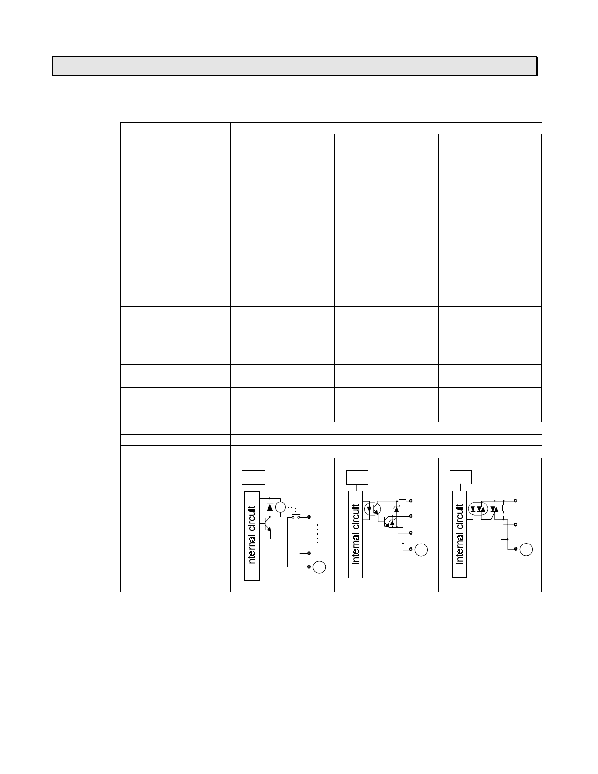
2. Specifications
0
0
CTi Automation - Phone: 800.894.0412 - Fax: 208.368.0415 - Web: www.ctiautomation.net - Email: info@ctiautomation.net
T1-16 output specifications
····
Output type Relay contact,
Number of output points 6 points
Rated load voltage 240 Vac/24 Vdc (max.) 24 Vdc 100 - 240 Vac
Range of load voltage Max. 264 Vac/125Vdc 20.0 - 28.0 V 24 - 264 Vac
Maximum load current 2 A/point (resistive),
ON resistance
Voltage drop at ON
Leakage current at OFF None 0.1 mA or less 1 mA or less
Minimum load 5 Vdc, 10 mA
ON delay time 10 ms or less 0.1 ms or less 1 ms or less
OFF delay time 10 ms or less 0.1 ms or less 1 ms + 1/2 cycle or
Input signal display LED display for all points, lit at ON, internal logic side
External connection Terminal block (fixed), M3.5
Withstand voltage 1500 Vac, 1 minute (between internal and external circuits)
Internal circuit
Item Specifications
Relay output
(both DC input and
Transistor output
(DC input type)
AC input types)
Transistor output,
normally open
current sink
2 points
(6 points/common)
(2 points/common)
0.5 A/point
4 A/common
50 mW or less
(resistive)
--
(initial value)
-
1.5 V or less 1.5 V or less
-
(50 mW)
LED
LED
6F3B0250
Triac output
(AC input type)
Triac output
2 points
(2 points/common)
(50/60 Hz)
(47 - 63 Hz)
1.0 A/point
(resistive)
(at 100 Vac, 50 Hz),
2 mA or less
(at 240 Vac, 50 Hz)
100mA (24 Vac),
50mA (100 - 240 Vac)
less
LED
R
22
27
C1
Vin
2
21
C0
2
21
C0
*1: The switching life of the relay output is as follows.
20 million times or more (mechanical)
100 thousand times or more (electrical, at maximum rated voltage and current)
T1/T1S User’s Manual
50
Page 53

Output signal connections
CTi Automation - Phone: 800.894.0412 - Fax: 208.368.0415 - Web: www.ctiautomation.net - Email: info@ctiautomation.net
····
6F3B0250
2. Specifications
< DC input type
N
+
C0
24 Vdc 240 Vac/24 Vdc (max.)
Transistor
outputs
6 relays and 2 transistors >
----
6420L
7531
-
IN
T1-16
Vin
27252321
26242220
OUT
C1
PS
Relay outputs
Note) 24 Vdc service power output is
not provided on the DC power
supply type.
< AC input type
6 relays and 2 triacs >
----
6420L
7531CN
IN
T1-16
C0NC
C0
27252321
26242220
100 - 240 Vac 240 Vac/24 Vdc (max.)
Triac
OUT
C1
PS
Relay outputs
outputs
Basic Hardware and Function
51
Page 54

2. Specifications
g
g
CTi Automation - Phone: 800.894.0412 - Fax: 208.368.0415 - Web: www.ctiautomation.net - Email: info@ctiautomation.net
2.4.2 T1-28
T1-28 input specifications
····
Input type DC input,
Number of input points 14 points (14 points/common) 14 points (14 points/common)
Rated input voltage 24 Vdc, +10/-15 % 100 - 120 Vac, +10/-15 %,
Rated input current 7 mA (at 24 Vdc) 7 mA (at 100 Vac)
Min. ON voltage 15 Vdc 80 Vac
Max. OFF voltage 5 Vdc 30 Vac
ON delay time 0 to 15 ms (X00 - X07)
OFF delay time 0 to 15 ms (X00 - X07)
Input signal display LED display for all points, lit at ON, internal logic side
External connection Removable terminal block, M3.5
Withstand voltage 1500 Vac, 1 minute (between internal and external circuits)
Internal circuit
Item Specifications
DC input type AC input type
AC input
current source/sink
50/60 Hz
*1
10 ms or less (X08 - X0D)
*1
10 ms (X08 - X0D)
LED
25 ms or less + user settin
(X00 - X07)
25 ms or less (X08 - X0D)
30 ms or less + user settin
(X00 - X07)
30 ms or less (X08 - X0D)
6F3B0250
*2
*2
LED
0
D
C
*1: The input ON/OFF delay time of the leading 8 points of the DC input can be changed by user.
The setting range is 0 to 15 ms. (Default value = 10 ms) Refer to section 8.2.
*2: The input ON/OFF delay time of the leading 8 points of the AC input can be extended by user.
The extension setting range is 0 to 15 ms. (Default value = 10 ms) Resulting the default delay
times of these points are 35 ms (ON delay) and 40 ms (OFF delay). Refer to section 8.2.
0
D
C
T1/T1S User’s Manual
52
Page 55

Input signal connections
CTi Automation - Phone: 800.894.0412 - Fax: 208.368.0415 - Web: www.ctiautomation.net - Email: info@ctiautomation.net
····
< DC input type >
24 Vdc
service power
6F3B0250
2. Specifications
24 Vdc input
24 Vdc
NC
C
-
L
N
31
20+
64 CA8
B975
D
IN
T1-28
Vin
C0
Note) The 24 Vdc service power output is not provided on the DC power supply type.
2220
C1
26242321
C2
2725
C2
2C2A28
C3
2D2B29
OUT
C3
< AC input type >
100 - 120 Vac input
100 - 120 Vac
NC
L
N
C
NCNC
31
20
64 CA8
DB975
IN
T1-28
OUT
C3
53
C0
C0
26242321
C2
2220
C1
2725
C2
2C2A28
C3
2D2B29
Basic Hardware and Function
Page 56

2. Specifications
CTi Automation - Phone: 800.894.0412 - Fax: 208.368.0415 - Web: www.ctiautomation.net - Email: info@ctiautomation.net
T1-28 output specifications
····
Output type Relay contact,
Number of output points 12 points
Rated load voltage 240 Vac/24 Vdc (max.) 24 Vdc 100 - 240 Vac
Range of load voltage Max. 264 Vac/125Vdc 20.0 - 28.0 V 24 - 264 Vac
Maximum load current 2 A/point (resistive),
ON resistance
Voltage drop at ON
Leakage current at OFF None 0.1 mA or less 1 mA or less
Minimum load 5 Vdc, 10 mA
ON delay time 10 ms or less 0.1 ms or less 1 ms or less
OFF delay time 10 ms or less 0.1 ms or less 1 ms + 1/2 cycle or
Output signal display LED display for all points, lit at ON, internal logic side
External connection Removable terminal block, M3.5
Withstand voltage 1500 Vac, 1 minute (between internal and external circuits)
Internal circuit
Item Specifications
Relay output
(both DC input and
Transistor output
(DC input type)
AC input types)
Transistor output,
normally open
current sink
2 points
(1 ´ 2 pts/common,
(2 points/common)
1 ´ 4 pts/common,
1 ´ 6 pts/common)
0.5 A/point (resistive) 1.0 A/point
4 A/common
50 mW or less
--
(initial value)
-
1.5 V or less 1.5V or less
-
(50 mW)
LED
LED
6F3B0250
Triac output
(AC input type)
Triac output
2 points
(2 points/common)
(50/60 Hz)
(47 - 63 Hz)
(resistive)
(at 100 Vac, 50Hz),
2 mA or less
(at 240 Vac, 50Hz)
100 mA (24 Vac),
50 mA (100 - 240 Vac)
less
LED
Ry
22
23
C1
24
27
C2
28
2D
C3
Vin
20
21
C0
20
21
C0
*1: The switching life of the relay output is as follows.
20 million times or more (mechanical)
100 thousand times or more (electrical, at maximum rated voltage and current)
T1/T1S User’s Manual
54
Page 57

CTi Automation - Phone: 800.894.0412 - Fax: 208.368.0415 - Web: www.ctiautomation.net - Email: info@ctiautomation.net
2. Specifications
Output signal connections
····
6F3B0250
< DC input type
L
N
Vin
C0
24 Vdc
Transistor
outputs
12 relays and 2 transistors >
----
NC
C
-
31
20+
64 CA8
T1-28
26242321
C2
2220
C1
PS PS PS PS
2725
C2
2C2A28
2D2B29
DB975
IN
C3
OUT
C3
Relay outputs
240 Vac/24 Vdc (max.)
< AC input type
100 - 240 Vac
Triac
outputs
12 relays and 2 triacs >
----
L
C0
N
C0
NC
NCNC
2220
C1
PS PS PS PS
31C
20
26242321
2725
C2
C2
64 CA8
T1-28
2C2A28
C3
2D2B29
C3
Relay outputs
DB975
IN
OUT
240 Vac/24 Vdc (max.)
Basic Hardware and Function
55
Page 58
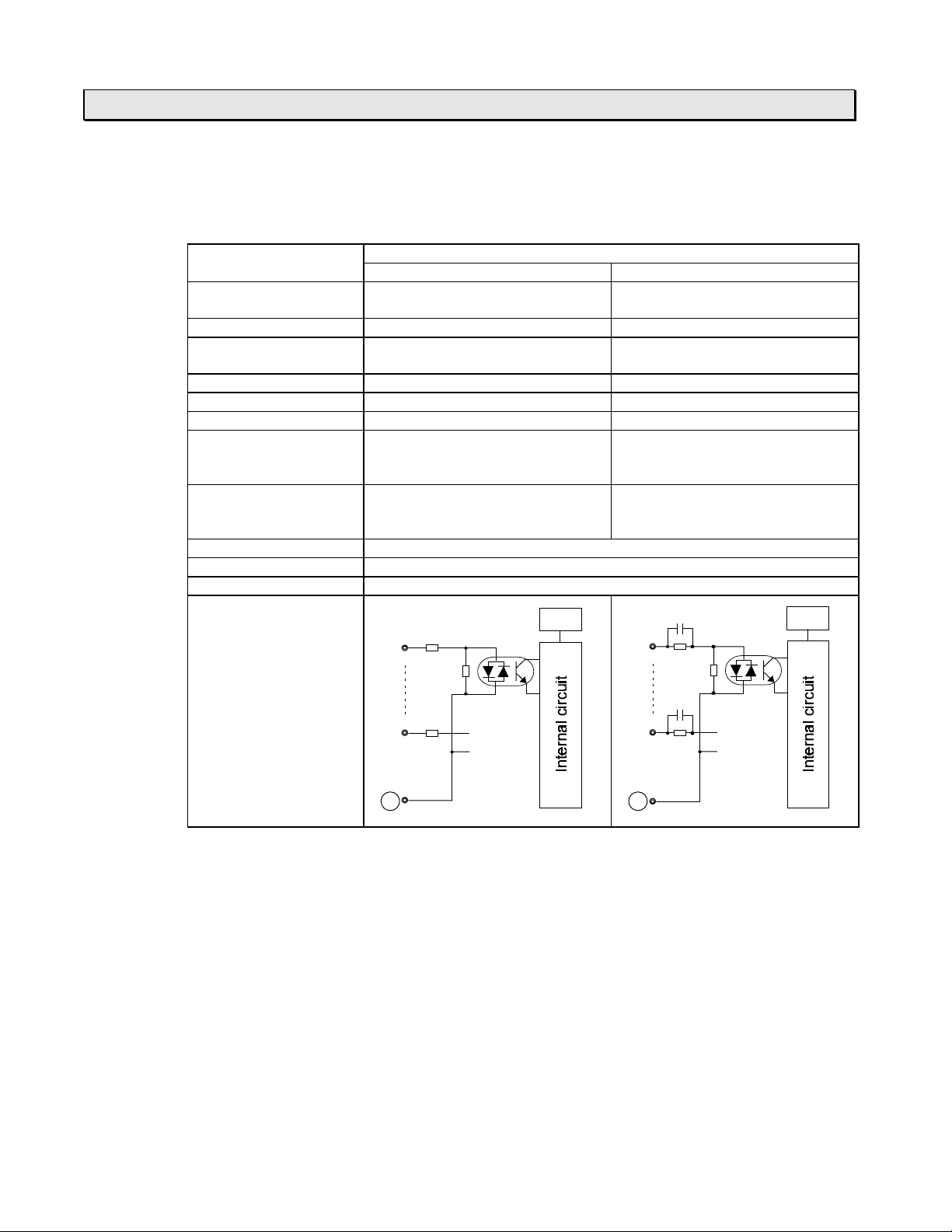
2. Specifications
g
g
CTi Automation - Phone: 800.894.0412 - Fax: 208.368.0415 - Web: www.ctiautomation.net - Email: info@ctiautomation.net
2.4.3 T1-40/T1-40S
T1-40/T1-40S input specifications
····
Input type DC input,
Number of input points 24 points (24 points/common) 24 points (24 points/common)
Rated input voltage 24 Vdc, +10/-15 % 100 - 120 Vac, +10/-15 %,
Rated input current 7 mA (at 24 Vdc) 7 mA (at 100 Vac)
Min. ON voltage 15 Vdc 80 Vac
Max. OFF voltage 5 Vdc 30 Vac
ON delay time 0 to 15 ms (X00 - X07)
OFF delay time 0 to 15 ms (X00 - X07)
Input signal display LED display for all points, lit at ON, internal logic side
External connection Removable terminal block, M3.5
Withstand voltage 1500 Vac, 1 minute (between internal and external circuits)
Internal circuit
Item Specifications
DC input type AC input type
AC input
current source/sink
50/60 Hz
*1
10 ms (X08 - X17)
*1
10 ms (X08 - X17)
LED
25 ms or less + user settin
(X00 - X07)
25 ms or less (X08 - X17)
30 ms or less + user settin
(X00 - X07)
30 ms or less (X08 - X17)
6F3B0250
*2
*2
LED
0
17
C
*1: The input ON/OFF delay time of the leading 8 points of the DC input can be changed by user.
The setting range is 0 to 15 ms. (Default value = 10 ms) Refer to section 8.2.
*2: The input ON/OFF delay time of the leading 8 points of the AC input can be extended by user.
The extension setting range is 0 to 15 ms. (Default value = 10 ms) Resulting the default delay
times of these points are 35 ms (ON delay) and 40 ms (OFF delay). Refer to section 8.2.
0
17
C
T1/T1S User’s Manual
56
Page 59

Input signal connections
CTi Automation - Phone: 800.894.0412 - Fax: 208.368.0415 - Web: www.ctiautomation.net - Email: info@ctiautomation.net
····
< DC input type >
24 Vdc
service power
6F3B0250
2. Specifications
24 Vdc input
24 Vdc
NC
C
-
L
N
31
20+
64 CA8
DB975
10E 161412
T1-40
VinNCNC
NCNCNC
Note) The 24 Vdc service power output is not provided on the DC power supply type.
C0
2220
2221
2726252423
C1
2726252423
2A28
C2
< AC input type >
100 - 120 Vac input
100 - 120 Vac
17151311F
IN
OUT
2E2C2B29
2F2D
NC
L
N
NCNC
31C
20
64 CA8
DB975
10E 161412
17151311F
IN
T1-40
NCNC
C0
NCNCNC
C0
2220
2221
2726252423
C1
2726252423
2A28
C2
Basic Hardware and Function
OUT
2E2C2B29
2F2D
57
Page 60

2. Specifications
CTi Automation - Phone: 800.894.0412 - Fax: 208.368.0415 - Web: www.ctiautomation.net - Email: info@ctiautomation.net
T1-40/T1-40S output specifications
····
Output type Relay contact,
Number of output points 14 points
Rated load voltage 240 Vac/24 Vdc (max.) 24 Vdc 100 - 240 Vac
Range of load voltage Max. 264 Vac/125Vdc 20.0 - 28.0 V 24 - 264 Vac
Maximum load current 2 A/point (resistive),
ON resistance
Voltage drop at ON
Leakage current at OFF None 0.1 mA or less 1 mA or less
Minimum load 5 Vdc, 10 mA
ON delay time 10 ms or less 0.1 ms or less 1 ms or less
OFF delay time 10 ms or less 0.1 ms or less 1 ms + 1/2 cycle or
Input signal display LED display for all points, lit at ON, internal logic side
External connection Removable terminal block, M3.5
Withstand voltage 1500 Vac, 1 minute (between internal and external circuits)
Internal circuit
Item Specifications
Relay output
(both DC input and
Transistor output
(DC input type)
AC input types)
Transistor output,
normally open
current sink
2 points
(6 ´ isolated,
(2 points/common)
2 ´ 4 pts/common)
0.5 A/point (resistive) 1.0 A/point
2 A/common
50 mW or less
--
(initial value)
-
1.5 V or less 1.5 V or less
-
(50 mW)
LED
LED
6F3B0250
Triac output
(AC input type)
Triac output
2 points
(2 points/common)
(50/60 Hz)
(47 - 63 Hz)
(resistive)
(at 100 Vac, 50Hz)
2 mA or less
(at 240 Vac, 50Hz)
100 mA (24 Vac),
50 mA (100 - 240 Vac)
less
LED
Ry
22
22
27
27
28
2B
C1
2C
2F
C2
Vin
20
21
C0
20
21
C0
*1: The switching life of the relay output is as follows.
20 million times or more (mechanical)
100 thousand times or more (electrical, at maximum rated voltage and current)
T1/T1S User’s Manual
58
Page 61
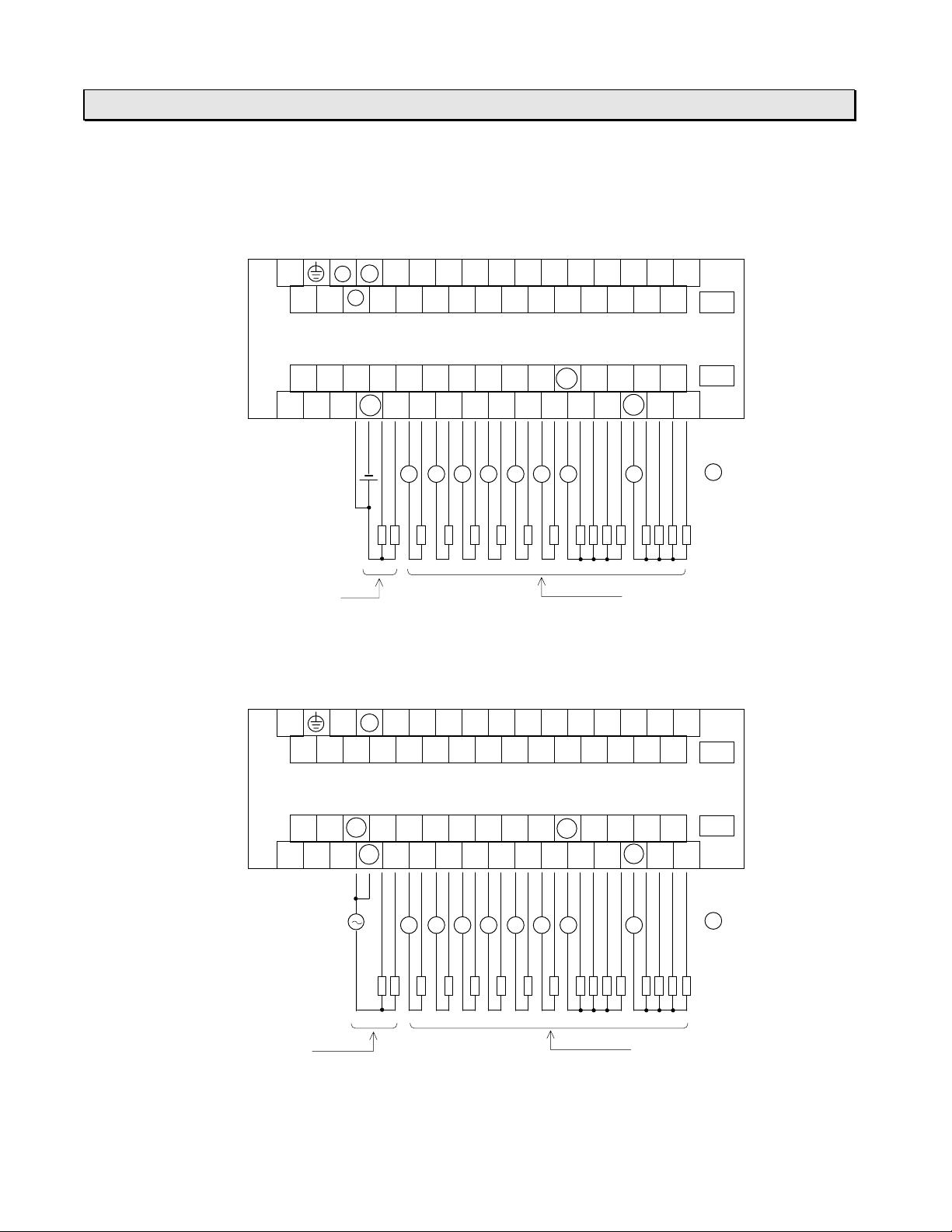
CTi Automation - Phone: 800.894.0412 - Fax: 208.368.0415 - Web: www.ctiautomation.net - Email: info@ctiautomation.net
2. Specifications
Output signal connections
····
6F3B0250
< DC input type
L
N
24 Vdc
Transistor
outputs
14 relays and 2 transistors >
----
NC
C
-
VinNCNC
NCNCNC
C0
31
20+
2220
64 CA8
2726252423
2221
PS PS
DB975
10E 161412
17151311F
IN
T1-40
OUT
C2
PSPS PS PS PS PS
2E2C2B29
2F2D
PS
240 Vac/
C1
2726252423
2A28
24 Vdc (max.)
Relay outputs
< AC input type
L
N
100 - 240 Vac
Triac
outputs
14 relays and 2 triacs >
----
NC
C
NCNC
NCNC
C0
NCNCNC
C0
31
20
64 CA8
2220
2221
PS PS PSPS PS PS PS PS
DB975
10E 161412
17151311F
IN
T1-40
2726252423
C1
2726252423
2A28
C2
OUT
2E2C2B29
2F2D
PS
240 Vac/
24 Vdc (max.)
Relay outputs
Basic Hardware and Function
59
Page 62

6F3B0250
CTi Automation - Phone: 800.894.0412 - Fax: 208.368.0415 - Web: www.ctiautomation.net - Email: info@ctiautomation.net
T1/T1S User’s Manual
60
Page 63

Section 3
CTi Automation - Phone: 800.894.0412 - Fax: 208.368.0415 - Web: www.ctiautomation.net - Email: info@ctiautomation.net
I/O Application Precautions
6F3B0250
3.1 Application precautions for input signals, 62
3.2 Application precautions for output signals, 65
Basic Hardware and Function
61
Page 64
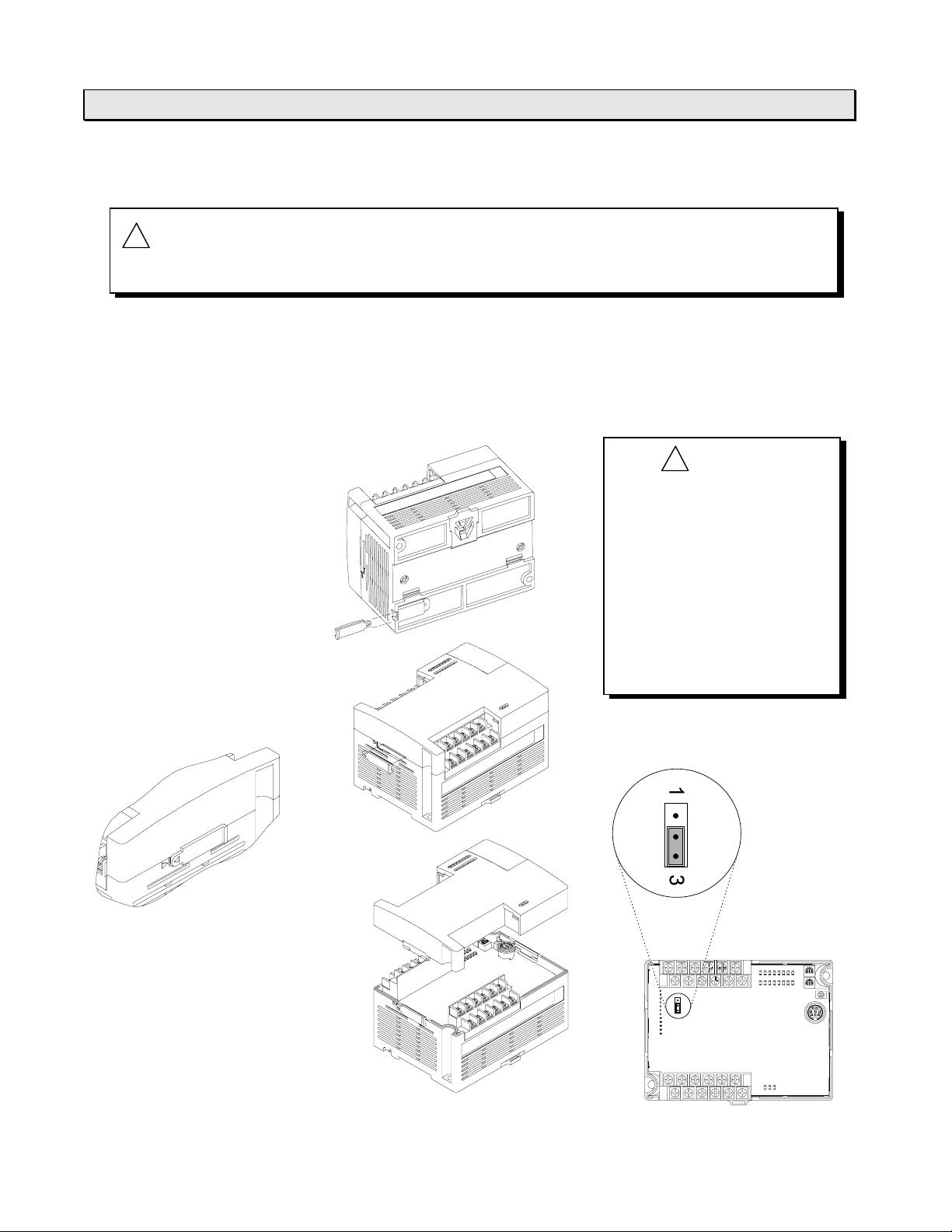
3. I/O Application Precautions
CTi Automation - Phone: 800.894.0412 - Fax: 208.368.0415 - Web: www.ctiautomation.net - Email: info@ctiautomation.net
3.1 Application precautions for input signals
6F3B0250
!
WARNING
(1) Current sour ce / sink selection on the T1-16 dry contact input
The input current flow direction (sour ce or sink) of the T1-16 dr y contact input can be
selected by setting the jumper plug on t he T1-16 printed circuit board as shown below.
The factory setting is current source. Refer to sect ion 2. 4. 1 for specifications and signal
connections.
The tool for opening the
cover is attached on the
back of the T1-16.
Remove the tool from the
unit.
Configure emergency stop and safety interlocking circuits out side t he
T1/T1S. Otherwise, malfunction of the T1/T 1S can cause injury or serious
accidents.
!
CAUTION
(1) T ur n off power before
opening the cover.
(2) T ake care not to touch
any electrical parts on
the board. Static
electricity can cause
damage.
(3) Use a pair of tweezers
to change the jumper
plug setting.
Put the tool on the side of
the unit so that the marks
<
on the tool and the unit
are aligned.
Push the tool to unhook
the cover. Then remove
the cover.
T1/T1S User’s Manual
62
Jumper plug
1 side:
Sink
3 side:
Source
Page 65

3. I/O Application Precautions
CTi Automation - Phone: 800.894.0412 - Fax: 208.368.0415 - Web: www.ctiautomation.net - Email: info@ctiautomation.net
(2) Minimum ON/O FF time of the input signal
The following conditions guarantee corr ect reading of the ON/O FF state of the input
signal:
Input ON time: ON delay time + the time for one scan
Input OFF time: OFF delay time + the tim e for one scan
The ON and OFF times of the input signals must be longer than these inter vals.
(3) Increasing t he contact current
The reliability of some contacts cannot be guaranteed by the specified input current. In
this case, install an external bleeder resistor to incr ease t he contact current.
Bleeder resistor
V
R
I
V
R
I
1
T1
input
I
2
circuit
=
II
-
Wattage
1
2
V
>´
3
R
6F3B0250
Note) The above solution cannot be applied to the T1-16 dr y contact input .
(4) Connecting tr ansistor output device
An example of connecting a transistor out put device to T1/T1S’s input circuit is shown
below.
For NPN open collector
·
n
n
T1
input
V
circuit
C
V
T1-16 dry contact input T1-28, T1-40 and T1-40S DC input
(current source)
For PNP open collector
·
+
V
C
T1
input
n
n
circuit
V
T1
input
circuit
T1
input
circuit
T1-16 dry contact input T1-28, T1-40 and T1-40S DC input
(current sink)
Basic Hardware and Function
63
Page 66
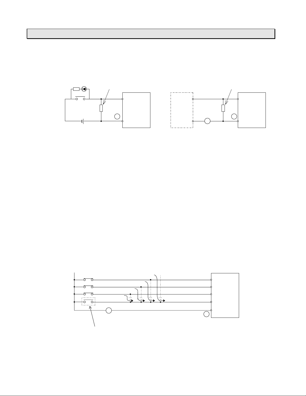
3. I/O Application Precautions
CTi Automation - Phone: 800.894.0412 - Fax: 208.368.0415 - Web: www.ctiautomation.net - Email: info@ctiautomation.net
(5) Countermeasur es against leakage current
When a switch with an LED or an AC output sensor is used, the input sometimes cannot
recognize that the switch is off due t o t he current leakage. In t his case, install a bleeder
resistor to reduce input impedance.
LED
Bleeder resistor
6F3B0250
Bleeder resistor
R
V
DC input type AC input type
Select a bleeder resistor according to t he following criteria:
(a) T he voltag e between the input terminals must be lower than the OFF voltage
when the sensor is switched off.
(b) T he cur r ent must be within the allowable range when the sensor is switched on.
(c) Calculate the wattage of the bleeder r esist or by mult iplying the current when the
sensor is switched on times three.
Note) The above solution cannot be applied to the T1-16 dr y contact input .
(6) Countermeasur es against induced current
With ac input signals, if the external cable is long or if a multi-core cable is used, an
induced current can flow from the char ged wire to the open wire, in proportion to the
capacities of the cables. In this case, sometimes the voltage reaches the level of the ON
input even though the contact is open, causing t he input to malfunction for no apparent
reason.
The usual practice when this happens is to reduce input impedance. Install a resistor or a
resistor and capacitor between the input and common terminals, or use shielded cables.
Such precautions are necessary when dealing with a large number of ac input signals.
T1
input
C
circuit
AC
output
sensor
R
V
T1
input
C
circuit
T1
input
~
V
Open contact
T1/T1S User’s Manual
64
circuit
C
Page 67
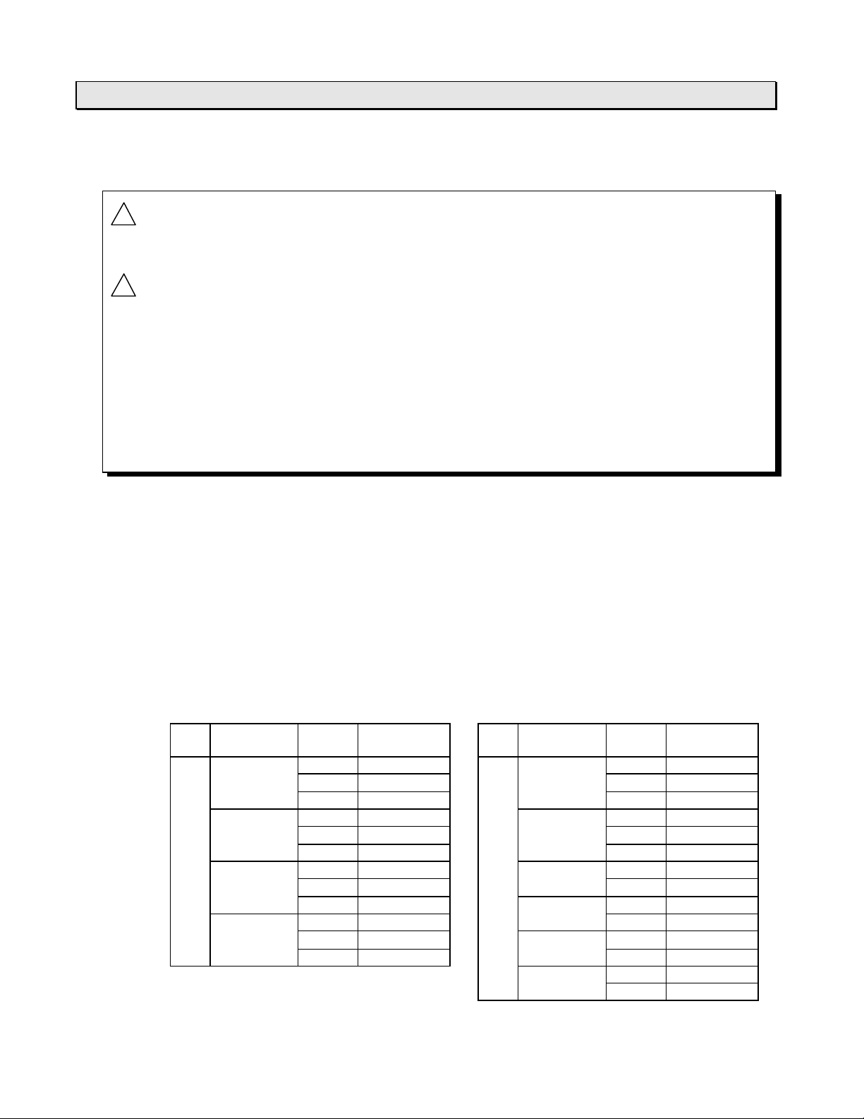
3.2 Application precautions for output signals
CTi Automation - Phone: 800.894.0412 - Fax: 208.368.0415 - Web: www.ctiautomation.net - Email: info@ctiautomation.net
6F3B0250
3. I/O Application Precautions
!
WARNING
!
CAUTION
Configure emergency stop and safety interlocking circuits outside the T1/T1S.
Otherwise, malfunction of t he T1/T1S can cause injury or serious accidents
1. Turn on power to the T1/T1S befor e t ur ning on power to the loads. Failure
to do so may cause unexpected behavior of the loads.
2. Configure the external circuit so that t he exter nal 24 Vdc power required
for the transistor output circuits and power to the loads are switched on/off
simultaneously. Also, turn off power to the loads before turning off power to
the T1/T1S.
3. Inst all fuses appropriate to the load current in the external circuits for the
outputs. Failure to do so can cause fire in case of load over-current.
(1) 2 points of solid- s t at e output
The leading 2 points of output (Y020 and Y021) are solid-state outputs, transistors on the
DC input types and triacs on the AC input types.
These solid-state outputs are suited for frequent switching applicat ions.
Note that the specifications of the solid-state outputs and other out puts (relays) are
different.
(2) Switching life of output relays
Expected relay life is more than 100,000 electrical cycles at rated maximum voltage and
current, and more than 20 million mechanical cycles. The expected contact life (electrical
cycles) is shown on the table below.
Load voltage Load
current
AC 110 Vac, 2 A 340 DC 24 Vdc, 2 A 280
load
COSf = 1
110 Vac, 2 A 150 24 Vdc, 2 A 60
COSf = 0.7
220 Vac, 2 A 220 48 Vdc, 1 A 200
COSf = 1
220 Vac, 2 A 100 L/R = 15 ms 0.2A 420
COSf = 0.7
1 A 720 load L/R = 0 ms 1 A 600
0.5 A 1,600 0.5 A 1,300
1 A 320 L/R = 15 ms 1 A 150
0.5 A 700 0.5 A 350
1 A 500 L/R = 0 ms 0.5 A 420
0.5 A 1,100 48 Vdc, 0.5 A 130
1 A 210 110 Vdc, 0.5 A 200
0.5 A 460 L/R = 0 ms 0.2 A 550
Expected life
(thousand)
Load voltage Load
current
110 Vdc, 0.2 A 150
L/R = 15 ms 0.1 A 350
Expected life
(thousand)
Basic Hardware and Function
65
Page 68
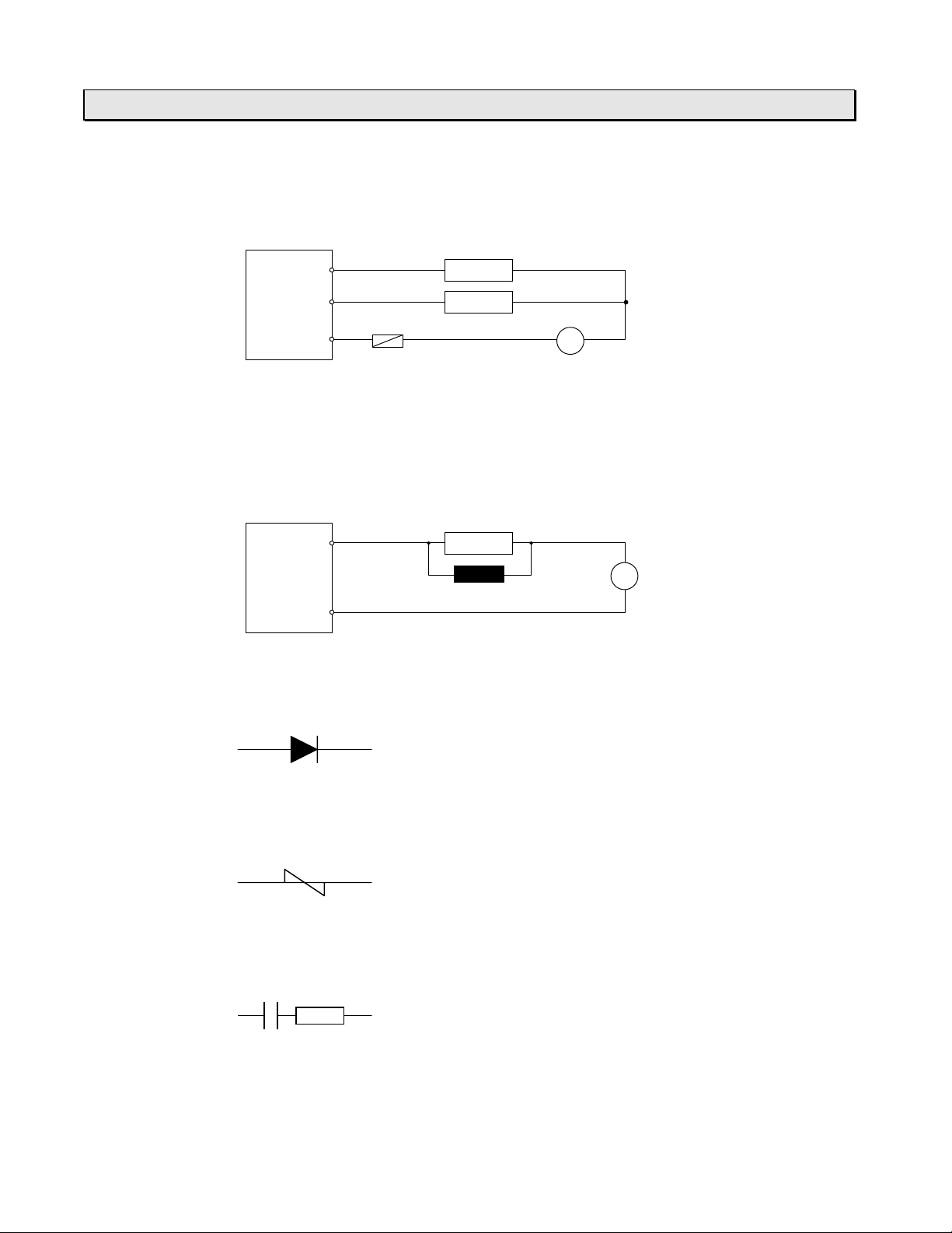
3. I/O Application Precautions
CTi Automation - Phone: 800.894.0412 - Fax: 208.368.0415 - Web: www.ctiautomation.net - Email: info@ctiautomation.net
(3) Over-curr ent protection
The output circuit of t he T1/T1S does not contain protective f uses. Fuses rated for the
output should be provided by the user.
6F3B0250
T1
output
circuit
Fuse appropriate to
the common current
(4) Output surge protection
Where an inductive load is connected t o t he output, a relatively high energy transient
voltage will be generated when the relay turns OFF. To prevent the problems caused by
this surge, install a surge absor ber in par allel t o the inductive load.
T1
output
circuit
Surge absorber:
Flywheel diode (for DC output)
·
Load
Load
PS
Load
PS
Surge absorber
Inverse withstand voltage: At least three times t hat of the power supply
Forward current: Larger than t he load cur rent
Varistor (for AC output)
·
The voltage rating is 1.2 times t he maximum (peak) voltage of t he power supply
CR snubber (for DC or AC output )
·
R: 0.5 to 1 W per volt coil voltage
C: 0.5 to 1 mF per ampere of coil current (non-polarity capacitor)
T1/T1S User’s Manual
66
Page 69

Section 4
CTi Automation - Phone: 800.894.0412 - Fax: 208.368.0415 - Web: www.ctiautomation.net - Email: info@ctiautomation.net
Installation and Wiring
6F3B0250
4.1 Environmental conditions, 68
4.2 Installing the unit, 69
4.3 Wiring term inals, 71
4.4 Grounding, 76
4.5 Power supply wiring, 78
4.6 I/O wiring, 80
Basic Hardware and Function
67
Page 70

4. Installation and Wiring
CTi Automation - Phone: 800.894.0412 - Fax: 208.368.0415 - Web: www.ctiautomation.net - Email: info@ctiautomation.net
4.1 Environmental conditions
6F3B0250
!
CAUTION
Do not install the T1/T1S in t he following locations:
·
·
·
·
·
·
·
·
Observe the following precautions when installing enclosures in which the T1/T1S will be
installed:
·
·
·
Excess temperature, humidity, vibration, shocks, or dusty and corrosive gas
environment can cause electrical shock, fir e or m alfunction.
Install and use the T1/T1S and relat ed equipment in the environment
described in this section.
Where the ambient temperature drops below 0 °C or exceeds 55 °C.
Where the relative humidity drops below 20 % or exceeds 90 %.
Where there is condensation due to sudden temperature chang es.
In locations subject to vibration that exceeds tolerance.
In locations subject to shock that exceeds toler ance.
Where there are corrosive or flammable gases.
In locations subject to dust, machining debr is or other particles.
In locations exposed to direct sunlight.
Provide the maximum possible distance from high-voltage or high-power panels. This
distance must be at least 200 mm.
If installing the enclosures in t he vicinity of high-frequency equipment , be sure to
correctly ground the enclosures.
When sharing the channel base with other panels, check for leakage current from the
other panels or equipment.
T1/T1S User’s Manual
68
Page 71

4.2 Installing the unit
CTi Automation - Phone: 800.894.0412 - Fax: 208.368.0415 - Web: www.ctiautomation.net - Email: info@ctiautomation.net
6F3B0250
4. Installation and Wiring
!
CAUTION
Installation precautions:
·
·
·
·
·
·
·
·
1. Improper installation directions or insufficient installation can cause fire
or the units to drop. Install the T1/T1S and relat ed equipment in
accordance with the instructions described in this section.
2. Turn off power before installing or removing any units, modules, rack s
or terminal blocks. Failure to do so can cause elect r ical shock or
damage to the T1/T1S and related equipment.
3. Enter ing wire scraps or ot her foreign debris into to the T1/T1S and
related equipment can cause fire or malfunction. Pay attention to prevent
entering them into the T 1 and r elat ed equipment during installation and
wiring.
NOTE
The T1/T1S basic unit and the expansion unit come equipped with a bracket at
the rear for mount ing on a 35 mm DIN rail. However, no DIN rail br acket is
provided on the expansion rack.
Because the T1/T1S is not dust-pr oof, install it in a dust-proof enclosure.
Do not install the unit directly above equipment that generates a large amount of heat,
such as a heater, transform er , or large-capacity resistor.
Do not install the unit within 200 mm of a high-voltage or high-power cables.
Allow at least 70 mm on all sides of the unit for ventilation.
For safely during maintenance and operation, install the unit as far as possible fr om
high-voltage or power equipment. Alternatively, keep the unit separate using a metal
plate or similar separator.
If a high-fr equency equipment is installed in the enclosure tog et her with the T1/T1S,
special attention is required f or grounding. See section 4.4.
Be sure to install the unit vertically with keeping the power term inals upside. Do not
install the unit horizontally or upside-down for safet y reason.
Use M4 size screws to mount the T1/T1S.
(Recommended torque: 1.47 N×m = 15 kgf×cm)
Upward
IN
PROSEC
TOSHIBA
T1
MDR40
OUT
Mount the T1 on a vertical panel.
All other mounting positions are not
acceptable.
Basic Hardware and Function
69
Page 72

4. Installation and Wiring
CTi Automation - Phone: 800.894.0412 - Fax: 208.368.0415 - Web: www.ctiautomation.net - Email: info@ctiautomation.net
Dimensions for screw mounting:
T1-16
·
113 mm
6F3B0250
2 - M4
T1-28 / T1-40 / T1- 40S / Expansion unit
·
158.5 mm
Expansion rack
·
2-slot 4-slot
2 - M4
83 mm
T1/T1S User’s Manual
70
4 - M4
149 mm
4 - M4
Page 73

4.3 Wiring terminals
CTi Automation - Phone: 800.894.0412 - Fax: 208.368.0415 - Web: www.ctiautomation.net - Email: info@ctiautomation.net
6F3B0250
4. Installation and Wiring
!
CAUTION
The terminal arrangement of each T1 Series model are shown below.
The terminal screw size is M3.5. Use crimp-style terminals of 7 mm width or less useable
for M3.5.
The terminal blocks of the T1-16 are not removable (fixed). On the other hand, the
terminal blocks of the T1-28, T1-40 and T1-40S are removable. However, be sure to turn
off power before rem oving or r eplacing the terminal blocks.
NOTE
1. Turn off power before wiring to m inim ize the risk of electrical shock.
2. Exposed conductive parts of wire can cause electrical shock. Use
crimp-style terminals with insulating sheath or insulating t ape to cover
the conductive parts. Also close the terminal covers securely on the
terminal blocks when wiring has been completed.
3. Turn off power before rem oving or replacing units, modules, term inal
blocks or wires. Failure to do so can cause electrical shock or dam age
to the T1/T1S and related equipment.
For input and output signal connections, refer to sections 2.4 and 3.
T1-16
·
T1-MDR16 ... AC power supply, Dry contact input type
6420L
T1-16
27252321
26242220
7531
C1
IN
OUT
Basic Hardware and Function
71
N
-
Vin
+
C0
Page 74
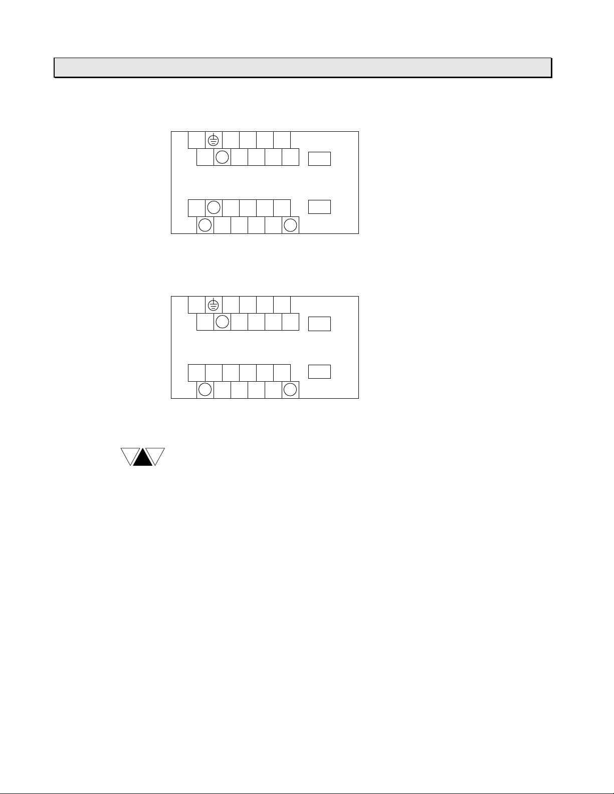
4. Installation and Wiring
CTi Automation - Phone: 800.894.0412 - Fax: 208.368.0415 - Web: www.ctiautomation.net - Email: info@ctiautomation.net
T1-MAR16 ... AC power supply, AC input type
6F3B0250
6420L
C
N
7531
IN
T1-16
NC
C0
C0
27252321
26242220
OUT
C1
T1-MDR16D ... DC power supply, DC input type
6420+
C
-
7531
IN
T1-16
OUT
C1
NOTE
VinNC
C0
27252321
26242220
NC stands for ”no connect”. Do not use t he NC terminals for wire relaying or
branching.
T1/T1S User’s Manual
72
Page 75
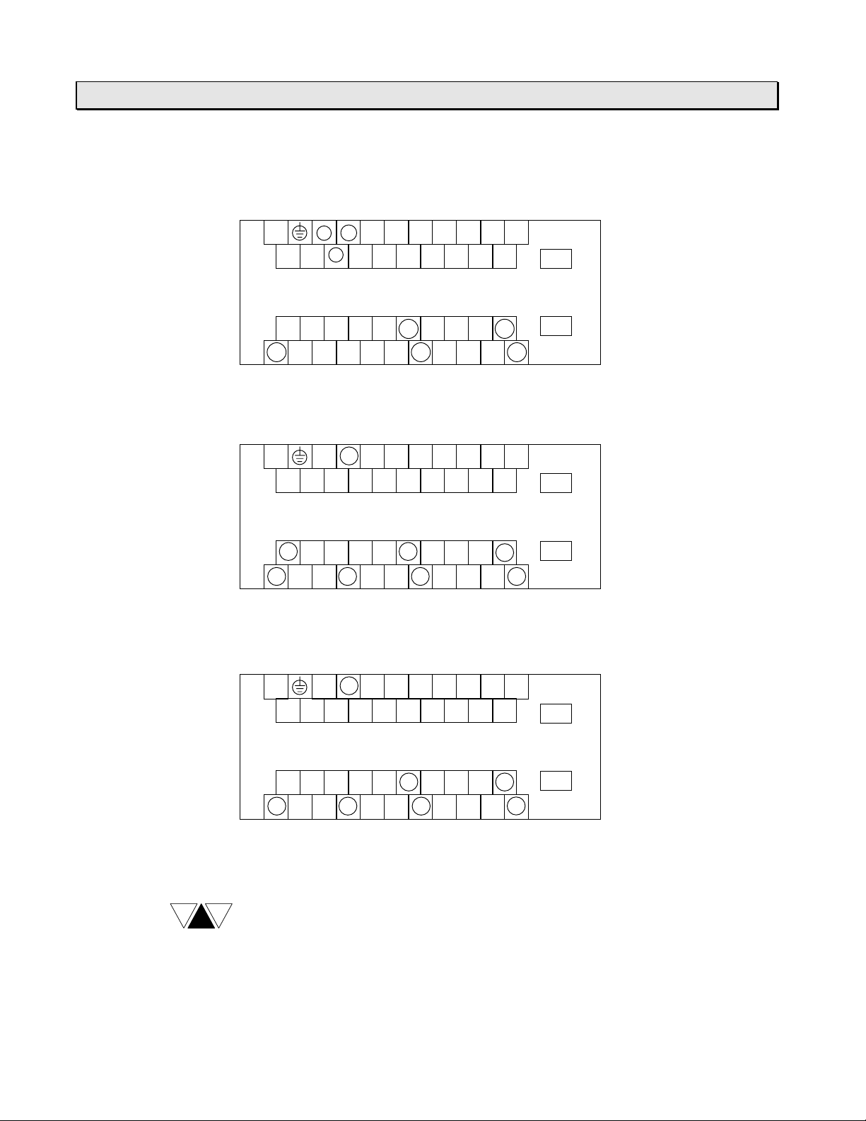
T1-28
CTi Automation - Phone: 800.894.0412 - Fax: 208.368.0415 - Web: www.ctiautomation.net - Email: info@ctiautomation.net
·
T1-MDR28 ... AC power supply, DC input type
6F3B0250
4. Installation and Wiring
NC
C
-
L
N
31
20+
64 CA8
B975
T1-28
C0
Vin
2220
C1
26242321
C2
2725
C2
2C2A28
C3
2D2B29
T1-MAR28 ... AC power supply, AC input type
NC
L
N
C
NCNC
31
20
64 CA8
B975
T1-28
C0
C0
26242321
C2
2220
C1
2725
C2
2C2A28
C3
2D2B29
D
IN
OUT
C3
D
IN
OUT
C3
T1-MDR28D ... DC power supply, DC input type
NC
+
-
C
NCNC
31
20
64 CA8
B975
T1-28
NOTE
Vin
C0
2220
NC stands for ”no connect”. Do not use t he NC terminals for wire relaying or
C1
26242321
C2
2725
C2
2C2A28
2D2B29
branching.
C3
D
IN
OUT
C3
Basic Hardware and Function
73
Page 76

4. Installation and Wiring
CTi Automation - Phone: 800.894.0412 - Fax: 208.368.0415 - Web: www.ctiautomation.net - Email: info@ctiautomation.net
T1-40
·
T1-MDR40 ... AC power supply, DC input type
6F3B0250
NC
C
-
VinNCNC
NCNCNC
C0
L
N
31
20+
2220
64 CA8
2726252423
2221
2726252423
T1-MAR40 ... AC power supply, AC input type
NC
L
N
C
NCNC
NCNC
C0
NCNCNC
C0
31
20
2220
64 CA8
2726252423
2221
2726252423
T1-MDR40D ... DC power supply, DC input type
DB975
10E 161412
17151311F
IN
T1-40
OUT
C2
2E2C2B29
2F2D
17151311F
IN
C1
2A28
DB975
10E 161412
T1-40
OUT
C2
2E2C2B29
2F2D
C1
2A28
NOTE
T1/T1S User’s Manual
74
NC
+
-
C
NCNC
31
20
64 CA8
DB975
10E 161412
17151311F
IN
T1-40
VinNCNC
NCNCNC
C0
2220
2221
2726252423
C1
2726252423
2A28
C2
OUT
2E2C2B29
2F2D
NC stands for ”no connect”. Do not use t he NC terminals for wire relaying or
branching.
Page 77

T1-40S
CTi Automation - Phone: 800.894.0412 - Fax: 208.368.0415 - Web: www.ctiautomation.net - Email: info@ctiautomation.net
·
T1-MDR40S ... AC power supply, DC input type
6F3B0250
4. Installation and Wiring
L
RXA
C
-
NC
N
Vin
TXBRXB
C0
SGTXA
31
20+
64 CA8
2220
2221
DB975
2726252423
2726252423
T1-MAR40S ... AC power supply, AC input type
NC
L
N
C
NCNC
TXBRXB
C0
SGTXARXA
C0
31
20
64 CA8
2220
2221
DB975
2726252423
2726252423
T1-MDR40SD ... DC power supply, DC input type
C1
C1
10E 161412
T1-40S
2A28
C2
10E 161412
T1-40S
2A28
C2
17151311F
IN
OUT
2E2C2B29
2F2D
17151311F
IN
OUT
2E2C2B29
2F2D
NOTE
NC
+
-
C
NCNC
31
20
64 CA8
DB975
10E 161412
17151311F
IN
T1-40S
Vin
TXBRXB
SGTXARXA
C0
2220
2221
2726252423
C1
2726252423
2A28
C2
OUT
2E2C2B29
2F2D
(1) NC stands for ”no connect”. Do not use the NC terminals for wire relaying
or branching.
(2) For t he connect ions of the RS-485 communication port (left end 5
terminals of the lower terminal block ) , r efer to the separate manual
“T1/T1S User’s Manual - Communication Function -.
Basic Hardware and Function
75
Page 78

4. Installation and Wiring
CTi Automation - Phone: 800.894.0412 - Fax: 208.368.0415 - Web: www.ctiautomation.net - Email: info@ctiautomation.net
The applicable wire size is 0.3 mm2 (22 AWG) to 1.25 mm2 (16 AWG ) . The table below
shows the recommended wire size.
Type of signal Recommended wire size
Power 1.25 mm2 (16 AWG )
Grounding 1.25 mm2 (16 AWG )
I/O signals 0.3 mm2 (22 AWG) to 0.75 mm2 (18 AWG )
4.4 Grounding
6F3B0250
!
CAUTION
The optimum method for grounding electronic equipment is to ground it separ at ely fr om
other high-power systems, and to ground m or e than one units of electronic equipment
with a single-point ground.
Although the T1/T1S has noise immunity to be used in industrial operating conditions,
grounding is important for safety and reliability.
Check the grounding against the following criteria.
1. The T1/T1S must not become a path for a ground current. A high-frequency current is
2. Equalize the ground potentials when the expansion rack or unit is connected. Ground
3. Do not connect t he ground of the T1/T1S to that of high- power systems.
4. Do not use a ground that has an unstable impedance, such as painted screws, or
1. Turn off power before wiring to m inim ize the risk of electrical shock.
2. Oper at ion without grounding may cause electrical shock or malfunction.
Connect the ground terminal on the T 1/T1S to the system ground.
particularly harmful.
the T1/T1S and the expansion rack or unit at a single point.
ground subject to vibration.
The grounding marked terminal (see below) is provided on the T1/T1S basic unit and the
expansion unit for grounding purpose.
T1/T1S User’s Manual
76
Page 79

6F3B0250
CTi Automation - Phone: 800.894.0412 - Fax: 208.368.0415 - Web: www.ctiautomation.net - Email: info@ctiautomation.net
4. Installation and Wiring
In case of the expansion rack is connected to t he T1/T1S, the rack m ount ing screw is
used for this purpose.
Expansion rack
T1
Mounting panel
System ground
1.25 mm
·
rack/unit with the enclosure grounding bus bar .
100 W or less to ground is required.
·
2
(16 AWG) wire should be used to connect the T1/T1S and the expansion
Basic Hardware and Function
77
Page 80

4. Installation and Wiring
CTi Automation - Phone: 800.894.0412 - Fax: 208.368.0415 - Web: www.ctiautomation.net - Email: info@ctiautomation.net
4.5 Power supply wiring
6F3B0250
!
CAUTION
Wire the power source t o t he T1/T1S power supply terminals.
Power source
Power conditions:
·
1. Turn off power before wiring to m inim ize the risk of electrical shock.
2. Applying excess power voltage to the T1/T1S can cause explosion or fire.
Apply power of the specified ratings described below.
Line filter
Insulation
transformer
T1
AC power supply type DC power supply type
Rated voltage 100 to 240 Vac, +10/-15 % 24 Vdc, +20/-15 %
Frequency
Power consumption 30 VA or less (T1-16/T1-28)
Retentive power
interruption
1.25 mm
·
The power cable should be separated from other cables.
·
2
(16 AWG) twisted-pair cable should be used for the power cable.
50/60 Hz, ±5 %
38 VA or less (T1-40)
45 VA or less (T1-40S)
Continuous operation for less than 10 ms
12 W or less (T1-16/T1-28)
18 W or less (T1-40)
18 W or less (T1-40S)
-
T1/T1S User’s Manual
78
Page 81
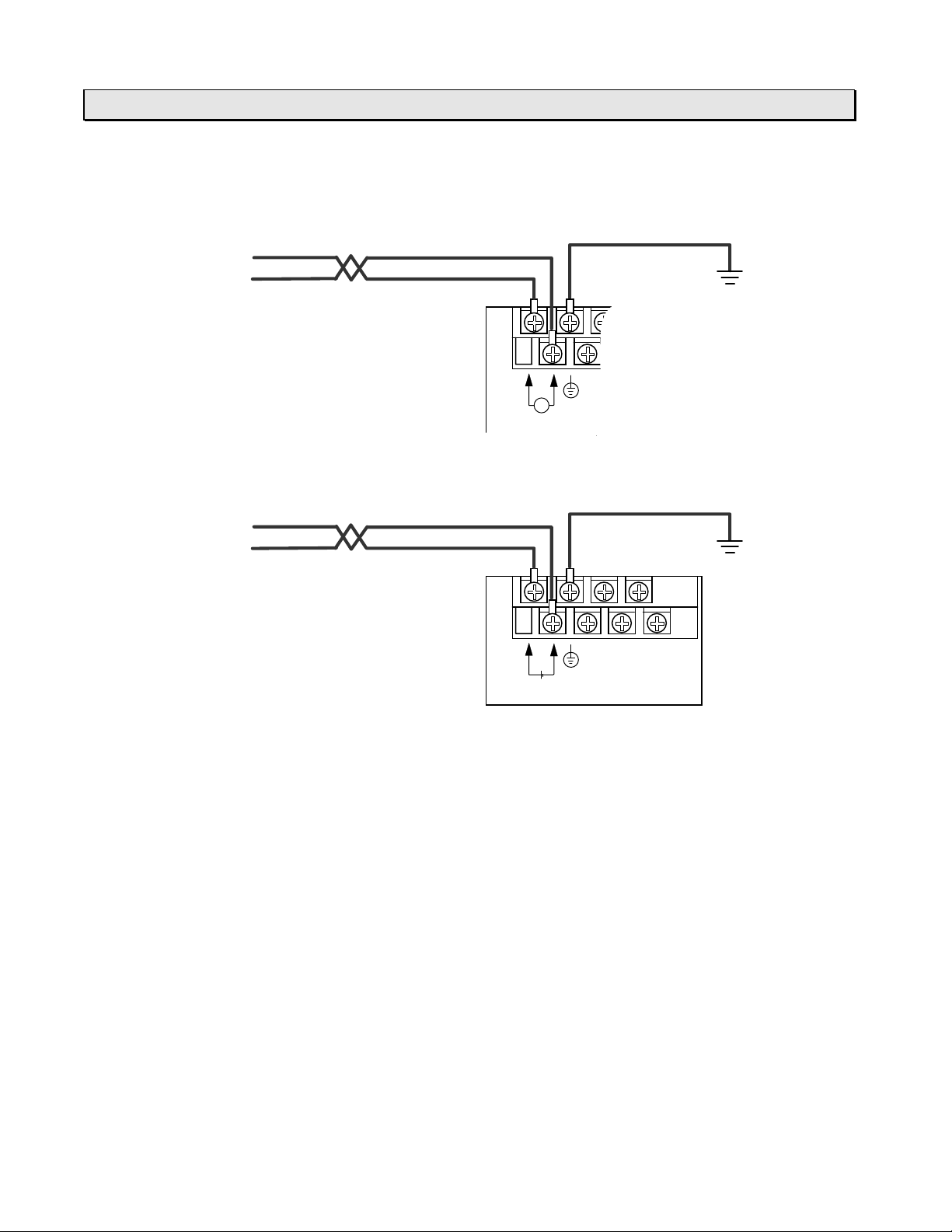
Connections of the power supply terminals are shown below.
CTi Automation - Phone: 800.894.0412 - Fax: 208.368.0415 - Web: www.ctiautomation.net - Email: info@ctiautomation.net
AC power supply type
·
100 to 240 Vac
DC power supply type
·
6F3B0250
4. Installation and Wiring
Grounding
NL
~
100-240VAC
24 Vdc
-
+
Grounding
-+
24Vdc
Basic Hardware and Function
79
Page 82

4. Installation and Wiring
CTi Automation - Phone: 800.894.0412 - Fax: 208.368.0415 - Web: www.ctiautomation.net - Email: info@ctiautomation.net
4.6 I/O wiring
6F3B0250
!
CAUTION
·
·
·
·
·
1. Turn off power before wiring to m inim ize the risk of electrical shock.
2. Exposed conductive parts of wire can cause electrical shock. Use
crimp-style terminals with insulating sheath or insulating tape to cover the
conductive parts. Also close the terminal covers securely on the terminal
blocks when wiring has been completed.
3. Turn off power before rem oving or replacing units, modules, term inal
blocks or wires. Failure to do so can cause electrical shock or damage to
the T1/T1S and related equipment.
Refer to sections 2.4 and 3 for instructions on how to properly wire the I/O terminals.
0.75 mm
Separate the I/O signal cables from high-power cables by at least 200 mm.
If expansion rack or unit is used, separate the expansion cable from the power and I/O
signal cables by or unit at least 50 mm.
It is recommended to separate the input signal cables from output signal cables.
2
(18 AWG) to 0.3 mm2 (22 AWG) wires are recommended for I/O signals.
signal
200mm
or more
High-power
cable
T1
Input signal
T1/T1S User’s Manual
80
Output
Page 83

Section 5
CTi Automation - Phone: 800.894.0412 - Fax: 208.368.0415 - Web: www.ctiautomation.net - Email: info@ctiautomation.net
Operating System Overview
6F3B0250
5.1 Operation modes, 82
5.2 About the built-in EEPROM, 84
5.3 Scanning, 87
Basic Hardware and Function
81
Page 84

5. Operating System Overview
CTi Automation - Phone: 800.894.0412 - Fax: 208.368.0415 - Web: www.ctiautomation.net - Email: info@ctiautomation.net
5.1 Operation modes
The T1/T1S has three basic operation modes, the RUN mode, the HALT m ode and t he
ERROR mode. The T1/T1S also has the HOLD and RUN-F modes mainly for system
checking.
6F3B0250
RUN:
HALT:
ERROR:
The RUN mode is a normal control-oper ation mode.
In this mode, the T1/T 1S reads external signals, executes the user program
stored in the RAM, and outputs signals to the external devices according to the
user program. It is in the RUN mode that the T1/T1S performs scans the user
program logic, which is the basic operation of a PLC.
In case of the T1S, program changes and EEPROM write are possible while
the T1S is in the RUN mode. Ref er to section 6.9.
On the other hand, in case of the standard T1, program changes and
EEPROM write are not possible in the RUN mode.
The HALT mode is a programm ing mode.
In this mode, user program execution is st opped and all out puts are switched
off.
Program loading into t he T1/T1S is possible only in the HALT mode.
For the standard T1, prog r am changes and EEPROM write are possible only
when the T1 is in the HALT mode.
The ERROR mode is a shut-down mode as a result of self-diagnosis.
The T1/T1S enters the ERROR mode if internal t r ouble is det ected by selfdiagnosis. In this mode, prog r am execution is st opped and all outputs are
switched off. The cause of the shut-down can be confirmed by connecting the
programming tool.
To exit from the ERRO R m ode, execute t he Error Reset command from the
programming tool, or cycle power off and then on again.
HOLD:
RUN-F:
T1/T1S User’s Manual
82
The HOLD mode is provided mainly for checking the external I/O signals.
In this mode, user program execution is st opped, with input and out put
updating is executed. It is therefore possible to suspend program execution
while holding the output state. Moreover, a desired output state can be
established by setting any data by using the programm ing tool.
The RUN-F mode is a forced RUN m ode pr ovided for program check ing.
This mode is effective when using the expansion I/Os.
Deferent from the normal RUN mode, the RUN-F mode allows operation even
if the registered option cards, expansion unit and/or I/O modules are not
actually mounted.
Page 85

6F3B0250
CTi Automation - Phone: 800.894.0412 - Fax: 208.368.0415 - Web: www.ctiautomation.net - Email: info@ctiautomation.net
5. Operating System Overview
The operation modes are switched by the mode control switch provided on the T1/ T1S
and the mode control commands issued fr om t he pr ogramming tool.
The mode transition conditions are shown below.
(Power ON)
’
HOLD
RUN
‘
Œ
Ž
•
Ž
•
HALT
•
’
Œ
•
Ž
•
•
‘
’
“
‘
RUN-F
ERROR
Mode control switch is in R (RUN) side.
Mode control switch is in H (HALT) side.
Mode control switch is turned to H (HALT) side, or HALT command is issued from
the programming tool.
Mode control switch is turned to R (RUN) side, or RUN comm and is issued from
the programming tool.
Force RUN (RUN-F) command is issued from the programm ing tool.
HOLD command is issued from the pr ogramming tool.
HOLD Cancel command is issued from the pr ogramming tool.
Error Reset command is issued from the programming t ool.
(dotted line) Error is detected by self-diagnosis.
Ž
“
NOTE
The commands from the pr ogramming tool are available when the mode
control switch is in R (RUN) side.
Basic Hardware and Function
83
Page 86

5. Operating System Overview
CTi Automation - Phone: 800.894.0412 - Fax: 208.368.0415 - Web: www.ctiautomation.net - Email: info@ctiautomation.net
5.2 About the built-in EEPROM
The T1/T1S is equipped with a built-in EEPROM and a RAM as standard feat ur es.
The user program is stored in the EEPROM so that the user program can be maintained
without the need of a battery. A part of the Data register can also be stor ed in t he
EEPROM.
The table below shows the contents stored in the built-in EEPROM.
User program Entire program (2 k steps) and
System information
User data Leading 512 words of Data
register (fixed).
D0000 - D0511
Other data
T1 T1S
Entire program (8 k steps) and
System information
User specified number of Data
register starting with address
0. It is set by SW55.
D0000 - Dnnnn
(up to 2048 words)
-
SW36 - SW38:
Programmer port settings
SW55:
Number of Data register to
be saved in the EEPROM
SW56 - SW57:
RS-485 port settings
6F3B0250
The user program and the data stored in the EEPROM is transferred to the RAM when
power is turned on. Subsequent program execution is done based on the RAM contents.
Program editing is also performed on the RAM contents.
Therefore, if the program is modified, i t i s necessary t o i ssue t he EEPRO M Wri t e
command from the programming tool. Otherwise, the modified program is overwritten by original EEPROM contents when the power is turned off and on agai n.
T1/T1S User’s Manual
84
Page 87

< T1 >
CTi Automation - Phone: 800.894.0412 - Fax: 208.368.0415 - Web: www.ctiautomation.net - Email: info@ctiautomation.net
6F3B0250
5. Operating System Overview
and System info
< T1S >
and System info
EEPROM
User program
(2 k steps)
Data register
(512 words)
EEPROM
User program
(8 k steps)
•
‚
•
RAM
User program
(2 k steps)
and System info
Data register
(D0000 to D0511)
Data register
(D0512 to D1023)
and
other registers
RAM
User program
(8 k steps)
and System info
‚
Data register
(0 to 2048 words,
user setting)
When power is turned on ( it is called initial load) or EEPROM Read command is
•
issued from the programming tool. The EEPROM Read is possible only in the HALT
mode.
When EEPROM Write command is issued from the programming tool. It is possible
‚
only in the HALT mode (T1), or in other than the ERROR mode (T 1S) .
Basic Hardware and Function
Data register
(D0000 to Dnnnn,
user setting)
Other dataOther data
The rest of Data
register and
other registers
85
Page 88

5. Operating System Overview
CTi Automation - Phone: 800.894.0412 - Fax: 208.368.0415 - Web: www.ctiautomation.net - Email: info@ctiautomation.net
In case of the T1S, Special register SW55 is used to specify the number of Data registers
to be stored in the EEPROM. The allowable setting value is 0 to 2048.
The table below shows the correspondence between the SW55 value and Data registers
saved in the EEPROM.
6F3B0250
SW55 sett ing
value
0 None
1 D0000 only
2 D0000 to D0001
3 D0000 to D0002
::
2047 D0000 t o D2046
2048 D0000 t o D2027 Default value
Others D0000 to D2027 Regarded as 2048
When the EEPROM Write command is executed, the T1S checks the value of SW55 and
saves the Data registers into the EEPROM depending on the SW55 value. The value of
SW55 itself is also saved in the EEPROM.
At the initial load or the EEPROM Read command is executed, the T1S checks the value
for SW55 in the EEPROM and transfers the corr esponding number of data to the Dat a
registers of the RAM.
NOTE
(1) T he EEPROM has the life limit for writing. It is 100,000 times. Pay
(2) I n t he T1S, if the EEPROM Write command is executed in RUN mode,
(3) T he dat a in the EEPROM (D0000 to D0511 or D0000 to D2047) can also
(4) T he SW55 sett ing is available only for the T1S.
Range of Data register s saved in
EEPROM
attention not to exceed the limit. If the number of execution of EEPROM
Write command exceeds 100,000 times, EEPROM alarm flag (S007)
comes ON.
only the user program is written into the EEPROM.
be read or written by using the program inst ruction (FUN236 XFER
instruction).
Remarks
T1/T1S User’s Manual
86
Page 89
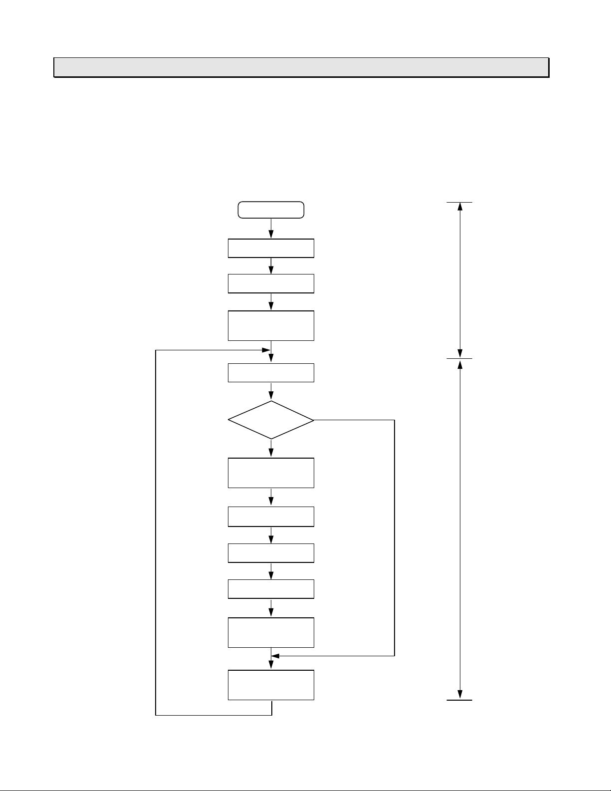
5.3 Scanning
CTi Automation - Phone: 800.894.0412 - Fax: 208.368.0415 - Web: www.ctiautomation.net - Email: info@ctiautomation.net
The flowchart below shows the basic internal operations perform ed by the T1/T1S from
the time power is turned on through prog r am execution. As the diagram shows,
executing a program consists of continuous scanning operations. One scan is a cycle
starting with the self-diagnosis and ending with the completion of peripheral support.
Power ON
Hardware check
Initial load
Register/device
initialization
6F3B0250
5. Operating System Overview
Power-up
initialization
(approx. 1 s)
Scan
Self-diagnosis
Mode
control
RUN mode
Register/device
initialization
Program check
I/O update
Timer update
User program
execution
HALT mode
At the first
scan
At the first
scan
Scan cycle
Peripheral
support
Basic Hardware and Function
87
Page 90

5. Operating System Overview
CTi Automation - Phone: 800.894.0412 - Fax: 208.368.0415 - Web: www.ctiautomation.net - Email: info@ctiautomation.net
Hardware check:
Performs checking and init ialization of the system ROM, the system RAM and the
peripheral LSIs.
Initial load:
Transfers the user pr ogram and user data from the EEPROM to the RAM. (Refer to
section 5.2)
Register/device initialization:
Initializes registers and devices as shown below.
Register/device Initialization
External input (X/XW) Forced inputs are ret ained. Others are cleared to 0.
External output (Y/YW) Forced coil devices are retained. Others are cleared to 0.
Auxiliary device/register
(R/RW)
Special device/register
(S/SW)
Timer device/register
(T./T)
Counter device/register
(C./C)
Data register (D) User specified retentive registers ar e r etained. Others are
Index register (I, J, K) Cleared to 0.
6F3B0250
User specified retentive register s and forced coil devices
are retained. Others are cleared t o 0.
Special setting data are retained. O t her s are cleared to 0.
User specified retentive register s ar e r et ained. Others are
cleared to 0.
User specified retentive register s ar e r et ained. Others are
cleared to 0.
cleared to 0.
NOTE
(1) When the data stor ed in t he EEPRO M (Data registers) are used, these
registers should be specified as retent ive. O therwise, these data are
transferred fr om EEPROM to RAM, but then cleared to 0 at the
initialization.
(2) T he dat a in t he retentive registers are stored in RAM and backed up by
built-in capacitor. The back-up period is 6 hours or more at 25 °C (T1), or
168 hours or more at 25 °C (T1S).
The T1/T1S checks t he validity of t he retentive data at the power-up
initialization, and if they are not valid, sets the special device (S00F) to ON.
Therefore, it is recommended to check the status of S00F in the user
program and to initialize the retentive registers if S00F is O N.
(3) T he r et entive registers can be set by the programm ing tool for RW, T, C
and D registers. The reg ist er s from address 0 to the designat ed addr ess
for each type are set as retentive reg ist er s. Refer to the separate manual
for the programm ing tool for setting t he retentive registers.
(4) T he input force and the forced coil are functions for progr am debugging.
For details, refer to sect ion 6. 7.
T1/T1S User’s Manual
88
Page 91

6F3B0250
CTi Automation - Phone: 800.894.0412 - Fax: 208.368.0415 - Web: www.ctiautomation.net - Email: info@ctiautomation.net
5. Operating System Overview
Self-diagnosis:
Checks the proper operation of the T1/T1S itself. If an error has detected and cannot be
recovered by re-tries, the T1/ T1S moves into ERROR mode. For the self-diagnosis
items, refer to sect ion 10. 2.
Mode control:
Checks the mode control switch status and the m ode cont r ol r equest commands from
the programming tool.
The scan mode - floating scan or fixed-time scan - is also controlled hear.
NOTE
The floating scan:
When one scan is finished, immediately starts the next scan. The scan time is
shortest, but may vary depending on the program execution status.
Scan timeScan time Scan time
The fixed-time scan:
The scan operation is started every user-specified time. The time setting range
is 10 to 200 ms (10 ms units). If an actual scan needs longer time than t he
setting time, it works as the floating scan.
Scan time (50 ms fixed) Scan time (50 ms fixed)
(idling) (idling)
Program check:
At the beginning of the RUN mode, the user progra m is com p iled and it s validity is
checked.
I/O update:
Reads the external input signals into the external input devices/registers (X/XW), and
sends the data of the external output devices/registers (Y/YW) to the external output
circuits. Then the outputs ( r elays, etc. ) changes the states and latches until the next I/O
update timing.
The states of the forced input devices are not updated by this operation.
Timer update:
Updates the timer registers which are activated in the user pr ogram, and the timing
devices (S040 to S047).
Basic Hardware and Function
89
Page 92

5. Operating System Overview
CTi Automation - Phone: 800.894.0412 - Fax: 208.368.0415 - Web: www.ctiautomation.net - Email: info@ctiautomation.net
User program execution:
Executes the programmed instructions from the beginning t o t he END instruction.
This is the essential function of t he T1/T1S.
In this section, only the main program execution is mentioned. For other program types,
such as timer interrupt, etc., refer to section 6.5.
Peripheral support:
Supports the communications with the program m ing tool or an external devices
connected by the computer link funct ion. The time for this operat ion is lim it ed within
approx. 2 ms in the floating scan mode, and within allowable idling time in the fixed-time
scan mode.
In case of the T1S, if the special relay S158 is set to ON, the peripheral support priority
mode is selected. In the peripheral support pr iority mode, the peripheral support time is
not limited. As the result, t he com m unicat ion r esponse is im pr oved although the scan
time becomes long at the time.
6F3B0250
T1/T1S User’s Manual
90
Page 93

Section 6
CTi Automation - Phone: 800.894.0412 - Fax: 208.368.0415 - Web: www.ctiautomation.net - Email: info@ctiautomation.net
Programming Information
6F3B0250
6.1 Devices and registers, 92
6.2 Index modification, 104
6.3 Real-time clock/calendar, 106
6.4 I/O allocation, 107
6.5 T1S memory mode setting, 109
6.6 User program configuration, 110
6.7 Programming language, 116
6.8 Program execution sequence, 117
6.9 On-line debug support functions, 118
6.10 Password pr otection, 121
Basic Hardware and Function
91
Page 94

6. Programming Information
CTi Automation - Phone: 800.894.0412 - Fax: 208.368.0415 - Web: www.ctiautomation.net - Email: info@ctiautomation.net
6.1 Devices and registers
The T1/T1S program consists of bit-based instructions that handle ON/OFF information,
such as contact and coil instructions, and regist er - based ( 16-bit) instructions, such as
those for data transfer and arithmetic operations.
Devices are used to store the ON/OFF infor m at ion of contacts and coils, and register s
are used to store 16-bit data.
Devices are divided into six types:
X External input devices
Y External out put devices
R Auxiliary relay devices
S Special devices
T. Timer devices
C. Counter devices
6F3B0250
Registers are divided into eight types:
XW External input registers
YW External output registers
RW Auxiliary relay registers
SW Special registers
T Timer registers
C Counter r egisters
D Data r egisters
I, J, K Index registers
Device and register numbers
X devices share the same memory area as XW registers. Device X014, for example,
represents the number 4 bit in the X W01 regist er .
Bit position / Number
(MSB) (LSB)
FEDCBA9876543210
XW01 1
X014
Thus, "X014 is ON" means that bit number 4 of XW01 is 1.
Y, R, and S devices work in a similar manner.
T1/T1S User’s Manual
92
Page 95

6F3B0250
CTi Automation - Phone: 800.894.0412 - Fax: 208.368.0415 - Web: www.ctiautomation.net - Email: info@ctiautomation.net
6. Programming Information
Addressing devices
A device number of X, Y, R and S devices consists of a register number and bit position
as follows.
X 01 4
Represents bit position 0 to F in the regist er .
Decimal number representing the r egister containing the corresponding
device.
Represents the type of device. (X, Y, R, or S)
As for the timer (T . ) and the counter (C.) devices, a device number is expressed as
follows.
T. 12
Corresponding register number . ( decimal number)
Represents the type of device. (T. or C. )
Dot (.) is used to identify as device.
Addressing registers
A register number except the index register s is expressed as follows.
XW 01
Register number. (decimal number )
Represents the type of reg ist er . ( XW, YW, RW, SW, T, C or D)
The index registers (I, J and K) do not have the num ber .
J
I, J, or K
Basic Hardware and Function
93
Page 96

6. Programming Information
CTi Automation - Phone: 800.894.0412 - Fax: 208.368.0415 - Web: www.ctiautomation.net - Email: info@ctiautomation.net
Available address range
Device/register Symbol T1 T1S
External input
device
External output
device
External input
register
External output
register
Auxiliary relay
device
Auxiliary relay
register
Special device S 1024
Special register SW 64 words SW00 - SW 63 64 words SW00 - SW 63
Timer device T. 64 points T. 00 - T.63 256 points T.000 - T.255
Timer register T 64 words T00 - T63 256 words T000 - T255
Counter device C. 64 points C.00 - C.63 256 points C.000 - C. 255
Counter register C 64 words C00 - C63 256 words C000 - C255
Data register D 1024
Index register I 1 word I (no address) 1 word I (no address)
X Total 512
Y Y020 - Y31F Y020 - Y31F
XW Total 32
YW YW02 - YW31 YW02 - YW31
R 1024
RW 64 words RW00 - RW 63 256 words RW000 -
J 1 word J (no address) 1 word J (no address)
K 1 word K (no address) 1 word K (no address)
Number of
points
points
words
points
points
words
Address range Number of
points
X000 - X31F Total 512
points
XW00 - XW31 Total 32
words
R000 - R63F 4096
points
S000 - S63F 1024
points
D0000 - D1023 4096
words
6F3B0250
Address range
X000 - X31F
XW00 - XW31
R000 - R255F
RW255
S000 - S63F
D0000 - D4095
NOTE
T1/T1S User’s Manual
94
(1) 1 word = 16 bits
(2) T he available data range in each register is -32768 to 32767 (H8000 to
H7FFF) except for the timer and the count er registers.
The data range of the timer register is 0 to 32767. T hat of the counter
register is 0 to 65535.
(3) Double-word (32 bits) data is available in two consecutive registers.
In this case, lower address register stores the lower 16 bits data.
(MSB) F 0 F 0 (LSB)
D0100D0101
Upper Lower
16 bits 16 bits
In this manual, a double-word register is expressed by using ‘×’.
For example, D0101×D0100.
Page 97

6F3B0250
CTi Automation - Phone: 800.894.0412 - Fax: 208.368.0415 - Web: www.ctiautomation.net - Email: info@ctiautomation.net
6. Programming Information
External input devices (X)
These devices (X) indicate the ON/OFF states of external input signals through the input
circuits. External input devices can be used many times in a program .
External output devices (Y)
The external output devices (Y) store the ON/OFF signals that drive the external devices
through the output circuits . They can be used for coils in a program.
External input registers (XW)
These (XW) are 16-bit register s for storing values which are received from the input
circuits.
External output registers (YW)
These 16-bit registers (YW) are used for storing values which are sent to the output
circuits.
Auxiliary relay devices and registers (R/RW)
The auxiliary relay devices (R) are used to store intermediate results of sequences. The
auxiliary relay registers (RW) are used to store temporary results of function instructions.
The data in R/RW cannot be output directly to the output circuits. It is necessary to move
the data to Y/YW.
It is possible to make these reg ist er s r etentive so that they retain data in the event of a
power failure. See section 5.3.
Timer devices and registers (T./T)
The timer registers (T) are used for storing the elapsed time of timer inst r uctions, the
on-delay (TON), off-delay (TOF) and single- s hot ( SS) timers.
0.01 s base timers and 0.1 s base timers are pr ovided.
Time base T1 T 1S
0.01 s T000 to T031 T000 to T063
0.1 s T032 to T063 T064 to T255
The timer devices (T.) works as the output of the timer instr uctions.
It is possible to specify the T reg ist er s as r etentive to retain their data in the event of a
power failure. See section 5.3.
Basic Hardware and Function
95
Page 98

6. Programming Information
CTi Automation - Phone: 800.894.0412 - Fax: 208.368.0415 - Web: www.ctiautomation.net - Email: info@ctiautomation.net
Counter devices and registers (C./C)
The counter registers (C) are used for storing the count value of the counter (CNT) and
the up-down counter (U/D) instructions.
The counter devices (C.) works as the output of the counter instructions.
It is possible to specify the C register s as r etentive to retain their data in the event of a
power failure. See section 5.3.
Data registers (D)
Functionally the data registers (D) are the same as auxiliary relay registers (RW) except
that the D registers cannot be used as devices.
A part of the data reg isters are saved in the built-in EEPROM as fixed data and
transferred into t he RAM at the initial load. See section 5.2.
Range of the data regist er s saved in the EEPRO M:
T1 T1S
D0000 to D0511 User specified range
6F3B0250
starting with D0000
(up to 2048 words)
It is possible to specify the D register s as r etentive to retain their data in the event of a
power failure. See section 5.3.
Index registers (I, J, and K)
These index registers are used for indir ect addressing for a reg ister.
For example, if the value of I is 100 in the following register expression, it designat es
D0100. For details, refer t o sect ion 6.2.
I
D0000 D0100 if I=100
T1/T1S User’s Manual
96
Page 99

6F3B0250
g
CTi Automation - Phone: 800.894.0412 - Fax: 208.368.0415 - Web: www.ctiautomation.net - Email: info@ctiautomation.net
6. Programming Information
Special devices and registers (S/SW)
The special devices (S) and special registers (SW) are used for special pur poses. See
list below.
Device/
ister
re
S000 0: Initialization4: HOLD mode
S001 T1/T1S operation mode 1: HALT mode 6: ERROR mode
S002 2: RUN mode
S003 3: RUN-F mode
S004 CPU error (down) ON at error state (related to SW01)
S005 I/O error (down) ON at error state (related to SW02)
S006 Program error (down) ON at error state (related to SW03)
S007 EEPROM alarm (alarm) ON when EEPROM write exceeds 100,000 times
S008 Fixed-time scan time-over
(alarm)
S009
S00A Clock/calendar error
(alarm)
S00B
S00C
S00D TL-F10 error (alarm) ON when TOSLINE-F10 transmission error occurs
S00E
S00F Retentive data invalid
(alarm)
NOTE
(1) These devices are set by the T1/T1S operating system. These devices are
Name Function
ON when actual scan time is longer than the setting time
as fixed-time scan
-
-
-
-
Reserved
ON when clock/calendar data is illegal (T1S only)
Reserved
Reserved
Reserved
ON when retentive data in RAM are invalid
read only for user.
(2) Devices mark ed as (down) are set in the ERROR mode. Therefore these
devices cannot be used in the user program.
(3) Devices marked as (alarm) are set in the normal operation mode. These
devices can be used in the user program.
Basic Hardware and Function
97
Page 100

6. Programming Information
g
CTi Automation - Phone: 800.894.0412 - Fax: 208.368.0415 - Web: www.ctiautomation.net - Email: info@ctiautomation.net
6F3B0250
Device/
ister
re
S010 System ROM error (down) ON at error state
S011 System RAM error (down) ON at error state
S012 Program memory error
(down)
S013 EEPROM error (down) ON at error state
S014
S015
S016
S017
S018
S019
S01A
S01B
S01C
S01D
S01E
S01F Watchdog timer error
(down)
S020 I/O bus error (down) ON at error state (for T2 I/O modules)
S021 I/O mismatch (down) ON at error state
S022 I/O no answer (down) ON at error state (for T2 I/O modules)
S023 I/O parity error (down) ON at error state (for T2 I/O modules)
S024
S025
S026
S027
S028
S029
S02A
S02B
S02C
S02D
S02E
S02F
Name Function
ON at error state
-
-
-
-
-
-
-
-
-
-
-
-
-
-
-
-
-
-
-
-
-
-
-
Reserved
Reserved
Reserved
Reserved
Reserved
Reserved
Reserved
Reserved
Reserved
Reserved
Reserved
ON at error state
Reserved
Reserved
Reserved
Reserved
Reserved
Reserved
Reserved
Reserved
Reserved
Reserved
Reserved
Reserved
NOTE
(1) These devices are set by the T1/T1S operating system. These devices are
read only for user.
(2) Devices mark ed as ( down) are set in the ERROR mode. Therefor e t hese
devices cannot be used in the user program.
T1/T1S User’s Manual
98
 Loading...