

Toshiba 57HLX82 User Manual
OWNER'S MANUAL
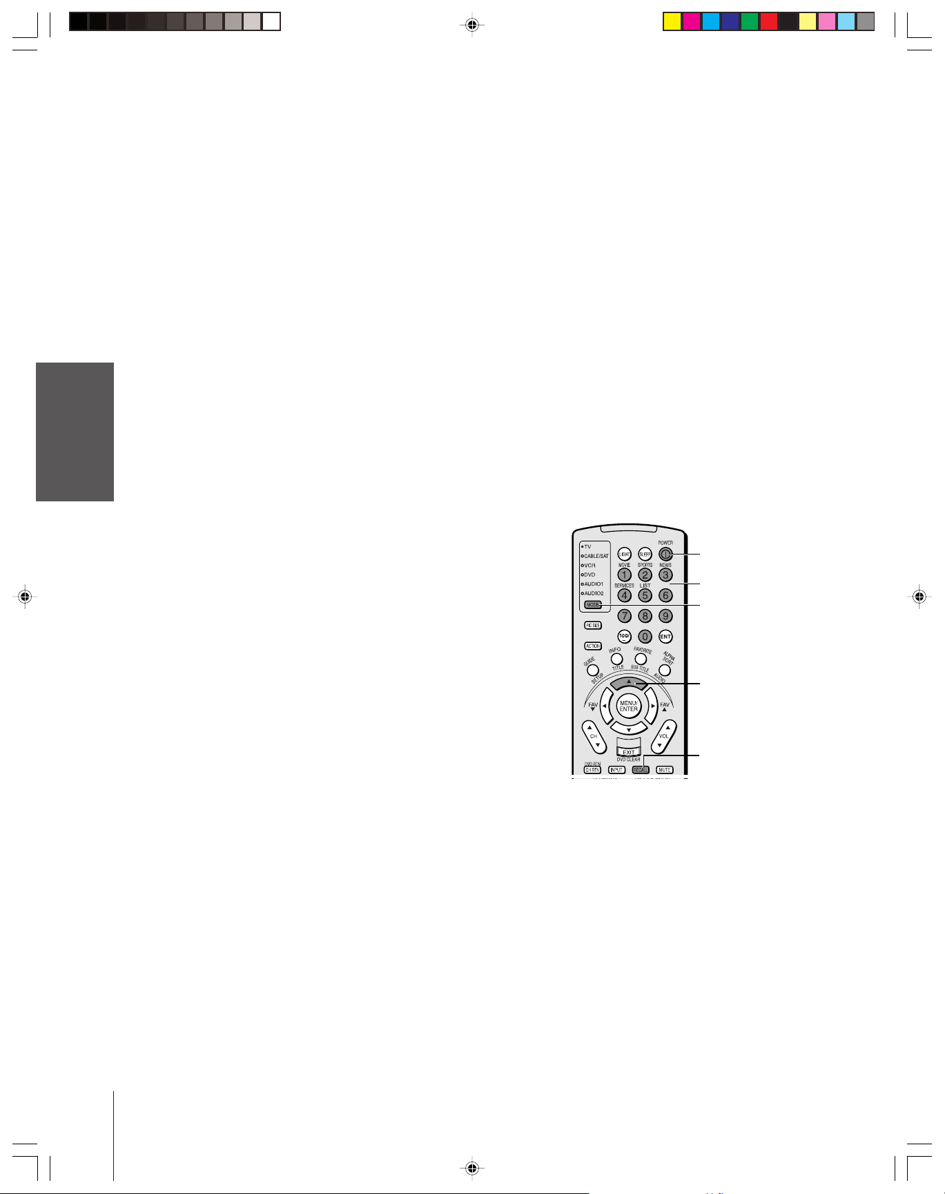
LCOS Projection Television
Introduction
Connecting
your TV
Remote Control
Using the
NOTE
Please read “Important notes about your
LCOS projection TV” on page 5.
S
U
N
M
O
C
E
A
C
I
R
E
M
A
A
B
I
H
S
O
T
I
S
O
1
4
0
0
R
P
R
O
D
U
C
T
S
,
I
N
C
.
5
4
6
9
A
.
1
o
N
F
E
I
L
Owner's Record
The model number and serial number are on the back
of your TV. Record these numbers in the spaces below.
Refer to these numbers whenever you communicate
with your Toshiba dealer about this TV.
Setting up
your TV
Using the TV’s
Features
Appendix
Index
57HLX82
57HLX82(E)01 10/29/02, 10:28 AM1
Model number: 57HLX82
Serial number:
23565770
Dear Customer,
Thank you for purchasing this Toshiba TV. This manual will help
you use the many exciting features of your new TV. Before
operating the TV, please read this manual completely,
and keep it nearby for future reference.
Child Safety
It Makes A Difference
Safety Precautions
WARNING: TO REDUCE THE RISK OF FIRE OR
ELECTRIC SHOCK, DO NOT EXPOSE THIS APPLIANCE
TO RAIN OR MOISTURE.
The lightning symbol in the triangle tells you that the
voltage inside this product may be strong enough to
cause an electric shock. DO NOT TRY TO SERVICE
The exclamation mark in the triangle tells you that
important operating and maintenance instructions
follow this symbol.
Lamp Unit Replacement
CAUTION: HOT SURFACE!
The temperature of the
lamp immediately after use
exceeds 392°F (200°C).
Touching the lamp at this temperature will result in
injury. ALLOW THE LAMP TO COOL FOR AT LEAST
ONE (1) HOUR BEFORE REPLACING IT.
The lamp in this product has a limited service life. The length
of service life varies depending on user settings. If you use the
lamp beyond its service life:
•
you may notice a reduction in the colors and/or brightness of
the picture, at which time you should replace the lamp unit; and
•
the strength of the quartz glass in the lamp will be reduced and
the lamp may rupture. If the lamp ruptures, the TV will not
operate until the lamp unit is replaced.
Note: The lamp unit is designed so broken lamp glass
remains securely inside the lamp unit.
See “Lamp unit replacement” on pages 59–62.
Note: The lamp unit contains mercury. Disposal of this material may be
regulated due to environmental considerations. For disposal or recycling
information, contact your local authorities or the Electronics Industries
Alliance (www.eiae.org).
WARNING: TO REDUCE THE RISK OF ELECTRIC
SHOCK, NEVER REMOVE TV COVERS, EXCEPT
AS SPECIFIED HEREIN. REFER ALL SERVICING
NOT SPECIFIED IN THIS MANUAL TO
QUALIFIED SERVICE PERSONNEL.
NOTE TO CATV INSTALLERS IN THE USA
This is a reminder to call the CATV system installer’s attention
to Article 820-40 of the NEC, which provides guidelines for proper
grounding and, in particular, specifies that the cable ground shall be
connected to the grounding system of the building, as close to the
point of cable entry as practical. For additional antenna grounding
information, see items 26 and 27 on page 4.
09/02 LCOS
2
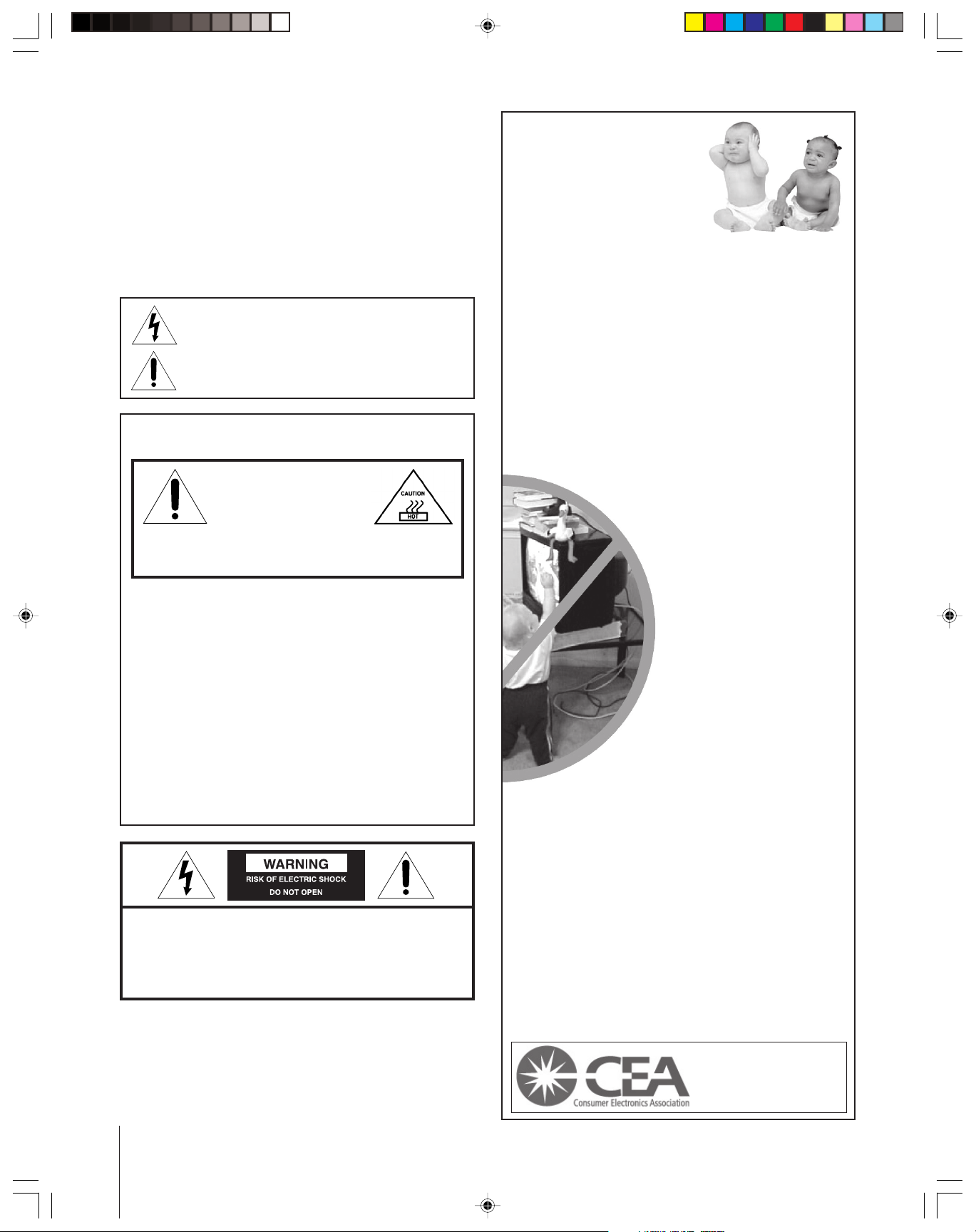
Where Your TV Stands
Congratulations on your purchase! As you enjoy
your new TV, keep these safety tips in mind:
The Issue
If you are like most Americans, you have a TV in your home.
Many homes, in fact, have more than one TV.
The home theater entertainment experience is a growing
trend, and larger TVs are popular purchases; however, they
are not always supported on the proper TV stands.
Sometimes TVs are improperly secured or inappropriately
situated on dressers, bookcases, shelves, desks, audio
speakers, chests, or carts. As a result, TVs may fall over,
causing unnecessary injury.
Toshiba Cares!
The consumer electronics industry
is committed to making home
entertainment enjoyable and safe.
The Consumer Electronics
Association formed the Home
Entertainment Support Safety
Committee, comprised of TV and
consumer electronics furniture
manufacturers, to advocate
children’s safety and educate
consumers and their families about
television safety.
Tune Into Safety
One size does NOT fit all! Use appropriate
furniture large enough to support the weight of your
TV (and other electronic components).
Use appropriate angle braces, straps, and anchors to secure
your furniture to the wall (but never screw anything directly
into the TV).
Carefully read and understand the other enclosed
instructions for proper use of this product.
Do not allow children to climb on or play with furniture
and TVs.
Avoid placing any item on top of your TV (such as a VCR,
remote control, or toy) that a curious child may reach for.
Remember that children can become excited while watching
a program and can potentially push or pull a TV over.
Share our safety message about this hidden hazard of
home with your family and friends. Thank you!
2500 Wilson Blvd.
Arlington, VA 22201 U.S.A.
Tel. 703-907-7600 Fax 703-907-7690
www.CE.org
CEA is the Sponsor, Producer and
Manager of the International CES
the
®
57HLX82(E)02-05 10/29/02, 10:28 AM2

Important Safety Instructions
1) Read these instructions.
2) Keep these instructions.
3) Heed all warnings.
4) Follow all instructions.
5) Do not use this apparatus near water.
6) Clean only with a dry cloth.
7) Do not block any ventilation openings. Install in
accordance with the manufacturer’s instructions.
8) Do not install near any heat sources such as radiators,
heat registers, stoves, or other apparatus (including
amplifiers) that produce heat.
9) Do not defeat the safety purpose of the polarized or
grounding type plug. A polarized plug has two blades
with one wider than the other. A grounding type plug has
two blades and a third grounding
prong. The wide blade or the third
prong are provided for your safety.
If the provided plug does not fit into
your outlet, consult an electrician
for replacement of the obsolete outlet.
CAUTION: To reduce the risk of electric shock, do not
use the polarized plug with an extension cord, receptacle,
or other outlet unless the blades can be inserted
completely to prevent blade exposure.
10) Protect the power cord from being
walked on or pinched, particularly at
plugs, convenience receptacles, and
the point where it exits the apparatus.
11) Only use attachments/accessories specified by the
manufacturer.
12) Use only with the cart, stand, tripod,
bracket, or table specified by the
manufacturer, or sold with the
apparatus. When a cart is used, use
caution when moving the cart/apparatus
combination to avoid injury from tip-over.
13) CAUTION: When moving this unit, push from the
sides. This unit has casters. Attempting to push the unit
from the front or rear may cause the unit to tip over.
14) Unplug this apparatus during lightning storms or
when unused for long periods of time.
15) Refer all servicing (except as specified on pages
59–64 in this manual) to qualified service personnel.
Servicing is required when the apparatus has been
damaged in any way, such as the power supply cord or
plug is damaged, liquid has been spilled or objects have
fallen into the apparatus, the apparatus has been exposed
to rain or moisture, does not operate normally, or has been
dropped.
16) WARNING: This product contains a lamp to project
the picture, and requires special safety precautions:
• See pages 59–64 for instructions on lamp unit
replacement and air filter care.
•DO NOT attempt to service this product except as
specified on pages 59–64. The only user-serviceable
items in this product are the lamp unit and air filter.
Wide plug
Installation, Care, and Service
Installation
Follow these recommendations and precautions and heed all
warnings when installing your TV:
17) Never modify this equipment. Changes or modifications
may void: a) the warranty, and b) the user’s authority to
operate this equipment under the rules of the Federal
Communications Commission.
18) DANGER: RISK OF SERIOUS PERSONAL
INJURY, DEATH, OR EQUIPMENT
DAMAGE! Never place the TV on
an unstable cart, stand, or table. The TV
may fall, causing serious personal injury,
death, or serious damage to the TV.
19) Never place or store the TV in direct sunlight; hot, humid
areas; areas subject to excessive dust or vibration;
or locations with temperatures at or below 41°F (5°C).
20) Always place the TV on the floor or a sturdy, level, stable
surface that can support the weight of the unit.
21) Never place items such as vases, aquariums, or candles
on top of the TV.
22) Never block or cover the slots or openings in the TV
cabinet back, bottom, and sides. Never place the TV:
• on a bed, sofa, rug, or similar surface;
• too close to drapes, curtains, or walls; or
• in a confined space such as a bookcase, built-in cabinet,
or any other place with poor ventilation.
The slots and openings are provided to protect the TV
from overheating and to help maintain reliable operation
of the TV.
23) Never allow anything to rest on or roll over the power
cord, and never place the TV where the power cord is
subject to wear or abuse.
24) Never overload wall outlets and extension cords.
25) Always operate this equipment from a 120 VAC, 60 Hz
power source only.
(continued on next page)
57HLX82(E)02-05 10/29/02, 10:28 AM3
09/02 LCOS
3
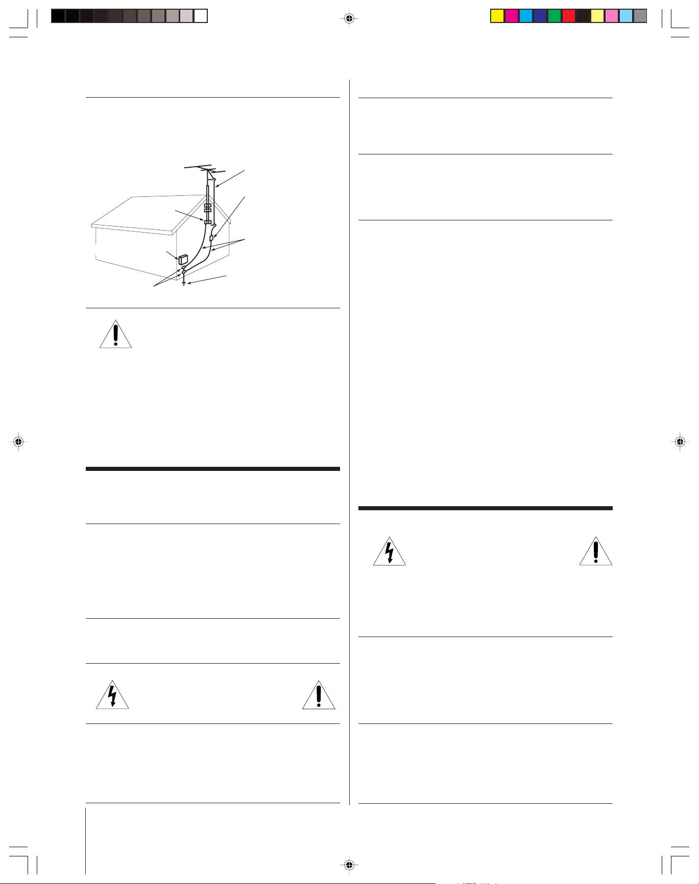
Ground clamp
Antenna discharge unit
(NEC Section 810-20)
Grounding conductors
(NEC Section 810-21)
Power service grounding
electrode system (NEC Art 250 Part H)
Ground clamps
Antenna lead-in wire
Electric service equipment
Installation (cont. from previous page) Care (cont. from previous column)
26) Always make sure the antenna system is properly
grounded to provide adequate protection against voltage
surges and built-up static charges (see Section 810 of the
National Electric Code).
27) DANGER: RISK OF SERIOUS PERSONAL
INJURY OR DEATH!
• Use extreme care to make sure you are never in
a position where your body (or any item you are in contact
with, such as a ladder or screwdriver) can accidentally
touch overhead power lines. Never locate the antenna
near overhead power lines or other electrical circuits.
• Never attempt to install any of the following during
lightning activity: a) an antenna system; or b) cables,
wires, or any home theater component connected to an
antenna or phone system.
Care
32) For added protection of your TV from lightning and power
surges, always unplug the power cord and disconnect the
antenna from the TV if you leave the TV unattended or
unused for long periods of time.
33) During normal use, the TV may make occasional snapping
or popping sounds. This is normal, especially when the
unit is being turned on or off. If these sounds become
frequent or continuous, unplug the power cord and
contact a Toshiba Authorized Service Center.
34) Special care for LCD (liquid crystal display) units:
• Lamp—
The lamp in this product has a limited service life.
The length of service life varies depending on user
settings. If you use the lamp beyond its service life:
– you may notice a reduction in the colors and/or
brightness of the picture, at which time you should
replace the lamp unit; and
– the strength of the quartz glass in the lamp will be
reduced and the lamp may rupture. If the lamp
ruptures, the TV will not operate until the lamp unit
is replaced.
See “Lamp unit replacement” on pages 59–62.
Note:
• The lamp unit is designed so broken lamp glass remains securely
inside the lamp unit.
• The lamp unit contains mercury, the disposal of which may be
regulated due to environmental considerations. For disposal or
recycling information, please contact your local authorities or
the Electronics Industries Alliance (www.eiae.org).
• Air Filter—This product contains an air filter that you
must clean a minimum of every two months. See “Air
filter care” on pages 63–64 for specific instructions.
57HLX82(E)02-05 10/29/02, 10:52 AM4
For better performance and safer operation of your TOSHIBA
TV, follow these recommendations and precautions:
28) Always sit approximately 10–25 feet away from the TV and
as directly in front of it as possible. The picture can appear
dull if you sit too far to the left or right of the TV, or if
sunlight or room lights reflect on the screen. Turn off the
TV to check for reflections on the screen, and then remove
the source of reflections while viewing the TV.
29) Always unplug the TV before cleaning. Never use liquid
or aerosol cleaners.
30) WARNING: RISK OF ELECTRIC SHOCK!
Never spill liquids or push objects of any
kind into the TV cabinet slots.
31) If the air temperature rises suddenly (for example, when
the TV is first delivered), condensation may form on the
lenses. This can make the picture appear distorted or the
color appear faded. If this happens, turn off the TV for
6to7 hours to allow the condensation to evaporate.
09/02 LCOS
4
Service
35) WARNING: RISK OF ELECTRIC SHOCK!
Never attempt to service the TV yourself,
except as specified on pages 59–64.
Opening and removing the covers may expose you to
dangerous voltage or other hazards. Failure to follow this
WARNING may result in death or serious injury.
Refer all servicing not specified in this manual to a Toshiba
Authorized Service Center.
36) If you have the TV serviced:
• Ask the service technician to use only replacement parts
specified by the manufacturer.
• Upon completion of service, ask the service technician
to perform routine safety checks to determine that the
TV is in safe operating condition.
37)When the TV reaches the end of its useful life, ask a
qualified service technician to properly dispose of the TV.
Note: The lamp unit contains mercury, the disposal of which may
be regulated due to environmental considerations. For disposal or
recycling information, please contact your local authorities or the
Electronics Industries Alliance (www.eiae.org).
Important notes about your LCOS projection TV
1) A spare lamp unit is included with this TV, and is stored in
the foam packing material on one side of the TV. Be sure to
retrieve the spare lamp unit before discarding the foam
packing material.
2) The light source for this TV is a projection lamp unit with
a limited service life. When the lamp wears out, the picture
may become dark or black, or the lamp may fail, at which
time you must replace the lamp unit. See “Lamp unit
replacement” on pages 59–62.
3) It may take up to 45 seconds to go from no picture to full
picture brightness each time you turn on the TV.
4) The image on this TV is created using LCOS (liquid crystal
on silicon) technology that is not susceptible to screen
“burn-in” from static images; therefore, this TV is ideal for
viewing programs with static video patterns, such as video
games or personal computer software. For details on
connecting your TV to a computer, see page 18.
Note: Interactive video games that involve shooting a “gun”
type of joystick at on-screen targets may not work on this TV.
5) The liquid crystal display on this TV is manufactured using
an extremely high level of precision technology; however, an
occasional pixel (dot of light) may display constantly on the
screen. This is a structural property of LCOS technology and
is not a sign of malfunction. Such pixels are not visible when
the picture is viewed from a normal viewing distance (see
item 28 on page 4).
6) The green and red LED lights on the control touchpad (on
the lower right corner of the TV screen) indicate your TV’s
current status. If either light flashes, see “LED indications”
on page 64 for details.
7) A 720p signal will not display in its native format on this
TV, but will be upconverted to a 1080p signal.
8) This TV contains several cooling fans to moderate the
internal temperature. The air intake for these fans is
through an air filter that you must clean a minimum
of every two (2) months. To maintain maximum cooling
efficiency of the fans, clean the air filter regularly and
never place the back of the TV where the air filter will be
blocked (against a curtain, for example). See “Air filter
care” on pages 63–64.
9) The screen on this TV is manufactured from
tempered glass. To prevent damage, never
strike the glass with a sharp or heavy object.
10) Review all safety and operating information in this owner’s
manual before you use your TV.
FCC compliance information
Federal Communications Commission (FCC)
This equipment complies with Part 15 of the FCC rules.
FCC Declaration of Conformity Compliance Statement
(Part 15)
The Toshiba 57HLX82 LCOS Projection Television complies
with Part 15 of the FCC rules. Operation is subject to the
following two conditions: (1) this device may not cause
harmful interference, and (2) this device must accept any
interference that may cause undesired operation.
The party responsible for compliance to these rules is:
Toshiba America Consumer Products, Inc.
82 Totowa Rd.
Wayne, NJ 07470
Ph: (888) 867-4377
NOTE: This equipment has been tested and found to comply
with the limits for a Class B digital device, pursuant to Part 15
of the FCC rules. These limits are designed to provide
reasonable protection against harmful interference in a
residential installation. This equipment generates, uses,
and can radiate radio frequency energy and, if not installed
and used in accordance with the instructions, may cause
harmful interference to radio communications. However,
there is no guarantee that interference will not occur in a
particular installation. If this equipment does cause harmful
interference to radio or television reception, which can be
determined by removing and applying power to the
equipment, the user is encouraged to try to correct the
interference by one or more of the following measures:
• Reorient or relocate the receiving antenna.
• Increase the separation between the equipment and the
receiver.
• Connect the equipment into an outlet on a circuit different
from that to which the receiver is connected.
• Consult the dealer or an experienced radio/TV technician
for help.
Changes or modifications to this equipment not expressly
approved by Toshiba could void the user’s authority to
operate this equipment.
57HLX82(E)02-05 10/29/02, 10:28 AM5
09/02 LCOS
5
Important safety information.............................. 2–4
Important notes about your LCOS projection TV ............. 5
FCC compliance information ............................................ 5
Introduction................................................................ 7
Welcome to Toshiba ........................................................... 7
Exploring your new TV...................................................... 7
Note regarding Quick Connect Guide ............................. 7
Connecting your TV .................................................. 8
Note regarding picture quality............................................ 8
Connecting a VCR............................................................. 9
Connecting a cable converter box ....................................... 9
Connecting a cable converter box and VCR ..................... 10
Connecting a DVD player or satellite receiver and
a VCR .............................................................................. 11
Connecting a DVD player with ColorStream
®
(component video) and a VCR......................................... 12
Connecting a DTV receiver/set-top box with
ColorStream
®
(component video) and a VCR .................. 13
Connecting a DVD player or DTV receiver/
set-top box with digital audio (coaxial or optical) ............. 14
Connecting two VCRs ..................................................... 14
Connecting a camcorder .................................................. 15
Connecting a device to the DVI/HDCP input ................. 15
Connecting a device to the IR blaster ............................... 16
Connecting an audio system ............................................ 17
Connecting an A/V receiver ............................................. 17
Connecting a computer .................................................... 18
Using the remote control ...................................... 19
Preparing the remote control for use ................................ 19
Installing the remote control batteries .............................. 19
Remote Control functional key chart ........................ 20
Programming the remote control for use with
your audio/video devices .................................................. 22
Device code setup ...................................................... 22
Searching and sampling the code of a device (8500) ... 22
Using the volume lock feature (8000) ........................ 23
Operational feature reset (8900) ................................ 23
Device code table....................................................... 24
VCR setup codes .................................................. 24
Cable box setup codes .......................................... 24
CD Player setup codes ......................................... 25
Receiver setup codes ............................................. 25
Cassette Player setup codes ................................... 25
Laser Disc setup codes .......................................... 25
DVD setup codes ................................................. 25
Satellite Receiver setup codes ................................ 25
Learning about the remote control ................................... 26
Setting up your TV .................................................. 27
Learning about the menu system ...................................... 27
Using the Quick Connect Guide...................................... 28
Changing the on-screen display language ......................... 29
Selecting the antenna input .............................................. 29
Adding channels to the TV’s memory .............................. 30
Programming channels automatically ........................ 30
Adding and erasing channels manually ...................... 31
Changing channels ........................................................... 31
Changing channels using SpeedSurf .......................... 31
Using the TV’s features.......................................... 32
Adjusting the channel settings .......................................... 32
Switching between two channels using Channel
Return .................................................................... 32
Switching between two channels using SurfLock
Programming your favorite channels ......................... 32
Labeling channels ...................................................... 33
™
..... 32
Viewing the wide-screen picture formats .......................... 35
Selecting the picture size ............................................ 35
Scrolling the Theater Wide picture
(Theater Wide 2 and 3 only) ..................................... 37
Selecting the cinema mode ........................................ 37
Using the POP double-window feature ............................ 38
Switching the main and POP pictures ....................... 39
Freezing the POP picture ........................................... 39
Using the favorite channel search function ................ 39
Using the LOCKS menu .................................................. 40
Entering the PIN code............................................... 40
If you cannot remember your PIN code .................... 40
Using the V-CHIP menu ................................................. 41
ENABLE BLOCKING ............................................. 41
TV RATING (Independent rating system for
broadcasters) .............................................................. 41
MPAA RATING (Independent rating system for
movies) ...................................................................... 42
BLOCKING OPTION ............................................ 42
Unlocking programs temporarily ............................... 43
Locking channels ............................................................. 43
Locking video inputs ........................................................44
Using the front panel lock feature .................................... 45
Changing the PIN code ................................................... 45
Adjusting the picture ........................................................ 46
Selecting the picture mode......................................... 46
Adjusting the picture quality ..................................... 46
Saving your new preferences ...................................... 47
Using CableClear
™
DNR (digital noise reduction) .... 47
Selecting the color temperature.................................. 47
Resetting your picture quality adjustments ................ 48
Picture menu adjustments for PC IN mode ............... 48
Selecting the video input source ....................................... 49
Labeling the video input sources ...................................... 49
Using the closed caption feature ....................................... 50
Setting the sleep timer ...................................................... 51
Setting the clock ............................................................... 51
Adjusting the sound ......................................................... 52
Muting the sound ...................................................... 52
Selecting stereo/SAP broadcasts ................................. 52
Enjoying the Dolby Virtual TruSurround sound
feature ................................................................... 53
Enjoying the WOW
™
surround sound features ......... 53
Adjusting the sound quality ....................................... 54
Resetting your audio adjustments .............................. 54
Using the sub-bass system (SBS) ................................ 55
Turning off the built-in speakers ................................ 55
Selecting the Audio OUT sound ............................... 56
Using the StableSound
®
feature ................................. 56
Assigning the corresponding video input for the optical
and coaxial DIGITAL AUDIO IN terminals ................ 57
Displaying on-screen information .................................... 57
Viewing the demonstration mode .................................... 58
Understanding the auto power off feature ........................ 58
Understanding the last mode memory feature .................. 58
Appendix ................................................................... 59
Lamp unit replacement .................................................... 59
When to replace the lamp unit .................................. 59
How to replace the lamp unit .................................... 60
Lamp unit disposal .................................................... 62
Air filter care .................................................................... 63
How to clean the air filter .......................................... 63
LED indications ............................................................... 64
Specifications ................................................................... 65
Tr oubleshooting ............................................................... 66
Limited United States Warranty ....................................... 67
Limited Canada Warranty ................................................ 68
Index .......................................................................... 71
6
57HLX82(E)06 10/29/02, 10:28 AM6
Introduction
MENU
VOLUME
CHANNEL
EXIT
TV/VIDEO
POWER
Introduction
Welcome to Toshiba
Congratulations! You have purchased one of the finest LCOS (liquid
crystal on silicon) projection TVs on the market. The goal of this manual
is to guide you through setting up and operating your Toshiba TV as
quickly as possible. This manual is for model 57HLX82. The model and
serial numbers are on the back of your TV. Write these numbers in the
space provided on the front cover of this manual for your records.
Instructions in this manual are based on using the remote control. You
also can use the controls on the TV touchpad if they have the same name
as those referred to on the remote control. Please read all safety and
operating instructions carefully, and keep this manual for future
reference.
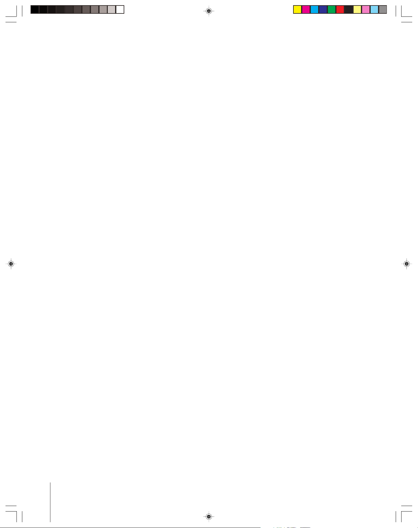
Exploring your new TV
You can operate your TV using the control touchpad on the TV front or
the remote control. The A/V terminals for connecting other equipment
to your TV are on the back panel and inside the storage compartment
(see illustrations below). Also see “Connecting your TV” on pages 8–18.
TV front
MENU VOLUME CHANNEL EXITTV/VIDEO POWER
Control touchpad on TV front (
Volume
x •
MENU VOLUME CHANNEL EXIT TV/VIDEO POWER
Gently touch the printed keys.
Channel
zy
See “Important notes about
your LCOS projection TV” on
page 5.
Note Regarding
Quick Connect Guide
The Quick Connect Guide
automatically appears on-screen
the first time the TV is turned on.
This feature provides on-screen
instructions to guide you through
the initial setup of your TV.
To stop the Quick Connect Guide,
either press EXIT or turn off the TV.
See page 28 for details.
Remote control
)
Connecting
your TV
Remote Control
Using the
Setting up
your TV
Remote control sensor
(behind the screen)
TV front with storage door open
Lift bottom of door to open.
(
MENU
)
VOLUME
CHANNEL
EXIT
TV/VIDEO
POWER
Storage compartment
for A/V equipment
TV back
S-VIDEO
VIDEO
L/
MONO
AUDIO
VIDEO 1INVIDEO 2INColorstream
MENU
*
Green ON = Touchpad key being pressed;
x •zy
Red ON = Power ON.
See page 64 for additional LED indications.
VIDEO-3 A/V terminals
(inside storage compartment)
AUDIO
VIDEO-3 IN
VIDEOS-VIDEO L/MONO R
R
VIDEO 1 VIDEO 2
IN
{
ANT-1
L
AUDIO
R
COLOR
STREAM HD-1
{
HD -1 IN
ANT
IN
{
ANT( 75
ANT-1 OUT ANT-2
Y
P
B
P
R
IN OUT
{
ANT-2
OUT
{
{
)
L
AUDIO
R
COLOR
STREAM HD-2
{
Colorstream
HD- 2 IN
IN
Y
P
B
P
R
VIDEO
L/
MONO
AUDIO
R
OUT
A/V
TV/VIDEO
EXIT
AUDIO CENTER
L
R
VAR
AUDIO
{
{
Variable
Audio
OUT
Green and Red
LED indicators*
CHANNEL IN
{
AUDIO CENTER
CHANNEL IN
L
L
ON OFF
R
IN
{
DVI/
HDCP
AUDIO
IN
R
For PC
{
PC
AUDIO
IN
CHANNEL
For
DVI / HDCP
POWER
DIGITAL AUDIO IN
(COAXIAL / OPTICAL)
{
DIGITAL
AUDIO IN
COAXIAL OPTICAL
{
AUDIO
CENTER
ON/OFF
IR BLASTER
IN / OUT
{
IR BLASTER
IN
PC IN DVI / HDCP IN
{
PC VIDEO
IN
(Analog RGB
D-sub 15-pin)
DVI/HDCP VIDEO
(Digital single-link)
Using the TV’s
Features
Appendix
OUT
Index
{
IN
7
57HLX82(E)07 10/29/02, 10:28 AM7
Connecting your TV
Note: One IR blaster cable is provided with your TV. No other cables are
Introduction
your TV
Connecting
Using the
Remote Control
provided.
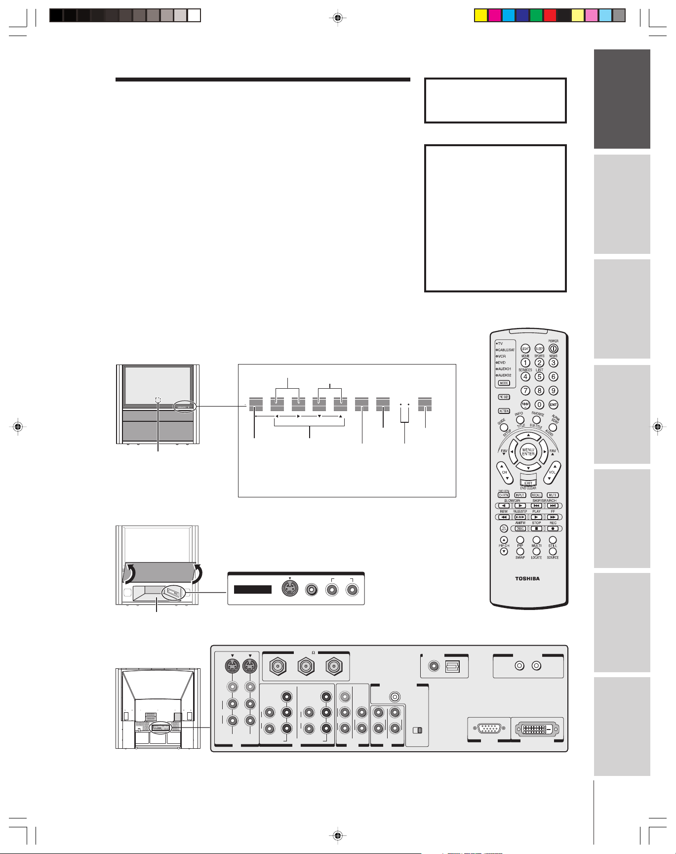
Coaxial cable is the type of cable connected to your antenna, cable TV
service, or cable converter box. Coaxial cable has “F” connectors.
Standard stereo A/V cables usually come in sets of three, and are
typically color-coded according to use: yellow for video, red for stereo
right audio, and white for stereo left (or mono) audio. Your TV’s standard
A/V inputs are color-coded in the same manner as the cables.
S-video cable is for use with video equipment that has an S-Video
connector.
Component video cables come in sets of three (typically color-coded
red, green, and blue), and are for use with video equipment that has
®
component video connectors. Your TV’s ColorStream
(component video)
inputs are color-coded in the same manner as the cables.
Digital audio cable is for use with video equipment that has digital
audio output (e.g., a DVD player or game console). You can use either
Optical
optical or coaxial digital audio input (see pages 14, 53, and 57).
DVI-D digital single-link cable is for use with video equipment that has
Coaxial
a DVI-D digital single-link connector (see page 15).
PC video cable (D-sub 15-pin) is for use with a computer that has a
D-sub 15-pin connector (see page 18).
IR blaster cable is used to remotely control other A/V equipment
(equipped with an an infrared sensor) through the TV (see page 16).
Coaxial (antenna) cable
Standard stereo A/V cables
(typically color-coded yellow for video,
red and white for audio)
S-video cable
Component video cables
(typically color-coded red, green, blue)
Digital audio cable
your TV
Setting up
Features
Using the TV’s
Appendix
NOTE REGARDING PICTURE QUALITY
When connecting video equipment to your Toshiba TV:
For GOOD picture quality: Use a standard stereo A/V (yellow)
video cable.
For BETTER picture quality: If your equipment has an S-video
connector, use an S-video cable instead of a standard yellow video cable.
(You still must connect the standard red and white audio cables for full
system connection, but do not connect a standard yellow video cable at
the same time or the picture performance will be unacceptable.)
For BEST picture quality: If your equipment has component video
connectors, use component video cables instead of a standard yellow
video cable or an S-video cable (plus the standard red and white audio
cables for full system connection.) If your equipment has a DVI-D
digital single-link connector, use a DVI-D cable (plus standard red
and white audio cables connected to the audio terminals labeled
“For DVI/HDCP IN” for full system connection).
DVI-D digital single-link cable
PC video cable (D-sub 15-pin)
IR blaster cable
CAUTION:
Do not plug in any power cords until you have
finished connecting all equipment.
Index
8
57HLX82(E)08-18 10/29/02, 10:28 AM8
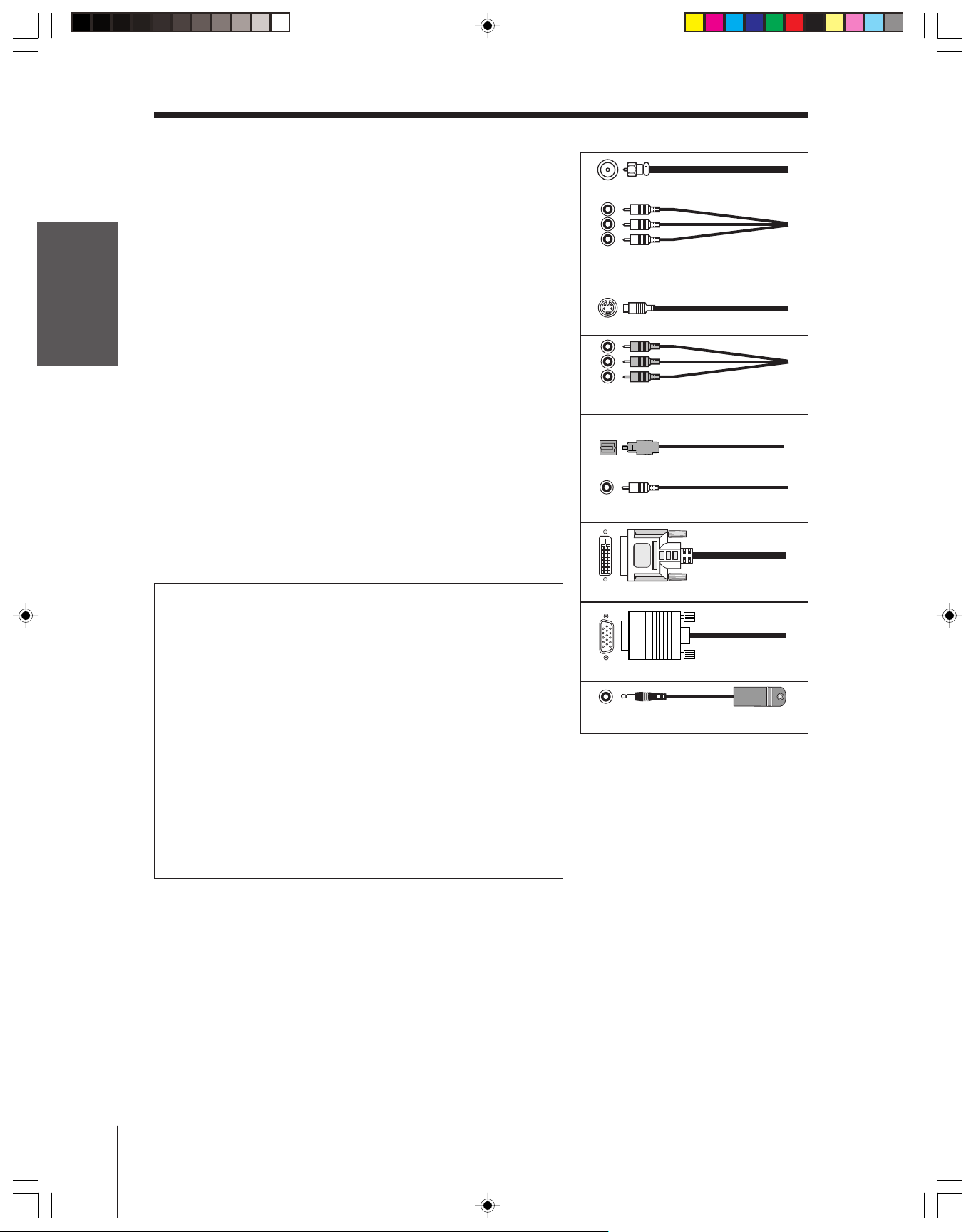
Connecting a VCR
Introduction
This connection allows you to watch local channels and video
programs, watch video tapes, and record one channel while watching
another channel.
You will need:
• two coaxial cables
• one set of standard A/V cables
From Cable Box or Antenna
Stereo VCR
VIDEO AUDIO
LR
S-VIDEO
VIDEO
L/
MONO
AUDIO
R
VIDEO 1 VIDEO 2
TV
IN
OUT
ANT-1 OUT ANT-2
L
AUDIO
R
COLOR
STREAM HD-1
IN
OUT to TV
)
ANT( 75
Y
PB
L
AUDIO
PR
R
COLOR
STREAM HD-2
IN OUT
Y
PB
PR
VIDEO
L/
MONO
AUDIO
R
IN from ANT
CH 3
CH 4
L
R
VAR
AUDIO
Note:
If you have a mono VCR, connect L/Mono to
VCR Audio OUT using only one audio cable.
If you have an S-VHS VCR, use an S-video
cable instead of the standard video cable.
Do not connect a standard video cable and
an S-video cable to VIDEO 1 (or VIDEO 2) at
the same time or the picture performance will
be unacceptable.
The unauthorized recording, use, distribution,
or revision of television programs, videotapes,
DVDs, and other materials is prohibited under
the Copyright Laws of the United States and
other countries, and may subject you to civil
and criminal liability.
Connecting
your TV
Remote Control
Using the
Setting up
your TV
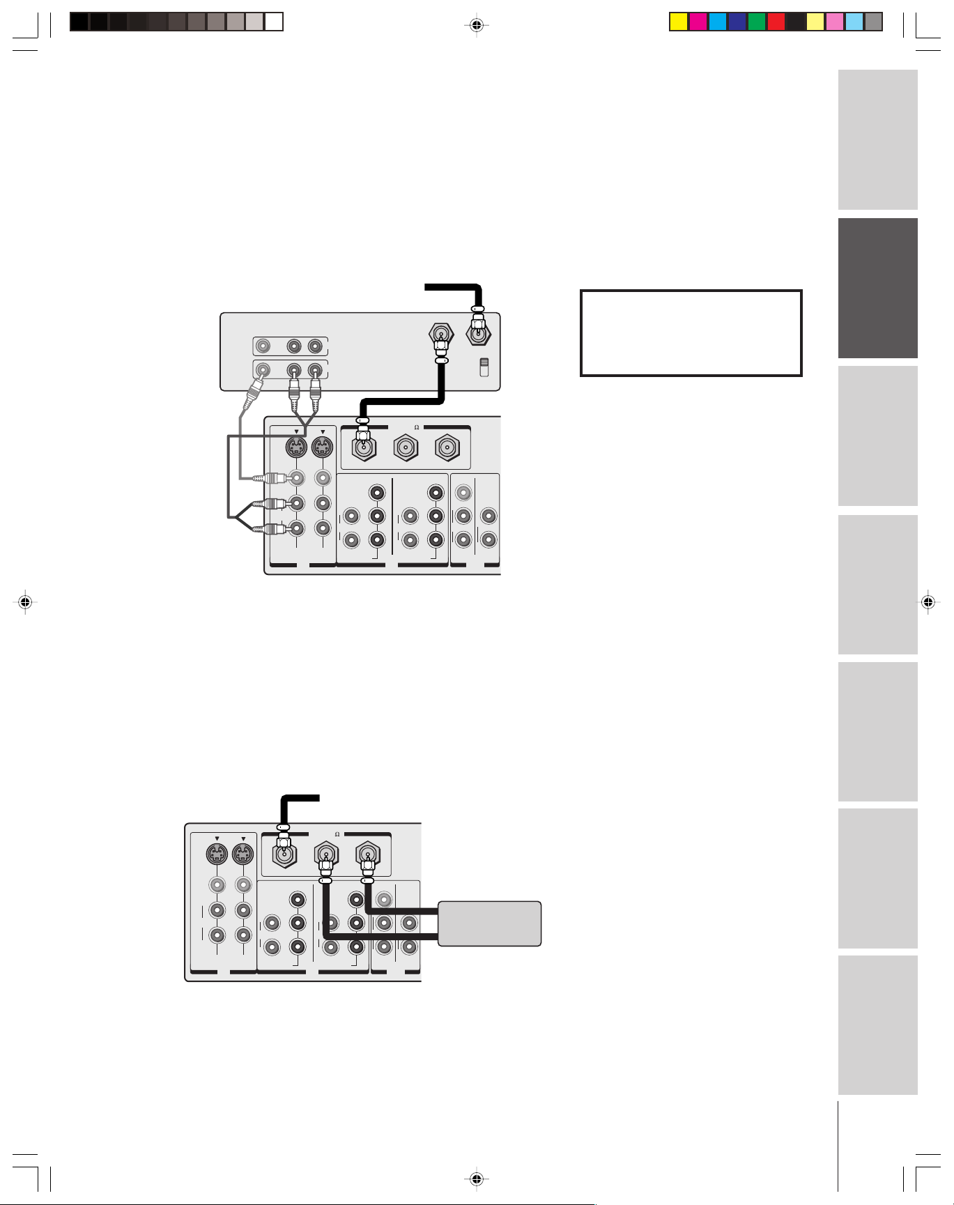
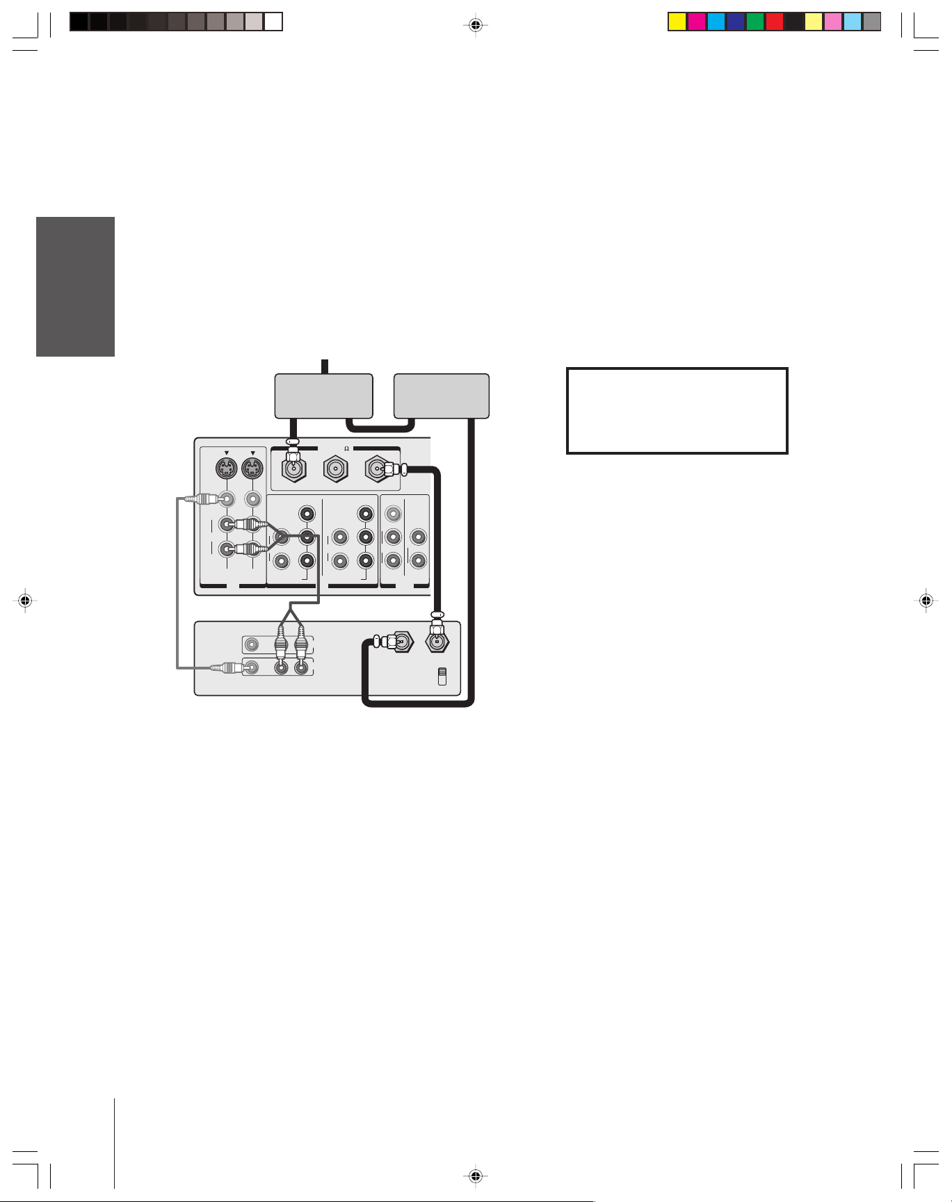
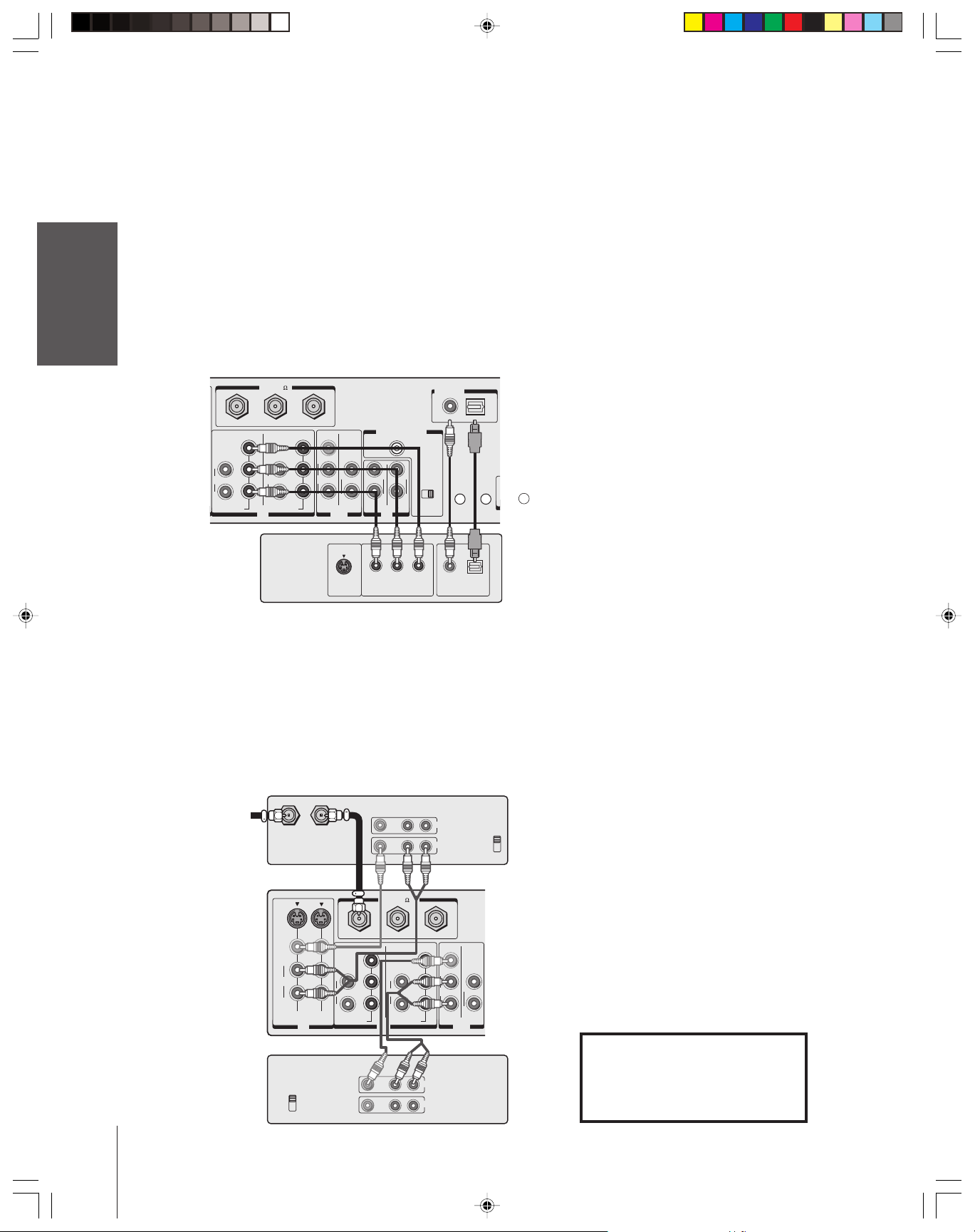
Connecting a cable converter box
This connection allows you to watch basic and premium cable
channels.
To use the TV’s features, select ANT-1. To view premium channels,
select ANT-2, tune the TV to channel 3 or 4 (whichever channel is
vacant in your area), and use the converter box to change channels.
You will need:
• three coaxial cables
From Cable
TV
)
S-VIDEO
VIDEO
L/
MONO
AUDIO
R
VIDEO 1 VIDEO 2
L
AUDIO
R
COLOR
STREAM HD-1
IN
ANT( 75
ANT-1 OUT ANT-2
Y
P
B
L
AUDIO
P
R
R
COLOR
STREAM HD-2
IN OUT
Y
P
B
P
R
VIDEO
L/
MONO
AUDIO
R
L
R
VAR
AUDIO
OUT
Cable converter box
IN
Note:
When you use a converter box with your TV,
the remote control will not operate some
features, such as programming your favorite
channels, labeling channels, and locking
channels.
Using the TV’s
Features
Appendix
Index
57HLX82(E)08-18 10/29/02, 10:28 AM9
9
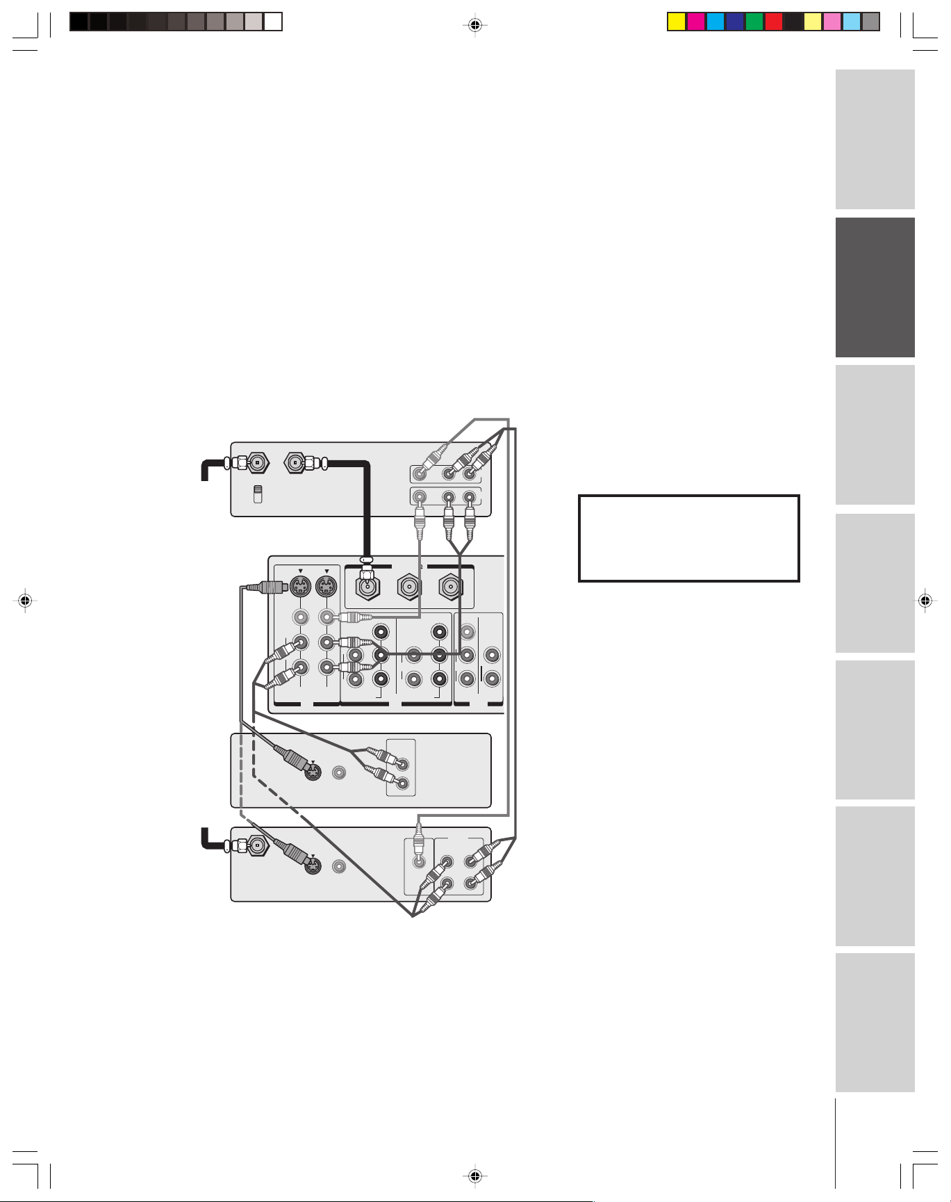
Connecting a cable converter box and VCR
This connection allows you to watch and record basic and premium
cable channels, watch videotapes, and record one channel while
Introduction
watching another channel. To use the TV’s features, select ANT-1.
To view premium channels or record with the VCR, select ANT-2,
tune the TV and VCR to channel 3 or 4 (whichever channel is vacant
in your area), and use the converter box to change channels.
You will need:
your TV
Connecting
Using the
Remote Control
your TV
Setting up
• one cable signal splitter
• five coaxial cables
• one set of standard A/V cables
From Cable
IN
Cable signal splitter
OUT
TV
S-VIDEO
VIDEO
L/
MONO
AUDIO
R
VIDEO 1 VIDEO 2
IN
Stereo VCR
VIDEO
L
AUDIO
R
COLOR
STREAM HD-1
LR
LR
ANT( 75
ANT-1 OUT ANT-2
Y
P
B
L
AUDIO
P
R
R
COLOR
STREAM HD-2
IN OUT
IN
OUT
AUDIO
OUT
Note:
If you have a mono VCR, connect L/Mono to
VCR Audio OUT using only one audio cable.
If you have an S-VHS VCR, use an S-video
cable instead of a standard video cable. Do
not connect a standard video cable and an
S-video cable to VIDEO 1 (or VIDEO 2) at
the same time or the picture performance will
be unacceptable.
When you use a converter box with your TV,
the remote control will not operate some
features, such as programming your favorite
channels, labeling channels, and locking
channels.
The unauthorized recording, use, distribution,
Cable converter box
OUTIN
)
VIDEO
Y
L/
MONO
P
B
L
AUDIO
P
R
R
R
VAR
AUDIO
IN from ANT
OUT to TV
CH 3
CH 4
or revision of television programs, videotapes,
DVDs, and other materials is prohibited under
the Copyright Laws of the United States and
other countries, and may subject you to civil
and criminal liability.
Features
Using the TV’s
Appendix
Index
10
57HLX82(E)08-18 10/29/02, 10:28 AM10
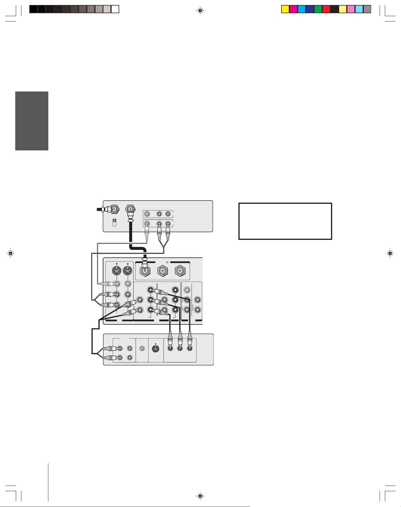
Connecting a DVD player or satellite receiver
and a VCR
Introduction
This connection allows you to watch DVD/satellite, VCR, and TV
programs, and record one channel while watching another channel.
You will need:
• two (or three, if satellite receiver is used) coaxial cables
• one set of standard A/V cables (between the TV and VCR)
(plus one additional set of standard A/V cables if satellite receiver
is used)
• one S-video cable (between the TV and DVD player/satellite
receiver)
• one pair of standard audio cables (between the TV and DVD
player/satellite receiver) (or one digital audio cable, if applicable;
see pages 14, 53, and 57 for details on digital audio connection)
Stereo VCR
From
Antenna
IN from ANT
CH 3
CH 4
TV
S-VIDEO
OUT to TV
VIDEO AUDIO
)
ANT( 75
L
R
IN
OUT
Note:
For the highest possible picture quality from a
DVD player/satellite receiver without
component video or DVI/HDCP, use an
S-video cable between the TV and DVD
player/satellite receiver. (If your DVD player/
satellite receiver is compatible with
component video, see page 12. If your DVD
player/satellite receiver is compatible with
DVI/HDCP, see page 15).
Do not connect both an S-video cable and
astandard video cable between the TV
and DVD player/satellite receiver at the
same time, or the picture performance will
be unacceptable.
Do not connect the DVD player/satellite
receiver and VCR to the same video channel
on the TV. (See the illustrations, which show
the DVD player/satellite receiver connected to
VIDEO1 on the TV and the VCR connected
to VIDEO 2 on the TV.)
The unauthorized recording, use, distribution,
or revision of television programs, videotapes,
DVDs, and other materials is prohibited under
the Copyright Laws of the United States and
other countries, and may subject you to civil
and criminal liability.
Connecting
your TV
Remote Control
Using the
Setting up
your TV
From
Satellite
Dish
IN from ANT
VIDEO
L/
MONO
AUDIO
R
VIDEO 1 VIDEO 2
IN
S-VIDEO
S-VIDEO
ANT-1 OUT ANT-2
Y
P
L
AUDIO
R
COLOR
STREAM HD-1
B
P
R
IN OUT
DVD player
AUDIO
OUT
L
VIDEO
OUTOUT
R
Satellite receiver
VIDEO
OUTOUT
L
AUDIO
R
COLOR
STREAM HD-2
VIDEO
OUT
VIDEO
Y
L/
MONO
P
B
AUDIO
P
R
R
AUDIO
OUT
LRL
L
R
VAR
AUDIO
Using the TV’s
Features
Appendix
R
Index
57HLX82(E)08-18 10/29/02, 10:28 AM11
11
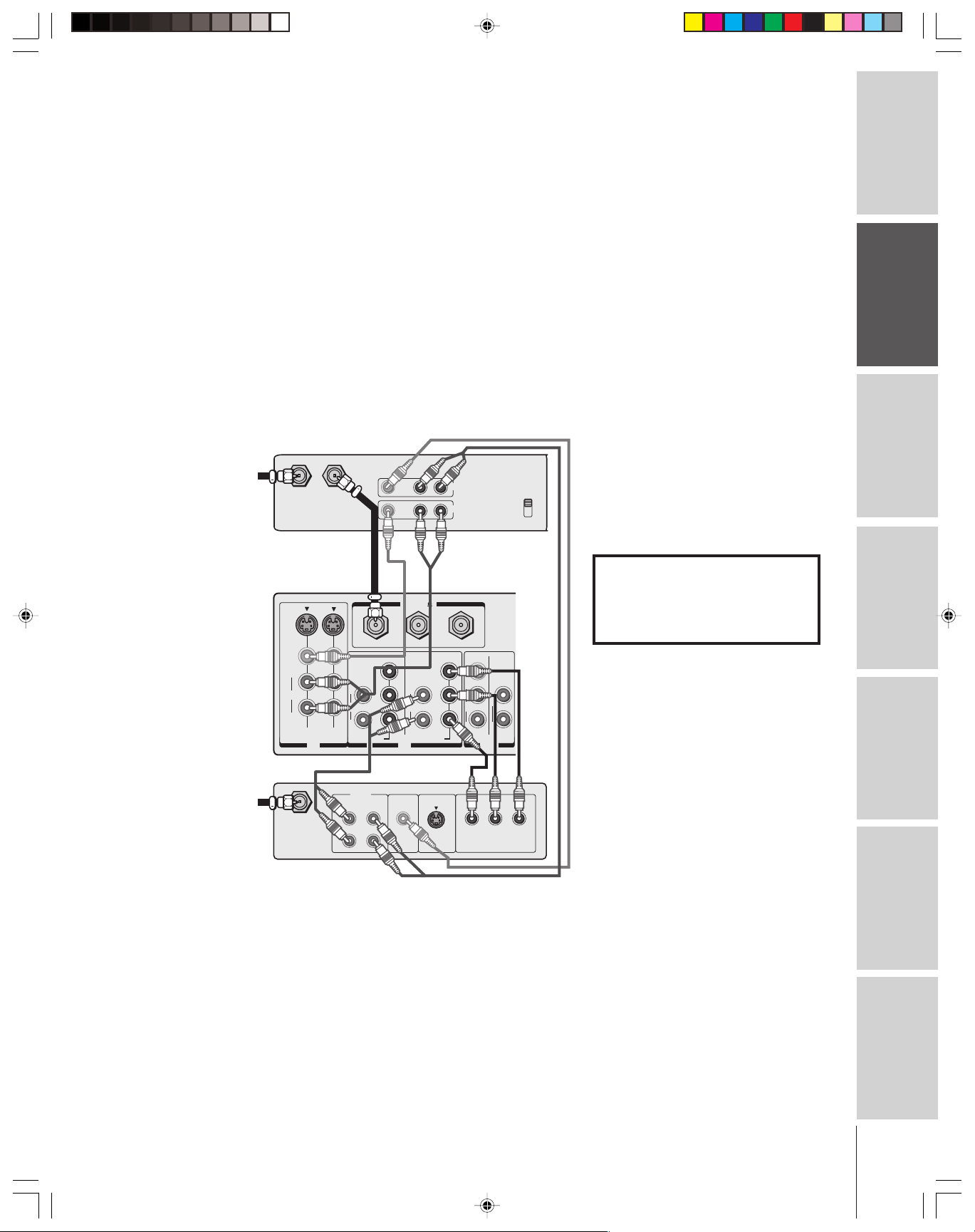
Connecting a DVD player with ColorStream
(component video) and a VCR
This connection allows you to watch DVD, VCR, and TV programs,
Introduction
your TV
Connecting
Using the
Remote Control
and record TV programs. You can record one channel while watching
another channel.
Your TV has ColorStream
your TV to a DVD player with component video (such as a Toshiba
DVD player with ColorStream
and realism.
You will need:
From Antenna
®
®
(component video) inputs. Connecting
®
) can greatly enhance picture quality
• two coaxial cables
• one set of standard A/V cables
• one set of component video cables
• one pair of standard audio cables (or one digital audio cable, if
applicable; see pages 14, 53, and 57 for details on digital audio
connection)
Stereo VCR
IN from ANT
CH 3
CH 4
OUT to TV
VIDEO AUDIO
LR
IN
OUT
Note:
For the highest possible picture quality, use
component video cables (or a DVI-D digital
single-link cable) between the TV and DVD
player.
You can connect component video cables
from the DVD player to either set of
ColorStream terminals on the TV (HD1 or
HD2).
The ColorStream HD1 and HD2 terminals
can be used with Progressive (480p, 720p)
and Interlaced (480i, 1080i) scan systems.
If your DVD player is not compatible with
component video (or DVI/HDCP), use an
S-video cable (plus an audio connection)
instead.
Do not connect both S-Video and standard
video cables between the TV and DVD player
at the same time, or the picture performance
will be unacceptable.
The unauthorized recording, use, distribution,
or revision of television programs, videotapes,
DVDs, and other materials is prohibited under
the Copyright Laws of the United States and
other countries, and may subject you to civil
and criminal liability.
your TV
Setting up
Features
Using the TV’s
Appendix
)
S-VIDEO
VIDEO
L/
MONO
AUDIO
R
VIDEO 1 VIDEO 2
R
IN
AUDIO
L
OUT
L
R
L
AUDIO
R
COLOR
STREAM HD-1
VIDEO
OUT
ANT( 75
ANT-1 OUT ANT-2
Y
P
B
L
AUDIO
P
R
R
COLOR
STREAM HD-2
IN OUT
RPB
P
S-VIDEO
COMPONENT VIDEO
DVD player with component video
TV
VIDEO
Y
L/
MONO
P
B
L
AUDIO
P
R
R
R
VAR
AUDIO
Y
Index
12
57HLX82(E)08-18 10/29/02, 10:28 AM12
Introduction
Connecting a DTV receiver/set-top box with
®
ColorStream
This connection allows you to watch DTV (digital TV broadcast),
VCR, and TV programs, and record DTV and TV programs. You can
record from one source while watching a program from another
source.
Your TV has ColorStream
your TV to a DTV receiver with component video can greatly
enhance picture quality and realism.
You will need:
• three coaxial cables
• two sets of standard A/V cables
• one set of component video cables
• one pair of standard audio cables (or one digital audio cable, if
applicable; see pages 14, 53, and 57 for details on digital audio
connection)
From
Antenna
(component video) and a VCR
®
(component video) inputs. Connecting
Stereo VCR
VIDEO AUDIO
LR
)
L
AUDIO
R
COLOR
STREAM HD-2
OUT
IN
CH 3
CH 4
VIDEO
Y
L/
MONO
P
B
L
AUDIO
P
R
R
R
VAR
AUDIO
IN from ANT OUT to TV
TV
S-VIDEO
VIDEO
L/
MONO
AUDIO
R
VIDEO 1 VIDEO 2
IN
ANT( 75
ANT-1 OUT ANT-2
Y
P
L
AUDIO
R
COLOR
STREAM HD-1
B
P
R
IN OUT
Note:
For the highest possible picture quality, use
component video cables (or a DVI-D digital
single-link cable) between the TV and DTV
receiver.
You can connect component video cables
from the DTV receiver to either set of
ColorStream terminals on the TV (HD1 or
HD2).
The ColorStream HD1 and HD2 terminals
can be used with Progressive (480p, 720p)
and Interlaced (480i, 1080i) scan systems.
If your DTV receiver is not compatible
with component video (or DVI/HDCP), use
an S-video cable (plus an audio connection)
instead.
Do not connect both S-Video and standard
video cables between the TV and DTV
receiver at the same time, or the picture
performance will be unacceptable.
To record from the DTV receiver, set the VCR
to Line IN. To monitor recording from the DTV
receiver, set the VCR to Line IN and the TV to
VIDEO 1.
The unauthorized recording, use, distribution,
or revision of television programs, videotapes,
DVDs, and other materials is prohibited under
the Copyright Laws of the United States and
other countries, and may subject you to civil
and criminal liability.
Connecting
your TV
Remote Control
Using the
Setting up
your TV
Using the TV’s
Features
From
DTV Antenna
57HLX82(E)08-18 10/29/02, 10:28 AM13
AUDIO
OUT
L
Satelite IN
L
R
R
VIDEO
OUT
S-VIDEO
DTV receiver with component video
P
RPB
COMPONENT VIDEO
Y
Appendix
Index
13
Connecting a DVD player or DTV receiver/
set-top box with digital audio (coaxial or optical)
This connection allows you to hear Dolby® Virtual TruSurround
Introduction
your TV
Connecting
Using the
Remote Control
sound (virtual 5.1-channel surround sound) from the TV speakers
(also see page 53). You can connect a DVD player or DTV receiver/
set-top box with digital audio output to either the coaxial or optical
DIGITAL AUDIO IN terminal on the TV.
You can use any video input except ANT-1 and ANT-2 in
conjunction with either digital audio input. See “Assigning the
corresponding video input for the optical and coaxial DIGITAL
AUDIO IN terminals” on page 57.
You will need:
• one set of component video cables (in this example)
• one digital audio cable (coaxial or optical)
TV
L
AUDIO
R
COLOR
STREAM HD-1
ANT-1 OUT ANT-2
)
ANT( 75
Y
PB
L
AUDIO
PR
R
COLOR
STREAM HD-2
IN OUT
VIDEO
Y
L/
MONO
PB
AUDIO
PR
R
L
R
VAR
AUDIO
S-VIDEO
AUDIO CENTER
CHANNEL IN
L
L
R
R
For
DVI / HDCP
For PC
IN
RPB
P
COMPONENT VIDEO
Y
ON OFF
DIGITAL
AUDIO IN
COAXIAL OPTICAL
COAXIAL
OPTICAL
DIGITAL
AUDIO
Note:
For the highest possible picture quality, use
component video cables (or a DVI-D digital
single-link cable).
The ColorStream HD1/HD2 (or DVI/HDCP)
terminals can be used with progressive (480p,
720p) and interlaced (480i, 1080i) scan
systems.
If your DVD player or DTV receiver is not
compatible with component video (or
DVI/HDCP), use an S-video cable (plus an
audio connection) instead.
___________
Dolby is a registered trademark of Dolby
Laboratories. Manufactured under license
from Dolby Laboratories.
TruSurround is a trademark of SRS Labs,
Inc. TruSurround technology is incorporated
under license from SRS Labs, Inc.
You can use either coaxial or optical digital
*
**
audio input. You do not need to use both.
Do not crimp an optical cable or bend it to an
extreme angle or it will not function properly.
your TV
Setting up
Features
Using the TV’s
Appendix
Index
DVD player or DTV receiver with digital audio ouput
Connecting two VCRs
This connection allows you to record (dub/edit) from one VCR to
another VCR while watching a videotape. You also can record one
channel while watching another channel.
You will need:
• two coaxial cables
• two sets of standard A/V cables
VCR1
VIDEO AUDIO
From Antenna
IN from ANT OUT to TV
TV
S-VIDEO
VIDEO
L/
MONO
AUDIO
R
VIDEO 1 VIDEO 2
IN
VCR2
CH 3
CH 4
ANT-1 OUT ANT-2
L
AUDIO
R
COLOR
STREAM HD-1
VIDEO AUDIO
LR
IN
OUT
)
ANT( 75
Y
P
B
L
AUDIO
P
R
R
COLOR
STREAM HD-2
IN OUT
VIDEO
Y
L/
MONO
P
B
AUDIO
P
R
R
***
LR
IN
OUT
L
R
VAR
AUDIO
CH 3
CH 4
Note:
If you have S-VHS VCRs, use S-video cables
instead of standard video cables. Do not
connect both a standard video cable and an
S-video cable to VIDEO 1 (or VIDEO 2) at
the same time, or the picture performance
will be unacceptable.
Do not connect the same VCR to the output
and input jacks on the TV at the same time.
To dub or edit, VCR 2 must select Line IN,
and the TV must select VIDEO 1.
The Video OUT jack does not output the
*
POP picture.
The Audio OUT jacks can output the sound
**
of either the Main or POP picture (see
“Selecting the Audio OUT sound” on
page 56).
The unauthorized recording, use, distribution,
or revision of television programs, videotapes,
DVDs, and other materials is prohibited under
the Copyright Laws of the United States and
other countries, and may subject you to civil
and criminal liability.
14
57HLX82(E)08-18 10/29/02, 10:28 AM14
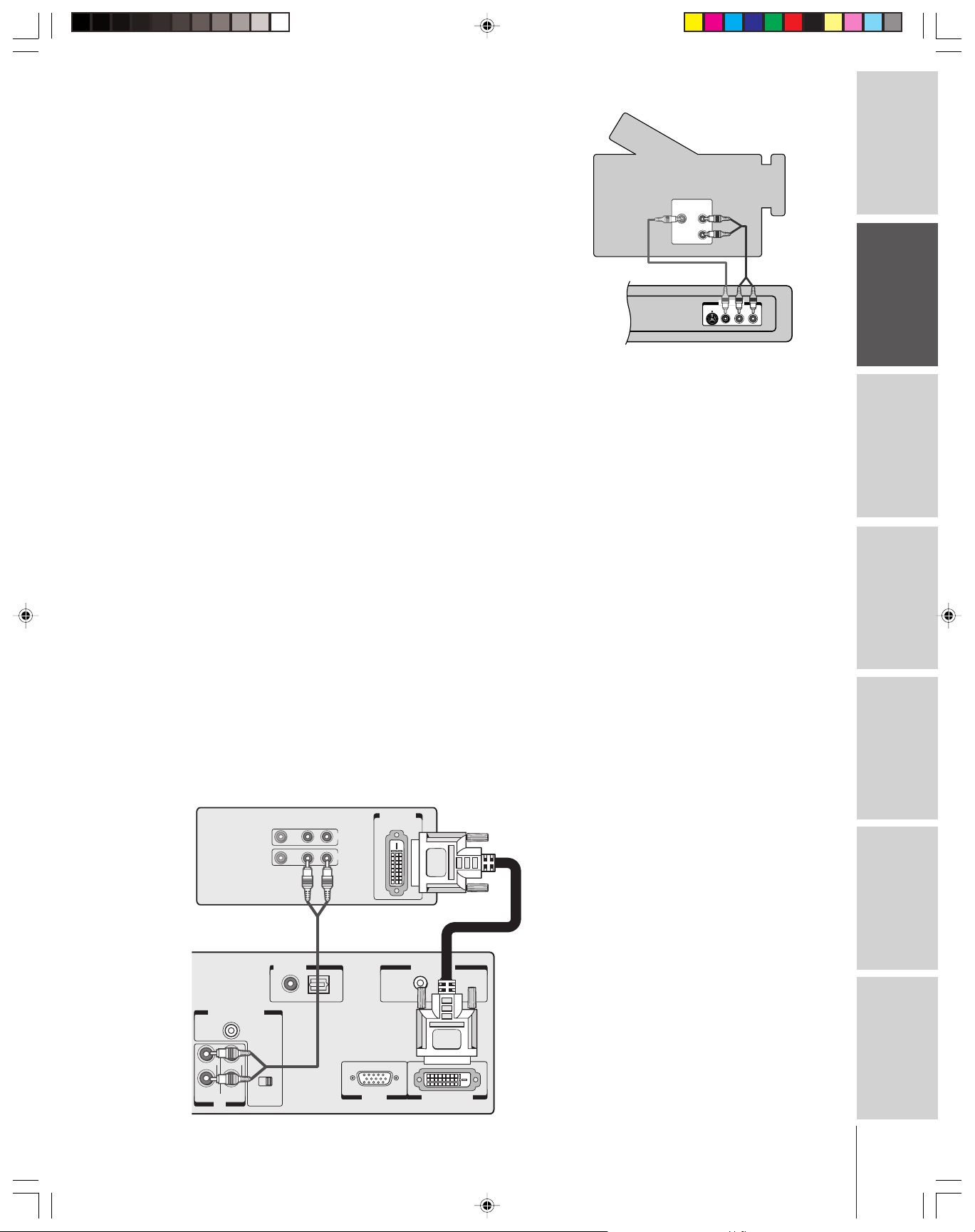
Connecting a camcorder
This connection allows you to watch video materials recorded on a
camcorder.
You will need:
• one set of standard A/V cables
Note: If you have an S-VHS camcorder, use an S-video
cable instead of a standard video cable. Do not connect
both a standard video cable and an S-video cable at the
same time, or the picture performance will be
unacceptable.
Connecting a device to the DVI/HDCP IN
terminal
Camcorder
VIDEO
AUDIO
OUT
L
R
VIDEO-3 IN
AUDIO
S-VIDEO
VIDEO
L/MONO R
Video-3 (front panel)
Introduction
Connecting
your TV
Remote Control
Using the
Your TV’s DVI/HDCP* IN terminal is designed to accept HDCP
program material in digital form from EIA/CEA-861–compliant**
consumer electronic devices, such as a set-top box or DVD player
equipped with a DVI-D digital single-link OUT terminal.
†
The DVI/HDCP IN terminal is designed for best performance with
1080i high-definition video signals, but also will accept and display
480p, 720p, and 480i picture signals.
The DVI/HDCP IN terminal is not intended for connection to and
should not be used with a PC (personal computer). For PC
connection, see “Connecting a computer” on page 18.
You will need:
• one DVI-D digital single-link cable
Note: For proper operation, the DVI-D cable length should
not exceed 3m (9.8 ft). The recommended length is 2m (6.6 ft).
• one pair of standard audio cables (or one digital audio cable, if
applicable; see pages 14, 53, and 57 for details on digital audio
connection)
DVI/HDCP device
(for example, set-top box or DVD player)
VIDEO AUDIO
LR
IN
OUT
DVI/ HDCP
OUT
* DVI/HDCP = Digital Visual Interface/
High-bandwidth Digital Content Protection.
** EIA/CEA-861 compliance covers the
transmission of uncompressed digital
video with high-bandwidth digital content
protection, which is being standardized for
future reception of high-definition video
signals.
† Consult your consumer electronics dealer
for availability.
Note:
• Make sure the DVI cable is fastened
securely to the TV and DVI device.
If the cable is not fastened securely on both
ends, the TV may suffer from picture noise
(“snow”) or have no picture at all.
• To ensure that the DVI/HDCP device is
reset properly, it is recommended that you
follow these procedures:
a) When turning on your electronic devices,
turn on the TV first, and then the
DVI/HDCP device.
b) When turning off your electronic devices,
turn off the DVI/HDCP device first,
and then the TV.
Setting up
your TV
Using the TV’s
Features
Appendix
TV
AUDIO CENTER
CHANNEL IN
L
RLR
For
DVI / HDCP
For PC
IN
57HLX82(E)08-18 10/29/02, 10:28 AM15
ON OFF
DIGITAL
AUDIO IN
COAXIAL OPTICAL
IR BLASTER
IN
OUT
PC IN DVI / HDCP IN
Index
15
MENU VOLUME CHANNEL EXIT TV/VIDEO POWER
IR receiver/repeater
or home theater
control system
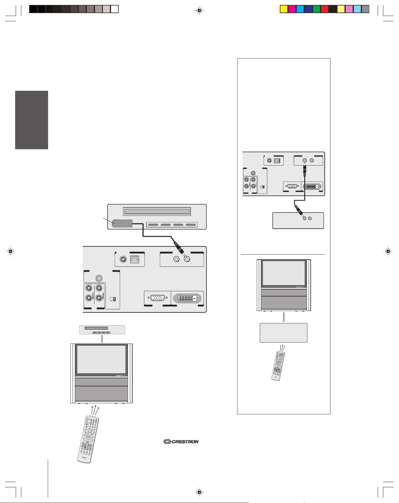
Connecting a device to the IR blaster
The IR blaster allows you to remotely operate (through the TV)
most infrared-controlled devices* (such as a Toshiba infrared-
Introduction
controlled VCR or DVD player) enclosed within an entertainment
center or similar cabinet. Without the IR blaster, the device typically
would need to be visible to operate it remotely.
You can use the TV’s remote control (programmed to operate
the device; see pages 19–25) or the device’s remote control. Point
the remote control at the front of the TV and press the button for the
desired function. The signal passes from the remote control through
the TV to the device via the IR blaster cable (included with your TV).
your TV
Connecting
To connect, align the IR blaster cable’s infrared “eye” with the device’s
infrared sensor and attach it using double-sided mounting tape
(included with the cable in the accessory pack). Plug the other end of
the IR blaster cable into the TV’s IR BLASTER OUT terminal.
You will need:
Using the
Remote Control
IR blaster cable’s
• one IR blaster cable (included)
• one piece of double-sided mounting tape (included)
Front of infrared-controlled device*
(such as a Toshiba infrared-controlled
VCR or DVD player)
infrared “eye”
facing device’s
infrared sensor
For additional control options for your
home theater system, you can connect
an IR receiver/repeater (not included)
or a home theater control system (not
included) to the TV’s IR BLASTER IN
terminal.*
See the Specifications section in the
back of this manual for IR BLASTER IN
terminal requirements.
Contact your home theater electronics
dealer for details about home theater
control systems.
Back of TV
AUDIO CENTER
For
DVI / HDCP
CHANNEL IN
L
RLR
For PC
IN
ON OFF
DIGITAL
AUDIO IN
COAXIAL OPTICAL
IR BLASTER
IN
OUT
PC IN DVI / HDCP IN
IN
OUT
your TV
Setting up
Features
Using the TV’s
Appendix
Back of TV
AUDIO CENTER
CHANNEL IN
RLR
For
DVI / HDCP
For PC
IN
L
ON OFF
DIGITAL
AUDIO IN
COAXIAL OPTICAL
MENU VOLUME CHANNEL EXIT TV/VIDEO POWER
IR BLASTER
IN
OUT
PC IN DVI / HDCP IN
With this connection, point the
Toshiba TV remote control at
the front of the TV to operate both
the TV and the infrared-controlled
device. (You also can point the
device’s remote control at the TV to
operate the device, but you also will
need to use the TV’s remote control
to operate the TV.)
Back of IR receiver/
repeater or home
theater control system*
(not included)
With this connection, point the Toshiba TV
remote control at the front of the
IR receiver/repeater or home theater
control system to operate the TV.
Index
57HLX82(E)08-18 10/29/02, 10:28 AM16
16
___________
*The IR blaster OUT function has been verified for use with Toshiba infrared-controlled devices. The IR blaster IN function
has been verified for use with
SmarTouch™ STS/STS-C wireless RF control systems. Due to the wide
variation in remote control operation among manufacturers, these functions may or may not operate with other brands.
SmarTouch is a trademark of Crestron Electronics, Inc. (www.crestron.com).
Introduction
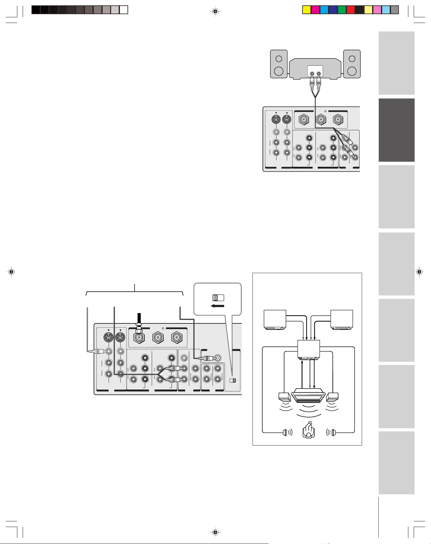
Connecting an audio system
This connection allows you to hear the TV sound through external
speakers connected to an audio amplifier.
To control the audio through the amplifier, turn on the TV and the
amplifier, set the volume of both to a moderate level, and turn off the
TV’s built-in speakers (see “Turning off the built-in speakers” on
page 55).
You will need:
• one pair of standard audio cables
Note:
If the volume of either the TV or the amplifier
is set to 0 (or OFF), you will not hear any sound.
Connecting an A/V receiver
This connection allows you to use an A/V (audio/video) receiver to
enhance your TV’s sound.
®
If you have a system with Dolby Pro Logic
add to the realism of the sound by using the TV’s internal speakers as
center channel speakers.
You will need:
• one set of standard A/V cables
• one single standard audio cable for the audio center channel
surround sound, you can
Amplifier
LINE IN
LR
TV
)
S-VIDEO
VIDEO
L/
MONO
AUDIO
R
VIDEO 1 VIDEO 2
L
AUDIO
R
COLOR
STREAM HD-1
IN
ANT( 75
ANT-1 OUT ANT-2
Y
P
B
P
R
IN OUT
L
AUDIO
R
COLOR
STREAM HD-2
Y
P
B
P
R
VIDEO
L/
MONO
AUDIO
R
Caution:
To avoid damaging the speakers:
• Turn off the TV before connecting or
disconnecting the Audio Center Channel
cable.
• Do not connect from the A/V receiver’s
Center Speaker OUT terminal (amplified
signal) to the TV’s Audio Center Channel
IN terminal.
L
R
VAR
AUDIO
Connecting
your TV
Remote Control
Using the
Setting up
your TV
To A/V receiver
Video
OUT
TV
S-VIDEO
VIDEO
L/
MONO
AUDIO
R
TV
IN
VIDEO 1 VIDEO 2
IN
From
Antenna
ANT( 75
ANT-1 OUT ANT-2
Y
P
L
AUDIO
R
COLOR
STREAM HD-1
B
P
R
IN OUT
)
L
AUDIO
R
COLOR
STREAM HD-2
Center
OUT
VIDEO
Y
L/
MONO
P
B
AUDIO
P
R
R
L
R
Note:
Refer to the instructions provided with your A/V receiver
for details about your surround sound system.
When the Audio Center Channel ON/OFF switch is in
the ON position, the TV speakers will function only as
center channel speakers.
Adjust the volume for the center channel speakers
using the center level control on the A/V receiver.
To use the TV speakers as normal speakers, set the
Audio Center Channel ON/OFF switch to the OFF
position.
ON OFF
AUDIO CENTER
CHANNEL IN
L
R
VAR
For
AUDIO
DVI / HDCP
For PC
IN
L
ON OFF
R
Dolby Pro Logic* surround sound
system connection example
Audio Video
VCR
Video
A/V receiver
Audio
Video
Left
speaker
T V
Surround
speaker L
_________
* Dolby and Pro Logic are registered
trademarks of Dolby Laboratories.
Audio
Audio
LDP/DVD
center
channel
Surround
speaker R
Right
speaker
Using the TV’s
Features
Appendix
Index
17
57HLX82(E)08-18 10/29/02, 10:28 AM17
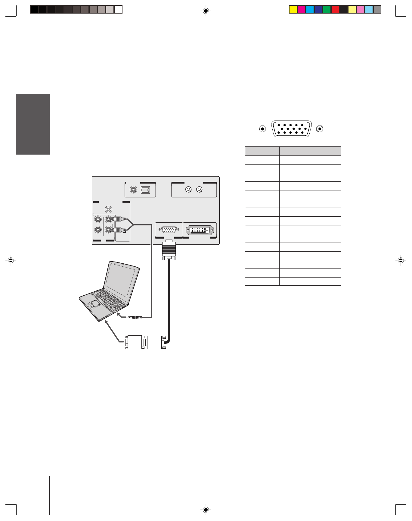
Connecting a computer
You can connect an analog RGB (15-pin) computer video cable to the
PC IN terminal on the TV.
Introduction
The following signals can be displayed:
You will need:
your TV
Connecting
Using the
Remote Control
your TV
Setting up
•VGA: 640 x 480/60 Hz (VESA 480-60)
•SVGA: 800 x 600/60 Hz (VESA 640-60)
•XGA: 1024 x 768/60 Hz (VESA 768-60)
• one computer video cable (D-sub 15-pin)
• one conversion adapter (the adapter is not necessary if you are
using a DOS/V compatible D-sub 15-pin terminal.
• audio cable for TV-to-PC connection
TV
AUDIO CENTER
CHANNEL IN
RLR
For
DVI / HDCP
IN
L
ON OFF
For PC
Computer
DIGITAL
AUDIO IN
COAXIAL OPTICAL
PC IN DVI / HDCP IN
IR BLASTER
IN
OUT
Note:
Some computer models cannot be connected
to this TV.
Pin layout for PC IN video terminal
5
10
15
11
1
6
Pin No. Signal
1R
2G
3B
4NC (not connected)
5NC
6 Ground
7 Ground
8 Ground
9NC
10 Ground
11 NC
12 NC
13 H-sync
14 V-sync
15 NC
Features
Using the TV’s
Appendix
Index
18
Audio cable for
TV-to-PC connection
Conversion
adapter
(if necessary)
57HLX82(E)08-18 10/29/02, 10:28 AM18
Using the remote control
Introduction
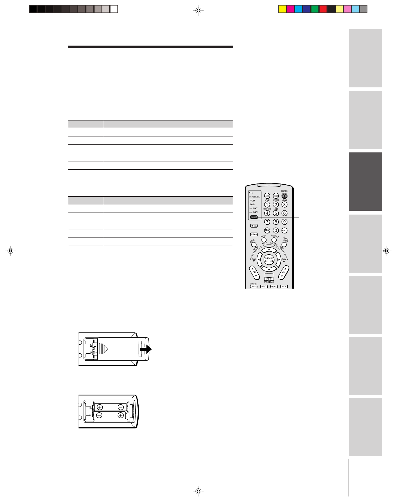
Preparing the remote control for use
Your Toshiba TV remote control has one dedicated TV mode and five
universal modes: VCR, Cable/SAT, DVD, Audio1, and Audio2. The
target devices and default devices being programmed for each mode
are as follows:
Target device/Mode mapping
Mode Device
TV Toshiba TV
CABLE/SAT Universal Cable, Satellite
VCRUniversal VCR, DVD, LD, Cassette
DVDUniversal DVD, VCR, LD, Cassette
AUDIO1 Universal Audio: Amp., Tuner, Misc.Audio, CD/MD
AUDIO2 Universal Audio: CD/MD, Amp., Tuner, Misc.Audio
Default device codes
Mode Default device
TV Toshiba TV
CABLE/SAT Toshiba Satellite receiver
VCRToshiba VCR
DVDToshiba DVD
AUDIO1 Pioneer Audio receiver
AUDIO2 Pioneer LD
Note:
Your TV’s remote control may not operate
certain features on your VCR, cable TV
converter, or other electronic device.
Refer to the owner’s manuals for your other
devices to determine their available features.
If your TV’s remote control does not operate a
specific feature on a device, use the remote
control that came with the device.
MODE
Connecting
your TV
Remote Control
Using the
Setting up
your TV
Repeatedly press MODE to cycle among the modes. If you own
different brands of audio/video devices, you must first program your
remote control (see “Programming the remote control for use with
your audio/video devices” on page 22).
Installing the remote control batteries
To install the batteries:
1. Slide the battery cover off the back of the remote control.
2. Install two “AA” size alkaline batteries. Match the + and – signs
on the batteries to the signs on the battery compartment.
Caution:
• Dispose of batteries in a designated
disposal area. Do not throw batteries into
afire.
• Do not mix battery types or combine used
batteries with new ones.
• If the batteries are dead or if you will not
use the remote control for a long time,
remove the batteries to prevent battery acid
from leaking into the battery compartment.
Note:
• Battery life expectancy is about one year
with normal use.
Using the TV’s
Features
Appendix
Index
3. Slide the battery cover back on to the remote control until the
lock snaps.
57HLX82(E)19-26 10/29/02, 10:28 AM19
19
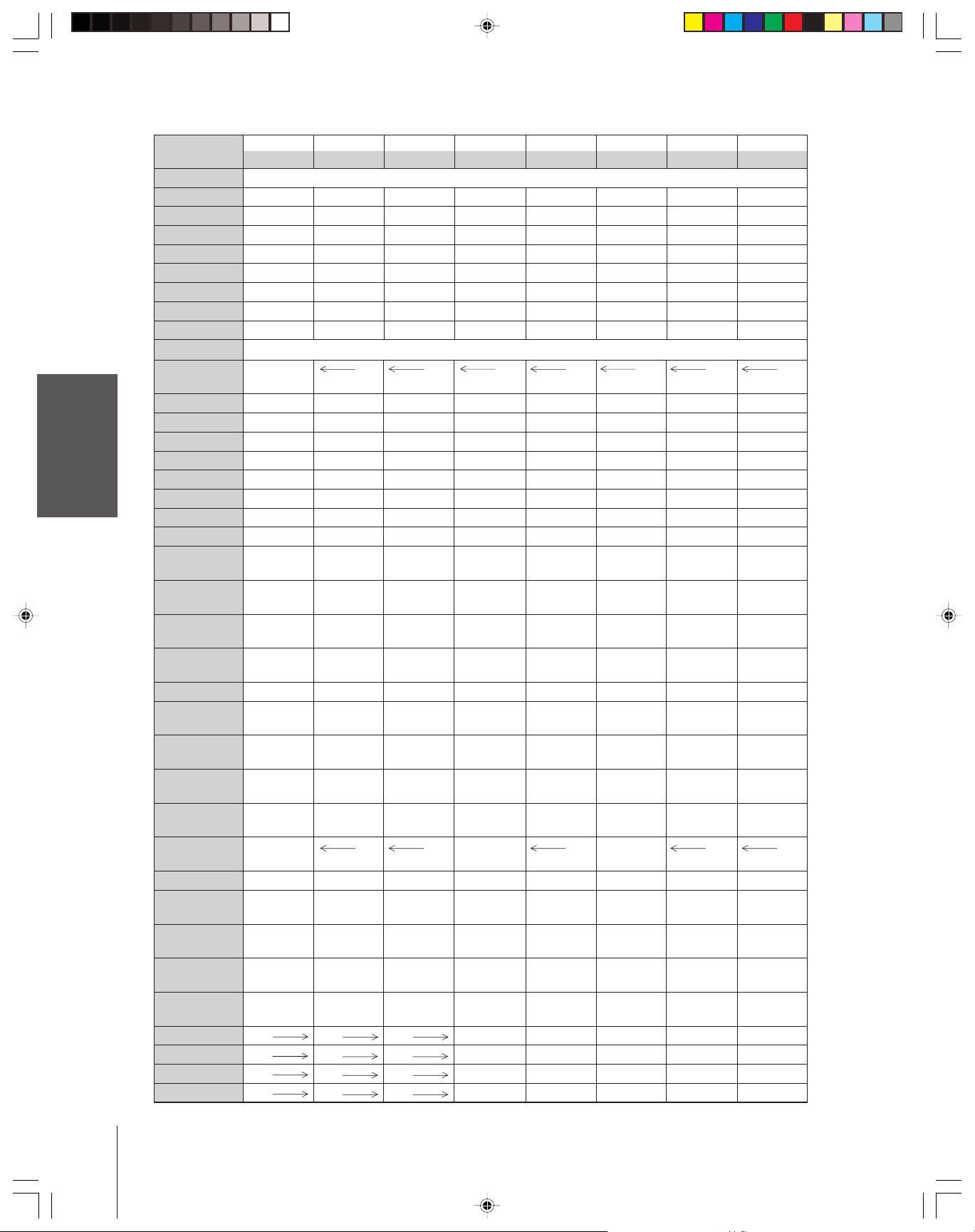
Remote Control functional key chart
Introduction
your TV
Connecting
Using the
Remote Control
your TV
Setting up
Features
Using the TV’s
Appendix
Index
LIGHT Lights the remote key, and toggles between enabled and disabled Illumination mode.
SLEEP Sleep timer --- --- --- --- --- --- --POWER Power Power Power Power Power Power Power Power
1/MOVIE Digit 1 Digit 1 Digit 1 Digit 1 Digit 1 AV input 1 Digit 1 Digit 1
2/SPORTS Digit 2 Digit 2 Digit 2 Digit 2 Digit 2 AV input 2 Digit 2 Digit 2
3/NEWS Digit 3 Digit 3 Digit 3 Digit 3 Digit 3 AV input 3 Digit 3 Digit 3
4/SERVICES Digit 4 Digit 4 Digit 4 Digit 4 Digit 4 AV input 4 Digit 4 Digit 4
5/LIST Digit 5 Digit 5 Digit 5 Digit 5 Digit 5 CD Digit 5 Digit 5
6Digit 6 Digit 6 Digit 6 Digit 6 Digit 6 Tuner Digit 6 Digit 6
MODE Remote control device mode selection
PIC SIZE Selects the TV TV TV TV TV TV TV
7Digit 7 Digit 7 Digit 7 Digit 7 Digit 7 Phono Digit 7 Digit 7
8Digit 8 Digit 8 Digit 8 Digit 8 Digit 8 Cassette Digit 8 Digit 8
9Digit 9 Digit 9 Digit 9 Digit 9 Digit 9 Aux Digit 9 Digit 9
ACTION --- --100/– 100 --- 100 100 100 100 100 100
0Digit 0 Digit 0 Digit 0 Digit 0 Digit 0 Digit 0 Digit 0 Digit 0
ENT --- CH Enter CH Enter CH Enter --- --- --- --GUIDE/SETUP
INFO/TITLE --- --- INFO --- TITLE= --- --- ---
FAVORITE/ Favorite CH --SUBTITLE
ALPHASORT/ --- --- Alphasort --- Audio --- --- --AUDIO
MENU/ Menu open/ --- Select --- Enter --- --- --ENTER Enter
yz Menu select --- Menu select --- Menu select --- --- ---
x •/FAV zy Menu select/ --- Menu select --- Menu select --- --- ---
VOL yz Volume Volume Volume Volume Volume Volume Volume ---
EXIT/ Exit Exit Exit Exit DVD clear Exit/Clear Exit/Clear Exit/Clear
DVD CLEAR
CH
INPUT TV/Video TV TV VCR input TV Input TV TV
MUTE
RECALL On-screen
CH RTN/ Previous Previous Previous Previous DVD --- --- --DVD RTN channel channel channel channel return
SLOW/
DIR x--- --- --- --- Reverse --- --- ---
SKIP/
SEARCH x--- --- --- --- Reverse
REW VCR VCR VCR Rewind Rewind Rewind Rewind Rewind
PAUSE/STEP VCR VCR VCR Pause Pause Pause Pause Pause
PLAY VCR VCR VCR Play Play Play Play Play
FF VCR VCR VCR F. Forward F. Forward F. Forward F. Forward F. Forward
Key Label
yz Channel Channel Channel Channel --- Channel --- ---
Toshiba TV Cable Satellite VCR DVD/LD Receiver CD/MD Cassete
(TV) (CBL/SAT) (CBL/SAT) (AUDIO) (AUDIO) (VCR)
image shape.
Action, Menu
--- --- Guide --- DVD setup --- --- ---
Favorite CH
FAV zy
up/down* up/down* up/down* up/down* up/down* up/down* up/down*
up/down up/down up/down up/down up/down
select
Sound mute* Sound mute* Sound mute* Sound mute* Sound mute* Sound mute* Sound mute*
---
display display display display
•
--- --- --- Forward Forward --- --- ---
•
--- --- --- --- Forward
On-screen On-screen On-screen --- --- ---
--- Menu --- --- ---
Top menu
--- Subtitle --- --- ---
---
---
Forward Forward
Reverse Reverse
---
20
57HLX82(E)19-26 10/29/02, 10:28 AM20
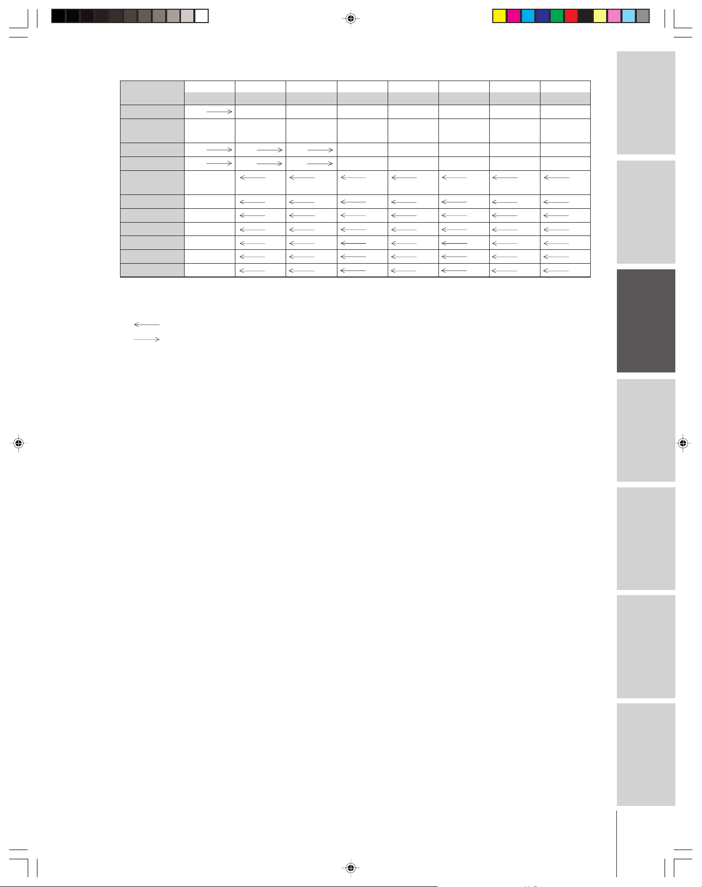
Introduction
Key Label
TV/VCR VCR
AM/FM DISC --- --- --- --- Disc shift AM/FM Disc shift Deck side
STOP VCR VCR VCR Stop Stop Stop Stop Stop
REC
**
PIP CH
PIPPOP on/off TV TV TV TV TV TV TV
MULTI
STILL POP Still TV TV TV TV TV TV TV
SWAP POP Swap TV TV TV TV TV TV TV
LOCATE POP Locate TV TV TV TV TV TV TV
SOURCE POP Source TV TV TV TV TV TV TV
Notes:
•“---” will send nothing.
•“ TV” will jump to TV.
•“ VCR” will jump to last active VCR or DVD. Active VCR/DVD is defined as the mode that remains for a minimum of
*
**
yz
5 seconds, or if a key is pressed in that mode.
The VOLUME and MUTE will jump to “TV” by default. When the volume is unlocked, all the devices will have their own volume.
The AUDIO1/2 (Receiver, CD) modes will have their own volume even if Volume Lock is on TV, CABLE/SAT, VCR, or DVD.
See “Using the Volume Lock feature” on page 23.
Press the REC button two times within 5 seconds to record each A/V source.
Toshiba TV Cable Satellite VCR DVD/LD Receiver CD/MD Cassete
(TV) (CBL/SAT) (CBL/SAT) (AUDIO) (AUDIO) (VCR)
---
VCRVCR VCR Record** --- Record** Record** Record**
POP channel TV TV TV TV TV TV TV
up/down
Strobe TV TV TV TV TV TV TV
TV/SAT TV/VCR --- --- --- Reverse
A/B switch
Connecting
your TV
Remote Control
Using the
Setting up
your TV
Using the TV’s
Features
Appendix
Index
57HLX82(E)19-26 10/29/02, 10:28 AM21
21
Programming the remote control for use with
your audio/video devices
Introduction
your TV
Connecting
Using the
Remote Control
Device code setup
1. Refer to the device code table on pages 24–25 to find the code for
the brand of your device.
If more than one code is listed, try each one separately until you
find the one that works.
2. Press MODE until the Mode indicator of the device
(CABLE/SAT, VCR, DVD, AUDIO1, AUDIO2) lights up.
3. While holding down the RECALL button, press the Channel
Number buttons to enter the four-digit code for your brand of
device. If a valid code is entered, the mode indicator will blink
twice. If an invalid code is entered, the mode indicator will blink
one long blink.
4. Point the remote control at the device and press POWER to test
the code.
If the device turns on, you have entered the correct code.
If the device does not respond to the remote control, you may
have entered the wrong code. Repeat steps 3 and 4 using another
code.
5. Press MODE to select the TV mode to control the TV.
Note:
• Every time you replace the batteries, you
must reprogram the remote control.
• Some newer VCRs are capable of working
on either of two remote codes. These VCRs
have a switch labeled “VCR1/VCR2.”
If your VCR has this kind of switch and
does not respond to any of the codes for
your VCR brand, set the switch to the other
position (VCR1 or VCR2) and reprogram
the remote control.
your TV
Setting up
Features
Using the TV’s
Appendix
Searching and sampling the code of a device (8500)
If you do not know the device code for a particular device, you can
cycle the remote control through the available codes for that device
mode and sample the functions to find the code that controls the
target device. The keys available to be sampled (if applicable to that
mode), are POWER, 1, VOL y, CH y, and PLAY. Invalid keys will
be ignored while in program mode.
To cycle through each available device code and sample its functions:
1. Press MODE to select the mode you want to set up.
2. While holding down the RECALL button, press 8 –5 –0 –0.
The remote control will enter program mode.
3. Point the remote control at the target device and press POWER
(or other function buttons that are available to be sampled).
4. If the device responds to the remote control:
Press RECALL to store the device code.
The mode indicator will blink twice and the remote control
will exit the program mode.
If the device does not respond to the remote control:
Press y, and then press POWER.
Repeat this step until the device responds to the remote
control, and then press RECALL.
Note: When a search cycle is completed, the mode indicator will blink
three times. The remote control will begin to cycle through the
available codes again. If no key is pressed within 10 seconds while
programming, the remote control will exit the program mode and
return to the previous code.
POWER
Numbers
MODE
y
RECALL
Index
22
57HLX82(E)19-26 10/29/02, 10:28 AM22
 Loading...