

Page 1
SERVICE MANUAL
Projection Television
56HM66 Rev.1
For Technical Bulletins, Technical Tips, or other information regarding the
service of this model, visit the Toshiba America Consumer Products National
Service Division website at:
www7.toshiba.com
This model is classified as a green product (*1), as indicated by the underlined serial number.
This Service Manual describes replacement parts for the green product. When repairing this
green product, use the part(s) described in this manual and lead-free solder (*2).
For (*1) and (*2), refer to GREEN PRODUCT PROCUREMENT and LEAD-FREE
SOLDER.
© TOSHIBA CORPORATION 2008
Page 2
IMPORTANT NOTICE
1
WARNING: Do not modify or alter the information or data provided herein without prior written consent by Toshiba.
Toshiba shall not be liable to anybody for any damages, losses, expenses or costs, if any, incurred in connection with or
as a result of such modification or alteration.
THE INFORMATION OR DATA HEREIN SHALL BE PROVIDED "AS IS" WITHOUT ANY WARRANTY OF ANY KIND, EITHER
EXPRESS OR IMPLIED WARRANTY OF MERCHANTABILITY AND FITNESS FOR A PARTICULAR PURPOSE.
Toshiba shall not be liable for any damages, losses, expenses or costs, if any, incurred in connection with or as a result of
use of any information or data provided herein.
GREEN PRODUCT PROCUREMENT
The EC is actively promoting the WEEE & RoHS Directives that define standards for recycling and reuse of Waste Electrical and
Electronic Equipment and for the Restriction of the use of certain Hazardous Substances. From July 1, 2006, the RoHS Directive will
prohibit any marketing of new products containing the restricted substances.
Increasing attention is given to issues related to the global environmental. Toshiba Corporation recognizes environmental protection
as a key management tasks, and is doing its utmost to enhance and improve the quality and scope of its environmental activities. In
line with this, Toshiba proactively promotes Green Procurement, and seeks to purchase and use products, parts and materials that
have low environmental impacts.
Green procurement of parts is not only confined to manufacture. The same green parts used in manufacture must also be used as
replacement parts.
LEAD-FREE SOLDER
WARNING: This product is manufactured using lead-free solder as a part of a movement within the consumer products industry at
large to be environmentally responsible. Lead-free solder must be used in the servicing and repair of this product.
The melting temperature of lead-free solder is higher than that of leaded solder by 86ºF to 104ºF (30ºC to 40ºC ). Use of a sold ering
iron designed for lead-based solders to repair product made with lead-free solder may result in damage to the component and or
PCB being soldered. Great care should be made to ensure high-quality soldering when servicing this product especially when
soldering large components, through-hole pins, and on PCBs as the level of heat required to melt lead-free solder is high.
SAFETY INSTRUCTION
WARNING: Before servicing this chassis, read the "Safety Precaution" and "Product Safety Notice" instructions below.
Safety Precaution
WARNING: Servicing should not be attempted by anyone unfamiliar with the necessary precautions on this receiver. The following
are the necessary precautions to be observed before servicing this chassis.
1. An isolation transformer should be connected in the power line between the receiver and the AC line before any service is
performed on the receiver.
2. Always disconnect the power plug before any disassembling of the product. It may result in electrical shock.
3. When replacing a chassis in the cabinet, always be certain that all the protective devices are put back in place, such as
nonmetallic control knobs, insulating covers, shields, isolation resistor-capacitor network, etc.
4. Always keep tools, product components, etc. away from children as these items may cause injury.
5. Depending on the model, use an isolation transformer or wear suitable gloves when servicing with the power on.
Disconnect the power plug to avoid electrical shock when replacing parts. In some cases, alternating current is also
impressed in the chassis, so electrical shock is possible if the chassis is contacted with the power on.
6. Always use the replacement parts specified for the particular model when making repairs. The parts used in products
require special safety characteristics such as inflammability; voltage resistance, etc. therefore, use only replacement parts
Page 3
that have these same characteristics. Use only the specified parts when the mark is indicated in the circuit diagram or
2
parts list.
7. Part mounting and wire routing should be the same as that used originally. For safety purposes, insulating materials such as
isolation tubes or tape are sometimes used and printed circuit boards are sometimes mounted floating. Also make sure that
wiring is routed and clamped to avoid parts that generate heat or use high voltage. Always follow the manufactures wiring
routes / dressings.
8. Always ensure that all internal wirings are in accordance before re-assembling the external casing after a repair is
completed. Do not allow internal wiring to be pinched by cabinets, panels, etc. Any error in reassembly or wiring can result
in electrical leakage, flame, etc., and may be hazardous.
9. NEVER remodel the product in any way. Remodeling can result in improper operation, malfunction, electrical leakage, or
flame, which may be hazardous.
10. Always perform an AC leakage current check on the exposed metallic parts of the cabinet such as antennas, terminals,
screw heads, metal overlays, control shafts, etc. to be sure that the set is safe to operate without any danger of electrical
shock before returning the set to the customer.
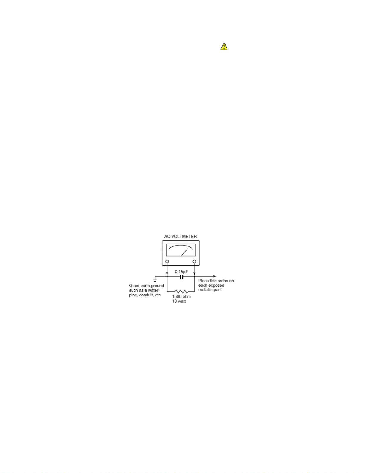
11. To check leakage current: (After completing the work, measure the leakage current to prevent an electrical shock.)
• Plug the AC line cord directly into a 120V AC outlet. Do not use an isolation transformer for this check.
• Use an AC voltmeter having 5000 ohms per volt or more sensitivity in the following manner.
Connect a 1500 ohm 10 watt resistor, paralleled by a 0.15 µF, AC type capacitor, between a known good earth ground (water pipe,
conduit, etc.) and the exposed metallic parts, one at a time. Measure the AC voltage across the combination of 1500 ohm resistor
and 0.15 µF capacitor. Reverse the AC plug at the AC outlet and repeat AC voltage measurements for each exposed metallic part .
Voltage measured must not exceed 0.3 volts rms. This corresponds to 0.2 milliamps AC. Any value exceeding this limit constitutes a
potential shock hazard and must be corrected immediately.
Product Safety Notice
Many electrical and mechanical parts in this chassis have special safety-related characteristics. These characteristics are often
overlooked in a visual inspection. The protection afforded by them cannot necessarily be obtained by using replacement
components rated for higher voltage, wattage, etc. Replacement parts which have these special safety characteristics are identified
in this manual and its supplements. Electrical components having such features are identified by the international hazard symbols
on the schematic diagram and the parts list. Before replacing any of these components, read the parts list in this manual carefully.
The use of substitute replacement parts which do not have the same safety as specified in the parts list may create electrical shock,
fire, or other hazards.
Page 4
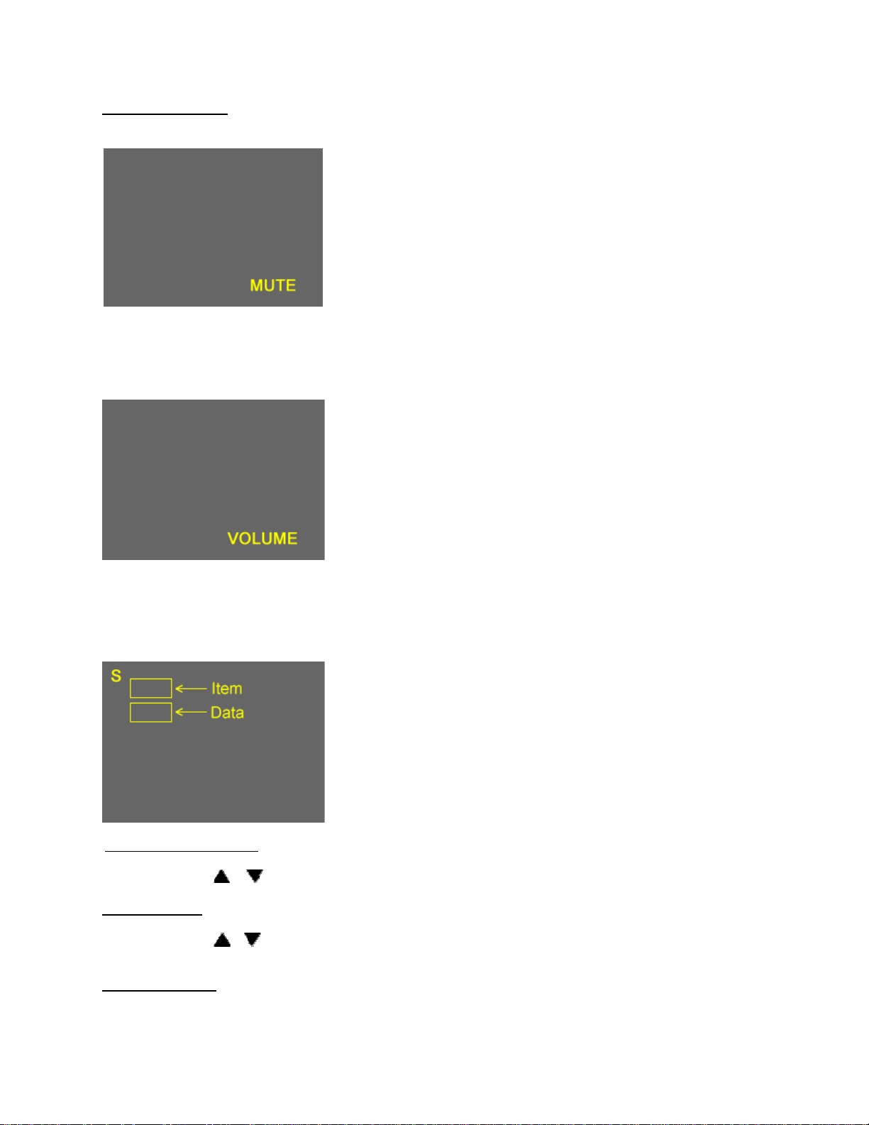
Entering Service Mode
3
1. Set VOLUME to minimum and press MUTE button twice on the remote
control.
↓
↓
Service Mode display
2. Press MUTE button again and hold button down.
3. While holding the MUTE button, press MENU button on TV set.
Selecting the Adjusting Item
Every pressing of CH
Adjusting the Data
Pressing of VOLUME
or button in the service mode changes the adjustment items.
or button will change the value of data in the range from 00H to FFH. The variable range depends on
the adjusting item.
Exiting Service Mode
Pressing POWER button to turn off the TV once.
Page 5
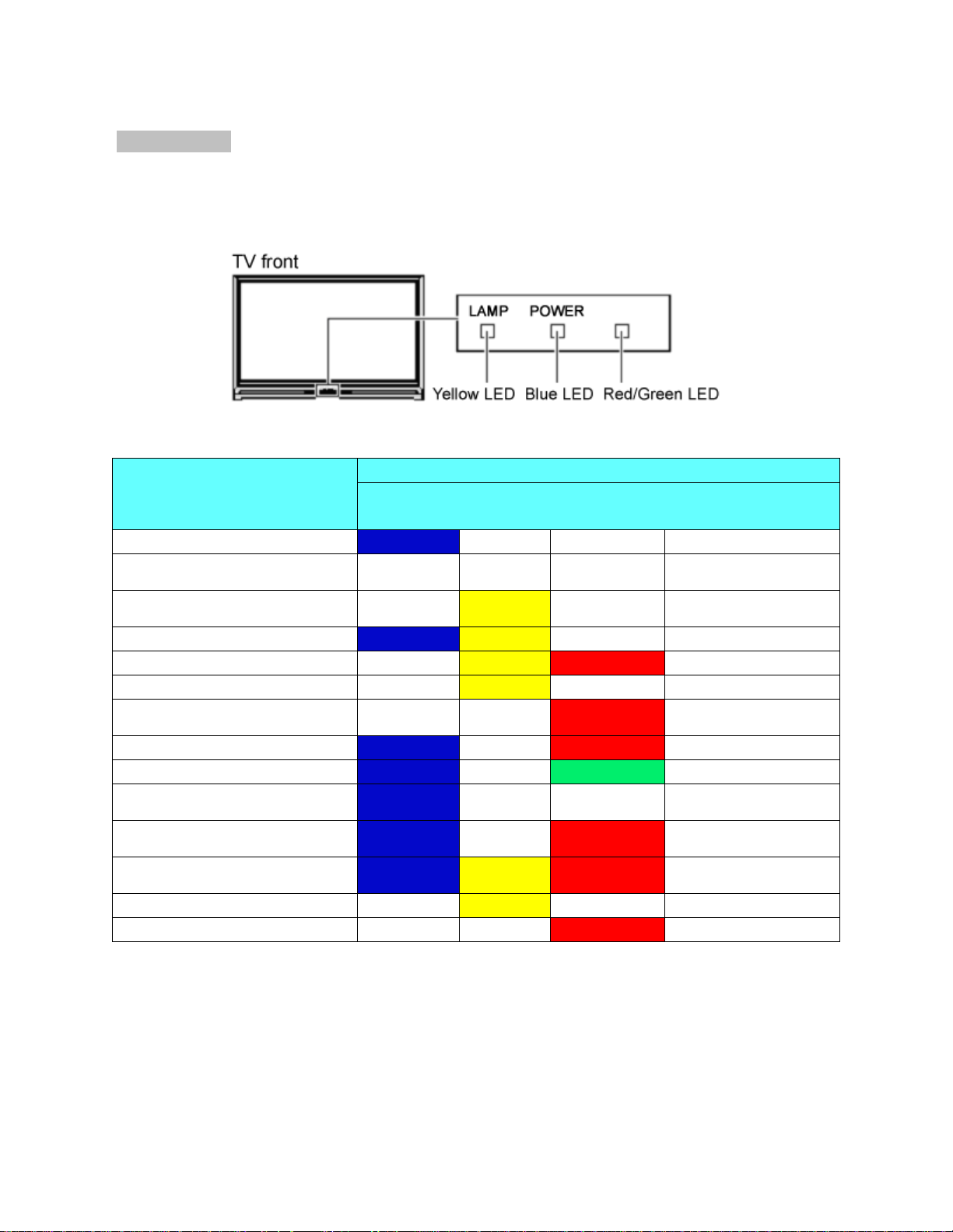
LED BLINK CODES
4
The yellow, blue, and red/green LED lights on the TV (at the bottom center of the TV) indicate the TV's status, as described below:
Note: If the TV loses A/C power (e.g., a power outage occurs or the power cord is unplugged), when power is restored, the yellow
LED will blink while the TV is booting until the remote control is usable. This is normal and is not a sign of malfunction.
50HM66/56HM66
MODE POWER LAMP TIMER ANNOUNCEMENT
POWER ON
POWER OFF (Standby w/ Quick
Restart OFF)
IN LPS (Standby w/ Quick
restart ON)
Waiting to re-light the lamp
Lamp won’t light
Open Lamp door
Fan Stop Detection (Light
Engine)
Fan Stop Detection (POD)
Fan Stop Detection (Ballast)
IIC BUS Error
Color wheel stop
Abnormal temperature in
Thermo Sensor
Seine Booting
SLEEP TIMER
BLUE YELLOW RED/GREEN VOICE
ON
ON Blinking
ON
ON
Blinking
ON Blinking
ON
YES
Blinking
Blinking
Blinking
YES
YES
YES
YES
Slow
blinking
YES
Fast
blinking
Blinking
YES
Fast
blinking Blinking Blinking
3 Blinks
ON
YES
Page 6
Replacing the Lamp Unit
5
WARNING: RISK OF ELECTRIC SHOCK! TO REDUCE THE RISK OF ELECTR IC SHOCK, NEVER REMOVE TV COVERS,
EXCEPT AS SPECIFIED HEREIN. REFER ALL SERVICING NOT SPECIFIED IN THIS MANUAL TO QUALIFIED SERVICE
PERSONNEL. Failure to follow this WARNING may result in death or serious injury.
The light source for this TV is a mercury lamp with internal atmospheric pressure that increases during use. The lamp has a limited
service life that varies depending on product use and user settings.
As is generally the case with all projection TVs that use projection lamps as a light source, the brightness of the lamp in this TV may
vary somewhat over the expected service life and will generally decrease over time. Because of the many variables that can affect
the useful service life of the lamp, your experience may vary from other users.
If you use the lamp beyond its service life you may notice a reduction in the colors and/or brightness of the picture. The strength of
the quartz glass in the lamp will be reduced and the lamp may rupture (often making a loud noise when this happens). If the lamp
ruptures, the TV will not operate until the lamp unit is replaced.
CAUTION: Always handle the lamp unit with care. The lamp unit in this TV was designed for safe replacement by consumers;
however, if the lamp unit is subjected to intentional abuse (such as excessive mechanical abuse or handling by children or pets), the
unit may break, exposing sharp edges or pinch points.
WARNING: RISK OF ELECTRIC SHOCK! TO REDUCE THE RISK OF ELECTRIC SHOCK, NEVER REMOVE TV COVERS,
EXCEPT AS SPECIFIED HEREIN. REFER ALL SERVICING NOT SPECIFIED IN THIS MANUAL TO QUALIFIED SERVICE
PERSONNEL. Failure to follow this WARNING may result in death or serious injury.
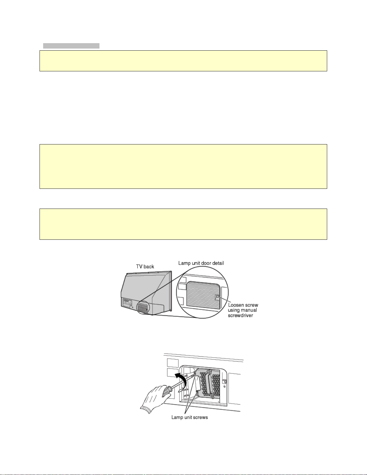
1. Turn off the TV and unplug the power cord.
WARNING: Eye damage may result from directly viewing the light produced by this lamp. Always turn off the TV and unplug
the power cord before opening the lamp unit door.
CAUTION! HOT SURFACE! Touching the lamp before it has cooled will result in severe burns. ALLOW THE LAMP TO
COOL FOR AT LEAST ONE (1) HOUR BEFORE REPLACING IT.
2. Using a manual, slotted screwdriver, loosen the screw securing the lamp door and remove the door.
3. Using a manual Phillips screwdriver, loosen the two screws on the lamp unit.
Page 7
WARNING: RISK OF ELECTRIC SHOCK! The lamp unit door is provided with an interlock to reduce the risk of electric
6
shock and excessive ultraviolet radiation. Never defeat its purpose or attempt to service without removing the lamp
unit door completely. Failure to follow this WARNING may result in death or serious injury.
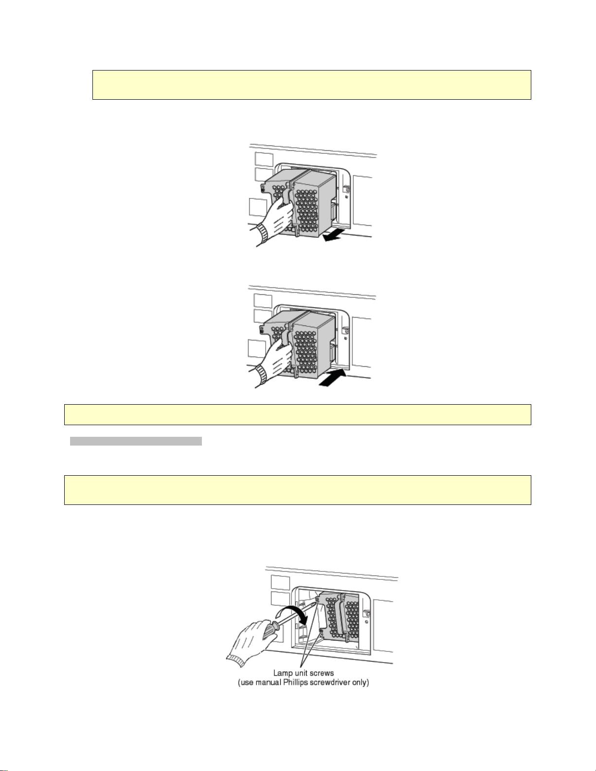
4. Grasp the lamp unit handle and gently pull the lamp unit straight out of the TV. Set the old lamp unit aside (-> "Disposing of
the used lamp unit" on Owners’ Manual). NOTE: Wear soft, lint-free gloves when replacing the lamp unit.
5. Carefully insert the new lamp unit straight into the TV until it is fully seated.
NOTE: Never subject the lamp unit to excessive shock. Never touch the lamp unit glass or otherwise get it dirty. Doing so may
affect the image quality and reduce the service life of the lamp. See "Cleaning the lamp unit glass" below.
CLEANING THE LAMP UNIT GLASS
If you accidentally touch the lamp unit glass or otherwise get it dirty, wipe it with a lint-free lens cleaning cloth (such as a cloth for
cleaning camera lenses or eyeglasses).
CAUTION: NEVER clean a hot lamp with any type of flammable liquid or aerosol cleaning agent. Many ordinary cleaning
agents (such as glass cleaners) contain chemicals that may be flammable at certain temperatures. If the lamp unit is not allowed to
cool for at least one (1) hour, such chemicals may ignite.
6. Using a manual Phillips screwdriver, tighten the two lamp unit screws. NOTE: Hand-tighten only. Do not use an electric
screwdriver. Make sure the lamp unit and screws are installed securely. Otherwise, the TV may no turn on and the
lamp life may be shortened.
Page 8
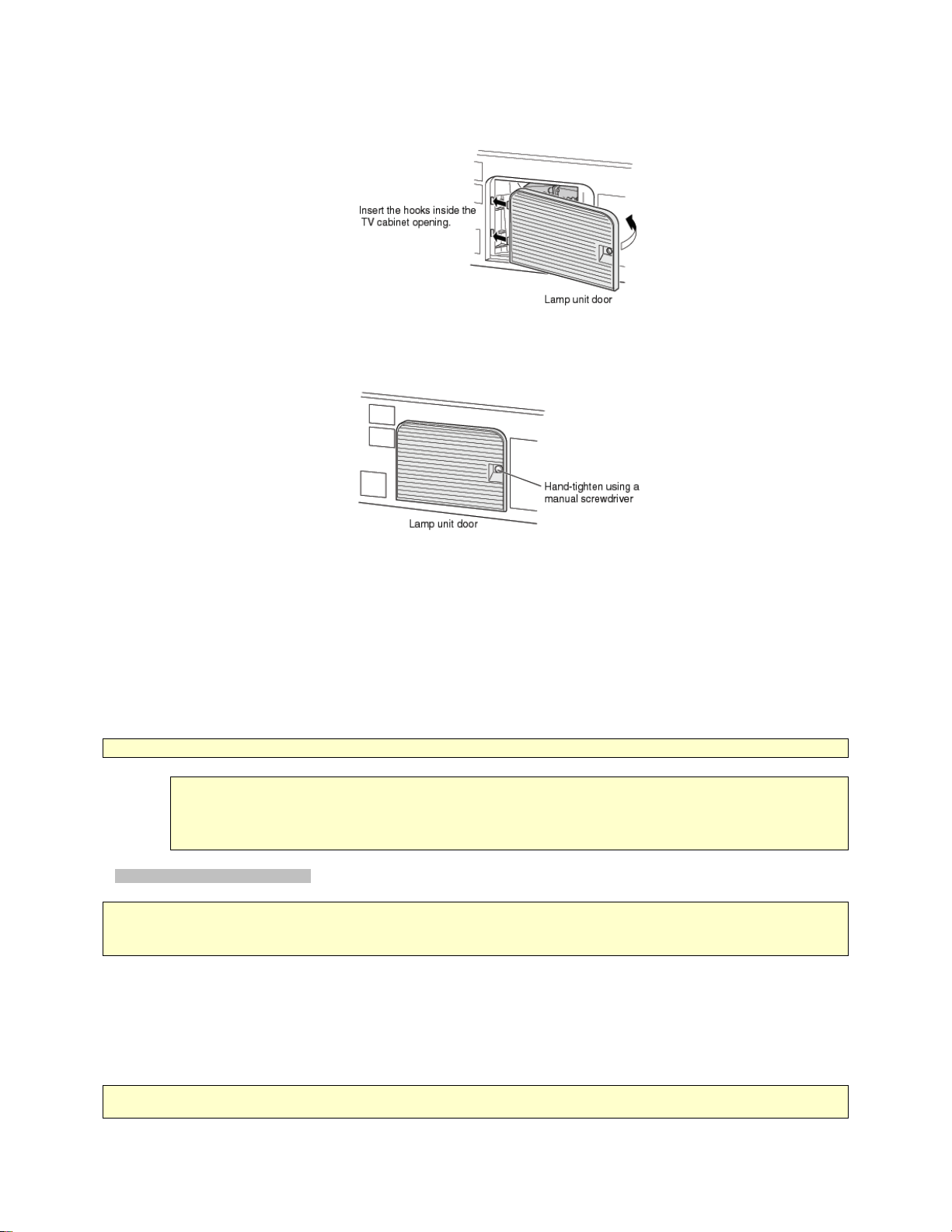
7. Reattach the lamp unit door, making sure to insert the hooks on the left side of the door inside the opening in the TV cabinet.
7
8. Replace the door screw and tighten using a manual screwdriver. NOTE: Make sure the lamp unit door is installed
securely; otherwise, the TV may not turn on.
9. Plug in the power cord and turn on the TV. After the initial warm-up period (which may take several seconds for full picture
brightness), the TV should operate normally. If any of the following conditions exist, turn off the TV, unplug the power cord,
and repeat steps 1-9 to ensure that the lamp unit and lamp unit door are installed correctly:
• No picture
• Dark picture
• TV will not turn on
NOTE: If, after repeating steps 1-9, the problem still exists:
• In the U.S., call TACP Consumer Solutions at 1-800-631-3811.
• In Canada, locate the nearest Toshiba authorized service depot by directing your web browser to www.toshiba.ca;
click "Home Entertainment", and then click "Support".
Disposing of the Used Lamp Unit
CAUTION: Always handle the lamp unit with care. The lamp unit in this TV was designed for safe replacement by consumers;
however, if the lamp unit is subjected to intentional or accidental abuse (such as excessive mechanical abuse or handling by
children or pets), the unit may break, exposing sharp edges or pinch points.
• Place the used lamp unit in the empty box from the new unit.
• Keep the lamp unit out of reach of children and pets.
• Dispose of the used lamp unit by the approved method for your area.
NOTE: The lamp unit contains mercury. Disposal of mercury may be regulated due to environmental considerations. For disposal
or recycling information, contact your local authorities or the Electronic Industries Alliance (www.eiae.org).
Page 9
_
_
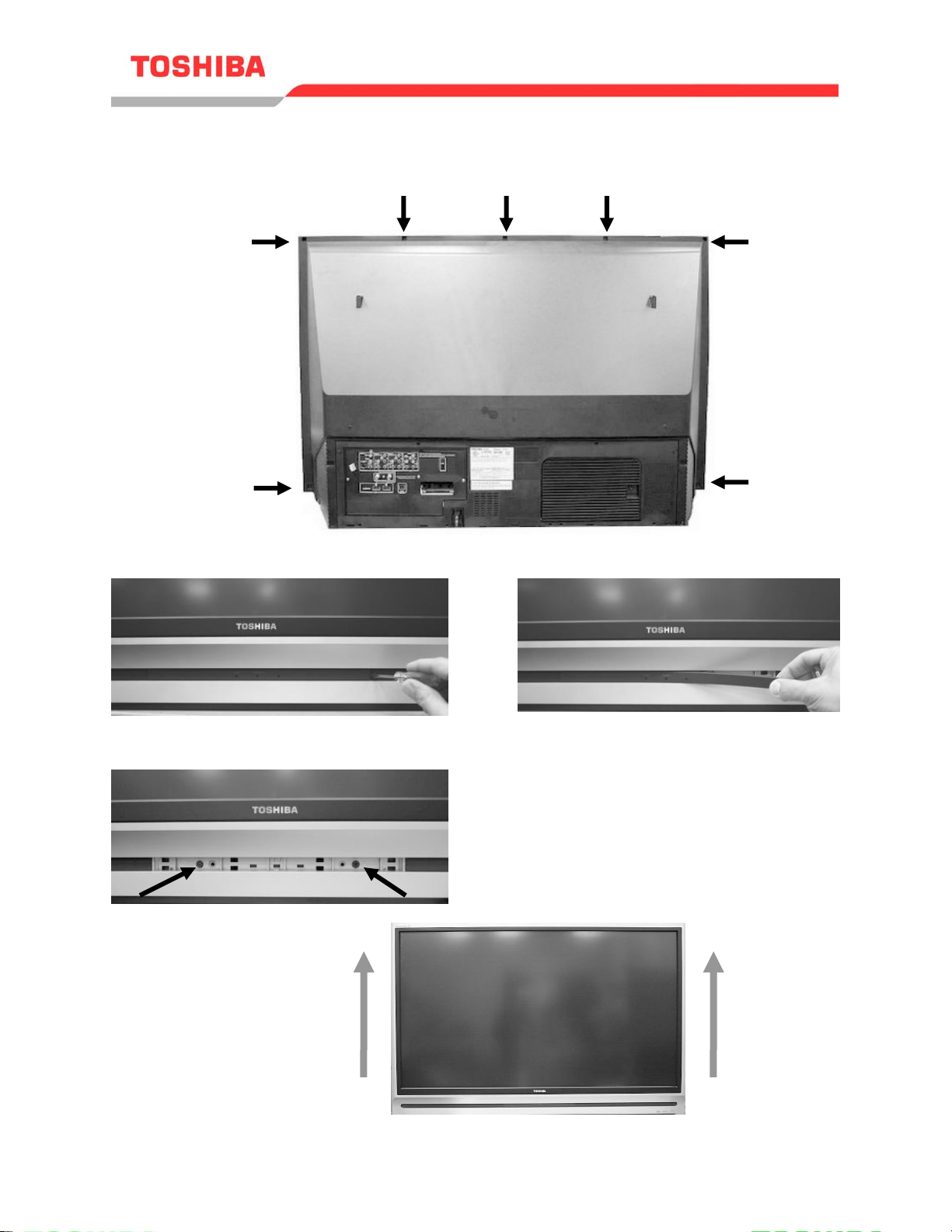
Front Bezel Removal
8
50HM66, 50HMX96, 56HM16, 56HM66, 56HMX96
1. Remove 7 Screws from cabinet Back
2. Remove Front Plate
3. Remove 2 Screws
4. Pull front Bezel up then out
____________________________________________________________________________
2007 Toshiba America Consumer Products, LLC. Page 10 of 12
SMART2006001_Version2.2
Page 10
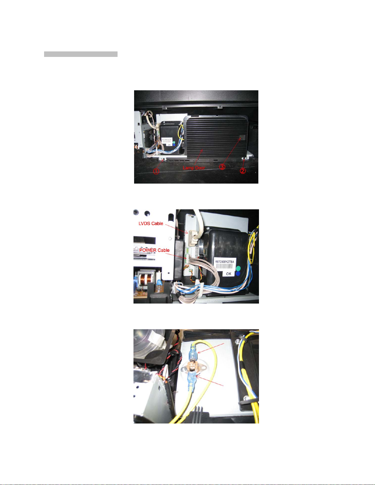
LIGHT ENGINE REPLACEMENT
9
1. Remove the back cover.
2. Remove the lamp cover by removing screws 1, 2, and 3.
3. Remove the LVDS and POWER cables.
4. Unfasten the thermostat lead wires. (Leave the thermostat Breaker.)
Page 11
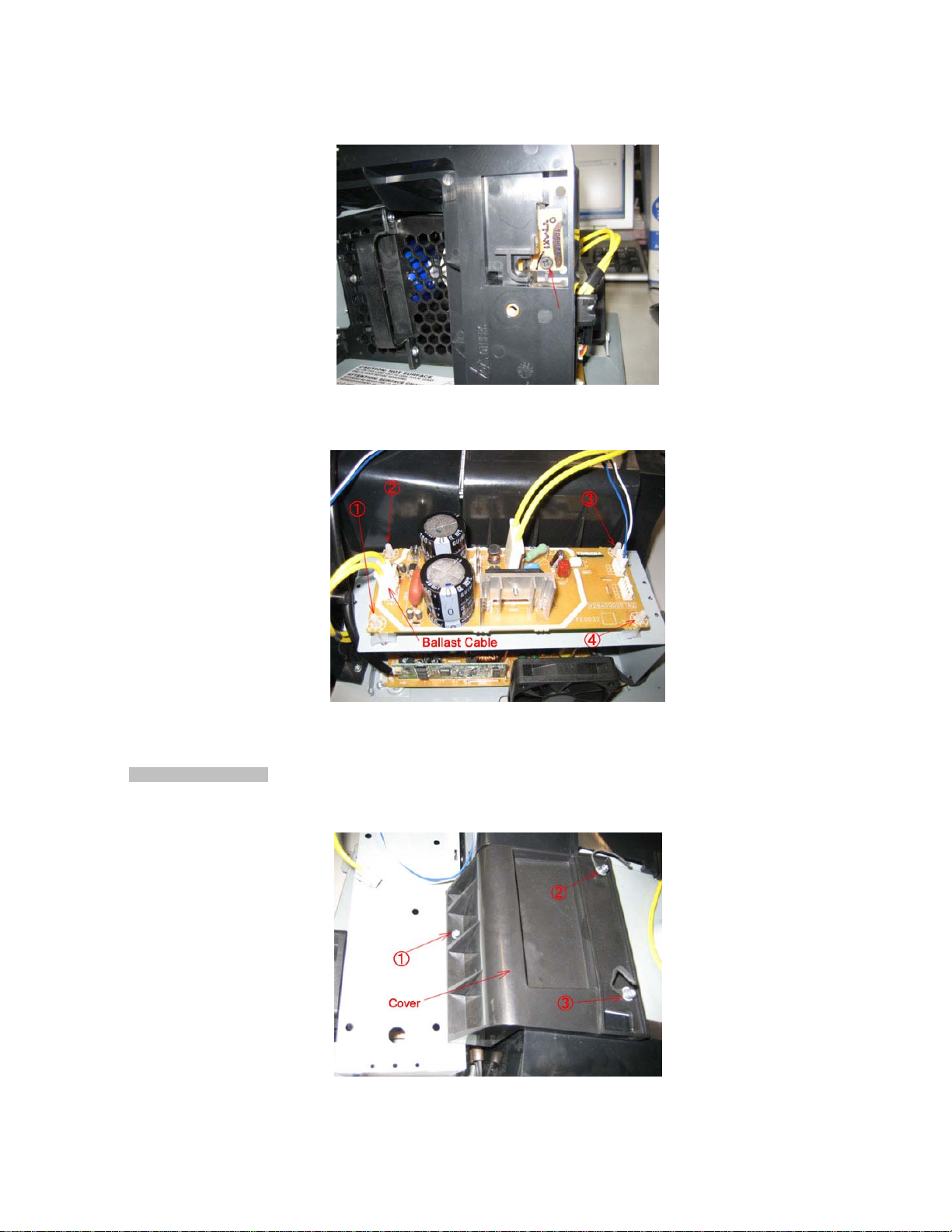
5. Remove the door SW unit by unscrewing as shown below.
10
6. Disconnect the ballast cable and remove the ballast unit from the retaining clips 1 - 4.
7. Remove the light engine. Reassemble the light engine by following steps 1 – 7 in reverse.
Lamp Fan Replacement
1. Remove screws 1, 2, and 3 securing the lamp fan cover and remove the lamp fan cover.
Page 12

2. Remove the Ballast Fan cable (1) and Lamp Fan cable (2).
11
3. Remove the 2 screws securing the Lamp fan and remove the lamp fan.
4. Remove the 4 rubber corners from the old lamp fan and place them on the new lamp fan.
5. Assemble the new fan to the light engine by following steps 1 – 4 in reverse.
Page 13

DMD Fan Replacement
12
1. Remove the DMD Fan cable.
2. Remove the DMD Fan casing by removing screws 1, 2, and 3.
3. Remove the 2 screws securing the LVDS connector.
Page 14

4. Remove the DMD shield case by removing screws 1 and 2.
13
5. Remove the DMD Fan by removing screws 1 and 2.
6. Assemble the new DMD fan by following steps 1 – 5 in reverse.
Ballast Fan Replacement
1. Remove the retaining pins from the fan.
Page 15

2. Replace the Ballast Fan.
14
3. Fix the Ballast Fan with two pins.
Thermostat Breaker Replacement
1. Disconnect the thermostat lead wires.
Page 16

2. Replace the Thermostat Breaker by removing the retaining screw.
15
(Thermostat Breaker is secured by 2 screws in some production units.)
3. Reconnect the thermostat lead wires.
Page 17

Troubleshooting Flowchart 2006 DLP
16
“Lamp Fails To Start” (Chart 1)
Lamp fails to light
Power the Set On
using the power
button
Repair Chassis Power
Supply and/or System
YELLOW - 1/2 second blink
BLUE - Solid
RED - Off
YELLOW - Solid
BLUE - Off
RED - Off
YELLOW - Solid
BLUE - Off
RED - .5 second blink
Control
No
Is a Power
No
Select LED Blink Sequence after
Relay Click
heard?
Yes
Do any of the
LED’s light or
blink?
Yes
pressing the Power Button
Trying to Light the Lamp (Chassis will try
this cycle about 8 times)
Lamp door is OPEN. Check Lamp Door Switch
and Cables between the Switch and Chassis
The lamp has failed to light after 8 attempts
Unit is Working OK
Yes
Did Lamp Light
within 8 Cycles?
No
Inspect Lamp
Assy / Substitute
Lamp
YELLOW - Off
BLUE - Off
RED - .5 second blink
YELLOW - Off
BLUE - 1 second blink
RED - Off
YELLOW - Off
BLUE - Solid
GREEN - .5 second blinks
UNKNOWN Sequence or No Sequence
One of the Optical Engine Fans Has Stopped
BUS Line Error. Refer to Chart 4
POD Fan Has Stopped
(Lamp will still light but has error Indication on
Screen)
Refer to Chart 4
Lamp
Defective?
No
Go To Chart 2
Yes
Replace LAMP
______________________________________________________________________________
2007 Toshiba America Consumer Products, LLC.
SMART2006001_Version2.2
Page 18

_
_
Troubleshooting Flowchart 2006 DLP
17
From Chart 1
Unplug the TV
from AC and
remove the back
cover
Remove 2 screws
holding the optic
engine in place
and slide back to
gain access.
V1.0
“Lamp Fails To Start” (Chart 2)
DMD Formatter PCB
See
Footnote 1.
Re-Apply AC and
Power the set on
using the power
button.
Does the Color
Wheel Start?
No
Check Ribbon Cable from
the Color Wheel to the
DMD Formatter Board.
Connector labeled [CW
OUT] on Formatter Metal
Shield
Problem
Resolved?
Yes
No
12v present on
J11 Pins 1,2?
Yes
Ballast Power Supply PCB
Approx 300v
present across
P811A?
Yes
Check for 5vdc on
pin 3 of plug CN3
on the Ballast
Board (5 pin plug)
Fig. 1
Is the 5vdc
present?
No
No Yes
Plug
CN3
Check Chassis
Power Supply
No
120vac across
P807B?
Pin 1
Pin 2
Pin 3
Pin 4
Pin 5
Fig. 1
Yes
Black
Brown
Red
Orange
Yellow
Reset Thermal
Sensor
Yes
Is Thermal
Sensor across
P805 Open?
No
Change Ballast
Power Supply
Go to Chart 3
Yes
No
Replacing the Light Engine under
Repair
Connections
Replace Optical
Engine
Warranty requires a concession number
to be obtained from Technical Support.
1-800-345-9785
Footnote 1. The Color Wheel will emit a high pitched whine when the TV Receiver is first turned on.
____________________________________________________________________________
2007 Toshiba America Consumer Products, LLC. Page 3 of 12
SMART2006001_Version2.2
Page 19

_
_
Replacing the Light Engine under Warranty
18
requires a concession number to be obtained from
Technical Support. 1-800-345-9785
____________________________________________________________________________
2007 Toshiba America Consumer Products, LLC. Page 4 of 12
SMART2006001_Version2.2
Page 20

_
_
Power Does Not
19
Cycle
Troubleshooting Flowchart 2006 DLP
“Dead / Does not Cycle” (Chart 4)
A cycle is when the Blue
LED goes solid then after 10
seconds the Yellow LED
flashes 15 times before both
go out and restart again
Change Regulator
PCB
No
V1.0
Is POD Fan
Running?
No
9 Volts at
Capacitor
CS110(+)
No
5.0 Volts at
PB504 Pin 4?
Yes
20 Volts at
P823B Pin 3?
Yes
Yes
No
Yes
9 Volts at
Capacitor
CS110(+)
Yes
3.3vdc at PB90
Pin 4?
No
Change Regulator
PCB or POD Fan
Check F840 and
Power Supply
12 Volts at
P823B Pin 6?
No
Yes
Location PCB
PB504 Back AV
CS110 Back AV
P823B Regulator
P822B Regulator
PB90 Regulator
PB80B Regulator
6 Volts at Pin
18 of PB90?
Change Digital
PCB
3.3 Volts at
PB80B Pin 19
and 20?
Yes
No
NoYes
Yes
Is the Blue LED
Solid and the
Others Off?
Yes
Are the Optic
Engine Fans
Running?
No
Change Optic
Engine
Change TV-Micro
PCB
No
Check F873 and
Power Supply
No
Check F875 and
Power Supply
Yes
Change Regulator
PCB
P823B P822B
PB90
PB80B
CS110
PB504
Back AV & Regulator PCB
____________________________________________________________________________
2007 Toshiba America Consumer Products, LLC. Page 5 of 12
SMART2006001_Version2.2
Page 21

BLOCK DIAGRAM
20
SR82
Door SW
SR81
D840
D801
D850
+
+
+
+
T840
Standby Power
Transformer
T862
MAIN Power
Transformer
12V
40V
DC-DC
CONV
x3
IC823
IC827
IC05
Regulator
IC831
Regulator
IC899
IC832
IC838
x2
DC-DC
CONV
IC833
Regulator
IC101
Regulator
5V-1
3.3V-1
3.3V D1
3.3V D2
6V D
20V
5V-2
5V-3
1.6V
32V
9V
32V
(For Audio AMP)
POD FAN
PJ850
IC850
CableCARD
Interface
HDMI IN
T800
RF-SW
V
Tuner
OOB
CableCARD Slot
IC803
VSB/QAM
T801
SIF
IC611
Tuner
Analog/Digital
IIC-Bus
US MTS
AN5832SA
IC700
ADC
x3
Video LVTTL
HDMI Audio
Video LVDS link
L/R
TC90111A
ADC
3DYCS
VBI
IC201
Y/Pb/Pr
CVBS
L/R
CVBS(Monitor Out)
Ext1/2
V/L/R
TB1131F
AV-SW
(V/Y/C/L/R)
(Y/Cb/Cr/L/R)
E-CS1/2
(V/L/R)
Monitor OUT
Digital Audio
OUT
Vari OUT
(L/R)
Lamp
Color
Wheel
sp
POD FAN
Igniter
Ballast
Thermal
Breaker
Detection
Control
Switching
POWER
LAMP DOOR
OPEN DET
FAN STOP DET
CONTROL
STOP DET
AFT
IC100
IC115
Slow BUS
Boot
ROM
TS-in
TC90411A
PMD1000
Flash
IC03
IC300
IC01
5V
3.3V
2.5V
1.8V
1.5V
1.2V
IIC
IC02
TV-MICRO
EEPROM
UART
IC118
Spread
Spectrum
IC107
System Clock
VCXO
PWM
LVDS
Out
Decoder
Dolby Digital
IIC-Bus
LED
LED
ADC
IC310
DAC
PCM1754DBQR
IC109
EEPROM
IC110/111
DDR2
SDRAM
IC117
NAND
FLASH
IC313
IC621
L/R(Monitor out)
FilterActive
Audio Processor
NJW1180AFP1
L/R (for SPK)
IC602
BA4558
IC61
TA8216HQ
DMD
Thermo
Sensor
Thermo
Sensor
DDP3021
Fan Vcc/Ctrl
C/W Vcc/Ctrl
Reg.
Lamp
Interface
Powergood
Interface
LVDS
Rx
DAD2000
Smooth Picture
Circuit
DS101
DS100
Light
FLASH
RLDRAM
EEPROM
ENGINE
Service Connector
for S/W Update
Page 22

_
_
56HM66 Wiring Diagram
21
2007 Toshiba America Consumer Products, LLC. Page 6 of 12
SMART2006001_Version2.2
TOSHIBA 50HM66, 50HMX96, 56HM16, 56HM66, 56HMX96,62HM116, 62HM196, 62MX196, 72HM196, 72MX196
____________________________________________________________________________
POWER SUPPLY
POWER UNIT REGULATOR PCB TV-MICRO PCB DIGITAL TUNER
P800 P822A P822B PB80B PB80A PJ101 CN81
Î 1 (120 vac)
Î 2 (120 vac)
F871 32v POWER_SIG (3.3v) 21 ÍÍ21 POWER_SIG (3.3v)
F873 20v POWER_PROTECT (0v) 23 ÎÎ23 POWER_PROTECT (0v)
F877 Audio_Vcc DOOR_SW 25 ÎÎ25 DOOR_SW
F875 12v BALLAST POWER KEYBOARD
F840 5v1 P880A P880B PB93A PB93B
F801 120vac 5v1 1 ÎÎ15v1
(120vac) AC_ENGINE 1 Î P807B 3.3vd1 6 ÎÎ63.3vd1
(120vac) AC_ENGINE 3 ÎÎ1 AC_ENGINE 3.3vd1 7 ÎÎ73.3vd1
Power Supply Voltage Chart
Î
Í
Power_DMD
Power (2.7v)
Fuses
Stand By
Switched 320v 3 ÎÎ3320v 3.3vd214ÎÎ14 3.3vd2
Input
Output
(Always On)
(To CBA)
(From CBA)
2 ÍÍ2 Power_Sig_Det 32v 1 ÎÎ1 32v 32v 2 ÎÎ232v
3 ÍÍ3Power (2.7v)
5v1 6 ÎÎ6 5v1 FE20 20vdb 5v3 6 ÎÎ65v3 5v3 4 ÎÎ45v3
32v 8 ÎÎ832v 5v3 7 ÎÎ75v3 1.6v 6 ÎÎ61.6v
P823A P823B 5v1 11 ÎÎ11 5v1
20v 3 ÎÎ3 20v 3.3v1 13 ÍÍ13 3.3v1
20v 4 ÎÎ4 20v 1.6v 15 ÎÎ15 1.6v
12v 6 ÎÎ6 12v AC_DETECT (3.3v) 18 ÎÎ18 AC_DETECT (3.3v)
AC_DET 3 ÍÍ3 AC_DET PB90 CN90
LAMP_DOOR (3.6v)
P807A 3.3vd1 5 ÎÎ53.3vd1
Î 3 AC_ENGINE BALLAST 3.3vd2 11 ÎÎ11 3.3vd2 PB92A PB92B
OPTIC ENGINE
P812 J11
12 v 1 ÎÎ112 v P904 9v41ÎÎ41 9v
12 v 2 ÎÎ2 12 v POD_FAN 2 Î 5v3 43 ÎÎ43 5v3
4 ÍÍ4
P811B P811A 3.3vd2 12 ÎÎ12 3.3vd2 5v1 1 ÎÎ15v1
320v 1 ÎÎ1320v 3.3vd213ÎÎ13 3.3vd2
Fuse
POWER_TV (3.3v) 19 ÍÍ19 POWER_TV (3.3v)
LAMP_DOOR
Fuse
F899 20vdb 23 ÎÎ23 20vdb 5v1 37 ÎÎ37 5v1
120vac
12v 4 ÎÎ4 12v 5v3 3 ÎÎ35v3
5v2 9 ÎÎ95v2 5v28 ÎÎ85v2
DIGITAL PCB
3.3vd1 4 ÎÎ43.3vd1
6vd 18 ÎÎ18 6vd
6vd 19 ÎÎ19 6vd P501A P501B
POWER_ KEY
AUDIO_GND 1 ÎÎ1 AUDIO_GND
AUDIO_VCC 3 ÎÎ3 AUDIO_VCC
3 ÍÍ3 POWER_KEY
12v 39 ÎÎ39 12v
P831A P831B
Ver 1.5
LED PCB
BACK AV PCB
PB504
5v1 4 Î
IR_OUT 5 Í
© 2006 Toshiba America Consumer Products, Inc.
Page 23

_
_
Video Signal Paths (Analog)
22
____________________________________________________________________________
2007 Toshiba America Consumer Products, LLC. Page 7 of 12
SMART2006001_Version2.2
Page 24

_
_
Audio Signal Paths (Analog)
23
____________________________________________________________________________
2007 Toshiba America Consumer Products, LLC. Page 8 of 12
SMART2006001_Version2.2
Page 25

_
_
Audio Signal Paths (Digital)
242526
____________________________________________________________________________
2007 Toshiba America Consumer Products, LLC. Page 9 of 12
SMART2006001_Version2.2
Page 26

Page 27

Page 28

27
Page 29

Location Part No. Description
A
Y
A
Y
A
Y
A
A
A
Y
A
A
A
C825
76829563
PLASTIC FILM, 400V 0.056UF J
A
A
A
A
A
A
A
A
A
28
100 75002252 CABINET/RACK BASE ASSEMBL
110 75002253 CABINET/RACK CENTER DIVIDER ASS
201 75002255 CABINET/RACK BEZEL ASS
205 75002254 CABINET/RACK BACK COVER PROP
235 75002051 SPK GRILLE COVER
333 75002050 PIECE AV MOUNT ASS
338 75002052 PIECE AV BUTTONS.
621 23717443 SCREW, SCREW , AV BOARD ECO
811 75002133 PAD CENTER PARTITION
B810 23165495 TERMINAL, EARTH PHI3, MET31-0332
B896 23165495 TERMINAL, EARTH PHI3, MET31-0332
B898 23165495 TERMINAL, EARTH PHI3, MET31-0332
B899 23165495 TERMINAL, EARTH PHI3, MET31-0332
C801 76503508 MT PLA PCX2 337 11474
C802 76503507 PLASTIC FILM, AC275V 0.22UF K
C803 76503506 PLASTIC FILM, AC275V 0.1UF K
C807 76092565 CERAMIC DISC, AC250V B 470PF K
C808 76092565 CERAMIC DISC, AC250V B 470PF K
C813 76092281 CERAMIC DISC, AC250V E 4700PF
C814 76092281 CERAMIC DISC, AC250V E 4700PF
C815 76092565 CERAMIC DISC, AC250V B 470PF K
C820 76073217 ELECTROLYTIC, 200V 560UF M
C821 76092343 CERAMIC DISC, 2KV 680PF K
C822 76092344 CERAMIC DISC, 2KV 820PF K
C823 76092339 CERAMIC DISC, 2KV 330PF K
C824 76109472 CERAMIC CHIP, 50V B 4700PF K
C826 76092337 CERAMIC DISC, 2KV 220PF K
C827 76214102 CERAMIC DISC, 500V B 1000PF K
C828 76092179 CERAMIC CHIP, 25V B 0.22UF K
C829 76092463 CERAMIC CHIP, 16V B 0.22UF K
C830 76285104 CERAMIC CHIP, 50V B 0.1UF K
C831 76285104 CERAMIC CHIP, 50V B 0.1UF K
C832 76678229 ELECTROLYTIC, 200V 2.2UF M
C833 76503053 PLASTIC FILM, 63V 1UF J
C834 76214103 CERAMIC DISC, 500V B 0.01UF K
C835 76073089 ELECTROLYTIC, 50V 47UF M 3
C840 76679220 ELECTROLYTIC, 250V 22UF M 3
C841 76073097 ELECTROLYTIC, 10V 2200UF M 3
C842 76503041 PLASTIC FILM , 63V 0.1UF J
C843 76092333 CERAMIC DISC, 2KV 100PF K
C845 76669229 ELECTROLYTIC, 50V 2.2UF M
C848 76073039 ELECTROLYTIC, 16V 220UF M 3
C850 76073217 ELECTROLYTIC, 200V 560UF M
C851 76073217 ELECTROLYTIC, 200V 560UF M
C852 76092281 CERAMIC DISC, AC250V E 4700PF
C853 76073082 ELECTROLYTIC, 50V 2.2UF M 3
C854 76503053 PLASTIC FILM, 63V 1UF J
C855 76092730 CERAMIC CHIP, 16V B 0.1UF K
C856 76820103 PLASTIC FILM, 630V 0.01UF J
C857 76092730 CERAMIC CHIP, 16V B 0.1UF K
C858 76092730 CERAMIC CHIP, 16V B 0.1UF K
C865 76073038 ELECTROLYTIC, 16V 100UF M 3
C870 76092178 CERAMIC CHIP, 25V B 0.1UF K
C871 76073197 ELECTROLYTIC CE04P 50V 56UF M 3
C872 76092178 CERAMIC CHIP, 25V B 0.1UF K
C873 76073171 ELECTROLYTIC, 25V 820UF M 3
C874 76073171 ELECTROLYTIC, 25V 820UF M 3
Page 30

Location Part No. Description
A
A
A
A
A
A
A
A
A
A
D840
23362046
DIODE, LN1WBA60 4101
A
A
29
C875 76073155 ELECTROLYTIC, 16V 1000UF M 3
C876 76073155 ELECTROLYTIC, 16V 1000UF M 3
C877 76073205 ELECTROLYTIC CE04P 50V 470UF M 3
C878 76073035 ELECTROLYTIC, 16V 22UF M 3
C879 76073084 ELECTROLYTIC, 50V 4.7UF M
C881 76109103 CERAMIC CHIP, 50V B 0.01UF K
C883 76109103 CERAMIC CHIP, 50V B 0.01UF K
C884 76092178 CERAMIC CHIP, 25V B 0.1UF K
C885 76092178 CERAMIC CHIP, 25V B 0.1UF K
C886 76092178 CERAMIC CHIP, 25V B 0.1UF K
C887 76109103 CERAMIC CHIP, 50V B 0.01UF K
C888 76073087 ELECTROLYTIC, 50V 22UF M 3
C889 76073087 ELECTROLYTIC, 50V 22UF M 3
C891 76073152 ELECTROLYTIC, 16V 330UF M 3
C892 76073038 ELECTROLYTIC, 16V 100UF M 3
C898 76092178 CERAMIC CHIP, 25V B 0.1UF K
C899 76092567 CERAMIC DISC, AC250V E 1000PF M
D801 23362200 DIODE, D5SB60, 7009F07
D801B 23717240 SCREW
D805 23357850 DIODE, ZENER, MTZJ9.1
D806 23357893 DIODE, ZENER, MTZJ27C
D809 23357905 DIODE, ZENER, MTZJ36C
D810 23357893 DIODE, ZENER, MTZJ27C
D811 23357511 DIODE, AG01
D812 23357852 DIODE, ZENER, MTZJ9.1C
D813 23357512 DIODE, AL01Z
D841 23357838 DIODE, ZENER, MTZJ5.6C
D842 23357831 DIODE, ZENER, MTZJ4.7B
D843 23357366 DIODE, FR105-B5
D846 23357684 DIODE, ZENER, RD3.0ESA B2
D847 23357684 DIODE, ZENER, RD3.0ESA B2
D848 23357853 DIODE, ZENER, MTZJ10
D849 23357853 DIODE, ZENER, MTZJ10
D850 23362200 DIODE, D5SB60, 7009F07
D850B 23717240 SCREW
D851 23357745 DIODE, ZENER, MA8056-M
D855 23357703 DIODE, 1SS355
D856 23357703 DIODE, 1SS355
D865 23357703 DIODE, 1SS355
D870 23357703 DIODE, 1SS355
D871 23357366 DIODE, FR105-B5
D873 23362197 DIODE, SCHOTTKY, RB085T-60
D873B 23717240 SCREW
D875 75002031 DIODE, FMW-24L
D875B 23717240 SCREW
D877 23362210 DIODE, SCHOTTKY, RB095T-90
D877B 23717240 SCREW
D879 23357703 DIODE, 1SS355
D881 23357874 DIODE, ZENER, MTZJ16B
D882 23357874 DIODE, ZENER, MTZJ16B
D890 23357703 DIODE, 1SS355
D891 23357703 DIODE, 1SS355
D899 76019485 VARISTOR, TNR10V431K
DB81 23358619 DIODE, LED, SLA580BCT
DB82 23311148 LAMP, YELLOW, SLI-580YT
DB83 23358602 DIODE, LED RED-GRN, SPR-54MVWFLMN
F801 23144318 FUSE, CARTRIDGE, 125V 6.3A, 5.2X20
Page 31

Location Part No. Description
A
A
A
A
A
A
A
A
A
A
A
A
L854
23103828
INDUCTOR, BEAD, TEM2121M
A
A
A
A
A
A
30
F801
23165433 FUSE HOLDER, 5.2
F820 23144378 FUSE, RADIAL LEAD SUB-MINIATUR, 250V 2
F840 23144374 FUSE, RADIAL LEAD SUB-MINIATUR 250V 800M
F871 23144707 FUSE, AXIAL, 125V 0.63
F873 23144715 FUSE, CARTRIDGE 5.2X20, 125V 5
F875 23144715 FUSE, CARTRIDGE 5.2X20, 125V 5
F877 23144714 FUSE, AXIAL, 125V 4
F899 23144326 FUSE, CARTRIDGE, 250V 2A, 5.2X20
F899
23165433 FUSE HOLDER, 5.2
IC81 75002037 IC, STR-Z4316(LF1503)
IC840 23135038 IC, MIP2900MPSCF
K271 75002250 OPTICAL ENGINE, 95.L7003G002
K501 75002251
K502 23311157
SCREEN 56K6M LENTI SHEET
SCREEN, SCREEN56K5NF
K601 75002249 MIRROR, 56G6M3
L803 23103302 FERRITE CHOKE, TEM2011AH
L804 23103302 FERRITE CHOKE, TEM2011AH
L805 23103302 FERRITE CHOKE, TEM2011AH
L840 23289996 COIL, PEAKING, TRF4220AF
L841 23103302 FERRITE CHOKE, TEM2011AH
L842 23248386 COIL, CHOKE, TLN3481A
L843 23248386 COIL, CHOKE, TLN3481A
L850 23103307 FERRITR CHOKE, TEM2014A
L851 23103307 FERRITR CHOKE, TEM2014A
L852 23103828 INDUCTOR, BEAD, TEM2121M
L853 23103828 INDUCTOR, BEAD, TEM2121M
L855 23103828 INDUCTOR, BEAD, TEM2121M
L856 23248386 COIL, CHOKE, TLN3481A
L857 23248386 COIL, CHOKE, TLN3481A
L870 23103302 FERRITE CHOKE, TEM2011AH
L871 23103887 INDUCTOR, CHIP BEAD, TEM2130AM
L872 23103887 INDUCTOR, CHIP BEAD, TEM2130AM
L873 23103302 FERRITE CHOKE, TEM2011AH
L874 23103302 FERRITE CHOKE, TEM2011AH
L875 23103302 FERRITE CHOKE, TEM2011AH
L876 23103302 FERRITE CHOKE, TEM2011AH
L877 23103302 FERRITE CHOKE, TEM2011AH
L878 23103302 FERRITE CHOKE, TEM2011AH
L879 23103887 INDUCTOR, CHIP BEAD, TEM2130AM
L880 23103886 INDUCTOR, BEAD, TEM2129AM
L881 23103886 INDUCTOR, BEAD, TEM2129AM
L882 23103885 INDUCTOR, CHIP BEAD 3A 22OHM
L883 23248442 COIL, CHOKE, TLN3515AH
L884 23103885 INDUCTOR, CHIP BEAD 3A 22OHM
L885 23289979 COIL, PEAKING, TRF4100AZ
L886 23248442 COIL, CHOKE, TLN3515AH
L887 23248442 COIL, CHOKE, TLN3515AH
L888 23103885 INDUCTOR, CHIP BEAD 3A 22OHM
L889 23103887 INDUCTOR, CHIP BEAD, TEM2130AM
L890 23103887 INDUCTOR, CHIP BEAD, TEM2130AM
P800 23713702 PLUG, 2P 11.88MM W VT
P805 23164965 PLUG, 4P, W-P3504-#02
P811
23713713 PLUG, 2P 3.96MM VH
P812 23713910 CONNECTOR, CONNECTOR B5P-VH(LF)
P822
P823
P831
23713759 PLUG, 8P 2.5MM G, B8B-EH-F1-TV4
23713911 CONNECTOR, CONNECTOR B6P-VH(LF)(SN)
23713908 CONNECTOR, B3P-VH(LF)(SN)
Page 32

Location Part No. Description
A
A
R813
76366220
CARBON FILM, 1/6W 22 OHM J
31
P880
P902
23713755 PLUG, 4P 2.5MM G, B4B-EH-F1-TV4
23713754 PLUG, 3P 2.5MM G, B3B-EH-F1-TV4
Q001 75002038 DC FAN,2806KL-04W-B39-B02
Q842 23000823 IC, PHOTO COUPLER, TLP421F(GR)
Q850 23205506 TRANSISTOR, 2SC4081 Q
Q851 23205507 TRANSISTOR, 2SA1576A Q
Q852 23205506 TRANSISTOR, 2SC4081 Q
Q855 23205506 TRANSISTOR, 2SC4081 Q
Q856 23205506 TRANSISTOR, 2SC4081 Q
Q857 23205506 TRANSISTOR, 2SC4081 Q
Q858 23205506 TRANSISTOR, 2SC4081 Q
Q860 23000823 IC, PHOTO COUPLER, TLP421F(GR)
Q862 23000823 IC, PHOTO COUPLER, TLP421F(GR)
Q865 23205329 TRANSISTOR, RN1404(F)
Q870 23085389 IC, NJM431L
Q875 75002026 TRANSISTOR, 2SJ304(F)
Q876 23205506 TRANSISTOR, 2SC4081 Q
Q877 75002025 TRANSISTOR, 2SJ668(Q)
Q878 23205506 TRANSISTOR, 2SC4081 Q
R803 76011221 CHIP, 1/20W 220 OHM J
R807 76011822 CHIP, 1/20W 8.2K OHM J
R808 76552560 OXIDE METAL FILM, 1/2W 56 OHM J
R809 76321689 OXIDE METAL FILM, 1/2W 6.8 OHM J
R810 76382330 OXIDE METAL FILM, 1W 33 OHM J
R811 76552101 OXIDE METAL FILM, 1/2W 100 OHM J
R812 76552390 OXIDE METAL FILM, 1/2W 39 OHM J
R815 76552100 OXIDE METAL FILM, 1/2W 10 OHM J
R816 76366102 CARBON FILM, 1/6W 1K OHM J
R817 76871473 CHIP, 1/8W 47K OHM J
R818 76871473 CHIP, 1/8W 47K OHM J
R819 76871473 CHIP, 1/8W 47K OHM J
R821 76383473 OXIDE METAL FILM, 2W 47K OHM J
R824 76871473 CHIP, 1/8W 47K OHM J
R825 76871473 CHIP, 1/8W 47K OHM J
R826 76871473 CHIP, 1/8W 47K OHM J
R827 76871473 CHIP, 1/8W 47K OHM J
R828 76871473 CHIP, 1/8W 47K OHM J
R829 76871473 CHIP, 1/8W 47K OHM J
R830 76011332 CHIP, 1/20W 3.3K OHM J
R831 76011102 CHIP, 1/20W 1K OHM J
R832 76011103 CHIP, 1/20W 10K OHM J
R833 76011103 CHIP, 1/20W 10K OHM J
R834 76011332 CHIP, 1/20W 3.3K OHM J
R835 76011153 CHIP, 1/2OW 15K OHM J
R836 76011153 CHIP, 1/2OW 15K OHM J
R840 76552562 OXIDE METAL FILM, 1/2W 5.6K OHM J
R841 76011152 CHIP, 1/20W 1.5K OHM J
R851 76383104 OXIDE METAL FILM, 2W 100K OHM J
R852 76011822 CHIP, 1/20W 8.2K OHM J
R853 76011822 CHIP, 1/20W 8.2K OHM J
R854 76871105 CHIP, 1/8W 1M OHM J
R855 76871105 CHIP, 1/8W 1M OHM J
R856 76871105 CHIP, 1/8W 1M OHM J
R857 76871105 CHIP, 1/8W 1M OHM J
R858 76011124 CHIP, 1/20W 120K OHM J
R859 76011223 CHIP, 1/20W 22K OHM J
R860 76011333 CHIP, 1/20W 33K OHM J
Page 33

Location Part No. Description
R890
76011223
CHIP, 1/20W 22K OHM J
A
A
A
A
32
R861 76011823 CHIP, 1/20W 82K OHM J
R862 76011103 CHIP, 1/20W 10K OHM J
R863 76011102 CHIP, 1/20W 1K OHM J
R864 76011103 CHIP, 1/20W 10K OHM J
R865 76011333 CHIP, 1/20W 33K OHM J
R866 76011332 CHIP, 1/20W 3.3K OHM J
R867 76998333 CHIP, 1/16W 33K OHM
R869 76011103 CHIP, 1/20W 10K OHM J
R870 76011102 CHIP, 1/20W 1K OHM J
R871 76382122 OXIDE METAL FILM, 1W 1.2K OHM J
R873 76552152 OXIDE METAL FILM, 1/2W 1.5K OHM J
R875 76011472 CHIP, 1/20W 4.7K OHM J
R876 76011103 CHIP, 1/20W 10K OHM J
R877 76011473 CHIP, 1/20W 47K OHM J
R878 76011103 CHIP, 1/20W 10K OHM J
R879 76011223 CHIP, 1/20W 22K OHM J
R880 76011223 CHIP, 1/20W 22K OHM J
R881 76011223 CHIP, 1/20W 22K OHM J
R882 76011153 CHIP, 1/2OW 15K OHM J
R883 76011102 CHIP, 1/20W 1K OHM J
R884 76011471 CHIP, 1/20W 470 OHM J
R885 76998332 CHIP, 1/16W 3.3K OHM
R886 76998223 CHIP, 1/16W 22K OHM
R887 76998222 CHIP, 1/16W 2.2K OHM
R888 76011102 CHIP, 1/20W 1K OHM J
R889 76011102 CHIP, 1/20W 1K OHM J
R899 76004718 METAL GLAZE, 1/2W 8.2M OHM J
S810 23344522 SWITCH, SPVF11
SP661 75002024 SPEAKER ASSY, SPK-1488AO
SP662 75002024 SPEAKER ASSY, SPK-1488AO
SR81 23146590 RELAY, DLS5D1-O(M)0.25W
SR82 23146584 RELAY, DC12V, TV5, DG-3
T801 75002021 FILTER,LF LH28V 5MH 3.2A, ET28-502-01
T802 75002021 FILTER,LF LH28V 5MH 3.2A, ET28-502-01
T810 75002020 TRANSFORMER CHOKE, ST-H0061
T840 75002018 TRANSFORMER, TPW3589AH
T862 75002019 TRANSFORMER CONVERTER, TPW3588AS
U01
75002005 PC BOARD ASSY, PE0032B1 POWER
U01B 75002006 PC BOARD ASSY, PE0032B2 BALLAST POWER
U01C 75002007 PC BOARD ASSY, PE0032B3 REMOTE EYE
U01D 75002008 PC BOARD ASSY, PE0032B4 SIDE AV INPUT
U01E 75002009 PC BOARD ASSY, PE0032B5 KEY SWITCH(720P 06MODEL)
U01F 75002010 PC BOARD ASSY, PE0032B6 DOOR SWITCH
U01G 75002011 PC BOARD ASSY, PE0032B7 LED(720P 06MODEL)
U02
75002014 PC BOARD ASSY, PE0033A1 REGULATOR
U02B 75002015 PC BOARD ASSY, PE0033A2 TV-MICRO
U03 75002016 PC BOARD ASSY, PE0034A1 BACK AV
U04 75004946 PC BOARD ASSY, PE0043A1 HM66 SEINE
U05
75002876 PC BOARD ASSY, PE0044A1 D-TUNER DLP/FPD
V701 75007110 LAMP UNIT, SERVICE, Y66-LM
W080 75002043 CABLE FFC 24PIN 1.0MM 130MM
W801 23372117 POWER CORD, U/C 125V10A HSV 5 CMC-02P 5
WV01 75004853 CABLE, LVDS
Y101 75002058 MANUAL OM INSTALLATION E/F
Y102 75002057 MANUAL OPERATING ENGLISH/FRENC
Y912 75002040 REMOCON HAND UNIT, CT-90251
Y913 23306614 REMOCON IR, BLASTER GLINK 57H93
Page 34

TOSHIBA CORPORATION
1-1, SHIBAURA 1-CHOME, MINATO-KU, TOKYO 105-8001, JAPAN
 Loading...