

Page 1

RAID Controller
Kit-G
Hardware/Software
Guide
Page 2

Page 3

Preface
The RAID Controller Kit-G PCI RAID Controller supports all single ended and lowvoltage differential (LVD) SCSI devices on a Ultra320 and Wide SCSI channel with
data transfer rates up to 320 MB/s (megabytes per second). This manual describes
RAID Controller Kit-G.
Limited Warranty
The buyer agrees if this product proves to be defective, that Toshiba is obligated only to
repair or replace this product at Toshiba’s discretion according to the terms and
conditions of the warranty registration card that accompanies this product. Toshiba
shall not be liable in tort or contract for any loss or damage, direct, incidental or
consequential resulting from the use of this product. Please see the Warranty
Registration Card shipped with this product for full warranty details.
Limitations of Liability
Toshiba shall in no event be held liable for any loss, expenses, or damages of any kind
whatsoever, whether direct, indirect, incidental, or consequential (wh ether arising f rom
the design or use of this product or the support m aterials provi ded with the produ ct.) No
action or proceeding against Toshiba may be commenced more than tw o years after the
delivery of product to Licensee of Licensed Software.
iii
Licensee agrees to defend and indemnify Toshiba from any and all claims, suits, and
liabilities (including attorney’s fees) arising out of or resulting from any actual or
alleged act or omission on the part of Licensee, its authorized third parties, employees,
or agents, in connection with the distribution of Licensed Software to end-users,
including, without limitation, claims, suits, and liability for bodily or other injuries to
end-users resulting from use of Licensee’s product not caused solely by faults in
Licensed Software as provided by Toshiba to Licensee.
Package Contents
You should have received:
• A RAID Controller Kit-G PCI RAID controller
• A CD with drivers, utilities and documentation
• The RAID Controller Kit-G Hardware Guide (on CD)
• The MegaRAI D Configuration Softwar e Guide (on CD)
• The MegaRAID Operating System Driver Installation Guide (on CD)
• Software license agreement (on CD)
• A warranty registration card
Page 4
iv
Technical Support
If you need hel p installing, confi guring, or runnin g the RAID Controlle r Kit-G PCI
RAID Controller, call your Tosh iba OEM Technical Su pport representative. Bef ore you
call, please complete the MegaRAID Problem Report form on the next page.
Web Site
We invite you to access the Toshiba world wide web s ite at http://www.Toshiba.com or
the MegaRAID support page at http://megaraid.Toshiba.com.
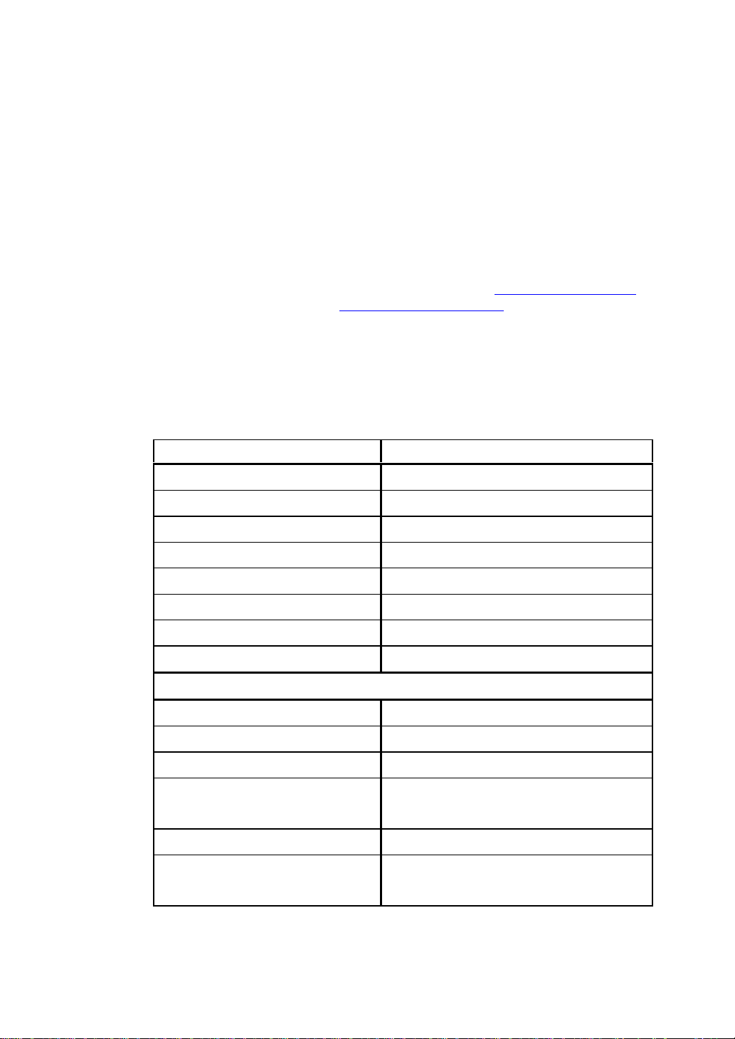
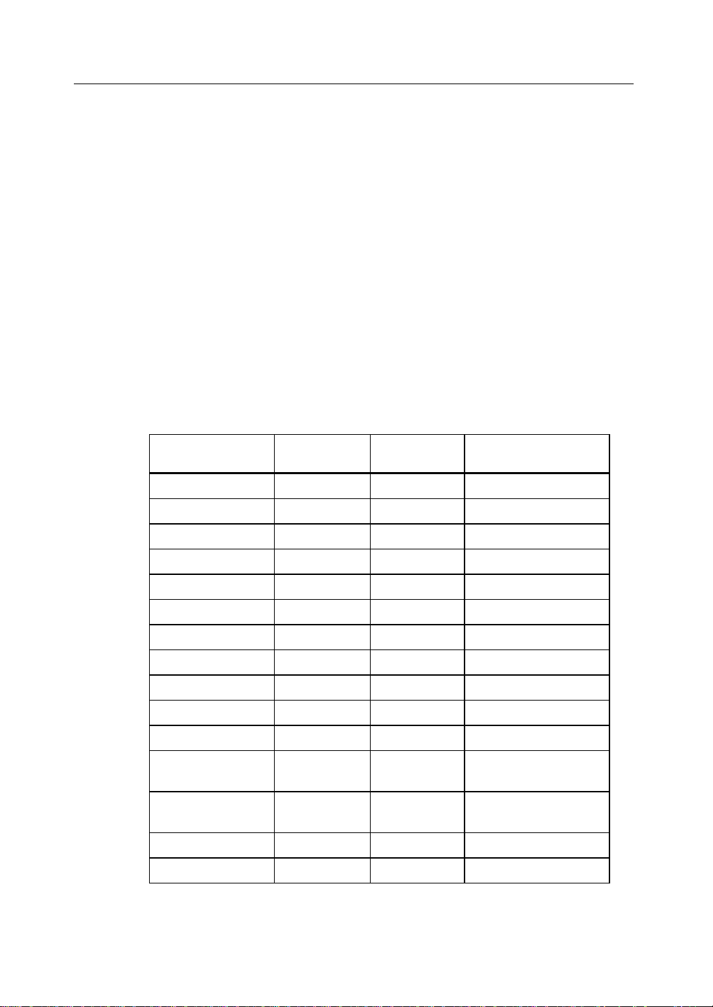
MegaRAID Problem Report Form
Complete this form before you call your Toshiba OEM Customer Service
Representative.
Table 1 MegaRAID Problem Report Form
Customer Information MegaRAID Information
Name Today’s Date
Company Date of Purchase
Address Invoice Number
City/State Serial Number
Country
Email address Cache Memory
Phone Firmware Version
Fax BIOS Version
System Information
Motherboard: BIOS manufacturer:
Operating System: BIOS Date:
Op. Sys. Ver.: Video Adapter:
MegaRAID
Driver Ver.:
Network Card: System Memory:
Other disk controllers
Installed:
CPU Type/Speed:
Other adapter cards
Installed:
Page 5
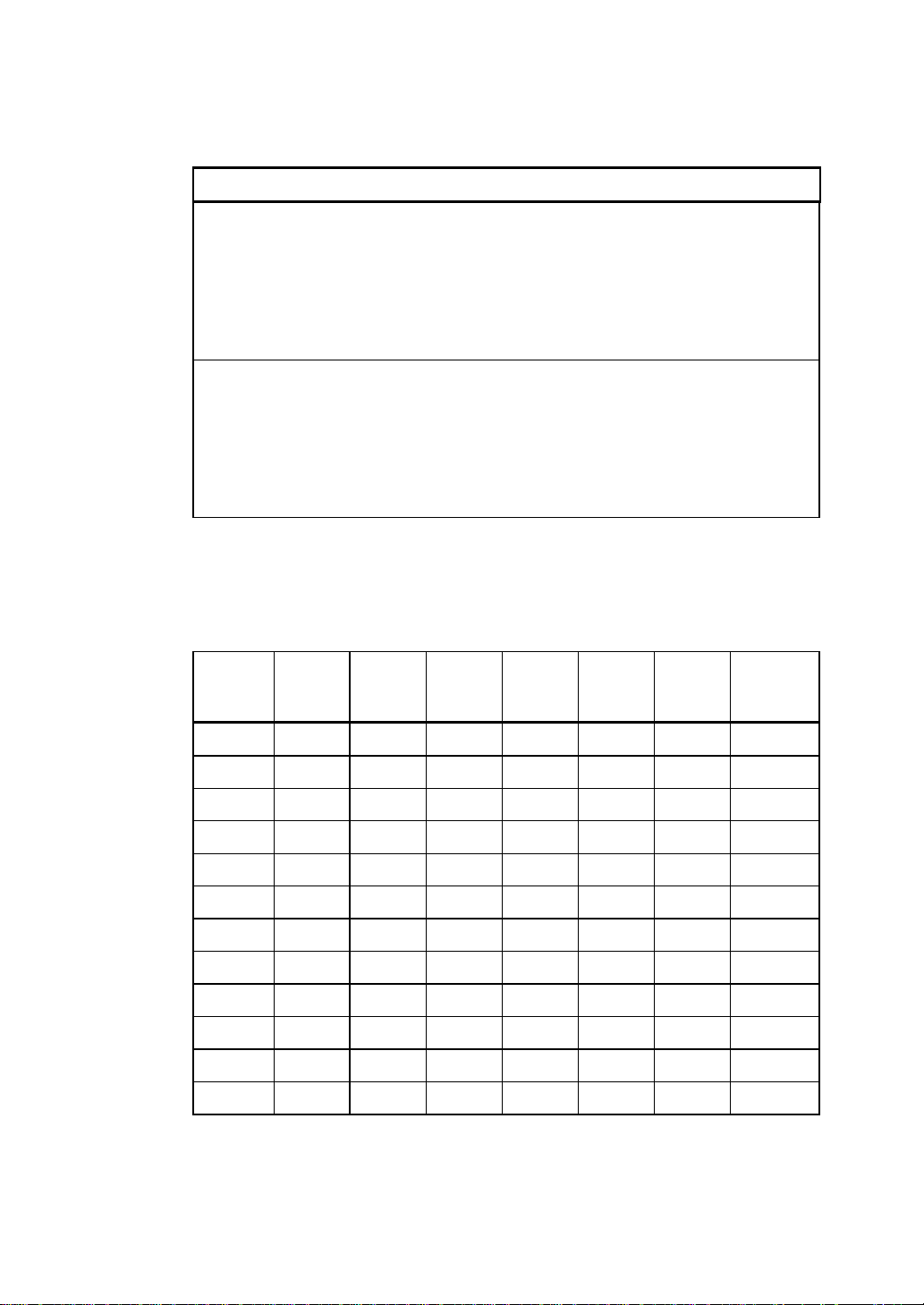
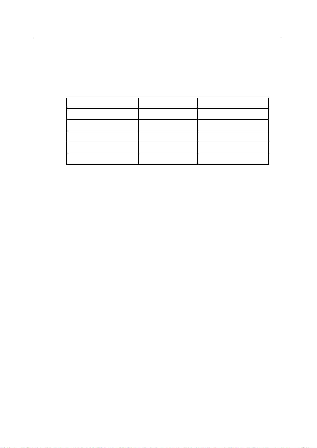
Table 1 MegaRAID Problem Report Form (Continued)
System Information
Description of problem:
Steps necessary to re-create problem:
1.
2.
3.
4.
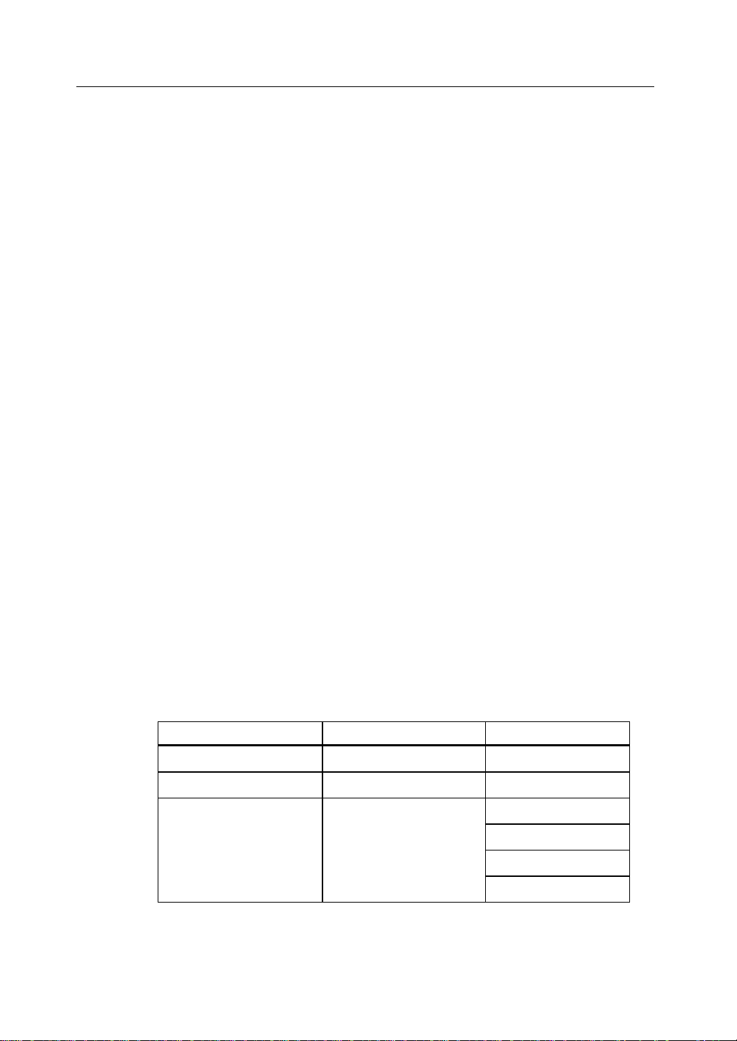
Logical Drive Configuration
Use this form to record the configuration details for your logical drives.
v
Logical
Drive
LD0
LD1
LD2
LD3
LD4
LD5
LD6
LD7
LD8
LD9
LD10
LD11
RAID
Level
Table 2 Logical Drive Configuration
Stripe
Size
Logical
Drive
Size
Cache
Policy
Read
Policy
Write
Policy
# of
Physical
Drives
Page 6

vi
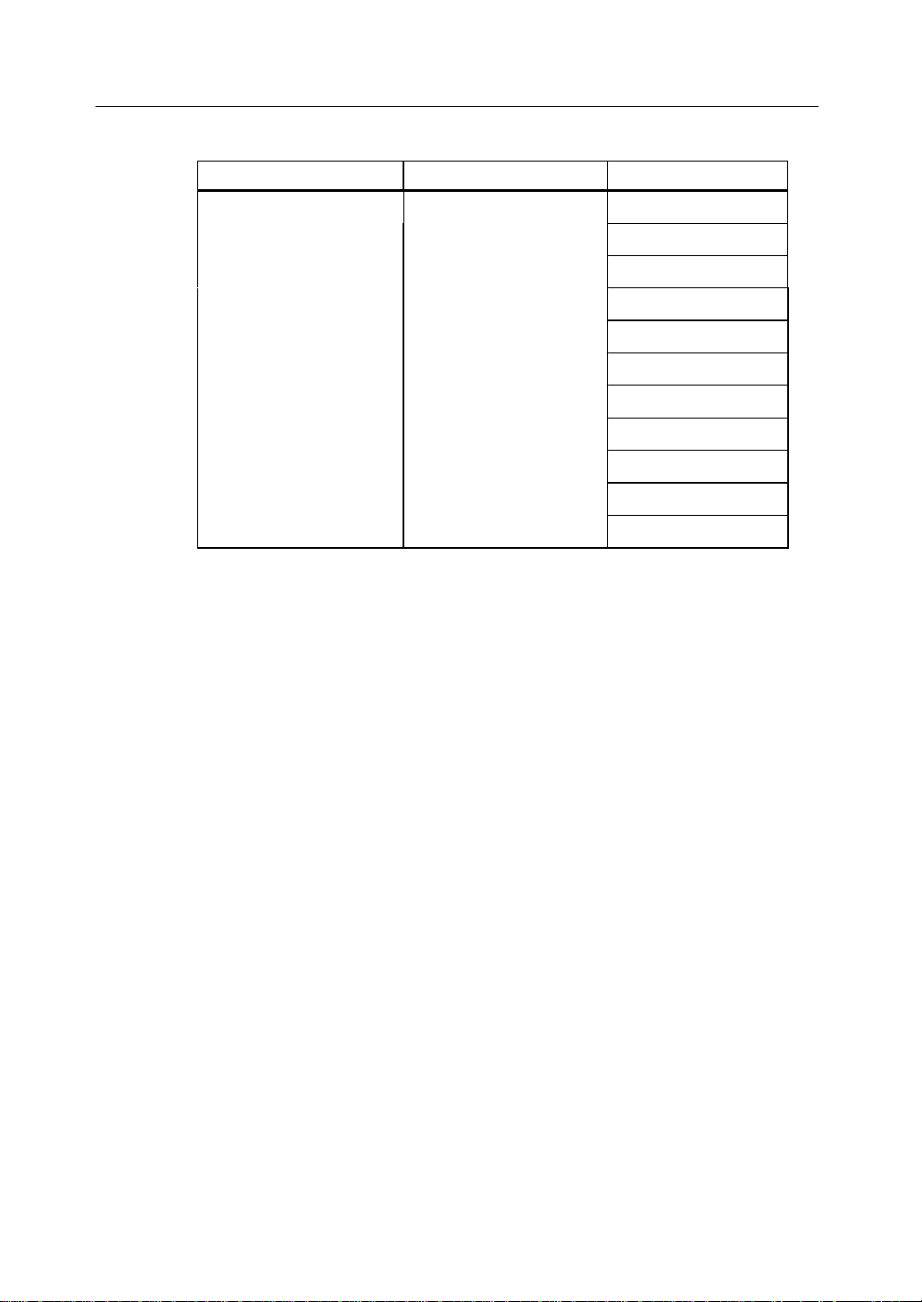
Table 2 Logical Drive Configuratio n ( C ontinued)
Logical
Drive
LD12
LD13
LD14
LD15
LD16
LD17
LD18
LD19
LD20
LD21
LD22
LD23
LD24
LD25
RAID
Level
Stripe
Size
Logical
Drive
Size
Cache
Policy
Read
Policy
Write
Policy
# of
Physical
Drives
LD26
LD27
LD28
LD29
LD30
LD31
LD32
LD33
LD34
LD35
LD36
LD37
LD38
LD39
Page 7

Physical Device Layout
Use this form to record the physical device layout.
Target ID
Device Type
Logical Drive Number/ Drive Number
Manufacturer/Model Number
Firmware level
Target ID
Device Type
Logical Drive Number/ Drive Number
Manufacturer/Model Number
vii
Table 3 Physical Drive Layout
Channel 1
Firmware level
Target ID
Device Type
Logical Drive Number/ Drive Number
Manufacturer/Model Number
Firmware level
Target ID
Device Type
Logical Drive Number/ Drive Number
Manufacturer/Model Number
Firmware level
Target ID
Device Type
Logical Drive Number/ Drive Number
Manufacturer/Model Number
Firmware level
Page 8

viii
Table 3 Physical Drive Layout (Continued)
Channel 1
Target ID
Device Type
Logical Drive Number/ Drive Number
Manufacturer/Model Number
Firmware level
Target ID
Device Type
Logical Drive Number/ Drive Number
Manufacturer/Model Number
Firmware level
Target ID
Device Type
Logical Drive Number/ Drive Number
Manufacturer/Model Number
Firmware level
Target ID
Device Type
Logical Drive Number/ Drive Number
Manufacturer/Model Number
Firmware level
Target ID
Device Type
Logical Drive Number/ Drive Number
Manufacturer/Model Number
Firmware level
Target ID
Device Type
Logical Drive Number/ Drive Number
Manufacturer/Model Number
Firmware level
Page 9

Table 3 Physical Drive Layout (Continued)
Target ID
Device Type
Logical Drive Number/ Drive Number
Manufacturer/Model Number
Firmware level
Target ID
Device Type
Logical Drive Number/ Drive Number
Manufacturer/Model Number
Firmware level
Target ID
Device Type
ix
Channel 1
Logical Drive Number/ Drive Number
Manufacturer/Model Number
Firmware level
Target ID
Device Type
Logical Drive Number/ Drive Number
Manufacturer/Model Number
Firmware level
Page 10

x
Disclaimer
This manual describes the operation of the Toshiba RAID Controller Kit-G Disk Array
Controller. Although efforts have been made to assure the accuracy of the information
contained here, Toshiba expressly disclaims liability for any error in this information,
and for damages, whether direct, indirect, special, exemplary, consequential or
otherwise, that may result from such error, including but not limited to the loss of profits
resulting from the use or misuse of the manual or information contained therein (even if
Toshiba has been advised of the possibility of such damages). Any questions or
comments regarding this document or its contents should be addressed to Toshiba at the
address shown on the cover.
Toshiba provides this publication “as is” without warranty of any kind, either expressed
or implied, including, but not limited to, the implied warranties of merchantability or
fitness for a specific purpose.
Some states do not allow disclaimer of express or implied warranties or the limitation or
exclusion of liability for indirect, special, exemplary, incidental or consequential
damages in certain transactions; therefore, this statement may not apply to you. Also,
you may have other rights which vary from jurisdiction to jurisdiction.
This publication could include technical inaccuracies or typographical errors. Changes
are periodically made to the information herein; these changes will be incorporated in
new editions of the publication. Toshiba may make improvements and/or revisions in
the product(s) and/or the program(s) described in this publication at any time.
Requests for technical information about Toshiba products should be made to your
Toshiba authorized reseller or marketing representative.
Page 11

Copyright
xi
© Copyright 2002 Toshiba Corporation
All rights reserved.
Toshiba Corporation
6145-D Northbelt Parkway
Norcross, GA 30071
This publication contains proprietary information which is protected by copyright. No
part of this publication can be reproduced, transcribed, stored in a retrieval system,
translated into any language or computer language, or transmitted in any form
whatsoever without the prior written consent of the publisher, T oshiba Corporation.
Toshiba acknowledges the following trademarks.
Intel is a registered trademark of Intel Corporation.
Sytos 300 is a registered trademark of Sytron Corporation.
MS-DOS, and Microsoft are registered tradem arks of Microsoft Corporation , Win dows
95, Microsoft Windows are trademarks of Microsoft Corporation.
SCO, UnixWare, and Unix are registered trademarks of the Santa Cruz Operation. Inc.
IBM, AT, VGA, PS/2, and OS/2 are registered trademarks and XT and CGA are
trademarks of International Business Machines Corporation.
NEC is a registered trademark of Nippon Electric Corporation.
Sony is a registered trademark of Sony Corporation.
Toshiba is a registered trademark of Toshiba America Corporation.
Archive and Python are registered trademarks of Archive Corporation.
Quantum is a registered trademark of Quantum Corporation.
Seagate is a registered trademark of Seagate Corporation.
SyQuest is a trademark of SyQuest Corporation.
ASPI is a registered trademark of Adaptec, Inc.
Panasonic is a registered trademark of Panasonic Corporation.
Hewlett-Packard is a registered trademark of Hewlett-Packard Corporation.
Amphenol is a trademark of Amphenol Corporation.
Siemens is a registered trademark of Siemens Corporation.
AMP is a trademark of AMP Corporation.
Revision History
8/16/02 Initial release.
Page 12

xii
Toshiba Confidential
This document contains proprietary information of Toshiba Corporation. The
information contained herein is not to be used by or disclosed to third parties without
the express written permission of an officer of Toshiba Corporation.
Document DB15-000255-00, First Edition (August 2002)
This document describes the configuration software for Toshiba Corporation's
MegaRAID controllers and will remain the official reference source for all
revisions/releases of these products until rescinded by an update.
Toshiba Corporation reserves the right to make changes to any products herein at any
time without notice. Toshiba does not assume any responsibilit y or liability arising o ut
of the application or use of any product described herein, except as expressly agreed to
in writing by Toshiba; nor does th e purch ase or us e of a produ ct f rom Toshiba con vey a
license under any patent rights, copyrights, trademark rights, or any other of the
intellectual property rights of Toshiba or third parties.
Copyright © 1998-2002 by Toshiba Corporation. All rights reserved.
TRADEMARK ACKNOWLEDGMENT
The Toshiba logo design and MegaRAID are trademarks of Toshiba Corporation.
Novell is registered trademarks of Novell Corporation. Microsoft and Windows are
registered trademarks of Microsoft Corporation. All other brand and product names
may be trademarks of their respective companies.
CD
To download the latest drivers and documentation, and receive product literature, visit
us at http://www.Toshiba.com.
For a current list of our dis tribut ors, sal es off ices, and desi gn resou rce cente rs, view our
web page located at
http://www.Toshiba.com/contacts/na_salesoffices.htmlPre.
Page 13
FCC Regulatory Statement
This device complies with Part 15 of the FCC Rules. Operation is subject to the
following two conditions: (1) this device may not cause harmful interference, and (2)
this device must accept any interference received, in cluding interference that may cause
undesired operation.
WARNING: Changes or modifications to this unit not expressly approved by
the party responsible for compliance could void the user's authority to operate
the equipment.
NOTE: This equipment has been tested and found to comply with the limits for
a Class B digital device, pursuant to Part 15 of the FCC Rules. These limits are
designed to provide reasonable protection against harmful interference in a
residential installation. This equipment generates, uses and can radiate rad io
frequency energy and, if not installed and used in accordance with the
instructions, may cause harmful interference to radio communications.
However, there is no guarantee that interference will not occur in a specific
installation. If this equipment does cause harmful interference to radio or
television reception, which can be determined by turning the equipment off
and on, try to correct the interference by one or more of the following
measures:
xiii
1. Reorient or relocate the receiving antenna.
2. Increase the separation between the equipment and the receiver.
3. Connect the equipment into an outlet on a circuit different from that to
which the receiver is connected.
4. Consult the dealer or an experienced radio/TV technician for help.
Shielded interface cables must be used with this product to ensure compliance
with the Class B FCC limits.
Toshiba RAID Controller Kit-G PCI RAID Controller
Model Number: Series 520
FCC ID Number:
DISCLAIMER
TOSHIBA certifies only that this product will work correctly when this product is
used with the same jumper settings, the same system confi guration, the same
memory module parts, and the same peripherals that were tested by TOSHIBA
with this product. The complete list of tested jumper settings, system
configurations, peripheral devices, and memory modules are documented in the
TOSHIBA Compatibility Report for this prod uct. Call your TOSHIBA sales
representative for a copy of the Compatibility Report for this product.
Page 14

xiv
Table of Contents
Preface iii
Symbols Used in This Guide xvii
Chapter 1 Overview 3
Overview 3
Chapter 2 Introduction to RAID 9
RAID Controller Kit-G – Host-Based RAID Solution 10
RAID Overview 11
Chapter 3 RAID Levels 23
RAID Levels 23
Chapter 4 Features 33
Operating System Software Drivers 36
Chapter 5 Configuring RAID Controller Kit-G 45
Configuring SCSI Physical Drives 45
Configuri ng Lo gi ca l Dri ve s 54
Chapter 6 Hardware Installation 59
Installation Steps 60
Chapter 7 Troubleshooting 79
Troubleshooting 79
Chapter 8 Introduction 89
In this Manual 90
Page 15

Chapter 9 MegaRAID BIOS Configuration Utility 95
In this Chapter 95
Starting the MegaRAID BIOS Configura tion Utility 95
Configuri ng Arrays and Logical Drives 105
Initializing Logical Drives 115
Rebuilding Failed Disk Drives 117
Using a Pre-loaded SCSI Drive "As-is" 118
Exiting MegaRAID Configuration Utility 119
MegaRAID Configuration On Disk 119
xv
Chapter 10
Features 123
Starting the WebBIOS Utility on the Host Computer 124
WebBIOS Toolbar Icons 126
Adapter Properties 127
Scan Devices 129
SCSI Channel Properties 129
Logical Drives 130
Physical View/Logical View 138
Configuration Mismatch 139
WebBIOS Configuration Utility 123
Chapter 11 Installing Power Console Plus 143
Features 143
Installing on a and Workstation 145
Installing a Toshiba SNMP Agent 149
MegaRAID Service Monitor 150
De-registering and Re-registering under Power Console Plus 151
Chapter 12 Running Power Console Plus 155
Starting Power Console Plus 155
Power Console Plus Screen Layout 156
Power Console Plus Toolbox Icons 157
Power Console Plus Menus 161
Configuration Menu 161
Page 16

xvi
Adapter Menu 164
Physical Drive Menu 167
Logical Drive Menu 169
Progress Menu 172
Securing Power Console Plus under Windows 2000 173
Chapter 13 Configuring Arrays and Logical Drives
with Power Console Plus 177
Step 1 Start Power Console Plus 177
Step 2 Choose an Adapter 179
Step 3 Run the Wizard 179
Step 4 Save Configuration and Initialize 184
Assigning Hot Spares 185
Chapter 14 Virtual Sizing and Online Capacity
Expansion 189
Location and Enabling 189
Theory of Operation 189
MegaRAID Drive Characteristics 190
Deleting Logical Drives 190
Adding Capacity to an Array 190
Appendix A SCSI Cables and Connectors 195
SCSI Cables and Connectors 195
Appendix B Audible Warnings 207
Audible Warnings 207
Appendix C MegaRAID Service Monitor 211
Power Console Plus Internal Messages 211
MegaRAID Service Monitor 212
Event Types 212
Page 17
Symbols Used in This Guide
Notational Conventions
Icons
The following icons are used in this guide to highlight helpful or educational
information:
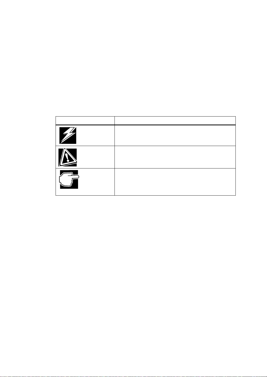
Label Meaning
xvii
DANGER
CAUTION
NOTE
*1: Bodily harm means a personal injury, burn, or electric shock, which is treated
without staying in or regularly going to hospital.
*2: Physical damage means actual damage to the building, furnishings or animals.
Indicates an imminent danger of causing death or severe
injury unless the instruction is observed.
(*1)
Indicates a risk of causing bodily harm
damage
Highlights the instructions you should observe to
prevent data loss, faults, or performance degradation
and technical information you should know about
specifications or functions.
(*2)
unless the instruction is observed.
or physical
Page 18

xviii
Page 19

Chapter 1
Overview ...............................................................................3
Page 20

Page 21

Overview
The RAID Controller Kit-G is a high-performance, intelligent PCI-to-SCSI host
adapter with RAID control capabilities. The RAID Controller Kit-G provides reliability,
high performance, and fault-tol erant disk subsystem management.
The RAID Controller Kit-G is part of the Toshiba Intel GC80302-based MegaRAID
controller family. The RAID Controller Kit-G is an entry level- to mid-range RAID
controller solution. RAID Controller Kit-G offers a cost-effective way to implement
RAID in a server.
The RAID Controller Kit-G has a Ultra320 and Wide SCSI channel supporting data
transfer rates up to 320 megabytes per second (MB/s) per channel. The SCSI channel
supports up to fifteen non-Ultra SCSI devices. The RAID Controller Kit-G includes
MegaRAID features and performance.
Features
RAID Controller Kit-G features include:
• A high-performance input/output (I/O) migration path while preserving existing
PCI-SCSI software
• SCSI data transfers up to 320 MB/s
• Synchronous operation on a wide low-voltage differential (LVD) SCSI bus
• Support for up to 15 LVD SCSI devices on the wide bus
• An Intel® GC30302 chip that performs RAID calculations and routing
• Support for 32 or 64 MB of SDRAM on-board cache memory used for read and
write-back caching, and RAID 5 parity generation.
Overview
Overview
3
SCSI Channel
The RAID Controller Kit-G upgrade card includes one Ultra3 SCSI channel. The
channel is powered by a Toshiba Corporation 53C1020 Ultra320 SCSI processor.
NVRAM and Flash ROM
A 32 KB x 8 NVRAM stores RAID system configuration information. The RAID
Controller Kit-G firmware is stored in flash ROM for easy upgrade.
Page 22
4
Overview
Overview
SCSI Connectors
RAID Controller Kit-G has one very high-density 68-pin external connector for
external storage subsystem, and one high-density 68-pin internal connector.
Single Ended and Differential SCSI Buses
The SCSI standard defines two electrical buses:
• A single-ended bus
• Low-voltage differential bus
Maximum Cable Length for SCSI Standards
Table 1.1 contains the maximum cable length that you can use depending on the SCSI
speeds, and type of device.
Table 1.1 Maximum Cable Length for SCSI Standards
Standard Single ended Low-voltage
Differential
Ultra SCSI 1.5 m 12 m 7
Ultra SCSI 3 m 12 m 3
Wide Ultra SCSI 12 m 15
Wide Ultra SCSI 1.5 m 12 m 7
Wide Ultra SCSI 3 m 12 m 3
Ultra 2 SCSI 25 m 1
Ultra 2 SCSI 12 m 7
Wide Ultra 2 SCSI 25 m 1
Wide Ultra 2 SCSI 12 m 15
Ultra160 SCSI 25m 1
Ultra160 SCSI 12m 7
Wide Ultra160
SCSI
Wide Ultra160
SCSI
Ultra320 12m 15
25m 1
12m 15
Maximum Number of
Drives
Ultra320 20m 1
Page 23
SCSI Bus Widths and Maximum Throughput
Table 1.2 contains the SCSI bus widths, and maximum throughput, based on the SCSI
speeds.
Table 1.2 SCSI Bus Widths and Maximum Throughput
SCSI Standard SCSI Bus Width SCSI Throughput
Fast Wide SCSI 16 bits 20 MB/s
Wide Ultra SCSI 16 bits 40 MB/s
Wide Ultra 2 SCSI 16 bits 80 MB/s
Wide Ultra 160 SCSI 16 bits 160 MB/s
Ultra 320 SCSI 16 bits 320 MB/s
Documentation
The RAID Controller Kit-G documentation set includes:
• The RAID Controller Kit-G Hardware Guide
• The MegaRAI D Configuration Softwar e Guide
• The MegaRAID Operating System Driver Installation Guide
Overview
Overview
5
RAID Controller Kit-G Hardware Guide
The hardware guide for this board contains the RAID overview, RAID planning, and
RAID system configuration information you will need first. Read the RAID Controller
Kit-G Hardware Guide first.
MegaRAID Configuration Software Guide
This manual describes the software configuration utilities that you can use to configure
and modify RAID systems.
MegaRAID Operating System Driver Installation Guide
This manual provides detailed information about ins talling the RAI D Controller Kit -G
operating system drivers.
Page 24

6
Overview
Overview
Page 25

Chapter 2
Introduction to RAID .............................................................9
RAID Controller Kit-G – Host-Based RAID Solution...............................10
RAID Overview ..........................................................................................11
Page 26

Page 27
Introduction to RAID
Introduction to RAID
Introduction to RAID
RAID is an array of multiple independent hard disk drives that provide high
performance and fault tolerance. A RAID disk subsystem improves I/O performance
over a computer using only a single drive. The RAID array appears to the host computer
as a single storage unit or as multiple logical units. I/O is expedited because several
disks can be accessed simultaneously. RAID systems improve data storage reliability
and fault tolerance compared to single-drive computers. Data loss because of a disk
drive failure can be recovered by reconstructing missing data from the remaining data
and parity drives.
RAID Benefits
RAID has gained popularity becaus e it improves I/O perf ormance and increases storage
subsystem reliability. RAID provides data security through fault tolerance and
redundant da ta stora ge. The RAID Co ntroller Kit-G manageme nt soft ware configur es
and monitors RAID disk arrays.
Improved I/O
9
Although disk drive capabilities have improved drastically, actual performance has
been improved only three to four times in the last decade. Computing performance has
been improved over 50 times during the same time period.
Increased Reliability
The electro-mechanical components of a disk subsystem operate more slowly, require
more power, and generate more noise and vibration than electronic devices. These
factors reduce the reliability of data stored on disks.
In This Chapte r
Table 2.1 lists the topics discussed in this chapter.
Major Topic Subtopic Turn to
Host-based solution page 10
RAID overview page 11
Table 2.1 Topics in this Chapter
Physical array page 11
Logical drive p age 11
Fault tolerance page 12
Consistency check page 11
Page 28
10
RAID Controller Kit-G – Host-Based RAID Solution
Introduction to RAID
Table 2.1 Topics in this Chapter (Cont inued)
Major Topic Subtopic Turn to
Disk striping page 13
Disk mirroring page 14
Disk spanning page 15
Parity page 16
Hot spares page 16
Hot swap page 16
Disk rebuilds page 17
Logical drive states page 18
SCSI drive states page 18
Disk array types page 19
Enclosure mana ge me nt page 19
RAID Controller Kit-G – Host-Based RAID
Solution
RAID products are either:
• Host-based, or
• External
The RAID Controller Kit-G controller is a h ost - based RAID solution. RAID Controller
Kit-G is a PCI adapter card that is installed in any available PCI expansion slot in a host
system.
Host-Based
A host-based RAID product puts all of the RAID intelligence on an adapter card that is
installed in a network server. A host-based RAID product provides the best
performance. RAID Controller Kit-G is part of the file server, so it can transmit data
directly across the computer’s buses at data transfer speeds up to 532 MB/s.
The available sequential data transfer rate is determined by the following factors:
• The sustained data transfer rate on the motherboard PCI bus
• The sustained data transfer rate on the GC80302 PCI-to-PCI bridge
• The sustained data transfer rate of the SCSI controller
• The sustained data transfer rate of the SCSI devices
• The number of SCSI channels
• The number of SCSI disk drives
Host-based solutions must provide operating system-specific drivers.
Page 29

SCSI-to-SCSI External
A SCSI-to-SCSI External RAID product puts the RAID intelligence inside the RAID
chassis and uses a plain SCSI Host Adapter installed in the network server. The data
transfer rate is limited to the bandwidth of the SCSI channel. A SCSI-to-SCSI R AID
product that has two wide SCSI channels operating at speeds up to 320 MB/s must
squeeze the data into a single w ide SCSI (320 MB/s) ch annel back to th e host computer.
In SCSI-to-SCSI RAID produ ct s, th e hard drive subsystem uses on ly a s ing le S CSI ID,
which allows you to connect multiple drive subsystems to a single SCSI controller.
RAID Overview
RAID is a collection of specifications that describe a system for ensuring the reliability
and stability of data stored on large disk subsystems. A RAID system can be
implemented in a number of different versions (or RAID Levels). RAID Controller
Kit-G supports standard RAID levels 0, 1 and 5, and RAID levels 10 and 50, special
RAID versions supported by RAID Controller Kit-G.
Physical Array
RAID Overview
Introduction to RAID
11
A RAID array is a collection of physical disk drives governed by the RAID
management software. A RAID array appears to the host computer as one or more
logical drives.
Logical Drive
A logical drive is a partition in a physical array of disks that is made up o f contiguous
data segments on the physical disks . A logical drive can consist of any of the following:
• An entire physical array
• More than one entire physical array
• A part of an array
• Parts of more than one array
• A combination of any two of the above conditions
Consistency Check
In RAID, check consistency verifies the correctness of redundant data in an array. For
example, in a system with dedicated pa rity , ch ecki ng consis tency means computing the
parity of the data drives and com paring the results to the contents of the dedicated parity
drive.
Page 30

12
RAID Overview
Introduction to RAID
Fault Tolerance
Fault tolerance is achieved t hrough co oling fan s, po wer supplies, and the abilit y to hot
swap drives. RAID Controller Kit-G provides hot swapping through the hot spare
feature. A hot spare drive is an unused online available drive that RAID Controller
Kit-G instantly plugs into the system when an active drive fails.
After the hot spare is automatically moved into the RAID subsystem, the failed drive is
automatically rebuilt. The RAID disk array continues to handle request while the
rebuild occurs.
Page 31

Disk Striping
Disk striping writes data across multiple disk drives instead of just one disk drive. Disk
striping involves partitioning each drive storage space in to stripe s tha t can var y in size
from 2 KB to 128 KB. These stripes are interleaved in a repeated sequential manner.
The combined storage space is composed of stripes from each drive. RAID Controller
Kit-G supports stripe sizes of 2 KB, 4 KB, 8 KB, 16 KB, 32 KB, 64 KB, or 128 KB.
For example, in a four-disk system using only disk striping (as in RAID level 0),
segment 1 is written to disk 1, segment 2 is written to disk 2, and so o n. Disk stripin g
enhances performance because multiple drives are accessed simultaneously; but disk
striping does not provide data redundancy.
RAID Overview
Introduction to RAID
13
Stripe Width
Stripe width is a measure of the number of disks involved in an array where striping is
implemented. For example, a four-disk array with disk striping has a stripe width of
four.
Stripe Size
The stripe size is the length of the interleaved data segments that RAID Controller
Kit-G writes across multiple drives. RAID Controller Kit-G supports stripe sizes of 2
KB, 4 KB, 8 KB, 16 KB, 32 KB, 64 KB, or 128 KB.
Page 32

14
RAID Overview
Introduction to RAID
Disk Mirroring
With mirroring (used in RAID 1), data written to one disk drive is simultaneously
written to another disk drive. If one disk drive fails, the contents of the other disk drive
can be used to run the sy stem and reconstruct the failed drive. The primary advantage of
disk mirroring is that it provides 100% data redundancy. Since the contents of the disk
drive are completely written to a second drive, it does not matter if one of the drives
fails. Both drives contain the same data at all times. Either drive can act as the
operational drive.
Disk mirroring provides 100% redundancy, but is expensive because each drive in the
system must be duplicated.
Page 33

Disk Spanning
Disk spanning allows multiple disk drives to function like one big drive. Spanning
overcomes lack of disk space and simplifies storage management by combining
existing resources or adding relativ ely inex pensive resources. For example, four 60 GB
disk drives can be combined to appear to the operating system as one single 240 GB
drive.
Spanning alone does not provide reliability or performance enhancements. Spanned
logical drives must have the same stripe size and must be contiguous. In the following
graphic, RAID 1 array is turned into a RAID 10 array.
RAID Overview
Introduction to RAID
15
Spanning for RAID 10, or RAID 50
Table 2.2 describes spanning for RAID 10, and RAID 50.
Table 2.2 Spanning for RAID 10, or RAID 50
Level Description
10 Configure RAID 10 by spann ing tw o contiguous RA ID 1 l ogical dri ves . The
RAID 1 logical drives must have the same stripe size.
50 Configure RAID 50 by spann ing tw o contiguous RA ID 5 l ogical dri ves . The
RAID 5 logical drives must have the same stripe size.
NOTE: Spanning two contiguous RAID 0 logical drives does not produce a
new RAID level or add fault tolerance. It does increase the size of the logical
volume and improves performance by doubling the number of spindles.
Page 34

16
Parity
RAID Overview
Introduction to RAID
Parity generates a set of redundancy data from two or more parent data sets. The
redundancy data can be used to reconstruct one of the parent data sets. Parity data does
not fully duplicate the parent data sets. In RAID, this method is applied to entire drives
or stripes across all disk drives in an array.
Table 2.3 describes distributed parity, which is used in RAID 5.
Table 2.3 Distributed Parity
Type Description
Distributed Parity The parity data is distributed across all drives in the
system.
If a single disk drive fails, it can be rebuilt from the parity and the data on the remaining
drives.
RAID 5 combines distributed parity with disk striping. Parity provides redundancy for
one drive failure without duplicating the contents of entire disk drives, but parity
generation can slow the write process.
Hot Spares
Hot Swap
A hot spare is an extra, unused disk drive that is part of the disk subsystem. It is usually
in standby mode, ready for service if a drive fails. Hot spares permit you to replace
failed drives without system shutdown or user intervention.
RAID Controller Kit-G implements automatic and transparent rebuilds using hot spare
drives, providing a high degree of fault tolerance and zero downtime. The RAID
Controller Kit -G RAID M a na ge ment software allo ws you t o spe cify physical dri ve s as
hot spares. When a hot spare is needed, the RAID Controller Kit-G controller assigns
the hot spare that has a capacity closest to and at leas t as great as that of the failed driv e
to take the place of the failed drive.
NOTE: Hot spares are employed only in arrays with redundancy, for example,
RAID levels 1, 5, 10, and 50.
A hot spare connected to a specific RAID Controller Kit-G controller can be
used only to rebuild a drive that is connected to the same controller.
A hot swap is the manual replacement of a defective physical disk unit while the
computer is still running. When a new drive has been installed, you must issue a
command to rebuild the drive.
Page 35

Disk Rebuild
You rebuild a disk drive by recreating the data that had been stored on the drive before
the drive failed. Rebuilding can be done only in arrays with data redundancy such as
RAID level 1, 5, 10, and 50.
Standby (warm spare) rebuild is employed in a mirrored (RAID 1) system. If a disk
drive fails, an identical drive is immediately available. The primary data source disk
drive is the original disk drive.
A hot spare can be used to rebuild disk drives in RAID 1, 5, 10, or 50 systems. If a hot
spare is not available, the failed disk drive must be replaced with a new disk drive so
that the data on the failed drive can be rebuilt.
The RAID Controller Kit-G controller automatically and transparently rebuilds failed
drives with user-definable rebuild rates. If a hot spare is available, the rebuild starts
automatically when a drive fails. RAID Controller Kit-G automatically restarts the
system and the rebuild if the system goes down during a rebuild.
Rebuild Rate
The rebuild rate is the fraction of the compute cycles dedicated to rebuilding failed
drives. A rebuild rate of 100 percent m eans the sys tem is totally dedicated t o rebuil ding
the failed drive.
RAID Overview
Introduction to RAID
17
The RAID Controller Kit-G rebuild rate can be configured between 0% and 100%. At
0%, the rebuild is only done if the system is not doing anything else. At 100%, the
rebuild has a higher priority than any other system activity.
Page 36

18
RAID Overview
Introduction to RAID
Logical Drive States
Table 2.4 describes the possible states for logical drives.
State Description
Optimal The drive operating condition is good. All configured drives
Degraded The drive operating condition is not o ptimal. One of the
Failed The drive has failed.
Offline The drive is not available to RAID Controller Kit-G.
SCSI Drive States
Table 2.5 describes the states that a SCSI hard drive can be in.
State Description
Table 2.4 Logical Drive States
are online.
configured drives has failed or is offline.
Table 2.5 SCSI Drive States
Online
(ONLIN)
Ready
(READY)
Hot Spare
(HOTSP)
Fail
(FAIL)
Rebuild
(REB)
The drive is functioning normally and is a part of a configured
logical drive.
The drive is functioning normally but is not part of a
configured logical drive and is not designated as a hot spare.
The drive is powered up and ready for use as a spare in case
an online drive fails.
A fault has occurred in the drive placing it out of service.
The drive is being rebuilt with data from a failed drive.
Page 37

Disk Array Types
Table 2.6 describes the RAID disk array types.
Type Description
Software-Based The array is managed by software running in a host computer
SCSI-to-SCSI The array controller resides outside of the host computer and
Bus-Based The array controller resides on the bus (for example, a PCI or
RAID Overview
Introduction to RAID
Table 2.6 Disk Array Types
using the host CPU bandwidth. The disadvantages asso ciated
with this method are the load on the host CPU and the need for
different software for each operating system.
communicates with the host through a SCSI adapter in the host.
The array management software runs in the controller. It is
transparent to the host and independent of the host operating
system. The disadvantage is the limited data transfer rate of the
SCSI channel between the SCSI adapter and th e array con troller.
EISA bus) in the host computer and has its own CPU to generate
the parity and handle other RAID functi ons. A bus-based
controller can transfer data at the speed of the host bus (PCI,
ISA, EISA, VL-Bus) but is limited to the bus it is designed for.
RAID Controller Kit-G resides on a PCI bus, which can handle
data transfer at up to 132 MB/s. With RAID Controller Kit-G,
the channel can handle data transfer rates up to 320 MB/s per
SCSI channel.
19
Enclosure Management
Enclosure ma nagement is the inte ll i ge nt mo nit or i ng o f t he d i s k sub s yst e m b y software
and/or hardware.
The disk subsystem can be part of the host computer or separate from it. Enclosure
management helps you stay informed of events in the disk subsystem, such as a drive or
power supply failure. Enclosure management increases the fault tolerance of the disk
subsystem.
Page 38

20
RAID Overview
Introduction to RAID
Page 39

Chapter 3
RAID Levels........................................................................23
Page 40

22
System Configuration Setup
System Configuration Setup
System Configuration SetupSystem Configuration Setup
Setup
Page 41

RAID Levels
RAID Controller Kit-G supports RA ID levels 0, 1, 5, 10, an d 50. This ch apter descri bes
the RAID levels, and factors to consider when you select a level.
Table 3.1 RAID Levels
RAID Level Type Turn to
0 Standard page 25
1 Standard page 26
5 Standard page 27
10 RAID Controller Kit-G only page 28
50 RAID Controller Kit-G only page 29
Selecting a RAID Level
RAID Levels
RAID Levels
23
To ensure the best performance, you should select the optimal RAID level when you
create a system drive. The optim al RAID level f or your disk array depen ds on a num ber
of factors:
• the number of drives in the disk array
• the capacity of the drives in the array
• the need for data redundancy
• the disk performance requirements
Page 42

24
RAID Levels
RAID Levels
Table 3.2 describes the factors you need to consider when selecting a RAID level.
Table 3.2 Factors for Selecting RAID Levels
Level Description and
Use
0 Data divided in
blocks and
distributed
sequentially
(pure strip i ng).
Use for noncritical data that
requires high
performance.
1 Data duplicated
on another disk
(mirroring). Use
for readintensive faulttolerant systems.
5 Disk striping and
parity data across
all drives. Use for
high read vo lume
but low write
volume, such as
transaction
processing.
Pros Cons Maximum
Number of
Physical
Drives
High data
throughput
for large
files
100% data
redundancy
Achieves
data
redundancy
at low cost
No fault
tolerance.
All data lost
if any drive
fails.
Doubles
disk space.
Reduced
performance
during
rebuilds.
Performance
not as good
as RAID 1
One to 15 No
Two Yes
Three to 15 Yes
Fault
Tolerant
10 Data striping and
mirrored drives.
50 Disk striping and
parity data across
all drives.
NOTE: The maximum number of physical drives supported by the SCSI
320-1 controller is 15.
High data
transfers,
complete
redundancy
High data
transfers,
redundancy
More
complicated
More
complicated
Four to 14
(must be a
multiple of
two)
Six to 15 Yes
Yes
Page 43

RAID 0
RAID Levels
RAID Levels
RAID 0 provides disk striping across all drives in the RAID subsystem. RAID 0 does
not provide any data redundancy, but does offer the best performance of any RAID
level. RAID 0 breaks up data into smaller blocks and then writes a block to each drive in
the array. The size of each block is determined by the stripe size parameter, set during
the creation of the RAID set. RAID 0 offers high bandwi dth. By breaking up a large file
into smaller blocks, RAID Controller Kit-G can use several drives to read or write the
file faster. RAID 0 involves no parity calculations to complicate the write operation.
This makes RAID 0 ideal for applications that require high bandwidth but do not
require fault tolerance.
Uses RAID 0 provides high data th roughput, es pecially for l arge fi les. Any
environment that does not require fault tolerance.
Strong Points Provides increased data throughput for large files. No capacity loss
penalty for parity.
Weak Points Does not provide fault tolerance. All data lost if any drive fails.
Drives One to 15
The initiator takes one ID per channel. This leaves 15 IDs available
for one channel.
25
Segment 1
Segment 3
Segment 5
Segment 7
etc.
Segment 2
Segment 4
Segment 6
Segment 8
etc.
Page 44

26
RAID 1
RAID Levels
RAID Levels
In RAID 1, RAID Controller Kit-G duplicates all data from one drive to a second drive.
RAID 1 provides complete data redundancy, but at the cost of doubling the required
data storage capacity.
Uses Use RAID 1 for small databases or any other environment that
requires fault tolerance but small capacity.
Strong Points RAID 1 provides complete data redundancy. RAID 1 i s ideal f or an y
application that requires fault tolerance and minimal capacity.
Weak Points RAID 1 requires twice as many disk drives. Performance is impaired
during drive rebuilds.
Drives Two.
Page 45

RAID 5
RAID Levels
RAID Levels
RAID 5 includes disk striping at the byte level and parity. In RAID 5, the parity
information is written to several drives. RAID 5 is best suited for networks that perform
a lot of small I/O transactions simultaneously.
RAID 5 addresses the bottleneck issue for random I/O operatio ns. Since each drive
contains both data and parity numerous writes can take place concurrently. In addition,
robust caching algorithms and hardware based exclusive-or assist make RAID 5
performance exceptional in many different environments.
Uses RAID 5 provides high data throughput, especially for la rge f iles. Us e
RAID 5 for transaction processing applications because each drive
can read and write independently. If a drive fails, RAID Controller
Kit-G uses the parity drive to recreate all missing information. Use
also for office automation and online customer service that requires
fault tolerance. Use for any application that has high read request
rates ,but low write request rates.
Strong Points Provides data redundancy and good performance in most
environments.
Weak Points Disk drive performance will be reduced if a drive is being rebuilt.
Environments with few processes do not perform as well because th e
RAID overhead is not offset by the performance gains in handling
simultaneous p rocesses.
27
Drives Three to 15.
Page 46

28
RAID Levels
RAID Levels
RAID 10
RAID 10 is a com bination of RAID 0 and RAID 1. RAID 10 has m irrored driv es. RA ID
10 breaks up data into smaller blocks, and then stripes the blocks of data to each RAID
1 raid set. Each RAID 1 raid set then duplicates its data to its other drive. The size of
each block is determined by the stripe size param eter, which is s et during the creation of
the RAID set. RAID 10 can sustain one to four drive failures while maintaining data
integrity if each failed disk is in a different RAID 1 array.
Uses RAID 10 works best for data storage that must have 100%
redundancy of mirrored arrays and that also needs the enhanced I/O
performance of RAID 0 (striped arrays). RAID 10 works well for
medium-sized databases or any environment that requires a higher
degree of fault tolerance and moderate to medium capacity.
Strong Points RAID 10 provides both high data transfer rates and complete data
redundancy.
Weak Points RAID 10 requires twice as many drives as all other RAID levels
except RAID 1.
Drives Four to 14.
Page 47

RAID 50
RAID Levels
RAID Levels
RAID 50 provides the features of both RAID 0 and RAID 5. RAID 50 includes both
parity and disk striping across multiple drives. RAID 50 is best implemented on two
RAID 5 disk arrays with data striped across both disk arrays. RAID 50 breaks up data
into smaller blocks, and then stripes the blocks of data to each RAID 5 raid s et. RAID 5
breaks up data into smaller blocks, calculates parity by performing an exclusive-or on
the blocks, and then writes the blocks of data and parity to each drive in the array. The
size of each block is determined by the stripe size parameter, which is set during the
creation of the RAID set.
RAID 50 can sustain one to four drive failures while maintaining data integrity if each
failed disk is in a different RAID 5 array.
Uses RAID 50 works best when used with data that requires high
reliability, high request rates, and high data transfer and medium to
large capacity.
Strong Points RAID 50 provides high data throughput, data redundancy, and very
good performance.
Weak Points Requires 2 to 4 times as many parity drives as RAID 5.
Drives Six to 15
The initiator takes one ID per channel. This leaves 15 IDs available
for one channel.
29
Page 48

30
RAID Levels
RAID Levels
Page 49

Chapter 4
Features.................................................................................33
Operating System Software Drivers............................................................36
Page 50

Page 51

Features
MegaRAID is a family of high performance intelligent PCI-to-SCSI host adapters with
RAID control capabilities. RAID Controller Kit-G has a SCSI channel that supports
Ultra320 and Wide SCSI at data transfer rates up to 320 MB/s. The SCSI channel
supports up to 15 Wide devices and up to seven non-Wide devices.
In This Chapte r
Topics described in this chapter include:
• New features
• Configurati on features
• Hardware architecture features
• Array performance features
• RAID manage me nt fea t ur es
• Fault tolerance features
• Utility programs
• Software drivers
Features
Features
33
SMART Technology
The RAID Controller Kit-G self-monitoring analysis and reporting technology
(SMART) detects predictable drive failures. SMART monitors the internal
performance of all motors, heads, and drive electronics.
Configuration on Disk
Configuratio n on Disk (dr ive roaming) save s configuratio n information both in nonvolatile random access memory (NVRAM) on RAID Controller Kit-G and on the d isk
drives connected to RAID Controller Kit-G. If RAID Controller Kit-G is replaced, the
new RAID Controller Kit-G controller can detect the actual RAID configuration,
maintaining the integrity of the data on each drive, even if the drives have changed
channel and/or target ID.
Hardware Requirements
RAID Controller Kit-G can be installed in a computer with a motherboard that has 5
volt/3.3 volt PCI expansion slots. The computer must support PCI version 2.2 or later.
The computer should have a n Intel Pentiu m, Pentium P ro, or more p owerful CPU, a
floppy drive, a color monitor and VGA adapter card, a mouse, and a keyboard.
Page 52

34
Features
Features
Configuration Features
Table 4.1 contains the configuration features for the RAID Controller Kit-G board.
Specification Feature
RAID levels 0, 1, 5, 10, and 50
SCSI channels 1
Maximum number of dr i v es per channel 15
Array interface to host PCI 2.2
Drive interface Fast and Wide, Ultra320 SE
Upgradeable cache size Cache memory onboard
Cache function Write-back, Write-through,
Multiple logical drives/arrays per controller Up to 40 logical drives per
Table 4.1 Configuration Features
and LVD
Adaptive Read Ahead, Non
Read Ahead, Read Ahead
controller
Maximum number of RAID Controlle r Kit-G
controller per system
Online capacity expansion Yes
Hot spare support Yes
Flashable firmware Yes
Hot swap devices supported Yes
Non-disk devices supported Yes
Mixed capacity hard disk drives Yes
Number of 16-bit internal connectors 1
Number of 16-bit external connectors 1
Support for hard disk drives with capacities of m ore
than 8 GB.
Clustering support (Failover control) No
Online RAID level migration Yes
RAID remapping Yes
No reboot necessary after expansion Yes
More than 200 Qtags per physical drive Yes
12
Yes
Hardware clustering support on the board Yes
User-specified rebuild rate Yes
Page 53

Array Performance Features
Table 4.2 lists the array performance features.
Table 4.2 Array Performance Features
Specification Feature
Host data transfer rate 533 MB/s
Drive data transfer rate 320 MB/s
Stripe sizes 2 KB, 4 KB, 8 KB, 16 KB, 32 KB, 64 KB, or
RAID Management Features
Table 4.3 lists the RAID management features.
Table 4.3 RAID Management Features
Specification Feature
Support for SNMP Yes
128 KB
Features
Features
35
Performance Monitor provided Yes
Remote control and monitoring Yes
Event broadcast and event alert Yes
Hardware connector RS232C
Drive roaming Yes
Support for concurrent multiple stripe sizes Yes
Windows 2000, XP, and .NET server support usi ng a GU I
client utility
Fault Tolerance Features
Table 4.4 lists the fault tolerance features.
Specification Feature
Support for SMART Yes
Enclosure mana ge me nt SAF-TE complia n t
Drive failure detection Automatic
Drive rebuild using hot spares Automatic
Yes
Table 4.4 Fault Tolerance Features
Parity generation for RAID Hardware
Page 54

36
Operating System Software Drivers
Features
Software Utilit ies
Table 4.5 lists the software utility features.
Table 4.5 Software Utilities
Specification Feature
Graphical user interface Yes
Management utility Yes
Online read, write, and cache policy switching Yes
Operating System Software Drivers
Operating System Drivers
RAID Controller Kit-G includes a DOS software configuration utility and drivers for:
• Windows 2000
• Windows .NET
• Windows XP
• Red Hat Linux 7.2, 7.3
• DOS
The DOS drivers for RAID Controller Kit-G are contained in the firmware on RAID
Controller Kit-G except the DOS ASPI® and CD drivers. Call your Toshiba original
equipment manufacturer (OEM) support representative for information about drivers
for other operating systems.
RAID Controller Kit-G Specifications
Table 4. 6 lists the specifications for the RAID Controller Kit-G.
Table 4.6 RAID Controller Kit-G Specifications
Parameter Specification
Card size Half-length PCI Adapter card size (6.875" X 2.5")
Processor Intel GC80302 64-bit RISC processor at 100 MHz
Bus type PCI 2.2
SCSI controller Toshiba 53C1020
PCI controller Intel GC80302
Bus data transfer rate Up to 532 MB /s
BIOS MegaRAID BIOS
Page 55

Operating System Software Drivers
Features
Table 4.6 RAID Controller Kit-G Specifications (Continued)
Parameter Specification
Cache configuration Predefined during manufacturing; ECC through a
66MHz 72-bit unbuffered 3.3V SDRAM.
Firmware 1 MB × 8 flash ROM
37
Non-volatile random access
memory (NVRAM)
Operating voltage 5.00 V ± 0.25 V
SCSI controller One SCSI controller for Ultra320 and Wide
SCSI data transfer rate Up to 320 MB/s
SCSI bus LVD or single-ended
SCSI termination Active, single-ended or LVD
Termination disable Automatic through cable and device detection
Devices per SCSI channel Up to 15 wide or seven non-wide SCSI devices.
SCSI device types supported S ynchronous or asynchronous. Disk and non-disk.
RAID levels supported 0, 1, 5, 10, and 50
SCSI connectors One 68-pin internal high-density connector for
Serial port 3-pin RS232C-compatible berg
32 KB × 8 for storing RAID configuration
support
Up to 6 non-disk SCSI driv es per RAID Controll er
Kit-G controller.
16-bit SCSI devices. One very- high density 68-pi n
external connector for Ultra and Wide SCSI.
PCI Bridge/CPU
RAID Controller Kit- G uses t he In tel GC80302 PCI bridg e w ith an em bedded 80960J T
RISC processor running at 66 MHz. The GC80302 bridge handles data transfers
between the primary (host) PCI bus, the secondary PCI bus, cache memory, and the
SCSI bus. The DMA controller supports chaining and unaligned data transfers. The
embedded 80960JT CPU directs all controller functions, including command
processing, SCSI bus trans fers , RA ID proces sing , driv e rebu ilding , cache m anageme nt,
and error recovery.
Page 56

38
Operating System Software Drivers
Features
Cache Memory
RAID Controller Kit-G cache memory resides in an onboard memory bank that uses 2
M x 72 (16 MB), 4 M x 72 (32 MB), 8 M x 72 (64 MB) or 16 M x 72 (128 MB)
unbuffered 3.3V SDRAM . Possible configurations are 8, 16, 32, 64, or 128 MB. The
maximum achievable memory bandwidth is 528 MB/s.
MegaRAID supports write-through or write-back caching, which can be selected for
each logical drive. To improve performance in sequential disk accesses, MegaRAID
does not use read-ahead caching for the current log ical drive. The default setting for th e
read policy is Normal, meaning no read-ahead caching. You can disable read-ahead
caching.
WARNING: Write caching is not recommended for the phy sical drives. When
write cache is enabled, loss of data can occur when power is interrupted.
MegaRAID BIOS
The BIOS resides on a 1 MB × 8 flash ROM for easy upgrade. The MegaRAID BIOS
supports INT 13h calls to boot DOS without special software or device drivers. The
MegaRAID BIOS provides an extensive setup utility that can be accessed by pressing
<Ctrl><M> at BIOS initialization. MegaRAID BIOS Configuration Utility is described
in the MegaRAID Config uration Software Guide.
Serial Port
RAID Controller Kit-G in cludes a 3-pin RS232C- compatible se rial port berg conn ector,
which can connect to communications devices.
SCSI Bus
RAID Controller Kit-G has a Fast and Wide Ultra320 SCSI channel that supports both
LVD and single-ended devices with activ e termination. Sy nchronous and asynch ronous
devices are supported. RAID Controller Kit-G provides automatic termination disable
using cable detection. The SCSI channel supports up to 15 wide or seven non-wide
SCSI devices at speeds up to 320 MB/s. RAID Controller Kit-G supports up to six
non-disk devices per controller.
SCSI Connectors
RAID Controller Kit-G has two types of SCSI connectors:
• A 68-pin high density internal connector
• A 68-pin external very-high-density connector
Both connector types can be used for the SCSI channel.
Page 57

SCSI Termination
RAID Controller Kit-G uses active termination on the SCSI bus conforming to
Alternative 2 of the SCSI-2 specifications. Termination enable/disable is automatic
through cable detection.
SCSI Firmware
The RAID Controller Kit-G firmware handles all RAID and SC SI command processing
and also supports the features described in Table 4.7.
Feature Description
Disconnect/reconnect Optimizes SCSI bus seek.
Operating System Software Drivers
Table 4.7 SCSI Firmware
Features
39
Tagged command
queuing
Scatter/gather Multiple address/count pairs
Multi-threading Up to 255 simultaneous commands with elevator sorting
Stripe size Variable for all logical drives: 2 KB, 4 KB, 8 KB, 16 KB,
Rebuild Multiple rebuilds and consistency checks with user-
Multiple tags to improve random access
and concatenation of requests per SCSI channel
32 KB, 64 KB, or 128 KB.
definable priority.
RAID Management
RAID management is provided by software utilities that manage and configure the
RAID system and RAID Controller Kit-G, create and manage multiple disk arrays,
control and monitor multiple RAID servers, provide error statistics logging, and
provide online maintenance. They include:
• BIOS Configuration Utility
• WebBIOS Configuration Utility
• Power Console Plus
MegaRAID BIOS Configuration Utility
The BIOS Configuration Utility (<Ctrl><M>) is used to configure and maintain RAID
arrays, format hard drives, and manage the RAID system. It is independent of any
operating system. See the MegaRAID Configuration Software Guide for additional
information.
Page 58

40
Operating System Software Drivers
Features
WebBIOS Configuration Utility
The WebBIOS Configuration Utility is an HTML-based utility used to configure and
maintain RAID arrays, format hard drives, and manage the RAID system. See the
MegaRAID Configuration Software Guide for additional information.
Power Console Plus
Power Console Pl us runs i n Windows 2000, X P, and .NE T. It conf igures , m onitors , and
maintains multiple RAID servers from any network node o r a remote location. See the
MegaRAID Configuration Software Guide for additional information.
Fault-Tolerance Features
The RAID Controller Kit-G fault-tolerance features are:
• Automatic failed drive detection
• Automatic failed drive rebuild with no user intervention required
• Hot-swap manual replacement without bringing the system down
• SCSI-accessed fault-tolerant enclosure (SAF-TE) compliant enclosure m anagement
Detect Failed Drive
The RAID Controller Kit-G firmware automatically detects and rebuilds failed drives.
This can be done transparently with hot spares.
Hot Swap
RAID Controller Kit-G supports the manual replacement of a disk unit in the RAID
subsystem without system shutdown.
Compatibility
RAID Controller Kit-G compatibility issues include:
• Server manage ment
• SCSI device compatibility
• Software compatibility
Page 59

Server Management
As a simple network management protocol (SNMP) agent, RAID Controller Kit-G
supports all SNMP managers.
SCSI Device Compatibility
RAID Controller Kit-G supports SCSI hard drives, CD drives, and tape drives.
Software
All SCSI backup and utility software should work with RAID Controller Kit-G. This
software is not provided with RAID Controller Kit-G.
Summary
RAID Controller Kit-G features were discussed in this chapter.
Configuring the RAID Controller Kit-G is discussed in Chapter 5.
Operating System Software Drivers
Features
41
Page 60

42
Operating System Software Drivers
Features
Page 61

Chapter 5
Configuring RAID Controller Kit-G.........................45
Configuring SCSI Physical Drives...............................................................45
Configuring Logical Drives ......................................................................... 54
Page 62

Page 63

Configuring SCSI Physical Drives
Configuring RAID Contr ol ler Ki t- G
Configuring RAID
Controller Kit-G
Configuring SCSI Physical Drives
SCSI Channel
Physical SCSI drives must be organized into logical drives. The arrays and logical
drives that you construct must be able to support the RAID level that you select.
Your RAID Controller Kit-G adapter has one SCSI channel.
Basic Configurat ion Rules
You should o bserve the fol lowing guid elines when co nnecting a nd configuri ng SCSI
devices in a RAID array:
• You can place up to 15 physical drives in an array, depending on the RAID level.
• Include all drives that have the same capacity to the same array.
• Make sure any hot spare has a capacity that is at least as large as the largest drive
that may be replaced by the hot spare.
• When replacing a failed drive, make sure that the replacement drive has a capacity
that is at least as large as the drive being replaced.
45
NOTE: Be sure to back up your data regularly, even when using RAID.
Current Configuration
Use Table 5.1 to record the current configuration for your physical devices.
SCSI ID Device Description Termination?
0
1
2
3
4
Table 5.1 RAID Controller Kit-G Specifications
SCSI Channel 1
Page 64

46
Configuring SCSI Physical Drives
Configuring RAID Contr ol ler Ki t- G
Table 5.1 RAID Controller Kit-G Specifications (Continued)
SCSI ID Device Description Termination?
5
6
8
9
10
11
12
13
14
15
Logical Drive Configuration
SCSI Channel 1
Use Table 5.2 to record the configuration for your logical drives.
Table 5.2 Logical Drive Configuration
Logical
Drive
LD0
LD1
LD2
LD3
LD4
LD5
LD6
LD7
LD8
LD9
LD10
LD11
RAID
Level
Stripe
Size
Logical
Drive Size
Cache
Policy
Read
Policy
Write
Policy
# of
Physical
Drives
Page 65

Configuring SCSI Physical Drives
Configuring RAID Contr ol ler Ki t- G
Table 5.2 Logical Drive Configurat ion (Continued)
47
Logical
Drive
LD12
LD13
LD14
LD15
LD16
LD17
LD18
LD19
LD20
LD21
LD22
LD23
LD24
LD25
RAID
Level
Stripe
Size
Logical
Drive Size
Cache
Policy
Read
Policy
Write
Policy
# of
Physical
Drives
LD26
LD27
LD28
LD29
LD30
LD31
LD32
LD33
LD34
LD35
LD36
LD37
LD38
LD39
Page 66

48
Configuring SCSI Physical Drives
Configuring RAID Contr ol ler Ki t- G
Physical Device Layout
Use Table 5.3 to record the physical device layout.
Target ID
Device Type
Logical Drive Number/ Drive Number
Manufacturer/Model Number
Firmware level
Target ID
Device Type
Logical Drive Number/ Drive Number
Manufacturer/Model Number
Table 5.3 Physical Device Layout
Channel 1
Firmware level
Target ID
Device Type
Logical Drive Number/ Drive Number
Manufacturer/Model Number
Firmware level
Target ID
Device Type
Logical Drive Number/ Drive Number
Manufacturer/Model Number
Firmware level
Target ID
Device Type
Logical Drive Number/ Drive Number
Manufacturer/Model Number
Firmware level
Page 67

Table 5.3 Physical Device Layout (Continued)
Target ID
Device Type
Logical Drive Number/ Drive Number
Manufacturer/Model Number
Firmware level
Target ID
Device Type
Logical Drive Number/ Drive Number
Manufacturer/Model Number
Firmware level
Target ID
Device Type
Configuring SCSI Physical Drives
Configuring RAID Contr ol ler Ki t- G
Channel 1
49
Logical Drive Number/ Drive Number
Manufacturer/Model Number
Firmware level
Target ID
Device Type
Logical Drive Number/ Drive Number
Manufacturer/Model Number
Firmware level
Target ID
Device Type
Logical Drive Number/ Drive Number
Manufacturer/Model Number
Firmware level
Target ID
Device Type
Logical Drive Number/ Drive Number
Manufacturer/Model Number
Firmware level
Page 68

50
Configuring SCSI Physical Drives
Configuring RAID Contr ol ler Ki t- G
Table 5.3 Physical Device Layout (Continued)
Channel 1
Target ID
Device Type
Logical Drive Number/ Drive Number
Manufacturer/Model Number
Firmware level
Target ID
Device Type
Logical Drive Number/ Drive Number
Manufacturer/Model Number
Firmware level
Target ID
Device Type
Logical Drive Number/ Drive Number
Manufacturer/Model Number
Firmware level
Target ID
Device Type
Logical Drive Number/ Drive Number
Manufacturer/Model Number
Firmware level
Page 69

Configuring Arrays
Organize the physical disk drives in arrays after the drives are connected to RAID
Controller Kit-G, formatted, and initialized. An array can consist of up to 15 physical
drives, depending on the RAID level.
RAID Controller Kit-G supports up to eight arrays. The number of drives in an array
determines the RAID levels that can be supported.
Arranging Arrays
You must arrange the arrays to provide additional organization for the drive array. You
must arrange arrays so that you can create system drives that can function as boot
devices.
You can sequentially arrange arrays with an identical number of drives so that the
drives in the group are spanned. Spanned drives can be treated as one large drive. Data
can be striped across multiple arrays as one logical drive.
You can create spanned drives by using the MegaRAID BIOS Configuration Utility.
Configuring SCSI Physical Drives
Configuring RAID Contr ol ler Ki t- G
51
Creating Hot Spares
Any drive that is present, formatted, and initialized but is not included in a array or
logical drive is automatically designated as a hot spare.
You can also designate drives as hot spares using the MegaRAID BIOS Configuration
Utility or Power Console Plus.
Creating Logical Drives
Logical drives are arrays or spanned arrays that are presented to the operating system.
You must create one or more logical drives.
The logical drive capacity can include all or any portion of an array. The logical drive
capacity can also be larger than an array by using spanning. RAID Controller Kit-G
supports up to 40 logical drives.
Configuration Strategies
The most important factors in RAID array configuration are drive capacity, drive
availability (fault tolerance), and drive performance. You cannot configure a logical
drive that optimizes all three factors, but it is easy to choose a logical drive
configuration that maximizes one factor at the expense of the other two factors,
although needs are seldom that simple.
Page 70

52
Configuring SCSI Physical Drives
Configuring RAID Contr ol ler Ki t- G
Maximize Capacity
RAID 0 achieves maximum drive capacity, but does not provide data redundancy.
Maximum drive capacity for each RAID level is shown below. Original equipment
manufacturer-level (OEM) firmware that can span up to four logical drives is assum ed.
Table 5.4 describes the RAID levels, including the number of drives required, and the
capacity.
Table 5.4 Capacity for RAID Levels
RAID
Level
0 Striping
1 Mirroring 2 (Capacity of smallest disk) X (1)
5 Striping with
10 Mirroring
50 RAID 5 and
Description
without
parity
floating
parity drive
and striping
striping
NOTE: The maximum number of physical drives supported per
controller is 15.
Drives
Required
1 – 15 (Number of disks) X (capacity of smallest
3 – 15 (Number of disks) X (capacity of smallest
4 – 14
(Must be a
multiple of 2.)
6 – 15 (Must
be a multiple
of the number
of arrays.)
Capacity
disk)
disk) - (capacity of 1 disk)
(Number of disks) X (capacity of smallest
disk) / (2)
(Number of disks) X (capacity of smallest
disk) – (capacity of 1 disk X number of
arrays)
Maximizing Drive Availability
You can maximize the availability of data on the physical disk drive in the logical array
by maximizing the level of fault tolerance. Table 5.5 describes the fault tolerance
available for each RAID level.
Table 5.5 Fault Tolerance for RAID Levels
RAID Level Fault Tolerance Protection
0 No fault tolerance.
1 Disk mirroring, which provides 100% data redundancy.
Page 71

Configuring SCSI Physical Drives
Configuring RAID Contr ol ler Ki t- G
Table 5.5 Fault Tolerance for RAID Levels ( Continued)
RAID Level Fault Tolerance Protection
5 100% protection through striping and parity. The data is striped and
parity data is written across a number of physical disk drives.
10 100% protection through data mirroring.
50 100% protection through data striping and parity. All data is striped
and parity data is written across all drives in two or more arrays.
53
Maximizing Drive Performance
You can configure an array for optimal performance; however, optimal drive
configuration for one type of application will probably not be optimal for any other
application. A basic guideline of the performance characteristics f or RAID driv e arrays
at each RAID level is shown in Table 5.6.
Table 5.6 Performance Characteristics for RAID Levels
RAID Level Performance Characteristics
0 Excellent for all types o f I/O acti vit y, b ut provides no data security.
1 Provides data redundancy and good performance.
5 Provides data redundancy and good performance in most
environments.
10 Provides data redundancy and excellent performance.
50 Provides data redundancy and very good performance.
Assigning RAID Levels
Only one RAID level can be assigned to each logical drive. Table 5.7 lists the drives
required per RAID level.
Table 5.7 Number of Physical Drives for RAID Levels
RAID Level Minimum Number of Physical
Drives
01 15
12 2
53 15
10 4 14
50 6 15
NOTE: The maximum number of physical drives supported by the
controller is 15.
Maximum Number of Physical
Drives
Page 72

54
Configuring Logical Drives
Configuring RAID Contr ol ler Ki t- G
Configuring Logical Drives
After you have installed the RAID Controller Kit-G co ntroller i n the serve r and have
attached all physical drives, perform the following steps to prepare a RAID disk array:
1. Opti mize the RAID Controller Kit-G controller options for your system.
See Chapter 6 for additional information.
2. Perform a low-level format on the SCSI drives that will be included in the array and
the drives to be used for hot spares.
3. P ress <Ctrl><M> to run the Mega RAID Manager.
4. Define and configure one or more logical drives by selecting Easy Configuration or
New Configuration to customize the RAID array.
5. Create and configure one or more system drives (logical drives) by selecting the
RAID level, cache policy, read policy, and write policy.
6. Save the configuration.
7. Initialize the system drives.
After initialization, you can install the operating system.
Optimizing Da ta Storage
Data Access Requirements
Each type of data stored in the disk subsystem has a different frequency of read and
write activity. If you know the data access requirements, you can more successfully
determine a strategy for optimizing the disk subsystem capacity, availability, and
performance.
Servers that support Video on Demand typically read the data often, but write data
infrequently. Both the read and write operations tend to be long. Data stored on a
general-purpose file server involves relatively short read and write operations with
relatively small files.
Array Functions
You must first define the major purpose of the disk arra y. Will this d isk array increase
the system storage capacity for general-purpose file and print servers? Does this disk
array support any software system that must be available 24 hours per day? Will the
information stored in this disk array contain large audio or video files that must be
available on demand? Will this disk array contain data from an imaging system?
You must identify the pu rpos e of t h e dat a t o be st ored i n th e di s k su bsy stem bef ore you
can confidently choose a RAID level and a RAID configuration.
Page 73

Planning the Array Configuration
Fill out Table 5.8 to help plan the array.
Table 5.8 Factors for Planning the Array Configuration
Factor Answer
Number of physical disk drives in the array
Purpose of this array. Rank the following factors:
Maximize drive capacity
Maximize the safety of the data (fault tolerance)
Maximize hard drive performance and throughput
Number of hot spares
Amount of cache memory installed on RAID Controller Kit-G
Are all of the hard drives and the server protected by an
uninterruptible power supply (UPS)?
Configuring Logical Drives
Configuring RAID Contr ol ler Ki t- G
55
Using the Array Configuration Planner
Table 5.9 lists the possible RAID levels, fault tolerance, and effective capacity for all
possible drive configurations for an array consisting of one to eight drives. This table
does not take into account any hot spare (stan dby) drives. You should always have a hot
spare drive in case of drive failure. RAID 1 requires two drives. RAID 10 requires at
least four drives, while RAID 50 requires at least six drives.
Array Configuration Planner
Use Table 5.9 to plan the configuration for your arrays.
Table 5.9 Array Configuratio n Planner
Number of
Drives
1 None Excellent No 100%
1 RAID 0 Excellent No 100%
2 None Excellent No 100%
2 RAID 0 Excellent No 100%
2 RAID 1 Good Yes 50%
3 None Excellent No 100%
3 RAID 0 Excellent No 100%
Possible
RAID Levels
Relative
Performance
Fault
Tolerance
Effective
Capacity
3 RAID 5 Good Yes 67%
Page 74

56
Configuring Logical Drives
Configuring RAID Contr ol ler Ki t- G
Table 5.9 Array Configuratio n Planner ( C ontinued)
Number of
Drives
4 None Excellent No 100%
4 RAID 0 Excellent No 100%
4 RAID 5 Good Yes 75%
4 RAID 10 Good Yes 50%
5 None Excellent No 100%
5 RAID 0 Excellent No 100%
5 RAID 5 Good Yes 80%
6 None Excellent No 100%
6 RAID 0 Excellent No 100%
6 RAID 5 Good Yes 83%
6 RAID 10 Good Yes 50%
6 RAID 50 Good Yes 67%
7 None Excellent No 100%
7 RAID 0 Excellent No 100%
7 RAID 5 Good Yes 86%
Possible
RAID Levels
Relative
Performance
Fault
Tolerance
Effective Capacity
8 None Excellent No 100%
8 RAID 0 Excellent No 100%
8 RAID 5 Good Yes 87%
8 RAID 10 Good Yes 50%
8 RAID 50 Good Yes 75%
Page 75

Chapter 6
Hardware Installation .......................................................... 59
Installation Steps ....................................................................................... 60
Page 76

Page 77

Hardware Installation
Hardware Installation
Hardware Installation
Requirements
You must have the fol lowing for hardware inst a ll ati o n:
• A RAID Controller Kit-G controller
• A host computer with an available PCI expansion slot
• The RAID Controller Kit-G Installation CD
• The necessary SCSI cables and terminators (This depends on the number and type
of SCSI devices to be attached.)
• An uninterruptible power supply (UPS) for the entire system
• Ultra320, Ultra, Fast SCSI 2 or Wide SCSI hard disk drives
Optional Equipment
You may also want to install SCSI cables that connect RAID Controller Kit-G to
external SCSI devices.
59
Checklist
Table 6.1 provides a checklist of the steps for installation.
Table 6.1 Checklist for Installation
Check Step Action
1 Turn all power off to the server and all hard disk drives, enclosures,
and system, components.
2 Prepare the host system. See the host system technical
documentation.
3 Determine the SCSI ID and SCSI ter minatio n requirements.
4 Make sure the jumper settings on the RAID Controller Kit-G
controller are correct.
5 Install the MegaRAID in the server and attach the SCSI cables and
terminators as needed. Make sure pin 1 on the cable matches pin 1
on the connector. Make sure that the SCSI cables you use conform
to all SCSI specifications.
6 Perform a safety check. Make sure all cables are properly attached.
Make sure the MegaRAID card is properly installed. Turn power
on after completing the safety check.
7 Install and configure the MegaR AI D software utilities and drivers.
Page 78

60
Installation Steps
Hardware Installation
Check Step Action
8 Format the hard disk drives as needed.
9 Configure system drives (logical drives).
10 Initialize the logical drives.
11 Install the network operating system drivers as needed.
Installation Steps
RAID Controller Kit-G provides extensive customization options. If you need only
basic RAID Controller Kit-G features and your computer does not use other adapter
cards with resource settings that may conflict with RAID Controller Kit-G settings,
even custom installation can be quick and easy.
Table 6.2 lists the installation steps. Each step is describ ed in detail in the following
pages.
Table 6.2 RAID Controller Kit-G Installation Steps
Table 6.1 Checklist for Installation (Continued)
Step Action Additional Information
1 Unpack the MegaRAID controller and
inspect for damage. Make sure all items
are in the package.
2 Turn the computer off, remove the power
cord and remove the cover.
3 Make sure the motherboard jumper
settings are correct.
4 Check the jumper settings on the RAID
Controller Kit-G controller.
5 Set SCSI termination.
6 I nstall the RAID Controller Kit-G card.
7 Connect the SCSI cables to SCSI devices.
8 Set the tar get IDs for the SCSI devices.
9 Replace the computer cover and turn the
power on.
10 Run the MegaRAID BIOS Config uration
Utility.
If damaged, call your Toshiba OEM
support representative.
See page 43 for the RAID Controller
Kit-G jumper settings.
Be sure the SCSI devices are
powered up before or at the same
time as the host computer.
Optional.
11 Install software drivers for the desired
operating systems.
Page 79

Step 1 Unpack
Unpack and install the hardware in a static-free environment. The RAID Controller
Kit-G controller card is packed inside an anti-static bag between two sponge sheets.
Remove the controller card and inspect it for damage. If the card appears dam aged, or if
any item listed below is missing, contact Toshiba or your MegaRAID OEM support
representative. The RAID Controller Kit-G controller is also shipped with the
following:
• The MegaRAI D Configuration Softwar e Guide (on CD)
• The MegaRAID Operating System Driver Installation Guide (on CD)
• The RAID Controller Kit-G Hardware Guide (on CD)
• The software license agreement (on CD)
• The RAID Controller Kit-G configuration utilities for DOS (on CD)
• The warranty registration card
Step 2 Power Down
Turn off the computer and remove the cover. Make sure the computer is turned off and
disconnected from any networks before installing the controller card.
Installation Steps
Hardware Installation
61
Step 3 Configure Motherboard
Make sure the motherboard is configured correctly for RAID Controller Kit-G. RAID
Controller Kit-G is essentially a SCSI controller. Each RAID Controller Kit-G card you
install requires an available PCI IRQ. The IRQ is assigned automatically.
Step 4 Set Jumpers
Make sure the jumper settings on the RAID Controller Kit-G card are correct. Table 6.3
describes the jumpers.
Table 6.3 Jumpers for the RAID Controller Kit-G
Connector Description Type
J2 Dirty cache LED 2-pin header
J3 Clears EPROM 2-pin header
J4 BIOS enable 2-pin header
J5 SCSI activity LED 2-pin connector
J6 Serial port 3-pin header
J8 Battery ba ckup unit (BBU) daug ht er card
connector
J9 SCSI bus termination power 2-pin header
40-pin header
J10 SCSI bus termination enable control 3-pin header
Page 80

62
Installation Steps
Hardware Installation
RAID Controller Kit-G Card Layout
J2 Dirty Cache LED
J2 is a two-pin connector for the dirty cache LED. This can be connected to an LED on
the computer enclosure. The LED will be lit when data in the cache has not yet been
written to the storage device. that is used to clear the configuration data in the nonvolatile random access memory.
J3 Clears EPROM
J3 is a two-pin header that clears the erasable progammable read-only memory
(EPROM) configuration data.
J4 BIOS Enable
J4 is a 2-pin header whi ch en abl es or di sa bles Meg a RA ID on board BIOS . The onboard
BIOS should be enabled (J4 unjumpered) for normal board position.
Table 6.4 Pinout for J4 BIOS Enable
J4 Setting Onboard BIOS Status
Unjumpered Enabled
Jumpered Disabled
Page 81

Installation Steps
Hardware Installation
63
J5 SCSI Activity LED
J5 is a two-pin connector that attaches to a cable that connects to the hard disk LED
mounted on the computer enclosure. The LED indicates data transfers (SCSI bus
activity.)
Table 6.5 Pinout for J5 SCSI Acti vity LED
Pin Description Pin Description
1 VCC through pullup 2 SCSI activity signal
J6 Serial Port
J6 is a 3-pin header that attaches to a serial cable. This is for test purposes only.
Table 6.6 Pinout for J6 Serial Port
Pin Signal Description Pin Signal Description
1 RXD 2 TXD
3 GND
J8 Connector for optional BBU daughter card
J8 is a 40-pin connector that is used to mount an optional batter y backup (BBU) unit
that is on a daughtercard.
J9 SCSI Bus Termination Power
J9 is a 2-pin jumper. The factory se tting is Pins 1-2 shorted. Leave at the def ault s etting
(jumper installed) for J9 to allow the PCI bus to provide termination power.
J10 Termination Enable
J10 is a three-pin header that specifies hardware or software control of SCSI
termination. Leave at the default setting (jumper on pins 1 and 2) to allow the
MegaRAID controller to automatically set its own SCSI termination.
Table 6.7 Pinout for J10 Termination Enable
Type of SCSI Termination J8 Setting
Software control of SCSI termination using drive detection. Short Pins 1-2
Permanently disable all onboard SCSI termination. Short Pins 2-3
Permanently enable all onboard SCSI termination. OPEN
Page 82

64
Installation Steps
Hardware Installation
Step 5 Set Termination
You must terminate the SCSI bus properly. Set termination at both ends of the SCSI
cable. The SCSI bus is an electrical transmission line and must be terminated properly
to minimize reflections and losses.
For a disk array, set SC SI bus termination so t hat removing o r adding a SCSI de vice
does not disturb termination. An easy way to do this is to connect the card to one end of
the SCSI cable and to connect a terminator module at the other end of the cable. The
connectors between the two ends can connect SCSI devices. Disable termination on the
SCSI devices. See the manual for each SCSI device to disable termination.
SCSI Termination
The SCSI bus is an electrical transmission line and it must be ter minated properly to
minimize reflections and losses. You complete the SCSI bus by setting termination at
both ends.
You can let the card automatically provide SCSI termination at one end of the SCSI bus .
You can terminate the other end of the SCSI bus by attaching an external SCSI
terminator module to the end of the cable or by attaching a SCSI device that internally
terminates the SCSI bus at the end of the SCSI channel.
Selecting a Terminator
Use standard external SCSI terminators on a SCSI channel operating at 10 MB/s or
higher synchronous data transfer.
Page 83

Terminating Internal SCSI Disk Arrays
Set the termination so that SCSI termination and termination power are intact when any
hard drive is removed from a SCSI channel , as shown bel ow.
Installation Steps
Hardware Installation
65
Page 84

66
Installation Steps
Hardware Installation
Terminating External Disk Arrays
In most array enclosures, the end of the SCSI cable has an independent SCSI terminator
module that is not part of any SCSI drive. In this way, SCSI termination is not disturbed
when any drive is removed, as shown below:
Page 85

Terminating Internal and External Disk Arrays
You can use both internal and external drives with RAID Controller Kit-G. You still
must make sure that the proper SCSI termination and termination power is preserved, as
shown below:
Installation Steps
Hardware Installation
67
Page 86

68
Installation Steps
Hardware Installation
Connecting Non-Disk SCSI Devices
SCSI tape drives, and CD drives must each have a unique SCSI ID regardless of the
SCSI channel they are attached to. The general rule for Unix systems is:
• Tape drive set to SCSI ID 2
• CD drive set to SCSI ID 5
WARNING: Since all non-disk SCSI devices are single ended, it is not
advisable to attach a non-disk device to a RAID Controller Kit-G if LVD disk
drives are also attached. This is because the SCSI bus will then operate in
single-ended mode.
RAID Controller Kit-G
Page 87

Step 6 Install RAID Controller Kit-G
Choose a 3.3 V or 5 V PCI slot and alig n the RAID Con troller Kit- G controller card bu s
connector to the slot. Press down gently, but firmly to make sure that the card is
properly seated in the slot. The bottom edge of the controller card should be flush with
the slot.
Installation Steps
Hardware Installation
69
Page 88

70
Installation Steps
Hardware Installation
Insert the RAID Controller Kit-G card in a PCI slot as shown below. Screw the bracket
to the computer frame.
Page 89

Step 7 Connect SCSI Cables
Connect SCSI cables to SCSI devices. RAID Controller Kit-G provides two SCSI
connectors: J1, the SCSI channel internal high-density 68-pin connector for Wide (16bit) SCSI and J7, the SCSI channel external very high-density 68-pin connector.
Connect SCSI Devices
When connecting SCSI devices, use the procedure in Table 6.8.
Table 6.8 Procedure for Connecting SCSI Devices
Step Action
1 Disable termination on any SCSI device that does not sit at the end of the
SCSI bus.
2 Configure all SCSI devices to supply TermPWR.
3 Set proper target IDs (TIDs) for all SCSI devices.
4 The cable length can be up to 20 meters.
Cable Suggestions
System throughput problems can occur if SCSI cable use is not maximized. You
should:
• You can use cables up to 12 meters for LVD devices.
• For single-ended SCSI devices, use the shortest SCSI cables.
• Use active termination.
• Avoid clustering the cable nodes.
• Cable stub length should be no more than 0.1 meter (4 inches.)
• Route SCSI cables carefully.
• Use high impedance cables.
• Use flat cables for inside th e enclosure, an d roun d, shielded cables f or ou tside of the
enclosure.
• Ribbon cables have fairly good cross-talk rejection characteristics.
Installation Steps
Hardware Installation
71
Page 90

72
Installation Steps
Hardware Installation
Step 8 Set Target IDs
Set target identifiers (TIDs) on the SCSI devices. Each device in a specific SCSI
channel must have a unique TID in that channe l. Non- disk dev ices (C D-ROM or tapes )
should have unique SCSI IDs regardless of the channel where they are connected. See
the documentation for each SCSI device to set the TIDs. The RAID Controller Kit-G
controller automatically occupies TID 7 in the SCSI channel. Eight-bit SCSI devices
can only use the TIDs from 0 to 6. 16-bit devices can use the TIDs from 0 to 15. The
arbitration priority for a SCSI device depends on its TID.
Table 6.9 lists the installation steps. Each step is describ ed in detail in the following
pages.
Priority Highest Lowest
Table 6.9 Target IDs
TID 7 6 5
IMPORTANT: Non-disk devices (CD-ROM or tapes) should have unique
SCSI IDs regardless of the channel they are connected to.
2101514…98
…
Example of RAID Controller Kit-G ID Mapping
Table 6.10 provides an example of ID mapping for the RAID Controller Kit-G.
Table 6.10 Example of Mapping for RAID Controller Kit-G
ID Channel 1
0A1-1
1A2-1
2CD
3A2-5
4CD
5A4-1
6 Optical
7 Reserved
8A5-2
9A5-6
10 A6-1
11 A6-4
12 A6-7
13 A7-2
Page 91

Installation Steps
Hardware Installation
Table 6.10 Example of Mapping for SCSI 320-1 (Continued)
ID Channel 1
14 A7-5
15 A7-8
Target IDs as Presented to the Operating System
Table 6.11 shows the target IDs as presented to the operating system.
Table 6.11 Target IDs as Presented to the Operating System
ID LUN Device ID LUN Device
0 0 Disk (A1-X) 1 0
0 1 Disk (A2-X) 2 0 CD
0 2 Disk (A3-X) 3 0 Tape
0 3 Disk (A4-X) 4 0 CD
0 4 Disk (A5-X) 5 0 Tape
73
0 5 Disk (A6-X) 6 0
0 6 Disk (A7-X)
0 7 Disk (A8-X)
Step 9 Power Up
Replace the computer cover and reconnect the AC power cords. Turn power on to the
host computer. Set up the power supplies so that the SCSI devi ces are powered up at the
same time as or before the host computer. If the computer is powered up before a SCSI
device, the device might not be recognized.
During boot, the RAID Controller Kit-G BIOS message appears:
RAID Controller Kit-G Disk Array Adapter BIOS Version x.xx date
Copyright (c) Toshiba Corporation
Firmware Initializing... [ Scanning SCSI Device ...(etc.)... ]
The firmware takes several seconds to initialize. During this time the adapter will scan
the SCSI channel. When ready, the following appears:
Host Adapter-1 Firmware Version x.xx DRAM Size 16 MB
0 Logical Drives found on the Host Adapter
0 Logical Drives handled by BIOS
Press <Ctrl><M> to run RAID Controller Kit-G BIOS Configuration
Utility
The <Ctrl><M> utility prompt times out after several seconds. T he RAID Controller
Kit-G host adapter (controller) number, firmware version, and cache DRAM size are
displayed in the second portion of th e BIOS message. The numbering of the con t rollers
follows the PCI slot scanning order used by the host motherboard.
Page 92

74
Installation Steps
Hardware Installation
Step 10 Run MegaRAID BIOS Configuration Utility
Press <Ctrl><M> to run the MegaRAID BIOS Configuration Utility. See the
MegaRAID Con figuratio n Software Guid e for infor mation abo ut running M egaRAID
BIOS Configuration Utility.
Step 11 Install the Operating System Driver
MegaRAID can operate under MS-DOS® or any DOS-compatible operating system
using the standard AT BIOS INT 13h Hard Disk Drive interface. To operate with other
operating systems, you must install software drivers. MegaRAID provides software
drivers on the Driver and Documentation CD for the following operating systems:
• MS-DOS version 6.xx or later
• Microsoft Windows 2000, XP, .NET
• Red Hat Linux 7.2, 7.3
NOTE: Refer to the MegaRAID Driver Installation Guide for the procedures
used to install operating system drivers.
IMPORTANT: When booting the system from a drive connected to a
MegaRAID controller and using EMM386.EXE, MEGASPI.SYS must be
loaded in CONFIG.SYS before EMM386.EXE is loaded. If you do not do this,
you cannot access the boot drive after EMM386 is loaded.
DOS ASPI Driver
The ASPI® driver can be used under DOS, and Windows. The DOS ASPI driver
supports:
• Up to six non-disk SCSI devices (each SCSI device must use a unique SCSI ID
regardless of the SCSI channel it resides on. SCSI IDs 1 through 6 are valid
• Up to six MegaRAID adapters (you should only configure one MegaRAID adapter
per system if possible)
ASPI Driver
The ASPI driver is MEGASPI.SYS. It supports disk driv es, tape driv es, CD driv es, etc.
You can use it to run CorelSCSI, Novaback, PC Tools, an d oth er s oftw are th at requ ires
an ASPI driver. CorelSCSI, Novaback, and PC Tools are not provided with the
MegaRAID controller. Copy MEGASPI.SYS to your hard disk drive. Add the
following line to CONFIG.SYS. MEGASPI.SYS must be loaded in CONFIG.SYS
before EMM386.EXE is loaded:
device=<path>\MEGASPI.SYS /v
Page 93

Installation Steps
Hardware Installation
75
Parameters
Table 6.12 describes the MEGASPI.SYS parameters.
Table 6.12 MEGASPI.SYS Pa rameters
Parameter Description
/h INT 13h support is not provided.
/v Verbose mode. All message are displayed on the screen.
/a Physical drive access mode. Permits access to physical drives.
/q Quiet mode. All message except error message are suppressed.
CD Driver
A device driver is provided with RAID Con trol le r Ki t-G for CD drives operating under
DOS, and Windows. The driver filename is MEGACDR.SYS.
The MEGASPI.SYS ASPI man age r must be added to th e C ONFIG.S YS file before y ou
can install the CD device driver. See the instructions on the previous pag e for adding the
MEGASPI.SYS driver. Copy MEGACDR.SYS to the root directory of the C: drive.
Add the following line to CONFIG.SYS; make sure it is preceded by the line for
MEGASPI.SYS:
DEVICE=C:\MEGACDR.SYS
Summary
Add the following to AUTOEXEC.BAT. Make sure it precedes the SMARTDRV.EXE
line.
MSCDEX /D:MSCD001
MSCDEX is the CD drive extension file that is supplied with MS-DOS and PC-DOS
Version 5.0 or later. See your DOS manual for the command line parameters for
MSCDEX.
This chapter discussed hardware installation. Configure the RAID system using the
software configuration utilities. See the MegaRAID Configuration Software Guide for
all information about RAID Controller Kit-G software utilities. Table 6.13 shows the
utility programs for configuring RAID Controller Kit-G.
Table 6.13 Configuratio n Utilities and Operating Systems
Configuration Utility Operating System
MegaRAID BIOS
Configuration Utility
Power Console Plus Windows 2000
Independent of the operating system
Windows XP
Windows .NET
Page 94

76
Installation Steps
Hardware Installation
Page 95

Chapter 7
Troubleshooting...................................................................79
Page 96

Page 97

Troubleshooting
Table 7.1 lists the problems that can occur, along with suggested solutions.
Table 7.1 General Problems
Problem Suggested Solution
Troubleshooting
Troubleshooting
79
Some operating systems do not
load in a computer with a RAID
Controller Kit-G adapter.
One of the hard drives in the
array fails often.
Pressed <Ctrl><M>. Ran
Megaconf.exe and tried to make
a new configuration. The system
hangs when scanning devices.
Multiple drives connected to
RAID Controller Kit-G using the
same power supply. There is a
problem spinning the drives all
at once.
Check the system BIOS configuration for PCI
interrupt assi gnments. Make sure some
Interrupts are assigned for PCI.
Initialize the logical drive before installing the
operating system.
Check the drive error c ounts using Power
Console Plus.
Format the drive.
Rebuild the drive
If the drive continues to fail, replace the drive
with another drive with the same capacity.
Check the drives IDs on each channel to make
sure each device has a different ID.
Check the termination. The device at the end of
the channel must be terminated.
Replace the drive cable.
Set the drives to spin on command. This will
allow RAID Controller Kit-G to spin two
devices simultaneously.
Pressing <Ctrl><M> or running
megaconf.exe does not display
the Management Menu.
Cannot flash or update the
EEPROM.
These utilities require a color monitor.
You may need a new EEPROM.
Page 98

80
Troubleshooting
Troubleshooting
Table 7.1 General Problems (Continued)
Problem Suggested Solution
Firmware
Initializing...
appears and remains on the
screen.
What SCSI IDs can a non-hard
disk device have and what is
maximum number allowed per
adapter?
Make sure that TERMPWR is being properly
provided to each peripheral device populated
channel.
Make sure that each end of the channel chain is
properly terminated using the recommended
terminator type for the peripheral device. The
channel is automatically terminated at the RAID
Controller Kit-G card if only one cable is
connected to a channel.
Make sure (on a channel basis) only two types
of cables are connected at any one time.
Make sure that the RAID Controller Kit-G
controller is properly seated in the PCI slot.
Non-hard disk devices can accommodate only
SCSI IDs 1, 2, 3, 4, 5 or 6, regardless of the
channel used . A maximum of six non-ha rd disk
devices are supported per RAID Controller KitG adapter.
Page 99

BIOS Boot Error Messages
Table 7.2 lists the BIOS boot error messages, problems, and suggested solutions.
Message Probl em Suggested Solution
Troubleshooting
Troubleshooting
Table 7.2 BIOS Boot Error Messages
81
Adapter BIOS Disabled.
No Logical Drives
Handled by BIOS
Host Adapter at Baseport
xxxx Not Responding
No RAID Controller KitG Adapter
Configuration of
NVRAM and drives
mismatch.
Run View/Add
Configuration option of
Configuration Utility.
Press any key to run the
Configuration Utility.
The MegaRAID BIOS is
disabled. Sometimes the
BIOS is disabled to
prevent booting from the
BIOS.
The BIOS cannot
communicate with the
adapter firmware.
The BIOS cannot
communicate with the
adapter firmware.
The configuration stored
in the RAID Controller
Kit-G adapter does not
match the configuration
stored in the drives.
Enable the BIOS using the
MegaRAID BIOS
Configuration Utility.
Make sure RAID
Controller Kit-G is
properly installed.
Make sure RAID
Controller Kit-G is
properly installed.
Press a key to run
MegaRAID Manager.
Choose View/Add
Configuration from the
Configure menu.
Use View/Add
Configuration to examine
both the configuration in
NVRAM and the
configurat ion stored on the
disk drives. Resolve the
problem by selecting one
of the configurations.
1 Logical Drive Failed A logical drive failed to
sign on.
Make sure all physical
drives are properly
connected and are powered
on.
Run MegaR AID Manager
to find out if any physical
drives are not responding.
Reconnect, replace, or
rebuild any drive that is not
responding.
Page 100

82
Troubleshooting
Troubleshooting
Table 7.2 BIOS Boot Error Messages (Continued)
Message Probl em Suggested Solution
X Logical Drives
Degraded
1 Logical Drive
Degraded
The following SCSI IDs
are not responding:
Channel x:a.b.c
x number of logical
drives signed on in a
degraded state.
A logical drive signed on
in a degraded state.
The physical drives with
SCSI IDs a, b, and c are
not responding on SCSI
channel x.
Make sure all physical
drives are properly
connected and are powered
on.
Run MegaR AID Manager
to find if any physical
drives are not responding.
Reconnect, replace, or
rebuild any drive that is not
responding.
Make sure all physical
drives are properly
connected and are powered
on.
Run MegaR AID Manager
to find out if any physical
drives are not responding.
Reconnect, replace, or
rebuild any drive that is not
responding.
Make sure the physical
drives are properly
connected and are powered
on.
 Loading...