

Page 1

MAGNIA™ 550D
User’s Guide
Page 2
Model: MAGNIA 550D
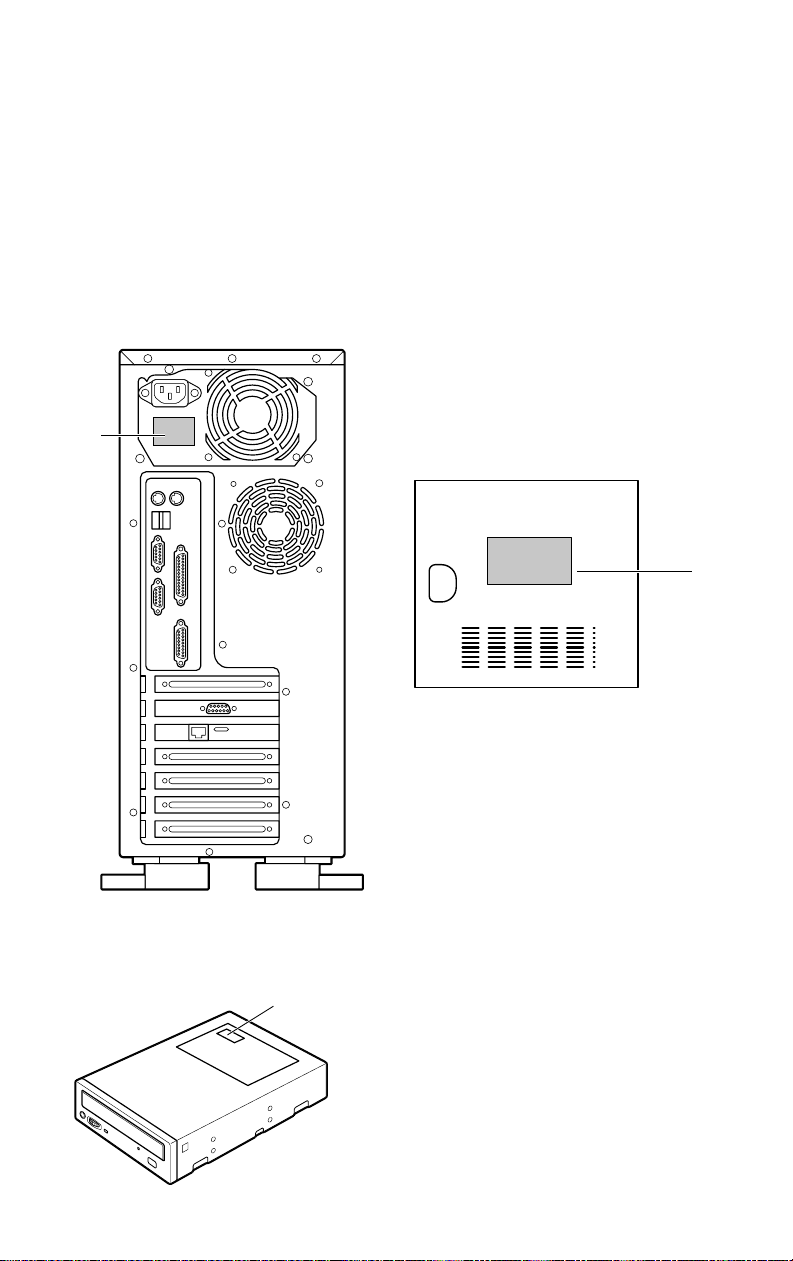
Warning Label
W arning l abels are attached to some of the equipment units, as
shown belo w .
For safe use of this equipment, read these labels carefull y
!
"
Internal view of the left side panel
Rear view
CD-ROM drive
#
Page 3
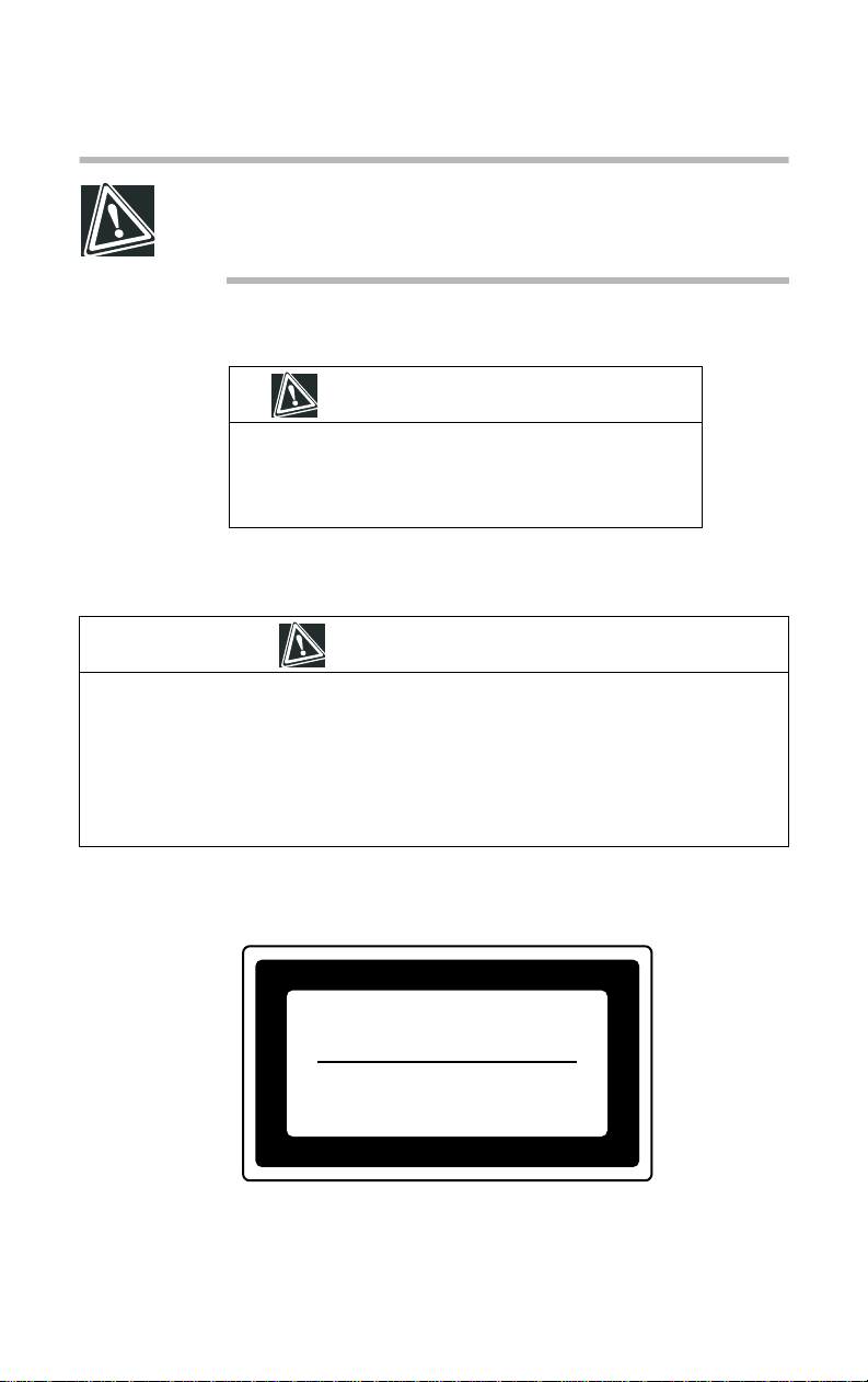
CAUTION: Never remove the warning and caution labels.
If the labels become dirty and illegible, contact Toshiba Technical Support or your local Toshiba dealer.
1. CAUTION label
CA UTION
DANGER: Power supply poses hazards of electrical shock
injury to personnel and damage to equipment.
It should be removed and replaced only by t rained service
technicians
2. CAUTION label
CA UTION
When configuring the server, observe the precautions listed below:
1. T o pre vent being injured by fans or an electric shock.,first switch off the server and disconnect the power cable
2. Disconnect cables inside the server carefully to prevent your hand from hitting against the
inside of the server and being injured.
3. To pre vent injury to your hands carefully remove the expansion cards by their edges.
3. Handling the laser product
CLASS 1 LASER
PRODUCT TO IEC 60825-1
LASER KLASSE 1
N
ACH IEC 60825-1
Page 4

CAUTION: This appliance contains a laser system and is
classified as a “CLASS 1 LASER PRODUCT.”
To use this model correctly, read the instruction manual
carefully, and keep it for your future reference.
If problems are encountered with this model, please contact your nearest “AUTHORIZED service provider.”
To prevent direct exposure to the laser beam, do not try to
open the enclosure.
Use of controls or adjustments, or performance of procedures other than those specified in the owner’s manual,
may result in hazardous radiation exposure.
Page 5

Copyright
This guide is copyrighted by T oshiba Corporation, all rights reserved. Under the
copyright laws, this guide cannot be reproduced in any form without the prior
written permission of Toshiba. No patent liability is assumed, however, with
respect to the use of the information contained herein.
©2002 by T oshiba Corporation. All rights reserved.
The software is owned by Adaptec, Inc. and is protected by United States copy-
right laws and international treaty provisions. Y ou may not alter or remove any
copyright notices which Adaptec, Inc. has caused to appear in the software or
documentation.
Disclaimer
The information contained in this manual, including but not limited to any
instructions, descriptions and product specifications, is subject to change without
notice.
TOSHIBA CORPORATION PROVIDES NO WARRANTY WITH
REGARD TO THIS MANU A L OR ANY OT HER INFORMATION CONT AI NED HEREI N AN D HEREBY EXPRESS LY DISCLAIMS ANY
IMPLIED WARRANTIES OF MERCHANT ABILITY OR FITNES S
FOR ANY PARTICU LAR PUR POSE W ITH REGARD T O ANY OF
THE FOREGOING. TOSHIBA ASSUMES NO LIABILITY FOR ANY
DAMAGES INCURRED DIRECT LY OR INDIRECTL Y FR OM ANY
TECHNICAL OR TYPOGRAPHICAL ER R ORS OR OMI SSIONS
CONTAINED HEREIN. IN NO EVEN T SHALL T OSHIB A BE LIABLE
FOR ANY INCIDENTAL, CONSEQUENTIAL, SPECIAL, OR EXEMPLARY D A MAGES, WHETHER BASED ON TORT, CONTRACT OR
OTHER WISE, ARISING OUT OF OR IN CONNECTION WITH THIS
MANU AL OR ANY OT HER INFORMATION CONTAINED HEREIN
OR THE USE THEREOF.
Page 6

Trademarks
MAGNIA is a trademark of Toshiba Corporation.
Pentium is a registered trademark of Intel of the United S tates.
IBM PC/AT , VGA and PS/2 are registered trademarks of International Business
Machines of the United States.
MS, Microsoft, and its logos MS-DOS, Wndows, and Windows NT are re gis-
tered trademarks of Micorsoft of the Untited States.
NetW are is a registered trademark of Novel of the United States.
Ethernet is a registered trademark of Fuji Xerox, and its logo is a registered trade-
mark of the United States.
MegaRAID. FlexRAID and Power Console are registered trademarks of LSI
Logic of the United States.
TNT2 and VANTA are registered trademarks of nVIDIA, and their logos are reg-
istered trademarks of the United States.
Other product names and trademarks belong to the individual companies con-
cerned.
Page 7
TOSHIBA
Toshiba declares, that the product: SYU315**-***** conforms to the f ollowing S tandards:
Toshiba erklärt, da
Toshiba déclare que le produit cité ci-dessocus:
SYU315**-***** est conforme aux normes suivantes:
Toshiba declara que el producto: SYU315**-***** cumple los sigulentes estándares:
Toshiba dichiara, che il prodotto: SYU315**-***** è conforme alle seguenti norme:
Toshiba intygar att produkten: SYU315**-***** överensstämmer med följande normer:
das Produkt: SYU315**-***** folgenden Normen entspricht:
β
EU Declaration of Conformity
EU Übereinstimmugserklärung
Déclaration de conformité UE
Declaración de conformidad de la UE
Dichiarazione di conformità UE
EU Försäkran om Överensstämmelse
Supplementary Information: “The product complies with the requirements of the Low Voltage
Weitere Informationen: “Das Produkt entspricht den Anforderungen der Niederspan-
Informations complémentaires: “Ce produit est conforme aux exigences de la directive sur les
Información complementaria: “El Producto cumple los requistos de baja tensión de la Directiva
Ulteriori informazioni: “Il prodotto é conforme ai requisiti della direttiva sulla bassa ten-
Ytterligare information: “Produkten uppfyller kraven enligt lägspänningsdirektiver
This product is carrying the CE-Mark in accordance with the related European Directives. The
company responsible for CE-Marking is Toshiba Europe, Hammfelddamm 8, 41460 Neuss,
Germany .
$
Notice to user of EN55022
Directive 73/23/EEC and the EMC Directive 89/336/EEC.”
nungs-Richtlinie 73/23/EG und der EMC-Richtlinie 89/336/EG. ”
basses tensions 73/23/CEE et de la directive EMC 89/336/CEE. ”
73/23/CEE y la Directiva EMC 89/336/CEE. ”
sione 73/23/EG e la direttiva EMC 89/336/EG.”
73/23/EEC och EMC-direktiv 89/336/EEC.”
WARNING: This is a Class A product. In a domestic environment this product may cause radio interference in which
case the user may be required to take adequate measures.
Page 8

Introduction
Features of the MAGNIA 550D
$
Dual Pentium® III processors and VIA Apollo Pro 133T
chipset
$
Pentium® III processors (1 GHz, 1.13 GHz, 1.26 GHz, 1.4
GHz)
$
256 kB secondary cache (1 GHz Pentium® III)
$
512 kB secondary cache (1.13 GHz, 1.26 GHz, 1.4 GHz)
$
Main memory expandable to 2 GB
$
48X-speed CD-ROM dri ve
$
Server setup support software “Serv er Setup Tool for
MAGNIA 550D”
$
System operation managetment software “HarnessEye/web”
$
Network adapter which supports Wake On LAN
$
Compatible with RAID 0, 1, 5, and 10
$
Five PCI bus slots (One slot occupied by a LAN card)
$
AGP b us slot (Occupied by a video card)
ix
Page 9
x
$
Four 5.25-inch device bays (One slot occupied b y a CD-R OM
drive)
$
Three 3.5-inch device bays (One slot occupied by a Flopp y
disk driv e)
NOTE: The MAGNIA 550D meets the FCC regulations for
a Class A digital device, suitable for use in a business
installation. A possibility of radio interference exists when
using the MAGNIA 550D in a home environment.
About this guide
This guide introduces the MAGNIA 550D’s features and explains
how to set up, configure, and maintain the serv er .
Please read carefully through this guide to gain an ov erall understanding of operating procedures and safety precautions before
using the MA GNIA 550D serv er.
NOTE: There are limitations, which apply only to systems
with the current BIOS Release F1.B. Future releases of
BIOS may correct these limitations. Throughout this guide,
wherever these limitations may affect the performance of
the server, there will be notations and instructions to
explain them.
T o determi ne which BIOS revision your serv er is shipped with,
switch on the power.
The BIOS release version is displayed on the fourth line of the
Power On Self Test (POST) screen.
Page 10
Safety instructions
All safety instructions must be read carefully and must be fully
understood before attempting to use your Toshiba MAGNIA
Series Server .
This guide contains the safety instructions that must be observ ed
in order to avoid potential hazards which could result in personal
injuries or could damage your equipment. The safety instructions
have been classif ied according to the seriousness of the risk, and
the following icons highlight these inst ructions as follo ws:
DANGER: This icon indicates the existence of a hazard
that could result in death or serious bodily injury if the
safety instructions are not observed.
CAUTION: This icon indicates the existence of a hazard
that could result in damage to equipment or property if the
safety instructions are not observed.
xi
WARNING: This icon indicates the existence of a hazard
that could result in bodily injury if the safety instructions are
not observed.
NOTE: This icon indicates information that relates to the
safe operation of the equipment or related items.
It is extremely importa nt that the basic safety practices be followed
when installing any unit or maintaining the system.
Page 11
xii
Other icons used
Additional icons highlight other helpful or educational
information:
TECHNICAL NOTE: This icon provides technical information about the server which, while not essential, may be of
interest to you.
HINT: This icon denotes helpful hints and tips.
DEFINITION: This icon indicates the definition of a term
used in the text.
Other documentation
$
The MAGNIA 550D User’s Guide (This guide)
Be sure to read this guide first.
This guide explains information necessary to use this serv er ,
the procedure to install the OS, the procedure to add options,
troubleshooting, and the equipment specifications and other
items.
Keep this guide handy to check your work while working on
the server.
$
Server Setup Tool for MAGNIA 550D User’s Guide
This guide explains the server conf iguration support softw are
(Server Setup Tool for MAGNIA 550D) operating procedure,
the procedure to automatically install Microsoft® Windo ws
NT® Server Version 4.0/Windows® 2000 Server that Ser ver
Setup T ool for MAGNIA 550D uses, the procedure to create
various floppy disks, the operating procedure for the diagnostic
program and other items.
Page 12

Refer to this guide to manually install Microsoft® W indo ws
NT® Server Version 4.0/Windows® 2000 Server.
$
HarnessEye/web User’ s Guide
This guide explains the configuration and operati ng procedure
for the integrated server operating management softw are (HarnessEye/web). HarnessEye/web only operates on Microsoft®
Windo ws NT® Server Version 4.0/Windo ws® 2000 Server.
$
Read-Me First Addendum
Also, when necessary read the other manuals that are enclosed
and the manuals that belong to the peripheral devices.
$
Safety Instruction Guide
Service options
T oshiba of fers a full line of service options b uilt around its warranty programs. See the warranty and service material included
with the server for re gistration informa tion.
xiii
Maintenance contracts
Periodic maintenance and inspection is essential for k eeping the
server fully operational and assuring its safe use. Toshiba recommends taking out a maintenance contract for this purpose.
Page 13

Contents
Chapter 1: Getting Started............................................................................. 2
Make sure you have everything ................................................................ 3
Installing optional internal devices ............................................................. 4
Installing the server...................................................................................... 5
Footplate.................................................................................................. 5
Environmental considerations............................................................... 6
Front view (with the front doors closed).................................................... 9
Key-operated lock................................................................................ 10
Front view (with the front doors opened)................................................ 11
5.25-inch device bay ........................................................................... 12
3.5-inch device bay.............................................................................. 13
Operation buttons................................................................................ 15
System status indicators..................................................................... 16
Hard disk drives ................................................................................... 17
Rear of the server..................................................................................... 18
Power supply unit ................................................................................ 18
I/O ports................................................................................................. 19
AC power connector ........................................................................... 20
Expansion slots.................................................................................... 20
Removing and replacing the server panels .......................................... 21
Page 14

xvi
Removing the front door panel........................................................... 21
Replacing the front door panel........................................................... 22
Removing the side panel .................................................................... 23
Replacing the side panel..................................................................... 25
Inside the server........................................................................................ 26
Motherboard......................................................................................... 26
Memory slots........................................................................................ 26
Cooling fans.......................................................................................... 27
CPU socket........................................................................................... 27
Internal battery...................................................................................... 27
Expansion slots.................................................................................... 27
Connecting peripheral devices................................................................ 28
Connecting the power cable.................................................................... 30
Turning on the server ............................................................................... 31
Turning on the server........................................................................... 31
Turning on the server by the “Wake On LAN” function................... 31
Power On Self Test (POST).................................................................... 32
Starting the server..................................................................................... 33
Starting the server from the floppy disk drive ................................... 33
Starting the server from the hard disk drive
(if an operating system is installed on it)............................................ 33
Starting the server from the CD-ROM drive..................................... 34
BIOS setup ................................................................................................ 35
Backup floppy disk.................................................................................... 36
Creating a backup floppy disk ............................................................ 36
Setting the system configuration............................................................. 37
Setting up a disk array (RAID)................................................................. 38
Installing software...................................................................................... 39
Turning off the server................................................................................ 40
Normal shutdown................................................................................. 40
If the operating system does not shut down normally..................... 40
Chapter 2: Connecting Hardware Devices............................................... 42
Installing and removing optional devices............................................... 42
Before you start.................................................................................... 43
Installing and removing methods....................................................... 48
Page 15

xvii
Memory modules...................................................................................... 49
Installing a memory module............................................................... 51
Removing a memory module ............................................................ 53
CPU module.............................................................................................. 54
Installing a CPU module..................................................................... 55
Replacing the CPU module ............................................................... 59
Replacing the internal battery.................................................................. 64
Hard disk drive (HDD) – IDE HDD –...................................................... 67
IDE interface......................................................................................... 67
Jumper switch setting for hard disk drives........................................ 68
Installing a hard disk drive (expansion)............................................. 68
Removing a hard disk drive................................................................ 72
Hard disk drive (HDD) – SCSI HDD –................................................... 74
SCSI interface ...................................................................................... 74
Jumper switch setting for hard disk drives........................................ 74
Installing a hard disk drive (expansion) –3.5-inch device bay–...... 75
Removing a hard disk drive –3.5-inch device bay–........................ 79
Installing a hard disk drive (expansion) –5.25-inch device bay–... 81
Removing a hard disk drive –5.25-inch device bay–...................... 83
SCSI devices............................................................................................. 85
SCSI ID................................................................................................. 85
Termination........................................................................................... 85
Installing a SCSI device in the 5.25-inch device bay....................... 86
Removing a SCSI device out of the 5.25-inch device bay............. 89
Installing a SCSI device in the 3.5-inch device bay......................... 90
Removing a SCSI device out of the 3.5-inch device bay............... 94
Expansion cards....................................................................................... 96
Installing PCI expansion cards........................................................... 96
Removing PCI expansion card.......................................................... 99
Points of RAID controller and SCSI host adapter connection ..... 100
Uninterruptible power supply unit (UPS) ............................................. 101
Chapter 3: System Configuration Setup................................................. 104
BIOS Setup Utility................................................................................... 104
Starting the BIOS Setup Utility......................................................... 105
Menu window..................................................................................... 106
Page 16

xviii
Changing BIOS settings ................................................................... 109
BIOS settings...................................................................................... 110
Resetting all setup options to their default values.......................... 130
Chapter 4: Installing Software .................................................................. 132
Windows NT® Server 4.0...................................................................... 132
Before installing Windows NT Server 4.0....................................... 132
Installing Windows NT Server 4.0 automatically ........................... 133
Installing Windows NT Server 4.0 manually .................................. 133
Procedure after installation of Windows NT Server 4.0................ 137
Windows® 2000 Server......................................................................... 140
Before installing Windows 2000 Server.......................................... 140
Installing Windows 2000 Server automatically .............................. 140
Installing Windows 2000 Server manually ..................................... 140
Procedure after installation of Windows 2000 Server................... 143
NetWare................................................................................................... 146
Before installing the NetWare........................................................... 146
Installing the NetWare 5.1 manually................................................ 148
Installing the NetWare 4.2 manually................................................ 153
Procedure after installation of the NetWare.................................... 155
System Operation Management software
“HarnessEye/web”.................................................................................. 156
Chapter 5: Troubleshooting...................................................................... 158
Troubleshooting...................................................................................... 158
You can hear abnormal noise or smell foul odours, and hear a
continuous buzzer.............................................................................. 158
Nothing happens if you press the power switch. Or, nothing appears
on screen even though you can hear the server running............. 159
Characters are distorted or not displayed properly........................ 160
The disk indicator turns on abnormally ........................................... 160
The FDD indicator does not light ..................................................... 161
An error is displayed during POST operation, or POST stops midway
161
Loading of RAID controller BIOS stops midway............................ 161
Cannot install the Operating System (OS)..................................... 162
The Operating System does not boot, or the Operating System
Page 17

xix
bootup stops midway........................................................................ 163
Windows NT/2000 is locked or cannot be used............................ 163
Trouble information or error log still remains in the system operation
management software and other software .................................... 164
The internal clock dose not keep the exact time............................ 164
The power button does not function after abortion........................ 164
Trouble with Application Software........................................................ 165
Remedy When Windows NT/2000 is Usable .................................... 166
Remedy When Windows NT/2000 is Unusable................................ 167
Appendix A: Specifications....................................................................... 170
Specifications ..................................................................................... 170
Appendix B: Interface................................................................................ 174
RGB interface..................................................................................... 174
Serial-1/2 interface............................................................................. 178
Keyboard/mouse interface............................................................... 179
Printer interface .................................................................................. 180
USB-0/1 interface .............................................................................. 181
LAN interface...................................................................................... 182
Expansion slots (for PCI expansion cards).................................... 183
Appendix C: Clearing the CMOS............................................................ 188
Appendix D: Device Logs......................................................................... 192
About the device logs........................................................................ 192
Basic system configuration............................................................... 193
CPUs................................................................................................... 193
Memory............................................................................................... 193
Hard disk drives ................................................................................. 194
SCSI devices...................................................................................... 194
Expansion cards................................................................................ 195
Other optional devices ...................................................................... 195
Page 18

Chapter
Make sur e you ha ve ev erythi ng .................... ........ ........ ......... ..... 3
Installing optional internal devices ............................................. 4
Installing the server ....................................................................... 5
Front vie w (wi th the fron t doors closed) ........ ........ ........ ......... ... 9
Front vie w (wi th the fron t doors opened) .............. ........ ......... . 11
Rear of the server ........................................................................ 18
Removing and repl acing the s erve r panels .. ........ ........ ....... ..... 21
Inside the server .......................................................................... 26
Connecting peripheral devices .................................................. 28
Connecting the power cable ...................................................... 30
Turning on the server .................................................................. 31
Power On Self T est (POST) ...................................................... 32
Starting the server ....................................................................... 33
BIOS setup .................................................................................. 35
Backup floppy disk ..................................................................... 36
Setting the system configuration ............................................... 37
Setting up a disk array (RAID) ................................................. 38
Installing software ....................................................................... 39
Turning off the server ................................................................. 40
1
Page 19

Getting Started
This chapter describes how to set up your server and get st arted.
2
Page 20

Make sure you have everything
Make sure you have everything
Be sure to check the contents of the package against your purchase
order . If any items are missing or damaged, please notify your
T oshiba dealer i mmediately.
NOTE: The purchase order provides a listing of all standard
accessories and their quantities. If you purchased the server
with optional devices, the optional devices are also
deliveredwith the standard accessories listed. In such a case,
however, it is possible that the quantities of some
accessories, e.g., brackets, do not agree with those specified
on the list, because they have already been used to fix the
optional devices. In contrast, if an expansion slot cover etc.
has been removed from the server to install an optional
device instead, the removed expansion slot cover is delivered
with the server as an accessory.
[Example]
If you purchase the server with a built-in DAT (Digital Audio
Tape) deck, all accessories of the DAT deck are also
delivered with the server as additional accessories, while the
device bay spacer, which was removed from a 5.25-inch slot
to install the DAT deck, is delivered as an accessory.
Getting Started
3
Before connecting the power cable to your serv er , remo ve the
front door panel and the side panel to ensure that all components
are installed correctly.
See “Removing and replacing the server panels” on page21.
Page 21

Getting Started
4
Installing optional internal devices
Installing optional internal devices
Install all optional device s, if any, before setting up the server.
See “Installing and removing optional de vices” on page 42.
If you have no experie nce installing or remo ving computer
hardware devices, or if the job seems dif f icult, always consul t
T oshiba Technical Support or your T oshiba dealer . (You will be
charged a service fee).
Page 22
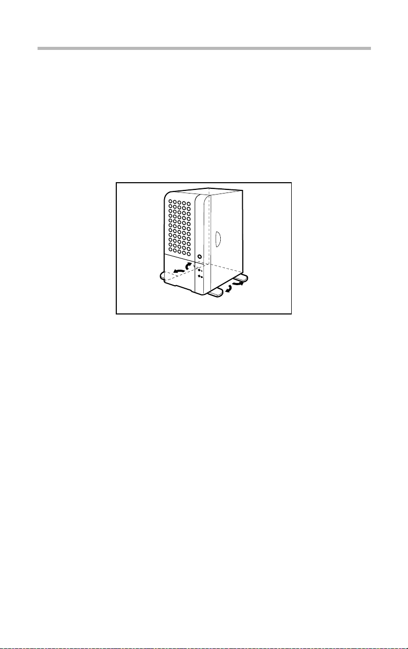
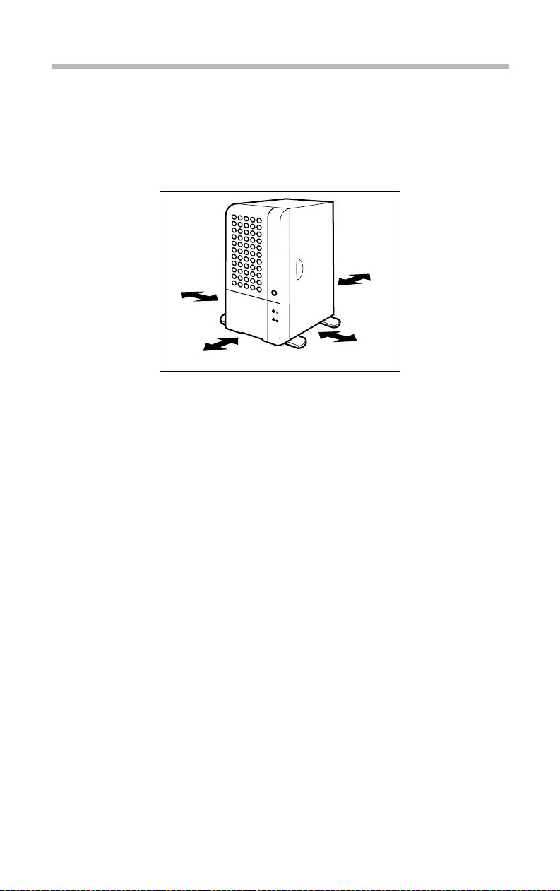
Installing the server
Footplate
Your server has four footplates at the bottom to prev ent the de vice
from toppling over.
Be sure to extend them before installing the serv er .
Getting Started
Installing the server
5
Footplates
Page 23
Getting Started
6
Installing the server
Environmental considerations
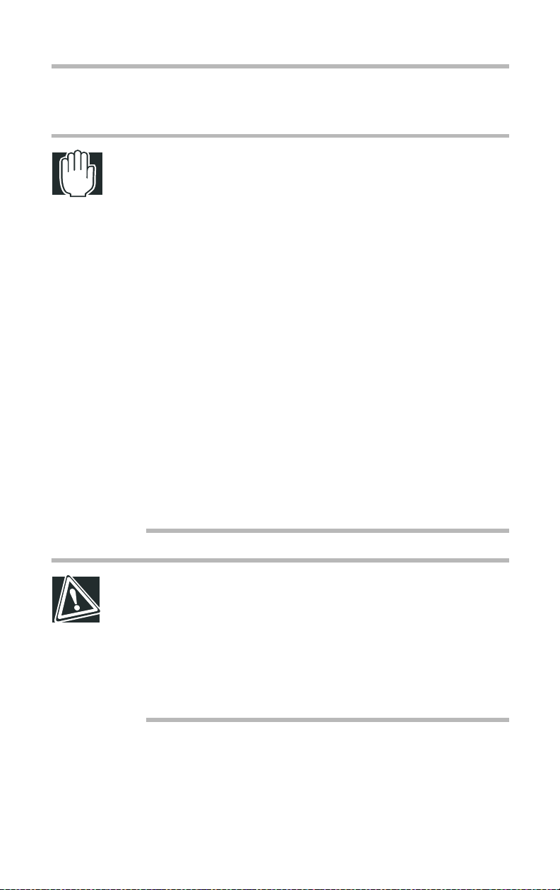
WARNING: If debris or liquid gets in to the server, shut it
down immediately, turn off the power button, and unplug the
power cable from the AC outlet. Failure to do so could result
in a fire or shock. Contact Toshiba Technical Support or your
Toshiba dealer to ask for service.
Do not install the server on an unsteady or slanted surface,
otherwise the server may fall over, causing injury.
Do not install the server in a dusty place. Dust can cause
short circuits that could lead to fire or smoke damage.
Do not install the server where it can be exposed to rain or
mist. Rain and mist could cause a fire or shock hazard.
Do not install the server in a poorly ventilated place. Blocking
air vents or installing the server where heat from the server
cannot be discharged will cause the temperature inside the
server to rise, causing risk of a fire.
Do not install the server where it can be exposed to corrosive
gases or salty air, this could cause the server to produce
smoke.
CAUTION: Do not install the server where it can be exposed
to vibration or shock, this could cause the server to topple
over, causing injury.
Do not install the server where the temperature can rise, for
example, exposure to direct sunlight or near to a heater, this
can cause the temperature inside the server to rise, causing
the possibility of fire in the worst case.
Page 24

Getting Started
Installing the server
$
Install the server in a clean, dust-free, and well- ventilated
place.
$
Install the server on a lev el and steady surf ace.
$
Do not install the server upside do wn.
$
Never inst all the server i n any of the follo wing places:
- Where it will be exposed to direct sunlight.
- Where it will be exposed to vibration or shock.
- Near any devices that generat e a strong magnetic f ield or
produce radio frequency noise, such as a radio, TV, large
motor, high-fr equency electric apparatus, air conditioner ,
large fan, or loudspeaker.
- Where the temperature and humidity change constantly, near
an air-conditioning vent, cooling fan, heater or heat source.
- Near liquids or corrosiv e chemicals.
7
$
Operate the server under the follow ing temperature and
humidity conditions:
- Ambient temperature: 10 to 35°C (50 to 95°F)
- Relative humidi ty: 30 to 80%Rh (no condensation)
CAUTION: To avoid damage from condensation when the
room temperature is too high or too low, switch on the server
about an hour after the room temperature falls within a range
of 10 to 35
Avoid exposing the server to condensation during use and
storage.
°C (50 to 95°F).
Page 25
8
Getting Started
Installing the server
$
Allow suf fici ent space around the server for inst allation and
maintenance.
The following illustrat ion shows the rec ommended minimum
clearances.
8 inches
2 inches
(5cm)
12 inches
(30cm)
Recommended minimum clearances
(20cm)
2 inches (5cm)
Page 26
Getting Started
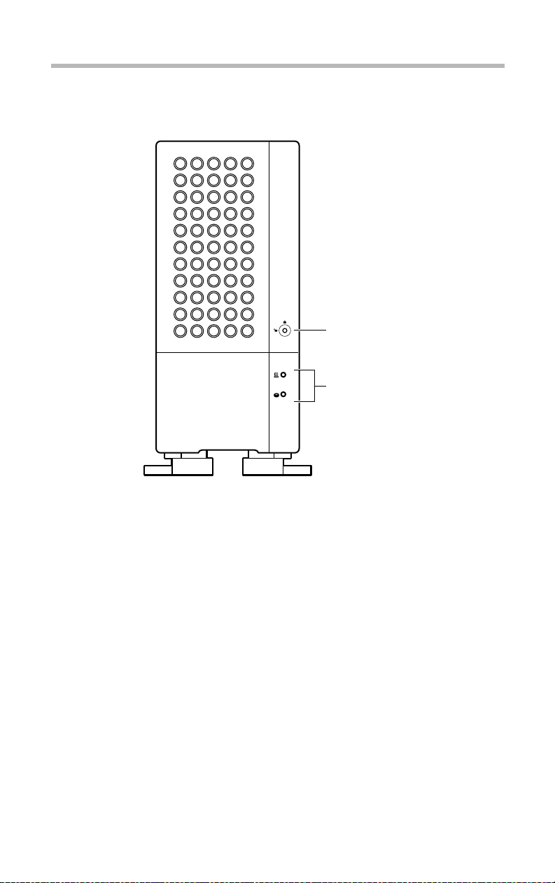
Front view (with the front doors closed)
Front view (with the front doors closed)
Key lock
System status
indicators
9
Front view with the front doors closed
Page 27
Getting Started
10
Front view (with the front doors closed)
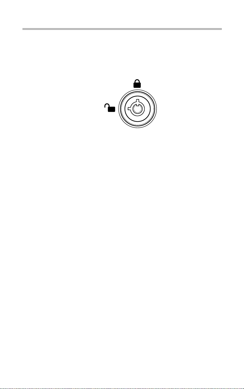
Key-operated lock
The front doors can be locked in two lev els: full acce ss and no
access, which depend on the direction of the keyhole.
Ke y-opera ted lock
No access
Full access
Page 28
Getting Started
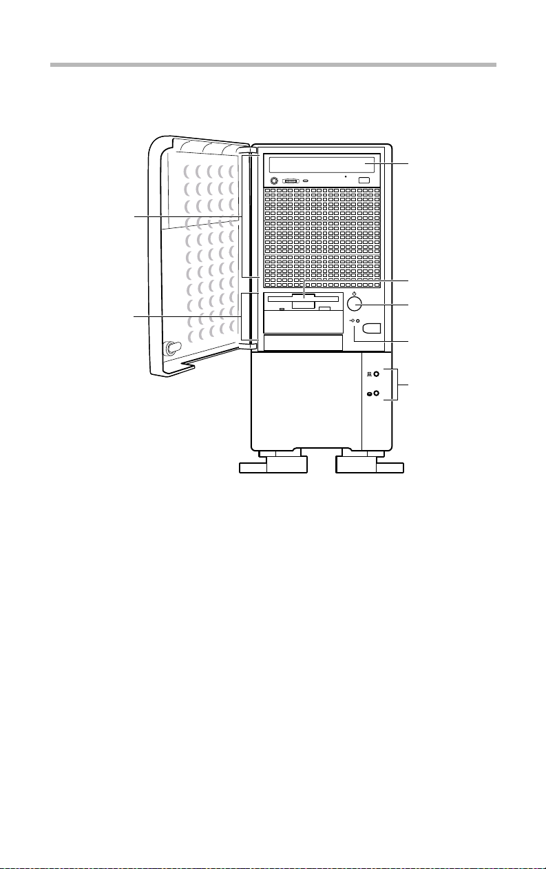
Front view (with the front doors opened)
Front view (with the front doors opened)
5.25" device bay
3.5" device bay
11
CD-ROM drive
Floppy disk drive
Power button
Reset button
System status
indicator
Front view with the front door opened
Page 29
Getting Started
12
Front view (with the front doors opened)
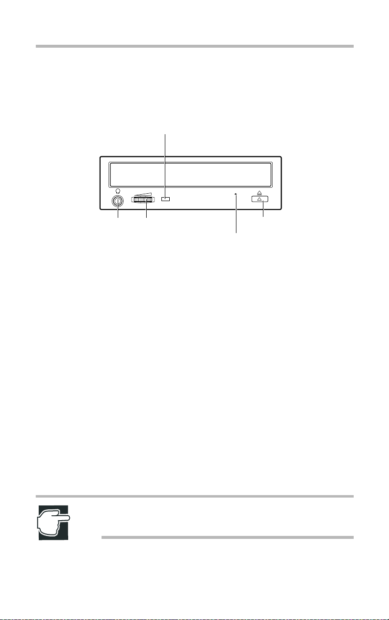
5.25-inch device bay
CD-ROM drive
CD-ROM drive status indicator
Stereo
phone jack
Front view of the CD-ROM drive
The CD-ROM dri ve supports both single- size (5.25") and
standard-size (8") CD-R OMs.
$
Disk tray
Used to set a CD-R OM. Press the ej ect button to slide the disk
tray in or out of the CD-ROM dri ve.
$
Stereo phone jack
Used to connect a headphone or e arphone.
$
Volume control
Used to adjust the audio output level of the ste reo phone jack.
$
CD-ROM dri ve status indic ator
Lights up while the CD-R OM is being accessed.
$
Eject button (button on the r ight side)
Used to slide the disk tray out when there is no power cable
connected to the CD-ROM dri v e.
Volume control
Eject button
Eject hole
NOTE: The button on the left side is inoperative with this
system.
Page 30

Getting Started
Front view (with the front doors opened)
$
Eject hole
Used to eject the disk tray if it does not slide out while you
press the eject button. Insert a fi ne wire (e.g., straightened
paper clip) into this hole to forcefully eject the tray.
NOTE: Be sure to turn off the server beforehand when
ejecting the disktray using the eject hole.
Do not insert any fragile pin, such as a mechanical pencil lead
or a plastic pin.
Do not press the eject button when the CD-ROM drive status
indicator is lit. Otherwise, the CD-ROM drive might fail.
After using the CD-ROM drive, always remove the CD-ROM
from it.
The disk trays of some CD-ROM drives are provided with
disk holders. Do not use the disk holder along with this
system, except when the system is used as a rack model.
13
When ejecting the disk tray without using the eject button or
eject hole, open the front door beforehand.
3.5-inch device bay
The 3.5-inch device bay can accommodate up to three 3.5-inch
devices. (One of the three slots is already occupied b y a floppy
disk drive and one or two slots b y other magnetic disk dri v es.)
Floppy disk drive
The floppy disk drive supports 3.5-inc h 2DD (720 kB) and 2HD
(1.44 MB) floppy disks.
Page 31

14
Getting Started
Front view (with the front doors opened)
Status indicator Eject button
Front view of the floppy disk drive
$
Status indicator
Illuminates green while data is being read from or written on
the floppy disk.
$
Eject button
Used to eject the floppy disk from the floppy disk dri ve.
NOTE: To avoid loss or corruption of data stored on the floppy
disk, never turn off or reset the server, or press the eject
button while the status indicator is on.
Remove the floppy disk from the floppy disk drive whenever
the drive is not in use.
Page 32

Operation buttons
The server has the following tw o b uttons on the front panel.
Operation buttons
Power button Press to switch the server on or off.
Getting Started
Front view (with the front doors opened)
Power button ( )
Reset button ( )
15
Reset button Press to reset the system (use a small
slender object).
NOTE: To avoid losing data or damaging drives, never switch
off or reset the server when the FDD status indicator, CDROM drive status indicator, or HDD status indicator is on.
The procedure for turning the server on and off depends on the
operating system installed.
See “Turning on the serv er” on page 31 and “Turning off the
server” on page40.
Page 33

Getting Started
16
Front view (with the front doors opened)
System status indicators
The server has the following tw o indicators (LEDs) to indi cate its
status.
System status indicators
Power
indicator ( )
Disk
indicator ( )
Indicator (LED) Status Meaning
Power Off Out of operation
Green In operation
Hard disk drive
(HDD)
NOTE: If a fault occurs, please contact Toshiba Technical
Support or your local Toshiba dealer.
To avoid losing data or damaging drives, never turn off or
reset the server when the HDD status indicator is on.
Off Out of operation
Flashing green Disk driv e in operation
Page 34

Hard disk drives
The HDD status indicator ( ) flashes green while the har d disk
drive reads or writes data.
NOTE: To avoid damaging disks and losing data, be careful
not to disturb, vibrate or shock the hard disk drives when
handling them.
The installation and replacement of a hard disk drive requires
special know-how and techniques. Contact Toshiba Technical
Support or your local Toshiba dealer for assistance. Incorrect
installation or replacement of a hard disk drive may result in
corruption or loss of the important programs or stored data.
To avoid damaging data areas, do not disturb or shake the
server when it is on.
The head of a hard disk drive remains in a data area without
returning to its original position, even if the HDD status
indicator is off, until the server is turned off. It takes about 30
seconds for a hard disk drive to run down and come to a full
stop.
Getting Started
Front view (with the front doors opened)
17
Page 35

Getting Started
18
Rear of the server
Rear of the server
Keyboard port ( )
Mouse port ( )
USB port 0 ( )
USB port 1 ( )
Serial port 1 ( )
Printer port ( )
Serial port 2 ( )
GAME port
RGB port ( )
LAN port ( )
Full-duplex (FULL)
Speed indicator (100M)
Link status indicator (LINK)
Ether
Rear view
AC power connector
Power supply unit
Air vents
(FAN)
Expansion slots
Power supply unit
The server has a built-in po wer supply unit as standard .
Page 36

I/O ports
Getting Started
Rear of the server
I/O ports allow peripheral de vices to be connected to the serv er .
$
Keyboard port ( )
Used to connect the keyboard (supplied with the server) .
$
Mouse port ( )
Used to connect the mouse (supplied with the server).
$
Parallel port ( )
Used to connect a printer .
$
USB ports ( )
Used to connect USB (Universal Serial Bus) device s. (When
connecting a USB device, ensure that the operating system
installed supports USB.)
$
RGB port ( )
Used to connect the monitor .
19
$
LAN port ( )
Used to connect to a 100B ASE-TX/10BASE-T Ethernet LAN.
$
Full-duplex (FULL)
On...Full-duplex communications
Off...Half-duplex communications
$
Link status indicator (LINK)
Indicates the communication status.
On ... Correctly connected and on standby
Flashing ... In communication
Off ... Network cable not connected or connected incorrectly
$
Speed indicator (100M)
Indicates the data transfer speed.
On ... Data transferred at 100 Mbps
Off ... Data transferred at 10 Mbps
$
Serial port 1 (COM1) ( )
Used to connect an RS-232C device.
$
Serial port 2 (COM2) ( )
Used to connect an RS-232C device.
Ether
Page 37

Getting Started
20
Rear of the server
$
GAME port
This port CANNOT be used for your serve r .
See “Connecting peripheral devices” on page 28.
AC power connector
Used to connect a po wer c able.
Expansion slots
The server has fi ve PCI slots to allo w you to install expansion
cards. (One slot is occupied by a LAN card).
Page 38

Getting Started
Removing and repl acing the server panels
Removing and replacing the server panels
T o install some optional de vices, the front door panel and the side
panel must be detached.
T w o panels can be opened: the front door panel and the si de panel.
The front door panel should always be detached first , followed b y
the side panel. T o repl ace them, rev erse the order of remo v al.
Removing the front door panel
NOTE: Do not remove the front door panel forcibly. Doing so
may cause damage to the plastic hooks and make it
impossible to replace the front door panel.
T o remo v e the front door panel, proceed as follo ws: 1 Shut down and turn off the server if it is in operation.
21
2 Unplug the power cable from the A C outlet. 3 Release the key-lock, pull do wn the latch of the lo wer front
door panel, and pull it toward you.
The lower front door panel will be detached.
Removing the fr ont door panel
Page 39

22
Getting Started
Removing and replacing the server panels
4 Remove the front door panel b y releasing the two plastic hooks
located onthe upper part of the server .
Removing the fr ont door panel
NOTE: When releasing the plastic hooks, be careful not to
break them.
Replacing the front door panel
T o re place the front door panel, proceed as follo ws:
1 Attach the front door panel by fitting the plastic hooks located
at the upper and middle parts of the door panel in to the mounting holes on the server .
Page 40

Getting Started
Removing and repl acing the server panels
Attaching the fr ont door panel
NOTE: Push the hooks enough into the holes being careful
not to break them.
2 T o attach the lo wer part of the door , fit the latch at the lo wer
part of the door panel in to the corresponding hole in the server
23
3 Plug the power cable in to an A C outle t.
Removing the side panel
T o remo v e the side panel, proceed as follo ws:
1 Shut down and switch off the server if it is in operation. 2 Unplug the power cable from the A C outlet. 3 Release the key-lock and remo ve the front door panel.
Page 41

24
Getting Started
Removing and replacing the server panels
4 Remove the scre ws securing the left -side panel.
Removing the scr ews
5 Remove the left-side panel b y sliding it to ward the f ront of the
server while pressing down on its upper part.
Detaching the side panel
Page 42

Removing and repl acing the server panels
Replacing the side panel
T o replace the si de panel, proceed as follo ws
1 Slide the left-side panel toward the rear of the server until it i s
locked, then using screws sec ure it to the serv er chassis.
Before securing the side panel with screws, check whether the
plastic hooks at the upper and lower parts of the side panel f it
in their corresponding holes in the server chassis.
Getting Started
25
Attaching the side panel
2 Attach the front door panel. 3 Plug the power cable in to an A C outle t.
Page 43

Getting Started
26
Inside the server
Inside the server
Power supply
unit
CPU socket
Memory slots
5.25-inch
device bays
3.5-inch
device bays
Expansion
slots
Inside the server
Motherboard
The motherboard can accommodate up to two CPU modules and
five PCI e xpansion cards. (One PCI slot is occupied b y a LAN
card)
Memory slots
The server has four memory slots that allo w you to install up to
four memory modules (128/256/512 MB).
See “Memory modules” on page 49.
Cooling fan
Internal battery
Motherboard
Page 44

Cooling fans
The server contains cooling fans for each component.
NOTE: Never block up air vents.
CPU socket
Used to install a CPU module.
See “CPU module” on page 54.
Internal battery
Used to manage the system time, and R TC (Real Time Clock)
battery . The internal batte ry is installed on the motherboar d.
See “Replacing the internal battery” on page 64.
Getting Started
Inside the server
27
Expansion slots
Used to install optional expansion cards. There are f iv e PCI2.2compliant PCI slots on the motherboard.
See “Expansion cards” on page 96.
Page 45

Getting Started
28
Connecting peripheral devices
Connecting peripheral devices
The rear panel of the server is provided with I/O ports that allo w
you to connect peripheral devices, such as a ke yboard, a mouse
and a monitor . Before turning on the serv er , connect all peripher al
devices according to the steps described bel ow.
1 Make sure that the server and all the peripheral devices are off. 2 If the power cable of the serv er or any peripheral de vice is
plugged in to an AC outlet, unplug it.
3 Connect the interface cables of all peripheral de vices to the
corresponding ports on the server .
Pay attention to the orientation of the connectors when
inserting them.
Connecting peripheral devices
4 If mounting screws are provided for connectors, tighten them
securely .
Page 46

Getting Started
Connecting peripheral devices
5 Check that all devices are connected correctly, then plug the
power cables of the serv er and peripheral de vices in to AC outlets.
WARNING: To avoid the risk of a fire, always use Toshiba
genuine devices or devices recommended by Toshiba. For
optional devices available, contact Toshiba Technical Support
or your local Toshiba dealer.
NOTE: When connecting or removing an interface cable, do
not hold the cable itself but by its plug.
Some third-party devices and cables cannot be used with
your server. Consult the dealer before purchasing a device or
cable.
When connecting a peripheral device, refer to its instruction
manual.
29
Page 47

Getting Started
30
Connecting the power cable
Connecting the power cable
NOTE: Toshiba recommends that an uninterruptible power
supply (UPS) should be used to avoid losing data when an
unexpected system shutdown or power failure occurs.
After connecting all peripheral de vices, connect the power cable to
your server as follo ws:
1 Plug the power cable in to the A C po wer connector at the rear
of the server .
Connecting the power cable
2 Plug the power cable in to an A C outle t or an uninterruptible
power supply (UPS).
WARNING: Use the power cable supplied with the server.
The use of another cable could cause a fire risk.
Plug the power cable in to a grounded AC outlet. Failure to do
so could cause a fire risk or electric shock.
Do not hold the power cable itself but by its plug when
unplugging it, otherwise the cable may be damaged, causing
a fire risk or electric shock.
NOTE: Do not share an AC outlet for the server and other
electrical equipment, such as an air conditioner or
photocopier. These consume large amounts of electrical
power as well as producing radio frequency noise.
Page 48

Turning on the server
NOTE: Do not switch the server back on again within 10
seconds after turning it off. Turning it back on again within 10
seconds may cause it to malfunction or break down.
Do not turn on the server before connecting all peripheral
devices.
Turning on the server
T o turn on the serv er , proceed as follo ws:
1 Ensure that all the peripheral devices, including the monitor,
keyboard, and mouse, are correctly connected to the serv er .
2 Ensure that all power cables are connected to grounded A C
outlets or to an uninterruptible power supply (UPS).
Getting Started
Turni ng on the server
31
3 Turn on the monitor. 4 Press the power button on the ser ver.
Check that the green power ON indicator ( ) is ON.
Turning on the server by the “Wake On LAN” function
This server has the “Wake On LAN” function that the server can
be started up by a client who is in connection with the network.
Page 49

Getting Started
32
P ower On Self Test (POST)
Power On Self Test (POST)
Pressing the power button on the f ront panel of the server switches
the server ON and starts the Power On Self Test (POST). The
POST automatically checks the motherboard, microprocessors,
memory , ke yboard and peripheral de vices connected to the server.
During the memory test, the POST accesses and checks the
server’ s memory, and displays its memory available on the screen.
During POST , a message as sho wn belo w is displayed in the
lower-lef t hand corner of the screen.
Hit DEL if you wa nt to r un SET UP
If the <Delete> key is pressed at this stage, the BIOS Setup Utility
starts. If the <Delete> key is not press ed, the system continues to
start up.
If an error is detected during POST, a buzzer sounds (beep code)
or an error message is displayed, depending on the error type.
Page 50

Getting Started
Starting the server
Starting the server
The server can be started from any of th e follo wing devices: hard
disk drive, floppy disk dri v e, and CD-R OM dri ve.
Starting the server from the floppy disk drive
T o start the se rver from t he floppy disk dri ve, proceed as follow s:
1 Insert a bootable floppy disk in the floppy disk drive. 2 Switch on the server .
Starting the server from the hard disk drive (if an operating system is installed on it)
T o start the se rver from t he hard disk dri ve, proceed as follo ws:
1 Ensure that no floppy disk is inserted in the floppy disk drive. 2 Switch on the server .
33
NOTE: The server does not start in some system
configurations.
Check the system configuration, and set the starting order of
the 1st, 2nd, and 3rd boot drives in the “BIOS FEATURES
SETUP” dialog box of the BIOS Setup Utility.
See “System Configuration Setup” on page 104.
Page 51

Getting Started
34
Starting the server
Starting the server from the CD-ROM drive
T o start the server from t he CD-R OM dri ve , proceed as follo ws: 1 Change the starting order of boot devices, as described below .
In the “BIOS FEATURES SETUP” dialog box of the BIOS
Setup Utility , specify the CD-R OM drive as the 2nd boot dri ve,
and the current 2nd boot drive as the 3rd boot dri ve.
See “System Configuration Setup” on page104.
2 Ensure that the floppy disk driv e is empty. 3 Switch on the server . 4 Once the server is switched on, immediately press the eject
button of the CD-R OM dri ve and load a bootable CD-R OM.
NOTE: The eject button of the CD-ROM drive is only
operative when the server is on. To start the server from
the CD-ROM drive, you need to load a bootable CD-ROM
in the CD-ROM drive immediately after turning on the
server.
If you fail to load the startup CD-ROM in time, press the
<Ctrl>, <Alt>, and <Delete> keys simultaneously to restart
the server.
Once the server recognizes the presence of a bootable
CD-ROM, it cannot start from the hard disk drive, even if
you remove the CD-ROM immediately after the server
recognizes it. If you want to boot the server from the hard
disk drive, press the <Ctrl>, <Alt>, and <Delete> keys
simultaneously to restart the server.
Page 52

BIOS setup
The factory default settings of the server can be changed using the
BIOS Setup Utility . Using this utility software, the BIOS set tings
can be changed even if no operating syste m is installed on the
server . The system settings that you mak e with the BIOS Setup
Utility are written in t he CMOS and flash mem ory , and tak e effect
when you restart the server .
The BIOS settings are referred to during the Power On Self Test
(POST). If the settings you make are not supported by the
hardware, an error message is displayed on the screen on
completion of the POST. In such a case, change the settings
properly using the BIOS Setup Utility.
See “System Configuration Setup” on page104.
Getting Started
BIOS setup
35
Page 53

Getting Started
36
Backup floppy disk
Backup floppy disk
The T oshiba serv er supporting software “Serv er Setup Tool for
MAGNIA 550D (hereinafter referre d to as Server Setup Tool)”
contains a program that allows you to create backup flopp y disks
of the drivers and utiliti es installed on your serv er . Mak e backup
copies of them as required and store them in a safe place.
Creating a backup floppy disk
T o create a backup flopp y disk with the Server Setup Tool,
proceed as follows, as well as follo wing the instr uctions giv en on
the screen.
1 Insert the Server Setup Tool CD-R OM in to the CD-ROM
drive and the Startup Disk into the flopp y disk dri ve. Start the
Server Setup Tool.
2 Select “Utility.” 3 Select “Create Floppy Disks.” 4 Select the name of the backup floppy disk you want to create,
and click “Create. ”
5 Insert a blank 1.44 MB formatted floppy disk in to the floppy
disk drive, a nd click “OK.”
If the Startup Disk is still loaded in the floppy disk dri ve,
remove it.
For information about the backup floppy disks to be created:
See “Installing Software” on page 132.
See User’ s guide of the Server Setup Tool (on the
Documentation CD).
Page 54

Setting the system configuration
Setting the system configuration
The system configuration for your server has been optimized
before shipment from the factory. However, if you add optional
devices or change the operating condition after purchase, you may
need to reconfigure the server.
See “System Configuration Setup” on page104.
NOTE: After changing the system configuration, always
make note of the changes you made.
Getting Started
37
Page 55

Getting Started
38
Setting up a disk array (RAID)
Setting up a disk array (RAID)
If you select “Simplified setup” in the “Select RAID
configuration” window during setup (using t he Server Setup
T ool), the disk arr ay (RAID) will be configured with a minimu m
number of default settings. Therefore there is no need to mak e
settings manually using the utility software that came with the
RAID controller .
If you select “Detailed setup” or “No setup” or if you want to set
up the disk array without using the Server Setup Tool, you need to
make settings manually.
See User’ s guide of the RAID controller.
If you add a RAID controller to your server , don’t for get to install
the RAID monitoring and controlling utility programs Power
Console and Service.
The procedure for installing these programs using the Server
Setup T ool:
See User’ s guide of the Server Setup Tool (on the Documentation
CD).
Page 56

Installing software
After completing the setup of the system configur ation, install an
operating system, system operation management software
(HarnessEye/web) and the software that came wi th the RAID
controller .
For the procedures for installing an operating syst em and system
management software (Harness Eye/web):
See “Installing Software” on page 132.
See User’ s guide of the Server Setup Tool (on the Documentation
CD).
See User’s guide of HarnessEye/web (on the Documentati on CD).
Getting Started
Installing software
39
Page 57

Getting Started
40
Turning of f the server
Turning off the server
The procedure for switching off the server depends on the
operating system installed on the server. Therefore refer to the
user’ s guide of the operating system to make sure of the shutdo wn
procedure.
Normal shutdown
T o turn off the serv er , proceed as follo ws:
1 Shut down the operating system, as instructed by its user’ s
guide.
See User’ s guide of the operating system.
2 Press the power button of the server to swi tch it off.
If the operating system does not shut down normally
If a shutdown process fails, you can shut do wn the operating
system forcibly . In this case ho wev er , all unsav ed data will be lost.
Press and hold down the power b utton until the po wer is switched
off.
Page 58

Chapter
Installing and removing optional devices ................................ 42
Memory modules ....................................................................... 49
CPU module ................................................................................ 54
Replacing the internal battery .................................................... 64
Hard disk dr iv e (HDD) – IDE HD D – ........................ ......... ... 67
Hard disk dr iv e (HDD) – SCSI HD D – ...................... ......... ... 74
SCSI devices ............................................................................... 85
Expansion cards .......................................................................... 96
Uninterrupti ble pow er supply unit (UPS) .......... .......... ......... . 101
2
Page 59

Connecting Hardware Devices
This chapter contains information and instructions on ho w to
install and remov e optional de vices .
Installing and removing optional devices
This chapter contains information and instructions on ho w to
install and remove optional de vices. Read this chapter car efully
before installing an optional device.
Optional devices can be installed by the user himself. Ho we ver ,
T oshiba assum es no liability for damages if you install and/or
remove optional de vices yourself.
This chapter is written for users who have a good kno wledge and
experience of computer systems. If you don’ t hav e experience in
expanding a computer system, or if the job seems dif ficult, consult
T oshiba T echnical Suppor t or your local T oshiba dealer . (You may
be charged a service fee.)
42
Page 60

Before you start
WARNING: To avoid the risk of a fire, always use Toshiba
genuine devices or devices recommended by Toshiba. For
optional devices available, contact Toshiba Technical Support
or your Toshiba dealer.
Do not touch any part other than those necessary for the
work, as certain parts carry high voltages and may pose a
shock hazard.
When installing or removing an optional device (with
reference to this manual) be very careful not to drop removed
screws in to the server as ths may cause damage and
malfunction. When tightening a screw, do it firmly but with
caution.
When installing or removing an optional device, switch off the
server by the shutdown operation and disconnect the power
cable from the AC outlet. Installing or removing parts when
the server is turned on may cause an electric shock.
Connecting Hardware Devices
Installing and removing optional devices
43
When connecting or installing an optional device, do not open
any part that is not described in this manual, otherwise you
are vulnerable to an electric shock.
CAUTION: When installing or removing an optional device,
wear gloves to protect your hands from sharp edges
protruding from the optional board and the inside of the
server.
Page 61

44
Connecting Hardware Devices
Installing and removing optional de vices
Selecting a workplace
$
Select a workplace where the humidity is lo w , dust i s minimal,
and the server and optional devices are not e xposed to the
direct rays of the sun.
$
The ambient temperature and relativ e humidity should range
between 10°C to 35°C (50°F to 95°F) and 30 % to 80 %.
A v oid exposing the serv er to sharp temperat ure fluctuations
that could cause condensation.
$
Never install or re mov e device s in a static-inducing
environment (on a car pet, for example ). Electronic parts can
fail if they are exposed to stat ic electricity.
Working safely
$
When installing an optional device in the server , carefully read
and follow the instructions.
$
Matters that require attention will v ary according to the
optional device. Read all the instructions specif ic to the de vice
before starting the work.
$
Perform the steps in each procedure in the order writte n.
$
Some optional devices require you to disconnect cables for
installing or removing them. Before disconnecting an y cables,
check their positions to make sure you reconnect them
correctly . Improper connection m ay cause a failure.
$
When connecting a cable, pay careful attention to the shape of
the connector . If the connector is forcibly connected, it may
cause the connector pins to be bent or broken. When
connecting the cable connector with fastening screws, f irmly
tighten the screws to prev ent the connector from coming off
again.
Page 62

Connecting Hardware Devices
Installing and removing optional devices
Precautions
$
If the server experiences a fai lure or malfunction, contact
T oshiba Technical Support or your local T oshiba dealer.
$
After the work is complete, replace the serv er panels before
switching it on.
$
Before installing or remo ving an optional de vice, lightly touch
the frame of the server to dischar ge static electricit y.
$
Optional devices having an e xposed board, such as an
expansion cards, etc., are easily affect ed by static elec tricity.
When installing or removing the de vice, handle it carefully.
Specifically, do not touch the edges (gold-plated part) or
components.
$
When you remove a part out of the antistatic package, put i t
with the parts side up on a level pl ane that is free from static
electricity . Store th e antistatic package for futur e use. Don’t
slide the server for relocation purposes.
45
Accessories
Some accessories necessary for installing or remo ving optional
devices are packed together with t he server.
$
Different types of scre ws are supplied as accessories, and the y
must be used for their respecti ve applications. W hen using a
screw, check the type before installing it because use of an
incorrect screw may damage the scre w thread.
$
Carefully store screws that were rem oved fr om the server or
optional devices so as not to lose them. When remo ving a
screw, be careful no to drop it in the server .
Page 63

46
Connecting Hardware Devices
Installing and removing optional de vices
$
There are several types of screws a v ailable. Be sure to use a
screw for the same hole in which it was pre viously used.
- For fastening a har d disk dri ve
Screw A
(Screw
thread by
inch system)
to the drive carri er
- For fastening the adapter pl ate
for the 5.25-inch device bay
and SCSI HDD to each other
- For fastening an e xpansion
card
Screw B
(Screw
thread by
metric
system)
Screw C
(Screw
thread by
inch system)
Stud
Rail
- For fastening an opt ional
device (MO, D AT , etc.) other
than the hard disk drive to th e
drive carrier or rail.
Spare screw
- For fastening a har d disk dri ve
or SCSI device to the 5.25-inch
device bay
- For fastening th e dri v e carri er
to the server
You should try to reuse the original screw, use this spare screw
only if the original is lost.
This stud is not generally used
because it is supplied as a spare
part.
- T o be used for instal ling a hard
disk drive or SCSI de vice in
the 5.25-inch device bay.
Page 64

Connecting Hardware Devices
Installing and removing optional devices
$
When tightening a screw, use a screwdriver that f its the scre w
head. If an improper screwdri ver is used, the scre w is not
tightened firmly because of a gap between the scre wdriv er tip
and cross-headed slot. Use of an improper screwdri ver may
also damage the head of the screw.
Screw head and scr e wdriver
User’s working range
47
When installing or removing an optional de vice, do not remove or
disassemble the part if there are no instructions for doing so.
WARNING: Do not remove or disassemble a part outside the
specified user’s working area, otherwise you may be
vulnerable to an electric shock.
Hard disk drives
The procedure to install or remove a hard disk dri ve may vary with
the product. Before installing or removing a hard disk dri ve, check
the specifications.
Page 65

Connecting Hardware Devices
48
Installing and removing optional de vices
Installing and removing methods
WARNING: Do not open or disassemble any part other than
those described in this manual, otherwise you may be
vulnerable to an electric shock.
When installing or removing an optional de vice, proceed as
follows:
1 Check the precautions mentioned in “Before you start” of this
chapter.
2 If the server is in operation, shut it do wn and switch off the
power .
3 Switch off all the peripheral de vices connected to the serv er. 4 Unplug the power cable from the A C outlet or uninterr uptible
power supply (UPS), then disconnect all cables from the
connectors at the rear of the server.
5 Remove the serv er pa nels.
See “Removing and replacing the server panels” on page21.
6 Install or remove an optional de vice. 7 Ensure that no tools or removed parts are left inside the serv er. 8 Replace the server panels. 9 Connect the peripheral devices to the serv er and switch them
on.
10 Plug the power cable into the A C power connector and the AC
outlet, and switch on the server .
Some optional devices require you to reconf igure the serv er
and to change the jumper switch or DIP switch settings.
See “System Configuration Setup” on page104.
See the operating guide of the peripheral devices.
Page 66

Memory modules
The server has four memory module slots. You can install up to
four 128/256/512 MB DIMM’ s (Dual In-line Mem ory Module)
with the ECC (Error-C orrecting Code).
See “Specifications” on page 170.
Memory modules can be expanded only in the combination
shown in the table belo w. Do not expand memory modules in
combinations other than those specified in the com bination table.
Connecting Hardware Devices
Memory modules
49
Memory slot
Slot 1 Slot 2 Slot 3 Slot 4
512 512 512 512 2048
256 512 512 512 1792
128 512 512 512 1664
256 256 512 512 1536
512 512 512 1536
256 256 256 512 1280
128 128 512 512 1280
256 512 512 1280
128 512 512 1152
256 256 256 256 1024
256 256 512 1024
512 512 1024
128 128 128 512 896
128 256 256 256 896
128 128 256 256 768
128 128 512 768
256 256 256 768
256 512 768
128 128 128 256 640
128 256 256 640
128 512 640
512 512
256 256 512
128 128 256 512
Total
capacity
Remarks
Page 67

50
Connecting Hardware Devices
Memory modules
Memory slot
Slot 1Slot 2Slot 3Slot 4
128 128 128 128 512
128 128 128 384
128 256 384
256 256
128 128 256
128 128
Slot 2 Slot 3
Slot 1 Slot 4
Total
capacity
Remarks
Standard configur ation
(Unit: MB)
Memory slot
WARNING: Do not open or disassemble any part other than
those parts described in this manual, otherwise you may be
vulnerable to an electric shock.
Page 68

CAUTION: Never install or remove a memory module after
just turning off the server. To avoid burn injuries, wait for the
heat around the memory modules to dissipate.
When installing a memory module, be sure to first unplug the
power cable of the server. Installing a memory module while
the server is on could cause damage to the server or to the
memory module.
Memory modules can be seriously damaged by static
electricity because they are precise electronic devices.
Before installing a memory module, lightly touch a metallic
part of the server to discharge any static electricity from your
body.
Installing a memory module
Connecting Hardware Devices
Memory modules
51
When installing a memory module, first read “Before you start” of
this chapter and follow the instructions descri bed below.
1 If the server is in operation, shut it down and switch off the
power .
2 Unplug the power cable.
NOTE: Installation of a memory module while the server is
switched on may damage the server or the memory module.
3 Remove the front door and side panel.
See “Removing and replacing the server panels” on page21.
Page 69

52
Connecting Hardware Devices
Memory modules
4 Insert a memory module into a memory slot, paying attention
to the position of the notches in it.
Gently press the memory module down until it is locked by the
upper and lower hooks.
Installing a memory module
NOTE: Do not hold a memory module by its connections.
Touching this part may cause a bad connection.
Be sure to insert a memory module with the correct
orientation. Incorrect installation of a memory module may
cause damage to it or to the memory slot.
5 Replace the side and front door panel. 6 Plug in the power cable and switch on the server.
Page 70

Removing a memory module
When removing a memory module, f irst read “Before you start”
of this chapter and follow the instruct ions mentioned belo w.
1 If the server is in operation, shut it down and switch off the
power .
2 Unplug the power cable.
NOTE: Removing a memory module while the server is
switched on may cause damage to the server or to the
memory module.
3 Remove the front door and side panels.
See “Removing and replacing the server panels” on page21.
4 Unfold both the upper and lower hooks of the memory slot and
then remove the memor y module.
Connecting Hardware Devices
Memory modules
53
When unfolding the upper and lower hooks, hold the memory
module by hand to pre v ent it from jumping out of the memory
slot.
Removing a memory module
5 Replace the side panel and the front door panel. 6 Plug in the power cable and switch on the server.
Page 71

Connecting Hardware Devices
54
CPU module
CPU module
The server is classified into 3 model s. Each model dif fers in their
clock speed; 1 GHz, 1.13 GHz, 1.26 GHz, 1.4 GHz.
If you want to upgrade your server to a dual CPU configur ation,
the additional CPU module must have the same clock speed as the
original module. The frequency of both modules must match. A
socket (CPU2) for installing an additional CPU module is
available at the upper right side of the standard CPU socket
(CPU1).
J15 (CPU 2 fan connector)
CPU2
CPU 1 (Standard)
J13 (CPU 1 fan connector)
CPU sockets
Page 72

Installing a CPU module
WARNING: Do not open or disassemble any part other than
those parts described in this manual, otherwise you be
vulnerable to an electric shock.
CAUTION: Never install or remove a CPU module after just
switching off the server. To avoid burn injuries, wait for the
heat around the CPU module to dissipate.
NOTE: When installing a CPU module, be sure to first unplug
the power cable of the server . Installing a CPU module while
the server is on could cause damage to the server or to the
CPU module.
Connecting Hardware Devices
CPU module
55
CPU modules can be seriously damaged by static electricity
because they are precise electronic devices. Before installing
a CPU module, lightly touch a metallic part of the server to
discharge any static electricity from your body.
When installing a CPU module, first read “Before you start” of
this chapter and follow the instructions ment ioned below.
1 If the server is in operation, shut it down and switch off the
power .
2 Unplug the power cable.
NOTE: Installation of a CPU module while the server is
switched on may cause damage the server or to the CPU
module.
3 Remove the front door panel and the side panel.
See “Removing and replacing the server panels” on page21.
Page 73

56
Connecting Hardware Devices
CPU module
4 Release the lock lev er of the CPU slot for the additi onal CPU
module.
Release the lock le ver
5 Align the pins of the additional CPU module with the holes in
the CPU socket, and gently press the CPU module into the
socket so that all the pins are inserted into the holes.
Inserting a CPU module
NOTE: The standard CPU module is installed in the CPU
socket at the lower left side. Install an additional CPU module
into the vacant CPU socket located at the upper right side.
Page 74

Connecting Hardware Devices
CPU module
6 Gently push down the locking le v er of the socket until it is
locked by the pawl of the CPU socket.
Push down the lock lever
7 Remove the thermal grease pr otection cov er from the heat
sink’s contact surface of the CPU module.
8 Checking the direction of the heat sink, press it to the CPU
socket and fasten it so that the clips are lock ed by the locking
pawls at the top and bottom of the CPU socket.
57
The clip springs are tight. Therefore, firmly secure the serv er
before attaching the heat sink.
When installing 1 GHz CPU module, align the guideline on
the base of the heat sink with the gap between th e CPU
module and the socket, and attac h the heat sink so that the
thermal grease is in complete con tact with th e CPU module.
T a ke care to pre v ent the f an cabl e from contacti ng the fan.
Page 75

58
Connecting Hardware Devices
CPU module
guideline
(for 1 GHz CPU
module)
Installing the heat sink
NOTE: Do not push the fin section of CPU heat sink module.
This may cause the deformation of the heat sink.
Do not detach the heat sink once attached. The cooling
efficiency of a heat sink decreases if detached and
reattached. Therefore, if the heat sink is detached for some
reason, do not reattach it but attach a new one.
9 Connect the fan cable to the J15 connector of the motherboard.
gap
The fan cable for the standard CPU (CPU1) is connected to the
J13 connector.
10 Replace the side panel and front door panel. 11 Plug in the power cable and switch on the server. 12 Check that the newly installed additional CPU module is
correctly recognized on the monitor screen.
When the additional CPU module is correctly recognized, its
information is displayed on the screen as sho wn below.
(In this case one 1 GHz CPU is installed)
Pentium III - 1GHz
Page 76

(In this case two 1 GHz CPUs are installed)
Pentium III x2 - 1 GHz
NOTE: When an additional CPU module is installed, the
system occasionally requires the operating system to be
reinstalled so that the additional CPU module is recognised
by the operating system.
CPU modules with different clock speeds cannot be used
together. Before purchasing an additional CPU module,
ensure that it is the same speed as the existing CPU module.
Replacing the CPU module
WARNING: Do not open or disassemble any part other than
those described in this manual, otherwise you may be
vulnerable to an electric shock.
Connecting Hardware Devices
CPU module
59
CAUTION: Never install or remove a CPU module after
justturning off the server. To avoid burn injuries, wait for the
heat around the CPU module to dissipate.
Page 77

60
Connecting Hardware Devices
CPU module
NOTE: When installing a CPU module, be sure to first unplug
the power cable of the server. Installing a CPU module while
the server is on could cause damage to the server or to the
CPU module.
CPU modules can be seriously damaged by static electricity
because they are precise electronic devices. Before installing
a CPU module, lightly touch a metallic part of the server to
discharge any static electricity from your body.
When replacing a CPU module, first read “Before you start” of
this chapter and follow the instruct ions mentioned belo w.
1 If the server is in operation, shut it down and switch off the
power .
2 Unplug the power cable.
NOTE: Replacing a CPU module while the server is turned
on may cause damage to the server or to the CPU module.
3 Remove the front door panel and side panel.
See “Removing and replacing the server panels” on page21.
Page 78

Connecting Hardware Devices
CPU module
4 Disconnect the fan cable from the CPU socket. Unlock the
clips fastening the heat sink and remov e the heat sink.
The clips fastening the heat sink are locked by the pa wls in
both sides of the CPU socket. Press the clips down to unlock.
Removing the heat sink
5 Lift the locking lever of the C PU socket to remo v e the CPU
module.
61
Lift the lock lever.
Page 79

62
Connecting Hardware Devices
CPU module
6 Remove the CPU module.
Removing a CPU module
7 Install a new CPU module in the same manner as described in
the installation of an additional CPU module.
NOTE: Do not push the fin section of heat sink of the CPU
module. This may cause the deformation of the heat sink.
Do not detach the heat sink once attached. The cooling
efficiency of a heat sink decreases if detached and
reattached. Therefore, if the heat sink is detached for some
reason, do not reattach it but replace it with a new one.
8 Set SW2 dip switch on the motherboard. Set SW2 dip switch
to configure the server to the processing speed of the CPU
module. See the table on the next page.
Page 80

Connecting Hardware Devices
CPU module
ON
SW 2
4
3
2
1
63
CPU Speed 1234
1 GHz OFF OFF ON OFF
1.13 GHz ON OFF ON ON
1.26 GHz OFF ON ON ON
1.4 GHz ON ON OFF ON
9 Replace the side panel and front door panel. 10 Plug in the power cable and switch on the server. 11 Check to see if the newly installed CPU module is correctly
recognized on the monitor screen.
(In this case two 1 GHz CPU modules are installed)
Pentium III x2 - 1 GHz
NOTE: CPU modules with different clock speeds cannot be
used together. When purchasing CPU modules, select them
with the same clock speed.
Page 81

Connecting Hardware Devices
64
Replacing the internal battery
Replacing the internal battery
The server has an internal battery that provides the pow er
necessary to retain the time and system configuration information.
In normal use, the internal battery should last for about f i ve years.
Replacing the internal battery requires special technica l
knowledge and skill. When replacing the internal batter y , cont act
T oshiba T echnical Suppor t or your local T oshiba dealer . (You may
be charged a service fee.)
CAUTION: When replacing the internal battery, observe the
following guidelines.
misuse can cause damage by heat, fire or explosion.
- Do not charge, disassemble, or remove the battery
electrode.
- Do not heat the internal battery in excess of 100
or incinerate it.
- Always keep it dry.
- Keep out of reach of children.
- When disposing of the battery, observe the rules and
regulations of the local government authorities.
- When installing the battery, ensure the electrodes (+ and polarities) are correctly orientated.
Incorrect installation may cause excess heat, explosion or
fire.
°C (212°F)
NOTE: Removing the internal battery will cause the system
configuration information (setup data) to be lost. Be sure to
note the data on the server configuration before removing the
battery, and set up the server system again after replacing the
battery. A CR2032 type lithium battery can be used and is
available at reconized stores.
Page 82

Connecting Hardware Devices
Replacing the internal battery
When replacing the internal battery , f irst read “Before you start” of
this chapter and follow the instructions gi v en below.
1 If the server is in operation, shut it down and switch off the
power .
2 Unplug the power cable.
NOTE: Replacement of the internal battery while the server is
turned on may damage the server or the battery.
3 Remove the front door panel and side panel.
See “Removing and replacing the server panels” on page21.
4 If the internal battery cannot be replaced because an e xpansion
card is installed, first remo ve the e xpansion card:
See “Expansion cards” on page 96.
65
5 Check the battery position and push the eject lev er in the
direction
The lithium battery is slightly raised up.
Removing the internal battery
6 Install a new lithium batte ry with the positi v e (+) electrode up. 7 If the expansion card has been remove d while replacing the
battery , install it agai n following the giv en instructions.
!
shown in the figure.
!
!
Page 83

66
Connecting Hardware Devices
Replacing the internal battery
8 Replace the side panel and front door panel. 9 Plug in the power cable and switch on the server.
10 Again set up the server system referring to the data noted
before removing the internal battery.
Page 84

Connecting Hardware Devices
Hard disk drive (HDD) – IDE HDD –
Hard disk drive (HDD) – IDE HDD –
Installation or replacem ent of a hard d isk dri v e require s spec ial
knowledge a nd skill. If y ou ha ve no exper ience in inst alling a h ard
disk driv e, or if t he work s eems dif ficult, contact Toshiba T echnical
Support or your Toshiba dealer. (You will be char ged a service fee.)
NOTE: The hard disk drive is easily affected by shock or
vibration. Handle the drive carefully to avoid losing data or
damaging the disk.
IDE interface
A maximum of two hard disk drives can be connected wit h the
primary IDE interface on the motherboard of the serv er .
The hard disk drive that is connected f irst to the primary I DE
interface is called the master and the additional hard disk dri ve
connected is called the slav e.
The master of the server’ s secondary IDE interface i s connected to
the CD-ROM drive.
67
IDE interface
Secondary IDE interface
Primary IDE interface
Page 85

Connecting Hardware Devices
68
Hard disk drive (HDD) – IDE HDD –
Jumper switch setting for hard disk drives
When connecting hard disk driv es to the server’ s IDE interface, set
the jumper switch on each hard disk dr iv e according to its identity
as master or slave.
For connecting an expansion hard disk drive with the primary IDE interface
Set the first magnetic dri ve to Master (dr iv e 0), and the second
drive to Sla ve (dri ve 1).
See the Addendum sheet of the hard disk drive.
Points of connection
$
When installing an additional IDE HDD in the server , follo w
the instructions as shown in the table belo w.
Primary IDE interface Secondary IDE interface
Master Slave Master
1st magnetic
drive (Drive 0)
$
IDE and SCSI hard disk drives cannot be connected to the
server at the same time.
$
Do not connect any hard disk driv e with the secondary IDE
interface.
2nd magnetic
drive (Dri ve 1)
Installing a hard disk drive (expansion)
When installing a hard disk drive in the server, first read “Before
you start” of this chapter and follow the instructions gi v en below.
1 If the server is in operation, shut it down and switch off the
power .
2 Unplug the power cable.
CD-ROM dri ve connect ed
Page 86

Connecting Hardware Devices
Hard disk drive (HDD) – IDE HDD –
NOTE: Installation of a hard disk drive while the server is
turned on may cause damage to the server or to the hard disk
drive.
If a hard disk drive is added, you may need to change the
settings of the operating system or the application software.
3 Remove the front door panel and side panel.
See “Removing and replacing the server panels” on page21.
4 Disconnect the power cable and signal cable from the hard
disk drive and floppy disk dri v e.
69
Page 87

70
Connecting Hardware Devices
Hard disk drive (HDD) – IDE HDD –
5 Remove the two scr ews securing t he driv e carrier. While
pressing the latch down, remo ve the dri ve car rier by slidi ng it
in the direction of the server’s front side.
Removing the drive carrier
NOTE: When removing the drive carrier, be careful not to
catch the cables on the drive carrier or touch the memory
module.
6 Remove the 3.5-inch shield co ver from the driv e carrier.
Carefully store the 3.5-inch shield cov er for future use.
Removing the 3.5-inch shield cover
Page 88

Connecting Hardware Devices
Hard disk drive (HDD) – IDE HDD –
7 Loosen the eight screws securing the floppy dis k driv e and the
hard disk drive insta lled in the driv e carrier.
Loosening screws
8 T ak e care that the HDD has the correct IDE master/sla ve
jumper setting. Install an additional hard disk dri ve in t he driv e
carrier and fasten it with the scre w .
71
Use the screw A supplied with the server.
See “Before you start” on page 43.
Installing a hard disk drive
Page 89

72
Connecting Hardware Devices
Hard disk drive (HDD) – IDE HDD –
NOTE: The hard disk drive is easily affected by shock. If the
hard disk drive is disturb, the disk may be damaged and the
stored data may be lost.
9 Firmly tighten the eight screws that we re loosened in step 7.
10 Install the drive carrier in the se rver and secure it w ith two
screws.
Engage the rail on the top of the driv e carrier with that of the
server , and push the dri ve carrier in the direction of the server’s
rear side until you feel a click.
Installing the drive carrier
11 Firmly plug in the power cable and signal cable. 12 Replace the side panel and front door panel. 13 Plug in the power cable and switch on the server.
Removing a hard disk drive
When removing a hard disk dri ve from the se rver , f irst read
“Before you start” of this chapter and follo w the instructions gi ven
below .
1 If the server is in operation, shut it down and switch off the
power .
Page 90

Connecting Hardware Devices
Hard disk drive (HDD) – IDE HDD –
2 Unplug the power cable.
NOTE: Removing a hard disk drive while the server is turned
on may cause damage to the server or to the hard disk drive.
3 Remove the front door panel and side panel.
See “Removing and replacing the server panels” on page21.
4 Disconnect the power cable and signal cable from the hard
disk drive to remo ve it.
5 Remove the two scre ws fasteni ng the dri ve carrier. While
pressing the latch down, remo ve the dri ve car rier by slidi ng it
in the direction of the server’s front side.
NOTE: When removing the drive carrier, be careful not to the
catch the cables on the drive carrier or to touch the memory
module.
73
6 Remove the hard disk dri ve. 7 Restore the 3.5-inch shield cover to its original position. 8 Install the drive carr ier in the server and fasten it with the two
screws.
Engage the rail on the top of the drive car rier with that of the
server , and push the dri ve carrier in the direction of the server’ s
rear side until you feel a click.
9 Firmly plug in the power cable and signal cable. 10 Replace the side panel and front door panel. 11 Plug in the power cable and switch on the server.
Page 91

Connecting Hardware Devices
74
Hard disk drive (HDD) – SCSI HDD –
Hard disk drive (HDD) – SCSI HDD –
Installation or replacement of a hard disk dri ve requires special
knowledge and skills. If you hav e no experience in instal ling a
hard disk drive, or if the w ork seems dif ficult , contact Toshiba
T echnical Support or your your local Toshiba dealer. (You will be
charged a service fee.)
NOTE: The hard disk drive is easily affected by shock or
vibration. Handle the drive carefully to avoid losing data or
damaging the disk.
SCSI interface
A maximum of four hard disk drives can be connected using
the SCSI interface of the server.
Jumper switch setting for hard disk drives
When connecting hard disk driv es using the server’s SCSI
interface, it is required to set the jumper switch of each hard
disk driv e.
See the Addendum sheet of the hard disk drive.
Points of connection
$
When connecting additional hard disk driv es using the SCSI
interface, it is required to identify each hard disk driv e b y its
SCSI ID.
SCSI ID
0First HDD
1 Second HDD
2 Third HDD
3 Fourth HDD
Page 92

Connecting Hardware Devices
Hard disk drive (HDD) – SCSI HDD –
The fourth HDD
The third HDD
The second HDD
The first HDD
SCSI HDD
$
IDE and SCSI hard disk drives cannot be connected with the
server at the same time.
75
Installing a hard disk drive (expansion) –3.5-inch device bay–
When installing a hard disk drive in the server, first read “Before
you start” of this chapter and follow the instructi ons mentioned
below .
1 If the server is in operation, shut it down and switch off the
power .
Page 93

76
Connecting Hardware Devices
Hard disk drive (HDD) – SCSI HDD –
2 Unplug the power cable.
NOTE: Installation of a hard disk drive while the server is
turned on may cause damage to the server or to the hard disk
drive.
If a hard disk drive is added, you may need to change the
settings of the operating system or the application software.
3 Remove the front door panel and side panel.
See “Removing and replacing the server panels” on page21.
4 Disconnect the power cable and signal cable from the hard
disk drive and the floppy disk dri v e.
5 Remove the two scr ews securing t he driv e carrier. While
pressing the latch down, remo ve the dri ve car rier by slidi ng it
in the direction of the server’s front side.
Removing the drive carrier
NOTE: When removing the drive carrier, be careful not to
catch the cables on the drive carrier or to touch the memory
module.
Page 94

Connecting Hardware Devices
Hard disk drive (HDD) – SCSI HDD –
6 Remove the 3.5-inch shield co ver from the driv e carrier.
Carefully store the 3.5-inch shield cov er for future use.
Removing the 3.5-inch shield cover
7 Loosen the eight screws securing the floppy dis k driv e and the
hard disk drive insta lled in the driv e carrier.
77
Loosening screws
Page 95

78
Connecting Hardware Devices
Hard disk drive (HDD) – SCSI HDD –
8 T ake car e that the HDD has the correct SCSI ID jumper
settings. Install an additional hard disk dri ve in the driv e carrier
and secure using screws.
Use the screw A supplied with the server.
See “Before you start” on page 43.
Installing a hard disk drive
NOTE: The hard disk drive is easily affected by shock. Do not
apply any shock to it. If the hard disk drive is shocked, the
disk may be damaged and the stored data may be lost.
9 Firmly tighten the eight screws loosened in step 7.
Page 96

Connecting Hardware Devices
Hard disk drive (HDD) – SCSI HDD –
10 Install the drive carrier in the se rver and secure it w ith two
screws.
Engage the rail on the top of the drive car rier with that of the
server , and push the dri ve carrier in the direction of the server’ s
rear side until you feel a click.
Installing the drive carrier
79
11 Firmly plug in the power cable and signal cable. 12 Replace the side panel and front door panel. 13 Plug in the power cable and switch on the server.
Removing a hard disk drive –3.5-inch device bay–
When removing a hard disk dri ve from the se rver , f irst read
“Before you start” of this chapter and follo w the instructions gi ven
below .
1 If the server is in operation, shut it down and switch off the
power .
2 Unplug the power cable.
NOTE: Removing a hard disk drive while the server is turned
on may cause damage to the server or the hard disk drive.
3 Remove the front door panel and side panel.
Page 97

80
Connecting Hardware Devices
Hard disk drive (HDD) – SCSI HDD –
See “Removing and replacing the server panels” on page21.
4 Disconnect the power cable and signal cable from the hard
disk driv e and r emo ve it
5 Remove the two scre ws fasteni ng the dri ve carrier. While
pressing the latch down, remo ve the dri ve car rier by slidi ng it
in the direction of the server’s front side.
NOTE: When removing the drive carrier, be careful not to
catch the cables on the drive carrier or to touch the memory
module.
6 Remove the hard disk dri ve.
7 Restore the 3.5-inch shield cover to the orig inal position.
8 Install the drive carr ier in the server and fasten it with the two
screws.
Engage the rail on the top of the driv e carrier with that of the
server , and push the dri ve carrier in the direction of the server’s
rear side until you feel a click.
9 Firmly plug in the power cable and signal cable. 10 Replace the side panel and front door panel. 11 Plug in the power cable and switch on the server.
Page 98

Connecting Hardware Devices
Hard disk drive (HDD) – SCSI HDD –
81
Installing a hard disk drive (expansion) –5.25-inch device bay–
When installing a hard disk drive in the server, first read “Before
you start” of this chapter and follow the instructi ons giv en belo w.
1 If the server is in operation, shut it down and switch off the
power .
2 Unplug the power cable.
NOTE: Installation of a hard disk drive while the server is
turned on may cause damage to the server or to the hard disk
drive.
3 Remove the front door panel and side panel.
See “Removing and replacing the server panels” on page21.
4 Attach the adapter plate for the 5.25-inch devic e bay to the
hard disk drive to be installed.
Fasten the adapter plate with the four scre ws on the rear side.
Use the screw A supplied with the server.
See “Before you start” on page 43.
Attaching the adapter plate
Page 99

82
Connecting Hardware Devices
Hard disk drive (HDD) – SCSI HDD –
5 Attach the two rails to the adapter plate for the 5.25-inch
device bay and fasten each rail with the two sc rews.
Use the screw B supplied with the server.
See “Before you start” on page 43.
Attaching the rails
6 Remove the scre ws fastening the 5.25-inch shield co ver and
then remove the 5.25-inch shield co v er .
For installing additional hard disk dri ves, use the de vice bay
slots in order from the lowest to the highest.
Carefully store the remove d 5.25-inch shield cov ers for future
use.
Removing the 5.25-inch shield cover
Page 100

Connecting Hardware Devices
Hard disk drive (HDD) – SCSI HDD –
7 Insert the hard disk drive str aight into a de vice bay slot sliding
it on the rails of the slot, and fasten it with the two scre ws.
Inserting a hard disk drive
8 Firmly plug in the power cable and signal cable.
9 Replace the side panel and front door panel.
83
10 Plug in the power cable and switch on the server.
Removing a hard disk drive –5.25-inch device bay–
When removing a hard disk dri ve from the se rver , f irst read
“Before you start” of this chapter and follo w the instructions gi ven
below .
1 If the server is in operation, shut it down and switch off the
power .
2 Unplug the power cable.
NOTE: Removing a hard disk drive while the server is turned
on may cause damage to the server or the hard disk drive.
3 Remove the front door panel and side panel.
See “Removing and replacing the server panels” on page21.
 Loading...