

Toshiba 52XF550U, 46XF550U, 40XF550U User Manual
TOSHIBA
REGZA
Owner'sManual
Dear
Thank
will
TV.
completely,
Customer,
you
for purchasing this Toshiba
help
you
use
the
many exciting featuresofyour new
Before operating your LCD
and
keepitnearby for future reference.
LCD
TV.
This manual
TV,
please read this manual
LCD
CHILD
It
MakesADifference
Panel
Display
SAFETY:
How
and
Where
You
Use
Your
Flat
Safety
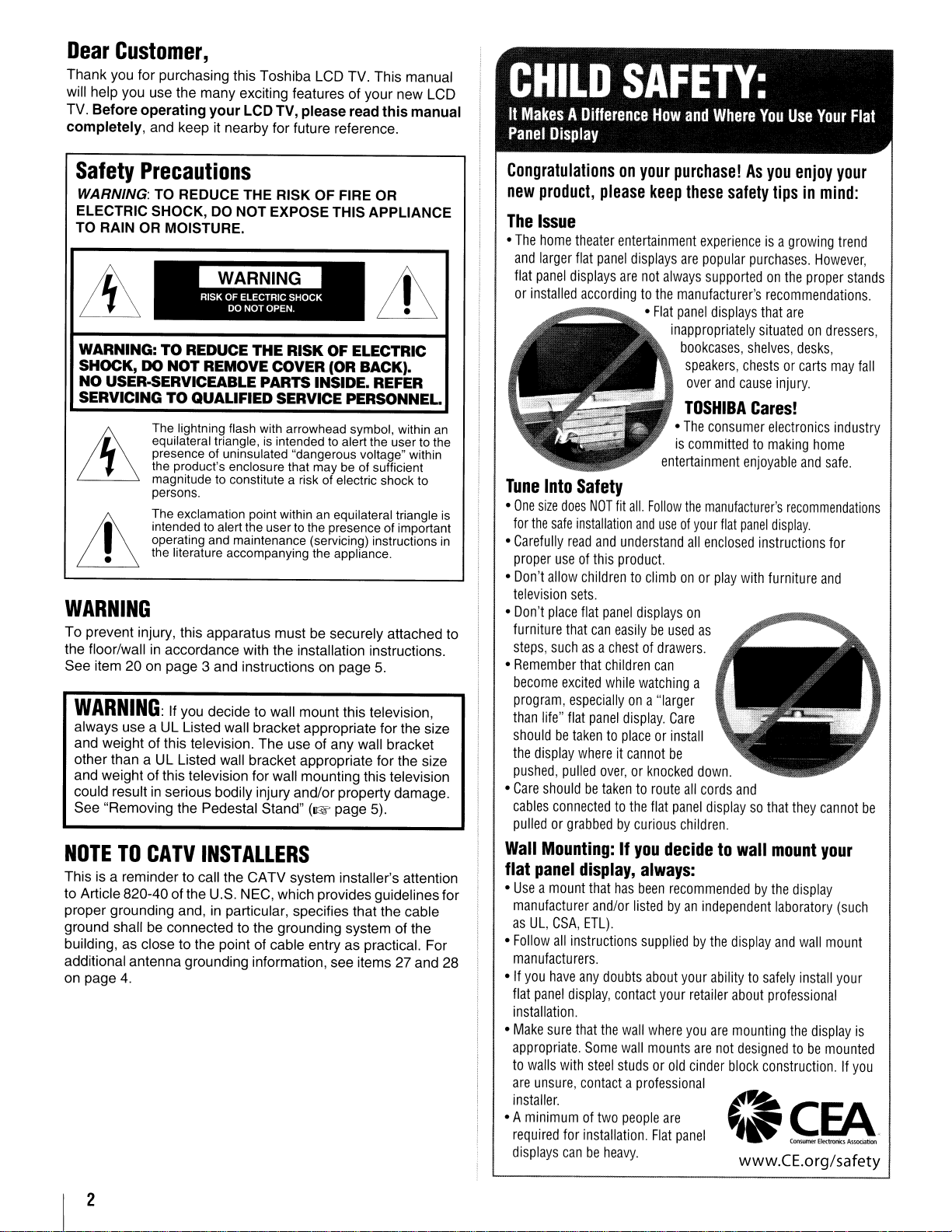
WARNING: TO REDUCE THE RISK OF FIRE OR
ELECTRIC SHOCK, DO NOT EXPOSE THIS APPLIANCE
TO RAIN OR MOISTURE.
WARNING:TOREDUCE
SHOCK, DO
NO
SERVICING TO QUALIFIED SERVICE PERSONNEL.
Precautions
THE
RISK OF ELECTRIC
NOT
REMOVE COVER (OR BACK).
USER-5ERVICEABLE PARTS INSIDE. REFER
The lightning flash with arrowhead symbol, within an
equilateral triangle,
presence of uninsulated "dangerous voltage" within
the product's enclosure that may be of sufficient
magnitude to constitute a risk of electric shock to
persons.
The exclamation point within an equilateral triangle is
intended
operating and maintenance (servicing) instructions
the literature accompanying the appliance.
to
is
intended to alert the user to the
alert the user to the presence of important
WARNING
To prevent injury, this apparatus mustbesecurely attached
the floor/wallinaccordance with the installation instructions.
See
item20on
WARNING:
always
and
weightofthis television.
other than a
and
weightofthis television for wall mounting this television
could result
See "Removing
NOTETOCATV
Thisisa remindertocall
to
Article 820-40 of
proper grounding
ground shall
building,asclose to the pointofcable entryaspractical. For
additional antenna grounding information,
on
page
page 3
useaUL
UL
in
serious bodily injury and/or property damage.
and
If
you
decidetowall
Listed
wall
Listed
wall
the
Pedestal Stand"
instructionsonpage
mount this television,
bracket appropriate for
The
useofany
bracket appropriate for the size
(1kW
page
INSTALLERS
the CATV system installer's attention
the
U.S.
NEC,
which provides guidelines for
and,inparticular, specifies that the cable
be
connected to the grounding system of
see
4.
5.
the
size
wall
bracket
5).
the
items27and
Congratulationsonyour
new
product,
The
Issue
•
The
home
and
larger
flat
panel
or
installed
Tune
Into
•
One
size
for
the
safe
in
to
28
•
Carefully
proper
•
Don't
allow
television
•
Don't
place
furniture
steps,
suchasa
•
Remember
become
program,
than
life"
shouldbetakentoplaceorinstall
the
display
pushed,
•
Care
shouldbetakentoroute
cables
pulledorgrabbedbycurious
Wall
Mounting:Ifyou
flat
panel
•
Useamount
manufacturer
as
UL,
•
Follow
manufacturers.
•Ifyou
have
flat
panel
installation.
•
Make
sure
appropriate.
to
walls
are
unsure,
installer.
• A
minimumoftwo
required
displays
please
theater
entertainment
flat
panel
displays
are
accordingtothe
Safety
does
NOT
fit
installation
read
and
understand
useofthis
sets.
that
excited
especiallyona
flat
pulled
connectedtothe
product.
childrentoclimbonor
flat
panel
can
easilybeused
chestofdrawers.
that
children
while
panel
display.
whereitcannot
over,orknocked
display,
that
has
and/or
CSA,
ETL).
all
instructions
any
doubts
display,
contact
that
the
wall
Some
wall
with
steel
studsorold
contactaprofessional
for
installation.
canbeheavy.
purchase!Asyou
keep
these
displays
are
not
always
manufacturer's
•
Flat
panel
inappropriately
bookcases,
speakers,
over
TOSHIBA
•
The
is
committedtomaking
entertainment
all.
Follow
the
and
useofyour
all
displays
watching
can
"larger
Care
be
flat
on
all
panel
children.
decidetowall
always:
been
recommendedbythe
listedbyan
suppliedbythe
about
your
your
where
you
mounts
people
are
Flat
panel
safety
experienceisa
popular
purchases.
supportedonthe
recommendations
displays
that
situatedondressers,
shelves,
chestsorcarts
and
cause
Cares!
consumer
enjoyable
manufacturer's
flat
panel
enclosed
as
a
down.
cords
displaysothat
independent
retailer
are
cinder
instructions
play
with
and
display
abilitytosafely
about
are
mounting
not
designedtobe
block
www.CE.org/safety
enjoy
your
tipsinmind:
growing
are
injury.
electronics
recommendations
display.
furniture
mount
laboratory
and
professional
construction.Ifyou
However,
proper
desks,
home
and
they
display
wall
install
the
display
trend
stands
may
industry
safe.
for
and
cannot
your
(such
mount
your
mounted
fall
be
is
.
2
Important
1)
Read these
2)
Keep
3)
Heed
4)
Follow
------_._---_
5)
Do
_____________
6)
Clean
________________
7)
Do
accordance with the manufacturer's instructions.
8)
Do
heat registers, stoves, or other apparatus (including
amplifiers) that produce heat.
----
9)
Do
the
plug.
with one widerthan the other.
A grounding type plug has two blades
and a third grounding prong. The wide blade or the third
prong are provided for your safety. If the provided plug
does
replacement
_._.._.._ _.._
10)
Protect
on
convenience receptacles, and the point
where they exit from the apparatus.
11)
Only
manufacturer.
-------------------------
12)
Use
bracket,ortable
manufacturer,orsold
apparatus.
caution when moving the cart/apparatus
combination to avoid injury from tip-over.
Unplug
13)
when
14)
Refer
Servicing is required when the apparatus has been
damaged in
is damaged, liquid has been spilled
into the apparatus, the apparatus has been exposed to
rain
dropped.
Additional
14a)
CAUTION:
enclosure surface has been damaged orthe
operate normally, take the following precautions:
•
ALWAYS
avoid possible electric shock or fire.
• NEVER allow your body to come
• ALWAYS contacta service technician toinspectthe TV
Safety
these
instructions.
all
warnings.
all
instructions.
not
use
this
. .
only
with
._.H._.H_._.
not
block
not
install
not
defeat
polarizedorgrounding
A polarized plug has two blades
not fit into your outlet, consult an electrician for
_.___._._.
_·····.__·_·_···..·__··..·_H····._._····_.·__·•·..··
the
power
or
pinched, particularly at plugs,
use
attachments/accessories
only
with
When a cart is used, use •
this
unused
all
servicingtoqualified
any
or
moisture, does not operate normally, or has been
Safety
If theTVis dropped and the cabinet or
turn off theTVand unplug the power cord to
broken glass
LCD panel inside the
liquid. If the liquid comes
eyes, or your skin is cut
affected area thoroughly with water and consult your
doctor.
any time it has been damaged or dropped.
Instructions
instructions.
...._
..
__
.
apparatus
..
..
dry
·_·
.....
any
ventilation
near
any
the
safety
of
the obsolete outlet.
cord
the
cart,
specifiedbythe
apparatus
for
long
way, such as power-supply cordorplug
near
.
cloth.
_.
heat
purpose
from beingwalked
stand,
with
during
periodsoftime.
water.
~
__
._.
·_·._..._.__
openings.
sources
type
_._
.•.__.•..•.•.•._.•..______
tripod,
the
lightning
service
Precautions
or
liquid from the damaged television. The
TV
contains glass and a toxic
in
contact with your mouth or
by
broken glass, rinse the
r
(
..
.•....
~
-----_
._.._.
.HH._"
. "...
Install in
such as radiators,
of
••••..•...
_ _.._
specifiedbythe
Ci)
1I1
storms
personnel.
or
objects have fallen
in
contact with any
~
TV
~
~
':;;;l
.'
...
_-
...
~
~
..•.••.
_._.._._._._
~
~
~
-
or
does not
15)
CAUTION:
•
To
reduce the risk of electric shock, do not use the
polarized plug with an extension cord, receptacle,
other outlet unless the blades can be inserted
completely to prevent blade exposure.
•
To
prevent electric shock, match wide bladeofplug to
wide slot; fully insert.
_
16)
.
__
WARNING:
To
prevent the spread of fire, keep candles or other open
flames away from this product at all times.
Installation,
Care,
and
Service
Installation
Follow these recommendations and precautions and heed all
warnings when installing your TV:
17) Never modify this equipment. Changes or modifications
may void: a) the warranty, and
operate this equipment underthe rules of the Federal
Communications Commission.
18)
_._
..
Lh
Never place theTVon an unstable cart,
stand, or table. The
serious personal injury, death, or serious
damage to the TV.
19) To avoid damage to this product, never place
TVindirect sunlight; hot, humid areas; or areas subject to
excessive dust
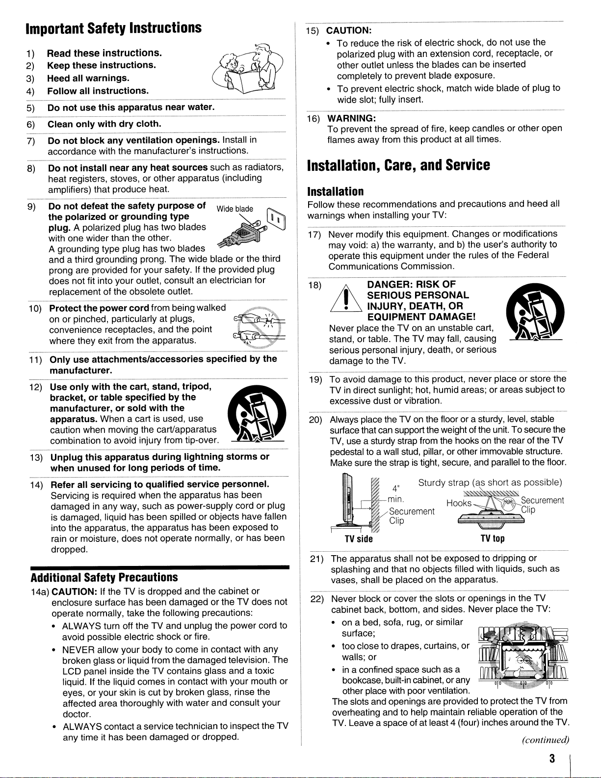
20) Always place the TV on the floor or a sturdy, level, stable
surface that can support the weight of the unit. To securethe
TV, use a sturdy strap from the hooks on the rear ofthe
pedestal to a wall stud, pillar,orother immovable structure.
Make sure the strap is tight, secure, and parallel to the floor.
It
21) The apparatus shall notbeexposed to dripping or
splashing and that no objects filled with liquids, such as
vases, shall be placed on the apparatus.
22) Never block or cover the slots
cabinet back, bottom, and sides. Never place the TV:
• on a bed, sofa, rug, or similar
• too close to drapes, curtains,
•
The slots and openings are providedto protect the
overheating and to help maintain reliable operation of the
TV. Leave a space
DANGER:
I
SERIOUS
•
INJURY,
EQUIPMENT
···.
..
.
"min.
~
TV
side
surface;
walls; or
in
a confined space such as a
bookcase, built-in cabinet,
other place with poor ventilation.
RISK
PERSONAL
DEATH,
TV
may
or
vibration.
4"
Sturdy strap
Securement . L
Clip
of
at least 4 (four) inches around the TV.
b)
the user's authority to
OF
OR
DAMAGE!
fall, causing
(as.s.
hart as possible)
Ho~~~,secu"menl
TV
top
or
openings in the
or
or
any
or
store the
U~Clip
TV
TV
(continued)
or
TV
from
3
23) Always place the back of the television at least four (4)
inches away from any vertical surface (such as a wall) to
allow proper ventilation.
on
24) Neverallow anything to rest
and never place the TV where the power cord is subjectto
wear or abuse.
25) Never overload wall outlets and extension cords.
26) Always operate this equipment from a 120 VAC, 60 Hz
power source only.
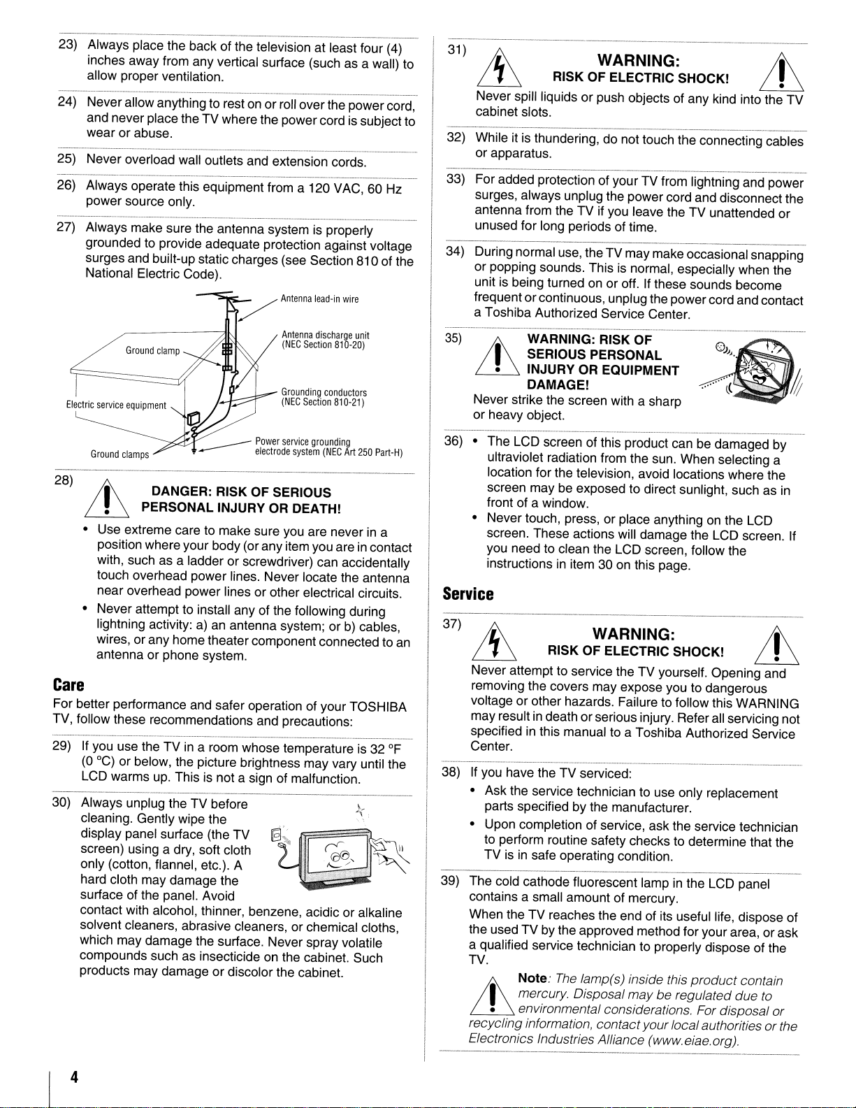
27) Always make sure the antenna system is properly
grounded to provide adequate protection against voltage
surges and built-up static charges (see Section 810 of the
National Electric Code).
Electric
service
equipment
orroll overthe power cord,
Antenna
discharge
(NEG
Section
Grounding
(NEG
Section
unit
810-20)
conductors
810-21)
31
)
RISK OF ELECTRIC SHOCK!
Never spill liquids or push objects of any kind into the TV
cabinet slots.
----_._----_._-_.
is
32) While it
or apparatus.
33) For added protection of your TV from lightning and power
surges, always unplug the power cord and disconnect the
antenna from the TV if you leave the TV unattended or
unused for long periods of time.
34) Duringnormal use, the TV may makeoccasional snapping
or popping sounds. This
unit is being turned on or off. If these sounds become
frequent orcontinuous, unplugthe powercord and contact
a Toshiba Authorized Service Center.
35)
LL
thundering, do nottouch the connecting cables
WARNING: RISK OF
WARNING:
is
normal, especially when the
---_._---
__
..
LL
I SERIOUS PERSONAL
• INJURY OR EQUIPMENT
DAMAGE!
Never strike the screen with a sharp
or heavy object.
___
Power
service
...---
28)
t
~
• Use extreme care to make sure you are never
position where your body (or any item you are
with, such as a ladder or screwdriver) can accidentally
touch overhead power lines. Never locate the antenna
near overhead power lines orother electrical circuits.
• Never attempt to install any of the following during
lightning activity: a)
wires, orany home theater component connected to
antenna or phone system.
DANGER: RISK OF SERIOUS
PERSONAL INJURY OR DEATH!
electrode
an
antenna system; orb)cables,
grounding
system
(NEG
Art
250
in
in
contact
Part-H)
a
Care
For better performance and safer operation of your TOSHIBA
TV, follow these recommendations and precautions:
29) If you use the TVina room whose temperatureis32
(0 0c) or below, the picture brightness may vary until the
is
LCD warms up. This
30) Always unplug the TV before k.
cleaning. Gently wipe the
display panel surface (the TV
screen) using a dry, soft cloth .
only (cotton, flannel, etc.). A
hard cloth may damage the
surface of the panel. Avoid
contact with alcohol, thinner, benzene, acidic oralkaline
solvent cleaners, abrasive cleaners, or chemical cloths,
which may damage the surface. Never spray volatile
compounds such as insecticideonthe cabinet. Such
products may damage or discolor the cabinet.
not a sign of malfunction.
@i~
[ID
~.
'=-.'
,-'
.•
~~
of
~
an
"-
36) • The LCD screen of this product can be damaged by
ultraviolet radiation from the sun. When selecting a
location for the television, avoid locations where the
screen may be exposed to direct sunlight, such as in
front of a window.
on
• Never touch, press, or place anything
screen. These actions will damage the LCD screen. If
you need to clean the LCD screen, follow the
instructionsinitem 30 on this page.
the LCD
Service
37)
RISK OF ELECTRIC SHOCK!
Never attempt to service the TV yourself. Opening and
removing the covers may expose you to dangerous
voltage or other hazards. Failure to follow this WARNING
may result in deathor serious injury. Refer all servicing not
in
specified
Center.
If
you have the TV serviced:
38)
• Ask the service technician to use only replacement
parts specified by the manufacturer.
• Upon completion of service, ask the service technician
to perform routine safety checks to determine that the
TV is
39) The cold cathode fluorescent lampinthe LCD panel
contains a small amount of mercury.
When the TV reaches the end of its useful life, dispose of
the used TVby the approved method for your area, or ask
a qualified service technician to properly dispose of the
TV.
this manual to a Toshiba Authorized Service
in
safe operating condition.
Note:
WARNING:
The
lamp(s) inside this
product
contain
I mercury. Disposal maybe regulated due to
• environmental considerations. For disposal or
LL
recycling information, contactyourlocalauthorities
Electronics Industries Alliance (www.eiae.org).
or
the
4
Choosingalocation
To
Display
your
LCDTVon
for
the
your
LCD
included
TV
Pedestal
Stand:
Observe the following safety precautions:
1) Read and Follow the pedestal assembly instructions included
with the pedestal.
CAUTION: Beforebeginning pedestal assembly, carefully lay
the front
surface such as a quilt
protruding over the edge
pedestal as indicated below.
Note: Extreme care shouldalways beused when attaching
the pedestal stand
2)
Place the TV on a sturdy, level surface that can support the
weight
3)
Be sure to secure the TV to a wall stud, pillar, surface, orother
immovable structure. To secure the TV in this manner: (1)
attach the provided securement clip to an immovable structure,
then (2) pass a sturdy strap through the securement clip and
attach each end to the hooks located on the back
sure to leave at least 4 inches between the TV and the wall or
similar structure for ventilation. See item 20, page 3 for
additional details.
To
Display
If you decide to wall mount your LCD TV, always use a ULlisted wall bracket appropriate for the size and weight of the
LCD TV
1)
CAUTION: Two people are required for installation.
2) Unplug and remove any cables and/or other component
connectors from the rear
3) Follow the instructions provided with your wall bracket.
Before proceeding, make sure the appropriate bracket(s) are
attached to the wall and the back
instructions provided with the wall bracket.
4) After attaching the appropriate bracket(s) to the wall and the
back
described below.
of
the LCD Panel face down on a flat, cushioned
or
blanket. Leave the bottomofthe unit
of
the surface and assemble the
to
avoid damagetothe LCD panel.
of
the TV.
of
your
LCDTVusingaWall
(1& page 2) :
of
the TV.
of
of
the TV, remove the pedestal stand from the TV as
Bracket:
the TV as describedinthe
the TV. Be
Removing
I) Carefully lay the frontofthe unit face down on a flat,
cushioned surface such as a quilt or blanket. Leave the stand
protruding over the edge
Note: Extreme care shouldalways be used when removing
the pedestal stand
2) Remove the jack pack cover on the backofthe TV to expose
the pedestal stand screws. Thejack pack covercan be removed
without tools.
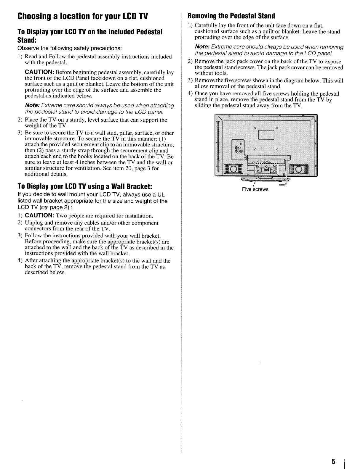
3) Remove thefive screws shown in the diagram below. This will
allow removal
4) Once you have removed all five screws holding the pedestal
stand
sliding the pedestal stand away from the TV.
the
Pedestal
of
the pedestal stand.
in
place, remove the pedestal stand from the TV by
Stand
of
the surface.
to
avoid damagetothe LCD panel.
Five screws
5
FCC
DeclarationofConformity
Important
notes
about
your
LCD
Compliance
(Part
The Toshiba 40XF550U, 46XF550U, and 52XF550U
Televisions comply with Part15of
Operation
device may not cause harmful interference, and (2) this device
must accept any interference received, including interference that
may cause undesired operation.
The party responsible for compliance to these rules is:
Toshiba America Consumer Products,
82 Totowa Rd. Wayne, NJ 07470.
Ph: 1-800-631-3811
Note:
with the limits for
of
the FCC rules. These limits are designedtoprovide
reasonable protection against harmful interference
residential installation.
can radiate radio frequency energy and,ifnot installed
usedinaccordance with the instructions, may cause harmful
interference
no guarantee that interference will not occur
installation. If this equipment does cause harmful interference
to
radio or television reception, which canbedetermined
removing
encouragedtotrytocorrect the interferencebyone ormore
the following measures.
• Reorient or relocate the receiving antenna.
• Increase the separation between the equipment and the
receiver.
• Connect the equipment into
from that to which the receiver
• Consult the dealer
help.
15):
is
subject to the following two conditions: (1) this
This
equipment has been tested
to
radio communications. However, there
and
applying powertothe equipment, the user
Statement
the FCC rules.
L.L.c.
and
foundtocomply
a Class B digital device, pursuant
This
equipment generates, uses,
in
a particular
an
outlet on a circuit different
is
connected.
or
an experienced
radiorrV
technician for
to
Part
in
a
and
and
is
by
is
15
TV
The following symptoms
Display technology
therefore, Toshiba is not responsible for perceived issues
resulting from these symptoms.
I)
An afterimage (ghost) may appear on the screen if a fixed, nonmoving image is displayed for a long period
afterimage is not permanent and will disappear
of
time.
2)
The LCD panel contained in thisTVis manufactured using an
extremely high level
may be an occasional pixel (dot
properly (does not light, remains constantly lit, etc.). This
structural property
malfunction, andisnot covered under your warranty. Such
pixels are not visible when the picture is viewed from a normal
viewing distance.
Note: Interactive video games that involve shooting a "gun"
of
type
TV.
joystick at an on-screen target may not work with this
Trademark
•
wow,
SRS
of
Inc.
WOW
• Manufactured under license from Dolby Laboratories.
Dolby and the double-D symbol are registered trademarks of Dolby
Laboratories.
• HDMI, the HDMIIogo and High-Definition Multimedia Interface are
trademarks or registered trademarks of HDMI Licensing LLC.
• Deep Color
• "x.v.Color" and the "x.v.Color" logo are trademarks of Sony
Corporation.
and ce) symbol are registered trademarks of
technologyisincorporated underlicense from
is
trademark of HDMI Licensing LLC.
are
technical limitations of LCD
and
are
not an indication ofmalfunction;
of
precision technology; however, there
of
light) that does not operate
of
LCD technology,
is
Information
of
time. The
in
a short period
not a sign
SRS
of
SRS
Labs.
Labs, Inc.
is
a
Caution: Changesormodificationstothis equipment not
expresslyapproved
to
operate this equipment.
by
Toshiba could void the user's authority
6
Contents
Important
Installation,
Safety
Care,
Instructions
and
Service
Chapter1:Introduction
Featuresofyour new TV 9
Overview
TV front and side panel controls and connections
TV back panel connections
Chapter2:Connecting
Overviewofcable types
About the connection illustrations
Connecting a VCR (or a VCR with S-video) and antenna,
Connecting a DVD player with ColorStream® (component
Connecting a device to the IR
Connecting an
REGZA-LINK connection
Connecting a digital audio system
Connecting an audio system
Connecting a personal computer (PC)
Chapter3:Using
Preparing the remote control for use 20
Installing the remote control batteries 20
Learning about the remote control
Remote Control functional key chart 22
Using the remote control to operate your other devices 24
Programming the remote control to operate your other
Multi-brand remote control device codes 26
Chapter4:Menu
Main menu layout 33
Setup/Installation menu layout 33
THINe'"
Navigating the menu system 34
of
steps for installing, setting up, and using
your new
TV
your
Cable TV or Camcorder
video), a VCR, and a satellite receiver.
using the IR blaster cable for IR pass-through device
control
HDMI'"
the
remote
devices 24
Device code setup 24
Searching and sampling the codeofa device (8500) 25
Using the volume lock feature (8000)
Operational feature reset (8900) 25
layout
menu
Chapter5:Settingupyour
Setting the Demo Mode 35
Selecting the menu language 35
Configuring the input source for the
ANT/CABLE terminal 36
Programming channels into the
Programming channels automatically 36
Manually adding and deleting channels in the channel
memory 37
Setting the Auto Input feature 37
Labeling channels 38
Setting the HDMI'" audio mode 39
Viewing the digital signal meter. 39
Setting the time zone 39
Viewing the system status
Selecting the Blue LED Illumination level. 40
Selecting the Power-On Mode 40
Selecting the Demo Mode 40
. . . . . . . . . . . . . . . . . . . . . . . . . ...9
10
II
TV
OUT
infrared terminal
or DVI device to the HDMI
control
and
navigation
TV
TV's
channel memory 36
input.
12
12
12
13
14
15
16
17
18
20
21
25
33
33
35
18
19
40
3
3
9
Chapter6:Using
Selecting the video input source to view
Labeling the video input sources
Tuning channels 42
Selecting the picture size 45
Scrolling the TheaterWide® picture
Using the auto aspect ratio feature 47
Using the FREEZE feature 48
Adjusting the picture 48
Using the TheaterLock'" feature 49
Using the closed caption mode 49
Adjusting the audio
Using the Locks menu 52
Using the PC settings feature 56
Setting the PC Audio 57
Setting the sleep timer. 57
Using REGZA-LINK 57
Using the HDMI settings feature 59
Displaying TV status information 60
Understanding the auto power
Understanding the last mode memory feature 60
the
TV's
features
Tuning channels using the Channel Browser'" 42
Setting the Channel Tuning Mode 44
Tuning to the next programmed channel
Tuning to a specific channel (programmed or
unprogrammed) 44
Switching between two channels using Channel
Return 45
Switching between two channels using SurfLock''' 45
(TheaterWide 2 and 3 only) 47
Selecting the picture mode 48
Adjusting the picture quality 48
Base closed captions 49
Digital CC Settings 50
CC Selector
Using the Closed Caption button on the remote
control 50
Muting the sound
Using the digital audio selector
Selecting stereo/SAP broadcasts 5I
Adjusting the audio quality
Using the StableSound® feature 52
Selecting the optical audio output format 52
Using the Dolby® Digital Dynamic Range Control
feature 52
Entering the PIN code 52
If
you cannot remember your PIN code 53
Changing your PIN code 53
Blocking TV programs and movies by rating (V-Chip) 53
Downloading an additional rating system for blocking
TV programs and movies 54
Blocking channels 55
Unlocking programs temporarily 55
Using the input lock feature 55
Using the GameTimer® 55
Using the control panel lock feature 56
REGZA-LINK playback device (HD DVD player, etc.)
control 57
REGZA-LINK input source selection 58
VOLUME and MUTE controls
Other REGZA-LINK functions 58
of
Audio Receiver 58
off
feature 60
41
41
41
44
50
50
50
51
51
(continued)
7
Chapter7:Using
Using the advanced picture settings features
Using the advanced audio settings features 64
the
TV's
advanced
Using dynamic contrast
Using the static gamma feature
Selecting the color temperature
Selecting the cinema mode (480i and 1080i signals) 62
Using the
Using the Film Stabilization feature 62
Using CableClear® digital noise reduction 62
Using MPEG noise reduction
Using the
Using x.v.Color Selection feature 64
Using the Game Mode feature 64
Using the SRS
ClearFrame™
ColorMaster™
WOW®
Chapter8:Troubleshooting
General troubleshooting
LED indications 66
Chapter9:Appendix
Specifications
Acceptable signal formats
for PC IN and HDMI terminals 69
Limited United States Warranty
for LCD Televisions 26" and Larger 70
Limited Canadian Warranty
for Toshiba Brand Flat Panel Televisions
Index
features
feature 62
feature
surround sound feature 64
61
61
61
61
61
63
63
65
65
68
68
71
73
8
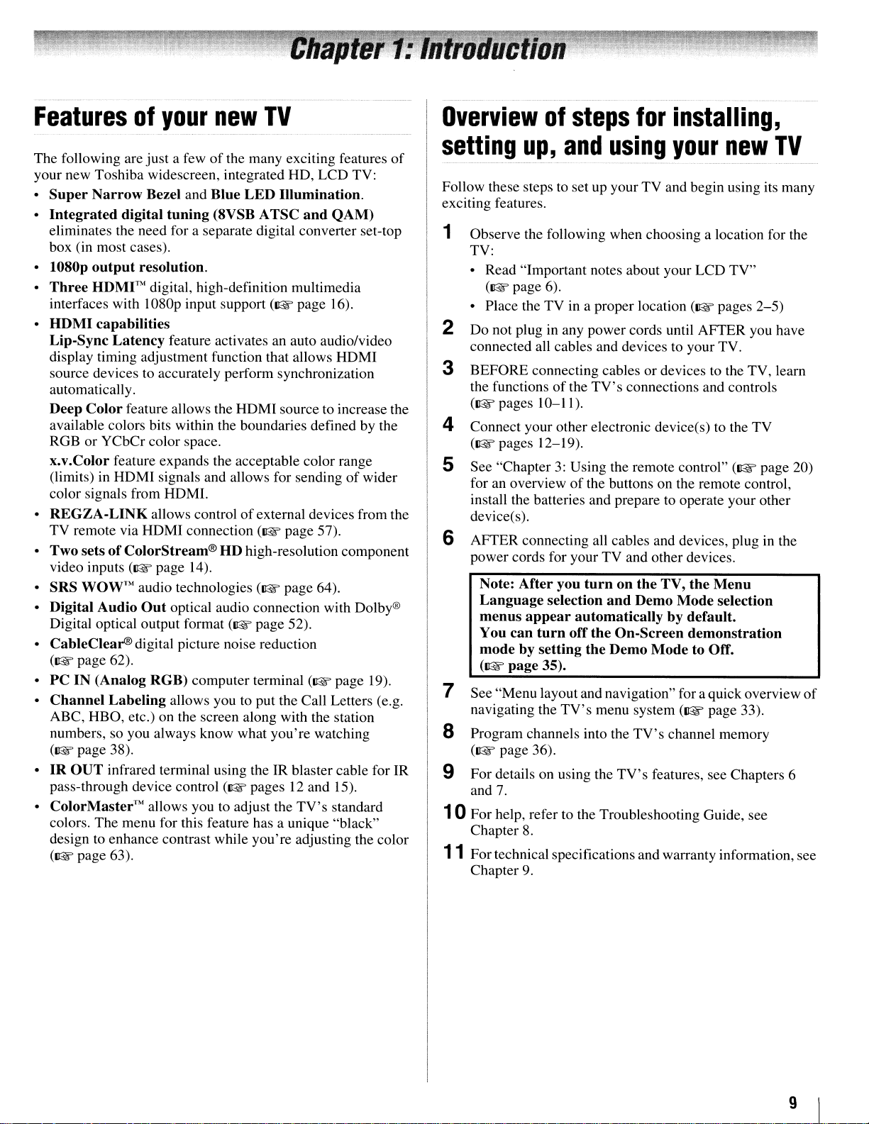
Featuresofyour
new
TV
Overviewofsteps
for
installing,
The following are just a fewofthe many exciting features
your new Toshiba widescreen, integrated RD, LCD TV:
Super
•
•
•
•
•
•
•
• SRS
• Digital Audio
• CableClear®digital picture noise reduction
•
•
•
• ColorMaster™ allows you to adjust the
Narrow
Integrated
eliminates the need for a separate digital converter set-top
box (in most cases).
l080p
output
Three
interfaces with I080p input support
HOM
Lip-Sync
display timing adjustment function that allows HDMI
source devices to accurately perform synchronization
automatically.
Deep
available colors bits within the boundaries defined by the
RGB or YCbCr color space.
x.v.Color feature expands the acceptable color range
TV remote via HDMI connection
HDMI™
I capabilities
Color
(limits) in RDMI signals and allows for sending
color signals from HDMI.
REGZA-LINK
Two
setsofColorStream®HDhigh-resolution component
video inputs
WOW™
Digital optical output format
(~page
PCIN(Analog
Channel
ABC, RBO, etc.) on the screen along with the station
numbers, so you always know what you're watching
(~page
IR
OUT
pass-through device control
colors. The menu for this feature has a unique "black"
design to enhance contrast while you're adjusting the color
(~page
Bezel and Blue
digital
Latency
62).
Labeling
38).
infrared terminal using the IR blaster cable for IR
63).
tuning
resolution.
digital, high-definition multimedia
feature activates an auto audio/video
feature allows the HDMI source to increase the
allows controlofexternal devices from the
(~
page 14).
audio technologies
Out
optical audio connection with Dolby®
RGB)
computer terminal
allows you to put the Call Letters (e.g.
LED
(8VSB A
(~
(~
(~
page 52).
(~pages
Illumination.
TSC
and
QAM)
(~
page 16).
page 57).
page 64).
(~page
12 and 15).
TV's
standard
of
wider
19).
of
setting
Follow these steps to set up your TV and begin using its many
exciting features.
Observe the following when choosing a location for the
1
TV:
• Read "Important notes about your LCD TV"
• Place the TV in a proper location
Do not plug in any power cords until AFTER you have
2
connected all cables and devices to your TV.
BEFORE connecting cables or devices to the TV, learn
3
the functions
([I@f'
Connect your other electronic device(s) to the TV
4
([I@f'
See "Chapter
5
for an overview
install the batteries and prepare to operate your other
device(s).
AFTER connecting all cables and devices, plug
power cords for your TV and other devices.
Note:
Language
menus
You
mode
(~page
up,
(~page
pages 10-11).
pages 12-19).
After
appear
can
turn
by setting
35).
and
6).
of
3:
you
selection
using
the
TV's
connections and controls
Using the remote control"
of
the buttons on the remote control,
turnonthe
and
automaticallybydefault.
off
the
On-Screen
the
Demo
TV,
Demo
Mode
your
(~
the
Mode
demonstration
to Off.
new
pages
([I@f'
Menu
selection
TV
2-5)
page 20)
in
the
7 See "Menu layout and navigation" for aquick overview
navigating the
8 Program channels into the
([I@f'
page 36).
9 For details
and
7.
TV's
on
using the
menu system
TV's
TV's
features, see Chapters 6
([I@f'
page 33).
channel memory
10 For help, refer to the Troubleshooting Guide, see
Chapter
11
Fortechnical specifications and warranty information, see
Chapter
8.
9.
of
9
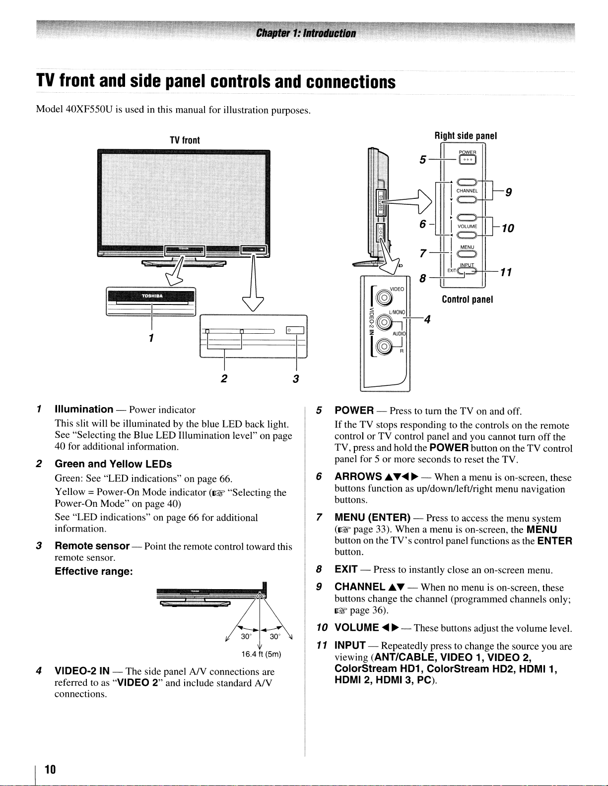
TV
front
Model 40XF550Uisusedinthis manual for illustration purposes.
and
side
panel
TV
front
controls
and
connections
TOSHIBA
I~
1
2
1 Illumination - Power indicator
This slit will be illuminated by the blue LED back light.
See "Selecting the Blue LED Illumination level" on page
40 for additional information.
2 Green and Yellow
Green: See "LED indications" on page 66.
Yellow
Power-On Mode" on page 40)
See "LED indications" on page 66 for additional
information.
3 Remote sensor - Point the remote control toward this
remote sensor.
Effective range:
= Power-On Mode indicator (1tE "Selecting the
LEOs
i
$'
.J'
3
5 POWER - Press
If
the TV stops responding to the controls on the remote
control or TV control panel and you cannot tum offthe
TV, press and hold the
panel for 5 or more seconds to reset the TV.
6 ARROWS
buttons function
buttons.
7
MENU (ENTER) - Press to access the menu system
(1tE page 33). When a menu
button on the
button.
8 EXIT - Press to instantly close
9 CHANNEL.A.T - When
buttons change the channel (programmed channels only;
ItE
page 36).
.A.
T~
TV's
~
as
Control
panel
to
tum the TV on and off.
POWER button on the TV control
- When a menu is on-screen, these
up/down/left/right menu navigation
is
on-screen, the MENU
control panel functionsasthe ENTER
an
on-screen menu.
no
menuison-screen, these
16.4 ft (5m)
4 VIDEO-2IN- The side panel AJV connections are
to
as
referred
connections.
I
10
"VIDEO
2"
and include standard
AN
10
VOLUME
11
INPUT - Repeatedly press to change the source you are
viewing
ColorStream HD1, ColorStream HD2, HDMI1,
HDMI
~ ~
- These buttons adjust the volume level.
(ANT/CABLE, VIDEO1,VIDEO
2,
HDMI 3, PC).
2,
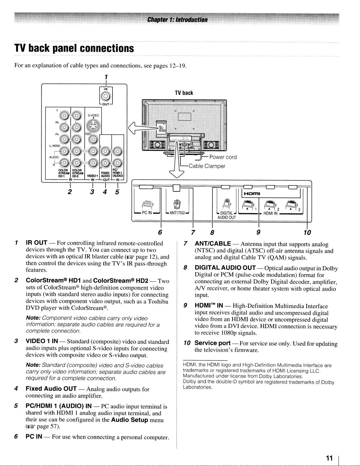
TV
back
For an explanationofcable types and connections, see pages 12-19.
panel
connections
TV
back
6
1 IR
2 ColorStream®
3 VIDEO 1 IN - Standard (composite) video and standard
4 Fixed Audio
OUT
- For controlling infrared remote-controlled
devices through the TV. You can connect up to two
devices with an optical IR blaster cable
then control the devices using the
features.
HD1
and ColorStream® HD2 - Two
of
sets
inputs (with standard stereo audio inputs) for connecting
devices with component video output, such as a Toshiba
DVD player with ColorStream®.
Note: Component video cables carry only video
information; separate audio cables are required for
complete connection.
audio inputs plus optional S-video inputs for connecting
devices with composite video or S-video output.
Note: Standard(composite) video
carry only video information; separate audio cables are
required for a complete connection.
connecting an audio amplifier.
ColorStream® high-definition component video
OUT
- Analog audio outputs for
(~page
TV's
IR pass-through
and
S-video cables
12), and
a
i:Jml
~
M
l
DIGITAL
AUDIO
7
7 ANT/CABLE - Antenna input that supports analog
8 DIGITAL AUDIO OUT - Optical audio output in Dolby
9
10 Service port - For service use only. Used for updating
HDMI, the HDMIIogo and High-Definition Multimedia Interface are
trademarks or registered trademarks of HDMI Licensing LLC.
Manufactured under license from Dolby Laboratories.
Dolby and the double-D symbol are registered trademarks of Dolby
Laboratories.
8
(NTSC) and digital (A TSC) off-air antenna signals and
analog and digital Cable TV (QAM) signals.
Digital or PCM (pulse-code modulation) format for
connecting an external Dolby Digital decoder, amplifier,
A/V receiver, or home theater system with optical audio
input.
HDMrMIN - High-Definition Multimedia Interface
input receives digital audio and uncompressed digital
video from an HDMI device or uncompressed digital
video from a DVI device. HDMI connection is necessary
to receive I080p signals.
the television's firmware.
~ ~ ~
~1
j~
OUT
-
9 10
~2
HDMIIN
~
~3
5
PC/HDMI1
shared with HDMI I analog audio input terminal, and
their use can be configured in the Audio Setup menu
(~page
6 PC IN - For use when connecting a personal computer.
(AUDIO) IN - PC audio input terminal is
57).
11
I
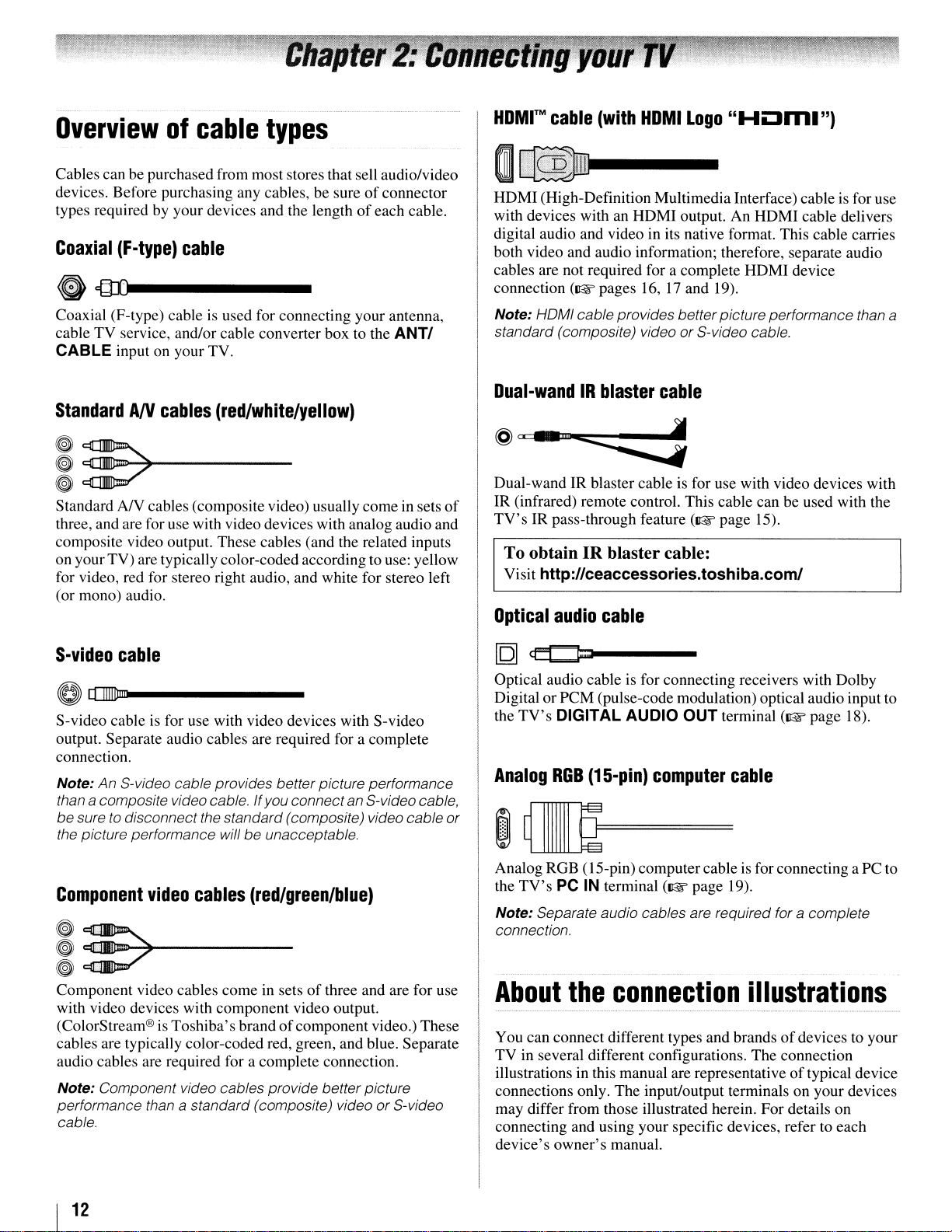
Overviewofcable
Cables can be purchased from most stores that sell audio/video
devices. Before purchasing any cables, be sureofconnector
types required by your devices and the lengthofeach cable.
Coaxial
(F-type)
cable
types
@){Ul-----
Coaxial (F-type) cableisused for connecting your antenna,
cable TV service, and/or cable converter box to the
CABLE input on your TV.
ANTI
HDMrMcable
HDMI
with devices with an
digital audio and video in its native format. This cable carries
both video and audio information; therefore, separate audio
cables are not required for a complete
connection
(High-Definition Multimedia Interface) cable is for use
Note: HOMI cable provides betterpicture performance than a
standard (composite) video or S-video cable.
(with
HDMI
(~pages
HOM
I
Logo
output.
16,17and 19).
"HOm.")
An
HDMI
HDMI
cable delivers
device
StandardANcables
~::7
~
~
Standard
three, and are for use with video devices with analog audio and
composite video output. These cables (and the related inputs
on your TV) are typically color-coded according to use: yellow
for video, red for stereo right audio, and white for stereo left
(or mono) audio.
S-video
S-video cable is for use with video devices with S-video
output. Separate audio cables are required for a complete
connection.
Note: An S-video cable provides better picture performance
than
be sure
the picture performance will be unacceptable.
-~-----
AN
cables (composite video) usually comein sets
cable
a composite video cable. If you connect an S-videocable,
to
disconnect the standard (composite) video cable
(red/white/yellow)
of
or
Dual-wandIRblaster
@"
_"n
....
:::::::
Dual-wandIRblaster cable is for use with video devices with
IR
(infrared) remote control. This cable can be used with the
TV'sIRpass-through feature
To obtain IR blaster cable:
Visit http://ceaccessories.toshiba.com/
Optical
Optical audio cable is for connecting receivers with Dolby
Digital or PCM (pulse-code modulation) optical audio inputto
the
Analog
audio
TV's
DIGITAL AUDIO
RGB
(15-pin)
cable
cable
j
(~page
OUT
terminal
computer
15).
cable
(~page
18).
Component
i
!:>"""-+-----
Component video cables come in setsofthree and are for use
with video devices with component video output.
(ColorStream®isToshiba's brandofcomponent video.) These
cables are typically color-coded red, green, and blue. Separate
audio cables are required for a complete connection.
Note: Component video cables provide betterpicture
performance than
cable.
I
12
video
cables
a standard (composite) video or S-video
(red/green/blue)
Analog RGB (IS-pin) computercable is for connecting aPC to
the
TV's
PC IN terminal
Note: Separate audio cables are required for a complete
connection.
About
You can connect different types and brandsofdevices to your
TV in several different configurations. The connection
illustrationsinthis manual are representative oftypical device
connections only. The input/output terminals on your devices
may differ from those illustrated herein. For details on
connecting and using your specific devices, refer to each
device's owner's manual.
the
connection
(~page
19).
illustrations
.
__
. _
..__.
__
_
..
_ _
..
_
..
_..
'._
- _.. -
-----
.
__
.-
.
_.-
ConnectingaVCR
Camcorder
Camcorder
AUDIO
VIDEO
OUT
L~
~
l
R!iJJ_l
-fr-
~
VIDEO2inputs
onTVright
L....:c:::at:ll=>7~
side
panel
I
r~'DEO
-"-"""'"--~~
,_".......~L!.~UD'f
L~R
(oraVCR
TV
upper
r;Jl~~
L
PC
IN
back
with
panel
ANT<75Q)
S-video)
and
IDl-----------....I
antenna,
Stereo
VCR
V'DEO
o
~
&L,
Cable
AUDI
~
~I,"
,_,~"'
TV
From
CableTVor
g~:~,",,,mA"T@)
DUTloTV
or
antenna
~
~~
,
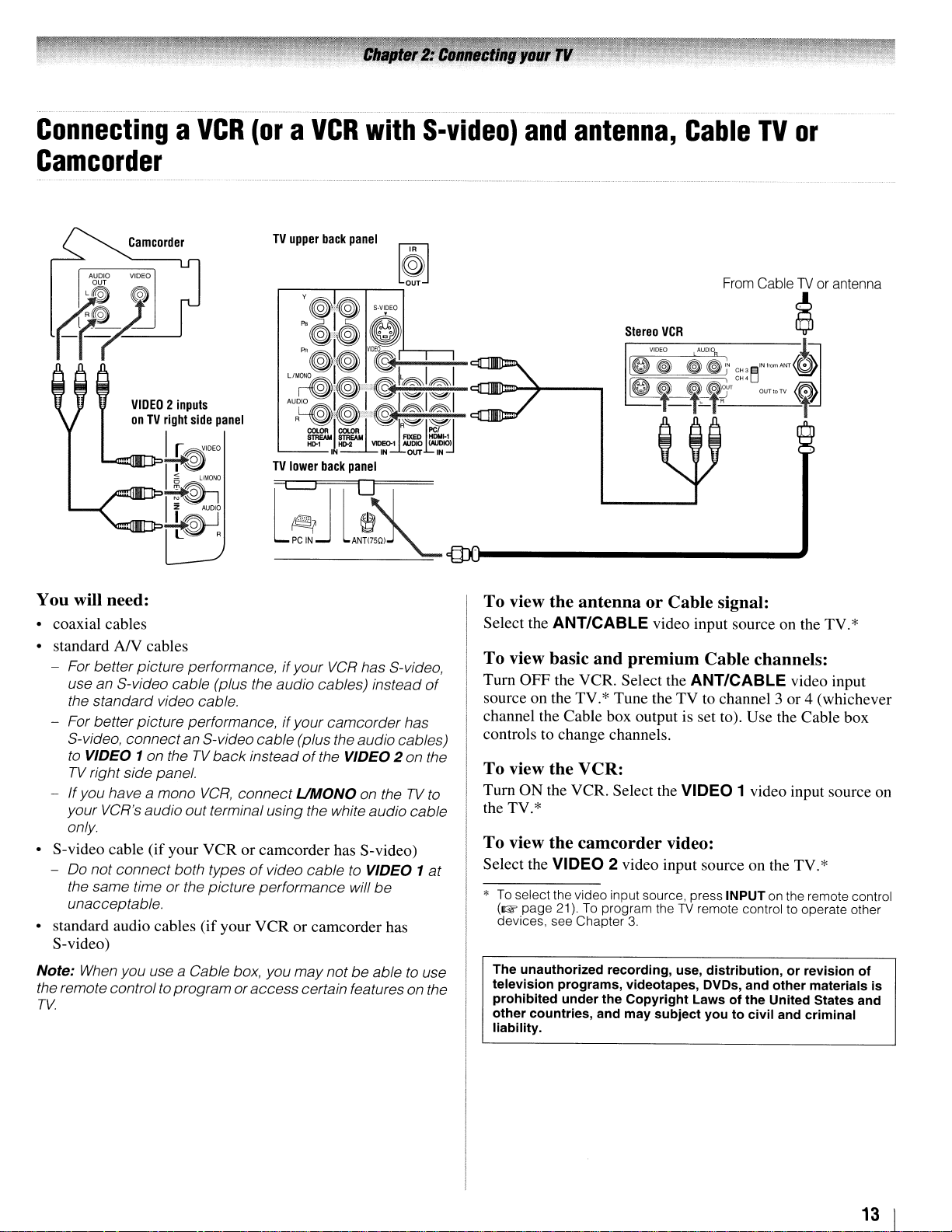
You will need:
• coaxial cables
NY
• standard
- For betterpicture performance,ifyour
use an S-video cable (plus the audio cables) instead
the standard video cable.
- For better picture performance,
S-video, connectan S-videocable (plus the audio cables)
to VIDEO
TV
right side panel.
- If you have a mono
your VCR's audio out terminal using the white audio cable
only
• S-video cable (ifyour VCR or camcorder has S-video)
-
00
not connect both typesofvideo cable to VIDEO 1
the same timeorthe picture performance will be
unacceptable.
• standard audio cables (if your VCR or camcorder has
S-video)
Note:
When
the remote controlto programor
TV.
cables
VCR
has S-video,
if
your camcorder has
1 on the
you use a Cable box, you may not be able to use
TV
VCR,
back
insteadofthe VIDEO 2 on the
connect
access
UMONO
certain features on the
on theTVto
of
at
To
view
the
antennaorCable
Select the ANT/CABLE video input source on the TV.*
To
view basic
Turn OFF the VCR. Select the ANT/CABLE video input
source on the TV.* Tune the TV to channel 3 or 4 (whichever
channel the Cable box output is set to). Use the Cable box
controls to change channels.
To
view
Turn
ON
the TV.*
To
view the
Select the VIDEO 2 video input source on the TV.*
* To select the video input source, press INPUT on the remote control
(~
page 21).Toprogram theTVremote control to operate other
devices, see Chapter
The
unauthorized
television
prohibited
other
countries,
liability.
and
premium
the
VCR:
the VCR. Select the VIDEO 1 video input source on
camcorder
under
recording,
the
and
programs,
video:
3.
videotapes, DVDs, and
Copyright
may
SUbject
signal:
Cable channels:
use,
distribution,orrevision
Lawsofthe
youtocivil
other
United States and
and
materials
criminal
of
is
13
I
............•........•..•
_ _............... .
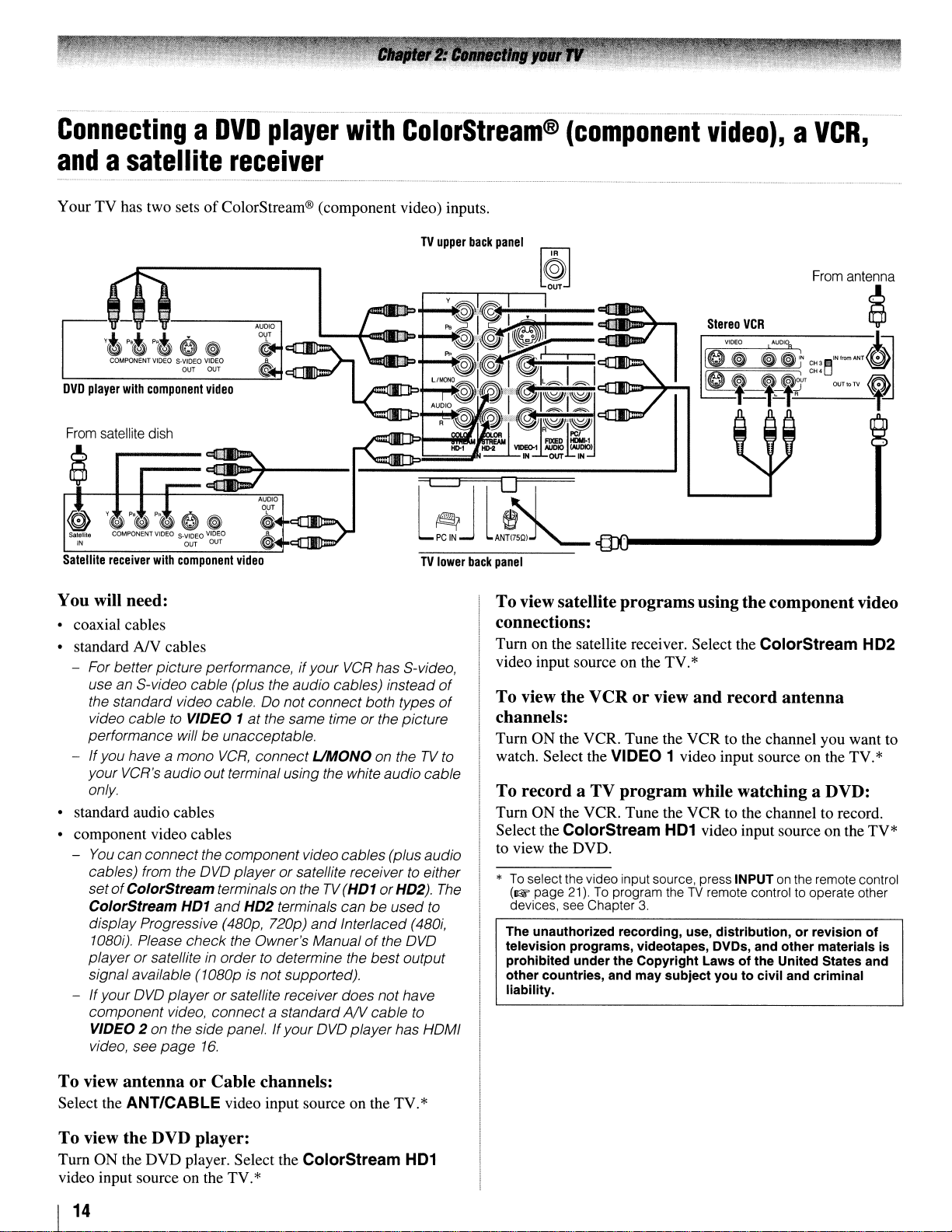
ConnectingaDVD
andasatellite
YourTVhas two setsofColorStream® (component video) inputs.
From
satellite
dish
player
receiver
with
ColorStream®
~
AUDIO
o,ur
Satellite
receiver
with
component
~
~
video
---
........,....,-.r
TV
lower
back
panel
(component
video),aVCR,
You will need:
• coaxial cables
• standard
- For betterpicture performance,ifyour
-
• standard audio cables
• component video cables
-
- Ifyour
NY
cables
VCR
has S-video,
use an S-video cable (plus the audio cables) instead
the standard video cable.00not connect both types
video cabletoVIDEO 1atthe same time or the picture
performance willbeunacceptable.
If
you have a mono
your VCR's audio out terminal using the white audio cable
only
You
can connect the componentvideo cables (plus audio
cables) from the
setofColorStream terminals on theTV(HD1 orHD2).
ColorStream HD1
display Progressive (480p, 720p)
1080i). Please check the Owner's Manualofthe
player or satelliteinordertodetermine the bestoutput
signal available (1080pisnot supported).
OVO
player or satellite receiver does nothave
component video, connect a standardANcable
VIDEO 2 on the side panel. Ifyour
video, see
page
VCR,
connect
OVO
player or satellite receivertoeither
and
HD2 terminals canbeused
16.
UMONO
and
Interlaced (480i,
OVO
playerhas HOMI
on theTVto
OVO
to
to
of
of
The
To view satellite programs usingthe component video
connections:
Turn on the satellite receiver. Select the ColorStream HD2
video input source on the TV.*
To view the VCR or view and record antenna
channels:
Turn ON the VCR. Tune the VCR to the channel you want to
watch. Select the VIDEO 1 video input source on the TV.*
To record a TV program while watching a DVD:
Turn ON the VCR. Tune the VCR to the channel to record.
Select the ColorStream
to view the DVD.
*
To
select the video input source, press INPUT on the remote control
(~ page 21).
devices, see Chapter 3
The unauthorized recording, use, distribution, or revision of
television programs, videotapes, DVDs, and other materials is
prohibited underthe Copyright Laws of the United States and
other countries, and may SUbject you to civil and criminal
liability.
To
program theTVremote control to operate other
HD1
video input source on the TV*
To view antenna or Cable channels:
Select the ANT/CABLE video input source on the TV.*
To view the DVD player:
Turn ON the DVD player. Select the ColorStream
video input source on the TV.*
I
14
HD1
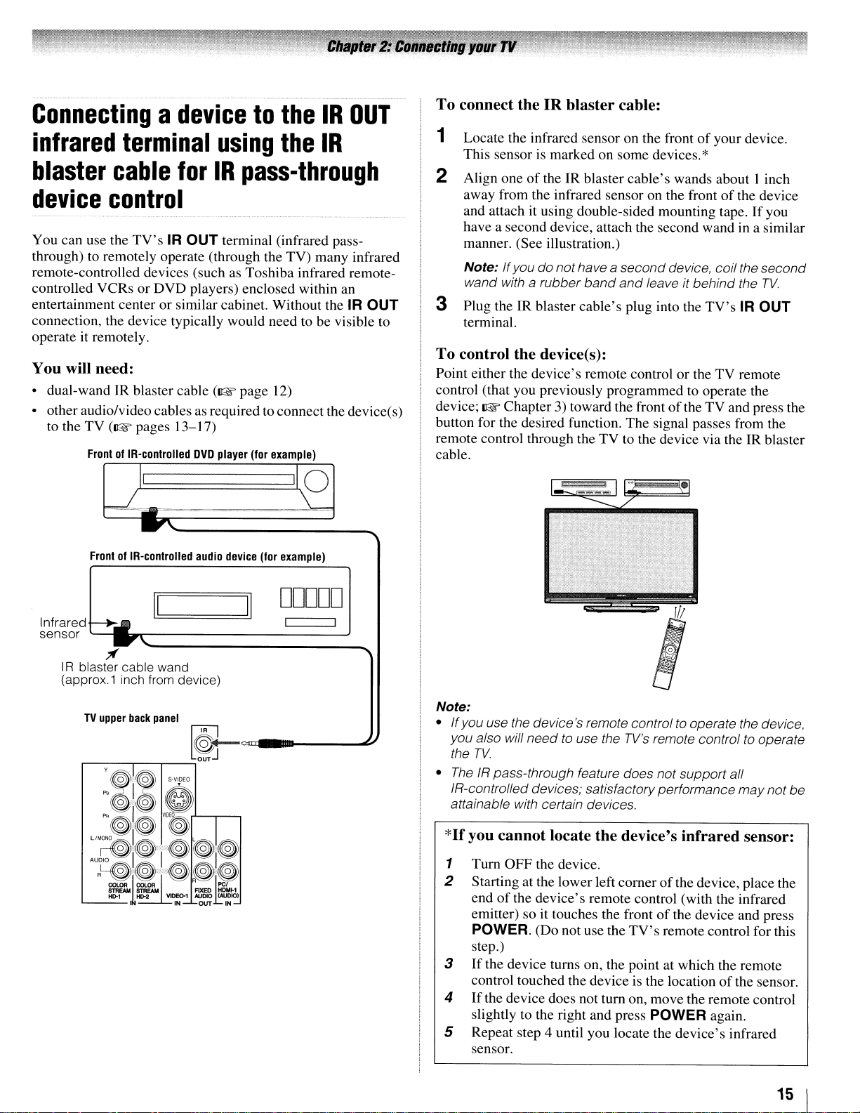
Connectingadevicetothe
infrared
blaster
device
You can use the through) to remotely operate (through the TV) many infrared remote-controlled devices (such controlled VCRs or DVD players) enclosed within an entertainment center or similar cabinet. Without the IR OUT connection, the device typically would need to be visible to operate it remotely.
You will need:
• dual-wand IR blaster cable (lIE page
• other audio/video cablesasrequired to connectthe device(s)
to the TV (lIE pages
terminal
cable
for
control
TV'sIROUT
13-17)
FrontofIR-controlled
using
IR
pass-through
terminal (infrared pass-
as
Toshiba infrared remote-
12)
DVD
player
(for
example)
the
IR
IR
OUT
To
connect the IR blaster cable:
1 Locate the infrared sensor on the front
This sensor is marked on some devices.
2 Align one
away from the infrared sensor on the front
and attach it using double-sided mounting tape.
have a second device, attach the second wand
manner. (See illustration.)
Note:
wand with a rubber
3 Plug the
terminal.
To
control the device(s):
Point either the device's remote control or the TV remote
control (that you previously programmed to operate the
device; lIE Chapter
button for the desired function. The signal passes from the
remote control through the TV to the device via the
cable.
of
theIRblaster cable's wands about I inch
If
you do nothave a
IR
blaster cable's plug into the
3)
toward the frontofthe TV and press the
band
second
and
leave it
of
your device.
*
of
the device
in
device, coil the
behind
the
TV'sIROUT
If
you
a similar
second
TV.
IR
blaster
):=================~I
FrontofIR-controlled
Infraredr-~
sensor
TV
,....-
/f
upper
__
IR blaster cable wand
(approx.1 inch from device)
I!=I
I.
......
-------------'
back
panel
~--,_-,ouTJ
audio
device
==:!.JII
[@J
<=11"--~
0
(for
example)
DDDDD
Note:
• Ifyou use the device's remote controlto operate the device,
need
you also will
the
TV.
•
The
IR pass-through feature does not support all
IR-controlled devices; satisfactoryperformance
attainable with certain devices.
*If
you cannot locate the device's infrared sensor:
1 Turn OFF the device.
2 Starting at the lower left corner
of
the device's remote control (with the infrared
end
emitter) so it touches the front
POWER. (Do not use the
step.)
3
If
the device turns on, the point at which the remote
control touched the device is the location
4
If
the device does not turn on, move the remote control
slightly
5 Repeat step 4 until you locate the device's infrared
sensor.
to use the
to
the right and press POWER again.
TV's
remote control to operate
of
the device, place the
of
the device and press
TV's
remote control for this
of
the sensor.
may
not
be
15 1
Connecting
to
the
HDMI
The HDMI input on your TV receives digital audio and
uncompressed digital video from an HDMI source device,
uncompressed digital video from a DVI (Digital Visual
Interface) source device.
This inputisdesigned to accept HDCP (High-Bandwidth
Digital-Content Protection) program material in digital form
from EIA/CEA-861-D--compliant[11 consumer electronic
devices (suchasa set-top boxorDVD player with HDMI or
DVI output).
The HDMI input can accept and display VGA, SVGA, XGA,
WXGA, SXGA, 480i (60Hz), 480p (60Hz),
1080i (60Hz), and 1080p (24Hz/60Hz) signal formats. For
detailed signal specifications, see page 69.
Supported Audio format: Linear PCM, sampling rate 32/44.1/
48kHz
Note:
•
To
connect a PCtothe
• Someoflegacy
your latest
trytoset
Deep Color, x.v.Color).
operate properly with your
• Supported Audio format· Linear
44.1/48kHz
HoMI
Off
an
HDMI™orDVI
device
input
or
nop
(60Hz),
HoMI
input, see
HoMI
sources may not work properly with
TV,
duetonew standardadoption. Please
the following three options (Lip-Sync Latency,
Your
legacy
TV.
See
PCM,
page
HoMI
source should
page
69.
sampling rate
19.
32/
*
To
select the video input source, press INPUT on the remote control
(~
page 21).Toprogram theTVremote control to operate other
devices, see Chapter
3.
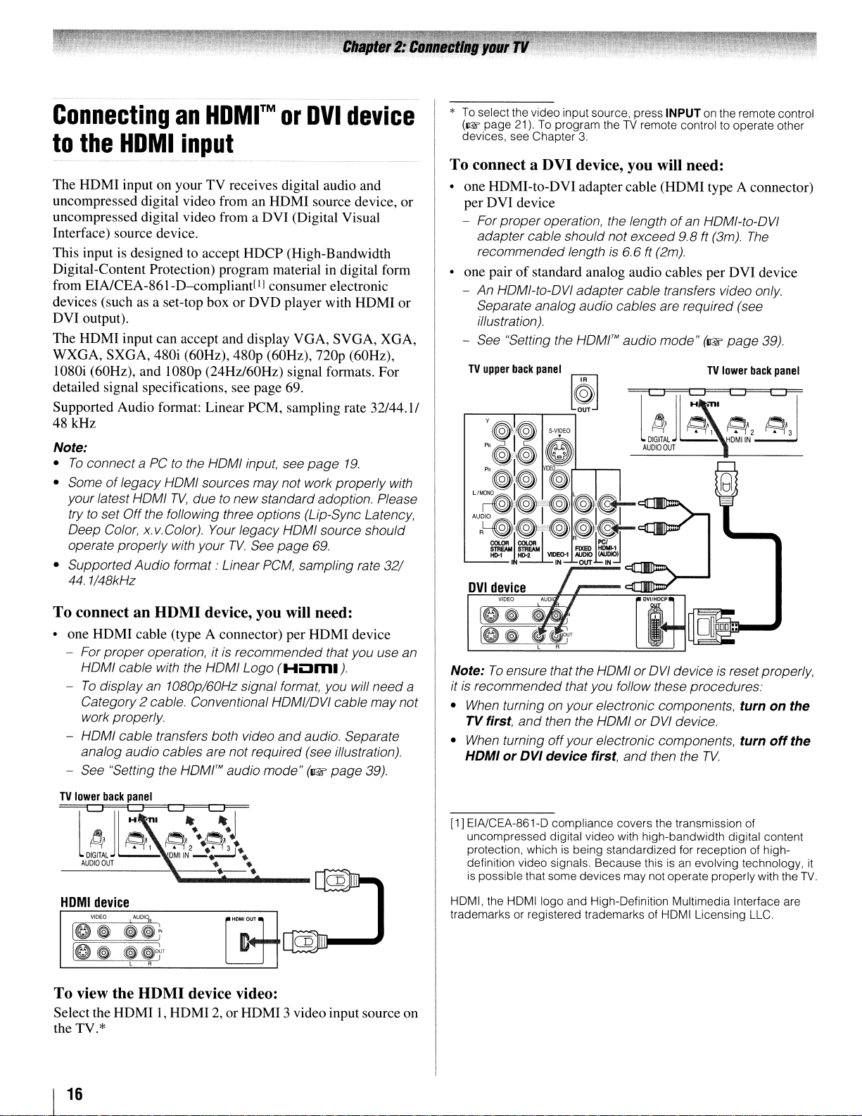
To connect a DVI device, you will need:
• one HDMI-to-DVI adapter cable (HDMI type A connector)
per DVI device
- For proper operation, the lengthofan HOMI-to-OVI
adapter cable should notexceed 9.8 ft (3m).
recommended length
• one pairofstandard analog audio cables per DVI device
- An HOMI-to-OVI adapter cable transfers video only.
Separate analog audio cables are required (see
illustration).
- See "Setting the
TV
upper
back
panel
,...---r----,---,
HOMI'M
~
is
6.6
ft
(2m).
audio mode"(~page
LJ
j~~
~
DIGITAL
OUT
~,
l
AUDIO
TV
ml
The
39),
lower
back
panel
LJ
~LJ?
~2
~3
DMIIN
To connect an HDMI device, you will need:
one HDMI cable (type A connector) per HDMI device
- For properoperation, itisrecommended that you use an
HoMI
cable with the
To
display an 1080p/60Hz signal format, you will need a
Category2 cable. Conventional
work properly.
HOMI cable transfers both video
analog audio cables are not required (see illustration).
See "Setting the
TV
lower
back
panel
LJ
j~~-
4
DIGITAL
OUT
~1
l
AUDIO
HoMI
Logo
(HOm.).
HoMI/oVI
and
audio. Separate
HOMI™
audio mode"
(~page
c:q=
~2··~:.
'DMIIN
--;..:..::.J
••
• •
cable may not
39).
--.-.
HOMI
device
VIDEO1"00%
IO~
[0
To view the
Select the HDMI1,HDMI2,or HDMI 3 video input source on
the TV.*
~~t
~
~jOf
L R
HDMI
"'HOM'
OUT.
device video:
Note:
To
ensure that the HOMI or
itisrecommended that you follow these procedures.'
•
When
turning on yourelectronic components,
TV first,
•
When
HDMIorDVI device first,
[1] EIA/CEA-861-D compliance covers the transmission of
un
protection, which
definition video signals. Because this
is possiblethat some devices may not operate properlywith the
HDMI, the
trademarks or registered trademarks of HDMI Licensing LLC.
and
then the HOMI or
turning
compressed digital video with high-bandwidth digital content
off
HDMIIogo
your electronic components,
is
being standardized for reception of high-
and High-Definition Multimedia Interface are
and
oVI
deviceisreset properly,
turnonthe
oVI
device.
turn
then the
TV.
isanevolving technology,
off
the
it
TV.
I
16
REGZA·LINK
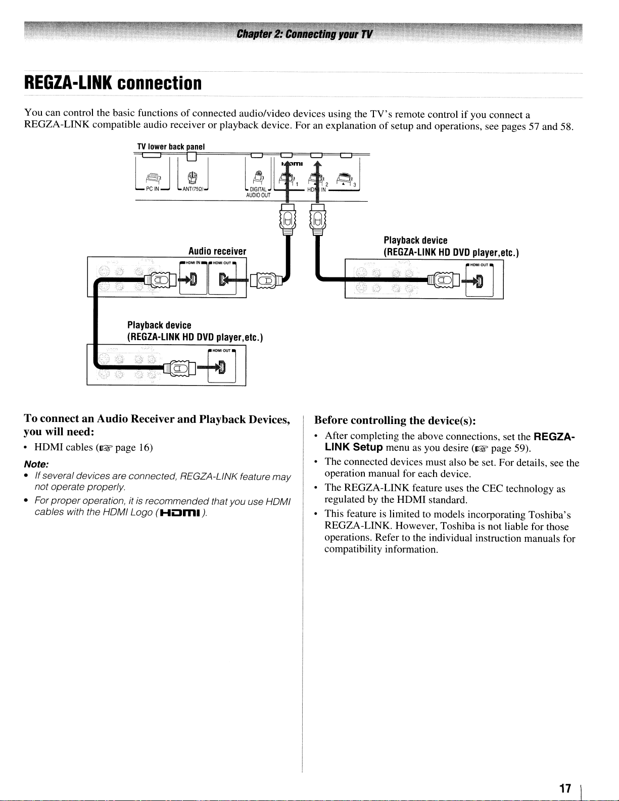
connection
You can control the basic functionsofconnected audio/video devices using the
REGZA-LINK compatible audio receiver or playback device. For an explanation
TV
lower
back
panel
~l~J
PC
l~
IN
ANTI75QI
J
'-+~~~~llfl~
TV's
remote controlifyou connect a
of
setup and operations, see pages 57 and 58.
Playback
(REGZA-L1NKHDDVD
device
player,
etc.)
g)g]fm-]
To connect an Audio Receiver and Playback Devices,
you will need:
•
HOM
I cables
Note:
• If several devices are connected, REGZA-LINK feature may
not operate properly.
• For
proper
cables with the HOMI Logo
(I@"
page 16)
operation, it is recommended thatyou use HOMI
(HLlml).
Before controlling the device(s):
• After completing the above connections, set the REGZA-
LINK Setup
• The connected devices must also be set. For details, see the
operation manual for each device.
• The REGZA-LINK feature uses the CEC technology
regulatedbythe
• This feature is limited
REGZA-LINK. However, Toshiba
operations. Refer to the individual instruction manuals for
compatibility information.
menu as you desire
HOMI
standard.
to
models incorporating Toshiba's
(I@"
page 59).
is
not liable for those
as
11
\
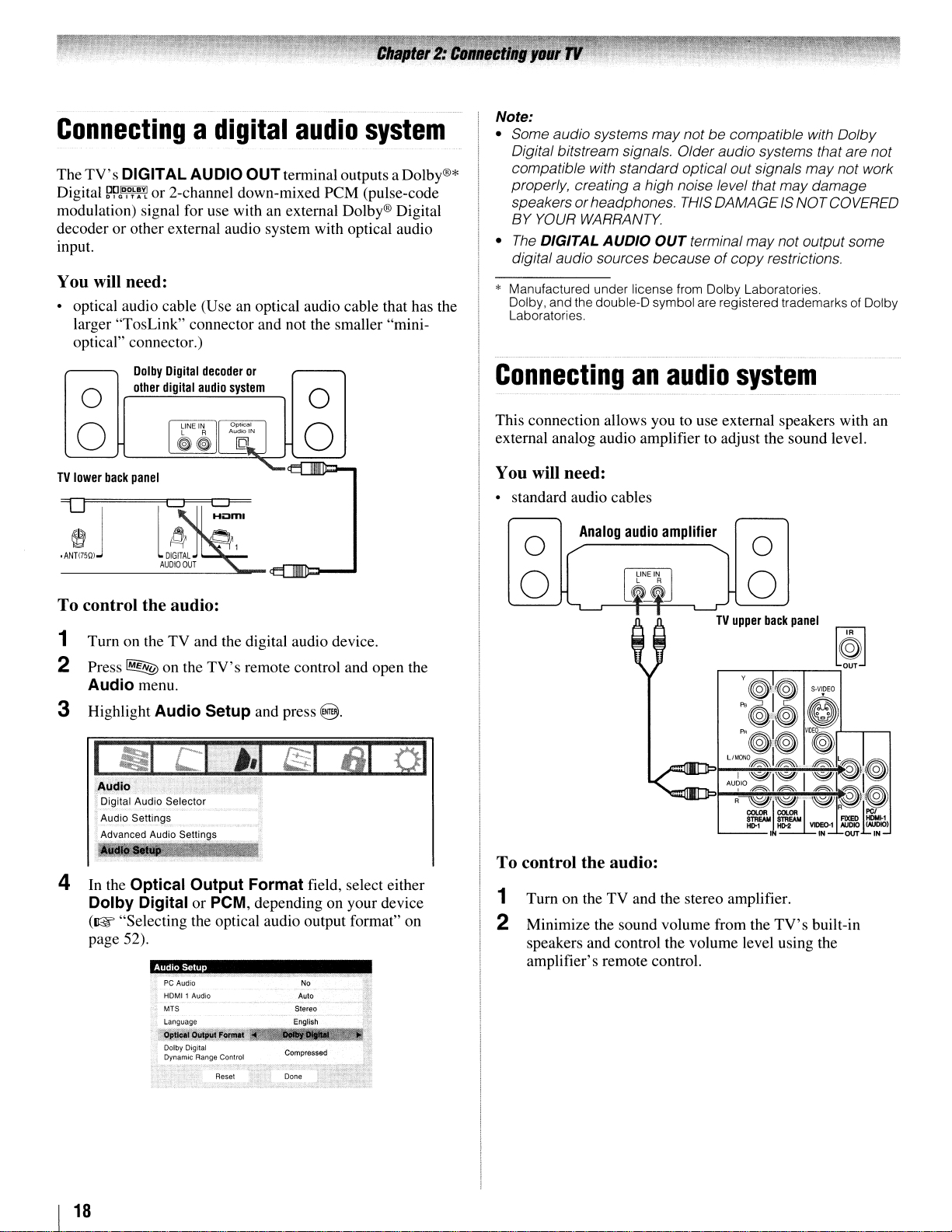
Connectingadigital
The
TV's
DIGITAL
Digital
modulation) signal for use with an external Dolby® Digital
decoderorother external audio system with optical audio
input.
You
• optical audio cable (Useanoptical audio cable that has the
~~D,D~~Y!
will need:
larger "TosLink" connector and not the smaller "minioptical" connector.)
Dolby
other
AU
010
OUTterminal outputs a Dolby®*
or 2-channel down-mixed
Digital
decoder
or
digital
audio
system
o
o
audio
peM
o
o
system
(pulse-code
Note:
• Some audio systems maynotbecompatible with Dolby
Digital bitstream signals. Older audio systems thatare
compatible with standard optical out signals
properly, creating
speakers
BY
•
The
digital audio sources becauseofcopy
* Manufactured under license from Dolby Laboratories.
Dolby, and the double-Dsymbol are registered trademarks of Dolby
Laboratories.
or
YOUR
DIGITAL
WARRANTY.
Connecting
This connection allows you to use external speakers with an
external analog audio amplifier to adjust the sound level.
a high noise level that may damage
headphones.
AUDIO
an
THIS
OUT
terminal
audio
DAMAGEISNOT COVERED
may
system
may
not output some
restrictions.
not
not work
TV
lower
back
panel
To control the audio:
1 Turn on the TV and the digital audio device.
2 Press
3 Highlight
4 In the Optical
~
on the
TV's
remote control and open the
Audio
Dolby
(I@' "Selecting the optical audio output format" on
page 52).
menu.
Audio
Digital or PCM, depending on your device
Audio Setup
Setup and press
Output
PC
Audio No
HOMI1 Audio
MTS Stereo
language
Format field, select either
Auto
English
8.
You will need:
• standard audio cables
Analog
audio
amplifier
o
o
o
o
,....---r---r---=;
:
~.i.:~
e;~
PR
Ol~
LlMaNO
I l
I
~I"~""I""~I~:I"~
AU~IO~~
R~l"'~I:G~"'~~~~"~
STREAM
ttr1
L...-
__
I
To control the audio:
1 Turn on the TV and the stereo amplifier.
2 Minimize the sound volume from the
speakers and control the volume level using the
amplifier's remote control.
[@]
S·V'OEO
V1D~r'--r---'
~~.~
STREAM
HD-2
TV's
F1XEO
VI>EO-1
AUDIO
IN
built-in
OUT
HOM!-1
(NJDIO)
IN
I
18
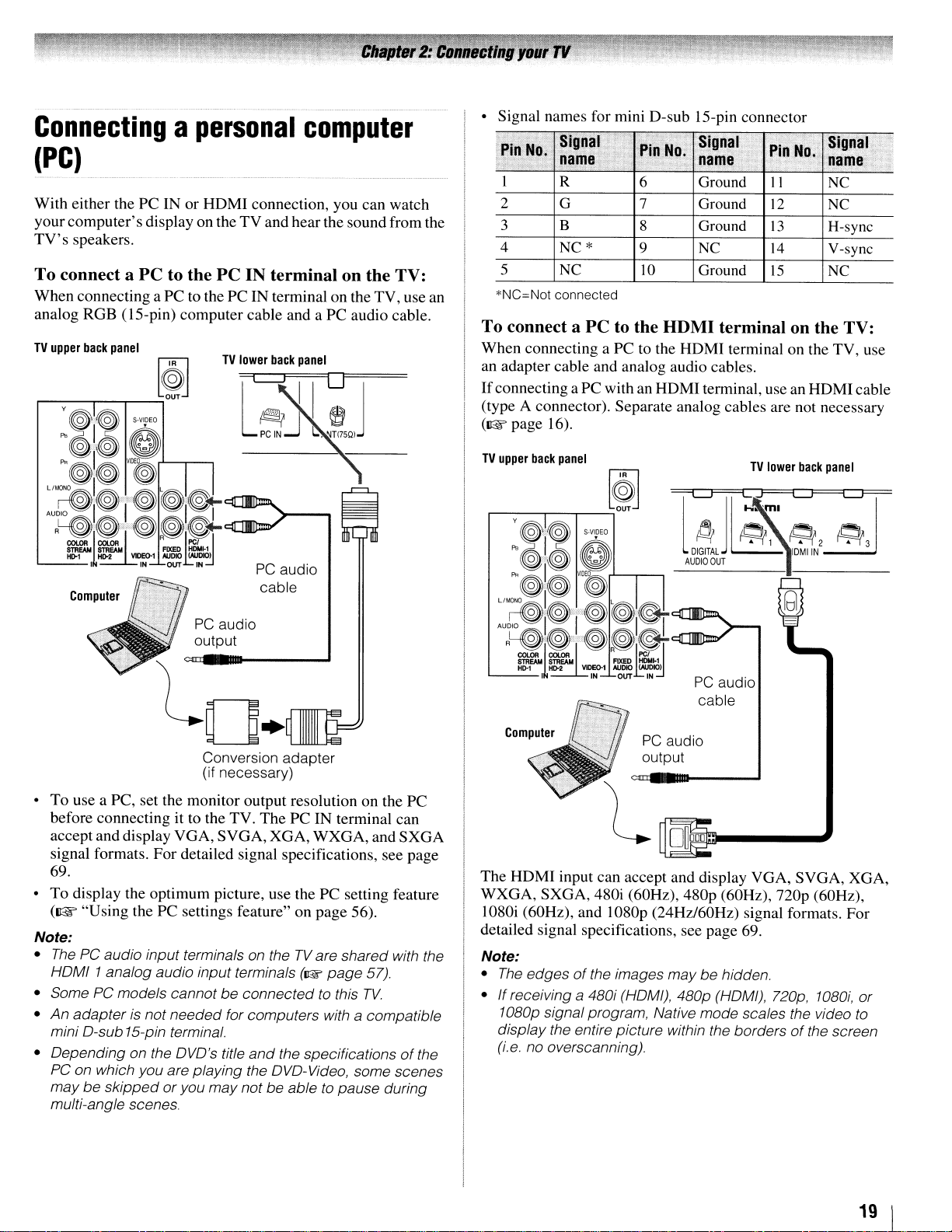
Connectingapersonal
computer
(PC)
With
either thePCIN or HDMI connection, you can watch
computer's
your
TV's
speakers.
To connect a PC to the PC IN terminal on the TV:
When connecting a PC to the PC IN terminal on the TV, use an
analog RGB (IS-pin) computer cable and a
TV
upper
back
display on theTVand hear the sound from the
PC
audio cable.
panel
• Signal names for mini D-sub IS-pin connector
Pin
,
1 R
2
3
4
5
*NC=Not connected
Signal
No.
name
G 7
B
NC*
NC
Pin
,.,
6
8
9
10
No.
Signal
name
Ground
Ground
Ground
NC
Ground
Pin
T
II
12
13
14
15
No.
i
Signal
name
NC
NC
H-sync
V-sync
NC
1-"
'v
To connect a PC to the HDMI terminal on the TV:
When
connecting aPCto the HDMI terminal on the TV, use
an adapter cable and analog audio cables.
If
connecting aPCwith an HDMI terminal, use an HDMI cable
(type A connector). Separate analog cables are not necessary
(1&
page 16).
TV
upper
back
panel
!
,
PC
audio
audio
SVGA,
cable
ThePCIN
XGA,
WXGA,
terminal can
Computer
PC
output
Conversion adapter
(if necessary)
•
To
use a PC, set the monitor output resolution on the PC
before connecting it to the TV.
accept and display
signal formats.
VGA,
For
detailed signal specifications, see page
69.
To
display the optimum picture, use the PC setting feature
•
(~
"Using
Note:
•
The
PC audio input terminals on theTVare shared with the
HoMI
• Some PC models cannot
•
An
adapter
mini
o-sub
• Depending on the
PC
on which you are playing the oVo-Video, some scenes
maybeskippedoryou
multi-angle scenes.
the PC settings feature" on
1 analog audio input terminals
be
connected to this
is not
needed
15-pin terminal.
oVo's
for computers with a compatible
title
and
the specificationsofthe
may
not be able to pause during
(I@'
page
page
56).
TV.
and
57).
SXGA
PC
audio
cable
PC
audio
output
The
HDMI input can accept and display VGA,
WXGA,
SXGA, 480i (60Hz), 480p (60Hz),
nop
SVGA,
(60Hz),
XGA,
1080i (60Hz), and 1080p (24Hz/60Hz) signal formats. For
detailed signal specifications, see page 69.
Note:
•
The
edgesofthe images
If
receiving a 480i (HOM!), 480p (HOM!), 720p,
•
1080p signalprogram. Native mode scales the video to
display the entire picture within the bordersofthe screen
(i.e no overscanning).
maybehidden.
1080i,
or
19 1
Preparing
for
use
the
remote
control
Installing batteries
the
remote
control
Your TV remote control can operate your TV and many other
devices such as cable converter boxes, satellite receivers,
VCRs, DVD players, and HTIBs (home theater in a box), even
if
they are different brands.
If
you have a Toshiba device:
Your TV remote controlispreprogrammed to operate most
Toshiba devices
If
you havea non-Toshiba deviceora Toshiba device
that
the remote control is not preprogrammed to
(~page
24).
operate:
You can program the TV remote control so it will operate the
other device
(~
pages 22-32).
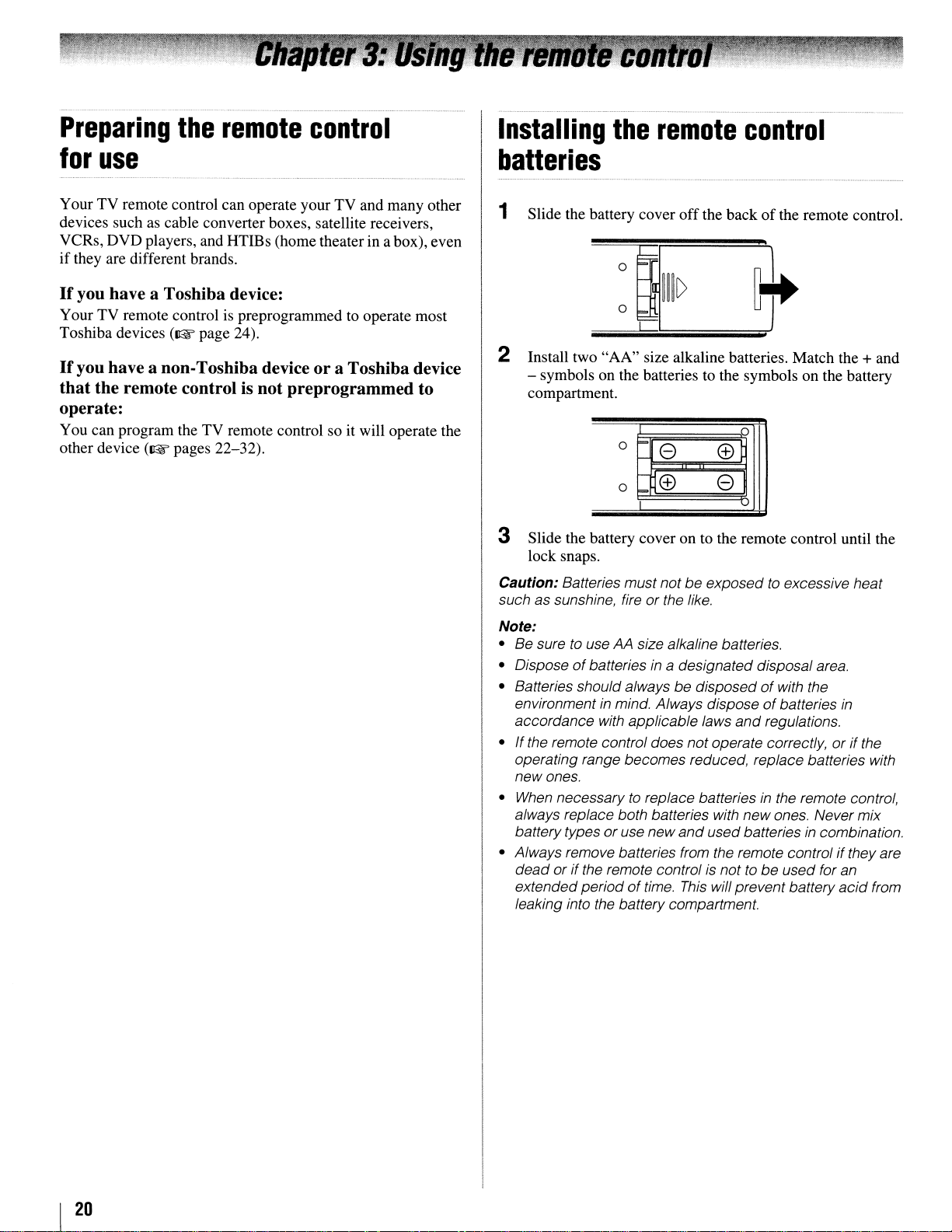
1
Slide the battery cover
2
Install two "AA" size alkaline batteries. Match the + and
- symbols on the batteries to the symbols on the battery
compartment.
0
o
e
ffi e
~
off
the backofthe remote control.
0
ffil
3 Slide the battery cover on to the remote control until the
lock snaps.
Caution:
such as sunshine, fire
Note:
• Be sure
• Dispose
• Batteries should always be disposed
environmentinmind. Always disposeofbatteries
accordance with applicable laws
• If the remote control does notoperate correctly, or if the
operating range becomes reduced, replace batteries with
new ones.
When
•
always replace both batteries with newones. Never mix
batterytypes
• Always remove batteries from the remote control ifthey are
dead
extendedperiodoftime.
leaking into the battery compartment.
Batteries must notbeexposedtoexcessive heat
or the like.
to
use AA size alkaline batteries.
of
batteriesina designateddisposal area.
of
with the
in
and
regulations.
necessarytoreplace batteriesinthe remote control,
oruse new
or if the remote control
and
used batteriesincombination.
is
nottobe
This
will prevent battery
used for an
acid
from
I
20
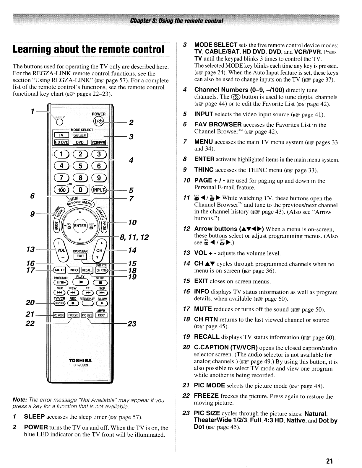
Learning
The buttons usedfor operatingtheTVonly are described here.
For
the
REGZA-LINK
section "Using
of
the remote control's functions, see the remote control
list
functional key chart
1
about
REGZA-LINK"
(~pages
~-
-S-.LE-EP----PQ-OW-E-R
IIII
D@".II
II
C!LJ
I"
ow!!
CD CD CD
the
remote
remote control functions, see the
(~page
22-23).
control
57).
For
a complete
rrt
..
II-
2
MODE
SELECT
~
....
11
IIII
3
I
4
ICABlEISAri
rnD
1"
CDCDffi
3
MODE
TV,
TV
The selected MODE key blinks each time any key
(1& page 24). When the Auto Input feature
can also be used
4
Channel
channels.
(1& page 44)
5 INPUT selects the video input source (1& page 41).
FAV BROWSER accesses the Favorites List in the
6
Channel Browser'"
7 MENU accesses the main TV menu system (1& pages
and 34).
8
ENTER
9
THINC accesses the
SELECT sets the five remote control device modes:
CABLE/SAT,
until the keypad blinks 3 timestocontrol the TV.
Numbers
The
activates highlighted items in the main menu system.
HD
DVD, DVD,
to
change inputs on the TV
(0-9,
-/100)
@Q)
button is used to tune digital channels
or
to edit the Favorite List (1& page 42).
(1& page 42).
THINC
and VCR/PVA. Press
is
set, these keys
(1lW
directly tune
menu (1& page 33).
is
page 37).
pressed.
33
CD
6
13
16
17
20~~
21
22
(10ofmIQNPUTj
--7.i+----~
ill
TOSHIBA
CT-90303
CD
III
10
8,
11,
14
15
18
19
'---------nr=---23
12
10
PAGE +
Personal E-mail feature.
11 ;
....
Channel Browser'" and tune to the previous/next channel
in the channel history
buttons.")
12
Arrow
these buttons select or adjust programming menus. (Also
see;
13
VOL + - adjusts the volume level.
14
CH
menu is on-screen
15 EXIT closes on-screen menus.
16 INFO displays TV status information as well as program
details, when available
17
MUTE reduces or turns
18
CH
(~page
19 RECALL displays TV status information
20
C.CAPTION
selector screen. (The audio selector is not available for
analog channels.)
also possible to select TV mode and view one program
while another is being recorded.
/-
are used for paging up and down in the
/;1
~
While watching TV, these buttons open the
(~
page 43). (Also see "Arrow
buttons
....
/;1
£ ... cycles through programmed channels when no
RTN returns to the last viewed channel or source
45).
(£
~.)
(1& page 36).
(TVNCR)
(~
.......~)When a menu is on-screen,
(~
page 60).
off
the sound
opens the closed caption/audio
page 49.) By using this button, it
(~
page 50).
(~page
60).
is
Note:
The
error message "Not Available"
a key for a function that
press
1 SLEEP accesses the sleep timer (1& page 57).
2
POWER turns the
blue LED indicator on the
is
not available.
TV
on andoff. When theTVis on, the
TV
may
appear
front will be illuminated.
ifyou
21 PIC MODE selects the picture mode
22
FREEZE freezes the picture. Press again to restore the
moving picture.
23
PIC SIZE cycles through the picture sizes: Natural,
TheaterWide
Dot (1& page 45).
1/213, Full,
4:3
(~
page 48).
HD,
Native, and Dot
21
by
I
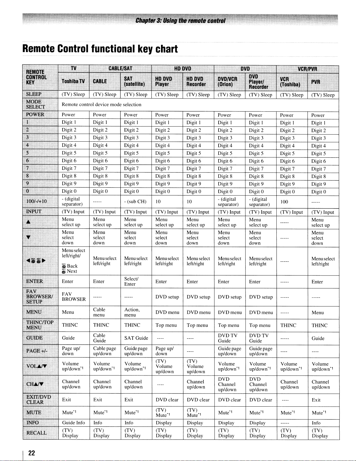
Remote
Control
functional
key
chart
REMOTE
CONTROL
·K.EY
SLEEP
:
MODE
SELECT
POWER
1::
)(
).
:,6"
•
,7
'"8
9
0
10?/./+1O
INPUT
.&
·4
J
T
.,
..
;;~
,.:
;;e-;':;·"v",
",
:r~!r,:::r\f\.·
_;SETUP:
MENU
THiNcrrop
MENU
GUIDE
I~
PAGE+/~
VOL~
CH,&rf,
EXITIDVD
"
;'CLEAR
0~
,,:.,',J;~
fm
!';C'••.",·
,.t
,
"
.
"
....
{
"
.e,'
;.,
";e,
,:t
(,
:
OWSERI
,
...
:
'W
IT'r;{:~
....
:(,L"
."
,TV,H"
"
'.
Toshiba
-:;-
)
"
;;
"
••
".
'.
" "
TV
',·:i., '
(TV) Sleep (TV) Sleep (TV) Sleep
Remote control device mode selection
Power Power
Digit I Digit I Digit I Digit I Digit I
Digit 2 Digit 2 Digit 2 Digit 2 Digit 2 Digit 2 Digit 2
Digit 3 Digit 3 Digit 3 Digit 3 Digit 3 Digit 3 Digit 3 Digit 3
Digit 4 Digit 4 Digit 4 Digit 4 Digit 4 Digit 4
Digit5
Digit 6 Digit 6 Digit 6 Digit 6 Digit 6 Digit 6
Digit 7
Digit 8 Digit 8 Digit 8
Digit 9 Digit 9 Digit 9 Digit 9 Digit 9 Digit 9 Digit 9 Digit 9
Digit 0 Digit 0 Digit 0 Digit 0 Digit 0 Digit 0 Digit 0
- (digital
separator) separator) separator)
(TV) Input (TV) Input
Menu Menu Menu Menu Menu Menu Menu Menu
select up select up select up select up select up select up select up
Menu Menu Menu Menu Menu Menu Menu Menu
select select select select select select select ----- select
down down down down down down down down
Menu select
left/right/
;S
Back
d5iNext
Enter Enter
FAV
BROWSER
Menu
THINC THINC
Guide
Page up/ Cable page Guidepage
down
Volume Volume
up/down" up/down" up/down"
Channel
up/down up/down up/down
Exit Exit Exit
Mute" Mute"
Guide Info Info
(TV) (TV)
Display
CABLE/SAT
CABLE
Digit 5 Digit 5 Digit 5 Digit 5
Digit 7 Digit 7 Digit 7 Digit 7 Digit 7 Digit 7 Digit 7
----- - (sub
Menuselect Menu select Menuselect Menu select
left/right left/right left/right left/right left/right
----- -----
Cable
menu menu
Cable
Guide
up/down up/down
Channel Channel Channel
Display Display Display
Itoovo
setup
clear
.".
OVDNCR
(Orion)
Digit I
Digit 5 Digit 5 Digit 5 Digit 5
- (digital - (digital
Menuselect Menu select Menu select
DVD
Top
DVDTV DVDTV
Guide Guide
Guide page Guide page
Volume
up/down"
DVD DVD
Channel Channel
up/down up/down
DVD
Mute" Mute" Mute" Mute"
,SAT
(salelllle)
Power
CH)
(TV) Input (TV) Input (TV) Input (TV) Input (TV) Input (TV) Input (TV) Input
Select/
Enter
Action,
THINC
SAT
Guide
Volume
Mute"
Info Display Display Display
(TV) (TV) (TV) (TV)
HO
OVO
Player
(TV) Sleep (TV) Sleep (TV) Sleep (TV) Sleep
Power
Digit 8 Digit 8 Digit 8 Digit 8 Digit 8 Digit 8
10
Enter Enter Enter Enter Enter
DVD
setup
DVDmenu DVDmenu DVDmenu DVDmenu
Top
menu
----
Page
up/
down up/down up/down
(TV)
Volume Volume
up/down up/down
----
DVD clear
(TV) (TV)
Mute" Mute"
HO
OVO
Recorder
Power Power Power
10
DVD
Top
menu
----
----
(TV)
up/down
DVD
Display Display Display Display Display
"
setup
menu
clear
OVO
ovo
Player/
Recorder
Digit I
Digit4
Digit 6 Digit 6 Digit 6
left/right
DVD
setup
Top
menu
Volume Volume Volume
up/down" up/down"
DVD
clear
Display
(TV) (TV) (TV)
eVCR/PVR
;~
,'-'
VCR;
,
(1'?s,h~ba)
(TV) Sleep (TV) Sleep
Power
Digit I
Digit 2 Digit 2
Digit4
Digit 0 Digit 0
100
-----
-----
-----
,
-----
-----
THINC THINC
-----
---- ----
Channel Channel
up/down up/down
----
----- Info
PVR
Power
Digit I
Digit 3
Digit 4
Digit 7
Digit 9
-----
select up
left/right
-----
Menu
Guide
up/down"
Exit
,
I
22
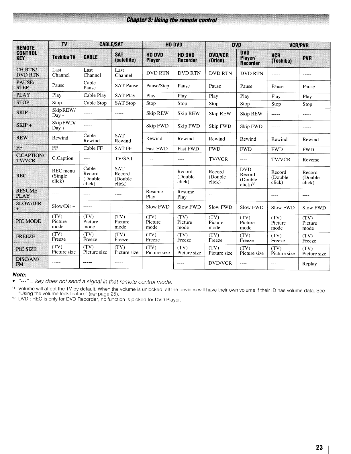
SAT
Pause
Pause/Step
Pause Pause Pause Pause Pause
Cable Play
Stop Cable Stop SAT Stop Stop Stop Stop Stop Stop
SkipREW/
Day SkipFWD/
Day
+
Cable SAT
Rewind
Cable
FF
Cable SAT
Record Record
(Double
click) click)
(TV) (TV) (TV) (TV)
Picture
mode mode
(TV) (TV)
Freeze Freeze
(TV) (TV) (TV) (TV)
Picture size
SAT
Play Play Play Play Play Play PlayPlay
SkipREW
Skip FWD Skip FWD Skip FWD Skip FWD
Rewind
SATFF
TV/SAT
(Double
Picture Picture Picture Picture Picture Picture
Picture size
Rewind Rewind Rewind Rewind Rewind
Fast FWD Fast FWD FWD FWD FWD
Resume
Play Play
Slow FWD Slow FWD
mode mode mode mode mode
(TV) (TV) (TV)
Freeze Freeze Freeze Freeze Freeze
Picture size Picture size Picture size Picture size Picture size
SkipREW
Record Record
(Double (Double
click)
Resume
Skip REW
TVNCR
click)
Slow FWD Slow FWD Slow FWD Slow FWD
(TV) (TV) (TV) (TV)
(TV) (TV) (TV)
SkipREW
TVNCR
DVD
Record
(Double
click)"2
(TV) (TV) (TV)
Record
(Double (Double
click)
Stop
Rewind
FWD
Reverse
Record
click)
Picture
mode
Freeze
(TV)
Picture size
Note:
"---" = key does
•
"1
Volume
"Using the volume lock feature"
"2
OVO: RECisonly for
will
not
send
affect theTVby default. When the volumeisunlocked,
OVO
a signal
Recorder, no functionispicked
(I@f
in
that remote control
page
25).
for
mode
OVO
.
all
the
Player.
devices
will
DVDNCR
have
their own volumeiftheir10has
volume
Replay
data.
See
23 I
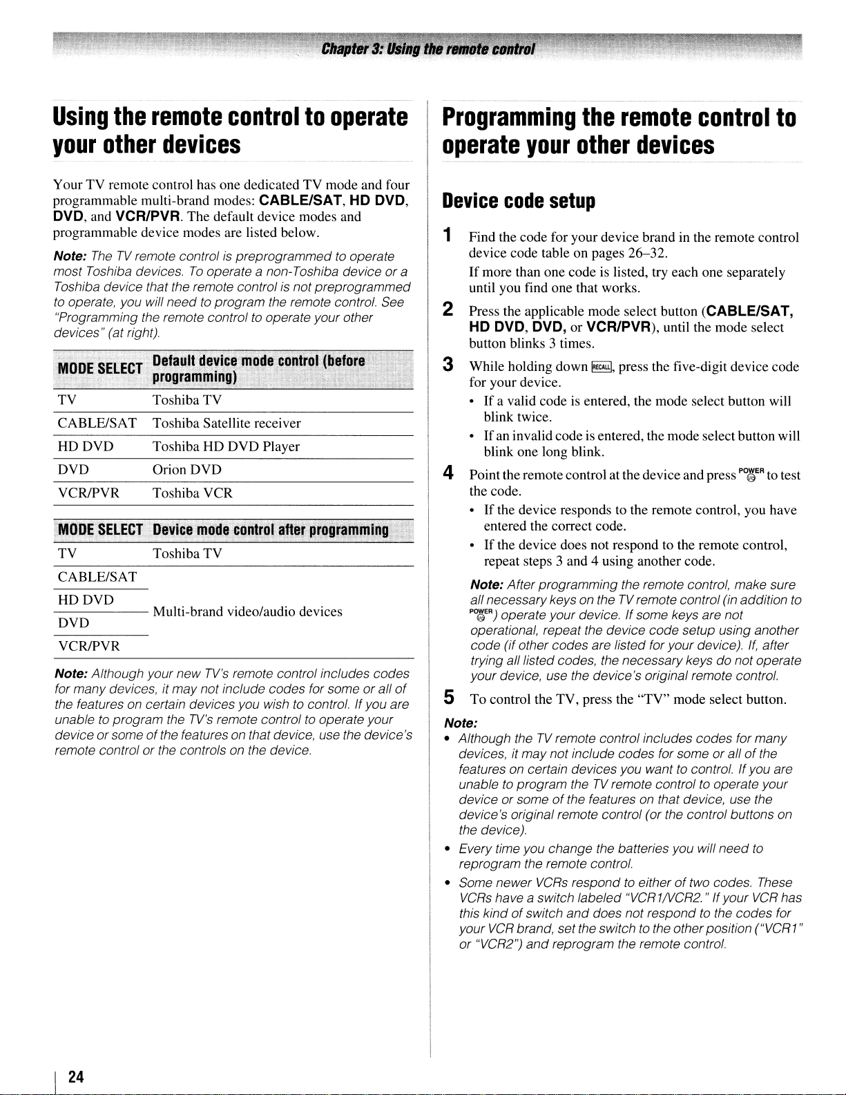
Using
the
remote
controltooperate
Programming
the
remote
control
to
your
Your TV remote control has one dedicated TV mode and four
programmable multi-brand modes: CABLE/SAT, HD DVD,
DVD, and VCR/PVA. The default device modes and
programmable device modes are listed below.
Note:
most Toshiba devices.Tooperate a non-Toshiba device or a
Toshiba device that the remote controlisnotpreprogrammed
to
"Programming the remote controltooperate your other
devices" (at right).
TV
CABLE/SAT
HDDVD
DVD
VCR/PVR
TV
CABLE/SAT
HDDVD
DVD
VCR/PVR
Note: Although your new
for many devices, it maynot include codes for someorall
the features on certain devices you wishtocontrol. If you are
unabletoprogram the
device or some
remote control or the controls on the device.
other
TheTVremote controlispreprogrammedtooperate
operate, you will needto program the remote control. See
devices
Toshiba TV
Toshiba Satellite receiver
Toshiba HD DVD Player
Orion DVD
Toshiba VCR
Toshiba TV
TV's
remote control includes codes
TV's
remote controltooperate your
of
the features on that device, use the device's
of
operate
Device
1
Find the code for your device brand in the remote control
device code table on pages 26-32.
If
more than one code is listed, try each one separately
until you find one that works.
Press the applicable mode select button (CABLE/SAT,
2
HD DVD, DVD, or VCR/PVR), until the mode select
button blinks 3 times.
3 While holding down
for your device.
•Ifa valid code is entered, the mode select button will
blink twice.
•
If
blink one long blink.
your
code
an invalid codeisentered, the mode select button will
other
setup
~,
devices
press the five-digit device code
4 Point the remote control at the deviceand press P0{/gER to test
the code.
•
If
the device responds to the remote control, you have
entered the correct code.
•Ifthe device does not respond to the remote control,
repeat steps 3 and 4 using another code.
Note: After programming the remote control, make sure
all necessarykeys on theTVremote control (in addition to
PO~ER)
operate your device.Ifsome keys are not
operational, repeat the device code setup using another
code (if other codes are listed for yourdevice).
trying alllisted codes, the necessarykeys do notoperate
your device, use the device's original remote control.
If,
after
S To control the TV, press the "TV" mode select button.
Note:
• Although theTVremote control includes codes for many
or
devices, it may not include codes for some
features on certain devices you want
to
unable
device or someofthe features on that device, use the
device's original remote control (or the control buttons on
the device).
• Every time you change the batteries you will need
reprogram the remote control.
• Some newer
VCRs
this kindofswitch
your
or "VCR2")
program theTVremote controltooperate your
VCRs
respondtoeitheroftwo codes. These
have a switch labeled "VCR1NCR2." Ifyour
and
does not respondtothe codes for
VCR
brand, set the switchtothe otherposition ("VCR1"
and
reprogram the remote control.
to
allofthe
control.Ifyou are
to
VCR
has
I
24
 Loading...