

TOSHIBA 52HMX84, 62HMX84 Service Manual

FILE NO. 020-200418
SERVICE MANUAL
Projection Television
52HMX84
62HMX84
DOCUMENT CREATED IN JAPAN, Aug., 2004

TABLE OF CONTENTS
CHAPTER 1 GENERAL ADJUSTMENTS
SAFETY INSTRUCTIONS .............................................................................................................................................. 3
SERVICE MODE ............................................................................................................................................................ 4
ELECTRICAL ADJUSTMENT ........................................................................................................................................ 7
CHAPTER 2
SPECIFIC INFORMATIONS
SETTING & ADJUSTING DATA ...................................................................................................................................... 8
LOCATION OF CONTROLS ........................................................................................................................................... 9
PROGRAMMING CHANNEL MEMORY ....................................................................................................................... 11
LAMP UNIT REPLACEMENT ....................................................................................................................................... 13
LIGHT ENGINE REPLACEMANT.................................................................................................................................
PARTS REPLACEMENT IN LIGHT ENGINE...............................................................................................................
EXPLODED VIEW ........................................................................................................................................ ................ 20
MECHANICAL DISASSEMBLY .................................................................................................................................... 21
CHASSIS REPLACEMENT PARTS LIST ..................................................................................................................... 22
PC BOARDS TOP AND BOTTOM VIEW ..................................................................................................................... 30
TERMINAL VIEW OF TRANSISTORS ......................................................................................................................... 42
CIRCUIT BLOCK DIAGRAM ........................................................................................................................................ 45
SPECIFICATIONS .................................................................................................................................................... END
APPENDIX:
CIRCUIT DIAGRAM
16
18
-
2
-

CHAPTER 1 GENERAL ADJUSTMENTS
SAFETY INSTRUCTIONS
SAFETY PRECAUTION
WARNING: Service should not be attempted by anyone unfamiliar with the necessary precautions on this receiver. The following
are the necessary precautions to be observed before servicing this chassis.
1. An isolation transformer should be connected in the power line between the receiver and the AC line before any service is
performed on the receiver.
2. When the replacing a chassis in the cabinet, always be certain that all the prospective devices are put back in place, such
as; non-metallic control knobs,insulating covers, shields, isolation resistor-capacitor network etc.
PRODUCT SAFETY NOTICE
Many electrical and mechanical parts in this chassis have special safety-related characteristics. These characteristics are
often passed unnoticed by a visual inspection and the protection afforded by them cannot necessarily be obtained by using
replacement components rated for higher voltage, wattage, etc. Replacement parts which have these special safety characteristics are identified in this manual and its supplements; electrical components having such features are identified by the
international hazard symbols on the schematic diagram and the parts list.
Before replacing any of these components, read the parts list in this manual carefully. The use of substitute replacement
parts which do not have the same safety character istics as specified in the parts list may create shock, fire, or other hazards.
-
3
-
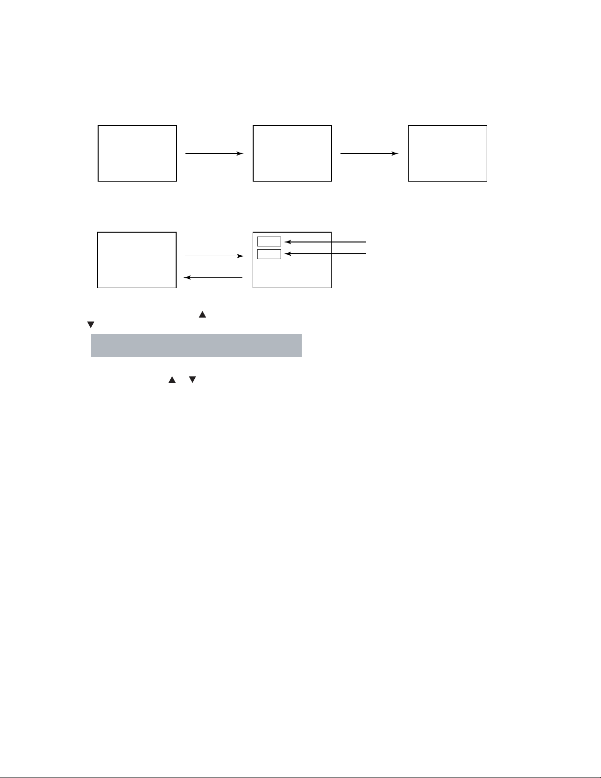
SERVICE MODE
1. ENTERING TO SERVICE MODE
1) Press MUTE button twice
on Remote Control.
MUTE
2) Press MUTE button
again to keep pressing.
2. DISPLAYING THE ADJUSTMENT MENU
1) Press MENU button on TV.
Service mode
S
Press
Press
Adjustment mode
3. SELECTING THE ADJUSTING ITEMS
1) Every pressing of CHANNEL button in the service mode changes the adjustment items in the order of table-2.
( button for reverse order)
Refer to table-1 for preset data of adjustment mode.
(See SETTING & ADJUSTING DATA on page 8)
3) While pressing the MUTE button,
press MENU button on TV set.
S
(Service mode display)
Item
Data
4. ADJUSTING THE DATA
1) Pressing of VOLUME or button will change the value of data in the range from 00H to FFH. The variable range
depends on the adjusting item.
5. EXIT FROM SERVICE MODE
1) Pressing POWER button to turn off the TV once.
-
4
-
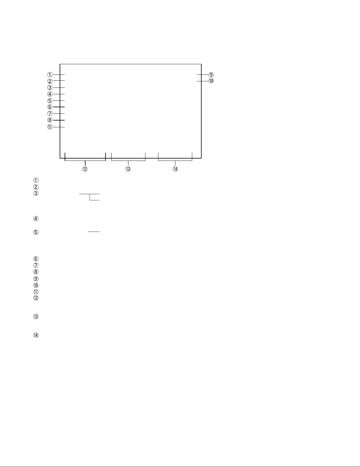
6. SELF DIAGNOSTIC FUNCTION
1) Press “9” button on Remote Control during display of adjustment menu in the service mode.
The diagnosis will begin to check if interface among IC’s are executed properly.
2) During diagnosis, the following displays are shown.
SELF CHECK
NO. 23 * * * * * *
POWER : 000
BUS LINE : OK
BUS CONT : OK
BLOCK : MAIN SUB
SET ID : 80
E2P VER : 08
OPT1 : 00 OPT2 : A0
SW VER : DLE May 13 2004 17:**:**
HDMI
NO ********
ERR CDDE : 00
BEP
SW VER : 42
E2R VER : 02
Thermo1 : +51
Thermo2 : +50
TIME
TV : ******
LAMP :
****
Part number of microprocessor (IC609)
Operation number of protection circuit (The number of times of the power supply OFF by fan stop) . . . . “000” is normal.
BUS line check “OK” ................... Normal
“SCL-GND” or “NG” ........... SCL-GND short circuit
“SDA-GND” or “NG” ........... SDA-GND short circuit
“SCL-SDA” or “NG” ............ SCL-SDA short circuit
BUS line ACK (acknowledge) check
“OK” ................... Normal
Sync. signal check Green display ..... Normal
Red display ........ NG
MAIN ........ Main sync
SUB .......... Sub sync (when turn on the PIP)
ID code for TV Set
Version of "EEP"
Data for "OPT"
Temperature of DMD
Temperature of the color wheel neighborhood
Software version history
HDMI Software
NO ***** .....Serial No.
ERR CODE .....Error Code
BEP Software Version
SW VER : **.....Version
E2P VER : ** EEP ROM Version
Use time
TV .....TV set on time (hour)
LAMP.....LAMP set on time (hour)
(It may shift from TV set on time.)
-
5
-
7. LED indicationsn
The green and red LED lights on the TV control touchpad
(on the lower right corner of the TV screen)
indicate the TV's current status, as follows:
.
Green ON = Control touchpad being pressed.
.
Red ON = Power ON.
.
Green and/or Red blinking
(see table below for condition and solution).
Control touchpad on TV front
MENUVOLUMECHANNELEXITTV/VIDEO POWER
Red indicator
Green indicator
LED Indication
1
Red and Green turn off.
2
Red and Green turn off.
Red lights solid and Green off.
3
4
Red and Green lights solid.
5
Green blinks at 1-second intervals;
Red off.
Green blinks at 0.3-second inter-
6
vals; Red lights solid.
Green lights solid and Red blinks
7
at 0.5-second intervals.
Green and Red blink at 1-second
8
intervals.
9
Red blinks at 0.5-second intervals;
Green off.
10
Red blinks at 1-second intervals;
Green off.
11
Red blinks three times; Green off.
12
Red and Green blinks three times.
Condition
Power supply OFF. (AC)
Power supply OFF. (Standby)
(North America)
Power supply ON.
Touched the touchpad
Lamp LPS mode
The lamp is not working properly.
The lamp unit door is not seated
properly. (U)
The lamp is not working properly
after the third automatic reset (see
item #7). (U)
FAN (Light engine unit) has
stopped.
BUS line is damaged
The color wheel has stopped.
Temperature rises abnormally.
(U) is restoration by the user.
Solution
The TV automatically will try to reset itself
three times.
Turn the POWER OFF and unplug the power
cord. Review “How to replace the lamp unit”
on pages 13-15 to ensure that the lamp unit
door is installed securely.
Turn the POWER OFF and then ON again. If
the problem persists, replace“the lamp unit
(see pages 13-15).
• Is the output voltage of the supply voltage
regulator for the FAN in the power circuit
normal?
• Has dust accumulated in the FAN?
If the output voltage is not abnormal,
replace the faulty FAN with a new one.
• Check the faulty device through the self
diagnostics function under SERVICE mode.
• Does BUS line (SOL, SDA) work normally?
If the BUS line is under abnormal
conditions, replace the faulty device with
a new one.
• Is the output voltage of the power supply
circuit normal?
If the output voltage is normal, replace the
engine with a new one.
• Is the ventilating hole in the set (exhaust
slot on the rear) blocked or covered?
• Is FAN rotating normally?
• Has dust accumulated in the ventilating
hole?
If no abnormally conditions are found,
replace the engine with a new one.
-
6
-

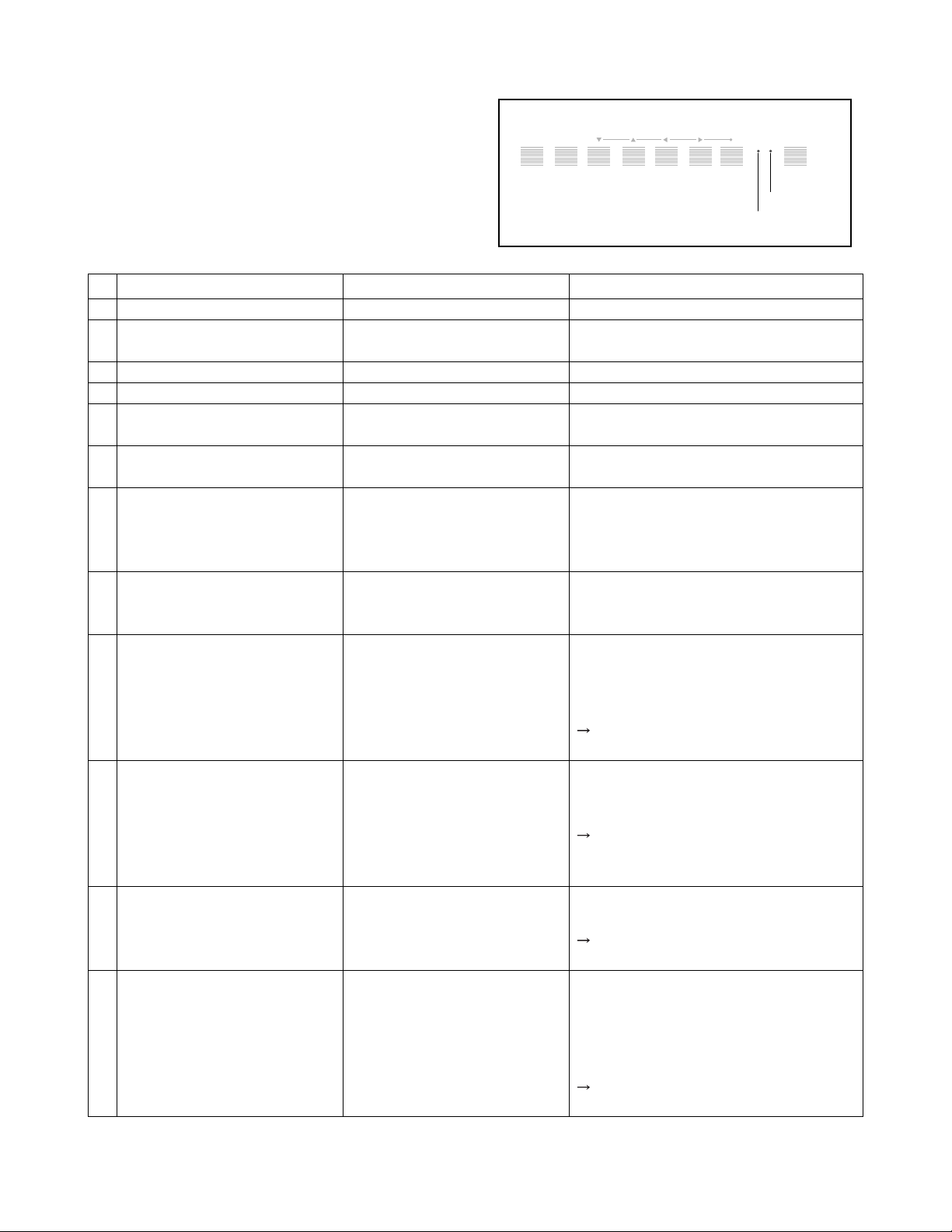
ELECTRICAL ADJUSTMENT
DLE-PJTV (52HM84) Adjustment Method
NO
1
2
3
Adjustment ITEM
ADC
Offset Voltage
(Scaler board)
Horizontal
Picture Position (HPOS)
Vertical
Picture Position (VPOS)
Process /Instructions
1. Make TV to be in 'M'.
2. Connect 10 Step video signal (1080i) to 'Color
Stream1'.
3. Change Video Input to Color Stream1.
4. Start Auto adjustment by '40 EE A3 C5' remote
code sending.
1. Adjust HPOS data to make Left and Right side
picture position to be equality.
Alignment SPEC;
Difference of absolute value between left and
right side bar should be in 0.5 bar.
Absolute {(Left Side bar) - (Right Side Bar)} <
0.5
1. Adjust VPOS data to make Top and Bottom side
picture position to be equality.
Alignment SPEC;
Difference of absolute value between top and
bottom side bar should be in 0.5 bar.
Remark
[OSD INDICATION]
During Adjustment ; 'A/D ADJUSTING'
After Finish adjusting ;
'A/D ADJUSTMENT OK' -->
Adjustment succeeds.
'A/D ADJUSTMENT NG' -->
Adjustment fails.
[Set Condition]
Receive Ch12 (RETMA signal).
Picture size is FULL.
[Set Condition]
Receive Ch12 (RETMA signal).
Picture size is FULL.
White Balance
4
Absolute {(Top Side bar) - (Bottom Side Bar)}
< 0.5
1. Input white raster signal.
2. Measure the Color coordinate data by CA-210.
3. Adjust RDRV, GDRV and BDRV to make color
coordinate data to be x=0.271
y=0.276
+
0.002.
-
+
0.002 and
-
-
7
-
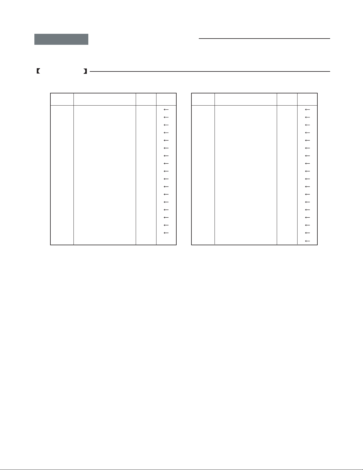
CHAPTER 2 SPECIFIC INFORMATIONS
SETTING & ADJUSTING DATA
SERVICE MODE
ADJUSTING ITEMS AND DATA IN THE SERVICE MODE:
Item Name of adjustment
RCUT R CUT OFF
GCUT G CUTOFF
BCUT B CUT OFF
RDRV R DRIVE
GDRV G DRIVE
BDRV B DRIVE
BRTC BRIGHT CENTER
SCNT
COLC COLOR CENTER
UVTT BASE BAND TINT
CNTX SUB CONTRAST MAX
HPOS H-POSITION (PAL/DFS)
VPOS
CWDH
CWDL
DMDB DMD BIAS
OPT0 TV SET OPTION
Note:
The image system data of RCUT-CNTX is different by each image format.
The NTSC value is indicated in the table.
SUB CONTRAST FOR TV
V-POSITION DC SHIFT (PAL/DFS)
COLOR WHEEL DELAY (HIGH)
COLOR WHEEL DELAY (LOW)
Preset Data
60H
60H
64H
48H
53H
5FH
76H
20H
D0H
40H
7FH
00H
00H
00H
FAH
03H
00H
Table-1
Item Name of adjustment
OPT2 TV SET OPTION
TVOP TV OPTION
PLLW0 PLL WAIT TIME
PLLW1 PLL WAIT TIME
PLLW2 PLL WAIT TIME
PLLW3 PLL WAIT TIME
PLLW4 PLL WAIT TIME
PLLW5 PLL WAIT TIME
V01 VOLUME (DATA)
V25 VOLUME (DATA)
V50 VOLUME (DATA)
V75 VOLUME (DATA)
V100 VOLUME (DATA)
MODH MODUS DATA HIGH
MODL MODUS DATA LOW
PRES FMAM PRESCALE
SCTH
SCTL
VOLUME SCART OPTION HIGH
VOLUME SCART OPTION LOW
Preset Data
A0H
40H
14H
03H
0FH
05H
14H
04H
23H
4AH
63H
6FH
73H
20H
91H
24H
73H
01H
-
8
-
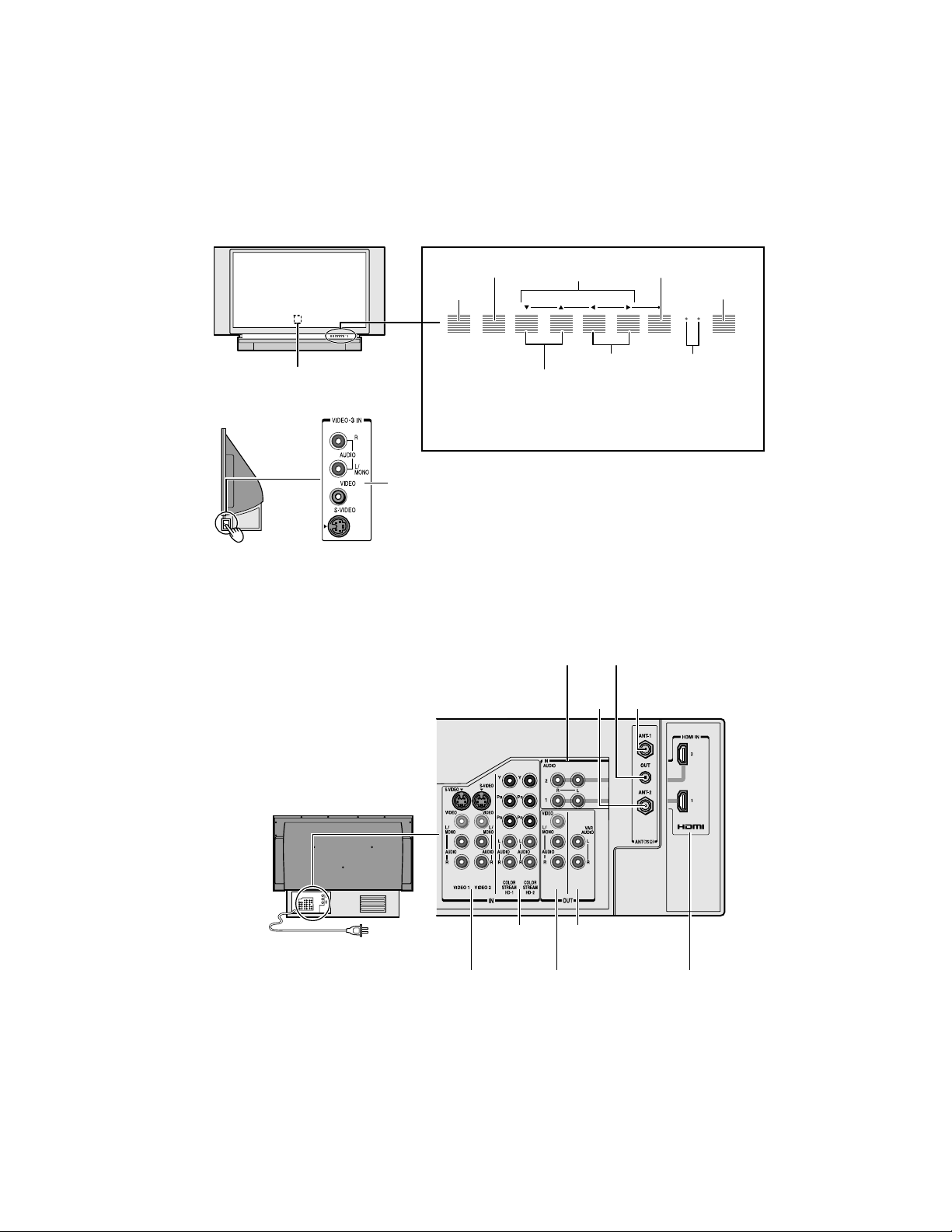
LOCATION OF CONTROLS
VIDEO 3
Front
Remote control sensor
(Behind the screen)
Side
Push to open.
Push to open.
Control touchpad on TV front (Gently touch the printed keys.)
EXIT
zyx •
TV/VIDEO
MENUVO LUMECHANNELEXITTV/VIDEO POWER
Volume x•
Channel zy
MENU
POWER
MENUVOLUMECHANNELEXITTV/VIDEO POWER
Green and Red
LED indicators*
* Green ON = Touchpad key being pressed;
Red ON = Power ON.
See page 64 for additional LED indications.
VIDEO 3
Vid
eo
/audio inputs
ANT OUTAUDIO
IN
ANT-2
ANT-1
IN
IN
Video/audio inputs
ANT OUTAUDIO
IN
ANT-2
ANT-1
IN
IN
Back
120 VAC
60 Hz
VIDEO 1/2
-
9
ColorStream
HD-1/HD-2
Video/Audio OUT
-
Variable
Audio OUT
HDMI IN
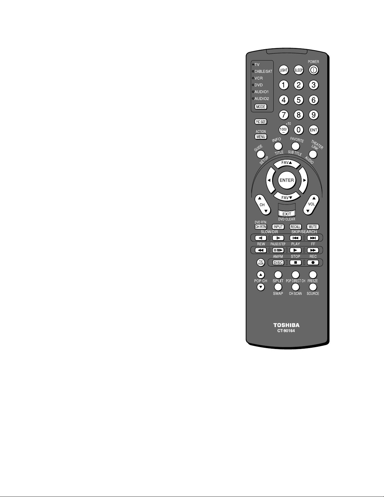
Remote Control
POWER
turns the TV on and off.
Press POWER to turn the TV on. The Red LED indicator will
be illuminated. Press POWER again to turn the TV off.
Note:
If the Quick Restart feature is in OFF mode, it can take up to several seconds for
the picture to appear. See page 28 for details.
SLEEP
allows access to the automatic TV shut-off function
LIGHT
The first press of the LIGHT button lights the keypad and turns
on the Illumination mode. With the Illumination mode on,
pressing any other key lights the keypad for 5 seconds (10 seconds
if you’re in programming mode).
Subsequent presses of the LIGHT button toggle between turning
the Illumination mode on and off.
Channel Numbers (0-9, 100)
MODE
cycles through the six device modes: TV, CABLE/SAT, VCR,
allow direct access to channels
DVD, AUDIO1, and AUDIO2. The mode indicator light will
remain lit for a few seconds.
PIC SIZE
cycles through the five pictures sizes: Natural, Theater Wide 1,
2, 3, and Full
FAVOR ITE
MENU
ENTER
yz x •
FAV yz
CH yz
VOL yz
EXIT
INPUT
MUTE
RECALL
allows access to the favorite channel search function
allows access to on-screen programming menus
sets programming menu information
select or adjust programming menus
cycles through favorite channels
cycles through programmed channels
adjusts the volume level
exits the programming menus
selects the video input source
mutes the sound
displays on-screen information
CH RTN
returns to the last viewed channels
POP CH yz
SPLIT
CH SCAN
FREEZE
SWAP
POP DIRECT CH
SOURCE
selects the POP (picture-out-picture) channel
turns the POP feature on and off
allows access to the programmed channel search functionx
freezes the picture. Press again to restore the picture.
switches the main and POP pictures
allows direct access to POP channels
selects the POP picture source
-
10
Note:
The error message “Not Available” will appear
if you press a key for a function that is not
available.
-
PROGRAMMING CHANNEL MEMORY
Adding channels to the TV’s memory
When you press Channel y or z, your TV will stop only on the
channels stored in the TV’s channel memory.
Follow the steps below and on the next page to program all active
channels into the TV’s memory.
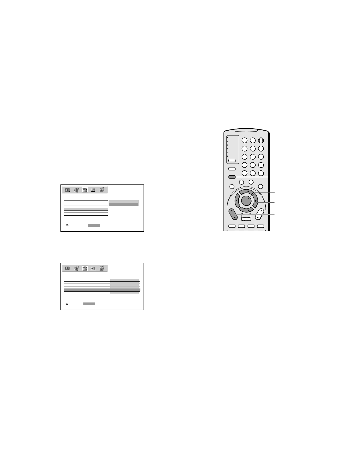
Programming channels automatically
Your TV can automatically detect all active channels in your area and
store them in its memory. After the channels are stored automatically,
you can manually add or erase individual channels.
To program channels automatically:
1. Press MENU, and then press x or • until the SET UP menu
appears.
2. Press y or z until TV/CABLE is highlighted, and then press
ENTER to display the pull-down menu.
3. Press y or z to highlight either TV or CABLE, depending on
which you use. If you use an antenna, highlight TV; if you use
cable channels, highlight CABLE.
LANGUAGE
CLOCK SET
ANT 1 / 2
TV / CABLE
CH PROGRAM
ADD / ERASE
SELECT::SETENTER
SET UP
CABLE
TV
Note:
To tune the TV to a channel not programmed
in the channel memory, you must use the
Channel Number buttons on the remote
control.
TV
CABLE/SAT
VCR
DVD
AUDIO1
AUDIO2
MODE
PIC SIZE
ACTION
MENU
E
D
I
U
G
P
U
T
E
S
CH
DVD RTN
CH RTN
SLOW/DIR
N
I
INPUT
F
T
POWER
LIGHT SLEEP
123
456
789
+10
100/
ENT
0
F
A
V
O
O
R
I
T
E
S
U
B
E
L
T
T
I
T
I
L
E
A
U
D
I
O
FAV
ENTER
FAV
VOL
EXIT
DVD CLEAR
RECALL
MUTE
SKIP/SEARCH
T
L
MENU
H
E
A
T
E
I
N
R
K
ENTER
yzx •
Channel yz
4. Press ENTER.
5. Press z to select CH PROGRAM.
LANGUAGE
CLOCK SET
ANT 1 / 2 ANT1
TV / CABLE CABLE
CH PROGRAM
ADD / ERASE
MOVE::STARTENTER
SET UP
ENGLISH
00:00
ADD
6. Press ENTER to start channel programming. The TV will
automatically cycle through all the TV or Cable channels
(depending on which you selected), and store all active channels
in the channel memory.
While the TV is cycling through the channels, the message
“Programming Now—Please Wait” appears.
7. When channel programming is complete, the message
“Completed” appears.
8. Press Channel y or z to view the programmed channels.
-
11
-
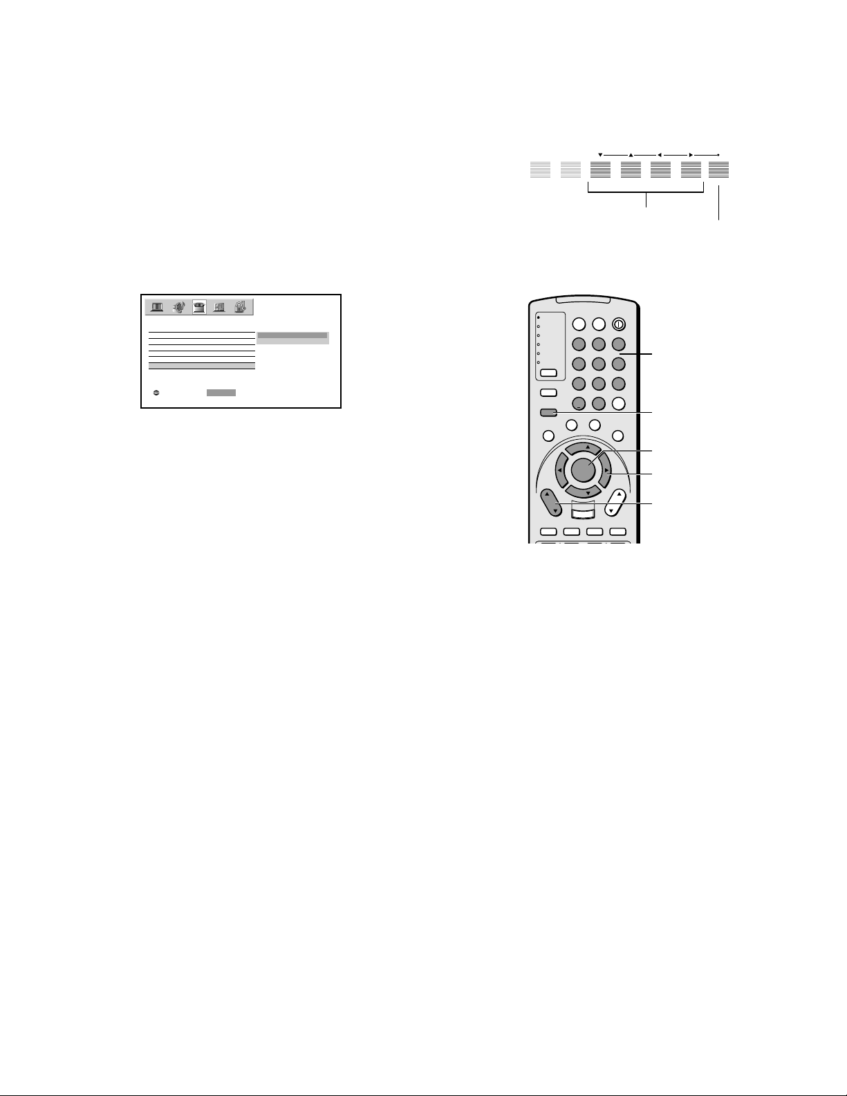
Adding and erasing channels manually
After you have programmed the channels automatically, you can
manually add or erase specific channels.
To add or erase channels:
1. Select the channel you want to add or erase. If you are adding a
channel, you must select the channel using the Channel Number
buttons.
2. Press MENU, and then press x or • until the SET UP menu
appears.
3. Press y or z to highlight ADD/ERASE, and then press ENTER
to display the pull-down menu.
Control touchpad on TV front
MENUVOLUMECHANNELEXITTV/VIDEO
x•zy
MENU
LANGUAGE
CLOCK SET
ANT 1 / 2
TV / CABLE
CH PROGRAM
ADD / ERASE
SELECT::SETENTER
SET UP
ADD
ERASE
4. Press y or z to select ADD or ERASE, depending on the
function you want to perform.
5. Repeat steps 1–4 for other channels you want to add or erase.
TV
CABLE/SAT
VCR
DVD
AUDIO1
AUDIO2
MODE
PIC SIZE
ACTION
MENU
E
D
I
U
G
P
U
T
E
S
CH
DVD RTN
CH RTN
SLOW/DIR
LIGHT SLEEP
123
456
789
+10
100/
0
F
A
V
O
O
R
F
I
T
N
I
S
U
B
E
L
T
T
I
T
I
L
T
E
FAV
ENTER
FAV
EXIT
DVD CLEAR
INPUT
RECALL
SKIP/SEARCH
E
POWER
A
U
D
VOL
MUTE
Channel
Number
ENT
I
O
MENU
T
H
E
A
T
L
E
I
N
R
K
ENTER
yzx •
Channel yz
-
12
-
 Loading...