

Toshiba 50PH36P Service Manual

FILE NO. 030-200315
SERVICE MANUAL
COLOUR TELEVISION
C03P Chassis
50PH36P
PUBLISHED IN JAPAN Dec., 2003 YC

TABLE OF CONTENTS
CHAPTER 1 GENERAL ADJUSTMENTS
SAFETY INSTRUCTIONS .............................................................................................................................................. 3
CRT ASSEMBLY REPLACEMENT AND MOUNTING .................................................................................................... 4
PICTURE TUBE COMPONENTS ADJUSTMENT.......................................................................................................... 6
SERVICE POSITION ......................................................................................................................................................9
SERVICE MODE ......................................................................................................................................................... 10
DESIGN MODE ........................................................................................................................................................... 13
ELECTRICAL ADJUSTMENT ..................................................................................................................................... 14
CONVERGENCE ADJUSTMENT ............................................................................................................................... 21
CIRCUIT CHECKS ...................................................................................................................................................... 28
CHAPTER 2 SPECIFIC INFORMATIONS
SETTING & ADJUSTING DATA ................................................................................................................................... 29
LOCATION OF CONTROLS ........................................................................................................................................ 30
MECHANICAL DISASSEMBLY ................................................................................................................................... 32
CHASSIS AND CABINET REPLACEMENT PARTS LIST ........................................................................................... 33
PC BOARDS LAYOUT TOP VIEW ............................................................................................................................... 50
PC BOARDS TOP VIEW .............................................................................................................................................. 51
TERMINAL VIEW OF TRANSISTORS ........................................................................................................................ 77
CIRCUIT BLOCK DIAGRAM ....................................................................................................................................... 80
SPECIFICATIONS .................................................................................................................................................... END
APPENDIX:
CIRCUIT DIAGRAM
– 2 –

CHAPTER 1 GENERAL ADJUSTMENTS
SAFETY INSTRUCTIONS
WARNING: BEFORE SERVICING THIS CHASSIS, READ THE “X-RAY RADIATION PRECAUTION”, “SAFETY PRECAU-
TION” AND “PRODUCT SAFETY NOTICE” INSTRUCTIONS BELOW.
X-RAY RADIATION PRECAUTION
1. Excessive high voltage can produce potentially hazardous
X-RAY RADIATION. To avoid such hazards, the high voltage must not be above the specified limit. The nominal value
of the high voltage of this receiver is (A) kV at zero beam
current (minimum brightness) under a (C) V AC power source.
The high voltage must not, under any circumstances, exceed (B) kV.
Refer to table-1 for high voltage (A), (B) & AC voltage (C).
(See SETTING & ADJUSTING DATA on page 31)
Each time a receiver requires servicing, the high voltage
should be checked following the HIGH VOLTAGE CHECK
procedure in this manual. It is recommended that the reading of the high voltage be recorded as a part of the service
record. It is important to use an accurate and reliable high
voltage meter.
SAFETY PRECAUTION
WARNING : Service should not be attempted by anyone unfamiliar with the necessary precautions on this receiver. The following
are the necessary precautions to be observed before servicing this chassis.
1. An isolation transformer should be connected in the power line between the receiver and the AC line before any service is
performed on the receiver.
2. Always discharge the picture tube anode to the CRT conductive coating before handling the picture tube. The picture tube
is highly evacuated and if broken, glass fragments will be violently expelled. Use shatter proof goggles and keep picture tube
away from the unprotected body while handling.
3. When replacing a chassis in the cabinet, always be certain that all the protective devices are put back in place, such as; nonmetallic control knobs, insulating covers, shields, isolation resistor-capacitor network etc.
2. The only source of X-RAY RADIATION in this TV receiver
is the picture tube. For continued X-RAY RADIATION protection, the replacement tube must be exactly the same
type tube as specified in the parts list.
3. Some part in this receiver have special safety-related characteristics for X-RAY RADIATION protection. For continued safety, parts replacement should be undertaken only
after referring to the PRODUCT SAFETY NOTICE below.
GENERAL ADJUSTMENTS
SPECIFIC INFORMATIONS
PRODUCT SAFETY NOTICE
Many electrical and mechanical parts in this chassis have special safety-related characteristics. These characteristics are
often passed unnoticed by a visual inspection and the protection afforded by them cannot necessarily be obtained by using
replacement components rated for higher voltage, wattage, etc. Replacement parts which have these special safety characteristics are identified in this manual and its supplements; electrical components having such features are identified by
the international hazard symbols on the schematic diagram and the parts list.
Before replacing any of these components, read the parts list in this manual carefully. The use of substitute replacement
parts which do not have the same safety characteristics as specified in the parts list may create shock, fire, X-ray
radiation or other hazards.
– 3 –
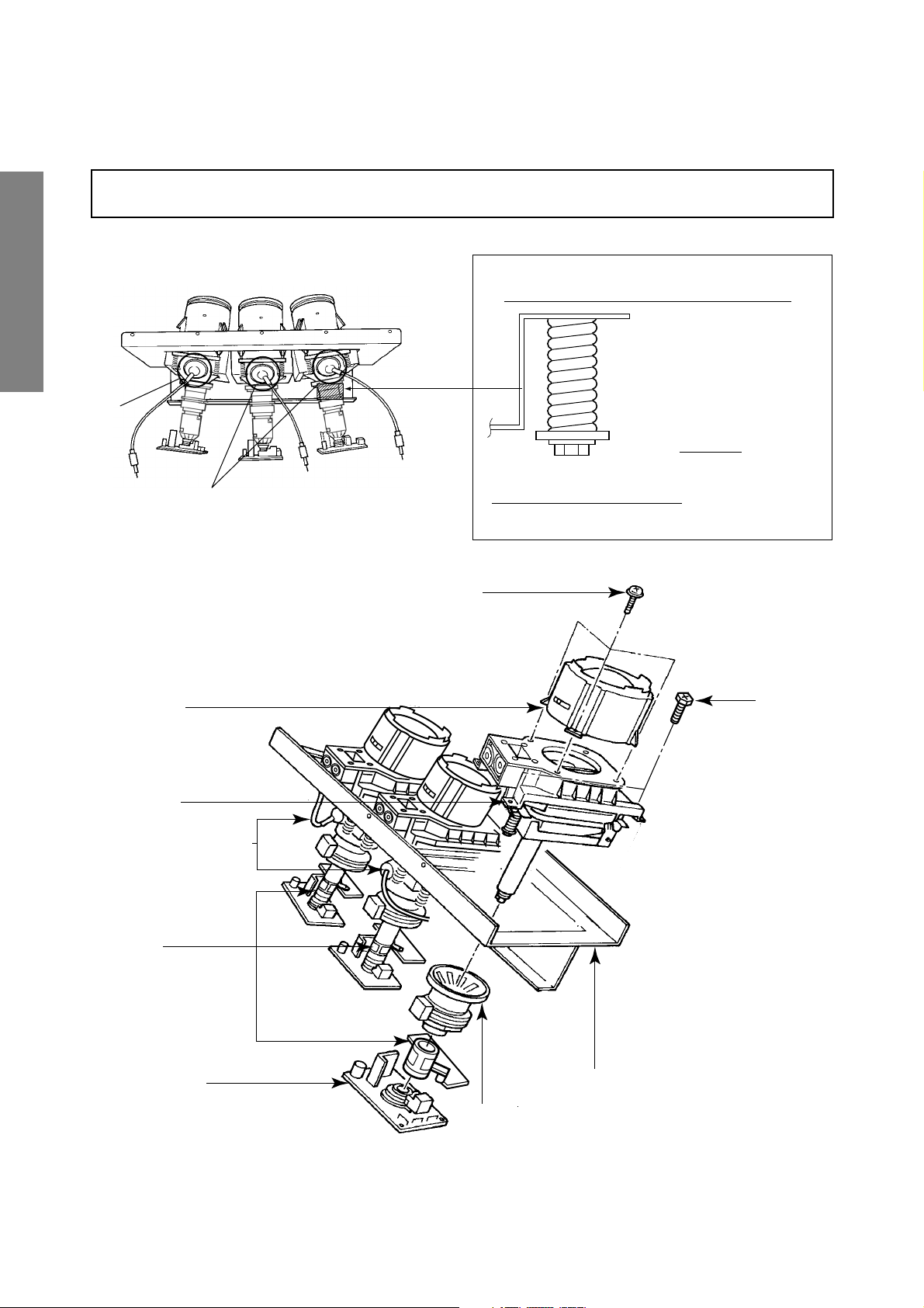
CRT ASSEMBLY REPLACEMENT AND MOUNTING
CAUTION : DO NOT LOOSEN THE HEX HEAD BOLTS WITH SPRINGS (12 PCS), BECAUSE THOSE ARE FOR
SEALING OF CRT COOLANT.
RGB
GENERAL ADJUSTMENTS
8 o'clock
4 o'clock
SPECIFIC INFORMATIONS
Lens Assembly
Attention Serviceman
The Hex Head
Bolts with
Springs. (see
sketch) used on
CRT assembly,
are “NOT”
Adjustment Screws
DO NOT LOOSEN-FLUID
LEAKAGE WILL OCCUR.
4 Screws
4 Screws
CRT Assembly
CRT Anode Cap Assembly
S.V.M. Coil
CRT DRIVE Board
CRT Mounting
Deflection Yoke and Conver Yoke
Lens and Neck Components View
– 4 –
TO REMOVE CRT (Same procedure for R, G, B)
1. Remove CRT DRIVE Board, S. V. M. COIL and
DEF. YOKE from CRT.
2. Remove Lens Assembly.
3. Detach CRT Anode Cap from CRT.
4. Remove CRT Assembly from CRT Mounting.
CRT REPLACEMENT (Same procedure for R, G, B)
Reverse the removal procedures except the followings.
1. Anode Cable should be replaced with new one.
See "SERVICING PRECAUTIONS" shown below.
2. Install silicon (T461B) to the CRT, replace the Anode
cable and put enough silicon again on around the Anode Cap as illustrated.
CAUTION: Align the Anode cable as illustrated on page
4.
ADJUSTING PROCEDURE IN REPLACING CRT
1. R.G.B. CUTOFF (SCREEN VR) ADJUSTMENT (page 6.)
2. R.G.B. FOCUS ADJUSTMENT (page 6.)
3. PICTURE TILT ADJUSTMENT (page 7.)
4. USER CONVERGENCE CENTER CHECK
(Refer to owner's manual.)
5. CENTERING ADJUSTMENT (page 7.)
6. CONVERGENCE ADJUSTMENT (page 21.)
7.
WHITE BALANCE ADJUSTMENT (page 14.)
Adjustments are complete.
Silicon
(On shaded area)
TSE3843W #23960136
Anode Cap
2 ~ 5 mm
GENERAL ADJUSTMENTS
SPECIFIC INFORMATIONS
SERVICING PRECAUTIONS
■ Do not use a magnetized screw driver for screws
of Deflection Yoke and Velocity Modulation Coil to
avoid magnetization of electron gun.
Magnetization of electron gun will degrade basic
function and result in unbalance of right and left
shift of user static convergence, and result in no
variable quantity.
Screw for
D.Y
15 ~ 25 mm
■ When replacing the anode cap assembly (CRT) or
anode lead assembly (F.B.T.), remove the anode
lead holder from old one and attach the holder
again to new anode lead.
■ Check the point of anode lead in a straight
line, if it is winding, please revise it.
Anode lead holder
Screw for SVM coi
– 5 –
WARNING: BEFORE SERVICING THIS CHASSIS, READ THE "X-RAY RADIATION PRECAUTION", "SAFETY PRE-
CAUTION" AND "PRODUCT SAFETY NOTICE" ON PAGE 3 OF THIS MANUAL.
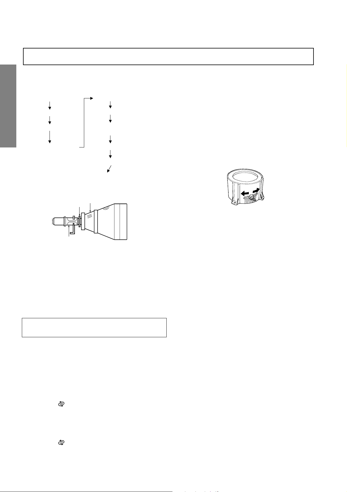
PICTURE TUBE COMPONENTS ADJUSTMENT
ADJUSTING PROCEDURE IN REPLACING CRT
Cutoff
Lens focus
Electrical focus
User convergence center check
Centering (PAL)
Convergence adjustment
(PAL/NTSC)
GENERAL ADJUSTMENTS
Yoke horizontal
DESCRIPTION OF NECK COMPONENTS
2
White balance
Sub bright adjustment
End
1
SPECIFIC INFORMATIONS
S.V.M. COIL
1 Deflection yoke and convergence yoke.
The position on the neck is required most front (CRT funnel side) and the screw is fastened after rotating yoke
adjusting picture tilt.
2 Centering magnet
After adjusting picture tilt, picture position is finally fixed
by this magnet.
In order to get maximum margin of user convergence control for center of screen, this magnet have to be used for
center convergence adjustment.
RGB FOCUS ADJUSTMENT
1. Call-up the adjustment mode (see page 10)
2. Press a button on the remote controller in order to display
the internally-generated cross-hatch (See TEST SIGNAL
SELECTION on page 11.)
3. Expose only RED by covering the GREEN and BLUE
lenses with caps.
4. Loosen the RED lens fixing screws (refer to Fig. a), and
adjust the RED lens focus to obtain the sharpest point
while observing the middle and peripheral sections of the
screen.
Fig. a
5. Use the focus VR of “R” of the focus pack in order to adjust
the electric focus in the middle and peripheral sections of
the screen to its sharpest level.
6. Check the RED focus of the whole screen and if necessary
repeat steps 4 and 5.
7. Fix the RED lens by tightening its fixing screws.
8. Expose only GREEN by covering the RED and BLUE
lenses with caps.
9. Display the internally-generated cross-hatch signal.
10. Adjust the GREEN lens focus on the left border of the
screen to its sharpest level, then check the focus on the
right border, and if it is at its sharpest level, fix it in that
position by tightening the lens screws.
PREPARATION
Operate the receiver for at least 5 minutes.
R, G, B CUTOFF (SCREEN VR) ADJUSTMENT
1. Adjust before replace the screen assembly.
2. Set user control to reset position.
CONTRAST → Max
(
BRIGHTNESS, COLOR, TINT → Center.
3. Call up the adjustment mode display, then select the
item RCUT.
4. Adjust the data of items RCUT, GCUT, and BCUT to
"40H".
5. Press the
6. Gradually rotate R, G and B screen volume of FOCUS
PAC clockwise or counterclockwise until the raster
appears slightly on the CRT through the each lens, and
leave them.
(Lookin to the lens in order to check the raster.)
7. Press the
Picture)
button on Remote. (Y-MUTE : ON)
button on Remote. (Return to Normal
(1) If the horizontal line toward the right border is red-
flared, turn the lens screw slightly right in order to
balance it with the left border. (After adjustment, the
left border tends to be slightly green-flared, and the
right border tends to be slightly red-flared.)
(2) If the horizontal line toward the right border is green-
)
Note: The aim of the above-described adjustment procedure
– 6 –
flared, turn the lens screw slightly left in order to
balance it with the left border. (After adjustment, the
left border tends to be slightly red-flared, and the
right border tends to be slightly green-flared.)
for the Green lens focus is to obtain the best lens focus
after 2 - 3 hours of warming up taking into account the
focus drift; it applies if the warming up time before the
adjustment is less than 30 minutes. (The horizontal line
in the screen middle section tends to be slightly redflared.)
In case of warming up of more than 2 hours under a condition
that the large anode current is running through the projection
tube so that for example the all-white pattern appears, adjust
to obtain the sharpest focus while observing the whole screen
like in the RED case.
11. Press a button on the remote controller in order to display
the internally-generated black cross-hatch. (See TEST
SIGNAL SELECTION on page 11.)
12. Use the focus VR of “G” of the focus pack in order to ad-
just the electric focus in the middle section of the screen
to its sharpest level.
Note: Keep in mind that only the BLUE electric focus is ad-
justed with the black cross-hatch.
20. Check the BLUE focus of the whole screen and if necessary repeat steps 17 and 19.
21. Fix the BLUE lens by tightening its fixing screws.
TILT ADJUSTMENT
Rotate R, G, B deflection yoke so that picture becomes horizon, then fasten screw.
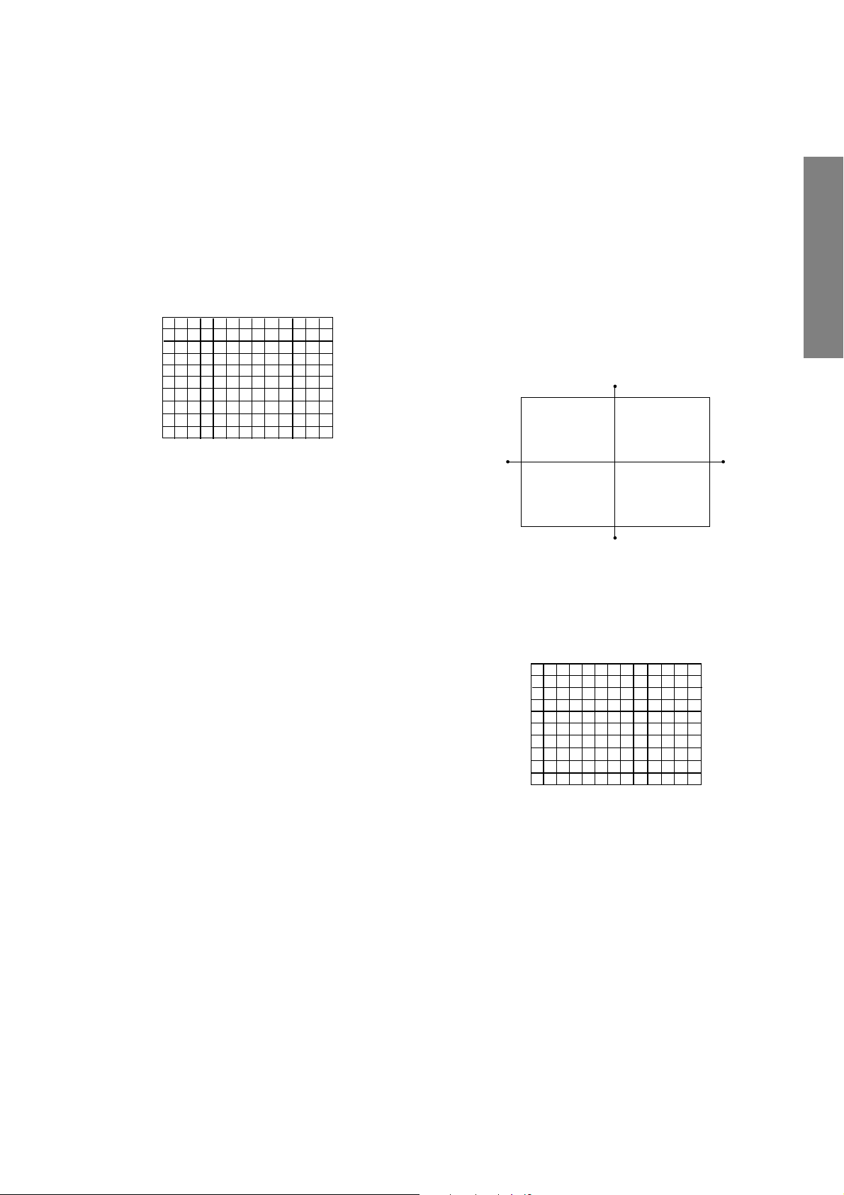
CENTERING ADJUSTMENT
1. Stretch a thread between two center of screen edge (top
and bottom, left and right).
GENERAL ADJUSTMENTS
Note: Normally the most clearly visible point of the scanning
line is the sharpest point of the Green focus, however as
the characteristics vary depending on the projection tube,
the sharpest focus points of the vertical and horizontal
lines may not match each other, thus when you turn the
focus VR, if the picture tends to be tremendously unstable
(rolls horizontally or vertically), adjust the balance of the
vertical and horizontal lines to its best position.
13. Check the GREEN focus of the whole screen and if
necessary repeat steps 10 and 11.
14. Fix the GREEN lens by tightening up its fixing screws.
15. Expose only BLUE by covering the RED and GREEN
lenses with caps.
16. Press a button on the remote controller in order to display
the internally-generated cross-hatch (See TEST SIGNAL
SELECTION on page 11.)
17. Loosen the BLUE lens fixing screws (refer to Fig. a), and
adjust the BLUE lens focus while observing the middle
and peripheral screen sections.
18. Press a button on the remote controller in order to display
the internally-generated black cross-hatch (See TEST SIGNAL SELECTION on page 11.)
19. Use the focus VR of “B” of the focus pack in order to adjust
the focus in the middle section of the screen to its sharpest
level.
(The point of the Blue focus becomes sharpest when the
brightness level of BLUE is lowest, the cross-hatch is
clearly visible.)
2. Select the adjustment mode. (See page 10.)
3. Press a button on the Remote Control to display the black
cross-hatch.
4. Adjust G centering magnet so that the cross-hatch pattern center comes to screen center.
5. Perform HEIGHT adjustment . (See page 14.)
6. Perform WIDTH adjustment. (See page 14.)
7. Check whole quality of green line.
8. Adjust R, B centering magnet so that the cross-hatch pattern center comes to screen center.
SPECIFIC INFORMATIONS
– 7 –
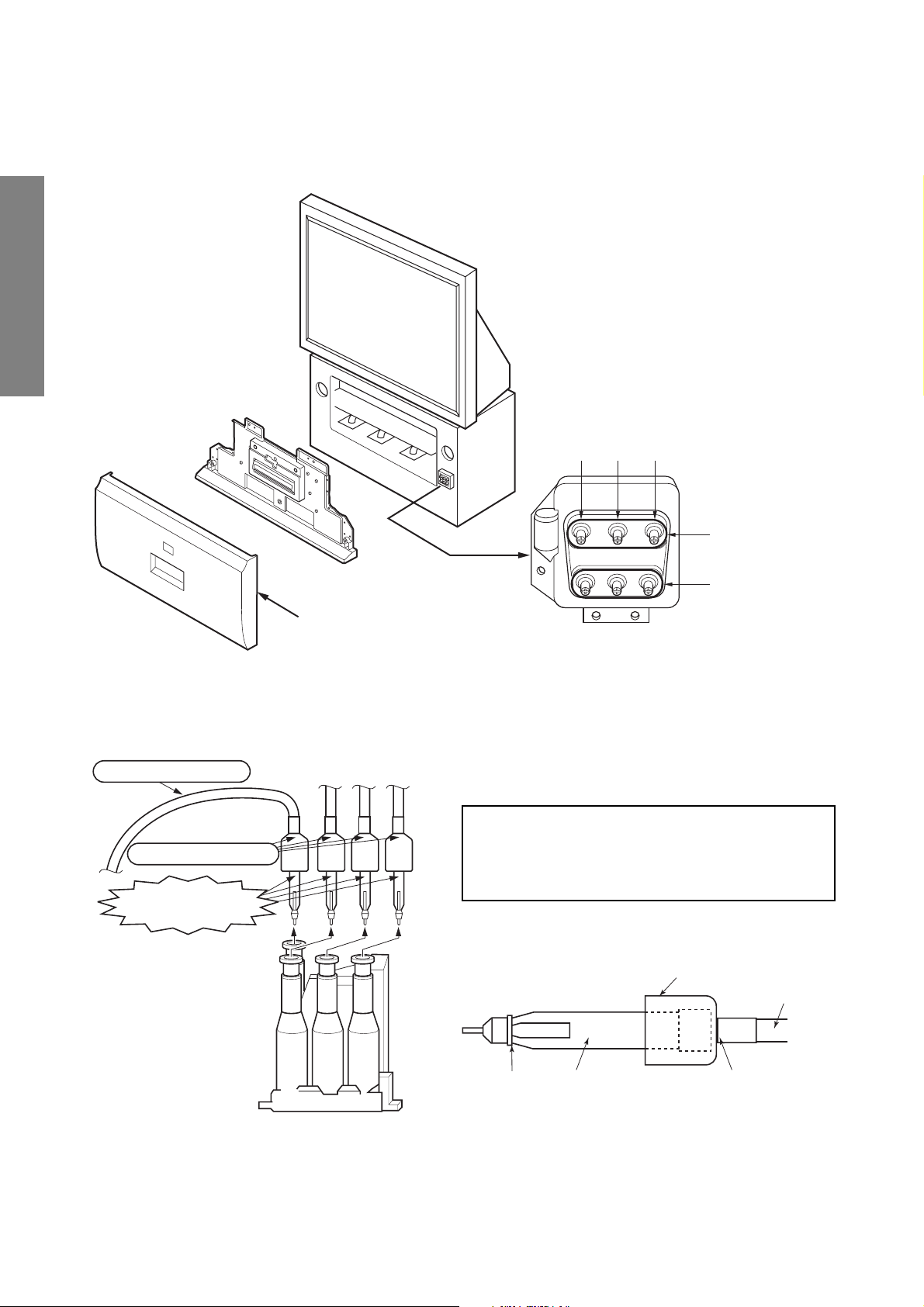
LOCATION OF SCREEN AND FOCUS VR’S
g
To remove the Speaker grille and Front panel.
GENERAL ADJUSTMENTS
Front grille
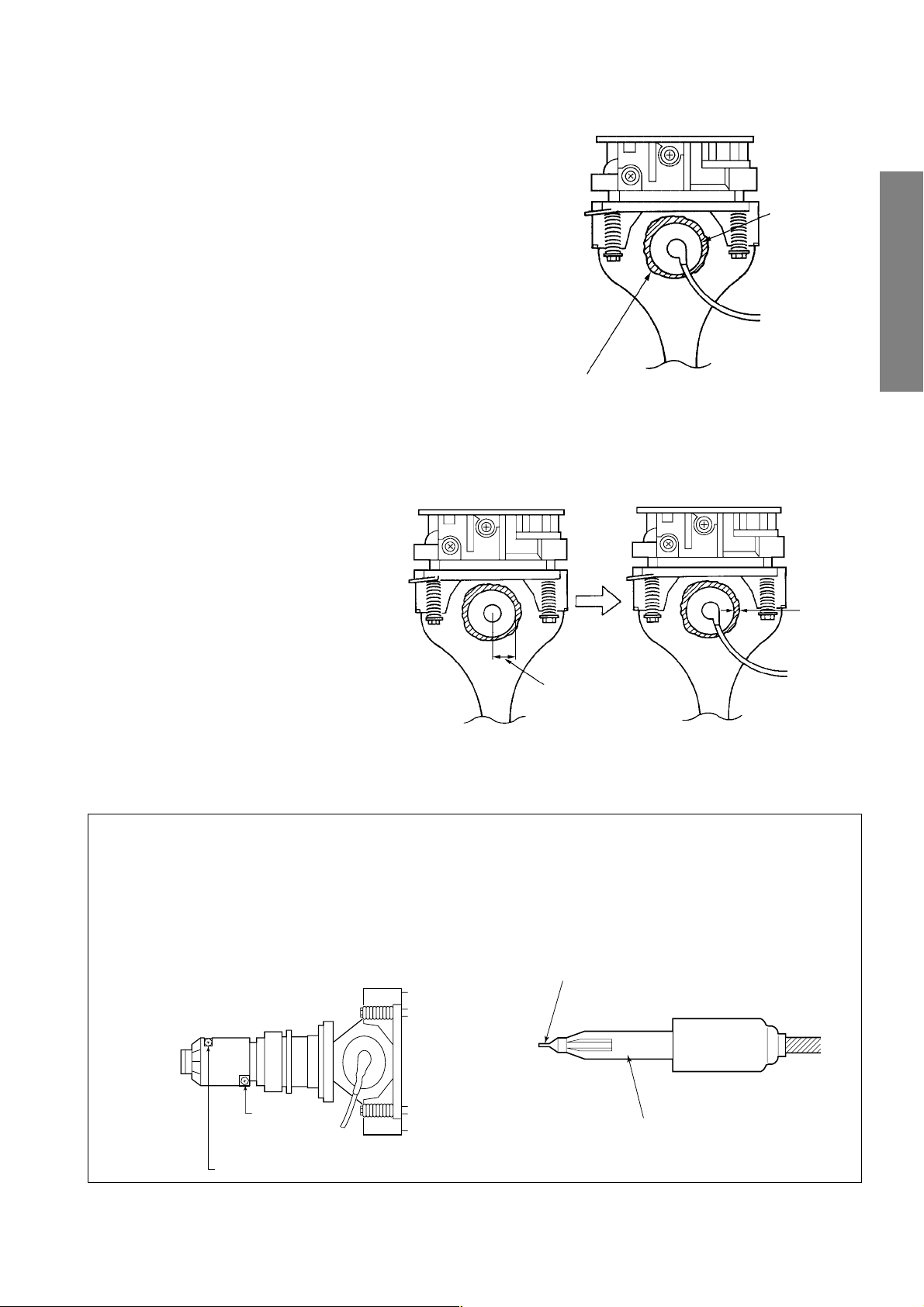
REPLACEMENT OF HIGH VOLTAGE CABLE
ANODE LEAD
RUBBER BOOT
LEAD HOLDER
B
1. When replacing Anode Lead or Anode Cap with new
one, remove Lead Holder from old lead as shown in figure below, and put it on new lead. Do not throw away
Lead Holder.
NOTE : THE LEAD HOLDER IS ATTACHED TO
TPA5011AH (Z450), BUT IS NOT ATTACHED
TO ANODE LEAD AND ANODE CAP. RUBBER
BOOT IS ATTACHED TO ANODE LEAD AND
ANODE CAP.
2. Detaching Lead Holder
RG
FOCUS VR's
SCREEN VR's
Fig. a
Z450 TPA5011AH
– 8 –
LOCK
RUBBER BOOT
LEAD HOLDER
. b
Fi
OLD
ANODE LEAD
or
ANODE CAP
Cut here rubber boot
and lead together to
detach Lead Holder.
WARNING: BEFORE SERVICING THIS CHASSIS, READ THE “X-RAY RADIATION PRECAUTION”, “SAFETY PRECAUTION” AND “PRODUCT SAFETY NOTICE” ON PAGE 3 OF THIS MANUAL.
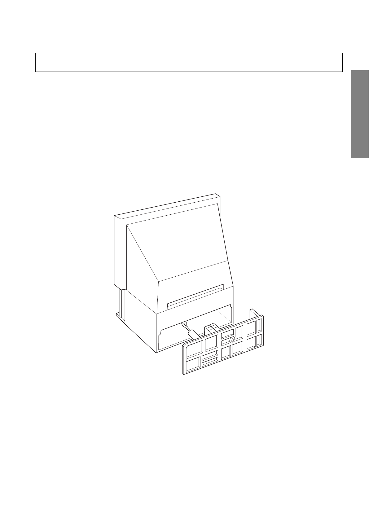
SERVICE POSITION
In order to assure the performance, processed wires shall be replaced after the repair work.
Work procedures are as follows:
1. Remove the back board.
2. Remove lead wires.
3. Draw out the chassis.
4. Rest the chassis against the back cabinet, chassis as shown bellow.
After repair work finished, replace it in the opposite procedure.
GENERAL ADJUSTMENTS
– 9 –
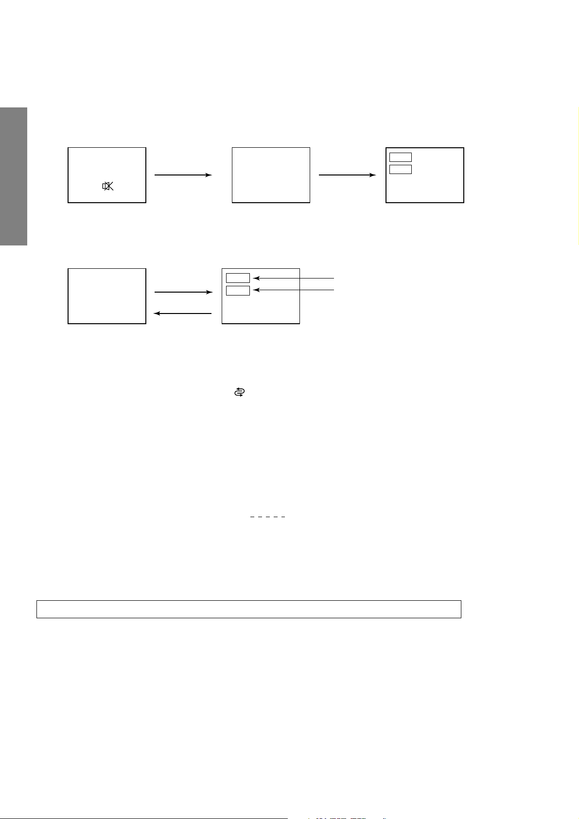
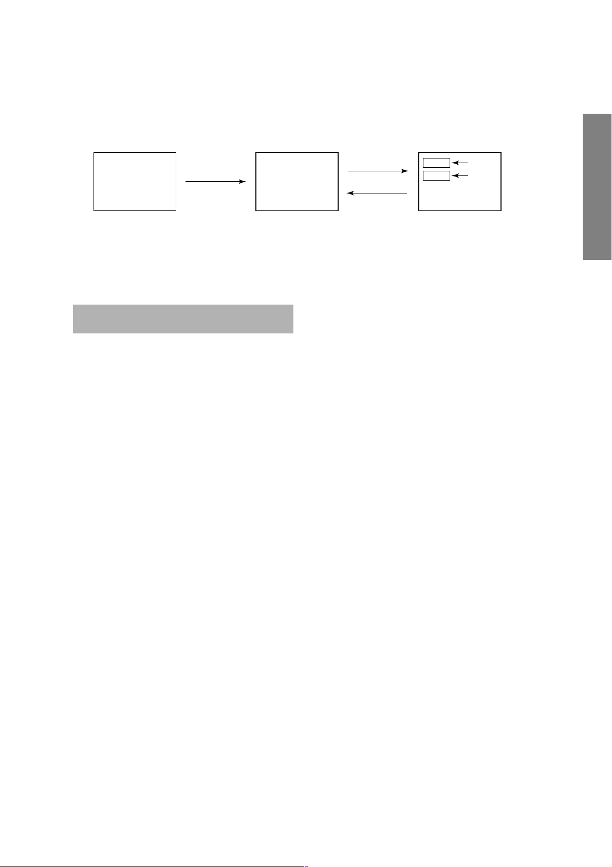
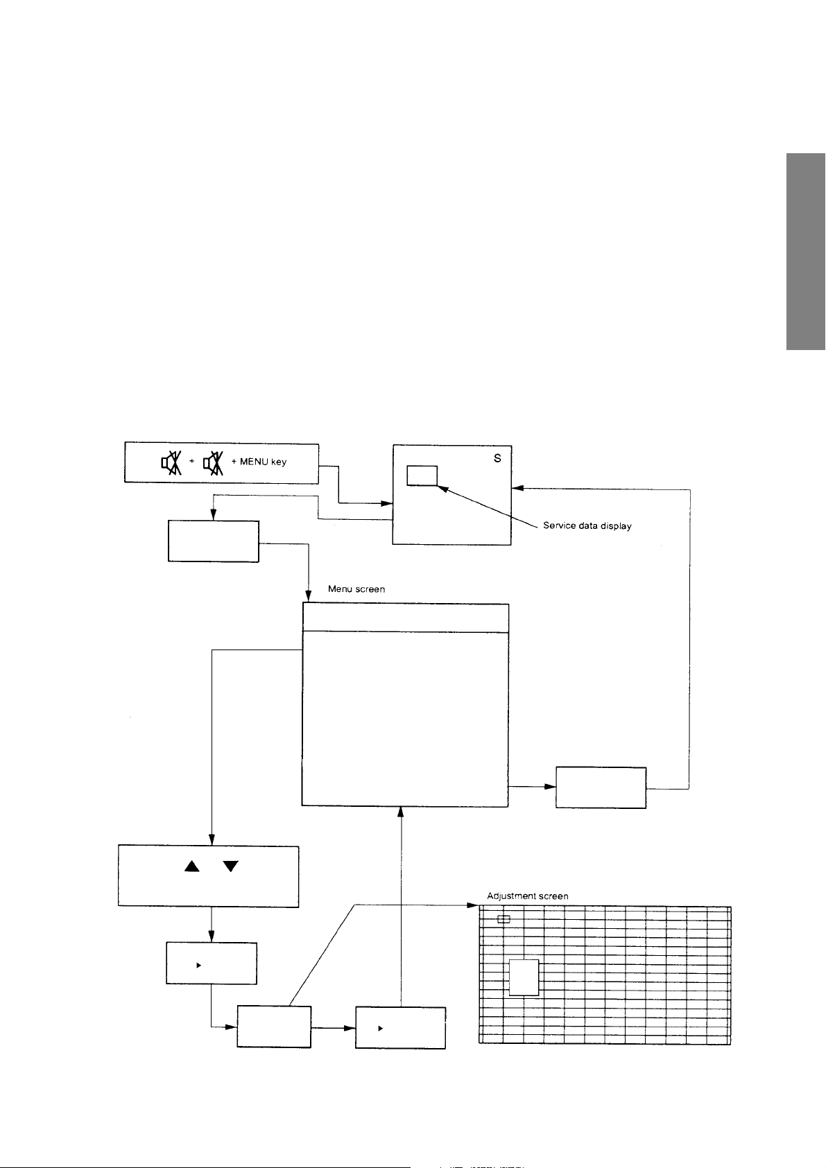
1. ENTERING TO SERVICE MODE
1) Press o button once on
Remote Control.
SERVICE MODE
2) Press o button again to
keep pressing.
3) While pressing the o button,
press MENU button on TV set.
or Sound Mute
GENERAL ADJUSTMENTS
2. DISPLAYING THE ADJUSTMENT MENU
1) Press MENU button on TV.
Service mode
S
3. KEY FUNCTION IN THE SERVICE MODE
The following key entry during display of adjustment menu provides special functions.
SPECIFIC INFORMATIONS
Screen adjustment mode ON/OFF: -/-- ( ) button (on Remote)
Test signal selection : a button (on Remote)
Selection of the adjustment items : Channel s/t (on TV or Remote)
Change of the data value : Volume ; +/– (on TV or Remote)
Adjustment menu mode ON/OFF : MENU button (on TV)
Initialization of the memory (QA02) : CALL + Channel button on TV (s)
Reset the count of operating protect
circuit to “00”: CALL + Channel button on TV (t)
“RCUT” selection : 1 button
“GCUT” selection : 2 button
“BCUT” selection : 3 button
“SCNT” selection : 4 button
“COLP” selection : 5 button
“TNTC” selection : 6 button
Convergence adj : YELLOW button
Self diagnostic display ON/OFF : 9 button
Press
Press
Adjustment mode
Item
Data
(Service mode display)
Item
Data
S
Color thickness correction
note: Displayed differently as shown below, de-
pending on the setting of the receiving color
system.
COLP (PAL)
COLC (NTSC)
COLS (SECAM)
CAUTION : Never try to perform initialization unless you have changed the memory IC.
– 10 –
4. SELECTING THE ADJUSTING ITEMS
1)Every pressing of CHANNEL s button in the service mode changes the adjustment items in the order of table-2.
(t button for reverse order)
Refer to table-2 for preset data of adjustment mode.
(See SETTING & ADJUSTING DATA on page 31)
5. ADJUSTING THE DATA
1) Pressing of VOLUME ; +/– button will change the value of data in the range from 00H to FFH. The variable range
depends on the adjusting item.
6. EXIT FROM SERVICE MODE
1) Pressing POWER button to turn off the TV once.
■ INITIALIZATION OF MEMORY DATA OF QA02
After replacing QA02, the following initialization is required.
1. Enter the service mode, then select any register item.
2. Press and hold the CALL button on the Remote, then press the CHANNEL s button on the TV. The initialization of QA02 has
been complated.
3. Check the picture carefully. If necessary, adjust any adjustment item above.
Perform “Auto tune” on the owner’s manual.
CAUTION: Never attempt to initialize the data unless QA02 has been replaced.
7. TEST SIGNAL SELECTION
1) Every pressing of a button on the Remote Control changes the built-in test patterns on screen as described below
in SERVICE MODE.
Signal off
NTSC signals (5 patterns)
PAL signals (5 patterns)
Signals Picture
• Red raster
• Green raster
• Blue raster
• All White
• Black cross-hatch
GENERAL ADJUSTMENTS
SPECIFIC INFORMATIONS
The signals marked with are not usable to display in the Test signal for some model.
*
– 11 –

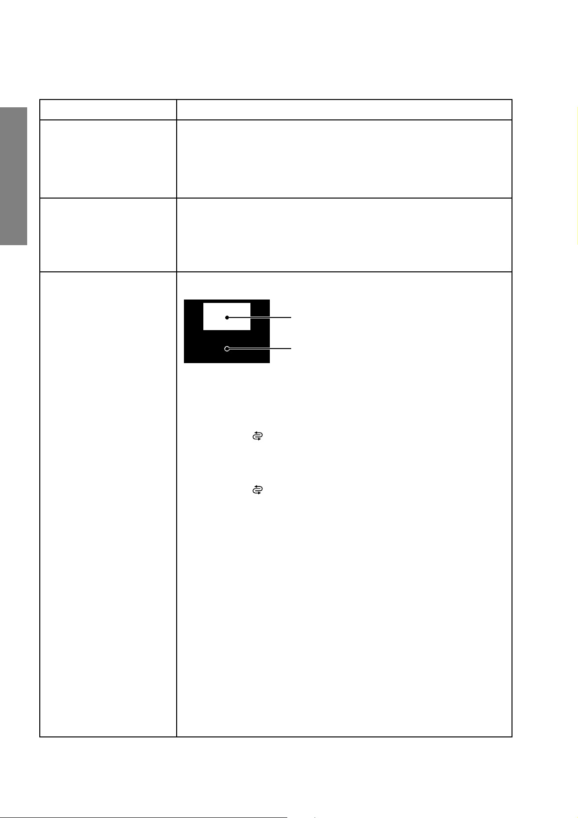
8. SELF DIAGNOSTIC FUNCTION
1) Press “9” button on Remote Control during display of adjustment menu in the service mode.
The diagnosis will begin to check if interface among IC’s are executed properly.
2) During diagnosis, the following displays are shown.
Indicated color of mode now selected : Green and Red
<SELF CHECK>
2300****
TIME : 000000
POWER : 00
BUS CONT : OK
BLOCK : UV V1 V2 V3 V4
V5
GENERAL ADJUSTMENTS
Part number of microcomputer (QA01)
Total hour of turn the TV on. (Unit: H)
Operation number of protecting circuit ----“00” is nor-
mal.
When indication is other than “00”, overcurrent apts to
flow, and circuit parts may possibly be damaged.
BUS CONT ----“OK” is normal.
When indication shows “Q uuu NG”, the device with
SPECIFIC INFORMATIONS
the number may possibly be damaged.
BLOCK
UV : TV reception mode
V1 : VIDEO 1 input mode (a1)
V2 : VIDEO 2 input mode (a2)
V3 : VIDEO 3 input mode
V4 : VIDEO 4 input mode
V5 : VIDEO 5 input mode
Indicated color of other modes : Black
Green : Normal
Red : The microcomputer operates to provide judgement
of no video signal. The red color is still indicated
though the signal is input, failure may exist in input
signal line including QV01.
NOTE: (1) In case that "on timer" indicator is blinking with
interval of 0.5 seconds; it means protecting
circuit (Current limiter) is operating, and circuit components may possibly be damaged.
Check related components.
(2) In case that "on timer" indicator is blinking with
interval of 1 second; Protecting circuit does
not operate, but a part of Bus line does not
operate normally. Check Bus line.
The items marked with are not usable to display in the SELF DIAGNOSTIC FUCTION for some model.
*
– 12 –
1. ENTERING TO DESIGN MODE
1) Select the Service mode.
DESIGN MODE
2) While pressing CALL button on Remote
and press MENU button on TV.
3) Press MENU button on TV.
S D
(Design mode) (Adjustment mode)
When QA02 is initialized, item “OPT3" of DESIGN MODE is set to the data of the representative model of this chassis family.
Therefore, because ON-SCREEN specification remains in the state of the representative of model. This model is required to
reset the data of item “OPT3".
2. SELECTING THE ADJUSTING ITEMS
Every pressing of CHANNEL t button in the design mode changes the adjustment items in the order of table-3.
(s button for reverse order)
Refer to table-3 for data of design mode.
(See SETTING & ADJUSTING DATA on page 31)
3. ADJUSTING THE DATA
Pressing of VOLUME s or t button will change the value of data.
Press
Press
ITEM
DATA
GENERAL ADJUSTMENTS
SPECIFIC INFORMATIONS
– 13 –
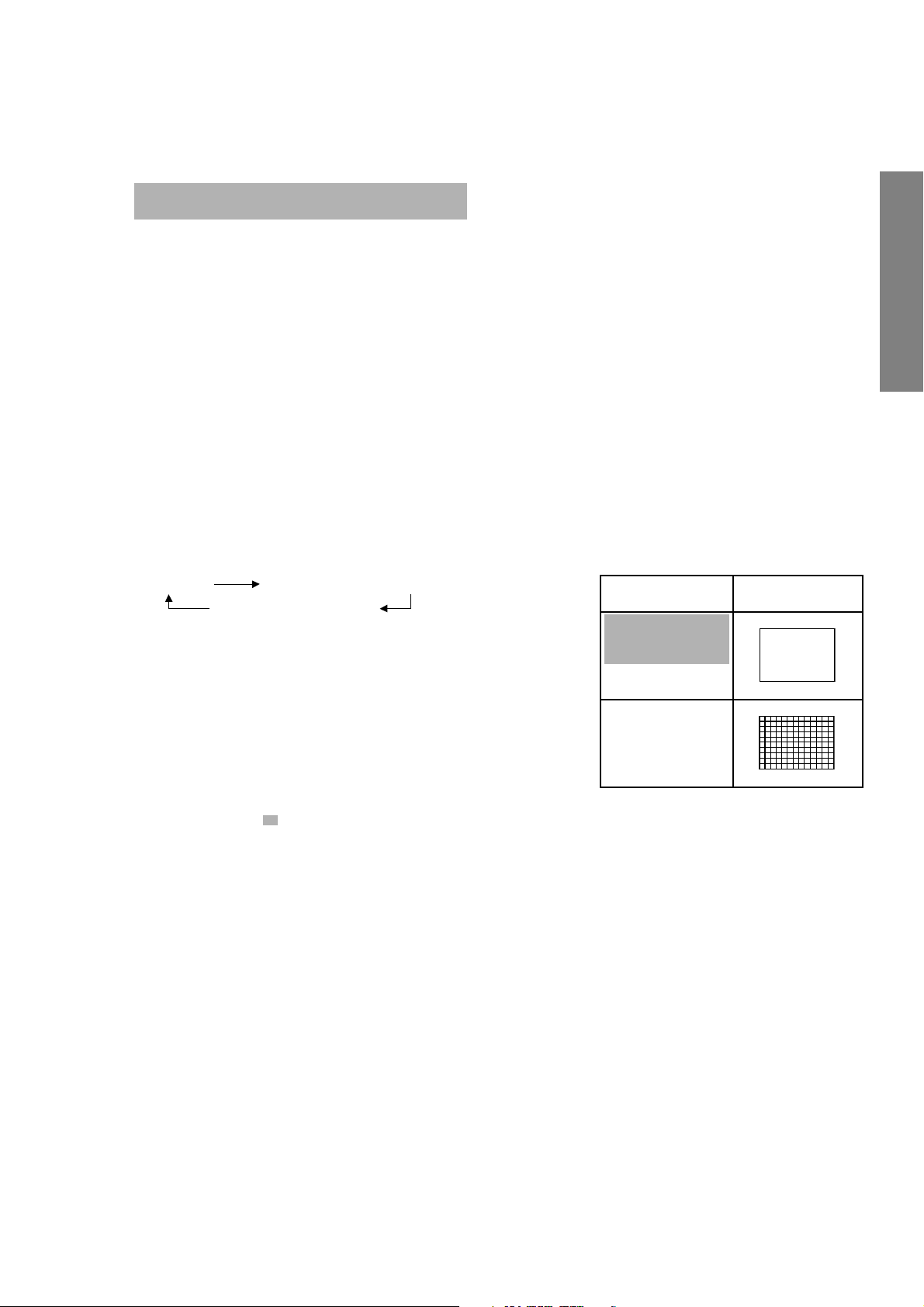
ELECTRICAL ADJUSTMENT
ITEM ADJUSTMENT PROCEDURE
WIDTH
(WID)
(Picture size wide)
HEIGHT
(HIT)
GENERAL ADJUSTMENTS
(Picture size wide)
WHITE BALANCE
(RCUT)
(GCUT)
(BCUT)
(RDRV)
(BDRV)
SPECIFIC INFORMATIONS
1. Call up the adjustment mode display, then select the item WID.
2. Press the VOLUME t button to get the picture so the left
or right edges of raster begins to lack.
3. Press the VOLUME s button to advance the data by 11
steps.
Note : Check the horizontal picture position is correct.
1. Call up the adjustment mode display, then select the item HIT.
2. Press the VOLUME t button to get the picture so the top or bottom of
raster begins to lack.
3. Press the VOLUME s button to advance the data by 9 steps.
Note : Check the vertical picture position is correct.
Black and White pattern
1. Set user control to reset position.
CONTRAST → Max
(
BRIGHTNESS, COLOR, TINT → Center.
2. Call up the adjustment mode display, then select the item RCUT.
3. Adjust the data of items RCUT, GCUT, and BCUT to "40H".
4. Press the -/-- ( ) button on Remote. (Y-MUTE : ON)
5. Gradually rotate R, G and B screen volume of FOCUS PAC clockwise or counterclockwise until the raster appears slightly on the CRT through the each lens,
and leave them.
(Lookin to the lens in order to check the raster.)
6. Press the -/-- (
7. Press the a button on Remote, and select the Black and White pattern.
8. Adjust the data of items RCUT, GCUT and BCUT for proper white-balanced
picture in low light area.
9. Adjust the data of items RDRV and BDRV for proper white-balanced picture in
high light area.
10. Check the white balance in both low and high light areas.
If necessary, perform again steps from 8 to 9.
) button on Remote. (Return to Normal Picture)
* There is not in the built-in test patterns.
It needs to prepare the pattern generator.
High light area
Adjust "RDRV" or "BDRV" to be white.
Low light area
Fine adjust "RCUT", "GCUT" or "BCUT" to be black.
)
– 14 –
C03P: Series (Reference factory adjustment)
TP-V
TP-G
Adjusting
standards
For details,
refer to [focus
adjusting
method]
introduced in
the next page.
8750k-0.002uv
8750k-0.002uv
).
2
).
2
Digital
voltmeter
GENERAL ADJUSTMENTS
2) Adjust after adjusting W/B, SCNT.
(PAL-I signal) SIGNAL unit white peak.
Audio system: I
(Y mute, DRV.CUT=40H)
adjust the screen VR to the point that starts lighting.
3) Directly observe the surface of Cathode Ray Tube and
4) Make above-mentioned adjustments for each tube of G, R,
SPECIFIC INFORMATIONS
and B.
Crosshatch 2) Use the jig and shade the CRT except the axes under
and B.
3) Make above-mentioned adjustments for each tube of G, R,
signal adjustment.
center WIDE mode signal adjustment signals.
Items Names Settings Input signals Measuring points Adjusting methods
BRTC Sub-bright Picture mode 1 Sub-bright Screen 1) Adjust the number of black collapsed lines of sub-bright 4 lines
SCNT Sub-contrast Picture mode 1 Sub-bright signal TP03 1) Adjust amplitude from the pedestal level up to the 0.7 (o-p)
center signal SIGNAL unit 2) Adjust the P-P value of the upper half.
COLP Sub-color Picture mode 1 Sub-bright TP02 1) Adjust the amplitude of the rainbow color bar. 0.25 V (p-p)
PAL (PAL)
COLS Sub-color Picture mode 1 SECAM TP02 1) Adjust the amplitude of the color bar. 0.52 V (p-p)
SECAM
center color bar SIGNAL unit
R-Y Black level color bar SIGNAL unit be aligned with the level of H.BLK.
SRY SECAM SECAM TP02 1) Adjust so that the level of black and white signal part can 0 mV
R-Y Black level color bar SIGNAL unit be aligned with the level of H.BLK.
SBY SECAM SECAM TP01 1) Adjust so that the level of black and white signal part can 0 mV
Screen Screen Factory screen CRT tubular 1) Darken the environment as much as possible. Point that
adjustment adjusting mode screen 2) Set to factory-set screen adjusting MODE. starts lighting
– 15 –
Focus Focus Picture mode 1 Retma signal Screen 1) Adjust to the best position by repeating electrical focus and
adjustment (PAL-I) adjustment optical focus adjustments.
RDRV Bright part Picture mode 1 Screen 1) Adjust the color temperature of the bright part (103cd/m
BDRV W/B WIDE mode adjustment
RCUT Dark part W/B Picture mode 1 Screen 1) Adjust the color temperature of the dark part (17cd/m
voltage DFS-100 Hz and TP-G and TP-G and adjust it to 0 mV by VCEN data.
BCUT WIDE mode adjustment
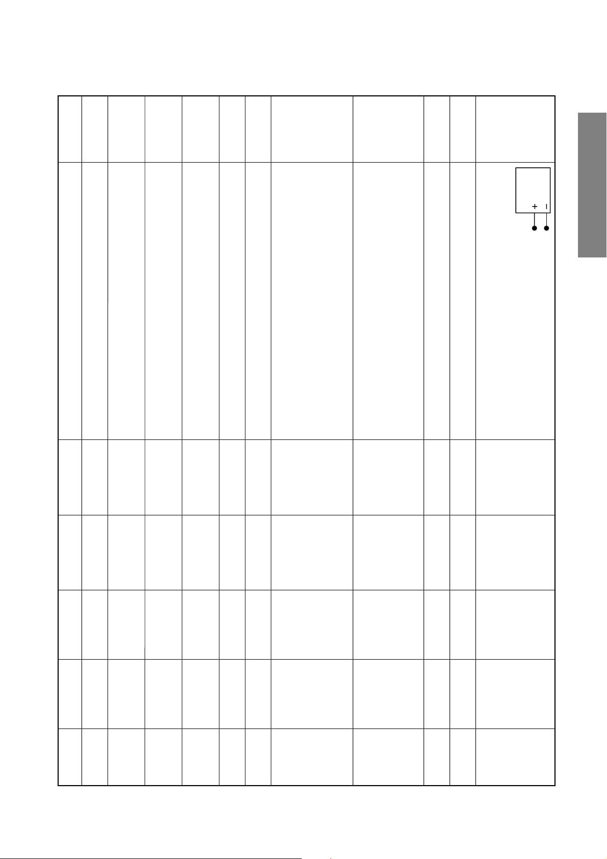
VCEN Midpoint Picture mode 1 Phillips Pattern Between TP-V 1) Connect a digital voltmeter between TP-V 0 ± 10mV
voltage (No designation on polarity of degital voltmeter)
adjustment
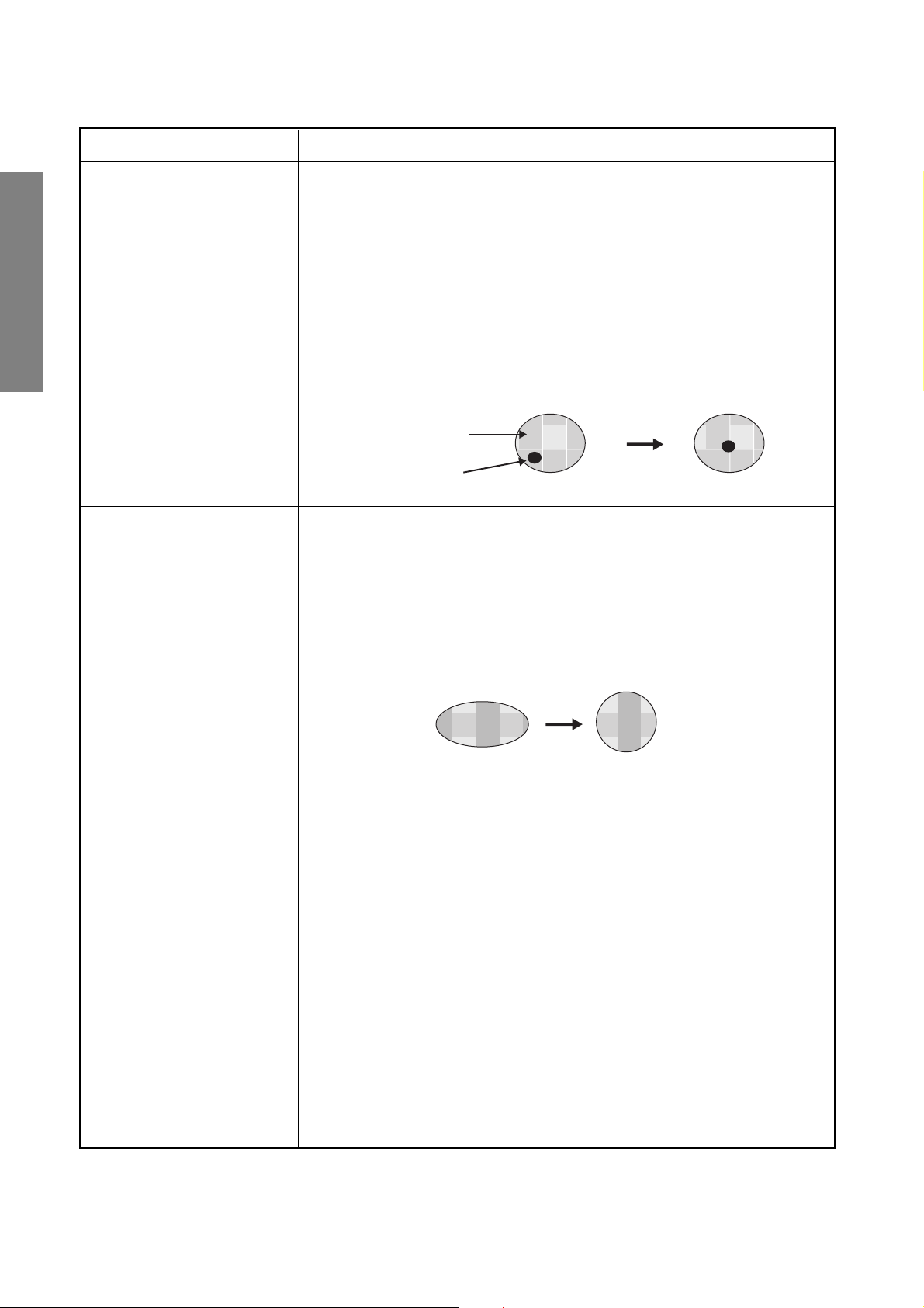
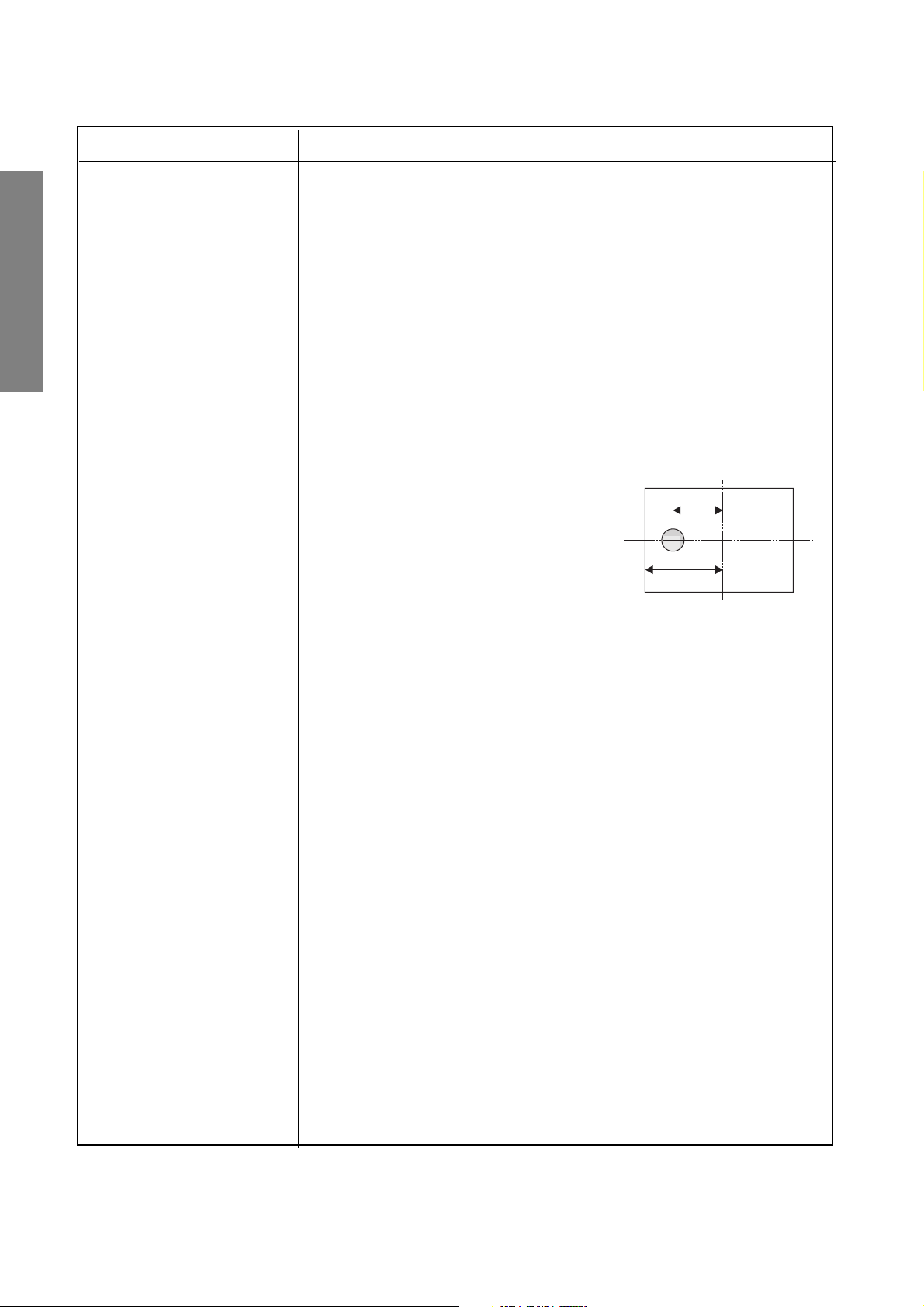
Green Alignment/Astigmatic Adjustments
Adjustment items Adjusting methods
Alignment Adjustment Procedures (Make this adjustment by using a lens cap. This adjustment should be
GENERAL ADJUSTMENTS
made after adjusting the electrical focus nd lens focus rough and making a
Centering Adjustment.)
1. Set the G monochrome by a lens cap.
2. Cancel the magnetic fields of bipolar, tetrapolar, hexapolar magnets.
3. Receive the image of dot pattern which is generated by the signal generator.
(White dot, Black background)
4. Turn the focus VR slightly left from the just focus point.
5. Adjust the bipolar magnet so that the dark brightness point is center of the light
bright area.
6. Make a just focus adjustment.
7. Receivethe image of Philips pattern, and re-adjust the centering.
8. Repeat the above items 4 to 7. Re-adjust those items if necessary.
Light area (flare)
Dark point
Astigmatic Adjustment
SPECIFIC INFORMATIONS
Procedures (Make this adjustment by using a lens cap.)
1. Set G monochrome by a lens cap.
2. Input the dot pattern (white dot and black backgroud).
3. Turn the Focus VR slightly right from the just focus point.
4. Adjust the tetrapolar magnet so that the fuzzy dot is a perfect circle.
5. Check and confirm that the shapes of flare are almost the same circle even if
turing the VR focus right and left.
6. Make a just focus adjustment.
7. Affix the magnet with adhesives.
Make adjustment so that the dot is a perfect circle.
– 16 –
Adjustment items Adjusting methods
Focus adjustment (Conditions)
- User adjustment: Dynamic mode, Cinema mode
- To be performed after centering magnet adjustment.
- Signal : Lens: R .... Crosshatch (PAL)
Electrical focus :
(Adjustment)
1. Common item
1) Make coarse adjustments in advance on the lens focus and electrical
focus of each R, G, and B tube.
2. G adjustment
1) Set to the G monochrome by lens cap.
2) Receive the image of crosshatch.
3) Adjust the G electric focus.
Adjust the G electrical focus by the focus volume of focus block (Z410)
so that the screen center will come to optimum focus. (Although the G
electrical focus is to be adjusted to allow the scanning lines in the center
of the screen to be seen most clealy, if G alignment and astigmatism are
inferior with the appearance of vertical and horizontal flares in the center
of and around the screen and if the lines become thicker, adjust to the
best point observing the entire screen.)
G.... Crosshatch (PAL)
B .... Crosshatch (PAL)
R .... Crosshatch (PAL)
G.... Crosshatch (PAL)
B .... Crosshatch (PAL)
GENERAL ADJUSTMENTS
SPECIFIC INFORMATIONS
4) Adjust the G lens focus.
Keep an eye on the center of the crosshatch pattern and adjust so that
the screen center will become clear.
As a rough guide to decrease unevenness, adjust so that red flares on
both sides of the crosshatch line will come to 1mm in thickness.
5) Repeat 3, 4, and attempt to further improve the focus quality.
– 17 –
Adjustment items Adjusting methods
Focus adjustment
GENERAL ADJUSTMENTS
SPECIFIC INFORMATIONS
Concerning items 1), 2), 3), and 5) of G adjustment, these are common to the ones
on the previous page.
3. R adjustment
1) Set to the R monochrome by lens cap.
2) Receive the image of the internal crosshatched pattern.
3) Adjust the R electrical focus.
Adjust by focus volume of the focus block (Z410) so that the screen center will
come to optimum focus.
4) Adjust the R lens focus.
Adjust so that the screen center will become the best.
5) Repeat 3, 4, and attempt to further improve the focus quality.
4. B adjustment
2/3L
1) Set to the B monochrome by lens cap.
2) Receive the image of internal crosshatch
pattern.
3) Adjust the B electrical focus.
Adjust the B electrical focus by using the focus VR on the focus block (Z410)
so that the scanning line is the most distinct at the point of 2/3L left side from
the screen center.
L
4) Adjust the B lens focus.
Pay attention to the border of the blue line and the black (background) in the vicinity of the screen center.
First of all, make coarse adjustments of the lens, and move the lens adjusting
screw to the right at the point being considered as the best focus. Then, the lines
of the border become clear. Check and confirm under the circumstance that a
flare appears. On the contrary, if the lens adjusting screw is moved to the left from
the situation, the flare will disappear, and at this point you will find a point from
which the borderline itself begins to go out of focus. Adjust to the very point where
the focus begins to go out.
– 18 –
Adjusting
standards
7 ± 1 flags
Adjusting methods
the centering magnet so that the center cross mark of the
dummy screen and the cross mark of the Phillips pattern
can overlap precisely.
This will be carried out individually for the tubes of R, G, and B.
Shorten the vertical amplitude by HIT data until the upper and
lower flags appear on the screen.
The amplitude should be balanced vertically. If not, adjust VLIN.
When VLIN is adjustd, adjust the screen position by the
centering magnet.
1) Adjust the vertical and horizontal screen positions using
(Caution) Do not move HPOS and VPOS data.
1)
2)
Lower the WID data in the beginning, and shorten the amplitude
Subsequently, lengthen the vertical amplitude by HIT data until
3)
horizontally until the left and right flags appear completely.
either upper or lower flag end is aligned with the screen end.
1)
The upper first one on the screen is to be hidden by the mask.
Lengthen the horizontal amplitude by WID data so that the
number of register marks will come to 7 in total (each 3.5 flags
2)
screen edge.
at the left and right sides).
1) Adjust the upper line of Philips Pattern is to be fited in with 16:9
The amplitude should be balanced vertically.
1)
2)
1) Adjust the 2.5th left register mark to the left screen edge.
screen edge.
1) Adjust the upper line of Philips Pattern is to be fited in with 16:9
GENERAL ADJUSTMENTS
Screen
Measuring points
Settings Input signals
Items Names
adjustment
Philips Pattern
(PAL-I)
Picture model
DFS-100Hz
Adjustment
of screen
position
Philips Pattern
(PAL-I)
Picture model
DFS-100Hz
CMUT-ON
Vertical
amplitude
adjustment
PAL
WIDE
HIT
VLIN
Screen
adjustment
Philips Pattern
(PAL-I)
Picture mode 1
DFS-100Hz
CMUT-ON
Horizontal
amplitude
adjustment
WID
Screen
adjustment
Philips Pattern
(PAL-I)
Picture mode 1
DFS-120Hz
mode
16:9 mode
CMUT-ON
Vertical
amplitude
adjustment
CHIT
Screen
adjustment
Monoscope
signal
Picture mode 1
DFS-120Hz
Vertical
amplitude
HIT2
LIN2
Screen
Monoscope
Picture mode 1
adjustment
NTSC
WID2 Horizontal
adjustment
signal
DFS-120Hz
amplitude
Screen
Monoscope
Picture mode 1
mode
Vertical
adjustment
NTSC
CHIT2
adjustment
signal
DFS-120Hz
mode
16:9 mode
amplitude
adjustment
NTSC
– 19 –
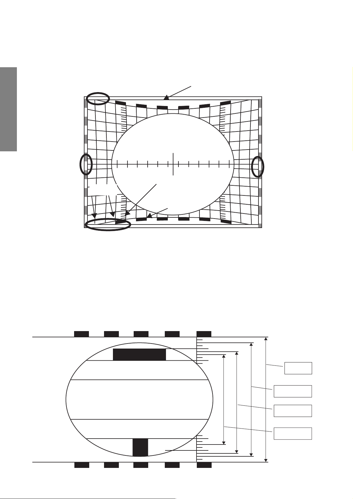
Deflection amplitude setting for 50PH36P (HIT/WID adjusting method under muted convergence)
∗ Green pattern under the muted convergence
(DFS-100Hz)
GENERAL ADJUSTMENTS
A
Horizontal amplitude: Left and right register marks of Philips pattern C + D = 7 (See A of the upper figure.)
Vertical amplitude: The point where the center between 1st and 2nd vertical line outer from the upper and lower register
B
3rd flag
0
0 point
1st flag
Castration border line
C
Screen edge
A
marks of Philips pattern is overlapped with flags contacts the screen edge. If the amplitude is uneven
horizontally and vertically, make HIT adjustment so that B shown in the upper left of the upper figure
comes to contact the screen edge.
Next, pay attention to the C point. Check and confirm that the castration border line contacts through
2nd line to 4th line outer from the lower register mark.
Vertical amplitude adjusting method for PAL/100Hz mode
1 Make adjustment on the basis of the upper screen.
2 Do not make VLIN adjustment for SUPERLIVE.
3 Screen adjusting range: ±1
WIDE
SUPERLIVE
SUBTITLE
CINEMA
– 20 –
1. SCREEN ADJUSTMENT
CONVERGENCE ADJUSTMENT
The adjustment is carried out on six screens:
1 PAL 100Hz Wide/4:3
2 PAL 100Hz Super live
3 PAL 100Hz Cinema
4 PAL 100Hz Subtitle/14:9
5 PAL Progressive all
6 NTSC Progressive all
When making the adjustments, feed an external signal to
make a synchronization.
1-1. Entering the Adjustment Menu
7 key
Note:
The convergence circuit is a circuit to eliminate screen distortion and can not make a drastic correction such as to correct
entire screen size. An excessive correction may actuate the
protection circuit. So a care will be necessary.
Before proceeding to the adjustment for each screen, always
perform the adjustments for vertical size (HIT) and horizontal
size (WID) with the main deflection data changed.
The menu order is 1~6 .... when the input signl is PAL. (In this
case item 7 is not selectable)
The menu order is 7 .... when the input signal is NTSC. (In this
case, item 1~6 are not selectable)
GENERAL ADJUSTMENTS
SPECIFIC INFORMATIONS
or
MENU Selection
+ key
Screen
adjustment
Conver adjust menu
1 ADJUST PAL 100HZ WIDE
2 PAL WIDE TO OTHERS
3 ADJUST PAL 100HZ S.LIVE
4 ADJUST PAL 100HZ CINEMA
5 ADJUST PAL 100HZ S.TITLE
6 ADJUST PAL Progressive
7 ADJUST NTSC Progressive
+ key
7 key
Fig. 1
– 21 –
 Loading...