

Page 1

SERVICE MANUAL
LCD Color Television
50L2333D(G), (B)
REVISED:02
50L2331D(G)
50L2337D(G), (B)
Page 2

REVISION HISTORY
REV
Date
Reason for Change
1
Jul/25/2013
- Addition of the 50L2333D(B) model
- Addition of "DESTINATION SETTING CHANGE"
2
Dec/19/2014
- Addition of "AFTER MAIN PCB REPLACEMENT".
- Updating of the Parts List (Exploded View page)
- Addition of the 50L2331D(G) and 50L2337D(G)/(B) model
- Addition of the location number (E322) of the power cord in
INTERCONNECT
- Updating of the Parts List (Exploded View)
- Addition of "PANEL IDENTIFICATION"
Page 3
CONTENTS
1
1
2
1. IMPORTANT NOTICE
2. GREEN PRODUCT PROCUREMENT
3. LEAD-FREE SOLDER
4. SAFETY INSTRUCTION
5. HOTEL MODE
6. COPYING HOTEL MODE SETTING
7. FIRMWARE UPDATING
8. INTERCONNECT
9. EXPLODED VIEW
10. PANEL IDENTIFICATION
11. AFTER MAIN P CB REPLA CEME NT
12. DESTINATION SETTING CHANGE
1
Page 4

IMPORTANT NOTICE
WARNING:
You are requested that you shall not modify or alter the information or data provided
herein without prior written consent by Toshiba. Toshiba shall not be liable to
anybody for any damages, losses, expenses or costs, if any, incurred in connection
with or as a result of such modification or alteration.
THE INFORMATION OR DATA HEREIN SHALL BE PROVIDED "AS IS" WITHOUT ANY
WARRANTY OF ANY KIND, EITHER EXPRESS OR IMPLIED WARRANTY OF
MERCHANTABILITY AND FITNESS FOR A PARTICULAR PURPOSE.
Toshiba shall not be liable for any damages, losses, expenses or costs, if any,
incurred in connection with or as a result of use of any information or data provided
herein.
Page 5

GREEN PRODUCT PROCUREMENT
The EC is actively promoting the WEEE & RoHS Directives that define standards for
recycling and reuse of Waste Electrical and Electronic Equipment and for the Restriction of
the use of certain Hazardous Substances. From July 1, 2006, the RoHS Directive will
prohibit any marketing of new products containing the restricted substances.
Increasing attention is given to issues related to the global environmental. Toshiba
Corporation recognizes environmental protection as a key management tasks, and is doing
its utmost to enhance and improve the quality and scope of its environmental activities. In
line with this, Toshiba proactively promotes Green Procurement, and seeks to purchase
and use products, parts and materials that have low environmental impacts.
Green procurement of parts is not only confined to manufacture. The same green parts
used in manufacture must also be used as replacement parts.
LEAD-FREE SOLDER
This product is manufactured using lead-free solder as a part of a movement within the
consumer products industry at large to be environmentally responsible. Lead-free solder
must be used in the servicing and repair of this product.
WARNING: This product is manufactured using lead free solder.
DO NOT USE LEAD BASED SOLDER TO REPAIR THIS PRODUCT!
The melting temperature of lead-free solder is higher than that of leaded solder by 30ºC to
40ºC (54ºF to 72ºF). Use of a soldering iron designed for lead-based solders to repair
product made with lead-free solder may result in damage to the component and or PCB
being soldered. Great care should be made to ensure high-quality soldering when servicing
this product especially when soldering large components, through-hole pins, and on PCBs
as the level of heat required to melt lead-free solder is high.
Page 6

(1/4)
SAFETY INSTRUCTION
WARNING: BEFORE SERVICING THIS CHASSIS, READ THE "SAFETY PRECAUTION"
AND "PRODUCT SAFETY NOTICE" INSTRUCTIONS BELOW.
Safety Precaution
WARNING: SERVICING SHOULD NOT BE ATTEMPTED BY ANYONE UNFAMILIAR WITH
THE NECESSARY PRECAUTIONS ON THIS RECEIVER. THE FOLLOWING ARE THE
NECESSARY PRECAUTIONS TO BE OBSERVED BEFORE SERVICING THIS CHASSIS.
1. An isolation transformer should be connected in the power line between the receiver
and the AC line before any service is performed on the receiver.
2. Always disconnect the power plug before any disassembling of the product. It may
result in electrical shock.
3. When replacing a chassis in the cabinet, always be certain that all the protective
devices are put back in place, such as nonmetallic control knobs, insulating covers,
shields, isolation resistor-capacitor network, etc.
4. Always keep tools, components of the product, etc away from the children, These items
may cause injury to children.
5. Depending on the model, use an isolation transformer or wear suitable gloves when
servicing with the power on, and disconnect the power plug to avoid electrical shock
when replacing parts. In some cases, alternating current is also impressed in the
chassis, so electrical shock is possible if the chassis is contacted with the power on.
6. Always use the replacement parts specified for the particular model when making
repairs. The parts used in products require special safety characteristics such as
inflammability, voltage resistance, etc. therefore, use only replacement parts that have
these same characteristics. Use only the specified parts when the
in the circuit diagram or parts list.
7. Parts mounting and routing dressing of wirings should be the same as that used
originally. For safety purposes, insulating materials such as isolation tube or tape are
sometimes used and printed circuit boards are sometimes mounted floating. Also make
sure that wirings is routed and clamped to avoid parts that generate heat and which use
high voltage. Always follow the manufactured wiring routes / dressings.
mark is indicated
Page 7
(2/4)
8. Always ensure that all internal wirings are in accordance before re-assembling the
external casing after a repairing completed. Do not allow internal wiring to be pinched
by cabinets, panels, etc. Any error in reassembly or wiring can result in electrical
leakage, flame, etc., and may be hazardous.
9. NEVER remodel the product in any way. Remodeling can result in improper operation,
malfunction, or electrical leakage and flame, which may be hazardous.
10. Touch current check. (After completing the work, measure touch current to prevent an
electric shock.)
Plug the AC cord directly into the AC outlet. Do NOT use an isolation transformer for
this check.
Connect a measuring network for touch currents between each exposed metallic part
on the set and a good earth ground such as a water pipe.
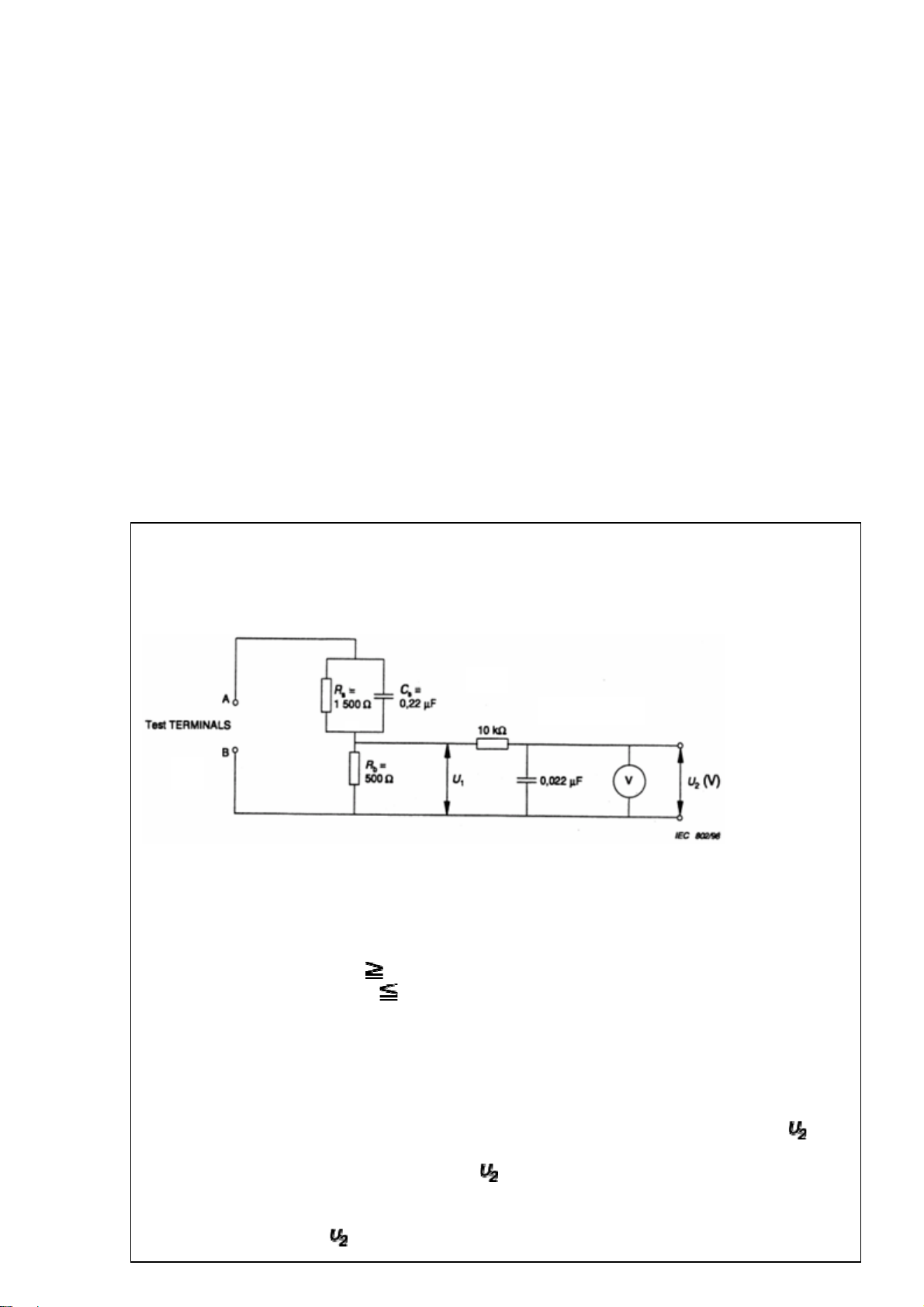
Annex D
(normative)
Measuring network for TOUCH CURRENTS
Resistance values in orms (Ω).
V: Voltmeter or oscilloscope
(r.m.s. or peak reading)
Input resistance :
1 MΩ
Input capacitance : 200 pF
Frequency range : 15 Hz to 1 MHz and d.c. respectively
Note: Appropriate measures should be taken to obtain the correct value in case of non
sinusoidal waveforms.
The measuring instrument is calibrated by comparing the frequency factor of with
the solid line in figure F.2 of IEC 60990 at various frequencies. A calibration curve is
constructed showing the deviation of
from the ideal curve as a function of
frequency.
TOUCH CURRENT =
/ 500 (peak value).
Page 8
(3/4)
The potential at any point (TOUCH CURRENT) expressed as voltage and does
not exceed the following value:
The part or contact of a TERMINAL is not HAZARDOUS LIVE if:
a) The open-circuit voltage should not exceed 35 V (peak) a.c. or 60 V d.c. or, if a) is
not met.
b)
The measurement of the TOUCH CURRENT shall be carried out in accordance
with IEC 60990, with the measuring network described in Annex D of this
standard.
The TOUCH CURRENT expressed as voltages and , does not exceed the
following values:
- for a.c. : = 35 V (peak) and = 0.35 V (peak);
- for d.c. : = 1.0 V
Note: The limit values of = 0.35 V (peak) for a.c. and = 1.0 V for d.c.
correspond to the values 0.7 mA (peak) a.c. and 2.0 mA d.c.
Page 9

(4/4)
Product Safety Notice
Many electrical and mechanical parts in this chassis have special safety-related characteristics.
These characteristics are often passed unnoticed by a visual inspection and the protection
afforded by them cannot necessarily be obtained by using replacement components rated for
higher voltage, wattage, etc. Replacement parts which have these special safety
characteristics are identified in this manual and its supplements; electrical components having
such features are identified by the international hazard symbols on the schematic diagram and
the parts list.
Before replacing any of these components, read the parts list in this manual carefully. The use
of substitute replacement parts which do not have the same safety characteristics as specified
in the parts list may create electrical shock, fire, or other hazards.
Page 10

HOTEL MODE
(1/5)
1
Function Setting *off(normal set)
Hotel Mode On/Off Off/On Off Hotel mode enable
1
Panel Lock Off/On Off Inhibit all buttons which are on TV body
2
Panel Lock W/O Input Selector Keys. Off/On Off Inhibit all buttons which are on TV body only disable input key
3
Disable Remote Control Off/On Off Inhibit the remote control.
4
Disable All Menu Off/On Off
5
Disable Setup Menu Off/On Off Inhibit set up menu
6
*On: hotel mode on
*On: not available Side key
*On: not available Side key only disable input key
*Setting is enable at the Service mode.
*On: not available remote control
*On: All of user menu will be disabled.
*Off: All of user menu will work normally.
*On: set up menu Inhibit
Information
Setup Menu W/O Lang. Off/On Off Inhibit display set up menu except for language
setting.
7
*There is only language setting at the Setup menu.
*On: only lang. display at setup menu.
Page 11

Max Volume Setting 0~100[dec] 100 Max volume control
(2/5)
8
Digital Tuner Off/On On DTV source selection depends on Digital Tuner setting.
9
USB Port Off/On On MEDIA source selection depends on USB port setting.
10
TV to USB NO/YES NO It will clone the data of TV to USB disk. The data
11
USB to TV NO/YES NO It will clone the data of USB disk to TV. The data
12
Disable NIT Update Off/On Off *On: enable NIT update
13
Max vol setting Method:
Setting 100 volume, and turning and choice this value.
*On: enable DTV
*Off: hide DTV
*On: enable MEDIA in inputs menu
*Off: hide MEDIA in inputs menu
*
Off (Enable 5V): Disable USB, but enable the 5V power.
includes user setting, the setting of hotel mode and
channel table.
includes user setting, the setting of hotel mode and
channel table.
*Off: disable NIT update
Detect SCART On / Off On
14
ON: Pin8 will go on normal operation and it is going to switch
between sources automatically.
Off: Pin8 is ignored and the automatic source switching would
be enabled.
Page 12
(3/5)
2
1 Fixed Pos/Video
2 Fixed Volume
3 Fixed Picture Mode
Off/ On(AC)/
On
ATV(0~99)/SCART/AV/
YPBPR/HDMI1/HDMI2/
PC/DTV
Off/On Off Remote control power button on or TV power switch(on side
0~100[dec] (normal:50)
Off/On Off Remote control power button on or TV power
0:Dynamic(Default)
1:Standard
2:Mild
Off Remote control power button on or TV power switch
(on side body) on, then display goes to fixed POS/Video
(= nealy equal #9)
*On: fixed pos/video set
*On (AC): TV tunes to preset “Pos/Video” (channel or input) only
when AC power is applied. When TV is powered on by power
button, tune to the last channel or input.
*TV, Component, AV,…, PC,HDMI,….Off
TV:1~255[dec] (normal:0)
DTV: depends on channel auto tuning
body) on , then forced volume setting
*101~ : not available
switch(on side body) on, then picture mode is selected
*On: Fixed selectable Pic.
4 Welcome Message
3:Movie
4:Memory
Off/On Off Remote control power button on or TV power
Page 13

(4/5)
1:Default
2:8 Sec.
3:15 Sec.
Update Welcome Message YES/NO NO It will update the logo, when TV on the new logo show.
5
Teletext Off/On On Teletext functions are depend on Teletext setting
6
ATV/DTV P+/P- Off/On Off *On: enable ATV/DTV P+/P-
7
switch(on side body) on, then fixed "Welcome to our hotel"
Message is displayed.
'Until first operation' means that first event for TV
occur (ex. Ch up).
Using USB, user replaces the user original message with the
*
default welcome message.
As below is message, the file limitation items:
1. File format should be JPG file.
2. JPG Resolution <= 1360 x 768.
3. JPG file size < 64KB.
4. JPG file name is “Hotel_Logo.jpg”.
*On: enable Teletext functions and operation
*Off: disable Teletext functions and operation
*Off: disable ATV/DTV P+/P
TV Power Disabled/
8
Reset Menu YES/NO NO Set to default all setting in Hotel mode menu
9
On/ Standby
Disabled
*Disabled: TV returns to previous Standby/On state when AC
power is applied.
*On: Power TV on when AC power is applied.
*Standby: Put TV in Standby when AC power is applied.
Page 14

How to enter Hotel Mode.
1) Press “MUTE” button on the remote, and display [mute].
2) Within 2 sec, press “MUTE” button on the remote again, and hold the button down for 3 sec.
3) Then, press “INPUT” button on the TV side. Then hotel mode menu will appear.
How to exit Hotel mode.
Turn the TV power off
(5/5)
Page 15

Copying Hotel Mode Setting
TV to USB:
TV to USB:
Copying a BIN file into USB flash.
Copying a BIN file into USB flash.
(1/4)
USB to TV:
USB to TV:
Copying a BIN file into TV.
Copying a BIN file into TV.
Page 16

Copying Hotel Mode Setting
TV to USB Step :
1. Insert USB flash disk into TV USB port.
2. Please press “MUTE” key twice (MUTE icon disappear) ,
at the same time, press “SOURCE” by keypad for a while.
->“Hotel Menu” will come out.
3. Select the item “TV to USB” and press Left or Right
button to choose “YES”. Then press “OK” button.
->The hotel settings will copy into USB disk with file name
(2/4)
HOTEL_xxx23xxx.BIN
4. Once copy is finished. The OSD message “Please
wait...” will disappear then shown "OK! " message.
Page 17

Copying Hotel Mode Setting
USB to TV Step (method 1) :
1. Insert USB disk with available file into TV USB port.
2. Please press “MUTE” key twice (MUTE icon disappear) , at
the same time, press “SOURCE” by keypad for a while.
->“Hotel Menu” will come out.
3. Selecting the item “USB to TV ” and press Left or Right
button to choose “YES”. Then press “OK” button.
(3/4)
->The hotel settings will copy from USB to TV with file name
HOTEL_xxx23xxx.BIN.
4. Once copy is finished. The OSD message “Please wait...”
will disappear then shown "Please remove USB memory, then
TV will be reset automatically" message.
Page 18

(4/4)
Copying Hotel Mode Setting
USB to TV Step (method 2) :
1. Insert USB disk with available file into TV USB port.
2. Please reboot (AC Off/On) TV to update hotel settings
automatically.
->the set will shown “Hotel Mode Settings Update Please Wait”.
3. The OSD message “Please wait...” will disappear then shown
“Update is finished .Please remove USB memory, then TV will be
reset automatically.”
4. Please remove USB disk then turn AC Off/On to reboot TV.
The new settings will be active.
Page 19

Firmware Upgrade – USB
1. Copying a firmware BIN file to
USB disk. (root directory)
2. Plug in USB disk to TV USB
port.
3. Reboot (AC Off/On) TV to
update F/W automatically.
4. During firmware upgrade will
have display a OSD on LCD
(1/2)
screen and power status LED
will be blinking.
5. When F/W upgrade is finished,
a message on screen will be
shown then unplug USB disk.
6. TV will be reset automatically.
1
Page 20

Definition of Firmware file name
File name: xxx23xxx_001_REV00.bin.
xx: for all TV size.
x23xxx: model series.
001 : firmware version ex 001 is 0.01, 100 is 1.00
(2/2)
REV00: fixed for revision 00
2
Page 21

E270
IR_BORAD
POWER BOARD
PANEL (LED B/L)
E260
LED_BORAD
E344
E340
E346
1
(For (B) model)
E320
E322
PANEL (T-CON)
E310
75033899 (RA)
75033900 (RB)
CN2 CN1 CN14
CN3 2 12V 13 +12V_Normal 2 PANEL_VCC
1 L2 Cathode 3 12V 12 +12V_Normal 3 PANEL_VCC
2 NC 4 GND 11 GND 4 PANEL_VCC
3 L2 Anode 5 GND 10 GND 5 RANEL_VCC
4 NC 6 NC 9 GND 6 RANEL_VCC
5 L1 Cathode 7 GND 8 +5V_Standby 7 GND
6 NC 8 5VS 7 +5V_Standby 8 GND
7 L1 Anode 9 5VS 6 +5V_Standby 9 RXA0+
E250
1 GND 4 Ring_G 37 RXB4+
2 LED_Bri 5 LED-Brighness 38 RXB43 Ring_Red 6 GND 39 BRIGHT_ADJ
4 Ring_Green 7 +3.3V_Normal 40 OCP_OUTPUT_PWM
1 +3.3V_Standby_IR
2 RC_IR
3 SCL
4 SDA
5 +3.3V_Normal_ALS
6 GND
1 12V 14 +12V_Normal 1 PANEL_VCC
10 5VS 5 SCANNING_BL_EN 10 RXA011 GND 4 ACDetect 11 RXA1+
12 ACD 3 OCP_OUTPUT_PWM 12 RXA113 POWER_ON 2 BL_EN 13 RXA2+
14 BL_ON_OFF 1 12V_EN 14 RXA215 NC 15 GND
16 PWM1 16 GND
E200
MAIN BOARD
1 +3.3V_Standby 34 RXBCK2 IRIN 35 RXB3+
3 Ring_R 36 RXB3-
CN3 33 RXBCK+
17 RXACK18 RXACK+
19 RXA320 RXA3+
21 RXA4+
22 RXA423 GND
24 GND
25 RXB0+
26 RXB027 RXB1+
28 RXB129 RXB2+
30 RXB231 GND
32 GND
E342
8 MI2C-SCL
9 MI2C-SDA
10 GND
CN13
1 SPK_L+
2 SPK_L3 SPK_R+
4 SPK_R-
Speaker
Speaker
Page 22

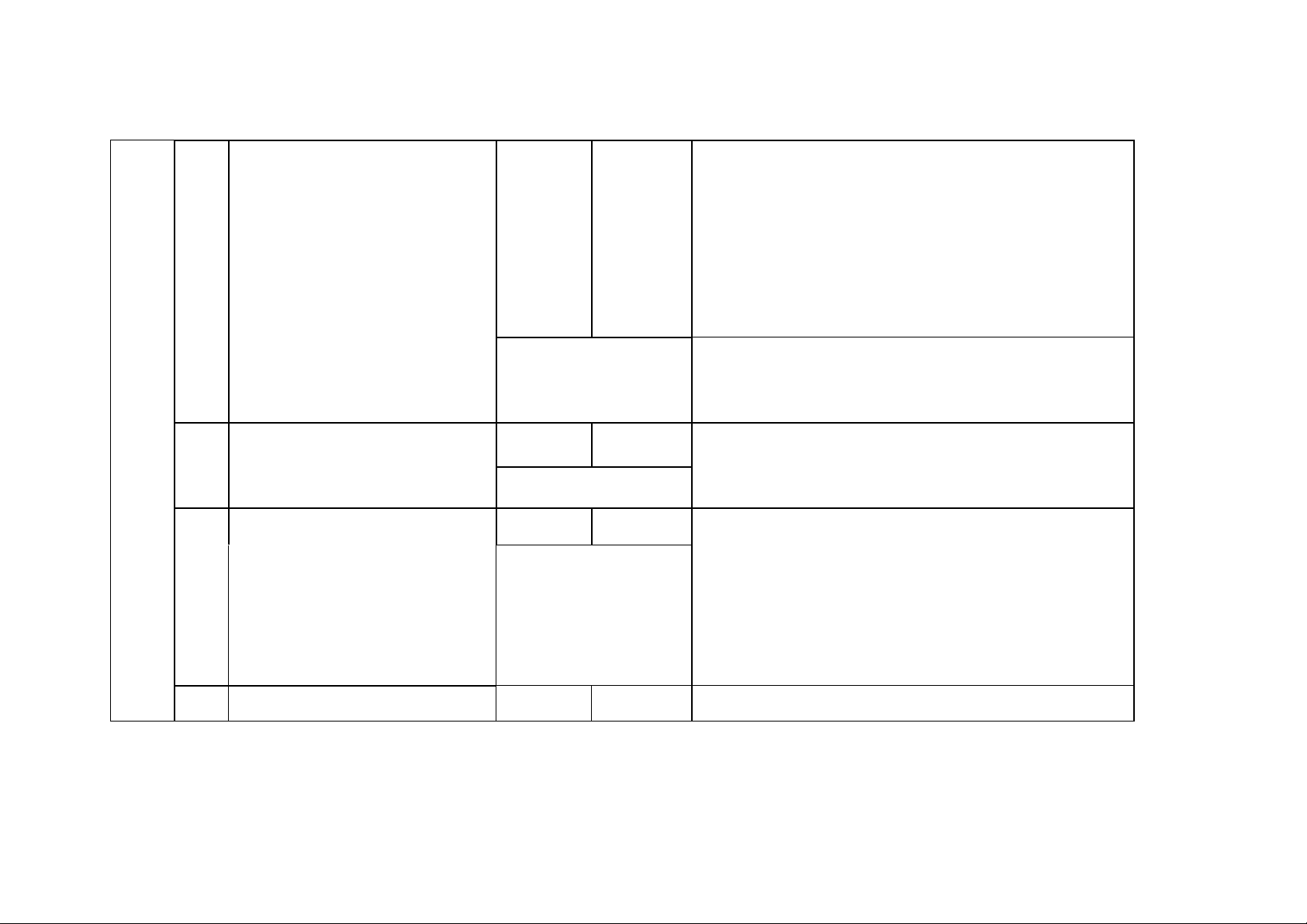
Exploded View
)
t
r
50L2333D/50L2331D/50L2337D
1
Note:
Please see PPL put on WebPRESS for the latest information or
other parts.
SAFETY PRECAUTION
The parts identified by mark
are critical for safety. Replace only
with part number specified. The
mounting position of replacement
is to be identical with originals.
The substitute replacement parts
which do not have the same safety
characteristics as specified in the
parts list may create shock, fire or
other hazards.
50L2333D(G)/(B),50L2331D(G),50L2337D(G)(B
No. Location
1+2+3
1
5
6
1
9
10
2
11
12
2
13
14+15
2
1
16+17+18+(19-2)
33
34
Toshiba
Service Par
E100 75033887 13EB-43B0601 FRONT COVER (FRONT BEZEL)
E106 75034305 13EB-43Q0W11 SUPPORT FOR SMALL BOARD
E300 75032896 LCD PANEL, LG, LC500DUE-SFR1
E250 75033897 0433-008C000 POWER BOARD ASSY
E200 75033896 9C-EB40M01H0 MAIN BOARD ASSY
E201 75037598 9C-EB40M0330 MAIN BOARD ASSY, WITHOUT TUNER
E140 SIDE KEY BEZEL ASSY
E330 75029565 04A4-012X000 SPEAKER (LEFT AND RIGHT)
E110 75035513 13EB-43Q1211 BACK COVER ASSY
E150 NECK ASSY
E120 STAND ASSY
E260 75033758 9C-EB40S0250 LED BOARD ASSY
E270 75033759 9C-EB40S0270 IR BOARD ASSY
75033892 13EB-43B0H01
75033893 13EB-43B0A01
75033894 13EB-43B0901
75033895 13EB-43B0K01
75035511 13EB-43B0C01
75036649 13EB-43B0P11
1
ODM Partne
Part
Description
Page 23

PANEL IDENTIFICATION
A
Serial No. part printed on Rating Label
Panel Identification Code
1
Marking Marking Marking
BKT
CLU
DMV
ENW
FPX
GQY
HRZ
Panel Vendor
AUO
CMO
IPS
JS
Panel Vendor
SAMSUNG
LPL/LGD
Panel Vendor
SHARP
Page 24

(1/1)
AFTER MAIN PCB REPLACEMENT
The following setting must be checked after PCB replacement to make sure, that PCB
setting corresponds to the panel type:
1. Enter Factory Menu:
- MENU
- Applications
- Sleep Timer + “2766”
2. Go to page 3 and select the proper panel type (take care of the full panel name, not only
panel vendor name).
Panel type can be found on the panel serial number sticker.
3. Press EXIT to leave the factory mode (please make sure you have selected the proper
panel type, before you press EXIT !).
4. If the proper panel type was set, TV will come up with proper picture after TV restart.
PLEASE TAKE CARE: set may come up with NO PICTURE at all when wrong panel was
selected and it will be very difficult/impossible to adjust the proper settings afterwards.
Page 25

DESTINATION SETTING CHANGE
Whenever replacing the Main PCB with new one, perform this procedure.
1. IR Key MENU → APPLICATIONS → Sleep Timer → OK.
2. When display _ _ : _ 0 input 4 numbers 2766.
The Factory menu will display.
3. Move to Tag "3" by Right/Left Arrow key on the Remote.
4. Select "Model Type" cell.
Select the appropriate model type by Right/Left Arrow key on the Remote.
5.
6. Select "Reset to Def".
7. Select "Yes" and press "OK" button on the Remote.
Page 26

TOSHIBA LIFESTYLE PRODUCTS & SERVICES CORPORATION
2-9, Suehiro-Cho, Ome-Shi, Tokyo 198-8710, Japan
REV. 02
Dec/19/2014
Page 27

5
4
3
2
1
CONTENTS
SCHEMATIC Name
D D
01.Contents & History
02.TV System Power Budget
03.MB Block Diagram
04.DC to DC
05.MSD8841-3A3D&USB&AUDIO
06.MSD8841-DDR&LVDS&GPIO
07.MSD8841_POWER
08.MSD8841-CI&TFE&TS&NAND
C C
09.MEMORY DDR3
10.PCMCIA CONN
11.HDMI and MHL
SHEET
1
2
3
4
5
6
7
8
9
10
11
REVISION HISTORY
Author VerDate
1.002012/08/27 For SR stage.
2012/09/14
Jeff/Jerry
Jeff/Jerry 1.01 For SR2 stage.
2012/10/20 Jeff/Jerry 1.02 For ER stage.
2012/11/07 Jeff/Jerry 1.03 For ER2 stage.
Jeff/Jerry 1.03a For PR stage.2012/11/21
Comments
12.VGA
13.COMPONENT and AV
14.SCART
15.SPEAKER&EARPHONE AMP
16.TUNER
B B
17.LVDS
12
13
14
15
16
17
18.SPDIF 18
19.USB
20.NAND FLASH
21.Ethernet CONN
22.MSB1230
23.IR_ALS
19
20
21
22
23
A A
Contents&History
Contents&History
Title :
Title :
Title :
Engineer:
Engineer:
MAIN BOARD
MAIN BOARD
MAIN BOARD
Size Project Name
Size Project Name
Size Project Name
L2300
L2300
B
B
B
Date: Sheet of
Date: Sheet of
5
4
3
2
Date: Sheet of
L2300
Engineer:
1
Contents&History
Jeff Y Hsiao/Jerry Lo
Jeff Y Hsiao/Jerry Lo
Jeff Y Hsiao/Jerry Lo
Rev
Rev
Rev
1.03a
1.03a
1.03a
1 23Thursday, December 20, 2012
1 23Thursday, December 20, 2012
1 23Thursday, December 20, 2012
Page 28

5
4
3
2
1
TV System Power Budget Block Diagram
AC 220~240
PSU Unit
32"/39"/50"
D D
C C
B B
+5V_Standby
+12V_Normal
LIPS
32WX/32FHD/39FHD/50FHD
LED Driver
+12V_Normal
GPIO_Panel_VCC_ON
Amp efficiency:85% , Devition 5%
+12V_Normal
GPIO_Panel_VCC_ON
Amp efficiency:85% , Devition 5%
+12V_Normal
GPIO_Panel_VCC_ON
Amp efficiency:85% , Devition 5%
PANEL_VCC
PANEL_VCC
PANEL_VCC
1.3A
1.3A
1.3A
GPIO_12V_EN
GPIO_OCP_OUTPUT_PWM
GPIO_BL_EN
ACDetect
SCANNING_BL_EN
Panel _Tcon0.7A
32WX/32FHD
AMP(7W+7W)
Panel _Tcon0.7A
39FHD
AMP(7W+7W)
Panel _Tcon0.7A
50FHD
AMP(7W+7W)
+5V_Standby
3947mA
1307mA
NORMAL_PWR_CTL
330mA
+5V_Standby
Enable_Control
0.046mA
410mA
+3.3V_Normal
Enable_Control
((1340mA/1000)*1.2)/(0.8)/5= 0.402
1900mA
U1
LDO
RT9043-GB
U27 MHL to HDMI
MSG1200
Power on Max. current= 0.046mA
Standby Max. current= 0.046mA
U6
DC/DC MSD8841BX_BGA20x20
TPS5432DDAR
GPIO_USB1_PWR_SW
GPIO_PCM_5V_CTL
PS_CTRL#
+5V_Normal
1047mA
Enable_Control
240mA
10mA
10mA
+3.3V_Standby
+1.2V_Normal
U2
DC/DC
TPS5432DDAR
U17
LDO
APE1117AK-HF
SPDIF_OUT CIRCUIT
SC_CVBS_OUT CIRCUIT
56mA
330mA
20mA
45mA
96mA
85mA
15mA
10mA
1339mA
USB_5V
500mA(Min).
VCC-PCMCIA
500mA(Min).
+5V_HDMIC
900mA(Max).
+3.3V_Normal
1047mA
TUNER_3.3V
240mA
U7
MSD8841BX_BGA20x20
AVDD_ALIVE(ball=N7)= 17.31mA
AVDD_DVI(ball=L7,K7)= 18.64mA
AVDD_DMPLL(ball=P6)= 6.01mA
AVDD_MPLL(ball=M8)= 13.24mA
Power on Max. current=
Standby Max. current=
U8
G690H293T73UF
Power on Max. current=
Standby Max. current=
U11
W25Q64FVSSIG
Power on Max. current=
Standby Max. current=
U27 MHL to HDMI
MSG1200
Power on Max. current=
Standby Max. current=
U3
LDO
RT9043-GB
TU1
TUNER
SUT_RE221
55.2mA
2.912mA
Reset IC
20mA
SPI Flash
45mA
0.05mA
95.12mA
1.12mA
+1.2V_Standby_MHL U27 MHL to HDMI
85mA
IR_ALS Board
Power on Max. current=
Standby Max. current=
15mA
LED_Board
Power on Max. current=
Standby Max. current=
10mA
U7
VDDC (ball=G9,H9,K10,K11,L10,M12,M13,
N12,P14,P15,R10,R14,R15,T10)= 1266.25mA
DVDDC(ball=M14)(DVDD_DDR)= 55.5mA
AVDDLV_USB(ball=K12)= 1.08mA
AVDDL_MOD(ball=R16)= 7.8mA
AVDD11_ETH(ball=L11)= 0.67mA
AVDD1P1(ball=P10)= 7.7mA
Power on Max. current= 1339mA
USB
PCMCIA
MHL
MSG1200
Power on Max. current=
Standby Max. current=
85mA
0.58mA
50mA
110mA
Enable_Control
200mA
Enable_Control
30mA
20mA
4mA
83mA
25mA
DEMOD
Enable_Control
80mA
445mA
Enable_Control
+5V_Normal
DT2_2.5V
400mA
Enable_Control
+5V_Normal
U7
MSD8841BX_BGA20x20
VDDP(ball=R19,T19)= 8.59mA
AVDD_AU(ball=T7)= 17.32mA
AVDD_EAR(ball=R7)= 5.08mA
AVDD_LPLL(ball=W17,W18)=18.19mA
Power on Max. current= 49.18mA
U5
LDO
RT9043-GB
U4
DC/DC
RT8059GJ5
((530mA/1000)*1.5)/(0.8)/5= 0.198
H27U2G8F2C
VCC1(Pin12)
VCC2(Pin37)
Power on Max. current=
pull high Resistor
Power on Max. current=
Power on Max. current=
U16 Audio
TAS5707L
TAS5707L= 83mA
Power on Max. current=
U14
DRV632PWR
VDD(Pin 9)
Power on Max. current=
U21
LDO
RT9043-GB
U21
LDO
RT9025_25PSP
U22
LDO
RT9025_25PSP
+2.5V_Normal
105.24mA
+1.5V_Normal
530mA
NAND FlashU18
30mA
20mA
Headphone
Amplifier
4mA
Power
Amplifier
83mA
Line Driver
25mA
105.24mA
U24
MSB1230-LF
AVDD_SAR_T2(Pin33)
55mA
DT2_2.5V
443mA
AVDD33_ADC_T2(Pin36)
AVDD_MPLL_T2(Pin43)
AVDD_APLL_TS/SDR_T2(Pin47)
VDD33_T2(Pin7,18,28,31,50,53,60)
Power on Max. current=
25mA
U23
EN25F20-100GCP
Power on Max. current=
43mA
DT2_1.2V
400mA
U7
MSD8841BX_BGA20x20
AVDD_ADC(ball=V8,W7,W8)= 36.2mA
AVDD25_PGA(ball=W11)= 0.01mA
AVDD_REF(ball=W9)= 0.43mA
AVDD_LAN(ball=W14)= 15.3mA
AVDD_MOD(ball=V16,W16)= 53.3mA
Power on Max. current= 105.24mA
U19
U7
MSD8841BX_BGA20x20
AVDD_DDR0(ball=J17,K15,K16,L15)=
AVDD_DDR1(ball=K17,L17,M17,L16)=
Power on Max. current= 110mA
U12
H5TQ2G63DFR-PBC
VDD1..9(ball=N1,R1,B2,K2,G7,K8,D9,N9,R9)
VDDQ1..9(ball=A1,C1,F1,D2,H2,A8,C9,E9,H9)
Power on Max. current=
U13
H5TQ1G63DFR-PBC
VDD1..9(ball=N1,R1,B2,K2,G7,K8,D9,N9,R9)
VDDQ1..9(ball=A1,C1,F1,D2,H2,A8,C9,E9,H9)
Power on Max. current=
U24
MSB1230-LF
AVDD25_ADC_T2(pin42)
Power on Max. current= 43mA
U24
MSB1230-LF
VDDC1(Pin9)
VDDC2(Pin20)
VDDC3(Pin30)
VDDC4(Pin51)
VDDC5(Pin59)
Power on Max. current= 400mA
TS21C_HF
210mA
210mA
DDR3 Memory
DDR3 Memory
55mA
SPI_Flash
25mA
57.5mA
52.5mA
A A
TV System Power Budget
TV System Power Budget
TV System Power Budget
Title :
Title :
Title :
Jeff Y Hsiao/Jerry Lo
Jeff Y Hsiao/Jerry Lo
Jeff Y Hsiao/Jerry Lo
Engineer:
Engineer:
L2300
L2300
L2300
Engineer:
Rev
Rev
Rev
1.03a
1.03a
1.03a
2 23Thursday, December 20, 2012
2 23Thursday, December 20, 2012
2 23Thursday, December 20, 2012
MAIN BOARD
MAIN BOARD
MAIN BOARD
Size Project Name
Size Project Name
Size Project Name
D
D
D
Date: Sheet of
Date: Sheet of
5
4
3
2
Date: Sheet of
1
Page 29

5
4
3
2
1
TS0
DVB-T/T2/C
DIF
PCMCIA SLOT
TS1
Silcon
D D
Tuner
SPI Flash
2Mbit
MSB-1230
Demod
Tuner I2C BUS
TS
DDR BUS
DDR3 2GBit
DDR BUS
DDR3 1GBit
SPI FLASH BUS
Tuner I2C BUS
2G DDR3 Vender:
1st:
2nd:
Hynix H5TQ2G63DFR-PBC
DDR3-1600 11-11-11/ 64MB*16
Samsung K4B2G1646E-BCK0000
DDR3-1600 11-11-11/ 64MB*16
1G DDR3 Vender:
1st:
2nd:
Hynix H5TQ1G63DFR-PBC
DDR3-1600 11-11-11/ 64MB*16
Samsung K4B1G1646G-BGK0
DDR3-1600 11-11-11/ 64MB*16
RGB-In/H/V/DDC
VGA
L/R-In
SPI FLASH BUS
VGA Phone Jack
CEC
C C
HDMI 1
HDMI ---ARC
TDMS-A In/DDC
CEC
NAND FLASH BUS
SPI Flash
64MBit
NAND Flash
2GBit
CEC
HDMI 2
HDMI 3
HDMI 4
CEC
CEC
TDMS/CBUS
MHL
MSG1200
TDMS-B In/DDC
MSD8841BX
TDMS-C In/DDC
2 CH LVDS
Panel Unit
TDMS-D In/DDC
1st:
2nd:
1st:
2nd:
Windbond W25Q64FVSSIG
Hynix H27U2G8F2C
Toshiba TC58NVG1S3ETA00
Ethernet-Tx/Rx
L/R-Out
AV Out
B B
SCART(Full)
RGB In/AV In
L/R-In
YPbPr In
Component
L/R-In
AMP
DVR632
L/R OUT
I2S BUS
I2C BUS
TS21C_HF
TPA6132
RJ-45
Earphone
SPEAKERTAS5707L
AV In
Composite
Input+L/R
L/R-In
DP0/DM0
USB 0
A A
USB 1(SIDE)
DP1/DM1
SPDIF_Out
SPDIF out
5
4
3
SAR I/F
IR In
I2C BUS
LED I/F
Power KEY
IR/ALS Board
LED Board
2
"+" KEY "-" KEY P/V/AV KEY
Title :
Title :
Title :
Engineer:
Engineer:
MAIN BOARD
MAIN BOARD
MAIN BOARD
Size Project Name
Size Project Name
Size Project Name
L2300
L2300
B
B
B
Date: Sheet of
Date: Sheet of
Date: Sheet of
L2300
Engineer:
Block Diagram
Block Diagram
Block Diagram
Jeff Y Hsiao/Jerry Lo
Jeff Y Hsiao/Jerry Lo
Jeff Y Hsiao/Jerry Lo
3 23Thursday, December 20, 2012
3 23Thursday, December 20, 2012
1
3 23Thursday, December 20, 2012
Rev
Rev
Rev
1.03a
1.03a
1.03a
Page 30

5
CN1
14
13
12
11
10
9
8
7
D D
6
5
4
3
2
1
WAFER_HD_1X14P
FB1 120Ohm
FB2 120Ohm
FB3 120Ohm
FB4 120Ohm
NC
C352
12
1000PF/50V
C347
12
22PF/50V
21
21
+5V_Standby
21
21
NC
C2
C11
12
12
0.1UF/16V
1000PF/50V
C12
12
C3
12
10UF/10V
12
12
22PF/50V
R8
R14
4.7KOHM
47KOHM
C6
C5
12
12
0.1UF/16V
1000PF/50V
R144 0 Ohm
R2 0 Ohm
R554 33 OHM
R556 33 OHMNC
R555 33 OHM
12
R15
4.7KOHM
+12V_Normal
NC
C429
C8
12
12
4.7UF/25V
0.1UF/16V
1 2
1 2
1 2
1 2
1 2
4
C9
12
0.1UF/16V
SCANNING_BL_EN 6
ACDetect 6
OCP_OUTPUT_PWM 17
BL_EN 6
FRC_BL_EN 17
12V_EN 6
+5V_Standby +3.3V_Standby
C13
1UF/16V
12
C14
0.1UF/16V
12
3
U1 RT9043-GB
1
VIN
12
R12
12KOhm
12
R16
10KOhm
NC
12
C25
0.1UF/16V
2
GND
3
EN
VOUT
FB
5
4
R13
180KOHM
R17
100KOHM
2
G1
1
NP_NC
2
GND1
12
12
12
C15
1UF/16V
12
C16
0.1UF/16V
3
GND2
4
GND3
C315D157N
G2
1
NP_NC
2
GND1
3
GND2
4
GND3
C315DO169x130n
GND8
GND7
GND6
GND5
GND4
GND8
GND7
GND6
GND5
GND4
9
8
7
6
5
9
8
7
6
5
1
1
2
3
4
C315D130N
1
2
3
4
C315D130N
G3
NP_NC
GND1
GND2
GND3
G4
NP_NC
GND1
GND2
GND3
GND8
GND7
GND6
GND5
GND4
GND8
GND7
GND6
GND5
GND4
9
8
7
6
5
9
8
7
6
5
+5V_Standby
C C
B B
+3.3V_Normal
12
A A
NORMAL_PWR_CTL4,6
C40
10UF/10V
FB35
120Ohm
12
C36
0.1UF/16V
C332
0.1UF/16V
1 2
R420
56KOhm
C451
1UF/16V
2 3
12
21
12
12
C324
C325
10UF/10V
0.1UF/16V
12
R428
56KOhm
+5V_Normal
12
R32
10KOhm
12
R33
10KOhm
12
C44
2.2UF/10V
12
Q18
AP2307GN
S
2
1
1
12
3
C
B
1
E
2
U4A
1
PGOOD
2
EN
3
VIN
4
VDD
RT9025_25PSP_12VIA
U4B
10
GND3
11
GND4
12
GND5
13
GND6
14
GND7
15
GND8
RT9025_25PSP_12VIA
D
3
12
G
R421
56KOhm
Q19
PMBS3904
GND10
GND11
GND12
GND13
GND14
C326
0.1UF/16V
GND2
GND1
VOUT
GND9
+5V_Normal
ADJ
NC
16
17
18
19
20
21
12
U6
1
BOOT
2
VIN
3
PH
4
GND1
TPS5432DDAR
12
C43
0.1UF/16V
+5V_Normal
12
12
C91
0.22UF/25V
GND2
COMP
VSENSE
R95
12KOHM
R98
10KOhm
9
8
SS
7
EN
6
5
C38
330PF/50V
1 2
R31
12KOHM
1 2
R37
24KOHM
U5 RT9043-GB
R131
0 Ohm
1
2
3
12
VIN
GND
EN
Pd:0.4W
NORMAL_PWR_CTL 4,6
R36
C28
1UF/16V
C45
0.01UF/50V
12
C29
12
R28
12
C46
12
12
12
0.1UF/16V
2.05KOhm
0.01UF/50V
10KOhm
1 2
R38
22KOHM
+3.3V_Normal
12
NC
C48
0.22UF/25V
12
12
12
NC
R39
10KOhm
NC
R40
22KOHM
C47
12
0.1UF/16V
VOUT
FB
5
4
R27
110KOHM
1 2
R35
100KOHM
12
C93
0.1UF/16V
C153
10UF/10V
12
C96
0.1UF/16V
R30 51KOHM
1 2
R34 56KOHM
12
9
8
7
6
5
R96
0 Ohm
12
2 1
12
L3
2.2uH
NC
C157
22UF/6.3V
+1.5V_Normal
12
12
C235
510mA
12
12
C41
10UF/10V
U15
1
BOOT
2
VIN
3
PH
4
GND1
+3.3V_Normal
12
C158
22UF/6.3V
0.1UF/16V
12
C37
0.1UF/16V
GND2
COMP
VSENSE
TPS5432DDAR
R130
49.9 OHM
1 2
C95
220PF/50V
1 2
R101
20KOhm
1 2
R100
6.49KOHM
+5V_Standby
12
C32
SS
EN
10UF/10V
9
8
7
6
5
12
12
0.1UF/16V
C33
0.1UF/16V
C39
C162
0.01UF/50V
12
12
12
R3
0 Ohm
L2
2.2uH
2 1
12
C42
R97
C94
22UF/6.3V
12
9.1KOhm
2200PF/50V
12
12
NC
12
C238
220PF/50V
+1.2V_Normal
NC
C231
22UF/6.3V
+2.5V_Normal+3.3V_Normal
12
C30
1UF/16V
12
C31
0.1UF/16V
DC to DC
DC to DC
Title :
Title :
Title :
Engineer:
Engineer:
MAIN BOARD
MAIN BOARD
MAIN BOARD
Size Project Name
Size Project Name
Size Project Name
L2300
L2300
B
B
B
Date: Sheet of
Date: Sheet of
5
4
3
2
Date: Sheet of
L2300
Engineer:
1
DC to DC
Jeff Y Hsiao/Jerry Lo
Jeff Y Hsiao/Jerry Lo
Jeff Y Hsiao/Jerry Lo
Rev
Rev
Rev
1.03a
1.03a
1.03a
4 23Thursday, December 20, 2012
4 23Thursday, December 20, 2012
4 23Thursday, December 20, 2012
Page 31

5
D D
HDMI_B_RX0N11
HDMI_B_RX0P11
HDMI_B_RX1N11
HDMI_B_RX1P11
HDMI_B_RX2N11
HDMI_B_RX2P11
HDMI_B_RXCN11
HDMI_B_RXCP11
HDMI_B_SCL11
HDMI_B_SDA11
HDMI_B_HP11
HDMI_C_RX0N11
HDMI_C_RX0P11
HDMI_C_RX1N11
HDMI_C_RX1P11
HDMI_C_RX2N11
HDMI_C_RX2P11
HDMI_C_RXCN11
HDMI_C_RXCP11
HDMI_C_SCL11
HDMI_C_SDA11
HDMI_C_HP11
C C
HDMI_CEC11
SPDIF_OUT18
1 2
VGA_R-12
VGA_R+12
VGA_G-12
VGA_G+1 2
VGA_B-12
VGA_B+12
VGA_HS12
VGA_VS12
SC_R-14
SC_R+14,5
SC_G-14
SC_G+14
SC_B-14
SC_B+14
SC_FS114
SC_FB114
B B
PR-13
PR+13
Y-13
Y+13
PB-13
PB+13
SC_CVBS14
SC_R+14,5
R50 130 OHM
1 2
R53 100 Ohm
1 2
R56 130 OHM
1 2
R57 100 Ohm
1 2
R58 130 OHM
1 2
R59 100 Ohm
1 2
R60 470 OHM
1 2
R61 130 OHM
1 2
R62 100 Ohm
1 2
R63 130 OHM
1 2
R64 100 Ohm
1 2
R65 130 OHM
1 2
R66 100 Ohm
1 2
R68 470 OHM
1 2
R69 100 Ohm
1 2
R70 100 Ohm
1 2
R72 130 OHM
1 2
R77 100 Ohm
1 2
R73 130 OHM
1 2
R71 100 Ohm
1 2
R76 130 OHM
1 2
R75 100 Ohm
1 2
R74 470 OHM
1 2
R78 130 OHM
1 2
R79 100 Ohm
1 2
R80 100 Ohm
1 2
R81 100 Ohm
4
AD1
AD4
1 2
1 2
12
12
12
12
12
12
12
12
12
12
12
12
12
12
12
12
12
12
12
12
12
12
12
C60 0.047UF/25V
C61 0.047UF/25V
C62 0.047UF/25V
C63 0.047UF/25V
C64 0.047UF/25V
C65 0.047UF/25V
C66 1000PF/50V
C69 0.047UF/25V
C70 0.047UF/25V
C71 0.047UF/25V
C73 0.047UF/25V
C74 0.047UF/25V
C75 0.047UF/25V
C76 1000PF/50V
C81 0.047UF/25V
C97 0.047UF/25V
C102 0.047UF/25V
C90 0.047UF/25V
C84 0.047UF/25V
C82 0.047UF/25V
C83 1000PF/50V
C85 0.047UF/25V
C86 0.047UF/25V
C87 0.047UF/25V
C88 0.047UF/25V
M1
N3
N1
N2
P3
P2
M3
M2
V5
V4
J1
K3
K1
K2
L3
L2
J3
J2
U5
U6
T5
R1
T3
T1
T2
U3
U2
R3
R2
V6
W6
F1
G3
G1
G2
H3
H2
F3
F2
R6
T4
R5
T6
E6
E5
U7C
RXA0N
RXA0P
RXA1N
RXA1P
RXA2N
RXA2P
RXACKN
RXACKP
DDCDA_CK
DDCDA_DA
HOTPLUGA
RXB0N
RXB0P
RXB1N
RXB1P
RXB2N
RXB2P
RXBCKN
RXBCKP
DDCDB_CK
DDCDB_DA
HOTPLUGB
RXC0N
RXC0P
RXC1N
RXC1P
RXC2N
RXC2P
RXCCKN
RXCCKP
DDCDC_CK
DDCDC_DA
HOTPLUGC
RXD0N
RXD0P
RXD1N
RXD1P
RXD2N
RXD2P
RXDCKN
RXDCKP
DDCDD_CK
DDCDD_DA
HOTPLUGD
CEC
SPDIF_IN
SPDIF_OUT
U7E
Y3
W2
W1
W3
V2
V3
V1
AC1
AC2
AB2
AB1
AB3
AA1
AA3
Y2
AA2
AC3
AC4
AA8
Y7
AA7
Y6
AB6
AA6
AA5
AB8
Y5
Y4
W5
W4
AB5
RIN0M
RIN0P
GIN0M
GIN0P
BIN0M
BIN0P
SOGIN0
HSYNC0
VSYNC0
RIN1M
RIN1P
GIN1M
GIN1P
BIN1M
BIN1P
SOGIN1
HSYNC1
VSYNC1
RIN2M
RIN2P
GIN2M
GIN2P
BIN2M
BIN2P
SOGIN2
HSYNC2
VCOM
CVBS0
CVBS1
CVBS2
CVBS3
HDMI
SPDIF
RGB
3
Analog
Audio
I2S
PHY
USB
LINEIN_L0
LINEIN_R0
LINEIN_L2
LINEIN_R2
LINEIN_L3
LINEIN_R3
LINEIN_L4
LINEIN_R4
LINEIN_L5
LINEIN_R5
EAR_OUTL
EAR_OUTR
LINEOUT_L0
LINEOUT_R0
LINEOUT_L2
LINEOUT_R2
LINEOUT_L3
LINEOUT_R3
AUVRP
AUVAG
AUVRM
I2S_IN_BCK
I2S_IN_SD
I2S_IN_WS
I2S_OUT_BCK
I2S_OUT_MCK
I2S_OUT_WS
I2S_OUT_SD
MSD8841BX
GPIO55/LED[0]
GPIO56/LED[1]
GPIO58
GPIO61
GPIO62
RESET
XOUT
IRIN
DM_P0
DP_P0
DM_P1
DP_P1
ARC0
TN
TP
RP
RN
XIN
Y12
AA12
AA11
LINEIN_L2
AB11
LINEIN_R2
AE8
AC9
Y8
LINEIN_L4
Y9
LINEIN_R4
AA10
AB9
NC
N4
R41 0 Ohm
AA9
Y10
AC12
AE12
AC11
AD10
AD11
AE11
AD9
AU_VRP
AC10
AU_VAG
AE9
AU_VRM
C8
D8
D9
B10
R42 33 OHM
C9
R43 33 OHM
C10
R44 33 OHM
B9
R45 33 OHM
B5
TN_C
B4
C5
TP_C
C4
C6
RP_C
A6
RN_C
C3
A3
B3
N5
System-RST
AE3
XTALI
AE2
XTALO
G4
D1
D2
AD12
AC13
2
C51 2.2UF/10V
C52 2.2UF/10V
C53 2.2UF/10V
C54 2.2UF/10V
1 2
HP_Out_L 15
HP_Out_R 1 5
SC_AUOUT_L 14
SC_AUOUT_R 14
1 2
1 2
1 2
1 2
Link_LED 21
12
R67
1MOhm
IRIN 6
USB1_DM 19
USB1_DP 19
12
12
12
12
NC
1 2
C55 0.047UF/25V
I2S_OUT_BCK 15,6
I2S_OUT_MCK 15,6
I2S_OUT_WS 15
I2S_OUT_SD 15
TN_C
R46 0 OhmNC
TP_C
R47 0 OhmNC
RP_C
R48 0 OhmNC
RN_C
R49 0 OhmNC
C72 27PF/50V
12
X1
GND
24MHZ
3
C77 27PF/50V
1 2
1 2
1 2
1 2
1 2
1 2
1
COMP_AU_LIN 13
COMP_AU_RIN 13
SC_AU_LIN 14
SC_AU_RIN 14
HDMIB_ARC 11
120Ohm/100Mhz
NC
NC
R52
R54
49.9 OHM
49.9 OHM
12
12
12
12
C56 0.1UF/16V
C57 10UF/10V
C58 1UF/16V
C59 4.7UF/10V
12
12
NC
R51
49.9 OHM
12
NC
C67
0.1UF/16V
12
FB9
12
NC
R55
49.9 OHM
12
NC
C68
0.1UF/16V
2 1
MDI_TN 21
MDI_TP 21
MDI_RP 21
MDI_RN 2 1
CVBS
R83
SC_CVBS_OUT14
0 Ohm
AA4
12
AB4
CVBSOUT1
CVBSOUT2
MSD8841BX
VGA_R+
VGA_G+
VGA_B+
SC_G+
SC_B+
Y+
A A
PB+
PR+
1 2
R586 0Ohm
1 2
R587 0Ohm
1 2
R588 0Ohm
1 2
R592 0Ohm
1 2
R593 0Ohm
1 2
R594 0Ohm
5
1 2
R84 75 OHM
1 2
R85 75 OHM
1 2
R86 75 OHM
1 2
R89 75 OHM
1 2
R87 75 OHM
1 2
R90 75 OHM
1 2
R91 75 OHM
1 2
R92 75 OHM
1 2
R93 75 OHM
Y-
PB-
PR-
SC_R-
SC_G-
SC_B-
VGA_RVGA_GVGA_BSC_R-SC_R+
SC_GSC_BYPBPR-
1 2
R589 0Ohm
1 2
R590 0Ohm
1 2
R591 0Ohm
VGA_R-
VGA_G-
VGA_B-
4
System-RST
VCC
+3.3V_Standby
3
12
C89
0.1UF/16V
MSD8841
MSD8841
Title :
Title :
Title :
Engineer:
Engineer:
L2300
L2300
L2300
Engineer:
MAIN BOARD
MAIN BOARD
MAIN BOARD
Size Project Na me
Size Project Na me
Size Project Na me
Custom
Custom
Custom
Date: Sheet of
Date: Sheet of
Date: Sheet of
2
MSD8841
Jeff Y Hsiao/Jerry Lo
Jeff Y Hsiao/Jerry Lo
Jeff Y Hsiao/Jerry Lo
5 23Thursday, December 20 , 2012
5 23Thursday, December 20 , 2012
5 23Thursday, December 20 , 2012
1
Rev
Rev
Rev
1.03a
1.03a
1.03a
R88
470 OHM
NC
12
C278
0.1UF/16V
12
U8
2
RESET
1
GND
G690H293T73UF
3
Page 32

5
+3.3V_Normal
R118
NC
4.7KOHM
R117
4.7KOHM
12
1 2
12
R567
4.7KOHM
1 2
12
R568
4.7KOHM
12
12
12
12
R583
10KOhm
R585
10KOhm
CS
WP
Ring_R
B
1
Q43
PMBS3904
Ring_G
B
1
Q44
PMBS3904
SW1
3
TACT_SWITCH_2P
1
P_GND1
2
P_GND2
4
R22
470 OHM
U11
1
CS#
2
DO(IO1)
3
WP#(IO2)
4
GND
+3.3V_Standby
R152
22KOHM
IRIN5
C98
NC
22PF/50V
3
C
E
2
3
C
E
2
1
2
12
I2S_OUT_BCK 15,5 I2S_OUT_MCK 15 ,5
12
R116
4.7KOHM
PWM1 PWM0
12
R122
D D
4.7KOHM
Boot-Flash-CSN
SPI_DO DO
Boot-Flash_WPN
C C
B B
R123
4.7KOHM
1 2
R165 33 OHM
1 2
R163 33 OHM
1 2
R167 33 OHM
Ring_LED_R
Ring_LED_G
+3.3V_Standby
R21
3.3KOHM
KEY0
C10
0.1UF/16V
W25Q64FVSSIG
12
12
12
C23
0.1UF/16V
PWM_PM
R121
4.7KOHM
VCC
HOLD#(IO3)
CLK
DI(IO0)
Ring_R
Ring_G
LED_Brighness
MI2C-SCL
MI2C-SDA
PWM_PM
SW2
3
TACT_SWITCH_2P
P_GND1
P_GND2
4
12
+3.3V_Standby
R155
10KOhm
C101
22PF/50V
12
12
1 2
12
C24
0.1UF/16V
12
C440
0.1UF/16V
R157
10KOhm
C286
0.1UF/16V
SW3
3
TACT_SWITCH_2P
P_GND1
P_GND2
4
8
7
6
CLK
5
DI SPI_DI
1 2
R154 33 OHM
12
12
C100
22PF/50V
R153
10KOhm
1 2
1
1
2
2
12
R29
1.3KOHM
ACDetect_A
12
C443
0.1UF/16V
R23
11KOHM
4
R137
33 OHM
1 2
C92
0.01UF/50V
1 2
C99 0.1UF/16V
12
SPI_CK
R16133 OHM
12
R16233 OHM
+3.3V_Normal
12
12
C446
C105
0.1UF/16V
1UF/16V
2
E
Q41
B
1
PMBS3906
12
C288
0.01UF/50V
1
2
C
3
1
2
12
12
C21
0.1UF/16V
32
12
3
D
S
2
+3.3V_Standby
12
C103
0.1UF/16V
+5V_Standby
R564
100 Ohm
R559
4.7KOHM
Q42
PMBS3904
B
1
R560
4.7KOHM
12
SW4
3
TACT_SWITCH_2P
P_GND1
P_GND2
4
R20
3.3KOHM
R134
33 OHM
1 2
R138
10KOhm
Q7
2N7002
1
1
G
12
C104
10UF/10V
12
12
3
C
E
2
12
1
1
2
2
12
ACD_INT 10,11
12
+3.3V_Normal
ACDetect 4
+3.3V_Normal
1
2
3
4
5
6
7
8
9
10
LED_Brighness
C289
0.1UF/16V
12
C22
0.1UF/16V
CN3
WAFER_HD_1X10P
PWM_LR17
BRIGHT_ADJ17
UART_RX12
UART_TX12
AMP_RST15
AMP_PDN15
1 2
R106 1KOhm
1 2
R107 1KOhm
MI2C-SCL11,15,17
MI2C-SDA11,15,17
HDMIB_ARC_Detect11
SCANNING_BL_EN4
+3.3V_Standby
NORMAL_PWR_CTL4
MHL_PWR_FAULT11
MI2C-SCL
MI2C-SDA
USB1_OCD19
FRC_3D_FLAG_EN17
MHL_INT11
Ear_DET15
USB1_PWR_SW19
MHL_RESET11
12V_EN4
3
NC
1 2
R115 33 OHM
KEY0
1 2
R108 33 OHM
1 2
R109 33 OHM
1 2
R143 33 OHM
1 2
R110 10KOhm
1 2
R111 10KOhm
PWM0
PWM1
PWM_PM
1 2
R103 1KOhm
SPI_CK
SPI_DI
SPI_DO
TEST1
ACDetect_A
TEST1
Ring_LED_G
Boot-Flash-CSN
Ring_LED_R
Boot-Flash_WPN
A-TMA09
A-TMA19
A-TMA29
A-TMA39
A-TMA49
A-TMA59
A-TMA69
A-TMA79
A-TMA89
A-TMA99
A-TMA109
A-TMA119
A-TMA129
A-TMA139
A-TMA149
A-TMDQL09
A-TMDQL19
A-TMDQL29
A-TMDQL39
A-TMDQL49
A-TMDQL59
A-TMDQL69
A-TMDQL79
A-TMDQU09
A-TMDQU19
A-TMDQU29
A-TMDQU39
A-TMDQU49
A-TMDQU59
A-TMDQU69
A-TMDQU79
A-TMCASB9
A-TMRASB9
A-TMWEB9
A-TMDML9
A-TMDMU9
A-TMODT9
A-TMBA09
A-TMBA19
A-TMBA29
A-TMRESETB9
A-TMCKE9
A-TMCK9
A-TMCKB9
A-TMDQSL9
A-TMDQSLB9
A-TMDQSU9
A-TMDQSUB9
U7D
N24
PWM0
N25
PWM1
P23
PWM2
N23
PWM3
F6
PWM_PM
G5
SAR0
H5
SAR1
H6
SAR2
J6
SAR3
J5
GND51
A2
SPI_CK
B2
SPI_DI
B1
SPI_DO
C2
TEST1
C1
SPI_CZ
P5
DDCA_CK/UART0_RX
R4
DDCA_DA/UART0_TX
R23
GPIO64/UART3_RX
P24
GPIO65/UART3_TX
R24
DDCR_CK
R25
DDCR_DA
D4
GPIO43/UART2_TX
E4
GPIO44/UART2_RX
D7
GPIO45
D6
GPIO46
B8
GPIO47/UART4_TX
A8
GPIO48/UART4_RX
F7
GPIO49
A9
GPIO51
F4
GPIO52
K5
GPIO6
M5
GPIO7/PM_UART1_TX
K6
GPIO8
L5
GPIO12/CSZ1
J4
GPIO10
M4
GPIO11/PM_UART1_RX
M7
GPIO13
M6
GPIO14
K4
GPIO15
D3
GPIO16
L6
GPIO17
N6
GPIO18
MSD8841BX
U7A
A11
A_DDR3_A0
C14
A_DDR3_A1
B11
A_DDR3_A2
F12
A_DDR3_A3
C15
A_DDR3_A4
E12
A_DDR3_A5
A14
A_DDR3_A6
D11
A_DDR3_A7
B14
A_DDR3_A8
D12
A_DDR3_A9
C16
A_DDR3_A10
C13
A_DDR3_A11
A15
A_DDR3_A12
E11
A_DDR3_A13
B13
A_DDR3_A14
D17
A_DDR3_DQL0
G15
A_DDR3_DQL1
B21
A_DDR3_DQL2
F15
A_DDR3_DQL3
B22
A_DDR3_DQL4
F14
A_DDR3_DQL5
A22
A_DDR3_DQL6
D15
A_DDR3_DQL7
G16
A_DDR3_DQU0
B20
A_DDR3_DQU1
F16
A_DDR3_DQU2
C21
A_DDR3_DQU3
E16
A_DDR3_DQU4
A20
A_DDR3_DQU5
D16
A_DDR3_DQU6
C20
A_DDR3_DQU7
A12
A_DDR3_CASZ
B12
A_DDR3_RASZ
C12
A_DDR3_WEZ
E15
A_DDR3_DML
A21
A_DDR3_DMU
E14
A_DDR3_ODT
F13
A_DDR3_BA0
B15
A_DDR3_BA1
E13
A_DDR3_BA2
F11
A_DDR3_RESET
B16
A_DDR3_CKE
C17
A_DDR3_MCLK
A17
A_DDR3_MCLKZ
B19
A_DDR3_DQSL
C18
A_DDR3_DQSLB
B18
A_DDR3_DQSU
A18
A_DDR3_DQSUB
2
PWM
SAR
SPI
UART
I2C
GPIO
PM
MIU0 MIU1
LVDS
GPIO
GPIO
LVB0P
LVB0N
LVB1P
LVB1N
LVB2P
LVB2N
LVBCKP
LVBCKN
LVB3P
LVB3N
LVB4P
LVB4N
LVA0P
LVA0N
LVA1P
LVA1N
LVA2P
LVA2N
LVACKP
LVACKN
LVA3P
LVA3N
LVA4P
LAV4N
NC5
NC7
NC6
NC8
GPIO131
GPIO132
GPIO133
GPIO134
GPIO135
GPIO36
GPIO37
GPIO38
GPIO39
GPIO40
GPIO41
GPIO42
NC1
NC2
NC3
NC4
GND15
B_DDR3_A0
B_DDR3_A1
B_DDR3_A2
B_DDR3_A3
B_DDR3_A4
B_DDR3_A5
B_DDR3_A6
B_DDR3_A7
B_DDR3_A8
B_DDR3_A9
B_DDR3_A10
B_DDR3_A11
B_DDR3_A12
B_DDR3_A13
B_DDR3_A14
B_DDR3_DQL0
B_DDR3_DQL1
B_DDR3_DQL2
B_DDR3_DQL3
B_DDR3_DQL4
B_DDR3_DQL5
B_DDR3_DQL6
B_DDR3_DQL7
B_DDR3_DQU0
B_DDR3_DQU1
B_DDR3_DQU2
B_DDR3_DQU3
B_DDR3_DQU4
B_DDR3_DQU5
B_DDR3_DQU6
B_DDR3_DQU7
B_DDR3_CASZ
B_DDR3_RASZ
B_DDR3_WEZ
B_DDR3_DML
B_DDR3_DMU
B_DDR3_ODT
B_DDR3_BA0
B_DDR3_BA1
B_DDR3_BA2
B_DDR3_RESET
B_DDR3_CKE
B_DDR3_MCLK
B_DDR3_MCLKZ
B_DDR3_DQSL
B_DDR3_DQSLB
B_DDR3_DQSU
B_DDR3_DQSUB
V23
U24
V25
V24
W25
W23
Y23
W24
AA23
Y24
AA25
AA24
AB25
AB23
AC25
AB24
AD25
AC24
AE24
AD24
AE23
AC23
AC22
AD23
T23
T25
T24
U23
AA18
U22
AB22
T22
W21
C7
E3
F5
B6
E2
D5
B7
A1
A25
AE1
AE25
E8
B23
D25
F22
G22
E24
F21
E23
D22
D24
D21
C24
C25
F23
E21
D23
L23
J24
L24
J23
M24
H23
M23
K23
G21
L22
H22
K20
H20
L21
H21
K21
B24
B25
A24
H24
L20
D20
G20
F24
F20
E20
F25
G25
G23
K24
K25
J21
J20
LVA0N
RN1A 10 OHM
LVA0P
RN1B 10 OHM
LVA1N
RN1C 10 OHM
LVA1P
RN1D 10 OHM
LVA2N
RN3A 10 OHM
LVA2P
RN3B 10 OHM
LVACKN
RN3D 10 OHM
LVACKP
RN3C 10 OHM
LVA3N
RN2B 10 OHM
LVA3P
RN2A 10 OHM
LVA4N
RN2C 10 OHM
LVA4P
RN2D 10 OHM
LVB0N
RN4A 10 OHM
LVB0P
RN4B 10 OHM
LVB1N
RN4C 10 OHM
LVB1P
RN4D 10 OHM
LVB2N
RN5A 10 OHM
LVB2P
RN5B 10 OHM
LVBCKN
RN5C 10 OHM
LVBCKP
RN5D 10 OHM
LVB3N
RN6A 10 OHM
LVB3P
RN6B 10 OHM
LVB4N
RN6D 10 OHM
LVB4P
RN6C 10 OHM
Panel_VCC_ON 17
Demod-RST 22
BL_EN 4
PCM_5V_CTL 10
SCART_MUTE 14
MSB1230_detect 22
Ear_MUTE 15
B-TMA0 9
B-TMA1 9
B-TMA2 9
B-TMA3 9
B-TMA4 9
B-TMA5 9
B-TMA6 9
B-TMA7 9
B-TMA8 9
B-TMA9 9
B-TMA10 9
B-TMA11 9
B-TMA12 9
B-TMA13 9
B-TMA14 9
B-TMDQL0 9
B-TMDQL1 9
B-TMDQL2 9
B-TMDQL3 9
B-TMDQL4 9
B-TMDQL5 9
B-TMDQL6 9
B-TMDQL7 9
B-TMDQU0 9
B-TMDQU1 9
B-TMDQU2 9
B-TMDQU3 9
B-TMDQU4 9
B-TMDQU5 9
B-TMDQU6 9
B-TMDQU7 9
B-TMCASB 9
B-TMRASB 9
B-TMWEB 9
B-TMDML 9
B-TMDMU 9
B-TMODT 9
B-TMBA0 9
B-TMBA1 9
B-TMBA2 9
B-TMRESETB 9
B-TMCKE 9
B-TMCK 9
B-TMCKB 9
B-TMDQSL 9
B-TMDQSLB 9
B-TMDQSU 9
B-TMDQSUB 9
1 2
3 4
5 6
7 8
1 2
3 4
7 8
5 6
3 4
1 2
5 6
7 8
1 2
3 4
5 6
7 8
1 2
3 4
5 6
7 8
1 2
3 4
7 8
5 6
1
RXA0- 17
RXA0+ 17
RXA1- 17
RXA1+ 17
RXA2- 17
RXA2+ 17
RXACK- 17
RXACK+ 17
RXA3- 17
RXA3+ 17
RXA4- 17
RXA4+ 17
RXB0- 17
RXB0+ 17
RXB1- 17
RXB1+ 17
RXB2- 17
RXB2+ 17
RXBCK- 17
RXBCK+ 17
RXB3- 17
RXB3+ 17
RXB4- 17
RXB4+ 17
MSD8841BX
A A
MSD8841
MSD8841
Title :
Title :
Title :
Engineer:
Engineer:
L2300
L2300
L2300
Engineer:
1
MAIN BOARD
MAIN BOARD
MAIN BOARD
Size Project Nam e
Size Project Nam e
Size Project Nam e
C
C
C
Date: Sheet of
Date: Sheet of
5
4
3
2
Date: Sheet of
MSD8841
Jeff Y Hsiao/Jerry Lo
Jeff Y Hsiao/Jerry Lo
Jeff Y Hsiao/Jerry Lo
Rev
Rev
1.03a
1.03a
6 23Thursday, December 20, 2012
6 23Thursday, December 20, 2012
6 23Thursday, December 20, 2012
1.03a
Rev
Page 33

5
4
3
2
1
+1.2V_Normal
VDDC
AVDDLV_USB
1 2
R168
0 Ohm
D D
+1.2V_Normal
12
NC
C106
22UF/6.3V
12
C118
10UF/10V
12
C119
0.1UF/16V
12
C107
0.1UF/16V
12
C108
0.1UF/16V
12
C109
0.1UF/16V
AVDDL_MODAVDDLV_USB AVDD_LAN12 AVDD12_ADC
21
FB11
120OHM
+3.3V_Standby
12
C111
10UF/10V
12
C112
0.1UF/16V
12
C113
0.1UF/16V
AVDD_DVI_USB
12
C114
0.1UF/16V
+3.3V_Normal
21
FB12
120OHM
AVDD_DMPLL
AVDD_MPLL
12
C121
0.1UF/16V
12
C122
0.1UF/16V
21
FB14
120OHM
12
C129
10UF/10V
C C
+2.5V_Normal
12
C130
0.1UF/16V
12
12
C125
0.1UF/16V
C126
0.1UF/16V
12
AVDD_PGA25 VDDIO_0
+1.5V_Normal
21
FB17
120OHM
AVDD_ADC25
+1.2V_Normal
FB13
120OHM
FB15
120OHM
C131
10UF/10V
FB18
120OHM
12
21
21
12
21
C110
0.1UF/16V
21
FB10
120OHM
C132
0.1UF/16V
12
C134
10UF/10V
12
C120
0.1UF/16V
12
AVDD_LPLL
C115
10UF/10V
12
C135
0.1UF/16V
VDDP AVDD_AU AVDD_EARAVDD_ALIVE
12
C127
0.1UF/16V
12
C116
0.1UF/16V
12
C123
0.1UF/16V
12
C136
0.1UF/16V
DVDD_DDR
12
12
C117
0.1UF/16V
C124
0.1UF/16V
12
C137
0.1UF/16V
AVDD_PGA25
12
C128
0.1UF/16V
FB16
120OHM
2 1
VDDC
AVDD12_ADC
AVDDL_MOD
AVDD_LAN12
DVDD_DDR
AVDD_ADC25
AVDD_REF25
AVDD_LAN25
AVDD_MOD
PGA_COM
AVDD_ALIVE
AVDD_DVI_USB
AVDD_MPLL
AVDD_DMPLL
AVDD_AU
AVDD_EAR
VDDP
AVDD_LPLL
12
C1331UF/16V
21
FB19
120OHM
FB20
120OHM
12
C138
AVDD_MOD
0.1UF/16V
21
12
C142
0.1UF/16V
AVDD_REF25 AVDD_LAN25
12
C139
0.1UF/16V
VDDIO_1
12
C140
0.1UF/16V
12
C141
0.1UF/16V
VDDIO_0
21
FB21
12
C145
10UF/10V
120OHM
12
C146
0.1UF/16V
B B
12
C143
0.1UF/16V
12
C144
0.1UF/16V
HEATSINK1
2
HEATSINK
NC
1
VDDIO_1
+2.5V_Normal
1 2
R169 10KOhm
K12
K10
K11
L10
M12
M13
N12
P14
P15
R10
R14
R15
T10
P10
R16
P19
L11
M14
W7
W8
W9
W14
V16
W16
W11
W12
M19
R19
T19
W17
W18
V19
J17
K16
K15
L15
K17
L17
M17
L16
A23
B17
C11
C19
C22
C23
D14
D18
D19
E17
E18
E19
E22
F17
F18
F19
G9
H9
V8
N7
L7
K7
M8
P6
T7
R7
E9
A5
F8
G8
U7F
MSD8841BX
AVDDLV_USB
VDDC1
VDDC2
VDDC3
VDDC4
VDDC5
VDDC6
VDDC7
VDDC8
VDDC9
VDDC10
VDDC11
VDDC12
VDDC13
VDDC14
AVDD12
AVDDL_MOD
FB_CORE
AVDD_LAN12
DVDD_DDR
AVDD_ADC25_1
AVDD_ADC25_2
AVDD_ADC25_3
AVDD_REF25
AVDD_LAN25
AVDD_MOD1
AVDD_MOD2
AVDD_PGA25
PGA_COM
AVDD_ALIVE
AVDD_DVI_USB2
AVDD_DVI_USB1
AVDD_MPLL
AVDD_DMPLL
BYPASS
AVDD_AU33
AVDD_EAR33
VDDP1
VDDP2
AVDD_LPLL1
AVDD_LPLL2
VDDP3
AVDD_DDR0_1
AVDD_DDR0_3
AVDD_DDR0_2
AVDD_DDR0_4
AVDD_DDR1_1
AVDD_DDR1_3
AVDD_DDR1_4
AVDD_DDR1_2
TEST2
GND2
GND1
GND3
GND4
GND5
GND6
GND7
GND8
GND9
GND10
GND11
GND12
GND13
GND14
GND19
GND16
GND17
GND18
GND29
GND20
GND21
GND22
GND23
GND24
GND25
GND26
GND27
GND28
GND40
GND30
GND31
GND32
GND33
GND34
GND35
GND36
GND37
GND38
GND39
GND52
GND53
GND54
GND41
GND42
GND43
GND44
GND45
GND46
GND47
GND48
GND49
GND50
GND60
GND55
GND56
GND57
GND58
GND59
GND66
GND61
GND62
GND63
GND64
GND65
GND76
GND67
GND68
GND69
GND70
GND71
GND72
GND73
GND74
GND75
GND77
GND78
GND79
GND80
GND81
GND82
GND83
GND84
GND85
GND86
GND87
GND94
GND95
GND96
GND88
GND89
GND90
GND91
GND92
GND93
GND102
GND103
GND97
GND98
GND99
GND100
GND101
GND112
GND113
GND104
GND105
GND106
GND107
GND108
GND109
GND110
GND111
GND122
GND123
GND124
GND114
GND115
GND116
GND117
GND118
GND119
GND120
GND121
GND132
GND125
GND126
GND127
GND128
GND129
GND130
GND131
GND133
GND134
GND135
G10
G11
G12
G13
G14
G17
G18
G19
G24
H8
H10
H11
H12
H13
H14
H15
H16
H17
H18
H19
J7
J8
J9
J10
J11
J12
J13
J14
J15
J16
J18
J19
J25
K9
K13
K14
K18
K19
K22
L9
L12
L13
L14
L18
L19
M9
M10
M11
M15
M16
M18
M20
M21
M22
M25
N10
N11
N13
N14
N15
N16
N17
N19
N20
N21
N22
P7
P8
P9
P11
P12
P13
P16
P17
P18
R8
R9
R11
R12
R13
R17
R18
T8
T9
T11
T12
T13
T14
T15
T16
T17
T18
U7
U8
U9
U10
U11
U12
U13
U14
U15
U16
U17
V9
V10
V11
V12
V14
V15
V17
V18
W10
W13
W15
A A
MSD8841
MSD8841
Title :
Title :
Title :
Engineer:
Engineer:
L2300
L2300
L2300
Engineer:
1
MAIN BOARD
MAIN BOARD
MAIN BOARD
Size Projec t Name
Size Projec t Name
Size Projec t Name
Custom
Custom
Custom
Date: Sheet of
Date: Sheet of
5
4
3
2
Date: Sheet of
MSD8841
Jeff Y Hsiao/Jerry Lo
Jeff Y Hsiao/Jerry Lo
Jeff Y Hsiao/Jerry Lo
7 23Thursday, December 20, 2012
7 23Thursday, December 20, 2012
7 23Thursday, December 20, 2012
Rev
Rev
Rev
1.03a
1.03a
1.03a
Page 34

5
4
3
2
1
PAD_PCM_A[14:0] 10
PAD_PCM_D[7:0] 10
PAD_PCM_D0
PAD_PCM_D1
PAD_PCM_D2
PAD_PCM_D3
PAD_PCM_D4
NAND_ALE20
NAND_WPZ20
NAND_CEZ20
NAND_CLE20
NAND_REZ20
NAND_WEZ20
NAND_RBZ20
PAD_PCM_D5
PAD_PCM_D6
PAD_PCM_D7
PAD_PCM_A0
PAD_PCM_A1
PAD_PCM_A2
PAD_PCM_A3
PAD_PCM_A4
PAD_PCM_A5
PAD_PCM_A6
PAD_PCM_A7
PAD_PCM_A8
PAD_PCM_A9
PAD_PCM_A10
PAD_PCM_A11
PAD_PCM_A12
PAD_PCM_A13
PAD_PCM_A14
D D
PAD_PCM_IRQA_N_ACD10
PAD_PCM_OE_N10
C C
PAD_PCM_IORD_N10
PAD_PCM_CE_N10
PAD_PCM_WE_N10
PAD_PCM_CD_N10
PAD_PCM_RESET10
PAD_PCM_REG_N10
PAD_PCM_IOWR_N10
PAD_PCM_WAIT_N10
U7B
V20
PCM_D[0]/NF_AD[0]
AD22
PCM_D[1]/NF_AD[1]
AB21
PCM_D[2]/NF_AD[2]
AE17
PCM_D[3]/NF_AD[3]
AC18
PCM_D[4]/NF_AD[4]
AE18
PCM_D[5]/NF_AD[5]
AA19
PCM_D[6]/NF_AD[6]
AD18
PCM_D[7]/NF_AD[7]
AA21
PCM_A[0]
Y22
PCM_A[1]
R20
PCM_A[2]
W19
PCM_A[3]
T20
PCM_A[4]
AA22
PCM_A[5]
V21
PCM_A[6]
AB16
PCM_A[7]
W22
PCM_A[8]
AE20
PCM_A[9]
AD19
PCM_A[10]
AB17
PCM_A[11]
AB20
PCM_A[12]
AC20
PCM_A[13]
AE21
PCM_A[14]
Y19
PCM_IRQA_N
AD20
PCM_OE_N
AC19
PCM_IORD_N
AB18
PCM_CE_N
AD21
PCM_WE_N
AB19
PCM_CD_N
T21
PCM_RST
AA20
PCM_REG_N
Y18
PCM_IOWR_N
U21
PCM_WAIT_N
R21
NF_ALE
W20
NF_WPZ
Y20
NF_CEZ
AC21
NF_CLE
P21
NF_REZ
P22
NF_WEZ
Y21
NF_RBZ
P20
NF_CEZ1
CI
PCMCIA
P-FLASH
TS1
(In/Out)
TS0
(In)
Front End
TS1_D[0]
TS1_D[1]
TS1_D[2]
TS1_D[3]
TS1_D[4]
TS1_D[5]
TS1_D[6]
TS1_D[7]
TS1_CLK
TS1_VLD
TS1_SYNC
TS0_D[0]
TS0_D[1]
TS0_D[2]
TS0_D[3]
TS0_D[4]
TS0_D[5]
TS0_D[6]
TS0_D[7]
TS0_CLK
TS0_VLD
TS0_SYNC
VIFP
VIFM
SIFP
SIFM
IFAGC
RFAGC
GPIO73
GPIO74
GPIO75
GPIO76
AC14
PAD_TS1_D0
AD14
PAD_TS1_D1
AE14
PAD_TS1_D2
AD15
PAD_TS1_D3
AC15
PAD_TS1_D4
AD16
PAD_TS1_D5
AD17
PAD_TS1_D6
AC17
PAD_TS1_D7
AC16
AE15
AD13
Y16
PAD_TS0_D0
AA17
PAD_TS0_D1
AA16
PAD_TS0_D2
Y13
PAD_TS0_D3
AA13
PAD_TS0_D4
AA14
PAD_TS0_D5
AB14
PAD_TS0_D6
AA15
PAD_TS0_D7
AB15
Y15
Y14
AE6
IP
AD6
IM
AD7
AC7
AC8
AD8
AC5
AD5
AD3
AD2
AC6
R175 33 OHM
AE5
R176 33 OHM
ZIF_IP
ZIF_IM
C147
0.1UF/16V
1 2
1 2
C148
0.1UF/16V
1 2
1 2
1 2
PAD_TS1_CLK 10
PAD_TS1_VLD 10
PAD_TS1_SYNC 10
PAD_TS0_CLK 10
PAD_TS0_VLD 10
PAD_TS0_SYNC 10
NC
R171
180 OHM
TUNER_CTRL 16
MS_SCL 16,22
MS_SDA 16,22
PAD_TS1_D[7:0] 10
PAD_TS0_D[7:0] 10
R170
0 Ohm
1 2
1 2
R172
0 Ohm
IF_AGC 16
RF_AGC 16
C150
22PF/50V
NC
DIFP 16,22
C151
NC
DIFM 16,22
22PF/50V
12
12
MSD8841BX
B B
A A
MSD8841
MSD8841
Title :
Title :
Title :
Engineer:
Engineer:
MAIN BOARD
MAIN BOARD
MAIN BOARD
Size Project Name
Size Project Name
Size Project Name
L2300
L2300
B
B
B
Date: Sheet of
Date: Sheet of
5
4
3
2
Date: Sheet of
L2300
Engineer:
MSD8841
Jeff Y Hsiao/Jerry Lo
Jeff Y Hsiao/Jerry Lo
Jeff Y Hsiao/Jerry Lo
8 23Thursday, December 20, 2012
8 23Thursday, December 20, 2012
1
8 23Thursday, December 20, 2012
Rev
Rev
Rev
1.03a
1.03a
1.03a
Page 35

5
4
3
2
1
AVDD_DDR1
NC
NC
NC
12
C166
10UF/10V
AVDD_DDR1
AVDD_DDR1
1 2
R179
1KOhm
RN16BNC
RN16ANC
RN18ANC
RN18DNC
RN17BNC
RN17ANC
RN16DNC
RN16CNC
RN18CNC
RN18BNC
RN17DNC
RN17CNC
R197NC
R198NC
RN19ANC
RN19DNC
RN19CNC
RN19BNC
RN20CNC
RN20BNC
RN20DNC
RN20ANC
R201NC
R202NC
R203NC
R204NC
RN21DNC
RN21CNC
RN21BNC
RN21ANC
RN22BNC
RN22ANC
RN22CNC
RN22DNC
R205NC
RN23CNC
RN23DNC
RN23ANC
RN24ANC
R206NC
R207NC
R208NC
R209NC
R210NC
RN24BNC
RN24DNC
RN24CNC
RN23BNC
34
12
12
78
34
12
78
56
56
34
78
56
12
12
12
78
56
34
56
34
78
12
12
12
12
12
78
56
34
12
34
12
56
78
12
56
78
12
12
12
12
12
12
12
34
78
56
34
12
12
C168
0.1UF/16V
NC
12
12
C188
0.1UF/16V
12
NC
R183
1KOhm
B-MA12
B-MBA1
B-MA10
B-MWEB
B-MA1
B-MA8
B-MA6
B-MA4
B-MCASB
B-MRASB
B-MA11
B-MA14
B-MBA2
B-MA0
B-MA2
B-MBA0
B-MA3
B-MA5
B-MA9
B-MA13
B-MA7
B-MRESETB
B-MODT
B-MCKE
B-MCK
B-MCKB
B-MDQL0
B-MDQL2
B-MDQL6
B-MDQL4
B-MDQU7
B-MDQU1
B-MDQU3
B-MDQU5
B-MDQL5
B-MDQL3
B-MDML
B-MDQL7
B-MDQU2
B-MDQSLB
B-MDQSL
B-MDQSUB
B-MDQSU
B-MDMU
B-MDQU6
B-MDQU4
B-MDQU0
B-MDQL1
NC
C170
0.1UF/16V
NC
C190
0.1UF/16V
NC
12
12
NC
R211
56 OHM
NC
C171
0.1UF/16V
NC
C191
0.1UF/16V
AVDD_DDR1
12
C198
NC
1000PF/50V
12
12
NC
R212
56 OHM
12
C206
NC
0.01UF/50V
12
12
12
C169
0.1UF/16V
NC
12
C189
0.1UF/16V
B-MVREFCA B-MVREFDQ
12
C197
NC
0.1UF/16V
NC
C172
0.1UF/16V
NC
C192
0.1UF/16V
1 2
R180
NC
1KOhm
B-MVREFCA
B-MVREFDQ
B-MA0
B-MA1
B-MA2
B-MA3
B-MA4
B-MA5
B-MA6
B-MA7
B-MA8
B-MA9
B-MA10
B-MA11
B-MA12
B-MBA0
B-MBA1
B-MBA2
B-MCK
B-MCKB
B-MCKE
B-MODT
B-MRASB
B-MCASB
B-MWEB
B-MDQSL
B-MDQSU
B-MDML
B-MDQSLB
B-MDQSUB
B-MRESETB
B-MA13
B-MA14
NC
NC
12
12
C173
0.1UF/16V
NC
12
12
C193
0.1UF/16V
12
R184
NC
1KOhm
12
R226
240Ohm
C174
0.1UF/16V
NC
C194
0.1UF/16V
12
C199
0.1UF/16V
U13
M8
VREFCA
H1
VREFDQ
N3
A0
P7
A1
P3
A2
N2
A3
P8
A4
P2
A5
R8
A6
R2
A7
T8
A8
R3
A9
L7
A10/AP
R7
A11
N7
A12/BC#
M2
BA0
N8
BA1
M3
BA2
J7
CK
K7
CK#
K9
CKE
K1
ODT
L2
CS#
J3
RAS#
K3
CAS#
L3
WE#
F3
DQSL
C7
DQSU
E7
DML
D3
DMU
G3
DQSL#
B7
DQSU#
T2
RESET#
L8
ZQ
J1
NC1
L1
NC3
J9
NC2
L9
NC4
M7
NC5
T3
NC6
T7
NC7
NC
NC
12
C175
0.1UF/16V
NC
NC
12
12
H5TQ1G63DFR-PBC
C195
0.1UF/16V
NC
NC
12
VDDQ1
VDDQ2
VDDQ3
VDDQ4
VDDQ5
VDDQ6
VDDQ7
VDDQ8
VDDQ9
VSSQ1
VSSQ2
VSSQ3
VSSQ4
VSSQ5
VSSQ6
VSSQ7
VSSQ8
VSSQ9
C196
0.1UF/16V
C200
1000PF/50V
DQL0
DQL1
DQL2
DQL3
DQL4
DQL5
DQL6
DQL7
DQU0
DQU1
DQU2
DQU3
DQU4
DQU5
DQU6
DQU7
VDD1
VDD2
VDD3
VDD4
VDD5
VDD6
VDD7
VDD8
VDD9
VSS1
VSS2
VSS3
VSS4
VSS5
VSS6
VSS7
VSS8
VSS9
VSS10
VSS11
VSS12
NC
E3
B-MDQL0
F7
B-MDQL1
F2
B-MDQL2
F8
B-MDQL3
H3
B-MDQL4
H8
B-MDQL5
G2
B-MDQL6
H7
B-MDQL7
D7
B-MDQU0
C3
B-MDQU1
C8
B-MDQU2
C2
B-MDQU3
A7
B-MDQU4
A2
B-MDQU5
B8
B-MDQU6
A3
B-MDQU7
N1
R1
B2
K2
G7
K8
D9
N9
R9
A1
C1
F1
D2
H2
A8
C9
E9
H9
E1
M1
P1
T1
J2
B3
G8
J8
A9
M9
P9
T9
B1
D1
G1
E2
D8
E8
B9
F9
G9
B-TMA126
B-TMBA16
B-TMA106
B-TMWEB6
B-TMA16
B-TMA86
B-TMA66
B-TMA46
B-TMCASB6
B-TMRASB6
B-TMA116
B-TMA146
B-TMBA26
B-TMA06
B-TMA26
B-TMBA06
B-TMA36
B-TMA56
B-TMA96
B-TMA136
B-TMA76
B-TMRESETB6
B-TMODT6
B-TMCKE6
B-TMCK6
B-TMCKB6
B-TMDQL06
B-TMDQL26
B-TMDQL66
B-TMDQL46
B-TMDQU76
B-TMDQU16
B-TMDQU36
B-TMDQU56
B-TMDQL56
B-TMDQL36
B-TMDML6
B-TMDQL76
B-TMDQU26
B-TMDQSLB6
B-TMDQSL6
B-TMDQSUB6
B-TMDQSU6
B-TMDMU6
B-TMDQU66
B-TMDQU46
B-TMDQU06
B-TMDQL16
+1.5V_Normal
+1.5V_Normal
D D
C C
B B
A-TMA126
A-TMBA16
A-TMA106
A-TMCKE6
A-TMA16
A-TMA86
A-TMA66
A-TMA46
A-TMCASB6
A-TMRASB6
A-TMA116
A-TMA146
A-TMA26
A-TMA06
A-TMBA26
A-TMBA06
A-TMA36
A-TMA56
A-TMA96
A-TMA136
A-TMA76
A-TMRESETB6
A-TMODT6
A-TMWEB6
A-TMCKB6
A-TMCK6
A-TMDMU6
A-TMDQL26
A-TMDQL66
A-TMDQL46
A-TMDQU76
A-TMDQU16
A-TMDQU56
A-TMDQU36
A-TMDQL06
A-TMDQL36
A-TMDML6
A-TMDQL76
A-TMDQL56
A-TMDQSLB6
A-TMDQSL6
A-TMDQSUB6
A-TMDQSU6
A-TMDQU26
A-TMDQU66
A-TMDQU46
A-TMDQU06
A-TMDQL16
FB22
120OHM
AVDD_DDR0
21
AVDD_DDR0
AVDD_DDR0
12
12
C154
10UF/10V
12
C177
0.1UF/16V
1 2
R177
1KOhm
RN7D 22 OHM
RN7C 22 OHM
RN7B 22 OHM
RN7A 22 OHM
RN8D 22 OHM
RN8C 22 OHM
RN8B 22 OHM
RN8A 22 OHM
RN9D 22 OHM
RN9C 22 OHM
RN9B 22 OHM
RN9A 22 OHM
R185 22 OHM
R186 22 OHM
RN10D 22 OHM
RN10C 22 OHM
RN10B 22 OHM
RN10A 22 OHM
RN11D 22 OHM
RN11C 22 OHM
RN11B 22 OHM
RN11A 22 OHM
R187 22 OHM
R188 22 OHM
R189 22 OHM
R190 22 OHM
RN12D 22 OHM
RN12C 22 OHM
RN12B 22 OHM
RN12A 22 OHM
RN13D 22 OHM
RN13C 22 OHM
RN13B 22 OHM
RN13A 22 OHM
R191 22 OHM
RN14D 22 OHM
RN14C 22 OHM
RN14B 22 OHM
RN14A 22 OHM
R192 22 OHM
R193 22 OHM
R194 22 OHM
R195 22 OHM
R196 22 OHM
RN15D 22 OHM
RN15C 22 OHM
RN15B 22 OHM
RN15A 22 OHM
12
C155
0.1UF/16V
12
12
C178
0.1UF/16V
12
R181
1KOhm
C156
C179
12
12
12
12
12
12
12
12
12
12
12
12
0.1UF/16V
0.1UF/16V
78
56
34
12
78
56
34
12
78
56
34
12
78
56
34
12
78
56
34
12
78
56
34
12
78
56
34
12
78
56
34
12
78
56
34
12
A-MVREFCA
12
C201
12
12
12
12
0.1UF/16V
C159
0.1UF/16V
C180
0.1UF/16V
C160
0.1UF/16V
12
C181
0.1UF/16V
12
C202
1000PF/50V
A-MA12
A-MBA1
A-MA10
A-MCKE
A-MA1
A-MA8
A-MA6
A-MA4
A-MCASB
A-MRASB
A-MA11
A-MA14
A-MA2
A-MA0
A-MBA2
A-MBA0
A-MA3
A-MA5
A-MA9
A-MA13
A-MA7
A-MRESETB
A-MODT
A-MWEB
A-MCKB
A-MCK
A-MDMU
A-MDQL2
A-MDQL6
A-MDQL4
A-MDQU7
A-MDQU1
A-MDQU5
A-MDQU3
A-MDQL0
A-MDQL3
A-MDML
A-MDQL7
A-MDQL5
A-MDQSLB
A-MDQSL
A-MDQSUB
A-MDQSU
A-MDQU2
A-MDQU6
A-MDQU4
A-MDQU0
A-MDQL1
C161
0.1UF/16V
12
C182
0.1UF/16V
AVDD_DDR0
1 2
R178
1KOhm
R199
56 OHM
12
C164
0.1UF/16V
12
12
12
12
12
12
C183
0.1UF/16V
C205
0.01UF/50V
12
C184
0.1UF/16V
12
R200
56 OHM
A-MVREFDQ
12
R182
1KOhm
C203
0.1UF/16V
A-MVREFCA
A-MVREFDQ
A-MA0
A-MA1
A-MA2
A-MA3
A-MA4
A-MA5
A-MA6
A-MA7
A-MA8
A-MA9
A-MA10
A-MA11
A-MA12
A-MA13
A-MBA0
A-MBA1
A-MBA2
A-MCK
A-MCKB
A-MCKE
A-MODT
A-MRASB
A-MCASB
A-MWEB
A-MDQSL
A-MDQSU
A-MDML
A-MDMU B-MDMU
A-MDQSLB
A-MDQSUB
A-MRESETB
A-MA14
C185
0.1UF/16V
12
12
R225
240Ohm
C186
C204
M8
H1
N3
P7
P3
N2
P8
P2
R8
R2
T8
R3
L7
R7
N7
T3
M2
N8
M3
K7
K9
K1
L2
K3
L3
F3
C7
E7
D3
G3
B7
T2
L8
L1
L9
M7
T7
0.1UF/16V
1000PF/50V
U12
VREFCA
VREFDQ
A0
A1
A2
A3
A4
A5
A6
A7
A8
A9
A10/AP
A11
A12/BC#
A13
BA0
BA1
BA2
J7
CK
CK#
CKE
ODT
CS#
J3
RAS#
CAS#
WE#
DQSL
DQSU
DML
DMU
DQSL#
DQSU#
RESET#
ZQ
J1
NC1
NC3
J9
NC2
NC4
NC5
NC6
H5TQ2G63DFR-PBC
AVDD_DDR0 AVDD_DDR1
E3
DQL0
DQL1
DQL2
DQL3
DQL4
DQL5
DQL6
DQL7
DQU0
DQU1
DQU2
DQU3
DQU4
DQU5
DQU6
DQU7
VDD1
VDD2
VDD3
VDD4
VDD5
VDD6
VDD7
VDD8
VDD9
VDDQ1
VDDQ2
VDDQ3
VDDQ4
VDDQ5
VDDQ6
VDDQ7
VDDQ8
VDDQ9
VSS1
VSS2
VSS3
VSS4
VSS5
VSS6
VSS7
VSS8
VSS9
VSS10
VSS11
VSS12
VSSQ1
VSSQ2
VSSQ3
VSSQ4
VSSQ5
VSSQ6
VSSQ7
VSSQ8
VSSQ9
A-MDQL0
F7
A-MDQL1
F2
A-MDQL2
F8
A-MDQL3
H3
A-MDQL4
H8
A-MDQL5
G2
A-MDQL6
H7
A-MDQL7
D7
A-MDQU0
C3
A-MDQU1
C8
A-MDQU2
C2
A-MDQU3
A7
A-MDQU4
A2
A-MDQU5
B8
A-MDQU6
A3
A-MDQU7
N1
R1
B2
K2
G7
K8
D9
N9
R9
A1
C1
F1
D2
H2
A8
C9
E9
H9
E1
M1
P1
T1
J2
B3
G8
J8
A9
M9
P9
T9
B1
D1
G1
E2
D8
E8
B9
F9
G9
FB23
NC
120OHM
21
A A
DDR3
DDR3
Title :
Title :
Title :
Engineer:
Engineer:
L2300
L2300
L2300
Engineer:
1
MAIN BOARD
MAIN BOARD
MAIN BOARD
Size Project Nam e
Size Project Nam e
Size Project Nam e
C
C
C
Date: Sheet of
Date: Sheet of
5
4
3
2
Date: Sheet of
DDR3
Jeff Y Hsiao/Jerry Lo
Jeff Y Hsiao/Jerry Lo
Jeff Y Hsiao/Jerry Lo
Rev
Rev
Rev
1.03a
1.03a
9 23Thursday, December 20, 2012
9 23Thursday, December 20, 2012
9 23Thursday, December 20, 2012
1.03a
Page 36

5
PAD_PCM_A[14:0]8
PAD_PCM_D[7:0]8
PAD_TS1_D[7:0]8
D D
C C
PAD_TS0_D[7:0]8
PAD_PCM_IORD_N8
PAD_PCM_IOWR_N8
PAD_TS1_SYNC8
PAD_TS0_CLK8
PAD_PCM_RESET8
PAD_PCM_WAIT_N8
PAD_PCM_REG_N8
PAD_TS0_VLD8
PAD_TS0_SYNC8
PAD_TS0_D3
PAD_TS0_D4
PAD_TS0_D5
PAD_TS0_D6
PAD_TS0_D7
PAD_TS1_D0
PAD_TS1_D1
PAD_TS1_D2
PAD_TS1_D3
PAD_TS1_D4
PAD_TS1_D5
PAD_TS1_D6
PAD_TS1_D7
PAD_TS0_D0
PAD_TS0_D1
PAD_TS0_D2
NC
12
C207
4.7PF/50V
C208
100PF/50V
R234 33 OHM
R236 33 OHM
R238 33 OHM
R240 33 OHM
R242 33 OHM
R246 33 OHM
R248 33 OHM
R250 33 OHM
R252 33 OHM
R254 33 OHM
R256 33 OHM
R258 33 OHM
R259 33 OHM
R261 33 OHM
R263 33 OHM
R265 33 OHM
R267 33 OHM
R269 33 OHM
R271 33 OHM
R274 33 OHM
R276 33 OHM
R278 33 OHM
R280 33 OHM
R282 33 OHM
R284 33 OHM
12
12
C209
4
1 2
1 2
1 2
1 2
1 2
1 2
1 2
1 2
1 2
1 2
1 2
1 2
1 2
1 2
1 2
1 2
1 2
1 2
1 2
1 2
1 2
1 2
1 2
1 2
1 2
C210
0.1UF/16V
100PF/50V
3
VCC-PCMCIA
+3.3V_Normal
C214
100PF/50V
12
R232
10KOhm
PCM_D3
PCM_D4
PCM_D5
PCM_D6
PCM_D7
PCM_CE_N
PCM_A10
PCM_OE_N
PCM_A11
PCM_A9
PCM_A8
PCM_A13
PCM_A14
PCM_WE_N
PCM_IRQA_N
TS1_VLD
TS1_CLK
PCM_A12
PCM_A7
PCM_A6
PCM_A5
PCM_A4
PCM_A3
PCM_A2
PCM_A1
PCM_A0
PCM_D0
PCM_D1
PCM_D2
12
12
C215
0.1UF/16V
C216
100PF/50V
12
12
C217
NC
12
C218
0.1UF/16V
4.7PF/50V
12
R231
10KOhm
35
PCM_CD1_N
TS0_D3
TS0_D4
TS0_D5
TS0_D6
TS0_D7
PCM_IORD_N
PCM_IOWR_N
TS1_SYNC
TS1_D0
TS1_D1
TS1_D2
TS1_D3
TS1_D4
TS1_D5
TS1_D6
TS1_D7
TS0_CLK
PCM_RESET
PCM_WAIT_N
PCM_REG_N
TS0_VLD
TS0_SYNC
TS0_D0
TS0_D1
TS0_D2
PCM_CD2_N
12
12
C211
12
12
C212
0.1UF/16V
C213
100PF/50V
NC
12
C220
0.1UF/16V
4.7PF/50V
C221
12
0.1UF/16V
36
37
38
39
40
41
42
43
44
45
46
47
48
49
50
51
52
53
54
55
56
57
58
59
60
61
62
63
64
65
66
67
68
12
C222
100PF/50V
35
36
37
38
39
40
41
42
43
44
45
46
47
48
49
50
51
52
53
54
55
56
57
58
59
60
61
62
63
64
65
66
67
68
69
CN4
1
2
P_GND3
3
4
5
6
7
8
9
10
11
12
13
14
15
16
17
18
19
20
21
22
23
24
25
26
27
28
29
30
31
32
33
34
P_GND4
PCMCIA_68P
70
1
2
3
4
5
6
7
8
9
10
11
12
13
14
15
16
17
18
19
20
21
22
23
24
25
26
27
28
29
30
31
32
33
34
2
PCM_A[7:0] 20
TS1_D[7:0] 22
TS1_CLK 22
TS1_VLD 22
TS1_SYNC 22
12
R23333 OHM
12
R23533 OHM
12
R23733 OHM
12
R23933 OHM
12
R24133 OHM
12
R24333 OHM
12
R24433 OHM
12
R24533 OHM
12
R24733 OHM
12
R24933 OHM
12
R25133 OHM
12
R25333 OHM
12
R25533 OHM
12
R25733 OHM
12
R26033 OHM
12
R26233 OHM
12
R26433 OHM
12
R26633 OHM
12
R26833 OHM
12
R27033 OHM
12
R27233 OHM
12
R27333 OHM
12
R27533 OHM
12
R27733 OHM
12
R27933 OHM
12
R28133 OHM
12
R28333 OHM
12
R28533 OHM
12
NC
C219
4.7PF/50V
PAD_PCM_D3
PAD_PCM_D4
PAD_PCM_D5
PAD_PCM_D6
PAD_PCM_D7
PAD_PCM_A10
PAD_PCM_A11
PAD_PCM_A9
PAD_PCM_A8
PAD_PCM_A13
PAD_PCM_A14
PAD_PCM_A12
PAD_PCM_A7
PAD_PCM_A6
PAD_PCM_A5
PAD_PCM_A4
PAD_PCM_A3
PAD_PCM_A2
PAD_PCM_A1
PAD_PCM_A0
PAD_PCM_D0
PAD_PCM_D1
PAD_PCM_D2
PAD_PCM_CE_N 8
PAD_PCM_OE_N 8
PAD_PCM_WE_N 8
PAD_TS1_VLD 8
PAD_TS1_CLK 8
1
R286
33 OHM
B B
A A
PAD_PCM_IRQA_N_ACD8
PAD_PCM_CD_N8
R295
4.7KOHM
5
1 2
12
C223
0.01UF/50V
12
3
3
C
E
2
D1
BAT54C
PCM_IRQA_N
B
1
Q11
PMBS3904
R292
10KOhm
2
1
R287
47KOHM
1 2
+5V_Standby
12
4
ACD_INT 11,6
12
R293
10KOhm
PCM_CD1_N
PCM_CD2_N
+5V_Standby VCC-PCMCIA
3
12
C224
0.1UF/16V
FB24
30Ohm/100Mhz
21
12
C225
PCM_5V_CTL6
12
R288
0.1UF/16V
47KOHM
12
C226
0.1UF/16V
R291
47KOHM
1 2
12
R294
4.7KOHM
Q10
AP2307GN
2 3
S
2
R290
47KOHM
1
G
1
1
12
3
C
B
Q12
PMBS3904
E
2
D
3
12
2
R289
10KOhm
12
C227
10UF/10V
12
12
C228
0.1UF/16V
MAIN BOARD
MAIN BOARD
MAIN BOARD
Size Project Name
Size Project Name
Size Project Name
B
B
B
Date: Sheet of
Date: Sheet of
Date: Sheet of
C229
0.1UF/16V
12
C230
0.1UF/16V
MSD8841
MSD8841
MSD8841
Jeff Y Hsiao/Jerry Lo
Jeff Y Hsiao/Jerry Lo
Jeff Y Hsiao/Jerry Lo
10 23Thursday, December 20, 2012
10 23Thursday, December 20, 2012
1
10 23Thursday, December 20, 2012
L2300
L2300
L2300
Title :
Title :
Title :
Engineer:
Engineer:
Engineer:
Rev
Rev
Rev
1.03a
1.03a
1.03a
Page 37

5
4
3
2
1
M_CD_SENSE
12
12
C7
R19
0.047UF/16V
300KOHM
2
TMSD_Data2_Shield
M_HDMIC_RX1P
M_HDMIC_RX1N M_HDMIC_RX0P
M_HDMIC_RXCP
M_HDMIC_RXCN M_HDMIC_CEC
+5V_HDMIC
D D
C C
B B
M_HDMIC_SDA
12
C232
0.1UF/16V
M_HDMIC_SCL
M_HDMIC_SDA
M_HDMIC_CEC
M_HDMIC_HP
12
+5V_Standby +5V_HDMIC
+5V_Standby
R531 10KOhm
R11 10KOhm
ACD_INT10,6
PS_CTRL#
FB56
120Ohm
N/A
ZD1
PESD0603-240
1 2
1 2
4
TMSD_Data1+
6
TMSD_Data1-
8
TMSD_Data0_Shield
10
TMSD_Clock+
12
TMSD_Clock-
14
Reserved
16
SDA
18
21
12
R140 0 Ohm
R141 0 Ohm
12
C375
NC
ZD2
PGB1010603NR
FB52
120Ohm
1 2
1 2
+5_Power
0.1UF/16V
12
12
NC
NC
ZD3
ZD4
PGB1010603NR
21
12
C437
10UF/10V
OC#
PS_CTRL#
20
22
CN7
P_GND1
P_GND3
TMSD_Data2+
TMSD_Data2-
TMSD_Data1_Shield
TMSD_Data0+
TMSD_Data0-
TMSD_Clock_Shield
DDC/CEC_GND
Hot_Plug_Detect
P_GND2
P_GND4
HDMI_CON_19P
21
23
+5V_Standby
1 2
R133 47KOHM
1 2
R129 47KOHM
PGB1010603NR
12
C438
0.1UF/16V
D3
1
2
BAT54C
1
M_HDMIC_RX2P
3
M_HDMIC_RX2N
5
7
9
M_HDMIC_RX0N
11
13
CEC
15
17
19
M_HDMIC_SCL
M_HDMIC_HP
MHL_RESET6
1
2IN3
U28
OUT
GND
EN/EN#4OC#
G5250F2T1U
5
MHL_PWR_FAULT6
NC
R343
0 Ohm
1 2
D6
1SS404
1 2
R306
0 Ohm
12
C441
10UF/10V
12
R491
100 Ohm
1 2
12
R493
4.7KOHM
+5V_Standby
12
R139
8.2KOHM
HDMI_C_SCLM_HDMIC_SCL
HDMI_C_SDAM_HDMIC_SDA
NC
12
C430
0.1UF/16V
OC#
RESET#
SCL
3
12
R142
300KOHM
M_CD_SENSE
GPIO0
R132
4.7KOHM
+1.2V_Standby_MHL
12
12
C79
4.7UF/10V
C165
0.1UF/16V
+3.3V_Standby
1
R18
100 Ohm
12
R149
10KOhm
FB51 120OHM
+3.3V_Standby
FB53
120OHM
2 1
+5V_Standby_MHL
NC
R10 0 Ohm
NC
R113 0 Ohm
+3.3V_Standby
NC
R99 10KOhm
MHL_INT6
12
12
C274
0.1UF/16V
32
Q25
D
DMN26D0UT-7
G
S
Q20
PMBS3904
12
B
1
12
M_HDMIC_RXCN
M_HDMIC_RXCP
M_HDMIC_RX0N
M_HDMIC_RX0P
M_HDMIC_RX1N
M_HDMIC_RX1P
M_HDMIC_RX2N
M_HDMIC_RX2P
21
12
C234
0.1UF/16V
1 2
1 2
1 2
C275
0.1UF/16V
R396
4.7KOHM
12
1 2
R147
2.2KOHM
3
C
R398
4.7KOHM
E
2
1 2
R148
2.2KOHM
1 2
R327 4.7 OHM
1 2
R328 4.7 OHM
1 2
R329 4.7 OHM
1 2
R330 4.7 OHM
1 2
R331 4.7 OHM
1 2
R332 4.7 OHM
1 2
R333 4.7 OHM
1 2
R334 4.7 OHM
RESET#
INT
HDMI_C_SDA
HDMI_C_SCL
M_HDMIC_HP
INT
NC
12
R940 Ohm
+5V_HDMIC
1
12
1
U27
1
2
3
4
5
6
7
8
9
10
1 2
R7 4.7 OHM
C
E12
Q30
B
PMBS3906
+5V_Standby
2
E
Q24
PMBS3906
B
C
R145
3
1.5KOHM
1 2
+5V_Standby
2
E
Q26
PMBS3906
B
C
3
1 2
R146
1.5KOHM
RXCN
RXCP
RX0N
RX0P
RX1N
RX1P
RX2N
RX2P
39
40
41
RX2P
GND3
GND1
VDDC1
GND2
RESET_Z
MGPIO00
MGPIO01/INT
MGPIO02/DSDA
MGPIO03/DSDL
MGPIO04/CBUS/HPD
AVDD5V_HDMI
12
NC
3
R112 4.7 OHM
NC
C2370.1UF/16V
12
R910KOhm
1 2
VDDP/AVDD33_RX
NC11AVDD33_LDO3312MGPIO0513MGPIO0614MGPIO07/CI2CA15MGPIO1016SDA17SCL18MGPIO11/CEC19VDDC2
HDMI_C_SCL 5
HDMI_C_SDA 5
34
35
36
37
38
RX0P
RX1P
RX1N
RX2N
GPIO0
GPIO1
PS_CTRL#
31
32
33
RX0N
RXCP
RXCN
AVDD33
AVDD12_TX
MGPIO12/HPD_IN
MSG1200
20
NC
1 2
R4 0 Ohm
R394
NC
2.2KOHM
12
+5V_Standby +5V_Standby_MHL
12
NC
C20
0.1UF/16V
R326
10KOhm
21
1 2
R102
220KOHM
R104
330KOhm
12
C149
0.1UF/16V
3
12
C
E
2
HDMIC_HP
+3.3V_Standby
30
29
TXCN
28
TXCP
27
TX0N
26
TX0P
25
TX1N
24
TX1P
23
TX2N
22
TX2P
21
M_HDMIC_CEC
1 2
R335 33 OHM
1 2
R336 33 OHM
R376
4.7KOHM
3
C
B
1
E
Q27
2
PMBS3904
FB32 120OHM
12
C17
1UF/16V
12
C78
4.7UF/10V
TXCN
TXCP
TX0N
TX0P
TX1N
TX1P
TX2N
TX2P
HDMIC_HP
+5V_HDMIC
NC
12
R344
4.7KOHM
1 2
NC
12
C277
0.1UF/16V
12
C26
0.1UF/16V
12
R307 4.7 OHM
R305 4.7 OHM
R304 4.7 OHM
R302 4.7 OHM
R299 4.7 OHM
R298 4.7 OHM
R297 4.7 OHM
R296 4.7 OHM
+5V_HDMIC
R308
1KOhm
12
R310
4.7KOHM
B
1
1 2
Q13
PMBS3904
MI2C-SCL 15,17,6
MI2C-SDA 15,17,6
12
C267
4.7UF/10V
GPIO1
1 2
1 2
1 2
1 2
1 2
1 2
1 2
1 2
R309
10KOhm
1 2
U3 RT9043-GB
1
VIN
2
GND
3
EN
R338 4.7KOHM
VOUT
FB
1 2
HDMI_C_HP 5
5
4
+3.3V_Standby
12
NC
R3374.7KOHM
R105
12KOHM
1 2
R119
820KOHM
HDMI_C_RXCN 5
HDMI_C_RXCP 5
HDMI_C_RX0N 5
HDMI_C_RX0P 5
HDMI_C_RX1N 5
HDMI_C_RX1P 5
HDMI_C_RX2N 5
HDMI_C_RX2P 5
+1.2V_Standby_MHL
12
12
C19
12
C18
0.1UF/16V
1UF/16V
24
CN6
1
2
3
4
5
6
7
8
9
10
11
12
13
14
15
16
17
18
19
HDMIB_RX2P
HDMIB_RX2N
HDMIB_RX1P
HDMIB_RX1N
HDMIB_RX0P
HDMIB_RX0N
HDMIB_RXCP
HDMIB_RXCN
HDMIB_CEC
HDMIB_ARC
HDMIB_SCL
HDMIB_SDA
HDMIB_HP
C233
0.1UF/16V
+5V_HDMIB
1
2
3
P_GND120P_GND322P_GND5
4
5
6
7
8
9
10
11
12
13
14
15
16
17
18
19
P_GND221P_GND423P_GND6
HDMI_CON_19P
25
A A
5
HDMIB_RX2P
HDMIB_RX2N
HDMIB_RX1P
HDMIB_RX1N
HDMIB_RX0P
HDMIB_RX0N
HDMIB_RXCP
HDMIB_RXCN
HDMIB_ARC
HDMIB_SCL
HDMIB_SDA
HDMIB_CEC
HDMIB_HP
12
12
4
1 2
R311 4.7 OHM
1 2
R312 4.7 OHM
1 2
R313 4.7 OHM
1 2
R314 4.7 OHM
1 2
R317 4.7 OHM
1 2
R318 4.7 OHM
1 2
R320 4.7 OHM
1 2
R322 4.7 OHM
N/A
ZD6
12
NC
ZD7
PESD0603-240
PGB1010603NR
12
12
NC
ZD8
PGB1010603NR
NC
ZD9
PGB1010603NR
12
NC
ZD5
PESD0603-240
HDMI_B_RX2P 5
HDMI_B_RX2N 5
HDMI_B_RX1P 5
HDMI_B_RX1N 5
HDMI_B_RX0P 5
HDMI_B_RX0N 5
HDMI_B_RXCP 5
HDMI_B_RXCN 5
12
C428
NC
1PF/50V
HDMIB_ARC 5
+5V_HDMIB
12
12
3
R340
10KOhm
R342
10KOhm
NC
B
1
NC
+3.3V_Normal
12
R339
10KOhm
3
C
Q15
PMBS3904
E
2
NC
HDMIB_ARC_Detect 6
NC
+5V_HDMIB
R315
47KOHM
HDMIB_HP
Q14
PMBS3904
2
12
12
3
C
E
2
R316
47KOHM
HDMIB_SCL
HDMIB_SDA
+5V_HDMIB
R323
1KOhm
B
1
12
1 2
1 2
R325
4.7KOHM
R319
33 OHM
R321
33 OHM
R324
10KOhm
12
HDMI_B_SCL 5
12
HDMI_B_SDA 5
HDMI_B_HP 5
HDMIB_CEC
M_HDMIC_CEC
MAIN BOARD
MAIN BOARD
MAIN BOARD
Size Project Nam e
Size Project Nam e
Size Project Nam e
C
C
C
Date: Sheet of
Date: Sheet of
Date: Sheet of
L2300
L2300
L2300
R341
200 Ohm
1 2
Title :
Title :
Title :
Engineer:
Engineer:
Engineer:
1
HDMI_CEC 5
HDMI and MHL
HDMI and MHL
HDMI and MHL
Jeff Y Hsiao/Jerry Lo
Jeff Y Hsiao/Jerry Lo
Jeff Y Hsiao/Jerry Lo
Rev
Rev
Rev
1.03a
1.03a
11 23Thursday, Decem ber 20, 2012
11 23Thursday, Decem ber 20, 2012
11 23Thursday, Decem ber 20, 2012
1.03a
Page 38

5
VGA5V
4
3
2
1
21
21
21
UART_RX
UART_TX
UART_RX 6
UART_TX 6
VGA_R- 5
VGA_R+ 5
VGA_G- 5
VGA_G+ 5
VGA_B- 5
VGA_B+ 5
12
R347
D D
C C
4.7KOHM
UART_TX
R348
33 OHM
1 2
+5V_Normal
VGA5V
12
1 2
D5
1
2
BAT54C
R345
4.7KOHM
R349
33 OHM
R442
0 Ohm
3 2
D
3
NC
3 2
3
1
1
3
1
1
D
R346
NC
4.7KOHM
12
S
2
Q28
NC
G
2N7002
2N7002
Q29
NC
G
2
S
12
12
12
R393
4.7KOHM
NC
DDC_SDA_DUART_RX
HS
VS
DDC_SCL_D
CN9
[C15A2]
D_SUB_15P
10
11
12
13
14
15
1T
2T
1
1
2
2
3
3
4
4
5
5
6
6
7
7
8
8
9
9
10
11
12
13
14
15
1T
2T
VGA-R+
VGA-G+
VGA-B+
VGA_RVGA_GVGA_B-
DDC_SDA_D
HS
VS
DDC_SCL_D
FB28
120OHM
2 1
VGA_RVGA-R+
VGA_GVGA-G+
VGA_BVGA-B+
VGA-R+
VGA-B+
VGA-G+
VGA5V
1 2
FB25 30Ohm/100Mhz
FB26 30Ohm/100Mhz
FB27 30Ohm/100Mhz
N/A
ZD19 PESD0603-240
N/A
ZD22 PESD0603-240
N/A
ZD23 PESD0603-240
C240
1 2
1 2
1 2
0.1UF/16V
R490
0 Ohm
N/A
B B
A A
ZD16
12
12
PESD0603-240
C239
10PF/50V
N/A
ZD17
NC
12
PESD0603-240
12
C241
10PF/50V
NC
N/A
ZD20
12
PESD0603-240
12
R352
2.2KOHM
12
C242
10PF/50V
NC
N/A
ZD21
12
12
PESD0603-240
R353
2.2KOHM
12
C243
10PF/50V
NC
R350 100 Ohm
R351 100 Ohm
Title :
Title :
Title :
12
12
VGA
VGA
VGA
VGA_VS 5
VGA_HS 5
Jeff Y Hsiao/Jerry Lo
Jeff Y Hsiao/Jerry Lo
Engineer:
Engineer:
MAIN BOARD
MAIN BOARD
MAIN BOARD
Size Project Name
Size Project Name
Size Project Name
A
A
A
Date: Sheet of
Date: Sheet of
Date: Sheet of
5
4
3
2
L2300
L2300
L2300
Engineer:
Jeff Y Hsiao/Jerry Lo
Rev
Rev
Rev
1.03a
1.03a
1.03a
12 23Thursday, December 20, 2012
12 23Thursday, December 20, 2012
12 23Thursday, December 20, 2012
1
Page 39

5
4
3
2
1
D D
C C
CN20
NP_NC1
NP_NC2
NP_NC3
NP_NC4
RCA_JACK_11P
11
10
9
8
7
5
6
4
3
2
1
12
13
14
15
N/A
12
ZD46
PESD0603-240
COMP_AU_INL
COMP_AU_INR
12
12
N/A
ZD27
PESD0603-240
N/A
ZD47
PESD0603-240
12
12
N/A
ZD28
PESD0603-240
N/A
ZD48
PESD0603-240
12
C244
330PF/50V
12
1 2
1 2
C245
330PF/50V
R354
10KOhm
R355
10KOhm
12
R356
12KOhm
12
C246
560PF/50V
12
R357
12KOhm
12
Y- 5
Y+ 5
PB+ 5
PB- 5
PR- 5
PR+ 5
COMP_AU_LIN 5
COMP_AU_RIN 5
C247
560PF/50V
B B
A A
COMPONENT
COMPONENT
COMPONENT
Jeff Y Hsiao/Jerry Lo
Jeff Y Hsiao/Jerry Lo
Jeff Y Hsiao/Jerry Lo
Rev
Rev
Rev
1.03a
1.03a
1.03a
MAIN BOARD
MAIN BOARD
MAIN BOARD
Size Project Name
Size Project Name
Size Project Name
A
A
A
L2300
L2300
L2300
Title :
Title :
Title :
Engineer:
Engineer:
Engineer:
Date: Sheet of
Date: Sheet of
Date: Sheet of
5
4
3
2
13 23Thursday, December 20, 2012
13 23Thursday, December 20, 2012
13 23Thursday, December 20, 2012
1
Page 40

5
4
3
2
1
D D
SC_CVBS5
SC_FB15
C C
SC_FS15
12
C249
47PF/50V
R363
10KOhm
1 2
12
1.5KOHM
R368
R359
75 OHM
R361
75 OHM
C254
47PF/50V
12
12
12
N/A
12
ZD29
PESD0603-240
N/A
12
ZD31
PESD0603-240
12
12
N/A
ZD39
PESD0603-240
N/A
ZD38
PESD0603-240
N/A
12
ZD32
PESD0603-240
23
CN11
21
21
20
20
18
18
16
14
12
10
NP_NC2
16
14
12
10
8
8
6
6
4
4
2
2
NP_NC1
22
19
19
17
17
15
15
13
13
11
11
9
9
7
7
5
5
3
3
1
1
NP_NC3
RF_CON_21P
24
N/A
12
SC_R+ 5
SC_R- 5
SC_G+ 5
SC_G- 5
SC_B+ 5
SC_L_Out
12
C258
560PF/50V
12
C260
560PF/50V
SC_R_Out
N/A
12
ZD33
PESD0603-240
12
Scart_R
12
C257
330PF/50V
Scart_L
12
C259
330PF/50V
N/A
ZD34
PESD0603-240
N/A
12
ZD35
1 2
1 2
PESD0603-240
R371
10KOhm
R373
10KOhm
N/A
12
ZD36
PESD0603-240
R372
12KOhm
R374
12KOhm
N/A
12
ZD37
PESD0603-240
12
12
SC_B- 5
SC_AU_RIN 5
SC_AU_LIN 5
ZD30
PESD0603-240
12
C250
47PF/50V
R358
75 OHM
C248
100UF/16V
12
+
R365
100 Ohm
R369
100 Ohm
12
12
12
2
Q16
E
PMBS3906
C
3
12
R366
100 Ohm
12
R370
100 Ohm
R360
470 OHM
1
1 2
3
C
E
2
Q17
PMBS3904
R362
12KOHM
B
1
B
1 2
12
R367
8.2KOHM
12
C251
R364
0 Ohm
0.1UF/16V
12
120OHM
2 1
12
C252
10UF/10V
C253
10UF/10V
FB29
12
+5V_Normal
SC_CVBS_OUT 5
R375
10KOhm
12
R377
100 Ohm
B B
A A
SC_AUOUT_L5
SCART_MUTE6
12
SC_AUOUT_R5
5
1 2
R381
100 Ohm
1 2
R383
4.7KOHM
1 2
R386
100 Ohm
/SD
12
C265
3300PF/50V
12
C272
3300PF/50V
12
R380
220KOHM
12
R390
220KOHM
C261
2.2UF/10V
1 2
C271
2.2UF/10V
1 2
4
R378
10KOhm
DRV632PWR
R388
10KOhm
U14
12
12
R379
47KOHM
1 2
14
1 2
R389
47KOHM
SCART_L_OUT
13
12
11
10
9CP8
-INL
UVP
OUTL
GND2
12
/SD
VDD
7
C269
1UF/16V
SCART_R_OUT
+INL
+INR1-INR2OUTR3GND14MUTE#5VSS6CN
12
C266
1UF/16V
12
C262
0.1UF/16V
R382
470 OHM
1 2
1 2
R387
470 OHM
3
12
C263
1 2
12
R384
22KOHM
1 2
12
R391
22KOHM
1UF/16V
C270
10UF/10V
C276
10UF/10V
12
C264
10UF/10V
FB49
120OHM
2 1
FB30
30Ohm/100Mhz
R385
100KOHM
FB31
30Ohm/100Mhz
R392
100KOHM
+3.3V_Normal
21
12
12
21
12
12
C268
100PF/50V
C273
100PF/50V
SC_L_Out
12
C256
4700PF/25V
SC_R_Out
12
C255
4700PF/25V
NC
NC
SCART
SCART
Title :
Title :
Title :
Engineer:
Engineer:
MAIN BOARD
MAIN BOARD
MAIN BOARD
Size Project Name
Size Project Name
Size Project Name
L2300
L2300
B
B
B
Date: Sheet of
Date: Sheet of
2
Date: Sheet of
L2300
Engineer:
SCART
Jeff Y Hsiao/Jerry Lo
Jeff Y Hsiao/Jerry Lo
Jeff Y Hsiao/Jerry Lo
14 23Thursday, December 20, 2012
14 23Thursday, December 20, 2012
1
14 23Thursday, December 20, 2012
Rev
Rev
Rev
1.03a
1.03a
1.03a
Page 41

5
4
3
2
1
+3.3V_Normal
U29B
18
GND1
19
GND2
20
GND3
21
GND4
TPA6132A2RTER_4VIA
D D
HP_Out_L5
HP_Out_R5
C C
AMP_PDN6
B B
1 2
R612
100 Ohm
3300PF/50V
1 2
R613
100 Ohm
3300PF/50V
12
C293
NC
4.7UF/25V
I2S_OUT_MCK5,6
50
51
52
53
54
R410 100 Ohm
12
R411
4.7KOHM
MI2C-SDA11,17,6
MI2C-SCL11,17,6
12
C455
12
C453
12
C294
0.1UF/16V
U16B
GND2
GND13
GND3
GND12
GND4
GND11
GND5
GND10
GND6
GND9
GND755GND8
TAS5707L_12VIA
1 2
I2S_OUT_WS5
I2S_OUT_BCK5,6
I2S_OUT_SD5
AMP_RST6
R418
4.7KOHM
LIN
12
R607
220KOHM
12
R574
220KOHM
61
60
59
58
57
56
R415 33 OHM
R416 33 OHM
C459 1UF/16V
C454 1UF/16V
C281 1UF/16V
RIN
C283 1UF/16V
R608
4.7KOHM
12
R407
0 Ohm
12
12
R408
10KOhm
/PDN
1 2
R412 33 OHM
1 2
R413 33 OHM
1 2
R414 33 OHM
1 2
1 2
12
C315
0.1UF/16V
NC
C312
22PF/50V
FB46
120OHM
1 2
1 2
1 2
1 2
VCC
12
R606
4.7KOHM
PLL_VDD_3.3V+3.3V_Normal+12V_Normal
12
C295
10UF/10V
PLL_VDD_3.3V
MCLK
12
C305
1PF/50V
R409
18.2KOHM
C307 0.1UF/16V
1 2
1 2
C308 4.7UF/10V
NC
12
12
C313
22PF/50V
1 2
12
21
C284
0.1UF/16V
12
C296
0.1UF/16V
12
R417
100 Ohm
1
2
3
4
13
14
15
16
17
18
19
20
21
22
23
24
C321
0.1UF/16V
12
17
T_P
INL-
INL+
INR+
INR-
AVDD
FAULT#
MCLK
OSC_RES
DVSSO
VR_DIG
PDN#
LRCLK
SCLK
SDIN
SDA
SCL
+3.3V_Normal
12
16
OUTL
OUTR
5
C282
1UF/16V
15
12
C290
49
GND1
RESET#25STEST
26
12
VCC
14
SGND
G0
6
7
0.047UF/25V
C298
4700PF/25V
12
VR_ANA
12
EN
13
U29A
EN
AVDD
HPVDD
CPP
PGND
CPN
HPVSS
G1
TPA6132A2RTER_4VIA
8
12
C463
2.2UF/10V
R404 470 OHM
12
12
C291
0.047UF/25V
12
C299
4700PF/25V
10
11
PLL_FLTP
PLL_FLTM
DVDD27DVSS
28
C323
10UF/10V
12
C285
1UF/16V
Ear_OUT_L
12
11
10
9
R405 470 OHM
12
12
9
AVSS
GND29AGND30VREG31GVDD_OUT232BST_D33PVDD_D134PVDD_D2
C316
0.1UF/16V
C318
1UF/16V
12
R406 22.1KOHM
12
12
C457
1UF/16V
Ear_OUT_R
1 2
7NC8
OC_ADJ
12
C462
2.2UF/10V
1 2
C300 2200PF/50V
5
6
SSTIMER
GVDD_OUT1
C317
0.033UF/50V
C3011UF/16V
12
12
12
1 2
1 2
12
4
+12V_Normal
C3190.1UF/16V
1 2
R609
100 Ohm
1 2
R619
4.7KOHM
R611
10 OHM
R605
10 OHM
C297
0.033UF/50V
+12V_Normal
3
BST_A
PGND_AB2
PGND_AB1
PGND_CD2
PGND_CD1
35
C322 220UF/25V
12
+
Ear-OUT_L
Ear-OUT_R
12
C460
0.022UF/16V
1
U16A
OUT_A
PVDD_A12PVDD_A2
OUT_B
PVDD_B2
PVDD_B1
BST_B
BST_C
PVDD_C2
PVDD_C1
OUT_C
OUT_D
TAS5707L_12VIA
36
Ear_MUTE 6
12
C456
0.022UF/16V
12
48
47
46
45
44
43
42
41
40
39
38
37
Ear_DET6
FB57
600Ohm/100Mhz
FB58
600Ohm/100Mhz
12
C303
C302
+
220UF/25V
0.1UF/16V
C306
0.033UF/50V
12
12
C309
0.033UF/50V
21
21
+3.3V_Normal
12
R604
10KOhm
12
12
C458
0.047UF/25V
L4
15UH
L5
15UH
+12V_Normal
12
+12V_Normal
12
L6
15UH
L7
15UH
1 2
C461
NC
100PF/50V
Ear-OUT-L
Ear-OUT-R
12
C452
0.047UF/25V
C310
0.1UF/16V
C311
0.1UF/16V
R610
100 Ohm
N/A
12
ZD49
21
12
21
12
21
12
21
12
N/A
12
ZD58
N/A
12
ZD59
PESD0603-240
C292
0.68UF/25V
C304
0.68UF/25V
C314
0.68UF/25V
C320
0.68UF/25V
CN12
NP_NC2
9
NP_NC1
8
PESD0603-240
2
4
6
3
7
5
1
PHONE_JACK_7P
PESD0603-240
CN13
SPK_L+
SPK_LSPK_R+
SPK_R-
1
2
3
456
WAFER_HD_1X4P
A A
Audio AMP
Audio AMP
Title :
Title :
Title :
Engineer:
Engineer:
L2300
L2300
L2300
Engineer:
1
MAIN BOARD
MAIN BOARD
MAIN BOARD
Size Project Nam e
Size Project Nam e
Size Project Nam e
C
C
C
Date: Sheet of
Date: Sheet of
5
4
3
2
Date: Sheet of
Audio AMP
Jeff Y Hsiao/Jerry Lo
Jeff Y Hsiao/Jerry Lo
Jeff Y Hsiao/Jerry Lo
Rev
Rev
Rev
1.03a
1.03a
15 23Thursday, Decem ber 20, 2012
15 23Thursday, Decem ber 20, 2012
15 23Thursday, Decem ber 20, 2012
1.03a
Page 42

5
+5V_Normal
12
D D
C C
C327
10UF/10V
12
C328
0.1UF/16V
U17
3
IN
2
OUT
1
ADJ/GND
APE1117AK-HF
R419
121 Ohm
1 2
R422
200 Ohm
Vout
12
4
C333
10UF/10V
12
C334
0.1UF/16V
TUNER_3.3V
12
1230_MSCL22
1230_MSDA22
MS_SCL22,8
MS_SDA22,8
FB36
120OHM
R423 4.7KOHM
R424 4.7KOHM
R426 33 OHM
R427 33 OHM
R429 33 OHM NC
R430 33 OHM NC
4
21
12
C329
10UF/10V
1 2
1 2
1 2
1 2
1 2
1 2
3
14
TU2
P_GND19P_GND210P_GND311P_GND412P_GND513P_GND6
12
C330
0.1UF/16V
12
C331
0.01UF/50V
VCC_3.3V
SCL_T
SDA_T
C335
22PF/50V
12
12
ANT_5V/GND1VCC2I2C_SDA3I2C_SCL4IF_N5IF_P6AGC7GPIO
DIF_P
DIF_N
NC
C336
22PF/50V
C340
TDSY-G230D
8
TUNER-CTRL
12
47PF/50V
12
NC
C341
AGC
1 2
1 2
47PF/50V
R614
10 OHM
R617
10 OHM
R618
10 OHM
NC
L8
120Ohm
L9
12
120Ohm
21
1 2
21
1 2
R615
0 Ohm
R616
0 Ohm
NC
C342
47PF/50V
12
12
NC
C343
47PF/50V
2
DIFM 22,8
DIFP 22,8
1
NC
1 2
TUNER_CTRL8
B B
R537 1KOhm
VCC_3.3V
Demod_IF_AGC22
12
FB37
120OHM
IF_AGC8
RF_AGC8
TUNER-CTRL
NC
C442
0.1UF/16V
21
12
C339
0.1UF/16V
12
R434
1KOhm
R435
9.1KOhm
1 2
R548
0 Ohm
1 2
R173
NC
12KOhm
1 2
R436
0 Ohm
1 2
R174
NC
0 Ohm
1 2
12
C152
1 2
C344
0.022UF/16V
NC
R437
1KOhm
1 2
AGC
C345
0.1UF/16V
12
R438
22KOHM
NC
12
0.1UF/16V
A A
Tuner
Tuner
Title :
Title :
Title :
Jeff Y Hsiao/Jerry Lo
Jeff Y Hsiao/Jerry Lo
Engineer:
Engineer:
MAIN BOARD
MAIN BOARD
MAIN BOARD
Size Project Name
Size Project Name
Size Project Name
L2300
L2300
B
B
B
Date: Sheet of
Date: Sheet of
5
4
3
2
Date: Sheet of
L2300
Engineer:
Jeff Y Hsiao/Jerry Lo
1
Tuner
Rev
Rev
Rev
1.03a
1.03a
1.03a
16 23Thursday, December 20, 2012
16 23Thursday, December 20, 2012
16 23Thursday, December 20, 2012
Page 43

5
+5V_Standby+12V_Normal PANEL_VCC
4
3
2
1
12
R443
0 Ohm
D D
12
R446
56KOhm
C C
C348
0.22UF/25V
R448
56KOhm
D2
1
2
BAT54C
NC
12
R444
NC
0 Ohm
R445
NC
0 Ohm
1 2
12
Q21
1
S D
2
3
12
3
4
12
C349
0.1UF/16V
G
AP4435GM
12
C350
8
7
6
5
PANEL_VCC
12
C351
10UF/16V
0.1UF/16V
12
R449
10KOhm
RXA0+6
RXA1+6
RXA2+6
RXACK-6
RXA3-6
RXA4+6
RXB0+6
RXB1+6
RXB2+6
RXBCK+6
RXB3+6
RXB4+6
BRIGHT_ADJ6
1 2
R450
33 OHM
CN14
1
1
3
3
5
5
7
7
9
9
11
11
13
13
15
15
17
17
19
19
21
21
23
23
25
25
27
27
29
29
31
31
33
33
35
35
37
37
39
39
SIDE141SIDE2
WTOB_CON_40P
10
12
14
16
18
20
22
24
26
28
30
32
34
36
38
40
2
2
4
4
6
6
8
8
10
12
14
16
18
20
22
24
26
28
30
32
34
36
38
40
42
12
R451
33 OHM
RXA0- 6
RXA1- 6
RXA2- 6
RXACK+ 6
RXA3+ 6
RXA4- 6
RXB0- 6
RXB1- 6
RXB2- 6
RXBCK- 6
RXB3- 6
RXB4- 6
OCP_OUTPUT_PWM 4
R452
4.7KOHM
B
Panel_VCC_ON6
B B
1 2
R453
4.7KOHM
1 2
MI2C-SCL11,15,6
MI2C-SDA11,15,6
PWM_LR6
FRC_BL_EN4
FRC_3D_FLAG_EN6
1
3
C
Q22
PMBS3904
E
2
12
R46433 OHM NC
R46333 OHM NC
12
12
R53833 OHM NC
12
R46133 OHM NC
12
R46233 OHM NC
C360
NC
33PF/50V
NC
CN18
1
3
5
7
9
12
12
C362
NC
33PF/50V
11
10
2
2
4
4
6
6
8
8
10
FRC_BL_PWM
NC
R460
33 OHM
1 2
1
3
5
7
9
SIDE1
SIDE2
WTOB_CON_10P
12
A A
LVDS Interface
LVDS Interface
Title :
Title :
Title :
Engineer:
Engineer:
MAIN BOARD
MAIN BOARD
MAIN BOARD
Size Project Name
Size Project Name
Size Project Name
A
A
A
Date: Sheet of
Date: Sheet of
Date: Sheet of
5
4
3
L2300
L2300
L2300
2
Engineer:
LVDS Interface
Jeff Y Hsiao/Jerry Lo
Jeff Y Hsiao/Jerry Lo
Jeff Y Hsiao/Jerry Lo
Rev
Rev
Rev
1.03a
1.03a
1.03a
17 23Thursday, December 20, 2012
17 23Thursday, December 20, 2012
17 23Thursday, December 20, 2012
1
Page 44

5
D D
4
3
2
FB38
120OHM
2 1
1
+5V_Normal
12
R454
1.5KOHM
3
C
B
C C
E
2
12
CN15
RCA_JACK_3P
C356
1UF/16V
3
2
1
12
N/A
ZD43
PESD0603-240
12
C357
1PF/50V
NC
1 2
12
R457
100KOHM
R456
56 OHM
1 2
1
Q23
PMBS3904
R458
200 Ohm
1 2
R455
2.2KOHM
12
R459
3.3KOHM
12
C355
0.1UF/16V
SPDIF_OUT 5
B B
A A
SPDIF OUT
SPDIF OUT
SPDIF OUT
Jeff Y Hsiao/Jerry Lo
Jeff Y Hsiao/Jerry Lo
Jeff Y Hsiao/Jerry Lo
Rev
Rev
Rev
1.03a
1.03a
1.03a
MAIN BOARD
MAIN BOARD
MAIN BOARD
Size Project Name
Size Project Name
Size Project Name
A
A
A
L2300
L2300
L2300
Title :
Title :
Title :
Engineer:
Engineer:
Engineer:
Date: Sheet of
Date: Sheet of
Date: Sheet of
5
4
3
2
18 23Thursday, December 20, 2012
18 23Thursday, December 20, 2012
18 23Thursday, December 20, 2012
1
Page 45

5
4
3
2
1
+5V_Standby
D D
USB1_PWR_SW6
C C
Irat=3A
FB39 120Ohm
21
12
R465
NC
4.7KOHM
C358
10UF/10V
U30
12
C359
0.1UF/16V
+5V_Standby
12
USB1_OCD6
1
GND
2
IN1
3
IN2
EN#/EN4OC#
G547H2P81U
R552 10KOhm
1 2
OUT1
OUT2
OUT/NC
USB_5V
8
7
6
5
12
C361
0.1UF/16V
USB_5V
USB1_DM5
USB1_DP5
B B
R466 4.7 OHM
R467 4.7 OHM
1 2
1 2
12
NC
ZD44
PGB1010603NR
12
NC
C337
1PF/50V
12
NC
ZD45
PGB1010603NR
12
NC
C338
1PF/50V
12
C364
10UF/10V
12
C365
0.1UF/16V
CN16
1
2
3
4
P_GND1
1
2
3
4
P_GND2
USB_CON_1X4P
5
6
A A
USB
USB
Title :
Title :
Title :
Engineer:
Engineer:
MAIN BOARD
MAIN BOARD
MAIN BOARD
Size Project Name
Size Project Name
Size Project Name
A
A
A
Date: Sheet of
Date: Sheet of
Date: Sheet of
5
4
3
2
L2300
L2300
L2300
Engineer:
USB
Jeff Y Hsiao/Jerry Lo
Jeff Y Hsiao/Jerry Lo
Jeff Y Hsiao/Jerry Lo
Rev
Rev
Rev
1.03a
1.03a
1.03a
19 23Thursday, December 20, 2012
19 23Thursday, December 20, 2012
19 23Thursday, December 20, 2012
1
Page 46

5
4
3
2
1
FLH_3.3V
12
C366
D D
FLH_3.3V
12
R469
NC
3.9KOHM
C C
B B
NAND-RBZ
NAND-REz
NAND-CEz
NAND-CLE
NAND-ALE
NAND-WEz
NAND-WPz
NC
0.1UF/16V
12
U18
1
NC1
2
NC2
3
NC3
4
NC4
5
NC5
6
NC28
7
R/B#
8
RE#
9
CE#
10
NC29
11
NC6
12
Vcc1
13
Vss1
14
NC7
15
NC8
16
CLE
17
ALE
18
WE#
19
WP#
20
NC9
21
NC10
22
NC11
23
NC12
24
NC13
H27U2G8F2C
C367
NC
0.1UF/16V
NC
NC27
NC26
NC25
NC24
I/O7
I/O6
I/O5
I/O4
NC23
NC22
NC21
Vcc2
Vss2
NC20
NC19
NC18
I/O3
I/O2
I/O1
I/O0
NC17
NC16
NC15
NC14
C368
NC
0.1UF/16V
48
47
46
45
44
43
42
41
40
39
38
37
36
35
34
33
32
31
30
29
28
27
26
25
12
12
NAND_D7
NAND_D6
NAND_D5
NAND_D4
NAND_D3
NAND_D2
NAND_D1
NAND_D0
FB47
120OHM
2 1
C369
NC
2.2UF/10V
NC
1Gbit: Hynix-----0500-00SJ000
+3.3V_Normal
NC
NAND-WPz
NAND-REz
NAND-CEz
NAND-CLE
NAND-ALE
NAND-WEz
NAND-RBZ
NAND_D7
NAND_D6
NAND_D5
NAND_D4
NAND_D3
NAND_D2
NAND_D1
NAND_D0
R468 0Ohm
NC
R470 0Ohm
NC
R471 0Ohm
NC
R472 0Ohm
NC
R473 0Ohm
NC
R474 0Ohm
NC
R475 0Ohm
NC
R476 0Ohm
NC
R477 0Ohm
NC
R478 0Ohm
NC
R479 0Ohm
NC
R480 0Ohm
NC
R481 0Ohm
NC
R482 0Ohm
NC
R483 0Ohm
1 2
1 2
1 2
1 2
1 2
1 2
1 2
1 2
1 2
1 2
1 2
1 2
1 2
1 2
1 2
NAND_WPZ 8
NAND_REZ 8
NAND_CEZ 8
NAND_CLE 8
NAND_ALE 8
NAND_WEZ 8
NAND_RBZ 8
PCM_A[7:0] 10
PCM_A7
PCM_A6
PCM_A5
PCM_A4
PCM_A3
PCM_A2
PCM_A1
PCM_A0
A A
NAND FLASH
NAND FLASH
Title :
Title :
Title :
Engineer:
Engineer:
MAIN BOARD
MAIN BOARD
MAIN BOARD
Size Project Name
Size Project Name
Size Project Name
A
A
A
Date: Sheet of
Date: Sheet of
Date: Sheet of
5
4
3
2
L2300
L2300
L2300
Engineer:
NAND FLASH
Jeff Y Hsiao/Jerry Lo
Jeff Y Hsiao/Jerry Lo
Jeff Y Hsiao/Jerry Lo
Rev
Rev
Rev
1.03a
1.03a
1.03a
20 23Thursday, December 20, 2012
20 23Thursday, December 20, 2012
20 23Thursday, December 20, 2012
1
Page 47

5
4
3
2
1
U19
NC
MDI_TP5
MDI_TN5
D D
MDI_RP5
MDI_RN5
C C
12
12
NC
ZD51
PGB1010603NR
NC
ZD53
PGB1010603NR
12
12
NC
C379
1PF/50V
NC
C424
1PF/50V
12
12
NC
ZD50
PGB1010603NR
NC
ZD52
PGB1010603NR
12
12
NC
C378
1PF/50V
NC
C394
1PF/50V
1
2
3
6
7
8
TX
1
2
3
RX
6
7
8
TS21C_HF
NC
C370
12
1NF/2KV
5
NC14NC2
NC312NC4
13
16
15
14
11
10
16
15
14
11
10
9
9
12
NC
R484
75 OHM
12
NC
R485
75 OHM
C376
1NF/2KV
MDI_TP-C
MDI_TN-C
MDI_RP-C
MDI_RN-C
NC
R486
NC
12
75 OHM
12
12
NC
R487
75 OHM
CN17
1
2
3
4
5
6
7
8
LAN_JACK_8P
NC
P_GND2
1
2
3
4
5
6
7
8
P_GND1
R494 0 OhmNC
R501 0 OhmNC
R502 0 OhmNC
9
10
1 2
1 2
1 2
+2.5V_Normal
NC
R492 0 Ohm
NC
C371
10UF/10V
B B
12
12
1 2
C372
NC
0.1UF/16V
NC
C373
0.1UF/16V
12
12
C374
0.01UF/50V
NC
Ethernet LED Configuration:
NC
Link_LED5
+
1 2
NC
LED1 GREEN
R488 5.1KOHM
NC
R489 510 OHM
1 2
1 2
A A
Ethernet Conn
Ethernet Conn
Title :
Title :
Title :
Engineer:
Engineer:
MAIN BOARD
MAIN BOARD
MAIN BOARD
Size Project Name
Size Project Name
Size Project Name
A
A
A
Date: Sheet of
Date: Sheet of
Date: Sheet of
5
4
3
2
L2300
L2300
L2300
Engineer:
Ethernet Conn
Jeff Y Hsiao/Jerry Lo
Jeff Y Hsiao/Jerry Lo
Jeff Y Hsiao/Jerry Lo
Rev
Rev
Rev
1.03a
1.03a
1.03a
21 23Thursday, December 20, 2012
21 23Thursday, December 20, 2012
21 23Thursday, December 20, 2012
1
Page 48

5
4
3
2
1
+3.3V_Normal
C382
10UF/10V
+3.3V_Normal
C167
1UF/16V
DT2_3.3V
12
12
C383
0.1UF/16V
C236
0.1UF/16V
FB40
120OHM
FB41
120OHM
FB42
120OHM
FB44
120OHM
FB43
120OHM
12
R495
10KOhm
1 2
12
R126
12KOhm
12
R125
10KOhm
21
12
C395
21
21
21
AVDD_APLL_TS/SDR_T2
21
12
D D
+5V_Normal DT2_3.3V
12
C C
B B
+5V_Normal +5V_Normal
NC
R496
10KOhm
12
12
NC
C163
0.1UF/16V
C384
0.1UF/16V
12
C385
1UF/16V
U20 RT9043-GB
1
2
3
Total:55mA
12
12
0.1UF/16V
12
C396
0.1UF/16V
12
C407
0.1UF/16V
C398
C397
0.1UF/16V
AVDD33_ADC_T2
AVDD_MPLL_T2
U21A
1
PGOOD
2
EN
3
VIN
4
VDD
RT9025_25PSP_12VIA
U21B
10
GND3
11
GND4
12
GND5
13
GND6
14
GND7
15
GND8
RT9025_25PSP_12VIA
VIN
VOUT
GND
EN
12
C399
0.1UF/16V
0.1UF/16V
AVDD_SAR_T2
12
C406
0.1UF/16V
GND10
GND11
GND12
GND13
GND14
5
4
FB
VDD33_T2
12
C400
0.1UF/16V
12
C405
0.1UF/16V
GND9
12
C401
12
GND2
GND1
ADJ
VOUT
NC
16
17
18
19
20
21
180KOHM
100KOHM
0.1UF/16V
C403
0.1UF/16V
9
8
7
6
5
R128
R127
1 2
12
12
R497
220KOhm
R503
100KOHM
12
C187
1UF/16V
DIFM16,8
DIFP16,8
12
12
12
C386
10UF/10V
C176
0.1UF/16V
R561
0 Ohm
1 2
1 2
R562
0 Ohm
C410
47PF/50V
C413
33PF/50V
C419
33PF/50V
NC
12
12
3
12
C387
0.1UF/16V
12
1 2
GND
12
MSB1230_detect6
1 2
1 2
12
C411
47PF/50V
X2
24MHZ
12
C388
R517
100 Ohm
R518
100 Ohm
C389
10UF/10V
0.1UF/16V
NC
R515
100 Ohm
AVDD_APLL_TS/SDR_T2
XTAL_IN
R527
1MOhm
1 2
XTAL_OUT
R499
22KOHM
XTAL_OUT
XTAL_IN
12
C390
0.1UF/16V
IM
IP
12
R498
10KOhm
1 2
1 2
R114 10KOhm
AVDD_SAR_T2
AVDD33_ADC_T2
AVDD25_ADC_T2
AVDD_MPLL_T2
C408
0.1UF/16V
1 2
1 2
12
C409
0.1UF/16V
VDD33_T2
VDD12_T2
1230_MSCL16
1230_MSDA16
NC
12
C391
1UF/16V
33
34
35
36
37
38
39
40
41
42
43
44
45
46
47
48
GPIO_0
U22A
1
PGOOD
2
EN
3
VIN
4
VDD
RT9025_25PSP_12VIA
U22B
10
GND3
11
GND4
12
GND5
13
GND6
14
GND7
15
GND8
RT9025_25PSP_12VIA
VDD12_T2
VDD33_T2
U24
AVDD_33_1
SAR_RSSI
GND6
AVDD_33_2
QM
QP
IM
IP
GND7
AVDD_25
AVDD_33_3
XOUT
XIN
GND8
AVDD_33_4
GND9
9
GND2
8
GND1
7
ADJ
6
VOUT
5
NC
16
GND9
GND10
GND11
GND12
GND13
GND14
32
GPIO[0]49VDDP550VDDC451GND1052VDDP653I2CM_SCL54I2CM_SDA55RF_AGC56IF_AGC57GND1158VDDC559VDDP760GND1261I2CS_SCL62I2CS_SDA63GPIO[3]
12
12
17
18
19
20
21
25
26
27
28
29
30
31
GND5
GPIO2
VDDP3
VDDP4
VDDC3
GPIO[11]
R53433 OHM
R53533 OHM
SPI_CZ
R500
56KOHM
1 2
R505
100KOHM
1 2
R506 33 OHM
1 2
R507 33 OHM
1 2
R508 33 OHM
1 2
R509 33 OHM
1 2
R511 33 OHM
19
20
21
22
23
24
GND3
GND4
GPIO1
SPI_DI
SPI_DO
1 2
SPI_CLK
R536
0 Ohm
VDDC2
12
17
18
MSB1230-LF
VDDP2
RESETZ
TS_DATA7
TS_DATA6
TS_DATA5
TS_DATA4
TS_DATA3
TS_DATA2
TS_DATA1
TS_DATA0
64
DI2CS_SDA
DI2CS_SCL
12
C420
0.022UF/16V
DT2_1.2VDT2_2.5V
12
C392
10UF/10V
GND2
TS_ERR
TS_CLK
VDDC1
GND1
VDDP1
TS_VLD
TS_SYNC
GPIO_3
Demod_IF_AGC 16
NC
12
C393
0.1UF/16V
SPI-CZ
SPI-DO
SPI-DI
SPI-CK
SPI-WPN
RESETn
16
15
14
13
12
11
10
9
8
7
6
5
4
3
2
1
VDD33_T2
1 2
R540 10KOhmNC
1 2
R542 10KOhmNC
1 2
R544 10KOhmNC
SPI-WPN
SPI-CZ
SPI-DO
SPI-WPN SPI-CK
C404
1UF/16V
TS_EER
TS_CLK
TS_D7
TS_D6
TS_D5
TS_D4
TS_D3
TS_D2
TS_D1
TS_D0
TS_VLD
TS_SYNC
R532 33 OHM
R533 33 OHM
12
NC
1 2
R512 33 OHM
1 2
R513
1 2
R514
1 2
R516
1 2
R519
1 2
R520 33 OHM
1 2
R521 33 OHM
1 2
R522 33 OHM
1 2
R523 33 OHM
1 2
R524 33 OHM
1 2
R525 33 OHM
12
R52810KOhm
12
R53010KOhm
1 2
1 2
U23
1
CE#
2
SO
3
WP#
4
GND
PM25LD020C
33 OHM
33 OHM
33 OHM
33 OHM
VDD33_T2
GPIO_0
GPIO_3
TS_EER
R510
10KOhm
12
VCC
HOLD#
SCK
SIO
TS1_D7
TS1_D6
TS1_D5
TS1_D4
TS1_D3
TS1_D2
TS1_D1
TS1_D0
MS_SDA 16,8
MS_SCL 16,8
1 2
R541 10KOhm
1 2
R543 10KOhm
1 2
R545 10KOhm
DT2_3.3V
12
C402
8
7
6
5
0.1UF/16V
SPI-DI
TS1_CLK 10
TS1_D[7:0] 10
TS1_VLD 10
TS1_SYNC 10
RESETn
12
A A
FB45
120OHM
AVDD25_ADC_T2DT2_2.5V
21
12
C412
0.1UF/16V
5
R529
0 Ohm
1 2
VDD12_T2DT2_1.2V
12
C414
0.1UF/16V
12
12
12
C416
C415
0.1UF/16V
0.1UF/16V
0.1UF/16V
4
C417
12
C418
0.1UF/16V
0.1UF/16V
C421
3
12
R539
4.7KOHM
Demod-RST 6
MSB1230
MSB1230
Title :
Title :
Title :
Engineer:
Engineer:
MAIN BOARD
MAIN BOARD
MAIN BOARD
Size Project Name
Size Project Name
Size Project Name
L2300
L2300
B
B
B
Date: Sheet of
Date: Sheet of
2
Date: Sheet of
L2300
Engineer:
MSB1230
Jeff Y Hsiao/Jerry Lo
Jeff Y Hsiao/Jerry Lo
Jeff Y Hsiao/Jerry Lo
22 23Thursday, December 20, 2012
22 23Thursday, December 20, 2012
1
22 23Thursday, December 20, 2012
Rev
Rev
Rev
1.03a
1.03a
1.03a
Page 49

5
4
3
2
1
CN2
7
SIDE1
D D
8
SIDE2
WTOB_CON_6P
+3.3V_Normal_ALS
C C
C34
0.1UF/16V
12
12
R5
0 Ohm
1
2
3
4
5
6
1
2
3
1
2
3
4
5
6
U9
VDD
ADRS
GND
JSA1126
RC_IR
SCL
SDA
SDA
INT
SCL
6
5
4
+3.3V_Standby_IR
+3.3V_Normal_ALS
NC
12
C4
10PF/50V
NC
12
C50
10PF/50V
C1 0.1UF/16V
C80 0.1UF/16V
1 2
1 2
12
R2533 OHM
12
R2633 OHM
SDA
SCL
+3.3V_Standby_IR
12
B B
RC_IR
A A
R82
22KOHM
R24
47 OHM
1 2
NC
12
C49
12
C279
22UF/6.3V
22UF/6.3V
12
C27
0.1UF/16V
NC
12
C35
10PF/50V
U10
1
VCC
4
GND2
GP1USC31XP
VOUT
GND1
2
3
IR_ALS
IR_ALS
Title :
Title :
Title :
IR_ALS
Jeff Y Hsiao/Jerry Lo
Jeff Y Hsiao/Jerry Lo
Engineer:
Engineer:
MAIN BOARD
MAIN BOARD
MAIN BOARD
Size Project Name
Size Project Name
Size Project Name
A
A
A
Date: Sheet of
Date: Sheet of
Date: Sheet of
5
4
3
2
L2300
L2300
L2300
Engineer:
Jeff Y Hsiao/Jerry Lo
Rev
Rev
Rev
1.03a
1.03a
1.03a
23 23Thursday, December 20, 2012
23 23Thursday, December 20, 2012
23 23Thursday, December 20, 2012
1
Page 50

Rele
ase Notice
Subject:
Project Code:
Model Name:
PCB Outline Drawing
BK.01191.001
B191-001
Part No.:
Doc. No.:
Page 1 of1
BK.01191.001
209-C002
Rev.: 0
o
rm No.:A-01-001-09(111107)
F
:
:
:eGRNSystem
Page 51

5
1
4
LF2
LF2
ET20
ET20
4
L22X22
L22X22
CC-8DP10-R
CC-8DP10-R
CX2
CX2
0.22uF
0.22uF
LF1
LF1
ET20
ET20
LF3
LF3
!
ET24
ET24
4
4
L22X22
L22X22
L24X24
L24X24
CX1
CX1
0.22uF
0.22uF
CX-11X18
CX-11X18
!
! !
CY2
CY2
NC
NC
CC-8DP10-R
CC-8DP10-R
12
J6
J6
J7
J7
JP
JP
10
10
2
!
N
CN1
CN1
HD-03-P3.96R-1
HD-03-P3.96R-1
!
32
!
123
CY4
CY4
680pF
680pF
R1
R1
10M
10M
R1206
R1206
!
D2
D2
D1
D1
!
123
123
VZGT10
VZGT10
CY1
CY1
101
101
12
10
10
JP
JP
1 2
3
L
5
RV1
RV1
NC
NC
BL3
BL3
3T ST D6*10
3T ST D6*10
L6DP3
L6DP3
F1
F1
T4AH/250V
T4AH/250V
FUSE5X20
FUSE5X20
!
R4
R4
10M
10M
R1206
R1206
BD1
BD1
KBJ408G
KBJ408G
DB-3SR
D D
DB-3SR
CY3
CY3
680pF
680pF
CC-8DP10-R
CC-8DP10-R
!
C C
CX-11X18
CX-11X18
RV2
RV2
NC
NC
VZGT10
VZGT10
CC-8DP10-R
3T ST D6*10
3T ST D6*10
L6DP3
L6DP3
CC-8DP10-R
BL4
BL4
A3963WR2-NP-D-PG
A3963WR2-NP-D-PG
B B
A A
!
1N4007
1N4007
1N4007
1N4007
HV
R2
R2
10M
10M
R1206
R1206
D12.5
D12.5
D12.5
D12.5
R7
R7
10M
10M
R1206
R1206
R8
R8
330K
330K
R0805
R0805
R9
R9
0
0
R0805
R0805
1U450V
1U450V
CM-9X17
CM-9X17
15
15
BC
BC
BF15
BF15
1 2
R5
R5
10M
10M
R1206
R1206
1 2
CFP1
CFP1
BP1
BP1
ZD1
ZD1
CDZ15B
CDZ15B
D0805
D0805
ZD3
ZD3
CDZ6.2B
CDZ6.2B
D0805
D0805
R3
R3
10M
10M
R1206
R1206
BR
R6
R6
10M
10M
R1206
R1206
VCC_ACD
1 2
C8
C8
222
222
C0805
C0805
BR
HV
R11
R11
5.1K
5.1K
R0805
R0805
R12
R12
5.1K
5.1K
R0805
R0805
C9
C9
NC
NC
C0805
C0805
4
R33
R33
R34
R34
NC
NC
NC
NC
R0805
R0805
R0805
R0805
OVP_PFCVCC_ON
R35
R35
R32
R32
NC
NC
NC
NC
R0805
R0805
R0805
R0805
R31
R31
R36
R36
NC
NC
NC
NC
R0805
R0805
R0805
R0805
R37
R37
NC
NC
R0805
R0805
R38
R38
NC
NC
R0805
R0805
HV
1
C30
C30
NC
NC
C0805
C0805
R39
R39
NC
NC
R0805
R0805
12
ZD4
ZD4
2
NC
NC
D0805
D0805
Q6
Q6
3
NC
NC
SOT23
SOT23
R40
R40
NC
NC
R0805
R0805
1
C0805
C0805
R41
R41
NC
NC
R1206
R1206
3
Q7
Q7
NC
NC
SOT23
SOT23
2
C31
C31
NC
NC
VCC_ON
VCC
R13
C18
C18
NC
NC
C0805
C0805
R13
10K
10K
R0805
R0805
U1
U1
EL817C
EL817C
DIP4
DIP4
1
2
ZD2
ZD2
10K
10K
D0805
D0805
1 2
3
2
6
UA1
UA1
IN1M101
IN1M101
SOT236
SOT236
VCC
GND
IN1
4
NDFPO
FPO
R25
R25
NC
NC
R0805
R0805
4
R22
R22
0
0
1
5
CD
R1206
R1206
C10
C10
334
334
C0805
C0805
FB_STB
C11
C11
NC
NC
C0805
C0805
!
4
3
3
CP4
CP4
NC
NC
C0805
C0805
RP18
RP18
PFC_OK
NC
NC
R0805
R0805
CP5
CP5
105
105
C0805
C0805
VCC_PFC
OVP_PFC
5VS
R23
R23
C19
C19
1M
1M
563
563
R0805
R0805
C0805
C0805
TR10DP5-R
TR10DP5-R
3
!
RP17
RP17
39K
39K
R1206
R1206
C20
C20
NC
NC
C0805
C0805
1
RK7002
RK7002
SOT23
SOT23
TR2
TR2
NC
NC
Q2
Q2
1
Q3
Q3
NC
NC
SOT23
SOT23
8 5
11
5
2
6
8
DP3
DP3
CD4148
CD4148
D0805
D0805
5VA
t
t
3
BC
BC
17.5
17.5
1 2
UP1
UP1
FAN7930C
FAN7930C
SO8-300
SO8-300
ZCD
RDY
GND
VCC
R16
R16
10K
10K
R0805
R0805
3
2
3
2
T1
T1
RM8
RM8
T-RM8
T-RM8
BF17.5
BF17.5
COMP
R61
R61
NC
NC
R2W
R2W
BP2
BP2
GD
RP16
RP16
10K
10K
R0805
R0805
CP6
CP6
104
104
C0805
C0805
2
DP1
DP1
NC
NC
D17.5
D17.5
12
ZDP1
ZDP1
NC
NC
D0805
D0805
7
4
CS
1
IN
3
CP3
CP3
CP2
CP2
473
473
471
471
C0805
C0805
C0805
C0805
D4
D4
CD4148
CD4148
D0805
D0805
RP13
RP13
R1206
R1206
RP15
RP15
330
330
R0805
R0805
RP12
RP12
22
22
R1206
R1206
33
33
QP1
QP1
P1060ATF
P1060ATF
TO220INF-D
TO220INF-D
1
RP14
RP14
10K
10K
R1206
R1206
DP2
DP2
MUR460
MUR460
D20
D20
2
CCP1
CCP1
101/1KV
101/1KV
CC-5DP5
CC-5DP5
3
RPD1
RPD1
0.3
0.3
R3W
R3W
!
CP1
CP1
221
221
C0805
C0805
R21
R21
0
0
R0805
R0805
RP11
RP11
470K
470K
R0805
R0805
ACD
RP1
RP1
1M
1M
R0805
R0805
RP2
RP2
1M
1M
R0805
R0805
RP3
RP3
1M
1M
R0805
R0805
RP4
RP4
1M
1M
R0805
R0805
RP5
RP5
1M
1M
R0805
R0805
RP6
RP6
1M
1M
R0805
R0805
RP7
RP7
1M
1M
R0805
R0805
RP8
RP8
1M
1M
R0805
R0805
RP9
RP9
1M
1M
R0805
R0805
RP10
RP10
64.9K
64.9K
R0805
R0805
RP21
RP21
4.7M
4.7M
R0805
R0805
RP22
RP22
4.7M
4.7M
R0805
R0805
RP23
RP23
4.7M
4.7M
R0805
R0805
RP24
RP24
4.7M
4.7M
R0805
R0805
RP25
RP25
4.7M
4.7M
R0805
R0805
RP26
RP26
4.7M
4.7M
R0805
R0805
RP27
RP27
4.7M
4.7M
R0805
R0805
RP28
RP28
4.7M
4.7M
R0805
R0805
RP29
RP29
4.7M
4.7M
R0805
R0805
CP21
CP21
NC
NC
C0805
C0805
TR1
TR1
2.5ohm/6A
2.5ohm/6A
!
t
t
TR7.5MM-B
TR7.5MM-B
RP30
RP30
510K
510K
R0805
R0805
5VA
C16
R18
R18
39K
39K
R0805
R0805
R62
R62
NC
NC
R2W
R2W
C12
C12
NC
NC
C0805
C0805
C13
C13
225
225
C0805
C0805
D6
D6
NC
NC
D0805
D0805
3
1
R19
R19
Q1
Q1
NC
NC
NC
NC
2
SOT23
SOT23
R0805
R0805
C15
C15
NC
NC
C0805
C0805
C14
C14
NC
NC
C0805
C0805
C16
NC
NC
C0805
C0805
BM3
BM3
BF10
BF10
15
15
BC
BC
5V1
DARFON
2012/12/03
Prepared by
2
REV. C
David DC Wu
1
B+
+
CEP1
+
CEP1
68uF/450V
68uF/450V
CE-18X40A
CE-18X40A
!
CEP2
CEP2
68uF/450V
68uF/450V
CE-18X40A
CE-18X40A
+
+
!
FB_STB
3
QS9
QS9
1
NC
NC
CS23
CS23
SOT23
SOT23
NC
NC
2
C0805
C0805
OVP_PFC
2
QP21
QP21
AP431R
AP431R
1
ZDP21
ZDP21
0
0
D0805
D0805
CY7
CY7
330pF
330pF
CC-8DP10-R
CC-8DP10-R
CY6
CY6
330pF
330pF
CC-8DP10-R
CC-8DP10-R
CY5
CY5
1000pF
1000pF
12
CY-12DP10
CY-12DP10
12
RP31
RP31
510K
510K
R0805
R0805
!
BP3
BP3
15
15
12
BC
BC
BF17.5
BF17.5
!
!
SOT23
SOT23
3
達方電子股份有限公司
CUSTOMER MODEL :
CUSTOMER PART NO :
DARFON Model Name : B191-001
Reviewed by
Approved by
Yucheng Lin
Jeff Shih
1
Page 52

5
4
3
2
1
B+
PRIMARY
BS1
BS1
BC
BC
1 2
22.5
22.5
CS1
CS1
NC
NC
CY-10.5DP7.5
8
7
6
2
DS3
DS3
CD4148
CD4148
D0805
D0805
DS7
DS7
NC
NC
D0805
D0805
+
+
CY-10.5DP7.5
VDD
CS7
CS7
105/50V
105/50V
C0805
C0805
RS53
RS53
0
0
R0805
R0805
QS3
QS3
NC
NC
SOT23
SOT23
213
ZDS6
ZDS6
NC
NC
D0805
D0805
1 2
VCC_PFC
ZDS8
ZDS8
CDZ15B
CDZ15B
D0805
D0805
VCC_ACD
RS15
RS15
4.7
4.7
R1206
R1206
ZDS4
ZDS4
CDZ22B
CDZ22B
D0805
D0805
1 2
QS4
QS4
SST2222
SST2222
SOT23
SOT23
213
1 2
DS8
DS8
NC
NC
D0805
D0805
QS1
QS1
213
CS8
CS8
102
102
C0805
C0805
VCC_ON
D D
C C
B B
BR
RS8
RS8
200K
200K
R1206
R1206
RS11
RS11
200K
200K
R1206
R1206
RS9
RS9
39KF
39KF
R0805
R0805
VDD
RS21
RS21
NC
NC
R0805
R0805
OVP_STB
CS5
CS5
102/50V
102/50V
C0805
C0805
VCC
RS20
RS20
0
0
R0805
R0805
ZDS7
ZDS7
NC
NC
D0805
D0805
RS18
RS18
NC
NC
R0805
R0805
RS19
RS19
2.4K
2.4K
R0805
R0805
FB_STB
RS17
RS17
5.1K
5.1K
R0805
R0805
2
QS2
QS2
3
PMBS3906
PMBS3906
SOT23
SOT23
CS4
CS4
104/50V
104/50V
C0805
C0805
CS9
CS9
NC
NC
CC-5DP5
CC-5DP5
US1
US1
FSB127H
FSB127H
DIP8
DIP8
5
HV
Drain
4
IPK
Drain
1
GND
Drain
3
VDD
FB
CES2
CES2
22uF/50V
22uF/50V
CE-6.3D
CE-6.3D
CS3
CS3
RS16
RS16
104/50V
104/50V
3.9K
3.9K
C0805
C0805
R0805
R0805
1
3
QS8
QS8
1
PMBT3904
PMBT3904
SOT23
SOT23
2
VCC_Main
A A
OVP_PFC
5
1 2
SST2222
SST2222
SOT23
SOT23
ZDS3
ZDS3
CDZ22B
CDZ22B
D0805
D0805
RS52
RS52
NC
NC
R0805
R0805
CS22
CS22
NC
NC
C0805
C0805
RS54
RS54
10KF
10KF
R0805
R0805
CS13
CS13
NC
NC
C0805
C0805
4
CS2
CS2
NC
NC
CC-P5+7.5
CC-P5+7.5
RS12
RS12
10K
10K
R0805
R0805
CS6
CS6
NC
NC
C0805
C0805
ZDS5
ZDS5
22V
22V
D12.5
D12.5
1 2
QS5
QS5
PMBT2907A
PMBT2907A
SOT23
SOT23
VCC
+
+
23
1
CES1
CES1
22uF/50V
22uF/50V
CE-6.3D
CE-6.3D
CS21
CS21
104/50V
104/50V
C0805
C0805
DS2
DS2
FR107G
FR107G
D12.5
D12.5
4
VCC
4
ZDS2
ZDS2
P6KE170A
P6KE170A
DO15
DO15
DS1
DS1
FR107G
FR107G
D12.5
D12.5
RS10
RS10
5.1/2W
5.1/2W
R1W
R1W
US2
US2
EL817C
EL817C
DIP4
DIP4
RS50
RS50
10KF
10KF
R0805
R0805
RS51
RS51
10KF
10KF
R0805
R0805
US4
US4
EL817C
EL817C
DIP4
DIP4
!
CS16
CS16
475
475
C0805
C0805
!
QS7
QS7
RK7002
RK7002
SOT23
SOT23
5VS
SECONDARY
RS24
RS24
100
100
R1206
R1206
RS25
RS25
100
100
R1206
R1206
1
8
3
9
TO220INF-D
TO220INF-D
6
7
3
2
1
4
5
!
TS1
TS1
XXmH
XXmH
T-EE22-2
T-EE22-2
5V1
RS27
RS27
220
220
R0805
R0805
RS28
RS28
2KF
2KF
R0805
RS44
RS44
680F
680F
R0805
R0805
2 3
US3
US3
AS431B
AS431B
TO92-A
TO92-A
1
R0805
RS29
RS29
10KF
10KF
R0805
R0805
1
QS6
QS6
PMBT2907A
PMBT2907A
SOT23
SOT23
2 3
1
RS42
RS42
5.1K
5.1K
R0805
R0805
RS43
RS43
5.1K
5.1K
R0805
R0805
CS20
CS20
104/50V
104/50V
C0805
C0805
1
23
1
23
3
2
DS5
DS5
SB560L
SB560L
D20
D20
DS6
DS6
SB560L
SB560L
D20
D20
DS4
DS4
NC
NC
CS15
CS15
473
473
C0805
C0805
RS46
RS46
360KF
360KF
R0805
R0805
CS10
CS10
222
222
C0805
C0805
CS11
CS11
222
222
C0805
C0805
5V1
CES3
CES3
+
+
2
1000uF/16V HW
1000uF/16V HW
CE-10D
CE-10D
+
+
CES4
CES4
1000uF/16V HW
1000uF/16V HW
CE-10D
CE-10D
CS25
CS25
104
104
C0805
C0805
LS1
LS1
3.4U
3.4U
L7DP6
L7DP6
CES5
CES5
470uF/25V HW
470uF/25V HW
CE-8D
CE-8D
5VS
CS12
CS12
RS26
RS26
+
+
NC
NC
R1206
R1206
105
105
C0805
C0805
5VS
CN2
CN2
A2010WR0-16P-6T-5e
A2010WR0-16P-6T-5e
HD-16-P2R-2
HD-16-P2R-2
NC/12V_AUDIO
GND_AUDIO
POWER_ON
BL_ON_OFF
5VS/NC
5VS/NC
PWM1
1
12V
12V
12V
GND
GND
5VS
GND
ACD
NC
12V
2
3
4
5
6
7
8
9
10
11
12
13
14
15
16
J4
J4
JP
JP
1 2
10
10
J5
J5
10
10
JP
JP
1 2
5VS
J2 0 R0805J2 0 R0805
J1 0 R0805J1 0 R0805
12V_AUDIO
5VS
R20
R20
100
100
R1206
R1206
RI2
RI2
10KF
10KF
R1206
R1206
DL8
DL8
CD4148
CD4148
D0805
D0805
DI3
DI3
NC
3
5VS
SOT23
SOT23
NC
2
5VS
PWR_ON
1
C17
C17
RI3
RI3
101
101
100F
100F
C0805
C0805
R1206
ACD
R1206
2
3
LED_ON
1
DI2
DI2
NC
NC
SOT23
SOT23
CS17
CS17
104
104
C0805
C0805
RS30
RS30
10.2KF
10.2KF
R0805
R0805
RS31
RS31
10KF
10KF
R0805
R0805
5VA
RI1
RS36
RS36
470
470
R1206
R1206
RS37
RS37
470
470
R1206
R1206
RS45
RS45
36KF
36KF
R0805
R0805
RS38
RS38
470
470
R1206
R1206
RS39
RS39
470
470
R1206
R1206
PWR_ON
RS40
RS40
470
470
R1206
R1206
RS41
RS41
470
470
R1206
R1206
RS57
RS57
NC
NC
R1206
R1206
RS58
RS58
NC
NC
R1206
R1206
RI1
100F
100F
R1206
R1206
2
5VS
3
PWMIN
1
DI1
DI1
NC
NC
SOT23
SOT23
達方電子股份有限公司
DARFON
2012/12/03
Prepared by
3
2
REV. C
David DC Wu
CUSTOMER MODEL :
CUSTOMER PART NO :
DARFON Model Name : B191-001
Reviewed by
Approved by
1
Yucheng Lin
Jeff Shih
Page 53

5
4
3
2
1
B+_LLC
RM1
RM1
4.7M
4.7M
R0805
R0805
D D
PFC_OK
C C
RM22
RM22
NC
NC
R0805
R0805
RM9
RM9
130K
130K
R0805
R0805
B B
CM1
CM1
102/50V
102/50V
C0805
C0805
RM2
RM2
4.7M
4.7M
R0805
R0805
RM3
RM3
4.7M
4.7M
R0805
R0805
RM4
RM4
4.7M
4.7M
R0805
R0805
RM5
RM5
4.7M
4.7M
R0805
R0805
CM9
CM9
224/50V
RM6
RM6
4.7M
4.7M
R0805
R0805
RM7
RM7
4.7M
4.7M
18
R0805
R0805
NC
SSC9522S
SSC9522S
RM8
RM8
4.7M
4.7M
R0805
R0805
Vsen1Vcc2FB3GND4Css5OC6RC7Reg
UM1
UM1
SO18-360
SO18-360
16
17
NC
VGH
224/50V
C0805
C0805
14
15
VB
VS
VCC_Main
OVP_MAIN
RM10
+
+
CEM1
CEM1
22U/50V
22U/50V
CE-6.3D
CE-6.3D
CM2
CM2
105/25V
105/25V
C0805
C0805
CM3
CM3
333/50V
333/50V
C0805
C0805
RM10
4.7KF
4.7KF
R0805
R0805
CM4
CM4
475/25V
475/25V
C0805
C0805
CM5
CM5
474/50V
474/50V
C0805
C0805
12
ZDM1
ZDM1
CDZ15B
CDZ15B
D0805
D0805
13
NC
CM6
CM6
102/50V NPO
102/50V NPO
C0805
C0805
B+
BM1
BM1
15
15
BC
2
3
!
2
QM2
QM2
P0850ATF
P0850ATF
3
TO220INF-D
TO220INF-D
BM4
BM4
15
15
BC
BC
1 2
!
QM1
QM1
P0850ATF
P0850ATF
TO220INF-D
TO220INF-D
BF15
BF15
BC
BF15
BF15
1 2
CCM1
CCM1
103
103
CY-10.5DP7.5
CY-10.5DP7.5
BM2
BM2
15
15
BC
BC
BF15
BF15
1 2
CCM2
CCM2
101/1KV
101/1KV
CC-5DP5
CC-5DP5
!
UM2
UM2
EL817C
EL817C
DIP4
DIP4
RM20
RM20
470F
470F
R0805
R0805
2
4
B+_LLC
RM14
RM14
10F
10F
R1206
R1206
RM13
RM13
10
10
R1206
R1206 RM42
RM15
RM15
10F
12
NC
CM7
CM7
101/50V NPO
101/50V NPO
C0805
C0805
11
VGL
8
CM8
CM8
224/50V
224/50V
C0805
C0805
10
COM
DM1
DM1
UF1007
UF1007
D12.5
D12.5
RV
9
RM11
RM11
820
820
R0805
R0805
RM12
RM12
180
180
R0805
R0805
CCM4
CCM4
10P/3KV
10P/3KV
CC-7.5DP7.5
CC-7.5DP7.5
RM21
RM21
NC
NC
R0805
R0805
CCM3
CCM3
10P/3KV
10P/3KV
CC-7.5DP7.5
CC-7.5DP7.5
10F
R1206
R1206
CCM5
CCM5
101/1kV
101/1kV
CC-5DP5
CC-5DP5
RM16
RM16
91F
91F
R1206
R1206
RM17
RM17
91F
91F
R1206
R1206
CD4148
CD4148
DM3
DM3
CD4148
CD4148
D0805
D0805
DM2
DM2
D0805
D0805
RM18
RM18
10KF
10KF
R1206
R1206
RM19
RM19
10KF
10KF
R1206
R1206
1
1
!
TM1
TM1
SRW4344
SRW4344
T-EEX4344-1
T-EEX4344-1
CFM1
CFM1
153/800V
153/800V
CM-9X17
CM-9X17
4
!
11
9
6
10
8
7
12V1
1
23
CM15
CM15
475
475
C0805
C0805
SECONDARYPRIMARY
RM24
RM24
2.2KF
2.2KF
R1206
R1206
JM3
JM3
JP7.5B
JP7.5B
JP7.5B
JP7.5B
DM8
DM8
SF50GG
SF50GG
D20
D20
DM9
DM9
SF50GG
SF50GG
D20
D20
DM6
DM6
NC
NC
TO220INF-D
TO220INF-D
1
3
JP
7.5
JP
7.5
1 2
3
JP
7.5
JP
7.5
JP
7.5
JP
7.5
1
1 2
1 2
DM7
DM7
JM2
JM2
JM1
JM1
SBR2045F
SBR2045F
JP7.5B
JP7.5B
TO220INF-D
TO220INF-D
DM4
DM4
CD4148
CD4148
D0805
D0805
DM5
DM5
CD4148
CD4148
D0805
D0805
+
CEM2
+
CEM2
NC
NC
CE-6.3D
CE-6.3D
2 3
2
2
UM3
UM3
AS431B
AS431B
TO92-A
TO92-A
RM26
RM26
10KF
10KF
R0805
R0805
1
CEM3
CEM3
+
+
680uF/25V
680uF/25V
CE-12.5D
CE-12.5D
RM25
RM25
6.2KF
6.2KF
R0805
R0805
CM12
CM12
103
103
C0805
C0805
CM13
CM13
472
472
C0805
C0805
LED-I
RM40
RM40
100K
+
+
CEM9
CEM9
NC
NC
CE-8D
CE-8D
RM42
NC
NC
R1206
R1206
100K
R1206
R1206
12V_AUDIO
CEM7
CEM7
+
+
82uF/160V BY
82uF/160V BY
CE-12.5D
CE-12.5D
LM1
RM54
RM54
NC
NC
R1206
R1206
CEM8
CEM8
+
+
NC
NC
CE-12.5D
CE-12.5D
12V1
RM55
RM55
NC
NC
R1206
R1206
LM1
1.1U
1.1U
L7DP6
L7DP6
RM56
RM56
NC
NC
R1206
R1206
LM3
LM3
NC
NC
L7DP6
L7DP6
+
CEM6
+
CEM6
100uF/25V HW
100uF/25V HW
CE-8D
CE-8D
12V1 12V
CEM5
RM52
RM52
1.2K
1.2K
R1206
R1206
CEM5
+
+
NC
NC
CE-12.5D
CE-12.5D
RM53
RM53
NC
NC
R1206
R1206
CEM4
CEM4
+
+
680uF/25V
680uF/25V
CE-12.5D
CE-12.5D
RM51
RM51
1.2K
1.2K
R1206
R1206
VCC
OVP_STB
RM37
12V1
RM27
RM27
11.5KF
11.5KF
R0805
R0805
LED-I
RM31
RM31
NC
NC
R0805
R0805
RM29
RM29
NC
NC
R0805
R0805
RM37
30K
30K
R1206
R1206
DM11
DM11
CD4148
CD4148
D0805
D0805
RM36
RM36
1K
1K
R1206
R1206
UM4
UM4
EL817C
EL817C
DIP4
DIP4
DM10
DM10
CD4148
CD4148
D0805
D0805
!
1
4
23
OVP_MAIN
RM30
RM28
RM28
3KF
3KF
R0805
R0805
RM30
NC
NC
R0805
R0805
1 2
ZDM4
ZDM4
PDZ9.1B
PDZ9.1B
D0805
D0805
12V
RM43
RM43
NC
NC
R1206
R1206
1 2
CM18
CM18
NC
NC
C0805
C0805
ZDM2
ZDM2
CDZ15B
CDZ15B
D0805
D0805
RM33
RM33
100
100
R1206
R1206
RM35
RM35
1K
1K
R0805
R0805
RM41
RM41
100K
100K
R1206
R1206
CM17
CM17
105
105
C0805
C0805
5VS
1 2
ZDM9
ZDM9
CDZ6.2B
CDZ6.2B
D0805
D0805
RM32
RM32
100
100
R1206
R1206
LED-I
1 2
1 2
1 2
CM16
CM16
NC
NC
C1206
C1206
CM19
CM19
NC
NC
C0805
C0805
ZDM6
ZDM6
NC
NC
D0805
D0805
ZDM5
ZDM5
NC
NC
D0805
D0805
ZDM3
ZDM3
NC
NC
D0805
D0805
RM34
RM34
NC
NC
R1206
R1206
CM14
CM14
102/50V
102/50V
C0805
C0805
A A
達方電子股份有限公司
DARFON
2012/12/03
Prepared by
5
4
3
2
REV. C
David DC Wu
CUSTOMER MODEL :
CUSTOMER PART NO :
DARFON Model Name : B191-001
Reviewed by
Approved by
Yucheng Lin
Jeff Shih
1
Page 54

5
LED-I
CL1
CL1
104/100V
104/100V
C0805
C0805
BL1
BL1
15
15
BC
BC
BF15
BF15
QL15
QL15
RK7002
RK7002
SOT23
SOT23
1
R0805
R0805
RL15
RL15
10K
10K
R0805
R0805
RL5
RL5
10K
10K
12V
1 2
CL22
CL22
22p
22p
C0805
C0805
RL48
RL48
7.5K
7.5K
R0805
R0805
CL10
CL10
C0805
C0805
CL3
CL3
104/50
104/50
C0805
C0805
CL4
CL4
104/50V
104/50V
C0805
SOT23
SOT23
RK7002
RK7002
QL16
QL16
C0805
RL4
RL4
10K
10K
R0805
R0805
OVP1
OVP2
RL9
RL9
200
200
R0805
R0805
RL10
RL10
200
200
R0805
R0805
RL11
RL11
15K
15K
R0805
R0805
3
2
RL6
RL6
200K
200K
R0805
R0805
RL17
RL17
10K
10K
R0805
R0805
3
1
2
CL7
CL7
101
101
C0805
C0805
NC
NC
RL47
RL47
27.4K
27.4K
R0805
R0805
CL5
CL5
471
471
C0805
C0805
RL7
RL7
0R
0R
R0805
R0805
RL33
RL33
0R
0R
R0805
R0805
CL6
CL6
472/25V
472/25V
C0805
C0805
OP1
OP2
CL14
CL14
471
471
C0805
C0805
CL13
CL13
471
471
C0805
C0805
1
SC
2
RT
3
CMP1
4
CMP2
5
HCP
6
SYNC
7
ENA
8
DIM
9
OVP1
10
OVP2
D D
LED_ON
RL3
C C
RL3
24K
24K
300K
300K
R0805
R0805
RL16
RL16
R0805
R0805
CL21
CL21
102
102
C0805
C0805
PWMIN
B B
UL1
UL1
OB3372KP
OB3372KP
SO20-480
SO20-480
4
DL3
DL3
CD4148
CD4148
D0805
D0805
12V
RL8
RL8
10
10
R1206
R1206
CL20
CL20
104/50V
104/50V
C0805
C0805
CS2
LDS2
LED1-1
QL1
QL1
P0320
P0320
SOT223-A
SOT223-A
1
RL43
RL43
6.19
6.19
R1206
R1206
RL46
RL46
100
100
R0805
R0805
R1206
R1206
QL3
QL3
P0320
P0320
SOT223-A
SOT223-A
RL53
RL53
6.19
6.19
2
3
R1206
R1206
LED2-1
1
RL54
RL54
R1206
R1206
RL44
RL44
6.19
6.19
2
3
6.19
6.19
R1206
R1206
RL45
RL45
6.19
6.19
R1206
R1206
RL13
RL13
100
100
R0805
R0805
CL12
CL12
101/50V
101/50V
C0805
C0805
100
100
LDS1
RL14
RL14
100
100
R0805
R0805
RL42
RL42
6.19
6.19
R1206
R1206
GATE2
GATE1
GND
LSD2
LSD1
20
VIN
19
18
17
16
CS2
15
CS1
14
13
FB2
12
11
FB1
RL12
RL12
R0805
R0805
CL11
CL11
101/50V
101/50V
C0805
C0805
RL55
RL55
3
LL1
471
471
C0805
C0805
DL5
DL5
CD4148
CD4148
D0805
D0805
CL9
CL9
RL19
RL19
100
100
R0805
R0805
CS2
C0805
C0805
LL1
200u
200u
L10DP6
L10DP6
RL18
RL18
22
22
R0805
R0805
RL21
RL21
R0805
R0805
470
470
RL20
RL20
10KF
10KF
R0805
R0805
RL22
RL22
0.2
0.2
R1206
R1206
1
RL23
RL23
0.2
0.2
R1206
R1206
LED-I
RL25
RL25
22
22
R0805
R0805
RL36
RL36
100
100
R0805
R0805
CL8
CL8
471
471
RL26
RL26
R0805
R0805
RL37
RL37
10KF
10KF
R0805
R0805
RL31
RL31
470
470
0.2
0.2
R1206
R1206
LL2
LL2
200u
200u
L10DP6
L10DP6
1
2
QL11
QL11
P0920ATF
P0920ATF
3
TO220AB
TO220AB
RL24
RL24
NC
NC
R1206
R1206
RL32
RL32
0.2
0.2
R1206
R1206
2
QL12
QL12
P0920ATF
P0920ATF
3
TO220AB
TO220AB
RL34
RL34
NC
NC
R1206
R1206
DL2
DL2
SR3150
SR3150
D20
D20
OVP2
DL4
DL4
SR3150
SR3150
D20
D20
OVP1
RL27
RL27
422K
422K
R0805
R0805
RL28
RL28
5.1K
5.1K
R0805
R0805
RL35
RL35
422K
422K
R0805
R0805
RL41
RL41
5.1K
5.1K
R0805
R0805
+
+
15
15
BC
BC
1 2
FB2
JL4
JL4
JL3
JL3
JUMP
JUMP
JUMP
RL57
RL57
22
22
R1206
R1206
RL58
RL58
39
39
R1206
R1206
JUMP
RL56
RL56
6.19
6.19
6.19
6.19
R1206
R1206
FB1
JL2
JL2
JL1
JL1
JUMP
JUMP
JUMP
JUMP
RL49
RL49
22
22
R1206
R1206
RL50
RL50
39
39
R1206
R1206
FB1
FB2
DL6
DL6
BAV70
BAV70
SOT23
SOT23
2
1
RL60
RL60
1K
1K
R0805
R0805
3
CEL2
CEL2
47uF/160V BY
47uF/160V BY
CE-10D
CE-10D
BL2
BL2
BF15
BF15
CEL4
CEL4
47uF/160V BY
47uF/160V BY
+
+
CE-10D
CE-10D
RL59
RL59
10K
10K
R0805
R0805
2
1
VLED 2
RL29
RL29
CL16
CL16
51K
51K
104/100V
104/100V
R0805
R0805
C0805
C0805
CL17
CL17
RL30
RL30
104/100V
104/100V
51K
51K
C0805
C0805
R0805
R0805
VLED 1
RL38
1
CL15
CL15
102/50V
102/50V
C0805
C0805
RL38
51K
51K
R0805
R0805
RL39
RL39
51K
51K
R0805
R0805
OP1
3
2
QL13
QL13
RK7002
RK7002
SOT23
SOT23
CL19
CL19
104/100V
104/100V
C0805
C0805
CL18
CL18
104/100V
104/100V
C0805
C0805
LED1-1
1
LED2-1
3
3
QL14
QL14
NC
NC
SOT23
SOT23
2
DL7
DL7
NC
NC
SOT23
SOT23
CN3
CN3
A2010WR0-7P-SW-5E
RL51
RL51
0
0
R1206
R1206
DL10
DL10
NC
NC
SOD106
SOD106
1 2
DL11
DL11
NC
NC
SOD106
SOD106
1 2
2
LDS2
1
LDS1
VLED 2
RL52
RL52
0
0
R1206
R1206
VLED 1
A2010WR0-7P-SW-5E
HD-07-P2R-1
HD-07-P2R-1
1 L2 Cathode
2 NC
3 L2 Anode
4 NC
5 L1 Cathode
6 NC
7 L1 Anode
A A
達方電子股份有限公司
DARFON
2012/12/03
Prepared by
5
4
3
2
REV. C
David DC Wu
CUSTOMER MODEL :
CUSTOMER PART NO :
DARFON Model Name : B191-001
Reviewed by
Approved by
Yucheng Lin
Jeff Shih
1
Page 55

Page 56

Page 57

5
4
3
2
1
CONTENTS
SCHEMATIC Name
D D
01.Contents & History 1
02.LED
C C
SHEET Author VerDate
2
REVISION HISTORY
Comments
1.002012/09/03 For SR stage.Jeff/Webb
2012/12/17 Jeff/Webb 1.01 For MP stage.
B B
A A
Contents&History
Contents&History
Title :
Title :
Title :
Engineer:
Engineer:
L2300
L2300
L2300
Engineer:
LED BOARD
LED BOARD
LED BOARD
Size Project Na me
Size Project Na me
Size Project Na me
B
B
B
Date: Sheet of
Date: Sheet of
5
4
3
2
Date: Sheet of
Contents&History
Jeff Y Hsiao/Webb Chen
Jeff Y Hsiao/Webb Chen
Jeff Y Hsiao/Webb Chen
1 2Monday, March 18, 2013
1 2Monday, March 18, 2013
1 2Monday, March 18, 2013
1
Rev
Rev
Rev
1.01
1.01
1.01
Page 58

5
4
3
2
1
Power On mode-------Green
Standby mode--------Red
D D
CN1
6
SIDE2
5
SIDE1
WTOB_CON_4P
C C
LED_Bri
1
1
2
2
3
3
4
4
R1
200 Ohm
1 2
LED_Bri
Ring_Red
Ring_Green
LED driver current set 10mA
23
LED1
+
G R
- -
B B
Ring_Green Ring_Red
1
B
RED&GREEN&BLUE
-
4
A A
Title :
Title :
Title :
Engineer:
Engineer:
LED BOARD
LED BOARD
LED BOARD
Size Project Name
Size Project Name
Size Project Name
A
A
A
Date: Sheet of
Date: Sheet of
5
4
3
Date: Sheet of
2
L2300
L2300
L2300
Engineer:
LED
LED
LED
Jeff Y Hsiao/Webb Chen
Jeff Y Hsiao/Webb Chen
Jeff Y Hsiao/Webb Chen
Rev
Rev
Rev
1.01
1.01
1.01
2 2Monday, March 18, 2013
2 2Monday, March 18, 2013
2 2Monday, March 18, 2013
1
 Loading...