

Toshiba 50HP82 Owner’s Manual
TOSHIBA
OWNER'SMANUAL
PLASMAMONITOR
, , , , , ,, ,
, ' , , , , , , , ,
i
I, h I i
,,,,,, , ,,HI , , ', iH,i,, , ,, , '1 ,H,h ''
,, , , , ,, , , ,il ' ,, ,ll, " , ' , ' ,,, , , , '
, , ,, , ' ,I ,, H,' , i , I , ,,',, , ,H,", ,, ' H' , , ,, , , ,,,
, i,,lI' ,,i I , ,,i' i,',', ,,,, , ,',," , I , ii liiii h ,l,,,,,,,,,,, H ,i ',,, ,, ,H,
h ,, ,,, ,', i ' i, , I H,I , ' , ',,
,,, ,, , ,h, ,
, ' , , ' ,,' , , , ,, , , '
, ] 'l, , , , ' , ,, ' , , ' i ,, , , ,, ,,', i', ,, ,I ' h ,,, ,
, H, I ,li,'i,i , ,I H I I H ,, ,
',h', HH,, , ',H, ,' ,,i , ,, , ',,'
" ',i' ' "' ' , ', ,,' ' ' '
I' '' I' ,''' ', ' ,', ,1' ' , 'H ' ' ' ,H '
, " I ,'
, ,, ,HH' , ,"H 'i" H' iihH'
, ' ,, ' ' i,
Important Information
Precautions
Please read this manual carefully before using your Toshiba
plasma monitor and keep the manual handy for future
reference.
,,_ RISK OF ELECTRIC SHOCK ,/_
DO NOT OPEN
CAUTION:TO REDUCE THE RISK OF ELECTRIC
SHOCK, DO NOT REMOVE COVER. NO
USER-SERVICEABLE PARTS INSIDE.
REFER SERVICING TO QUALIFIED
SERVICE PERSONNEL.
This symbol warns the user that uninsulated
voltage within the unit may have sufficient
A,,
AX
TO PREVENTFIREOR SHOCK HAZARDS,DONOTEXPOSE
THIS UNIT TO RAIN OR MOISTURE. ALSO DO NOT USE
THIS UNIT'SPOLARIZEDPLUGWITHAN EXTENSIONCORD
RECEPTACLE OR OTHER OUTLETS, UNLESS THE
PRONGS CAN BE FULLY INSERTED. REFRAIN FROM
OPENING THE CABINET AS THERE ARE HIGH-VOLTAGE
COMPONENTS INSIDE.REFER SERVICINGTO QUALIFIED
SERVICE PERSONNEL.
magnitude to cause electric shock.
Therefore, it is dangerous to make any kind
of contact with any part inside of this unit.
This symbol alerts the user that important
literature concerning the operation and
maintenance of this unit has been included.
Therefore, it should be read carefully in
order to avoid any problems.
WARNING
Warning
This equipment has been tested and found to comply with
the limits for a Class A digital device, pursuant to Part 15 of
the FCC Rules. These limits are designed to provide
reasonable protection against harmful interference when
the equipment is operated in a commercial environment.
This equipment generates, uses, and can radiate radio
frequency energy and, if not installed and used in
accordance with the instruction manual, may cause harmful
interference to radio communications. Operation of this
equipment in a residential area is likely to cause harmful
interference inwhich case the user will be required to correct
the interference at his own expense.
Warnings and Safety Precaution
The Toshiba plasma monitor is designed and
manufactured to provide long, trouble-free service.
No maintenance other than cleaning is required. Use
a soft dry cloth to clean the panel. Never use
solvents such as alcohol or thinner to clean the panel
surface.
The plasma display panel consists of fine picture
elements (cells). Although Toshiba produces the plasma
display panels with more than 99.99 percent active
cells, there may be some cells that do not produce
light or remain lit.
For operating safety and to avoid damage to the unit,
read carefully and observe the following instructions.
To avoid shock and fire hazards:
i. Provide adequate space for ventilation to avoid internal
heat build-up. Do not cover rear vents or install the unit
in a closed cabinet or shelves.
The unit is equipped with cooling fans. If you install
the unit in an enclosure, make sure there is adequate
space at the top of the unit to allow hot air to rise and
escape. If the monitor becomes too hot, the overheat
protector will be activated and the monitor will be turned
off. If this happens, turn off the power to the monitor and
unplug the power cord. If the room where the monitor is
installed is particularly hot, move the monitor to a cooler
location, and wait for the monitor to cool for 60 minutes.
If the problem persists, contact your Toshiba dealer for
service.
2. Do not use the power cord polarized plug with extension
cords or outlets unless the prongs can be completely
inserted.
3. Do not expose the unit to water or moisture.
4. Avoid damage to the power cord, and do not attempt to
modify the power cord.
5. Unplug the unit during electrical storms or if the unit
will not be used over a long period.
6. Do not open the cabinet which has potentially dangerous
high voltage components inside. If the unit is damaged in
this way the warranty will be void. Moreover, there is a
serious risk of electric shock.
7. Do not a_empt to service or repair the unit. Toshiba is not
liable for any bodily harm or damage caused if unqualified
persons attempt service or open the back cover. Refer
all service to authorized Service Centers.
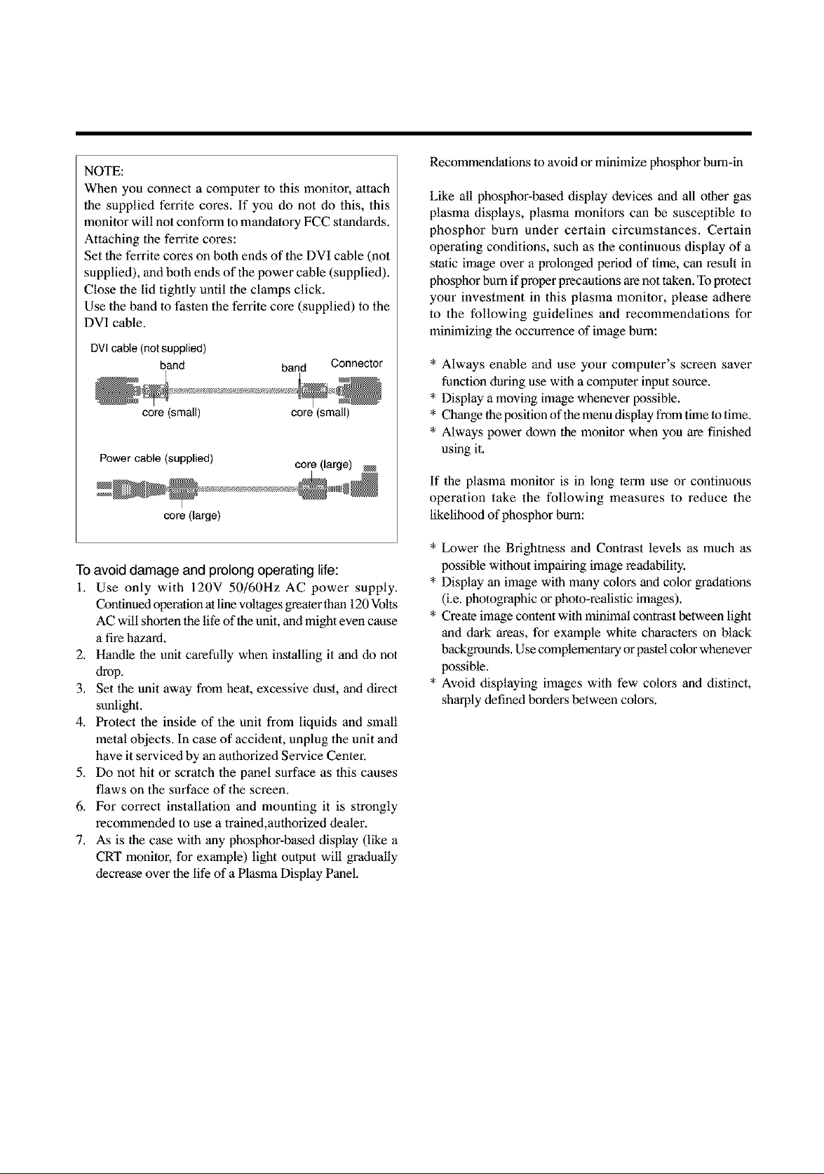
NOTE:
When you connect a computer to this monitor, attach
the supplied ferrite cores. If you do not do this, this
monitor will not conform to mandatory FCC standards.
Attaching the ferrite cores:
Set the ferrite cores on both ends of the DVI cable (not
supplied), and both ends of the power cable (supplied).
Close the lid tightly until the clamps click.
Use the band lo faslen the ferrite core (supplied) to the
DVI cable.
DVI cane (not supplied)
bend bend Connector
core (smell) core (smell)
Power cable (supplied)
core(large)
To avoid damage and prolong operating life:
i. Use only with 120V 50/60Hz AC power supply.
ContianeA operation at linevoltages greater than 120 Volts
AC will shorten thelife of the unit, and might even cause
a fire hazard.
2. Handle the unit carefully when installing it and do not
drop.
3. Set the unit away from heal, excessive dust, and direct
sunlight.
4. Protect the inside of the unit from liquids and small
metal objects. In case of accident, unplug the unit and
have it serviced by an authorized Service Center.
5. Do not hit or scratch the panel surface as this causes
flaws on the surface of the screen.
6. For correct installation and mounting it is strongly
recommended to use a traiand,authorized dealer.
7. As is the case with any phosphor-based display (like a
CRT monitor, for example) light output will gradually
decrease over the life of a Plasma Display Panel.
Recommendations to avoid or minimize phosphor bum-in
Like all phosphor-based display devices and all other gas
plasma displays, plasma monitors can be susceptible to
phosphor burn under certain circumstances. Certain
operating conditions, such as the continuous display of a
static image over a prolonged period of time, can result in
phosphor bum if proper precautions are not taken. To protect
your investment in this plasma monitor, please adhere
to the following guidelines and recommendations for
minimizing the occurrence of image bum:
* Always enable and use your computer's screen saver
function during use with a computer input source.
* Display a moving image whenever possible.
* Change the position of the menu display from time to time.
* Always power clown the monitor when you are finished
using it.
If the plasma monitor is in long term use or continuous
operation take the following measures to reduce the
likelihood of phosphor bum:
* Lower the Brightness and Contrast levels as much as
possible without impairing image readability.
* Display an image with many colors and color gradations
(i.e. photographic or photo-realistic images).
* Create image content with minimal contrast between light
and dark areas, for example white characters on black
backgrounds. Use complementary or pastel color whenever
possible.
* Avoid displaying images with few colors and distinct,
sharply defined borders between colors.
Contents
How to Attach Options to the Plasma Monitor .... I
Introduction ..................................................... 2
Introdudionto the
PlasmaMonitor........................................................ 2
Thefeaturesyou'llenjoyinclude:............................... 2
ContentsofthePackoge........................................... 2
Options .................................................................. 2
Part Names und Function .................................. 3
Front View ............................................................... 3
RearView / Terminal Board ...................................... 4
RemoteControl ........................................................ 5
Baltery Installation and Replacement ........................... 6
Using the wired remote control mode .......................... 7
Operating Range .......................................................... 7
Handling the remote conffoJ ......................................... 7
Installation ...................................................... $
ConnectingYourPCor MacintoshComputer............... 9
ConnectionswithEquipmentthathasa DigitalInterface... 9
ConnectingYourDocumentCamera........................... 9
ConnectingYourVCRor LaserDiscPlayer.................. 9
ConnedingYourDVDPlayer..................................... 9
ExternalSpeakerConnections.................................. 10
PinAssignmentsand SignalLevels
for 15pin RGB(Analog)......................................... 11
PinConfigurationandSignal
oftheRGB3 INConnector(DVIConnector).............. 11
BasicOperations ............................................. 12
POWER ................................................................ 12
"Ibturn the unit ON and OR: .................................... 12
VOLUME .............................................................. 12
"Ibadjustthe vcClume:................................................ 12
MUTE ................................................................... 12
"]b canceJ the sound: .................................................. 12
DISPLAY................................................................ 12
"lbcheck the settings: ................................................. 12
DIGITALZOOM ..................................................... 12
AUTO ADJUST ...................................................... 12
"lbadjust the size or quality of the picture
automatically: ............................................................ 12
OFF TIMER........................................................... 13
"lbset the offtimer: ................................................... 13
"lbcheck the remaining time: ..................................... 13
"lbcancel the off timer ............................................... 13
OSMControls................................................. 18
Menu Operations ................................................... 18
Pidure SettingsMenu ............................................. 20
Adjusting the picture ................................................. 20
Selting the picture mode according to the
brightness of the room ............................................... 21
Setting the color temperature .................................... 22
Adjusting the cdor m the desired quality ................... 23
Reducing noise inthe picture ..................................... 24
Sound Settings Menu .............................................. 25
Adjusting the treble, bass and left/right balance ........ 25
Screen Settings Menu ............................................. 26
Adjusting the Position, Size, Fine Picture,
Picture Adj ................................................................ 26
Function Settings Menu .......................................... 27
Seuing the on-screen menu ....................................... 27
Adjusting the position of the menu display ................ 28
Setting the power management for computer images ..... 29
POWER/STANDBY indicator ................................... 30
Setting the gray level for the sides of fhe screen ......... 31
Setting the picture to suit the movie ........................... 31
Selting RGB3 ADJ ..................................................... 32
Reducing bum-in of the screen .................................. 32
Setting the time for "INVERSE". ............................... 33
Seuing the time for "SCREEN WIPER". ................... 34
Reseldng to the default values .................................... 35
Options Settings Menu ............................................ 36
Setting the allocation of the audio connectors ........... 36
Setting the BNC connectors ...................................... 36
Seuing a computer image to the correct RGB
select screen ............................................................. 37
Selting high definition images to (he suitable
screen size ............................................................... 38
Setting the picture size for RGB input signals ............ 38
Information Menu ................................................. 39
Checking the frequencies, polarities of input signals,
and resolution ........................................................... 39
Setting the language for the menus ............................. 39
Setting the video signal fo_Tnat.................................. 40
External Control ............................................. 41
Table of Signals Supported .............................. 55
Supportedresolution.............................................. 55
Troubleshooting ............................................. 57
Specifications ................................................. 58
WIDEOperutions............................................. 14
Watching with o wide screen (manuo[) .................... 14
When watching videos or digital video discs ............. 14
When watching high definition video source ............. 14
Watching computer images with o wide screen ......... 15
When "PICTURE SIZE" is set to "OFF". .................. 15
MULTISCREENOperutlons ............................... 16
Showing a couple of pidures on the screen
at the some time ................................................... 16
Operations in the Side-by-side mode .......................... 16
Operations in the Picture-in-picture mode .................. 17
Selecting the input signals m be displayed ................. 17
Adjusting (he OSM conlrols ...................................... 17
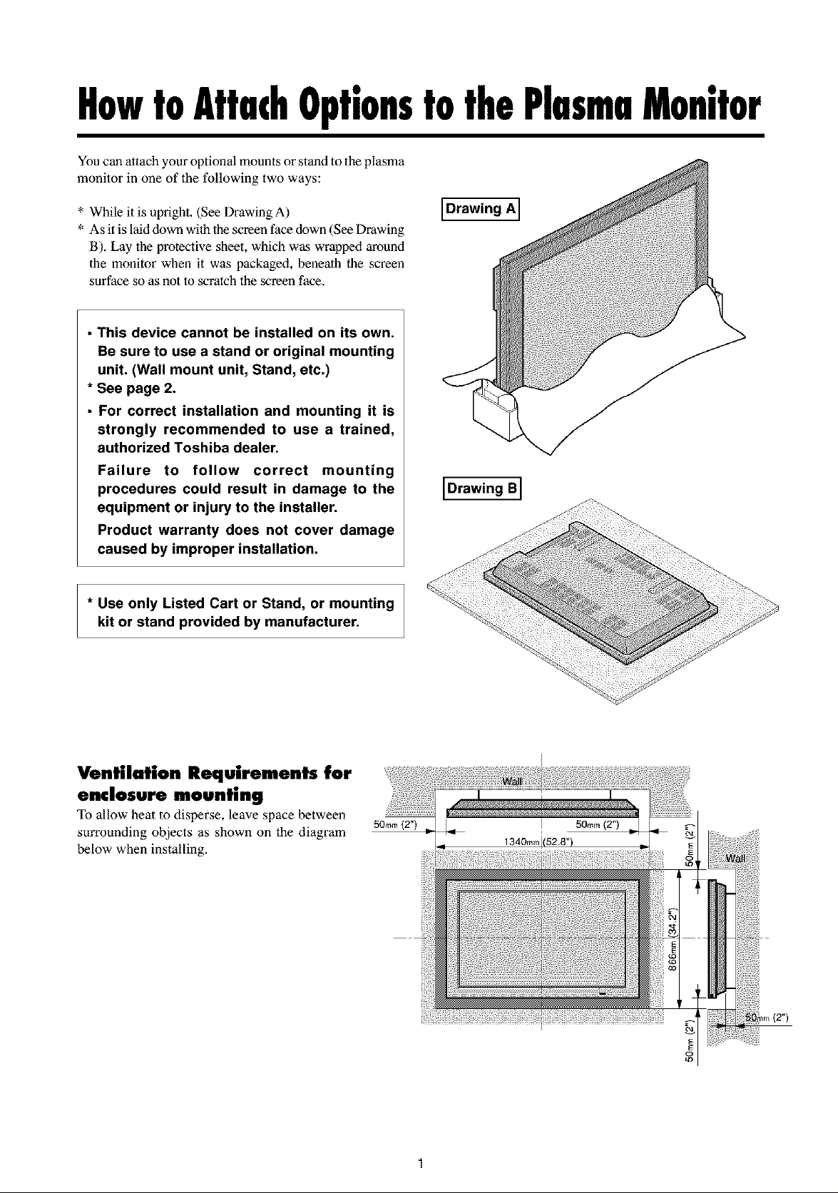
HowtoAttachOptionstothePlasmaMonitor
You can attach your optional mounts or stand to the plasma
monitor in one of the following two ways:
* While it is upright. (See Drawing A)
* As it is laid down with the screen face down (See Drawing
B). Lay the protective sheet, which was wrapped around
the monitor when it was packaged, beneath the screen
surface so as not to scratch the screen face.
• This device cannot be installed on its own.
Be sure to use a stand or original mounting
unit. (Wall mount unit, Stand, etc.)
* See page 2.
• For correct installation and mounting it is
strongly recommended to use a trained,
authorized Toshiba dealer.
Failure to follow correct mounting
procedures could result in damage to the
equipment or injury to the installer.
Product warranty does not cover damage
caused by improper installation.
* Use only Listed Cart or Stand, or mounting
kit or stand provided by manufacturer.
Drawing A]
IDrawing BI
Ventilation Requirements for
enclosure mounting
allow heat to disperse,leave spacebetween
surrounding objects as shown on the diagram
below when installing.
50ram (2"1
o
Introduction
Introduction to the Plasma Monitor
Toshiba plasma monior is aseamless Nend of cutting-_ge
visual technology and sophisticated design. At 50-inches,
with a 16:9 aspect ratio, the Plasma monitor certainly
makes a big impression. However, at a mere 4.2 inches/
107 mm thin, the monitor's sleek techno-art lines blend in
well with your environment. Plasma monitor crisp, vivid
image quality will transform data from any graphic
medium from PCs to DVD players- into art. And weighing
only 98 lbs/44.5 kg, it actually can be hung almost
anywhere. Toshiba has made sure that a host of multimedia
resources can be easily connected and displayed as
brilliantly as intended on the plasma monitor.
The features you'll enjoy include:
50-inch screen
16:9 aspect ratio
Capsulated Color Filter (CCF) and black matrix
4.2 inch / 107 mm thin
98 lbs/44.5 kg light
High-resolution screen: 1365 × 768 pixels
160-degrees of off-axis viewing, horizontally and
vertically.
• Flicker - and warp - free display provides excellent
image geometry even in screen comers
• Not affected by magnetic fields, no color drift or edge
distortion.
• VGA, SVGA, XGA, SXGA, UXGA computer signal
compatibility
• NTSC, PAL, SECAM, composite and S-Video signal
compatibility
• 480P, 10801, 720P and HDTV signal compatibility
• PCs, VCRs, Laser Disc and DVD player source
compatibility
• AccuBlend TM scan conversion automatically converts
VGA, SVGA, XGA, SXGA and UXGA signals to the
panel's native resolution
• Advanced Mass Area Sampling Progressive Scan
method is employed.
• RGB input (3*), Video input (3), DVD/HD input (2*),
Audio input (3), External Control input (1)
• AccuColor control system provides user selectable on-
screen color temperature settings
• New Drive Technology
• Component video input terminal for DVD, 15.75kHz
(Y, CB, Cn )
• Digital broadcasting source compatibitly
• Seven languages (English, German, French, Italian,
Spanish, Swedish, and Japanese)
* You can select RGB source or Component source for
the 5BNC terminal. When selecting an RGB input, the
source is switched to the RGB input (3); when selecting
a component input, the source is switched to the DVD/
HD input (2).
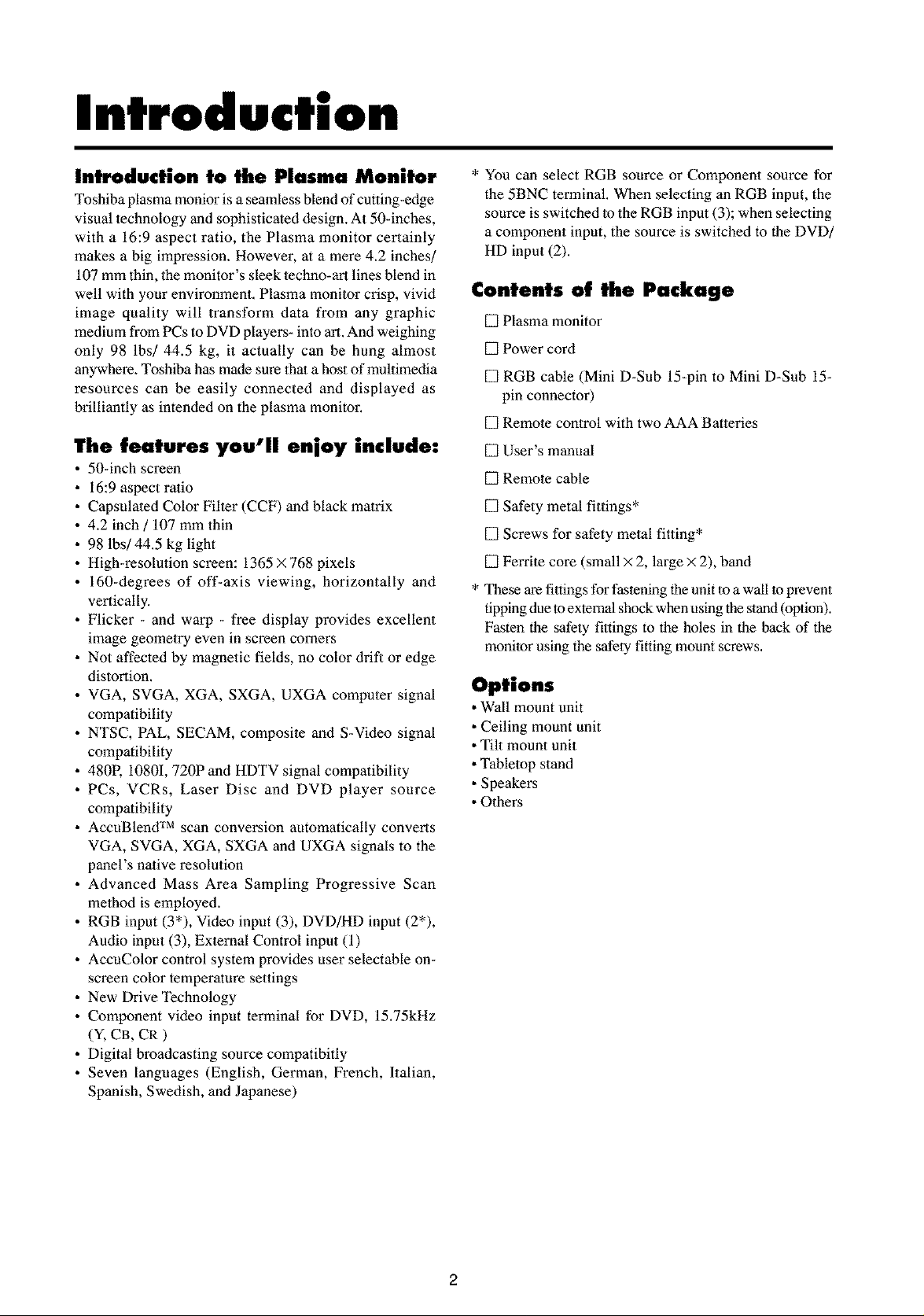
Contents of the Package
[] Plasma monitor
[] Power cord
[] RGB cable (Mini D-Sub 15-pin to Mini D-Sub 15-
pin connector)
[] Remote control with two AAA Batteries
[] User's manual
[] Remote cable
[] Safety metal fittings*
[] Screws for safety metal fitting*
[] Ferrite core (small × 2, large × 2), band
* These are fittings for fastening the unit to a wall to prevent
tipping due to external shock when using the stand (option).
Fasten the safety fittings to the holes in the back of the
monitor using the safety fitting mount screws.
Options
• Wall mount unit
• Ceiling mount unit
• Tilt mount unit
• Tabletop stand
• Speakers
• Others
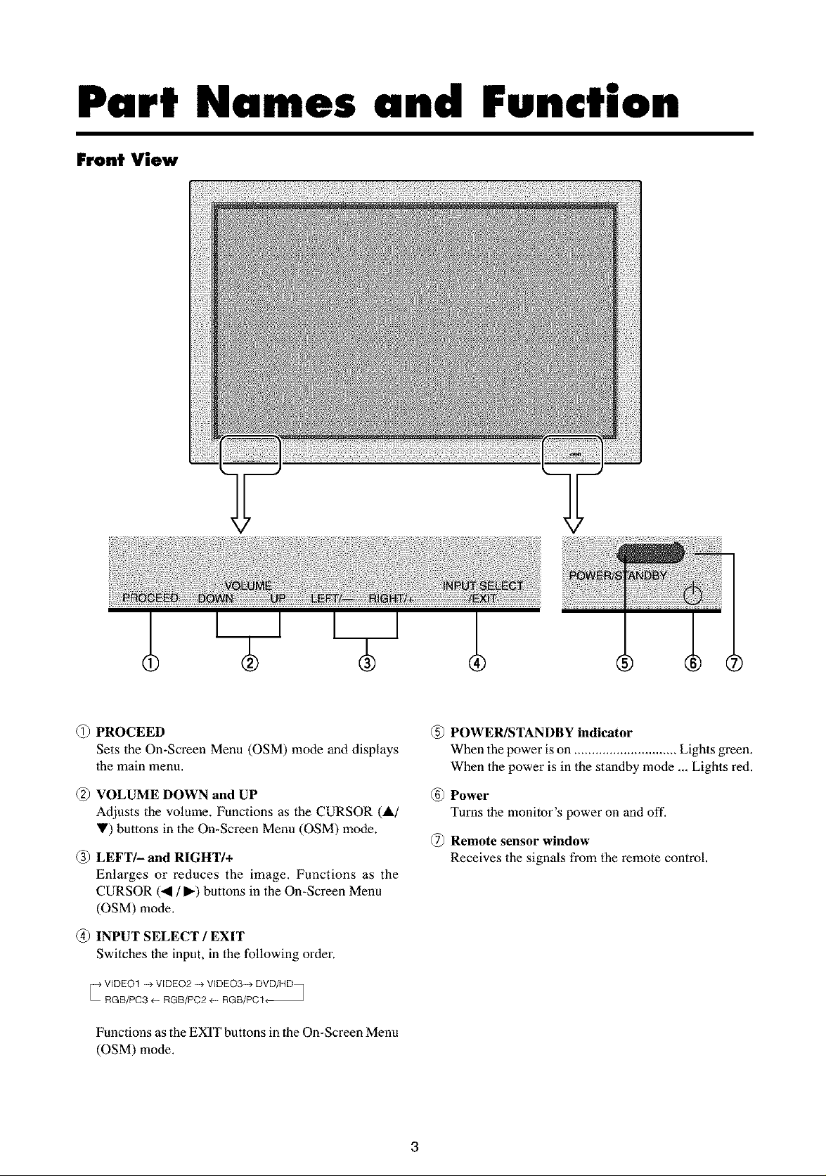
Part Names and Function
Front View
(_) PROCEED
Sets the On-Screen Menu (OSM) mode and displays
1he main menu,
VOLUME DOWN and UP
Adjusts the volume. Functions as the CURSOR (&/
V) buttons in the On-Screen Menu (OSM) mode.
(_) LEFT/- and RIGHT/+
Enlarges or reduces the image. Functions as the
CURSOR (..4 / _) buttons in the On-Screen Menu
(OSM) mode.
(_) INPUT SELECT / EXIT
Switches the input, in the following order.
_ VIDEO1 _>VIDEO2 _> VIDEO3_> DVD/HD_
RGB/PC3 _ RGB/PC2 _ RGB/PCI_
Functions as the EXIT buttons in the On-Screen Menu
(OSM) mode.
(_) POWER/STANDBY indicator
When the power is on ............................. Lights green.
When the power is in the standby mode ... Lights red.
Power
Turns the monitor's power on and off.
Remote sensor window
Receives the signals from the remote control.
3
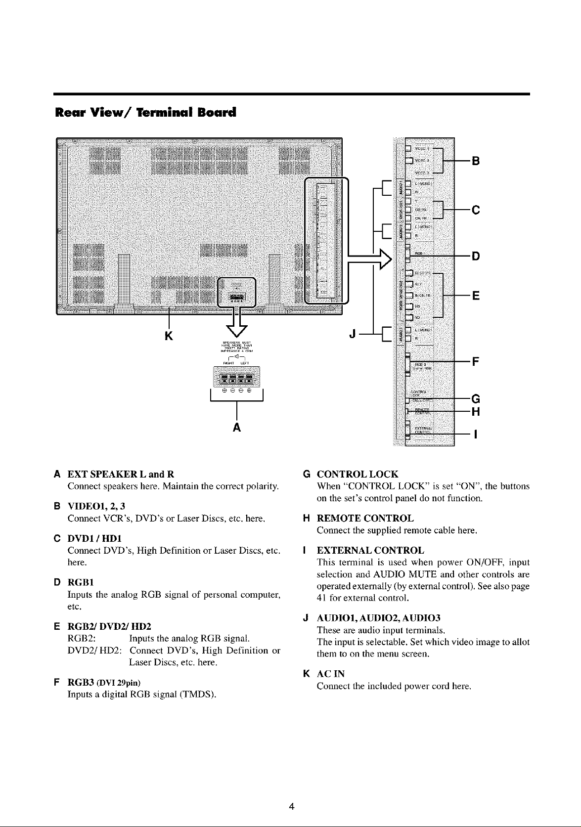
Rear View/Terminal Board
K
A
A EXT SPEAKER L and R
Connect speakers here. Maintain the correct polarity.
B VIDEOI, 2, 3
Connect VCR's, DVD's or Laser Discs, etc. here,
C DVDI / HDI
Connect DVD's, High Definition or Laser Discs, etc.
here,
D RGBI
Inputs the analog RGB signal of personal computer,
etc.
I= RGB2/DVD2/HD2
RGB2: Inputs the analog RGB signal.
DVD2/HD2: Connect DVD's, High Definition or
Laser Discs, etc. here.
F RGB3 (DV! 29pin)
Inputs a digital RGB signal (TMDS).
d
F
G
G
CONTROL LOCK
When "CONTROL LOCK" is set "ON", the buttons
on 1he set's control panel do not function.
H
REMOTE CONTROL
Connect the supplied remote cable here,
I
EXTERNAL CONTROL
This terminal is used when power ON/OFF, input
selection and AUDIO MUTE and other controls are
operated externally (by external control), See also page
41 for external control,
d
AUDIO1, AUDIO2, AUDIO3
These are audio input terminals,
The input is selectahle. Set which video image to allot
them lo on the menu screen.
K
AC IN
Connect the included power cord here.
4
Remote Control
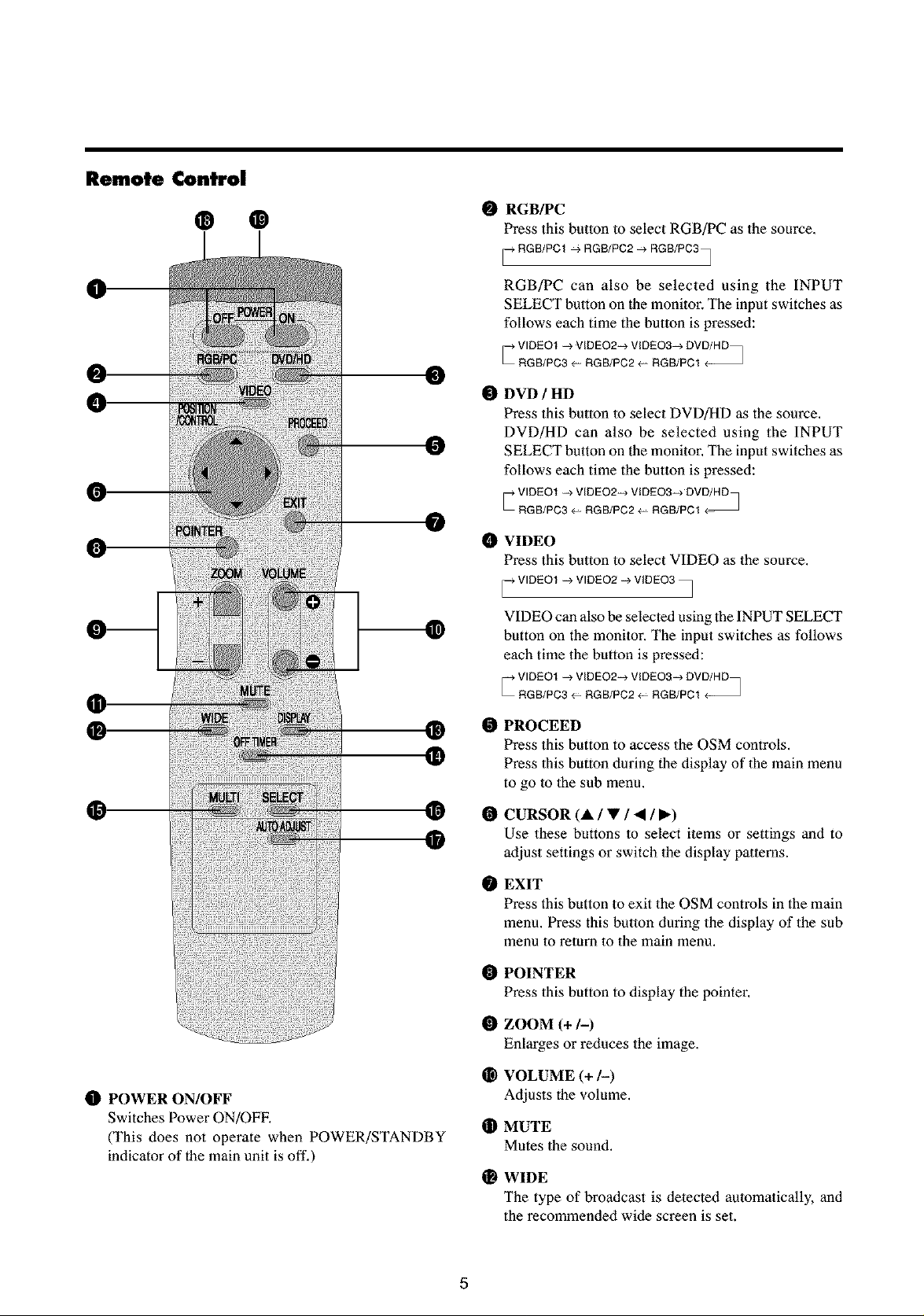
@ ®
0
0
0
0
O RGB/PC
Press this button to select RGB/PC as the source.
RGB/PCI ,, RGB/PC2-_ RGB/PC3_
7
RGB/PC can also be selected using the INPUT
SELECT button on the monitor. The input switches as
follows each time the button is pressed:
_ VIDEO1 _> VIDEO2_ VIDEO3_4, DVD/HD_
RGB/PC3 _ RGB/PC2 _- RGB/PC1
O DVD / HD
Press this button lo select DVD/HD as the source.
DVD/HD can also be selected using the INPUT
SELECT button on the monitor. The input switches as
follows each time the button is pressed:
_ VIDEO1 _> VIDEO2_ VlDEQ3-_ DVD/HD_
RGB/PC3 4- RGB/PC2 _- RGB/PC1
O VIDEO
Press this button to select VIDEO as the source.
i_ VIDEO1 --> VIDEO2 --> VIDEO3 •
VIDEO can also be selected using the INPUT SELECT
button on the monitor. The input switches as follows
each time the button is pressed:
/
I_ POWER ON/OFF
Switches Power ON/OFF,
(This does not operate when POWER/STANDBY
indicator of the main unit is off,)
®
@
_ VIDEO1 _> VlDEO2-_ VlDEO3_ DVD/HD_
RGB/PC3 4- RGB/PC2 _- RGB/PC1
O
PROCEED
Press this button to access the OSM controls.
Press 1his button during the display of 1he main menu
to go lo 1he sub menu.
O
CURSOR (A / • / • / I_)
Use these buttons to select items or settings and to
adjust settings or switch the display patterns.
EXIT
Press this button to exit the OSM controls in the main
menu. Press this button during the display of the sub
menu to return to the main menu.
O
POINTER
Press this button to display the pointer.
O
ZOOM (+ 1-)
EnLarges or reduces the image.
O
VOLUME (+/-)
Adjusts the volume.
®
MUTE
Mutes the sound.
WIDE
The type of broadcast is detected automatically, and
the recommended wide screen is set.
5
O DISPLAY
Displays the source settings on the screen.
OFF TIMER
Activates the off timer for the unit.
MULTI
Press this button to select a screen mode from among
single mode, side by side, and picture in picture.
SELECT
Press this button to select the active piclare in a multi
screen mode.
AUTO ADJUST
Press this button to adjust Fine Picture, Picture ADJ,
Position, and Contrast automatically, or to switch the
screen size to ZOOM mode automatically with the
superimposed caption displayed ffdly only when the
picture contains dark areas above and below the picture.
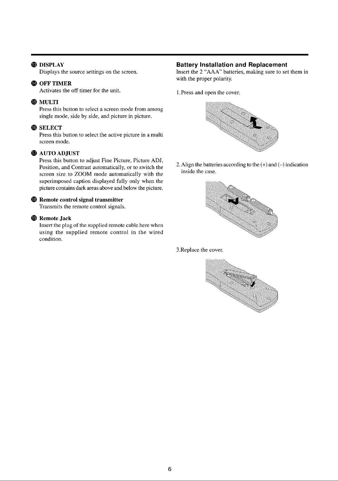
Battery Installation and Replacement
Insert the 2 "AAA" batteries, making sure to set them in
with the proper polarity.
1.Press and open the cover.
2. ALignthe batteries according to the (+) and (-) indication
inside the case.
Remote control signal transmitter
Transmits the remote control signals,
Remote Jack
Insert the plug of the supplied remote cable here when
using the supplied remote control in the wired
condition,
iiiiiiiiiiiiiiiiii!i!iiiii!!ii!iiii!i!ii!i!iiiili!iii!!iiii
3.Replacethecover.
6
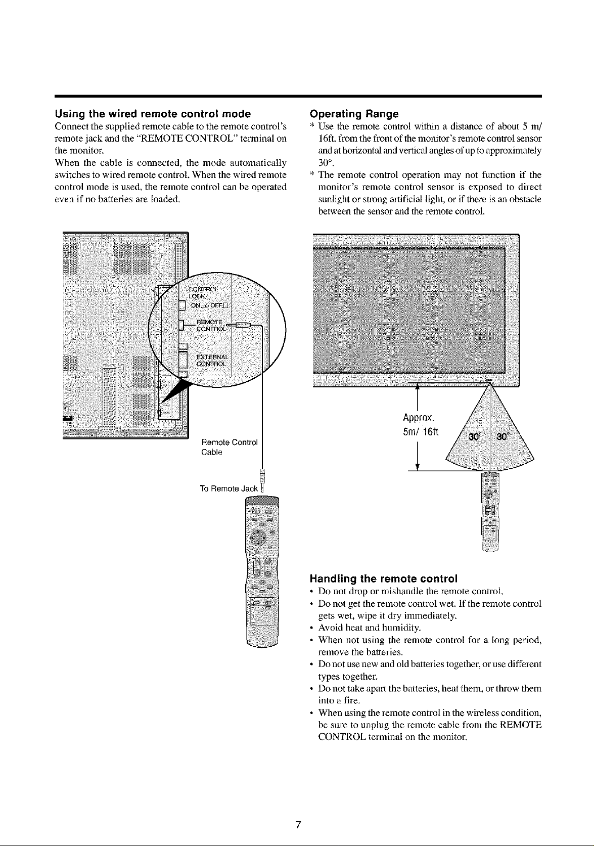
Using the wired remote control mode
Connect the supplied remote cable to the remote control's
remote jack and the "REMOTE CONTROL" terminal on
the monitor.
When the cable is connected, the mode automatically
switches to wired remote control. When the wired remote
control mode is used, the remote control can be operated
even if no batteries are loaded.
Operating Range
* Use the remote control within a distance of about 5 m]
16ft.from the front of the monitor's remote control sensor
antiathorizontal and vertical angles of up to approximately
30°.
* The remote control operation may not function if the
monitor's remote control sensor is exposed to direct
sunlight or strong artificial light, or if there is an obstacle
between the sensor and the remote control.
Remote Control
Cable
To Remote Jack
Approx.
5rn/16ft
Handling the remote control
• Do not drop or mishandle the remote control.
• Do not get the remote control wet. If the remote control
gets wet, wipe it dry immediately.
• Avoid heat and humidity.
• When not using the remote control for a long period,
remove the batteries.
• Do not use new and old batteries together, or use different
types together.
• Do not take apart the batteries, heat them, or throw them
into a fire.
• When using the remote control in the wireless condition,
be sure to unplug the remote cable from the REMOTE
CONTROL terminal on the monitor.
7
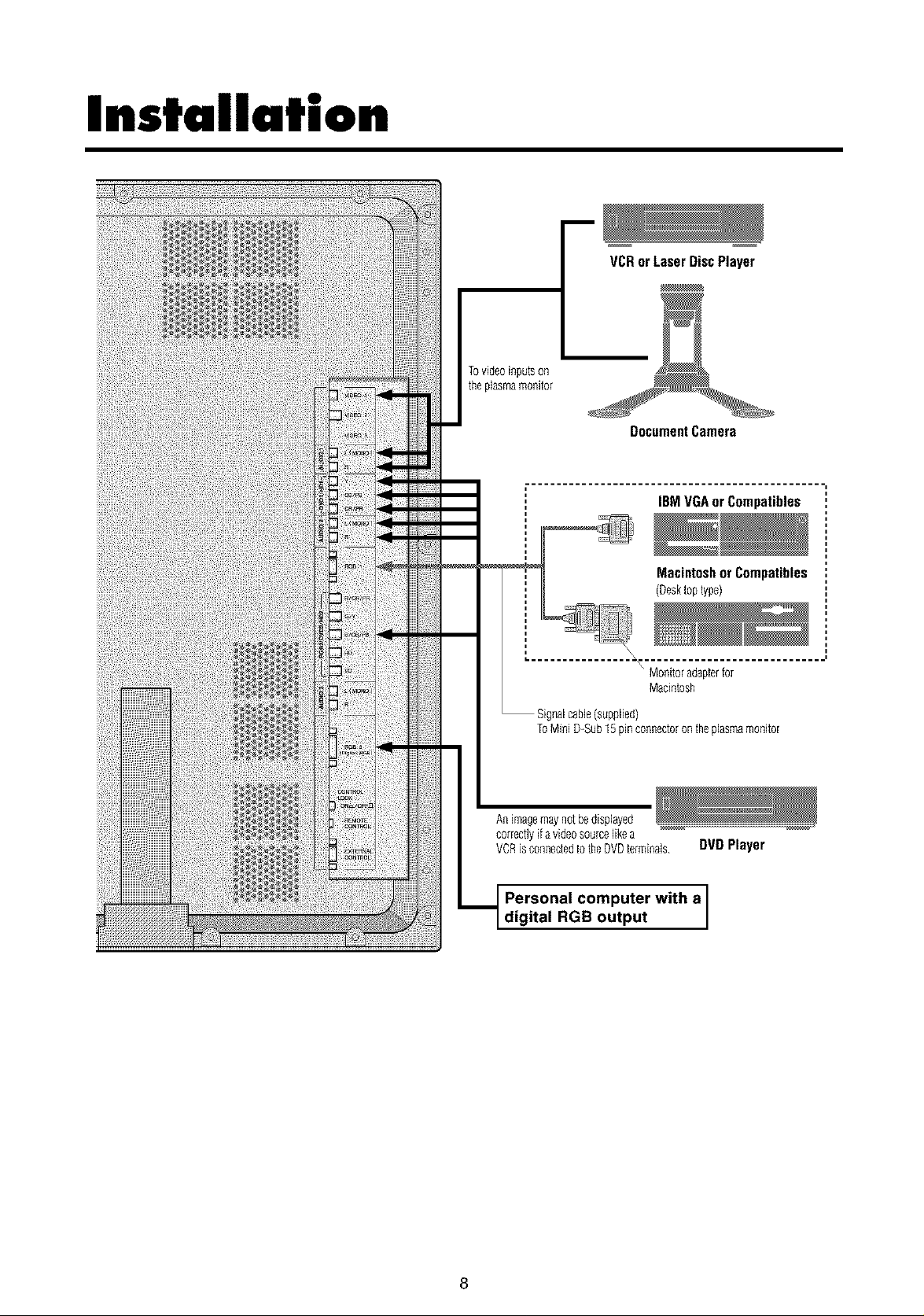
Installation
VCRorLaser DiscPlayer
Tovideoinputson
theplasmamonitor
DocumentCamera
IBMVGAorCompatibles
Macintoshor Compatibles
(Desktoptype)
Monitoradapterfor
Macintosh
halcable(supplied)
ToMiniD-Sub15pinconnectorontheplasmamonitor
Animagemaynotbe displayed
correctlyifavideosourcelikea
VCRisconnectedto theDVDterminals DVDPlayer
Personal computer with a
digital RGB output
8
ConnectingYour PCor Macintosh Computer
Connecting your PC or Macintosh computer m your plasma
monitor will enable you to di_lay your computer's sc_en
image for an impressive presentation. The plasma monitor
supports the signals described on page 55.
To connect a PC, Macintosh or compatible graphics adapter,
simply:
i. Turn off the power to your plasma monitor and computer.
2. If your PC does not support SXGA/XGA/SVGA/VGA
you will need to install an SXGA/XGA/SVGA/VGA
graphics board. Consult your computer's owner's manual
for your SXGA/XGA/SVGA/VGA configuration. If you
need to install a new board, see the manual that comes
with your new graphics board for installation instructions.
3. The plasma monitor provides signal compatibility up to
VESA 1600× 1200 (UXGA). However, it is not
recommended to use this resolution due to image
readability on the monitors 1365 × 768 native pixel
resolution panel.
4. Use the signal cable that's supplied to connect your PC or
Macintosh computer to the plasma monitor. For Macintosh,
use the monitor adapter lo connect lo your computer's
video port.
5. Turn on the plasma monitor and the computer.
6. If the plasma monitor goes blank after a peri_l of inactivity,
it may be caused by a screen saver installed on the computer
you've connected lo the plasma monitor.
When using a Macintosh with the plasma monitor, the
following four display standards are supported using the
Macintosh adapter :
13" fixed mode
16" fixed mode
19" fixed mode
21" fixed mode
The 19" fixed mode is recommended for the plasma monitor.
Connecting Your Document Camera
You can connect your plasma monitor to a document
camera. To do so, simply:
i. Turn off the power to your plasma monitor and
document camera.
2. Use a standard video cable to connect your document
camera to the Video input on your plasma monitor.
3. Turn on the plasma monitor and the document camera.
Connecting Your VCR or Laser Disc
Player
Use common RCA cables (not provided) to connect your
VCR or laser disc player lo your plasma monitor. To make
these connections, simply:
i.
Turn off the power to your plasma monitor and VCR
or laser disc player.
2.
Connect one end of your RCA cable to the video output
connector on the back of your VCR or laser disc player,
connect the other end to the Video input on your plasma
monitor. Use standard RCA audio patch cords to
connect the audio from your VCR or laser disc player
to your plasma monitor (if your VCR or laser disc player
has this capability). Be careful to keep your right and
left channel connections correct for stereo sound.
3.
Turn on the plasma monitor and the VCR or laser disc
player.
Connections with Equipment that
has a Digital Interface
Connections can be made with equipment that is equipped
with a digital interface compliant with the DVI (Digital
Visual Interface) standard.
* Use a DVI 29_pin signal cable and the _rrite cores
(supplied) when making connections to theRGB3 IN _VI)
connector of the main unit.
Note that the RGB3 IN(DVI) terminal does not support
analog RGB input source.
Connecting Your DVD Player
You can connect your plasma monitor to a DVD player.
To do so, simply:
i. Turn off the power to your plasma monitor and DVD
player.
2. Use a standard video cable to connect your DVD player
to the Y, Cb, and Cr inputs on your plasma monitor.
Or use the DVD-player's S-Video output. Use a
standard S-Video cable to connect to the S-Video input
on the plasma monitor.
3. Turn on the plasma monitor and the DVD player.
9
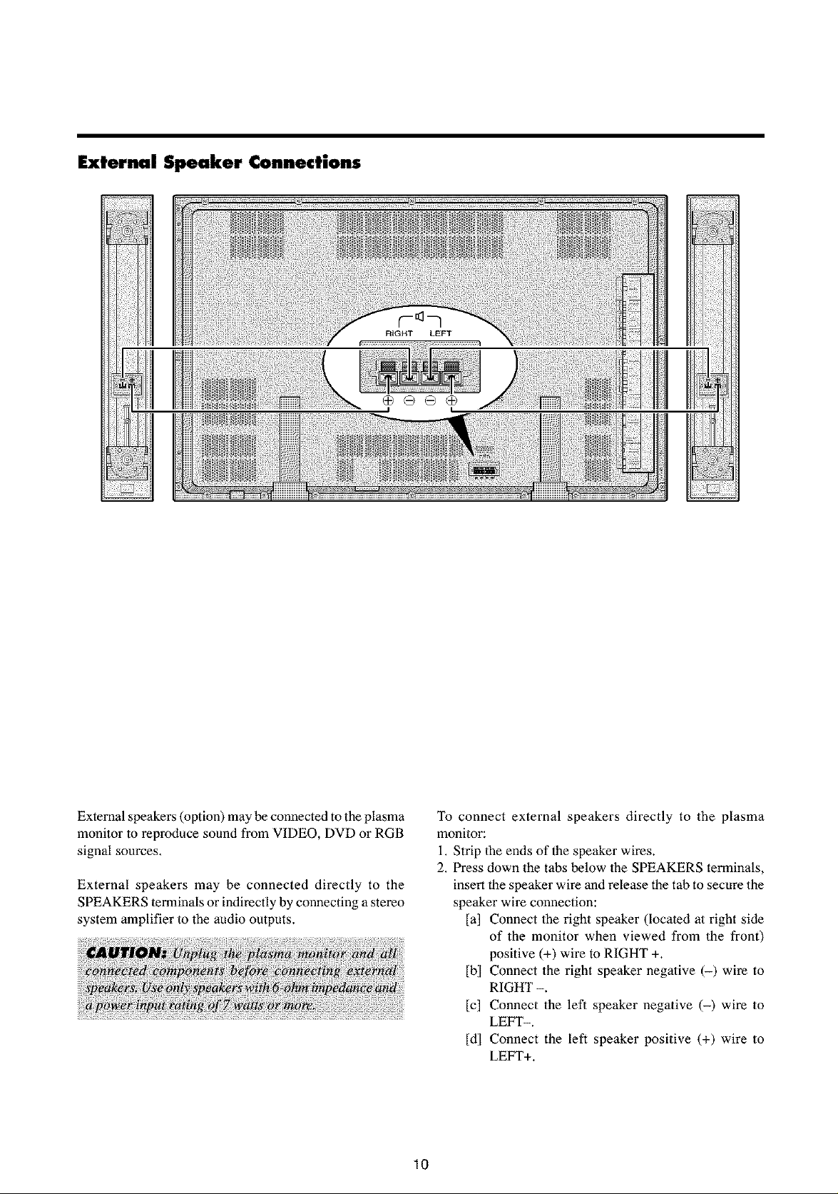
External Speaker Connections
External speakers (option) may be connected to the plasma
monitor to reproduce sound from VIDEO, DVD or RGB
signal sources,
External speakers may be connected directly to the
SPEAKERS terminals or indirectly by connecting a stereo
system amplifier to the audio outputs.
To connect external speakers directly to the plasma
monitor:
i. Strip the ends of the speaker wires.
2. Press down the tabs below the SPEAKERS terminals,
insert the speaker wire and release the tab to secure the
speaker wire connection:
[a] Connect the right speaker (located at right side
of the monitor when viewed from the front)
positive (+) wire to RIGHT +.
[b] Connect the right speaker negative (-) wire to
RIGHT -.
[c] Connect the left speaker negative (-) wire to
LEFT-.
[d] Connect the left speaker positive (+) wire to
LEFT+.
10
Pin Assignments and Signal Levels for 1 5 pin RGB (Analog)
1 Red
3 Blue
5 Ground
7 Green ground
9 No connection
11 No connection
_i_i_!_! _ATA
13 Horizontal sync or Composite sync
VeN_A! _
15 Data clock
Pin Configuration and Signal of the RGB 3 IN Connector (DVI Connector)
The unit is equipped with a type of connector commonly
used for both analog and digital.
(Functionally, this cannot be used for an
analog input.)
(TMDS can be used for one link only.)
RGB 3
uunuuuuu mnm_
Dmmmmmmm _
mmmmmmmmm_
1 T.M.D,S Data 2-
T.M ata
3 TM.D.S Data 2 Shield
:N__ct
5 No connection
7 DDC Data
!iN#ii_i_ _ ii!ii_iiil!ii_iiil!ii_iiil!ii_iiil!ii_iiil!ii_iiil!ii_iiil!ii_iiil!ii_iiil!ii_iii
9 TM.D.S Data 1 -
M_!D:ii_iilD_iii_!!!_iii !!iii_!!!iii_!!!iii_!!!iii_!!!iii_!!!iii_!!!iii_!!!iii_!!!
11 TM.D.S Data 1 Shield
13 No connection
15 Ground
17 TM.D.S Data 0 -
19 T.M.D.S Data OShield
21 No connection
23 TM.D.S Clock +
25 No connection
27 No connection
29 No connection
11
_i;!i! if!i!l;i!:!!_i:!!_i:!!_i:!!_i:!!_i:!!_i:!!_i:!!_i
Basic Operations
POWER
To turn the unit ON and OFF:
i. Plug the power cord into an active AC power outlet.
2. Press the POWER ON button (on the remote control)
to turn on the unit.
The monitor's POWER/STANDBY indicator will light
up (green) when the unit is on.
3. Press the POWER OFF button (on the remote control
or the unit) to turn off the unit.
The monitor's POWER/STANDB Y indicator turns red
and the standby mode is set (only when turning off the
unit with the remote control).
VOLUME
To adjust the volume:
i. Press and hold the VOLUME (_) button (on the remote
control or the unit) to increase to the desired level.
2. Press and hold the VOLUME _ button (on 1he remote
control or the unit) to decrease to 1he desired level.
MUTE
To cancel the sound:
Press the MUTE button on the remote control to cancel
the sound; press again to restore.
DISPLAY
To check the settings:
i. The screen changes each time the DISPLAY button is
pressed.
2. If the button is not pressed for approximately three
seconds, the menu turns off.
DIGITAL ZOOM
Digital zoom specifies the picture position and enlarges
the picture,
i. Press the POINTER button to display the pointer. ( I_ )
To change the size of the picture:
Press the ZOOM+ button and enlarge the picture.
The pointer will change to resemble a magnifying
glass. ( _ )
A press of the ZOOM- button will reduce the picture
and return it to its original size.
To change the picture position:
Select the position with the AV_I • buttons.
2. Press the POINTER button to delete the pointer.
AUTO ADJUST
To adjust the size or quality of the picture
automatically:
Press the AUTO ADJUST button.
Information
• AUTO ADJUST ON setting
When RGB (still picture) input
is selected ...... Fine Picture, Picture ADJ, Position,
and Contrast will be adjusted
automatically.
When RGB (motion picture),
VIDEO, or Y/Pb/Pr (component) input
is selected ...... The screen size switches to ZOOM
mode automatically with the
superimposed caption displayed fully
only when the picture contains dark
areas above and below the picture.
12
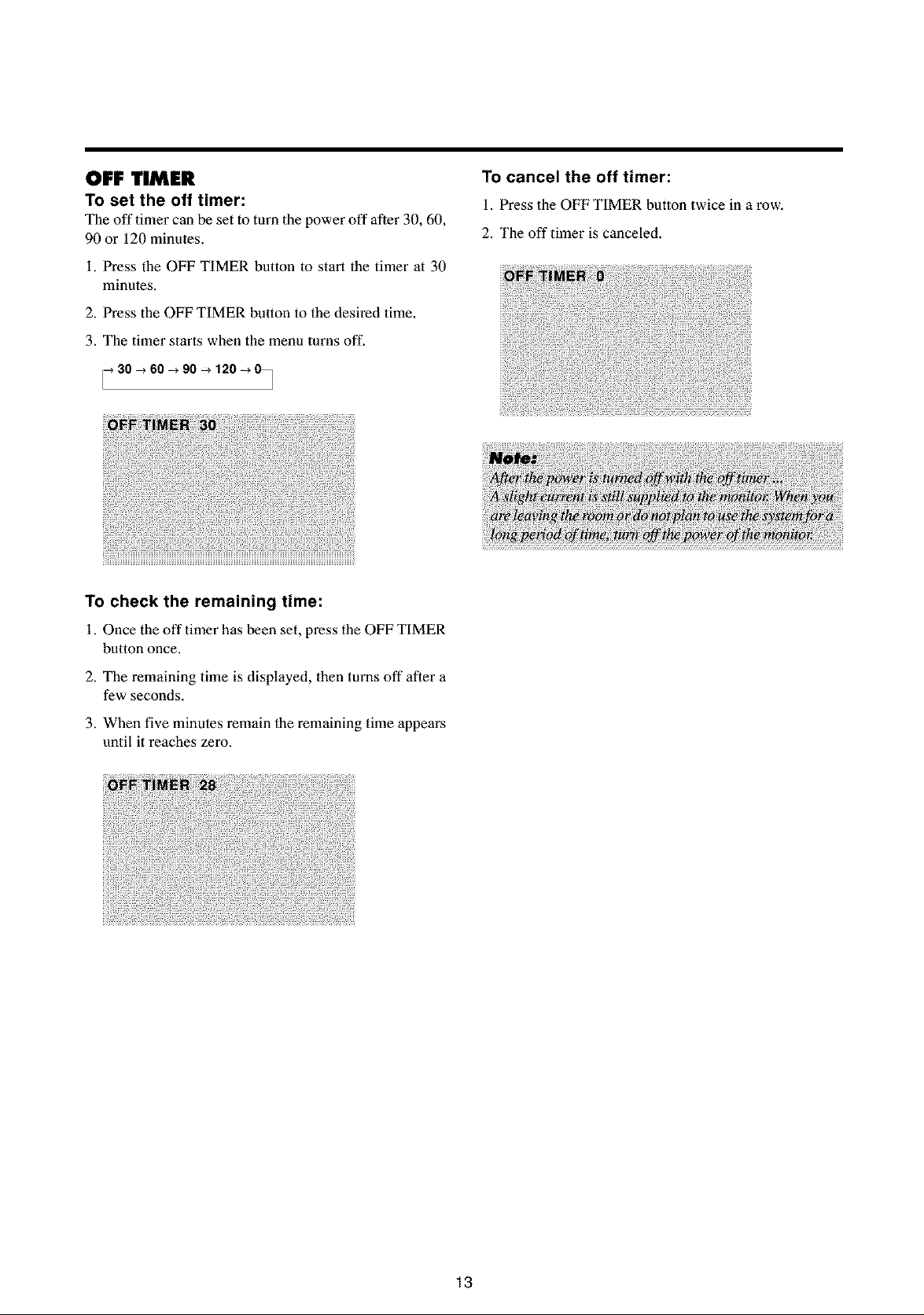
OFF TIMER
To set the off timer:
The off timer can be set to turn the power off after 30, 60,
90 or 120 minutes.
i. Press the OFF TIMER button to start the timer at 30
minutes,
2. Press the OFF TIMER button to the desired time,
3. The timer starts when the menu turns off.
_ 30 _ 60-_ 90-_ 120-_ 0_
To check the remaining time:
i. Once the off timer has been set, press the OFF TIMER
button once.
To cancel the off timer:
i. Press the OFF TIMER button twice in a row.
2. The off timer is canceled.
2. The remaining time is displayed, then turns off after a
few seconds.
3. When five minutes remain the remaining time appears
until it reaches zero.
18
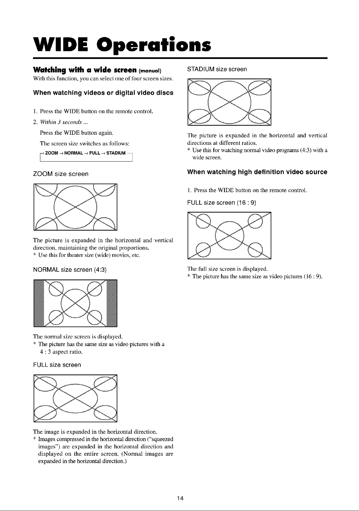
WIDE Operations
Watching with a wide screen (manual)
With this function, you can select one of four screen sizes.
When watching videos or digital video discs
i. Press the WIDE button on the remote control,
2. Within 3 seconds ...
Press the WIDE button again.
The screen size switches as follows:
_-_ZOOM _ NORMAL _ FULL _ STADIUM
/ J
ZOOM size screen
The picture is expanded in the horizontal and vertical
direction, maintaining the original proportions.
* Use this for theater size (wide) movies, etc.
STADIUM size screen
The picture is expanded in the horizontal and vertical
directions at different ratios.
* Use this for watching normal video programs (4:3) with a
wide screen.
When watching high definition video source
i. Press the WIDE button on the remote control.
FULL size screen (16 : 9)
NORMAL size screen (4:3)
The normal size screen is displayed,
* The picture has the same size as video pictures with a
4 : 3 aspect ratio.
FULL size screen
The image is expanded in the horizontal direction.
* Images compressed in the horizontal direction ("squeezed
images") are expanded in the horizontal direction and
displayed on the entire screen. (Normal images are
expanded in the horizontal direction.)
The full size screen is displayed.
* The picture has the same size as video pictures (16 : 9).
14
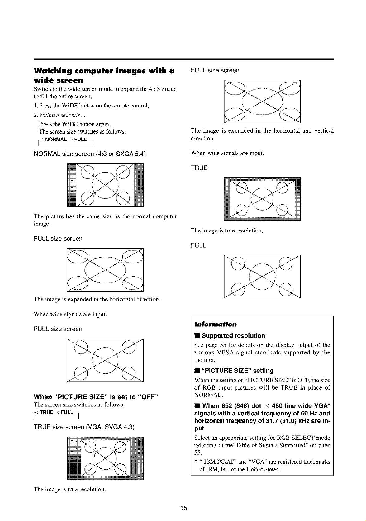
Watching computer images with a
wide screen
Switch to the wide screen mode to expand the 4 : 3 image
to fill the entire screen,
i, Press the WIDE button on the remote control
2, Within 3 seconds ...
Press the WIDE button again.
The screen size switches as follows:
NORMAL -_ FULL •
FULL size screen
The image is expanded in the horizontal and vertical
direction.
NORMAL size screen (4:3 or SXGA 5:4
The picture has the same size as the normal computer
image.
FULL size screen
The image is expanded in the horizontal direction,
When wide signals are input.
FULL size screen
When wide signals are input.
TRUE
The image is true resolution.
FULL
Information
• Supported resolution
See page 55 for details on the display output of the
various VESA signal standards supported by the
monitor.
When "PICTURE SIZE" is set to "OFF"
The screen size switches as follows:
_-_TRUE -_ FULL
/
TRUE size screen (VGA, SVGA 4:3)
The image is 1rue resolution.
• "PICTURE SIZE" setting
When the setting of "PICTURE SIZE" is OFF, the size
of RGB-inpat pictures will be TRUE in place of
NORMAL.
• When 852 (848) dot × 480 line wide VGA*
signals with a vertical frequency of 60 Hz and
horizontal frequency of 31.7 (31.0) kHz are in-
put
Select an appropriate setting for RGB SELECT mode
referring to the"Table of Signals Supported" on page
55.
* " IBM PC/AT" and "VGA" are registered trademarks
of IBM, Inc. of the United States.
15
 Loading...