

TOSHIBA 50H82, 65H82 Service Manual

SERVICE MANUAL
DOCUMENT CREATED IN JAPAN, July, 2004
Color Television
50H82/65H82
FILE NO. 020-200207
(REVISION 1)
N2PSP Chassis
(TAC0263) (TAC0264)

CHAPTER 1 GENERAL ADJUSTMENTS
SAFETY INSTRUCTIONS .............................................................................................................................................. 3
CRT ASSEMBLY REPLACEMENT AND MOUNTING ................................................................................................... 4
PICTURE TUBE COMPONENTS ADJUSTMENT.......................................................................................................... 6
REPLACEMENT OF THE CRT ....................................................................................................................................... 9
SERVICE MODE .......................................................................................................................................................... 10
ELECTRICAL ADJUSTMENT ...................................................................................................................................... 12
GENERAL ADJUSTMENTS
CONVERGENCE ADJUSTMENT ................................................................................................................................ 14
SCREEN AND MIRROR ALIGNMENTS ...................................................................................................................... 17
CIRCUIT CHECKS ....................................................................................................................................................... 18
CHAPTER 2 SPECIFIC INFORMATIONS
SETTING & ADJUSTING DATA .................................................................................................................................... 19
LOCATION OF CONTROLS ......................................................................................................................................... 20
PROGRAMMING CHANNEL MEMORY ....................................................................................................................... 22
MECHANICAL DISASSEMBLY .................................................................................................................................... 23
TABLE OF CONTENTS
SPECIFIC INFORMATIONS
CHASSIS REPLACEMENT PARTS LIST ..................................................................................................................... 27
PC BOARDS BOTTOM VIEW....................................................................................................................................... 47
TERMINAL VIEW OF TRANSISTORS ......................................................................................................................... 59
CIRCUIT BLOCK DIAGRAM ........................................................................................................................................ 61
SPECIFICATIONS .................................................................................................................................................... END
APPENDIX:
CIRCUIT DIAGRAM
– 2 –
CHAPTER 1 GENERAL ADJUSTMENTS
SAFETY INSTRUCTIONS
WARNING: BEFORE SERVICING THIS CHASSIS, READ THE “X-RAY RADIATION PRECAUTION”, “SAFETY PRECAU-
TION” AND “PRODUCT SAFETY NOTICE” INSTRUCTIONS BELOW.
X-RAY RADIATION PRECAUTION
1. Excessive high voltage can produce potentially hazardous
X-RAY RADIATION. To avoid such hazards, the high voltage must not be above the specified limit. The nominal
value of the high voltage of this receiver is (A) kV at zero
beam current (minimum brightness) under a 120V AC
power source. The high voltage must not, under any circumstances, exceed (B) kV.
Refer to table-1 for high voltage (A), (B).
(See SETTING & ADJUSTING DATA on page 19)
Each time a receiver requires servicing, the high voltage
should be checked following the HIGH VOLTAGE CHECK
procedure in this manual. It is recommended that the reading of the high voltage be recorded as a part of the service
record. It is important to use an accurate and reliable high
voltage meter.
SAFETY PRECAUTION
WARNING : Service should not be attempted by anyone unfamiliar with the necessary precautions on this receiver. The following are the necessary precautions to be observed before
servicing this chassis.
1. An isolation Transformer should be connected in the power
line between the receiver and the AC line before any service is performed on the receiver.
2. Always discharge the picture tube anode to the CRT conductive coating before handling the picture tube. The picture tube is highly evacuated and if broken, glass fragments
will be violently expelled. Use shatter proof goggles and
keep picture tube away from the unprotected body while
handling.
3. When replacing a chassis in the cabinet, always be certain that all the protective devices are put back in place,
such as; non-metallic control knobs, insulating covers,
shields, isolation resistor-capacitor network etc.
4. Before returning the set to the customer, always perform
an AC leakage current check on the exposed metallic parts
of the cabinet, such as antennas, terminals, screwheads,
metal overlays, control shafts etc. to be sure the set is safe
to operate without danger of electrical shock. Plug the AC
line cord directly into a 120V AC outlet (do not use a line
isolation transformer during this check). Use an AC voltmeter having 5000 ohms per volt or more sensitivity in the
following manner:
PRODUCT SAFETY NOTICE
2. This receiver is equipped with a Fail Safe (FS) circuit which
prevents the receiver from producing an excessively high
voltage even if the B+ voltage increases abnormally. Each
time the receiver is serviced, the FS circuit must be checked
to determine that the circuit is properly functioning, following the FS CIRCUIT CHECK procedure in this manual.
3. The only source of X-RAY RADIATION in this TV receiver
is the picture tube. For continued X-RAY RADIATION protection, the replacement tube must be exactly the same
type tube as specified in the parts list.
4. Some part in this receiver have special safety-related characteristics for X-RAY RADIATION protection. For continued safety, parts replacement should be undertaken only
after referring to the PRODUCT SAFETY NOTICE below.
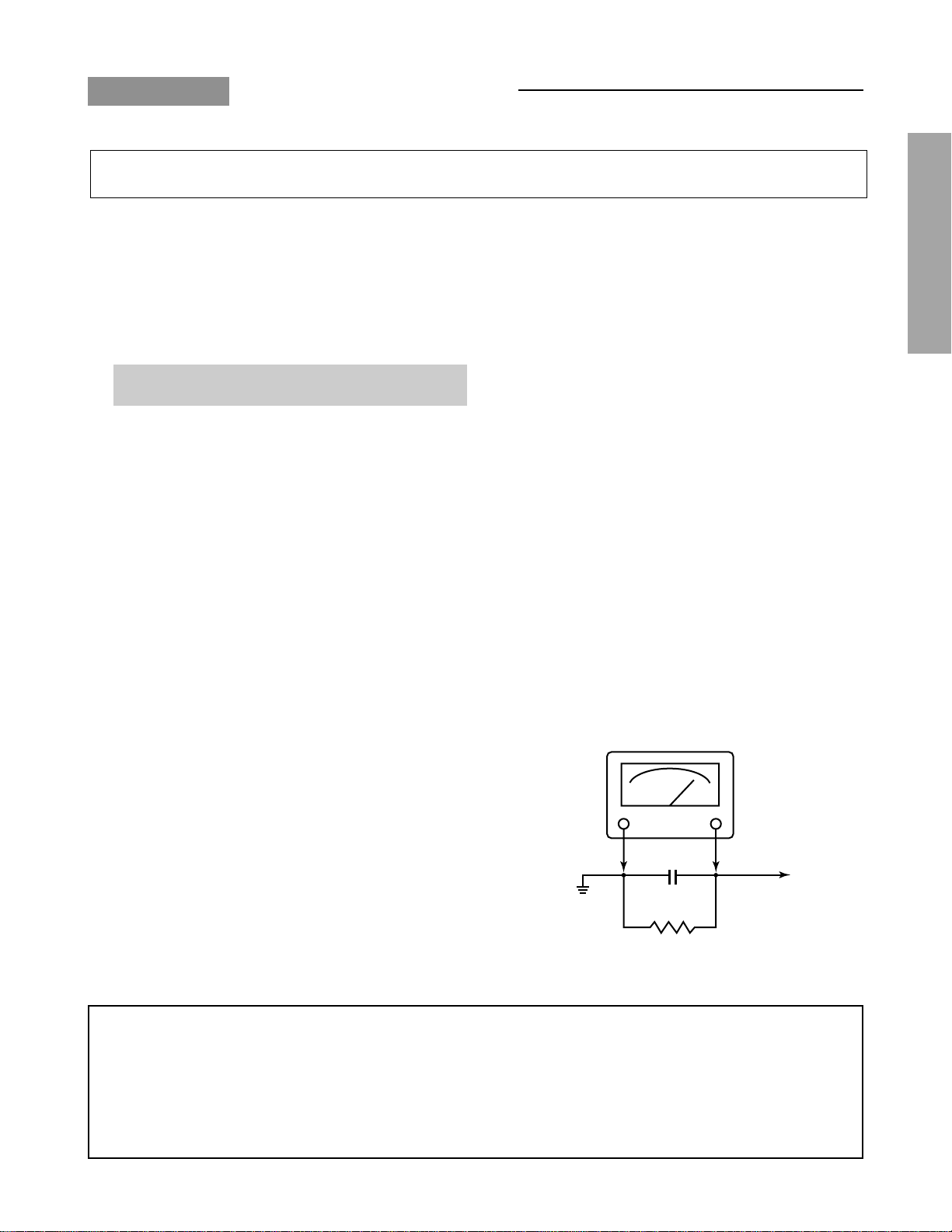
Connect a 1500 ohm 10 watt resistor, paralleled by a 0.15
µF, AC type capacitor, between a known good earth ground
(water pipe, conduit, etc.) and the exposed metallic parts,
one at a time. Measure the AC voltage across the combination of 1500 ohm resistor and 0.15 µF capacitor. Reverse the AC plug at the AC outlet and repeat AC voltage
measurements for each exposed metallic part. Voltage
measured must not exceed 0.3 volts rms. This corresponds
to 0.2 milliamp. AC. Any value exceeding this limit constitutes a potential shock hazard and must be corrected immediately.
AC VOLTMETER
0.15µF
Place this probe on
Good earth ground
such as a water
pipe, conduit, etc.
1500 ohm
10 watt
each exposed
metallic part.
GENERAL ADJUSTMENTS
SPECIFIC INFORMATIONS
Many electrical and mechanical parts in this chassis have special safety-related characteristics. These characteristics are
often passed unnoticed by a visual inspection and the protection afforded by them cannot necessarily be obtained by using
replacement components rated for higher voltage, wattage, etc. Replacement parts which have these special safety characteristics are identified in this manual and its supplements; electrical components having such features are identified by the
international hazard symbols on the schematic diagram and the parts list.
Before replacing any of these components, read the parts list in this manual carefully. The use of substitute replacement
parts which do not have the same safety characteristics as specified in the parts list may create shock, fire, X-ray radiation or other hazards.
– 3 –
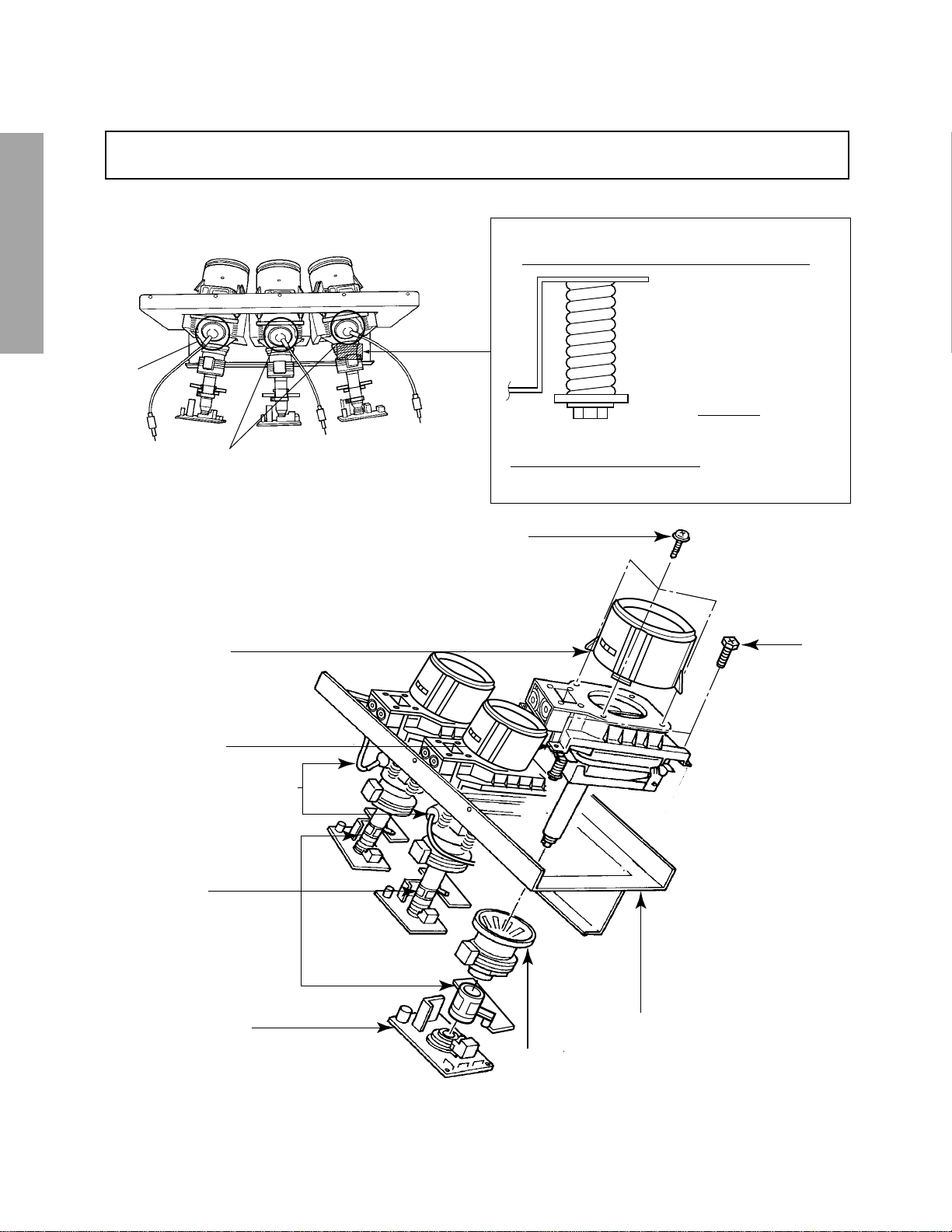
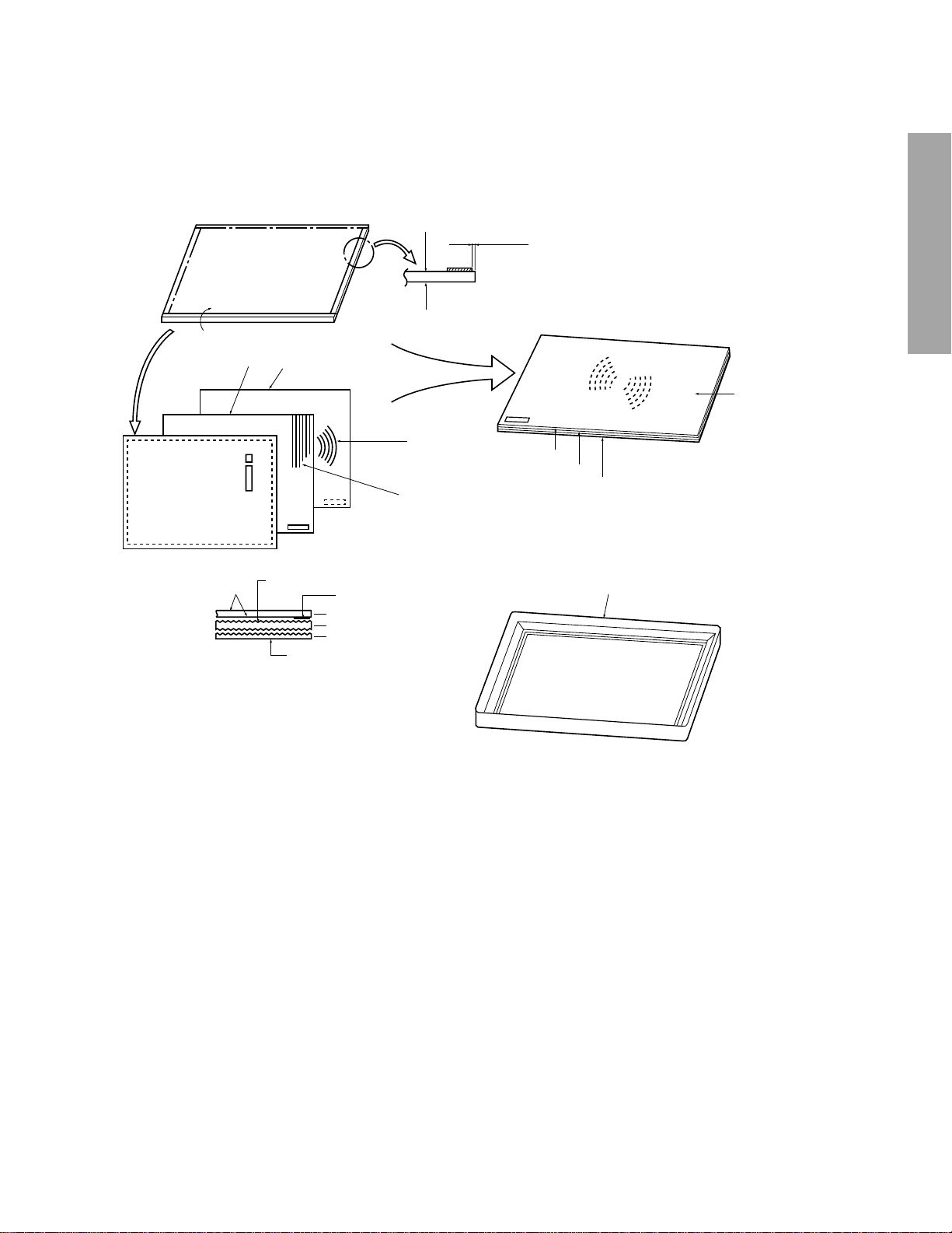
CRT ASSEMBLY REPLACEMENT AND MOUNTING
CAUTION : DO NOT LOOSEN THE HEX HEAD BOLTS WITH SPRINGS (12 PCS), BECAUSE THOSE ARE FOR
SEALING OF CRT COOLANT.
GENERAL ADJUSTMENTS
8 o’clock
4 o’clock
SPECIFIC INFORMATIONS
Lens Assembly
R
GB
Attention Serviceman
The Hex Head
Bolts with
Springs. (see
sketch) used on
CRT assembly,
are “NOT”
Adjustment Screws
DO NOT LOOSEN-FLUID
LEAKAGE WILL OCCUR.
4 Screws
4 Screws
CRT Assembly
CRT Anode Cap Assembly
S.V.M. Coil
CRT DRIVE Board
CRT Mounting
Deflection Yoke and Conver Yoke
Lens and Neck Components View
– 4 –
TO REMOVE CRT (Same procedure for R, G, B)
1. Remove CRT DRIVE Board, S. V. M. COIL and
DEF. YOKE from CRT.
2. Remove Lens Assembly.
3. Detach CRT Anode Cap from CRT.
4. Remove CRT Assembly from CRT Mounting.
CRT REPLACEMENT (Same procedure for R, G, B)
Reverse the removal procedures except the followings.
1. Anode Cable should be replaced with new one.
See “SERVICING PRECAUTIONS” shown below.
2. Install silicon (T461B) to the CRT, replace the Anode
cable and put enough silicon again on around the Anode Cap as illustrated.
CAUTION: Align the Anode cable as illustrated on page
4.
ADJUSTING PROCEDURE IN REPLACING CRT
1. R.G.B. FOCUS ADJUSTMENT (page 7.)
2. PICTURE TILT ADJUSTMENT (page 7.)
3. USER CONVERGENCE CENTER CHECK
(See owner's manual.)
4. CENTERING ADJUSTMENT (page 7.)
5. CONVERGENCE ADJUSTMENT (page 14.)
6. WHITE BALANCE ADJUSTMENT (page 13.)
Adjustments are complete.
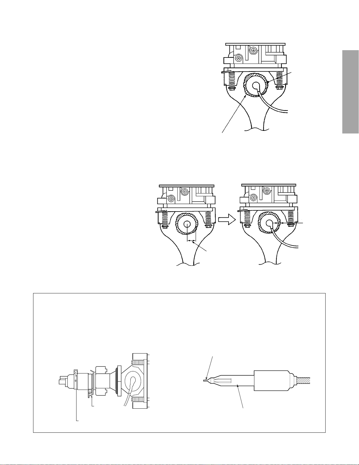
Anode Cap
GENERAL ADJUSTMENTS
Silicon
(On shaded area)
TSE3843W #23960136
SERVICING PRECAUTIONS
■ Do not use a magnetized screw driver for screws
of Deflection Yoke and Velocity Modulation Coil to
avoid magnetization of electron gun.
Magnetization of electron gun will degrade basic
function and result in unbalance of right and left
shift of user static convergence, and result in no
variable quantity.
2 ~ 5 mm
SPECIFIC INFORMATIONS
15 ~ 25 mm
■ When replacing the anode cap assembly (CRT) or
anode lead assembly (F.B.T.), remove the anode
lead holder from old one and attach the holder
again to new anode lead.
■ Check the point of anode lead in a straight
line, if it is winding, please revise it.
Screw for
D.Y
Screw for SVM coil
Anode lead holder
– 5 –
WARNING : BEFORE SERVICING THIS CHASSIS, READ THE “X-RAY RADIATION PRECAUTION”, “SAFETY PRE-
CAUTION” AND “PRODUCT SAFETY NOTICE” ON PAGE 3 OF THIS MANUAL.
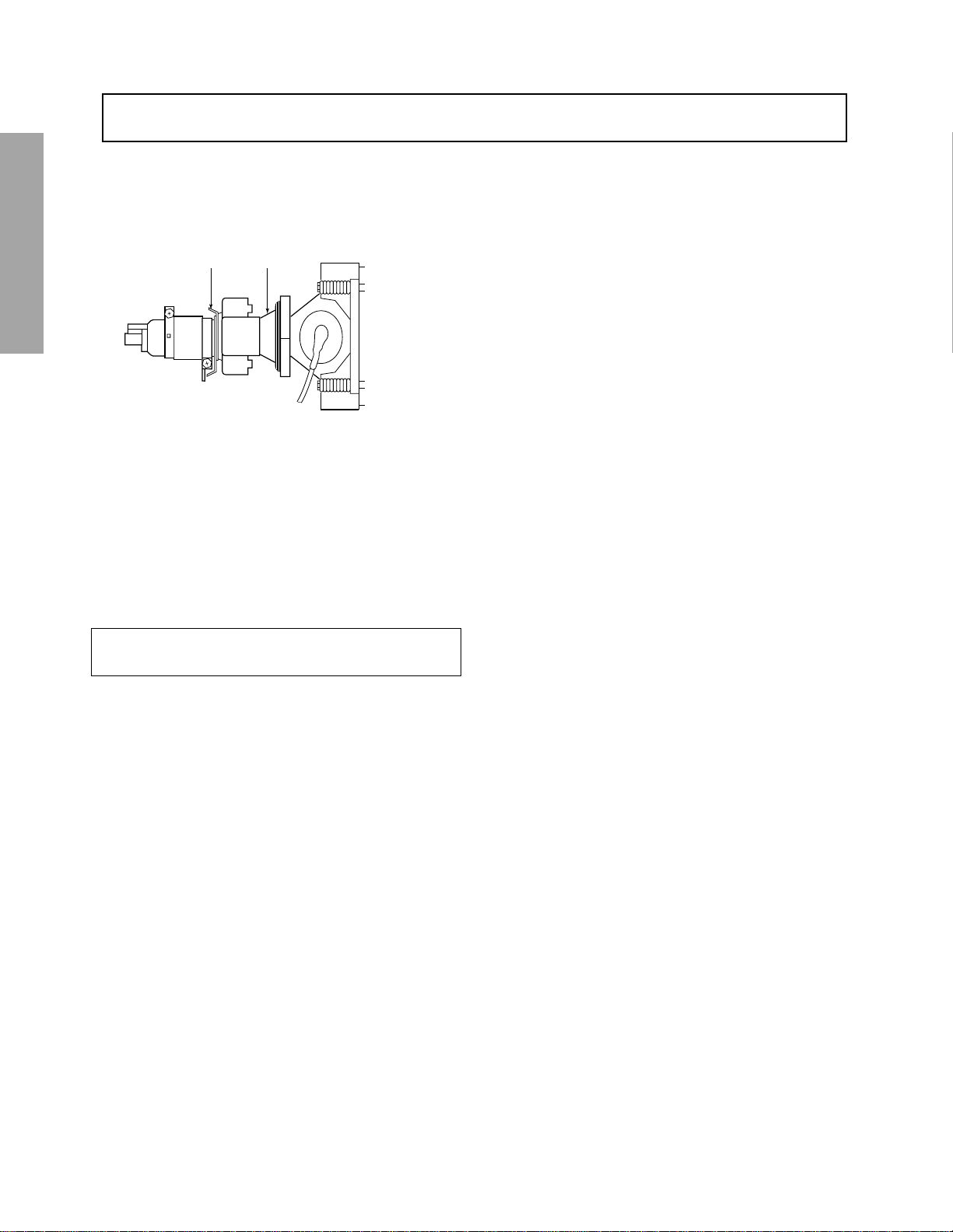
DESCRIPTION OF NECK COMPONENTS
GENERAL ADJUSTMENTS
Deflection yoke and convergence yoke
The position on the neck is required most front
(CRT funnel side) and the screw is fastened after
rotating yoke adjusting picture tilt.
Centering magnet
After adjusting picture tilt, picture position is finally
fixed by this magnet.
In order to get maximum margin of user conver-
SPECIFIC INFORMATIONS
gence control for center of screen, this magnet
have to be used for center convergence adjustment.
PICTURE TUBE COMPONENTS ADJUSTMENT
PREPARATION
Operate the receiver for at least 5 minutes.
– 6 –
R, G, B FOCUS ADJUSTMENT
1. Before adjusting the R, G, B FOCUS, remove the 4 screws
of Lens Assembly which is fixed on the CRT Assembly.
(See page 4.)
Then turn around the Lens Assembly by 180˚ to adjust
the fastening screw (Fig. a) and fasten the 4 screws to
secure Lens Assembly.
2. Select the adjustment mode. (See page 10.)
3. Press “7” button to display the built-in cross-hatch.
4. Press “0” and “RTN” buttons to make the picture a single
Red color.
100 button ................ to erase Red color
0 button .................... to erase Green color
RTN button .............. to erase Blue color.
5. Loosen the fasten screw and adjust Red lens focus to best
focusing point of picture center. Then fasten the screw.
(See Fig. a.)
Fig. a
6. Adjust FOCUS VR “R” of FOCUS PACK to find best fo-
cusing point of picture center.
7. Repeat steps 3 to 5 for Green and Blue colors.
TILT ADJUSTMENT
Rotate R, G, B deflection yoke so that picture becomes horizon, then fasten screw.
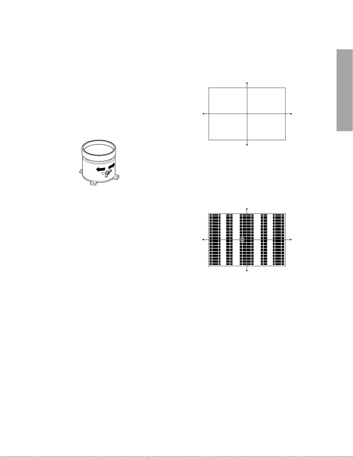
CENTERING ADJUSTMENT
1. Stretch a thread between two center of screen edge (top
and bottom, left and right).
GENERAL ADJUSTMENTS
2. Receive NTSC.
Then select SERVICE MODE. (See Page 10.)
3. Select CONVERGENCE ADJUSTING mode, and press
"7" button to display the built-in cross-hatch pattern.
Move Cursol and recognize horizontal line indicated Y:4.
This line is vertical center. Push "9" button to display the
vertical stripes, and recognaize horizontal center.
SPECIFIC INFORMATIONS
4. Perform VCEN adjustment. (See page 12.)
5. Adjust G centering magnet so that the cross-bar pattern
center comes to screen center.
6. Perform HEIGHT adjustment . (See page 13.)
7. Perform VERT. LINEARITY adjustment.
8. Perform WIDTH adjustment. (See page 12.)
9. Check whole quality of green line.
10
. Adjust R, B centering magnet so that the cross-bar pat-
tern center comes to screen center.
– 7 –
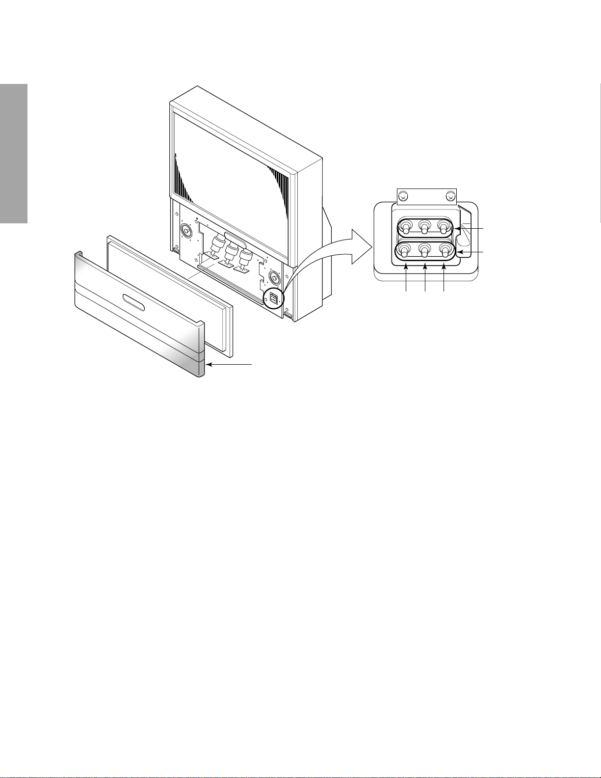
LOCATION OF SCREEN AND FOCUS VR’S
GENERAL ADJUSTMENTS
SCREEN VR
FOCUS VR
RGB
SPECIFIC INFORMATIONS
Speaker grille
– 8 –
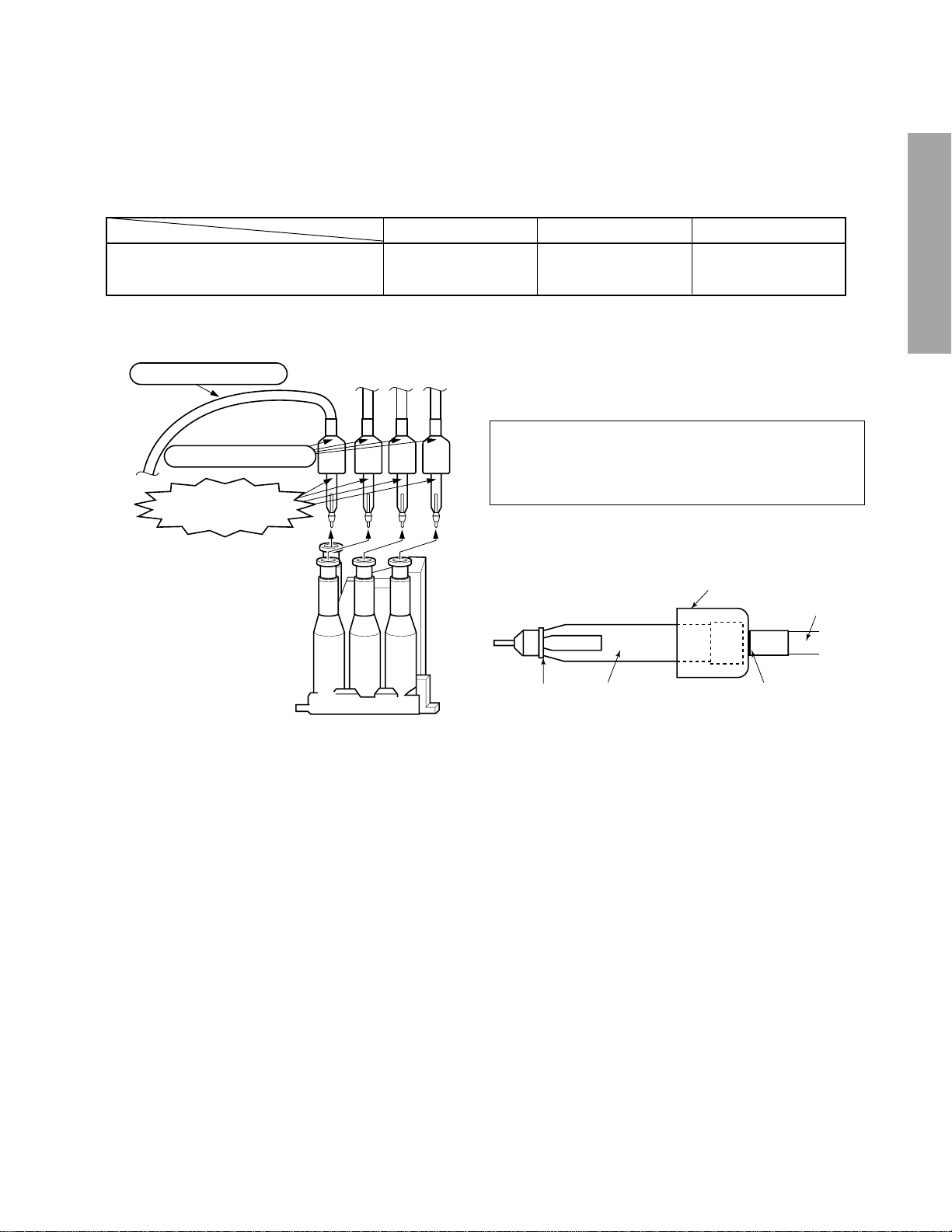
REPLACEMENT OF THE CRT
Service parts are provided for each R, G and B.
The contents of the parts are as follows.
HITACHI
CRT 23008174 23008175 23008176
RG B
REPLACEMENT OF HIGH VOLTAGE CABLE
ANODE LEAD
RUBBER BOOT
LEAD HOLDER
Z450 TPA5007
Fig. a
1. When replacing Anode Lead or Anode Cap with new one,
remove Lead Holder from old lead as shown in figure
below, and put it on new lead. Do not throw away Lead
Holder.
NOTE : THE LEAD HOLDER IS ATTACHED TO TPA5007
(Z450), BUT IS NOT ATTACHED TO ANODE
LEAD AND ANODE CAP. RUBBER BOOT IS ATTACHED TO ANODE LEAD AND ANODE CAP.
2. Detaching Lead Holder
RUBBER BOOT
LOCK LEAD HOLDER
Fig. b
Cut here rubber boot
and lead together to
detach Lead Holder.
OLD
ANODE LEAD
or
ANODE CAP
GENERAL ADJUSTMENTS
SPECIFIC INFORMATIONS
– 9 –
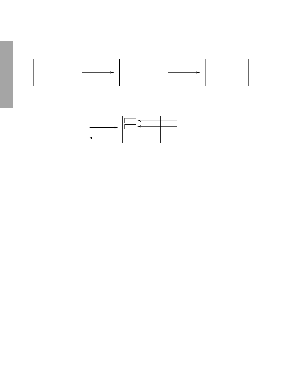
1. ENTERING TO SERVICE MODE
1) Press MUTE button twice
on Remote Control.
MUTE
SERVICE MODE
2) Press MUTE button
again to keep pressing.
3) While pressing the MUTE button,
press MENU button on TV set.
S
(Service mode display)
GENERAL ADJUSTMENTS
2. DISPLAYING THE ADJUSTMENT MENU
1) Press MENU button on TV.
Service mode
3. KEY FUNCTION IN THE SERVICE MODE
The following key entry during display of adjustment menu provides special functions.
SPECIFIC INFORMATIONS
Screen adjustment mode ON/OFF: TV (ANT)/VIDEO button (on TV)
Selection of the adjustment items : Channel s/t (on TV or Remote)
Change of the data value : Volume s/t (on TV or Remote)
Adjustment menu mode ON/OFF : MENU button (on TV)
Initialization of the memory (QA02) : RECALL+Channel button on TV (s)
Initialization of the self diagnostic data: RECALL+Channel button on TV (t)
“RCUT” selection : 1 button
“GCUT” selection : 2 button
“BCUT” selection : 3 button
“SCNT” selection : 4 button
“SCOL” selection : 5 button
“TNTC” selection : 6 button
Convergence adj : 7 button
Self diagnostic display : 9 button
Adjustment mode
S
Press
Press
Item
Data
– 10 –
4. SELECTING THE ADJUSTING ITEMS
1) Every pressing of CHANNEL s button in the service mode changes the adjustment items in the order of table-2.
(t button for reverse order)
Refer to table-2 for preset data of adjustment mode.
(See SETTING & ADJUSTING DATA on page 19)
5. ADJUSTING THE DATA
1) Pressing of VOLUME s or t button will change the value of data in the range from 00H to FFH. The variable range
depends on the adjusting item.
6. EXIT FROM SERVICE MODE
1) Pressing POWER button to turn off the TV once.
■ INITIALIZATION OF MEMORY DATA OF QA02
After replacing QA02, the following initialization is required.
1. Enter the service mode, then select any register item.
2. Press and hold the RECALL button on the Remote, then press the CHANNEL s button on the TV. The initialization of QA02
has been complated.
3. Check the picture carefully. If necessary, adjust any adjustment item above.
Perform “Programming Channel Memory” on the owner's manual.
CAUTION: Never attempt to initialize the data unless QA02 has been replaced.
7. SELF DIAGNOSTIC FUNCTION
1) Press “9” button on Remote Control during display of adjustment menu in the service mode.
The diagnosis will begin to check if interface among IC’s are executed properly.
2) During diagnosis, the following displays are shown.
GENERAL ADJUSTMENTS
SELF CHECK
NO. 23 * * * * * *
POWER : 000
BUS LINE : OK
BUS CONT : OK
BLOCK : MAIN SUB
SET ID : 01
EEP VER : 02
OPT1 : 05 OPT2 : 70
Part number of microprocessor (QA01)
Operation number of protection circuit (current limiter) . . . . “000” is normal.
BUS line check “OK” ................... Normal
“SCL-GND” or “NG” ........... SCL-GND short circuit
“SDA-GND” or “NG” ........... SDA-GND short circuit
“SCL-SDA” or “NG” ............ SCL-SDA short circuit
BUS line ACK (acknowledge) check
“OK” ..................... Normal
Display of Location Number . . . . NG
(Display example)
“QA02 NG”, “H001 NG”, “Q501 NG” etc.
Note: The indication of failure place is only one place though failure places are plural. When
repair of a failure place finishes, the next failure place is indicated. (The order of priority of
indication is left side.)
Sync. signal check Green display ..... Normal
Red display ........ NG
MAIN ........ Main sync
SUB .......... Sub sync (when turn on the PIP)
ID code for TV Set
Version of "EEP"
Data for "OPT"
SPECIFIC INFORMATIONS
– 11 –
ELECTRICAL ADJUSTMENT
ITEM ADJUSTMENT PROCEDURE
ƒH
(free-running frequency of Hor.
oscillator)
VERTICAL POSITION (VCEN)
GENERAL ADJUSTMENTS
PICTURE POSITION
(HPOS)
WIDTH
(WID)
SPECIFIC INFORMATIONS
1. Receive NTSC signal.
2. Short the terminal “TP +9V ” and the terminal “ TP (Free run) ” on the signal board with a jumper
wire.
3. Connect the probe of frequency counter to the lead of R426 and GND.
4. Adjust the frequency to “33.75±0.2 kHz” by turning R4034 on DPC Board.
5. Disconnect the shorted wire, then confirm that the picture is synchronized.
1. Receive NTSC signal.
2. Connect he probe of digital voltmeter to TP-V and TP-G on SIGNAL Board.
3. Call up the adjustment mode display, then select the item VCEN.
4. Press the VOLUME s or t button to get the voltage 0±10 mV.
1. Receive NTSC signal.
2. Call up the adjustment mode display.
3. Select the item “HPOS”, and adjust the data to “80H”.
4. Adjust the picture position alternately by turning CENTERING MAGNETS for proper picture
position.
5. Check the picture with off-air signal.
1. Receive NTSC signal.
2. Select the "FULL" mode by PIC SIZE button on Remote Control.
3. Call up the adjustment mode display, then select the item WID.
4. Press the VOLUME s or t button to get the picture so that left and right eddes of video signal
begin to lack.
5. Press the VOLUME s button to advance the data by 8 steps.
NOTE: Check the horizontal picture position is correct.
SUB-BRIGHTNESS
(BRTC)
SUB-COLOR
(SCOL)
1. Receive the air signal or aux Video signal.
2. Enter sports mode on user menu.
3. Enter the service mode, then select “BRTC” register.
4. Adjust the data to set dark area of picture to proper level.
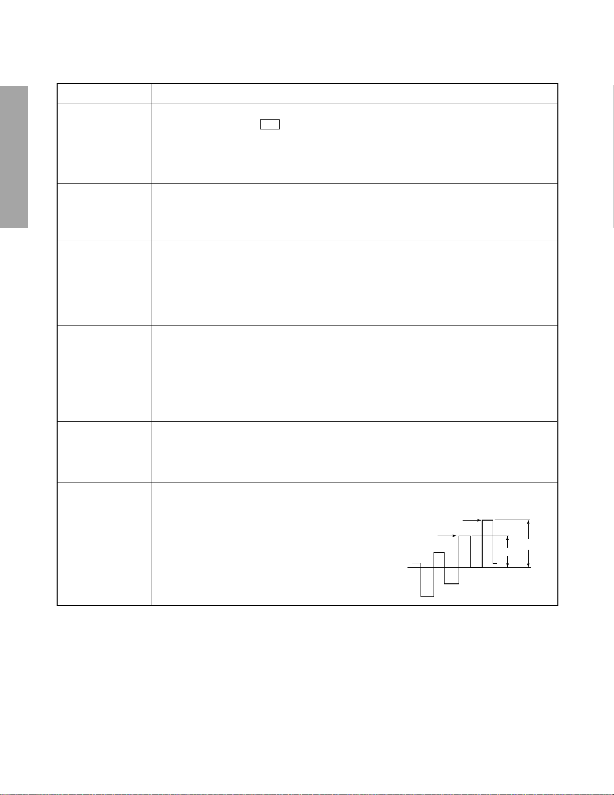
1. Receive color-bar signal from color-bar generator.
2. Adjust the BRIGHTNESS and CONTRAST to the center (RESET status).
3. Connect oscilloscope to TP501on the MAIN board.
4. Enter the service mode, then select “SCOL”.
5. Adjust the data value to achieve 1.8V
of blue bar on
0-p
Magenta
Blue
scope.
6. Check the picture with off-air signal.
0
2
3 (1.8V
0-P
)
– 12 –
ITEM ADJUSTMENT PROCEDURE
HEIGHT
(HIT)
VERTICAL LINEARITY
(VLIN)
(FULL mode only)
WHITE BALANCE
(RCUT)
(GCUT)
(BCUT)
(RDRV)
(BDRV)
1. Receive NTSC signal.
2. Select the "FULL" mode by PIC SIZE button on Remote Control.
3. Call up the adjustment mode display and select the item HIT.
4. Press the VOLUME s or t button to get the picture so that top and bottom of
video signal begin to lack.
5. Press the VOLUME s button to advance the data by 8 steps.
Note: Check the vertical picture position is correct.
Adjust the data of height after vertical linearty.
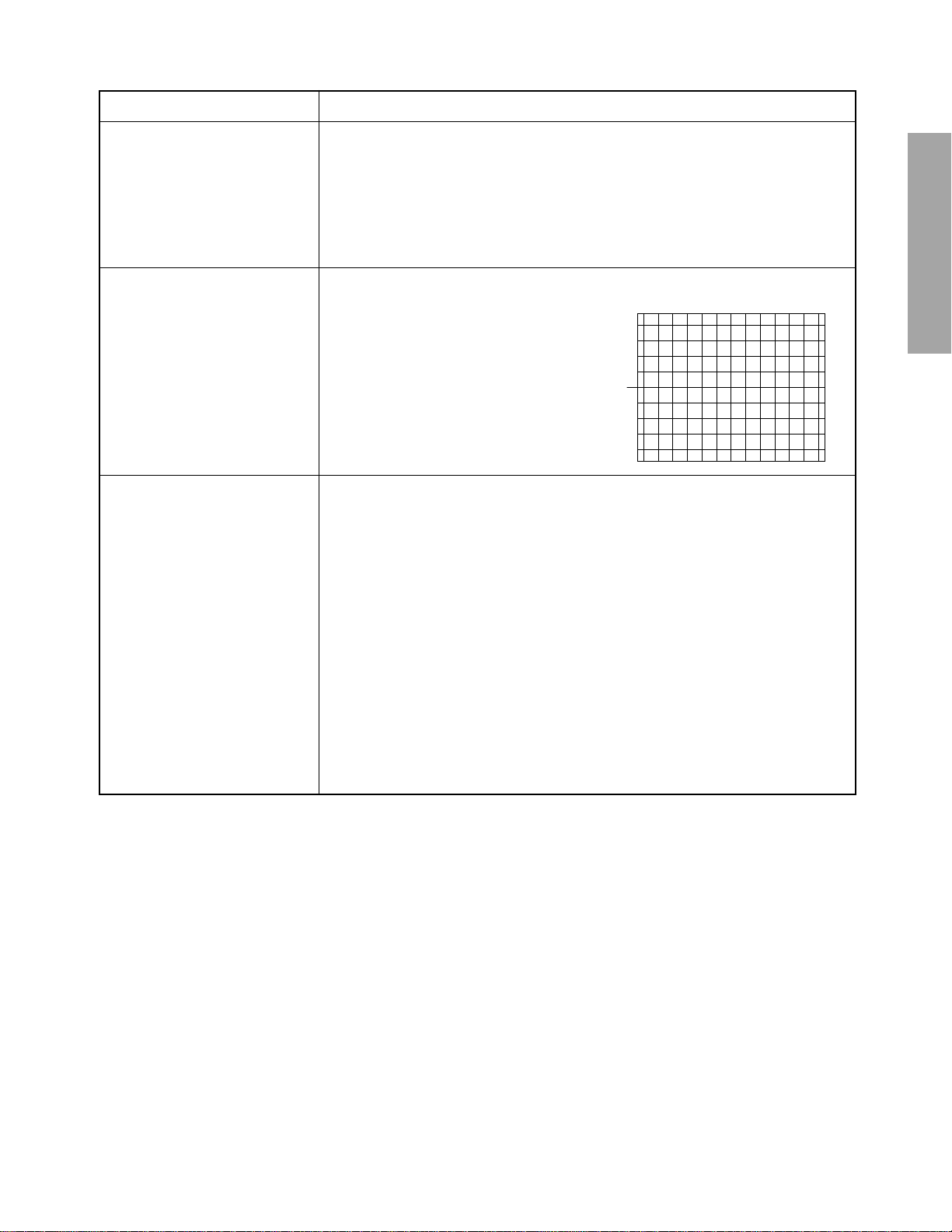
1. Receive cross-hatch pattern.
2. Call up the adjustment mode display, then select the item VLIN.
3. Press the VOLUME s or t button to obtain
the picture of the best linearity.
4. Then readjust the item HIT.
1. Press RESET button on TV or remote hand set.
2. Call up the adjustment mode display, then adjust the data of items RCUT, GCUT
and BCUT to “80”.
3. Press TV (ANT)/VIDEO button on TV.
4. Gradually rotate R, G and B SCREEN volume of FOCUS PAC (page 9) clockwise or counterclockwise until the raster appears slightly on the CRT through
the each lens, and leave them.
(Look into the lens in order to check the raster.)
5. Press TV (ANT)/VIDEO button on TV again.
6. Exit from service mode.
7. Receive white laster pattern signal, and adjust the contrast to the minimum to
make white picture to low light.
8. Adjust the data of items RCUT, GCUT and BCUT for low light area.
9. Adjust the contrast to the maximum to make white picture to high light.
10. Adjust the data of items RDRV and BDRV Controls for proper white-balanced
picture in high light area.
11. Check the white balance in both low and high light areas. If necessary, perform
again steps from 7 to 9.
GENERAL ADJUSTMENTS
SPECIFIC INFORMATIONS
– 13 –

CONVERGENCE ADJUSTMENT
Adjust convergence from center to circumference in order.
KEY FUNCTION IN THE CONVERGENCE ADJUSTMENT:
Lord BACK UP DATA: 1 button
Up : 2 button
Selet Green color: 3 button
Left : 4 button
Blinking of cursor ON/OFF: 5 button
GENERAL ADJUSTMENTS
SPECIFIC INFORMATIONS
Right: 6 button
Adjust mode ON/OFF: 7 button
Down: 8 button
Vertical stripe ON/OFF 9 button
Erase Green line: 0 button
Erase Red line: 100 button
Erase Blue line: ENT button
Note:
Adjusting procedure in replacing convergence board.
1. User convergence center check. Make sure the best
convergence setting is about the center of adjustable
range.
2. CENTERING ADJUSTMENT
3. PICTURE POSITION ADJUSTMENT
4. HIT, WID ADJUSTMENT
5. CONVERGENCE ADJUSTMENT
6. Execute TOUCH FOCUS following instructions displayed
on the screen after finishing CONVERGENCE ADJUSTMENT.
7. If TOUCH FOCUS ERROR is displayed after finishing
TOUCH FOCUS, the method of CROSS-HATCH PATTERN after CONVERGENCE adjustment is different from
what is exhibited on the right figure, or HARDWARE is out
of order.
1. Select the adjustment mode following the steps on page
10.
RCUT
40H
2. Press “7” button to display the built-in cross-hatch pattern
and press "9" button to display the vertical stripes.
3. If there is need to load BACKUP DATA, push "1" button,
and then push "ENTER" button according to following
message. Convergence become adjusted state at factory
by this action.
If there is no need, pass this process.
Never to use this function to new convergence board,
because BACKUP DATA is not exist.
4. Adjustment around cursor can be done.
The pattern includes three colors (R, G, B).
The cursor should be blinking in Red.
This means that the Red color is adjustable.
5. Press “3” button to select Green color to be adjusted.
6. Press “5” button to stop the blinking of cursor.
7. Press “2 (up)”, “8 (down)”, “4 (left)” or “6 (right)” to obtain
the correct cross-hatch pattern as above.
If necessary, the specified color line can be erased from
the screen.
100 button ...................... to erase Red line
0 button ...................... to erase Green line
CH RTN button ...................... to erase Blue line
8. Press “5” button to make the cursor blinking.
9. Press “2”, “8”, “4”, “6” buttons to move the cursor to other
point to be adjusted.
10. Repeat steps 6 to 9.
11. Repeat steps 5 to 10 to adjust Red and Blue colors.
Converge the selected color line into the Green line.
12. Press “7” button to memorize the adjusted states.
At this time, picture changes for about 1 second.
13. Press the TOUCH FOCUS button when "PLEASE PUSH
TOUCH FOCUS" is displayed on the screen.
14. TOUCH FOCUS CALIBRATION MODE is executed.
15. It returns to the normal screen after displaying
"CALIBRATION FINISHED".
– 14 –
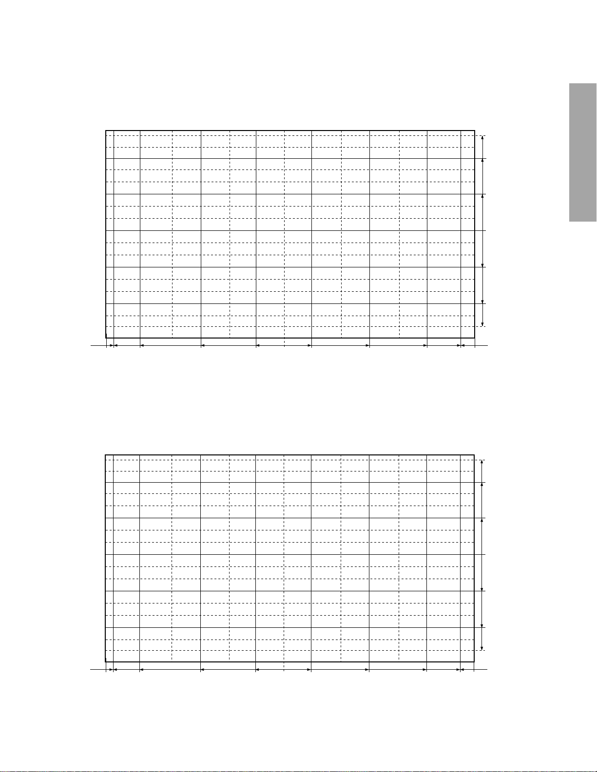
Adjusting Dimension of Each Picture Screen
(16:9 screen size:) 50 inches
(1) HD (1080I/NTSC)
50 inches 16:9 Screen Size:horizontal 1106mm :Vertical 622mm
(QH173, 16KB, CHIP1, UFO-*,BANK1) Vspan37.7mm Hspan88.5
301.6
226.2
113.1
GENERAL ADJUSTMENTS
0
113.1
226.2
301.6
22.0 531.0 442.5 265.5 088.5 88.5 265.5 442.5 531.0
Adjusting Dimension of Each Picture Screen
(16:9 screen size:) 65 inches
(1) HD (1080I/NTSC)
65 inches 16:9 Screen Size:horizontal 1442mm :Vertical 810mm
(QH173, 16KB, CHIP1, UFO-*,BANK1) Vspan49.1mm Hspan115.0
22.0
SPECIFIC INFORMATIONS
392.3
294.3
147.3
0
147.3
294.3
31.0 690.0 575.0 345.0 0115.0 115.0 345.0 575.0 690.0
– 15 –
392.3
31.0

NOTES
In many cases, color misconvergence may be corrected by returning HIT and WID data in main deflection side to initial adjusting
values. Following cases will surely require readjustment of convergence.
CRT REPLACEMENT
When CRT is replaced, main deflection readjustment and color matching are required.
Perform following procedures.
1. Replace two CRT’s of blue and red.
2. Perform horizontal adjustment for blue and red yokes on base of green CRT data. Mount yoke and velocity mod. coil alignment, pushing towards CRT without gap.
3. Adjust alignment of blue and red. (Refer Alignment adjustment for details.)
4. Rotating centering magnet, adjust CRT centers of red and blue to CRT center of green.
(Picture position adjustment)
5. Adjust HIT and WID data of main deflection, and decide data at the most precise screen comparing to green data.
GENERAL ADJUSTMENTS
SPECIFIC INFORMATIONS
6. Adjust convergence of screen picture for color matching. Do not move green one at this time.
7. After convergence adjustment of screen picture finishes, replace green CRT.
For green CRT as well, repeat steps 2 to 5 above on bases of red and blue color matching to adjust convergence.
8. Execute TOUCH FOCUS following instructions displayed on the screen after finishing convergence adjustments of all the
colors.
Note: Press button "7" again after "PLEASE PUSH TOUCH FOCUS" has been displayed. Then, TOUCH FOCUS will not be
executed, and the current state of convergence will be displayed.
REPLACING CONVERGENCE UNIT
When replacing convergence unit, picture screen require readjustment basically, but the following method allows process be
reduced considerably.
1. Replace the memory (Q713) on defective unit with memory on new unit. Mounting the unit on the SET after the above
working realizes picture screen before replacement immediately.
2. Mount unit which has old memories, on SET and turn it on. Screen shows whole picture looks like straightly shifted towards
vertical or horizontal direction.
3. Adjust again centers of green, red and blue with centering magnets.
4. Check picture screen for slight disparity of color and picture size. If necessary, add some adjustments of main deflection and
color matching of convergence.
5. Execute TOUCH FOCUS following instructions displayed on the screen after finishing convergence adjustments of all the
colors.
Note: Press button "7" again after "PLEASE PUSH TOUCH FOCUS" has been displayed. Then, TOUCH FOCUS will not be
executed, and the current state of convergence will be displayed.
– 16 –
SCREEN AND MIRROR ALIGNMENTS
ASSEMBLING OF FRONT SCREEN
K503 FRONT PANEL
LENTICULAR
K501
<OUTSIDE>
SMOOTH
K502
FRESNAL
BLACK STRIPES
SMOOTH
<INSIDE>
SPACER
FRONT PANEL
LENTICULAR
FRESNEL
INSIDE
OUT SIDE
LENS
BLACK STRIPES
0 to 1 mm
MOUNTING OF FRONT SCREEN
FRESNEL
LENTICULAR
FRONT PANEL
BEZEL
GENERAL ADJUSTMENTS
SMOOTH
SPECIFIC INFORMATIONS
CAUTION : Do not hold the optical system parts (lens and
mirror) with bare hand to avoid finger-prints on
the surface of those parts.
HOW TO CLEAN LENS AND MIRROR
1. Be sure to remove sand dust with an air brush, etc.
2. When it is stained slightly, breathe upon it and wipe away
with the specified cleaning cloth.
For other stains than the above, wipe the stains away with
the specified cloth into which a cleaning liquid has been
soaked.
Cleaning liquid.................... LENS LUSTER (Manufac-
tured by Edmund Scientific
Co.), etc.
HOW TO CLEAN SCREEN
When cleaning the screen, use a soft cloth so as not to
damage the screen.
1. Wipe the screen with a dry cloth to remove moisture on
the screen.
Note : Absolutely do not use detergent, water, alcohol,
benzine, thinner, etc. for cleaning in order not to
wipe away the black print on the surface.
– 17 –
CIRCUIT CHECKS
HIGH VOLTAGE CHECK
CAUTION: There is no HIGH VOLTAGE ADJUSTMENT on
this chassis. Checking should be done following
the steps below.
1. Connect an accurate high voltage meter to the anode of
the picture tube.
2. Turn on the receiver. Set the BRIGHTNESS and CONTRAST to minimum (zero beam current).
3. High voltage must be measured below (B) kV.
Refer to table-1 for high voltage (B).
(See SETTING & ADJUSTING DATA on page 19)
GENERAL ADJUSTMENTS
SPECIFIC INFORMATIONS
4. Vary the BRIGHTNESS to both extremes to be sure the
high voltage does not exceed the limit under any conditions.
CAUTION:
When the following parts fail, check the High Voltage after
replacing.
Location
No.
T461
C407
C408
C441
C432
C433
Name
Flyback
Capacitor
Capacitor
Capacitor
Capacitor
Capacitor
Descriptions
50", 65"
TFB3092AD
4700pF, ±3%
8200pF, ±5%
4700pF, ±3%
8200pF, ±5%
1200pF, ±3%
FS CIRCUIT CHECK
The Fail Safe (FS) circuit check is indispensable for the final
check in servicing. Checking should be done following the
steps below.
1. Turn the receiver on.
2. Temporarily short TP- (R) and TP- (X) on the DEF/POWER
Board with a jumper wire.
Raster and sound will disappear.
3. The receiver must remain in this state even after removing
the jumper wire. This is the evidence that the FS circuit is
functioning properly.
4. To obtain a picture again, temporarily turn the receiver off
and allow the FS circuit more than 5 seconds to reset. Then
turn the receiver on to produce a normal picture.
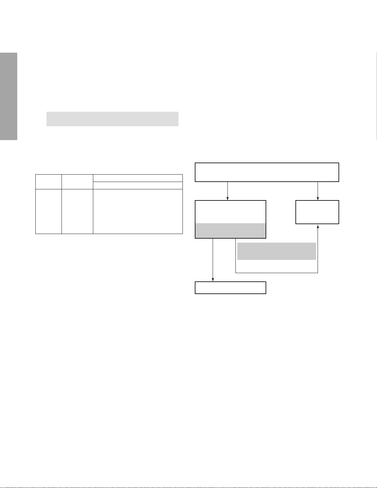
Troubleshooting Guide for Fail Safe Circuit
Check that the set returns to normal operation when
pin 12 of Z801 is grounded with jumper wire.
YES NO
Check the voltage across
Capacitor C419 is
approximately (
Refer to table –3 for
fall safe voltage (
C)
volts.
C)
.
Faulty power
circuit or horizontal circuit.
ANODE VOLTAGE MEASURING METHOD
CAUTION: Take extra precaution when measuring this high
voltage. High voltages are also present in
surrounding circuit boards (CRT DRIVE assembly, DEFLECTION assembly, and POWER
SUPPLY assembly).
1. Disconnect the FBT anode cable as outlined below. Measure high voltage at the point where the cable enters the
FBT.
2. Holding the rubber cover firmly, turn it counterclockwise
and check that the lock has been disengaged. (See Fig. b
on page 9.)
3. Determine the extent of the rubber cover before disconnecting the cable.
4. Pull straight up the anode cable to disconnect.
5. When reconnecting the cable, proceed in the reverse order.
After reconnecting, tug on the cable to check that it is secure.
YES
Defective Fail Safe Circuit
(See SETTING & ADJUSTING
DATA on page 19)
NO
– 18 –
 Loading...