

Toshiba 50H71 User Manual
OWNER'S MANUAL
Projection Television
®
Introduction
your TV
Connecting
Using the
Remote Control
Setting up
Using the TV’s
Appendix
Owner's Record
The model number and serial number are on the back
of your TV. Record these numbers in the spaces below.
Refer to these numbers whenever you communicate
with your Toshiba dealer about this TV.
your TV
Features
50H71
© 2001 TOSHIBA CORPORATION
All Rights Reserved
Model number:
Serial number:
50H71
Index
Important Information
Precautions
WARNING
TOREDUCETHERISKOFFIREORELECTRICSHOCK,DO
NOT EXPOSE THIS APPLIANCE TO RAIN OR MOISTURE.
The lightning symbol in the triangle tells you that the
voltage inside this product may be strong enough to
cause an electric shock. DO NOT TRY TO SERVICE
THIS PRODUCT YOURSELF.
The exclamation mark in the triangle tells you that
important operating and maintenance instructions
follow this symbol.
CAUTION
TO PREVENT ELECTRIC SHOCK, DO NOT USE THIS
POLARIZED PLUG WITH AN EXTENSION CORD
RECEPTACLE OR OTHER OUTLET UNLESS THE
PRONGS CAN BE FULLY INSERTED INTO THE
OUTLET TO PREVENT ANY EXPOSURE OF THE
PRONGS ON THE POLARIZED PLUG.
ATTENTION
POUR PRÉVENIR LES CHOCS ÉLECTRIQUES NE PAS
UTILISER CETTE FICHE POLARISÉE AVEC UN
PROLONGATEUR, UNE PRISE DE COURANT OU UNE
AUTRE SORTIE DE COURANT, SAUF SI LES LAMES
PEUVENT ÊTRE INSÉRÉS À FOND SANS EN LAISSER
AUCUNE PARTIE À DÉCOUVERT.
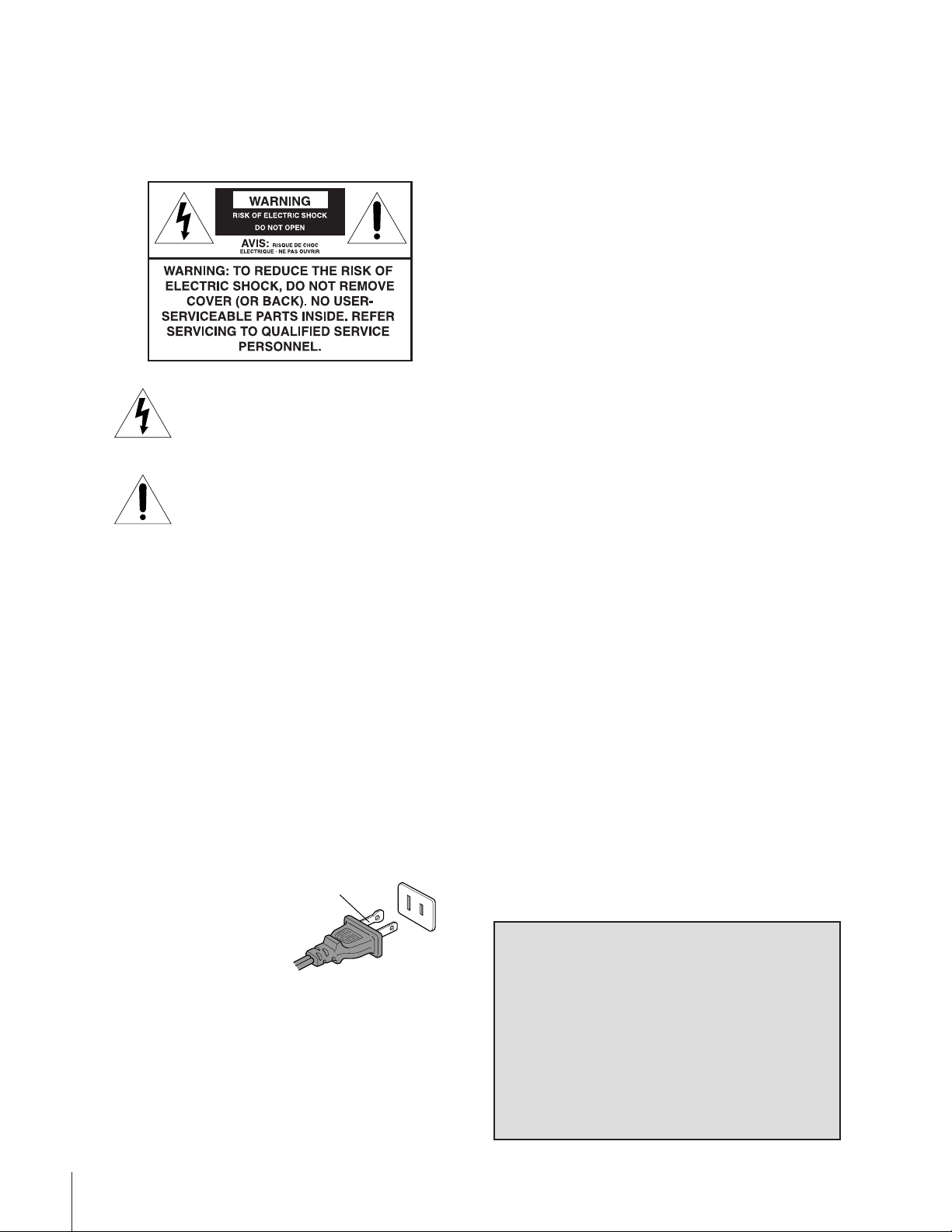
CAUTION
The plug has one prong wider than the other and will fit only
one way into a standard
electrical outlet (120 volt AC,
60 Hz). If the plug does not
fit into the outlet, try turning
it around. If the plug still does
not fit, the outlet is probably
non-standard and must be
replaced by a qualified electrician. Do not tamper with the plug
or try to force it into a non-standard outlet.
Note to CATV system installers in the USA
This reminder is provided to call the CATV system installer’s
attention to Article 820-40 of the NEC, which provides
guidelines for proper grounding, and, in particular, specifies that
the cable ground shall be connected to the grounding system of
the building, as close to the point of cable entry as practical.
Installing your TV
• Place the TV on the floor or on a sturdy platform. The
mounting surface should be flat and steady. If you install the
TV on a soft floor, make sure that the floor is not damaged
by the weight of the TV.
• Place the TV far enough away from the walls to allow proper
ventilation. This will prevent theTV from overheating and
avoid possible damage to the TV. Avoid dusty areas too.
• Damage may occur if you leave the TV in direct sunlight or
near a heater. Avoid areas subject to extremely high
temperatures or humidity, and temperatures of 41˚F(5˚C) or
lower.
Using your TV
• Do not stand or climb on the TV.
• Do not put any heavy object on top of the TV.
• Do not place containers with liquids such as drinks or
cosmetics on the TV. If any foreign material or water leaks
into the TV, unplug the AC cord and contact your dealer.
• If the room temperature suddenly rises, condensation may
occur on the lenses resulting in picture distortion or color
fading. In such a case, simply wait a while (with the power
on) and the condensation will evaporate.
• Avoid displaying stationary images on your TV screen for
extended periods of time. Stationary patterns generated by a
PIP/double-window display, computer displays, video games,
stock market reports, etc., can become permanently
engrained on the picture tube. This damage is not protected
by your warranty because it is the result of misuse. If you wish
to use your TV to display still images, reduce brightness and
contrast settings. Never leave a PIP/double-window,
computer, or video game display unattended.
• Sit approximately 10-25 feet away from the TV. Sitting too
far to the left or right of the screen will cause the picture to
appear dull as will direct sunlight and room lights. Turn the
TV off to check for reflections on the screen. Then remove
the source of any reflections while viewing.
Cleaning your TV
• Clean the TV with a soft, dry cloth. Never use strong solvents
such as thinner or benzine which might damage the finish of
the cabinet. If the cabinet is very dirty, use a damp cloth to
wipe the cabinet clean, then finish with a dry cloth.
NOTICE OF POSSIBLE ADVERSE EFFECTS ON TV PICTURE TUBE
Extensive viewing of fixed (non-moving) images or patterns can
cause uneven aging of the picture tube, and leave a subtle but
permanent ghost image in the picture. This type of damage is
NOTCOVERED BY YOUR WARRANTY
and unattended for long periods of time while the following
formats or images are displayed:
— Fixed images, such as PIP/POP windows, stock tickers,
video game patterns, TV station logos, and websites.
— Special formats that do not use the entire screen. For
example, viewing letterbox style (16:9) media on a normal
(4:3) display (bars at top and bottom of screen), or viewing
normal (4:3) media on a widescreen (16:9) display (bars on
left and right sides of screen).
. Never leave the TV on
2

Introduction................................................................ 4
Welcome to Toshiba......................................................... 4
Exploring your new TV ................................................... 4
Connecting your TV .................................................. 5
Connecting a VCR .......................................................... 5
Connecting a cable converter box .................................... 6
Connecting a cable converter box and VCR..................... 6
Connecting a DVD player or satellite receiver and
a VCR.............................................................................. 7
Connecting a DVD player with component video
and a VCR ....................................................................... 8
Connecting a DTV receiver/set-top box with
component video and a VCR ........................................... 9
Connecting two VCRs ................................................... 10
Connecting a camcorder ................................................ 10
Connecting an audio system .......................................... 11
Connecting an A/V receiver ........................................... 11
Using the remote control ...................................... 12
Preparing the remote control for use .............................. 12
Installing the remote control batteries ............................ 12
Using the remote control with a Toshiba VCR or
cable TV converter......................................................... 12
Programming the remote control for use with a
non-Toshiba VCR or cable TV converter .......................13
VCR code table ...................................................... 14
Cable TV converter
code table ............................................................... 15
Learning about the remote control ................................. 16
Setting up your TV .................................................. 17
Learning about the menu system ................................... 17
Changing the on-screen display language ....................... 18
Selecting the antenna input............................................ 18
Adding channels to the TV’s memory ............................ 19
Programming channels automatically...................... 19
Adding and erasing channels manually.................... 19
Changing channels ........................................................ 20
Adjusting the color convergence..................................... 21
Using the TV’s features.......................................... 22
Adjusting the channel settings........................................ 22
Switching between two channels .............................22
Programming your favorite channels ....................... 22
Labeling channels ................................................... 23
Viewing the wide-screen picture formats ........................ 25
Selecting the image shape........................................ 25
Watching PIP/double-window ....................................... 26
Switching the main and sub-pictures....................... 27
Changing the position of the small picture.............. 27
Freezing the sub-picture .......................................... 27
Using the multi-window feature..................................... 28
Using the favorite function ..................................... 28
Using the strobe function........................................ 28
Using the LOCKS menu ............................................... 29
Entering the PIN code ............................................ 29
Using the V-CHIP menu ............................................... 30
ENABLE BLOCKING .......................................... 30
TV RATING (Independent rating system for
broadcasters) ........................................................... 30
MPAA RATING (Independent rating system for
movies) ................................................................... 31
BLOCKING OPTION.......................................... 31
Unlocking programs temporarily ............................ 32
Locking channels ........................................................... 32
Locking video inputs ..................................................... 33
Using the front panel lock feature .................................. 34
Changing the PIN code ................................................. 34
Adjusting the picture ..................................................... 35
Selecting the picture mode ......................................35
Adjusting the picture quality ................................... 35
Saving new preference ............................................. 36
Using the flesh tone feature..................................... 36
Using the
Selecting the cinema mode...................................... 37
Selecting the color temperature ...............................37
Resetting picture adjustments ................................. 37
Selecting the video input source .....................................38
Labeling the video input sources .................................... 38
Using the closed caption feature..................................... 39
Setting the sleep timer.................................................... 40
Setting the clock ............................................................ 40
Adjusting the sound .......................................................41
Muting the sound ................................................... 41
Selecting stereo/SAP broadcasts .............................. 41
Using the SRS 3D surround sound feature ............. 42
Adjusting the sound quality .................................... 42
Resetting audio adjustments ................................... 43
Using the sub-bass system (SBS) ............................. 43
Turning off the built-in speakers ............................. 44
Selecting the Audio OUT sound............................. 44
Using the StableSound™ feature ............................ 45
Selecting the background of the menu display ............... 45
Displaying on-screen information .................................. 45
Viewing the demonstration mode .................................. 46
Understanding the auto power off feature ......................46
Understanding the last mode memory feature ................ 46
Digital Noise Reduction (DNR) feature ...
36
Appendix................................................................... 47
Specifications ................................................................. 47
Troubleshooting .............................................................48
Limited United States Warranty ..................................... 49
Index .......................................................................... 50
3
Introduction
Introduction
Welcome to Toshiba
Congratulations! You have purchased one of the finest projection TVs
on the market. The goal of this manual is to guide you through
setting up and operating your Toshiba TV as quickly as possible.
Instructions in this manual are based on using the remote control.
You can also use the controls on the TV if they have the same name as
those on the remote control.
your TV
Connecting
Please read all the safety and operating instructions carefully, and keep
the manual for future reference.
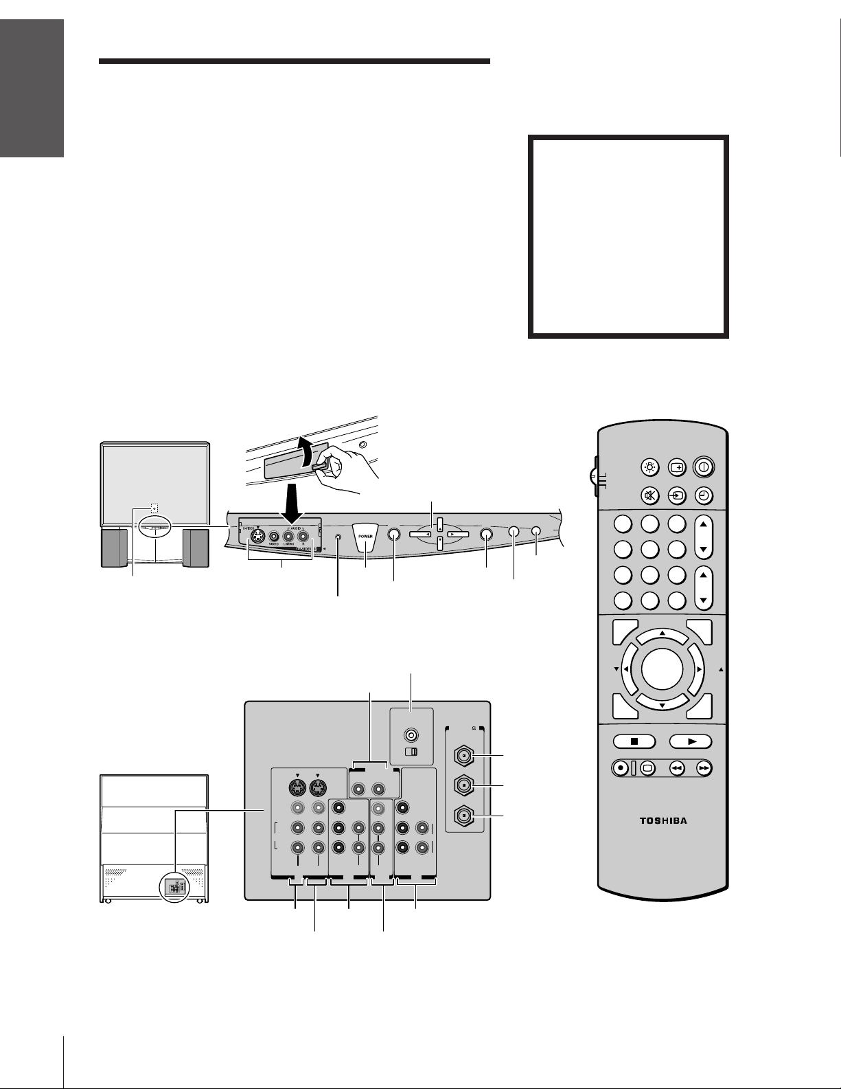
Exploring your new TV
You can operate your TV by using the buttons on the front panel or
the remote control. The back panel and front panel (behind the door)
provide all the terminal connections you will need to connect other
equipment to your TV. See “Connecting your TV” on page 5.
Using the
Remote Control
your TV
Setting up
Features
Using the TV’s
Appendix
TV front
Remote sensor
TV rear
Video/Audio inputs
(Video 3)
Power indicator
S-VIDEO
VIDEO
L/
MONO
AUDIO
R
VIDEO-1 VIDEO-2
IN
LIFT
POWER
Variable
Audio OUT
RL
Y
L
PB
PR
R
COLOR
STREAM
AUDIO
Channel yz
Volume x •
Menu yzx •
MENU
VOL VOL
MENU
Audio Center
Channel
AUDIO CENTER
CHANNEL IN
ON OFF
OUT
VAR
AUDIO
VIDEO
Y
L/
MONO
PB
PR
R
COLOR
STREAM
AUDIO
HD 2HD 1
OUT
ININ
AUDIO
Please Note
On some models, the SET UP
menu automatically appears onscreen the first time the TV is
turned on.
To change the menu settings, see
“Setting Up Your TV” on page 17
for details.
To close the menu, either press
EXIT or turn the TV off.
POWER
RECALL
LIGHT
TV
CABLE
MUTE
VCR
CH
EXIT
CH
TV/
VIDEO
DEMO
123
456
DEMO
EXIT
789
TV/VIDEO
0
100
PIP CH
FAVORITE
FAV
)
ANT( 75
ANT-1
ANT-1 IN
OUT
ANT OUT
ANT-2
L
R
ANT-2 IN
MENU/
ENTER
STROBE
PIP CH
STOP SOURCE
REC TV/VCR REW FF
STILL LOCATE SWAP
CT-90087
TV/VIDEO
ADV/
ADV/
CH RTN
ENT
TIMER
CH
VOL
PIC SIZE
FAV
EXIT
PLAY PIP
Index
VIDEO-1
ColorStream
VIDEO-2
HD1
ColorStream
Audio
HD2
OUT
4
Connecting your TV
S-VIDEO
Cable
If you have not connected electronic equipment before, or you have
been frustrated in the past, you may wish to read this section. (Cables
are not supplied.)
• A coaxial cable is the standard cable that comes in from your
antenna or cable converter box. Coaxial cables use “F”
connectors.
• Audio and video cables are usually color-coded according to use:
yellow for video and red and white for audio. The red audio cable
is for the stereo right channel, and the white audio cable is for
the stereo (or mono) left channel. If you look at the rear panel of
the TV, you will see that the terminals are color-coded in the
same manner as the cables.
• S-video cables provide better picture performance. S-video cables
can only be used with S-video compatible components.
• ColorStream
and provide the best picture performance. ColorStream cables
can only be used with ColorStream compatible components.
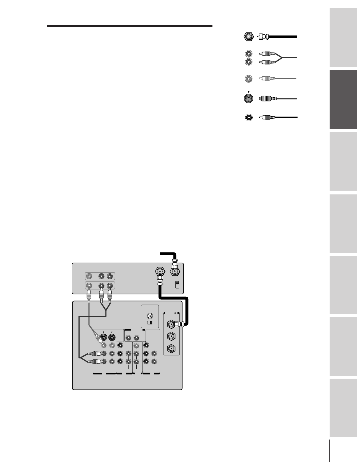
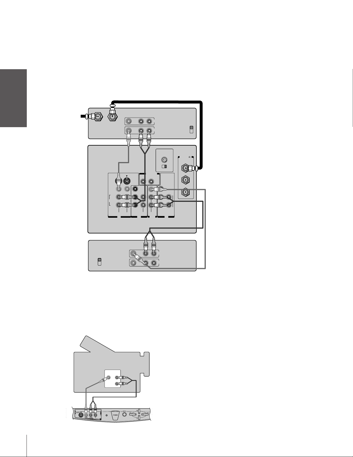
Connecting a VCR
This connection allows you to watch local channels and video
programs, play or record on the VCR while watching TV, and record
from one channel while watching another channel.
You will need:
• one coaxial cable
• one pair of audio cables (one single audio cable for a mono VCR)
• one video cable (one S-video cable for an S-VHS VCR)
®
(component video) cables come in sets of three
ANTENNA
Coaxial Cable
AUDIO
Cables
VIDEO
Cable
Color Stream
Cable
Caution:
Do not plug the TV in until you have finished
connecting all of your equipment.
Introduction
your TV
Connecting
Using the
Remote Control
your TV
Setting up
Stereo VCR
VIDEO AUDIO
TV
From Cable Box or Antenna
LR
IN
OUT
AUDIO CENTER
CHANNEL IN
ON OFF
OUT
S-VIDEO
VIDEO
L/
MONO
AUDIO
R
VIDEO-1 VIDEO-2
COLOR
STREAM
IN
RL
Y
L
P
B
P
R
R
AUDIO
AUDIO
OUT
VIDEO
L/
MONO
R
VAR
AUDIO
COLOR
STREAM
HD 2HD 1
OUT to TV
Y
L
P
B
AUDIO
P
R
R
ININ
IN from ANT
CH 3
CH 4
ANT( 75
ANT-1
OUT
ANT-2
Note:
If you have a mono VCR, connect L/Mono to
VCR Audio OUT using only one audio cable.
If you have an S-VHS VCR, use an S-video
cable (in the S-video jacks) instead of the
regular video cable.
Do not connect a regular video cable and an
)
S-video cable to Video-1 (or Video-2) at the
Features
Using the TV’s
same time.
Appendix
Index
5
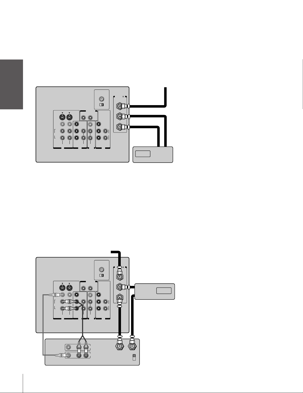
Connecting a cable converter box
This connection allows you to watch basic and premium cable
channels.
Introduction
To use the TV’s features, select ANT-1. To view premium channels,
select ANT-2, tune the TV to channel 3 or 4 (whichever channel is
vacant in your area), and use the converter box to change channels.
You will need:
TV From Cable
your TV
Connecting
Using the
Remote Control
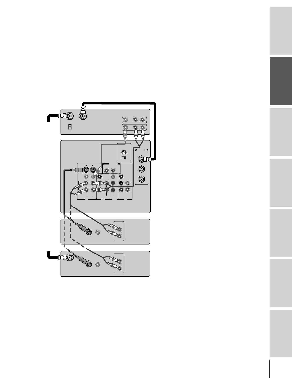
Connecting a cable converter box and VCR
• two coaxial cables
S-VIDEO
VIDEO
L/
MONO
AUDIO
R
COLOR
STREAM
VIDEO-1 VIDEO-2
IN
RL
Y
L
P
B
P
R
R
AUDIO
AUDIO
OUT
OUT
VIDEO
L/
MONO
R
VAR
AUDIO
AUDIO CENTER
CHANNEL IN
ON OFF
Y
P
B
AUDIO
P
R
COLOR
STREAM
HD 2HD 1
ININ
Note:
When you use a converter box with your TV,
the remote control will not operate some
features,such as programming your favorite
channels, labeling channels, and locking
channels.
)
ANT( 75
ANT-1
OUT
ANT-2
L
R
INOUT
Cable converter box
your TV
Setting up
Features
Using the TV’s
Appendix
This connection allows you to watch and record basic and premium
cable channels, watch videotapes, and record one channel while
watching another channel. To use the TV’s features, select ANT-1.
To view premium channels or record with the VCR, select ANT-2,
tune the TV to channel 3 or 4 (whichever channel is vacant in your
area), and use the converter box to change channels.
You will need:
• three coaxial cables
• one pair of audio cables (one single audio cable for a mono VCR)
• one video cable (one S-video cable for an S-VHS VCR)
COLOR
STREAM
From Cable
RL
Y
L
P
B
P
R
R
AUDIO
AUDIO
OUT
OUT
VIDEO
L/
MONO
R
VAR
AUDIO
AUDIO CENTER
CHANNEL IN
ON OFF
Y
P
B
AUDIO
P
R
COLOR
STREAM
HD 2HD 1
ININ
)
ANT( 75
ANT-1
OUT
IN
ANT-2
L
R
OUT
Cable converter box
TV
S-VIDEO
VIDEO
L/
MONO
AUDIO
R
VIDEO-1 VIDEO-2
IN
Note:
If you have a mono VCR, connect L/Mono to
VCR Audio OUT using only one audio cable.
If you have an S-VHS VCR, use an S-video
cable (in the S-video jacks) instead of a
regular video cable. Do not connect a regular
video cable and an S-video cable to Video-1
(or Video-2) at the same time.
When you use a converter box with your TV,
the remote control will not operate some
features, such as programming your favorite
channels, labeling channels, and locking
channels.
Index
LR
VIDEO
IN
OUT
LR
AUDIO
OUT to TV
IN from ANT
CH 3
CH 4
Stereo VCR
6
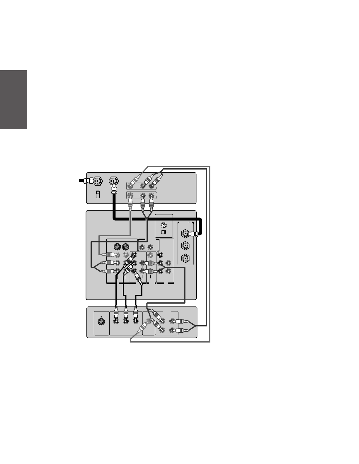
Connecting a DVD player or satellite receiver
andaVCR
This connection allows you to watch DVD/satellite, VCR, and TV
programs, and record one TV channel while watching another
channel.
You will need:
• one coaxial cable
• two pairs of audio cables (one single and one pair of audio cables
for a mono VCR)
• one video cable (between the TV and VCR)
• one S-video cable (between the TV and DVD player/satellite
receiver)
Stereo VCR
VIDEO AUDIO
LR
ANT( 75
ANT-1
OUT
ANT-2
IN
OUT
)
From
Antenna
IN from ANT
CH 3
CH 4
TV
OUT to TV
S-VIDEO
VIDEO
L/
MONO
AUDIO
R
VIDEO-1 VIDEO-2
AUDIO CENTER
CHANNEL IN
ON OFF
OUT
VAR
RL
AUDIO
VIDEO
Y
L
PB
PR
R
COLOR
STREAM
IN
AUDIO
AUDIO
OUT
L/
MONO
Y
L
PB
AUDIO
PR
COLOR
STREAM
HD 2HD 1
R
ININ
R
Note:
For the highest possible picture quality from a
non-ColorStream DVD player/satellite
receiver, you must use an S-video cable
between the TV and DVD player/satellite
receiver. (If your DVD player or satellite
receiver is ColorStream-compatible, see
page 8).
Do not connect both an S-video cable and a
regular video cable between the TV and DVD
player/satellite receiver at the same time.
Doing so will distort the picture.
Do not connect the DVD player/satellite
receiver and VCR to the same video channel
on the TV. (See the illustrations, which show
the DVD player/satellite receiver connected to
Video-1 on the TV and the VCR connected to
Video-2 on the TV.)
Caution:
The unauthorized recording of television
programs, videotapes, and other materials
may infringe upon the provisions of copyright
laws.
Introduction
your TV
Connecting
Using the
Remote Control
your TV
Setting up
From
Satellite
Dish
IN from ANT
S-VIDEO
S-VIDEO
VIDEO
OUTOUT
VIDEO
OUTOUT
DVD/Player
AUDIO
OUT
L
R
Satellite Receiver
AUDIO
OUT
L
R
Features
Using the TV’s
Appendix
Index
7
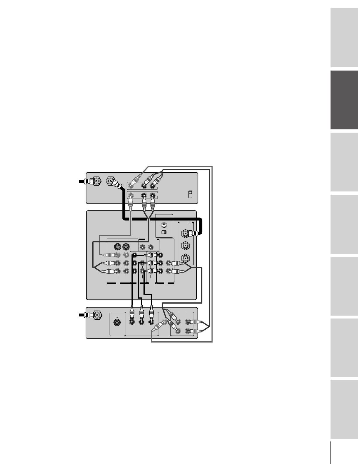
Connecting a DVD player with component
video and a VCR
This connection allows you to watch DVD, VCR, and TV programs,
Introduction
your TV
Connecting
Using the
Remote Control
your TV
Setting up
and record DVD and TV programs. You can record from one source
while watching a program from another source.
Your TV has ColorStream component video inputs. Connecting your
TV to a ColorStream-compatible DVD player (such as a Toshiba
ColorStream-equipped DVD player) can greatly enhance picture
quality and realism.
You will need:
• one coaxial cable
• three pairs of audio cables (two single and one pair of audio cables
for a mono VCR)
• two video cables
• one set of ColorStream (component video) cables (one S-video
cable for DVD player without component video; see note at
right)
Stereo VCR
From Antenna
IN from ANT
CH 3
CH 4
TV
OUT to TV
S-VIDEO
VIDEO
L/
MONO
AUDIO
R
VIDEO-1 VIDEO-2
IN
VIDEO AUDIO
LR
RL
Y
PB
PR
R
COLOR
STREAM
AUDIO AUDIO
L
OUT
OUT
VAR
AUDIO
VIDEO
L/
MONO
R
OUT
IN
AUDIO CENTER
CHANNEL IN
ON OFF
Y
PB
PR
COLOR
STREAM
HD 2HD 1
ININ
AUDIO
)
ANT( 75
ANT-1
OUT
ANT-2
L
R
Note:
For the highest possible picture quality, you
must use ColorStream video cables between
the TV and DVD player. You can connect the
ColorStream cables from the DVD player to
either ColorStream jack on the TV (HD1 or
HD2).
The ColorStream HD1 and HD2 jacks can be
used with Progressive (480p) and Interlace
(480i,1080i) scan systems.
If your DVD player is not ColorStreamcompatible, use the S-video connections
(both audio and video) instead of the
ColorStream connections. Do not connect
both S-Video and ColorStream cables
between the TV and DVD player at the same
time.
To record from the DVD player, set the VCR
to Line IN. To monitor recording from the
DVD player, set the VCR to Line IN, and set
the TV to Video-1.
Caution:
The unauthorized recording of television
programs, videotapes, and other materials
may infringe upon the provisions of copyright
laws.
Features
Using the TV’s
Appendix
Index
8
S-VIDEO
COMPONENT VIDEO
DVD player with component video
AUDIO
OUT
L
VIDEO
OUT
L
R
R
PRPBY
Connecting a DTV receiver/set-top box with
component video and a VCR
This connection allows you to watch DTV (digital TV broadcast),
VCR, and TV programs, and record DTV and TV programs. You can
record from one source while watching a program from another
source.
Your TV has ColorStream component video inputs. Connecting your
TV to a ColorStream-compatible DTV receiver can greatly enhance
picture quality and realism.
You will need:
• one coaxial cable
• three pairs of audio cables (two single and one pair of audio
cables for a mono VCR)
• two video cables
• one set of ColorStream (component video) cables (one S-video
cable for a DTV receiver without component video; see notes at
right)
Stereo VCR
From
Antenna
IN from ANT OUT to TV
TV
S-VIDEO
VIDEO
L/
MONO
AUDIO
R
VIDEO-1 VIDEO-2
VIDEO AUDIO
IN
COLOR
STREAM
LR
RL
Y
L
P
B
P
R
R
AUDIO AUDIO
OUT
OUT
VIDEO
L/
MONO
R
VAR
AUDIO
IN
OUT
AUDIO CENTER
CHANNEL IN
ON OFF
Y
P
B
P
R
COLOR
STREAM
HD 2HD 1
ININ
AUDIO
CH 3
CH 4
)
ANT( 75
ANT-1
OUT
ANT-2
L
R
Note:
For the highest possible picture quality, you
must use ColorStream video cables between
the TV and DTV receiver. You can connect the
ColorStream cables from the DTV receiver to
either ColorStream jack on the TV (HD1 or
HD2).
The ColorStream HD1 and HD2 jacks can be
used with Progressive (480p) and Interlace
(480i,1080i) scan systems.
If your DTV receiver is not ColorStreamcompatible, use the S-video connections
(both audio and video) instead of the
ColorStream connections. Do not connect
both S-Video and ColorStream cables
between the TV and DTV receiver at the same
time.
To record from the DTV receiver, set the VCR
to Line IN. To monitor recording from the DTV
receiver, set the VCR to Line IN, and set the
TV to Video-1.
Caution:
The unauthorized recording of television
programs, videotapes, and other materials
may infringe upon the provisions of copyright
laws.
Introduction
your TV
Connecting
Using the
Remote Control
your TV
Setting up
From
DTV Antenna
Satelite IN
S-VIDEO
Y
COMPONENT VIDEO
P
DTV receiver with component video
Features
AUDIO
OUT
L
VIDEO
OUT
L
R
R
RPB
Using the TV’s
Appendix
Index
9
Introduction
Connecting two VCRs
This connection allows you to record (dub/edit) from one VCR to
another VCR while watching a videotape. You can also record from
one TV channel while watching another TV channel.
You will need:
• one coaxial cable
• two pairs of audio cables (two single audio cables for mono
VCRs)
• two video cables (two S-video cables for S-VHS VCRs)
Caution:
The unauthorized recording of television
programs, videotapes, and other materials
may infringe upon the provisions of copyright
laws.
your TV
Connecting
Using the
Remote Control
your TV
Setting up
From Antenna
VCR1
IN from ANT OUT to TV
TV
S-VIDEO
VIDEO
L/
MONO
AUDIO
R
VCR2
CH 3
CH 4
VIDEO AUDIO
VIDEO-1 VIDEO-2
IN
LR
RL
Y
L
PB
PR
R
COLOR
STREAM
AUDIO AUDIO
OUT
VIDEO AUDIO
LR
IN
OUT
AUDIO CENTER
CHANNEL IN
ON OFF
OUT
VAR
AUDIO
VIDEO
L/
MONO
R
COLOR
STREAM
HD 2HD 1
IN
OUT
Note:
If you have S-VHS VCRs, use S-video cables
CH 3
CH 4
instead of regular video cables. Do not
connect both a regular video cable and an
S-video cable to Video-1 (or Video-2) at the
same time.
Do not connect the same VCR to the output
)
ANT( 75
ANT-1
OUT
Y
ANT-2
L
PB
AUDIO
PR
R
ININ
and input jacks on the TV at the same time.
To dub or edit, VCR 2 must select Line IN,
and the TV must select Video-1.
The Video OUT jack does not output the
*
*
**
PIP picture.
The Audio OUT jacks can output the sound
**
of either the Main or PIP picture (see
“Selecting the Audio OUT sound” on
page 44).
Features
Using the TV’s
Appendix
Index
10
Connecting a camcorder
This connection allows you to watch video materials recorded on a
camcorder.
You will need:
• one pair of audio cables
• one video cable (one S-video cable for an S-VHS camcorder)
Camcorder
VIDEO
AUDIO
OUT
L
R
Video-3 (front panel)
Caution:
If you have an S-VHS camcorder, use an
S-video cable between the S-video jacks on
the camcorder and TV. Do not connect both a
regular video cable and an S-video cable at
the same time.

OUT
RL
VAR
AUDIO
OUT
VIDEO
L/
MONO
IN
L
R
PB
PR
Y
L/
MONO
AUDIO
S-VIDEO
VIDEO
R
VIDEO-1 VIDEO-2
COLOR
STREAM
AUDIO
AUDIO
ININ
L
R
R
AUDIO
COLOR
STREAM
HD 2HD 1
PB
PR
Y
ANT( 75
)
ANT-1
CHANNEL IN
ON OFF
OUT
ANT-2
AUDIO CENTER
LINE IN
LR
Connecting an audio system
This connection allows you to use an audio amplifier to adjust the
audio level. This also allows you to use external speakers.
To control the audio, turn on the TV and the stereo amplifier, and
turn off the built-in speakers (see “Turning off the built-in speakers”
on page 44).
You will need:
• one pair of audio cables
Note:
To hear sound when using an external audio amplifier, the
volume of both the TV and the amplifier must be set
above 0 (zero).
Connecting an A/V receiver
This connection allows you to use an audio/video (A/V) receiver to
enhance your TV’s sound.
If you have a system with Dolby Pro Logic
add to the realism of the sound by using the TV’s internal speakers as
center channel speakers.
You will need:
• one pair of audio cables
• one single audio cable for the audio center channel
• one video cable
®
surround sound, you can
Amplifier
TV
Caution:
To avoid damaging the speakers, turn the TV
off before connecting or disconnecting the
Audio Center Channel audio cable.
Introduction
your TV
Connecting
Using the
Remote Control
To A/V Receiver
Video
OUT
TV
IN
Center
OUT
TV
AUDIO CENTER
S-VIDEO
VIDEO
L/
MONO
AUDIO
R
VIDEO-1 VIDEO-2
CHANNEL IN
ON OFF
OUT
VAR
RL
AUDIO
VIDEO
Y
L/
L
MONO
P
B
P
R
R
AUDIO
AUDIO
R
COLOR
STREAM
HD 2HD 1
OUT
COLOR
STREAM
IN
ANT( 75
ANT-1
OUT
Y
ANT-2
L
P
B
AUDIO
P
R
R
ININ
Note:
Refer to the instructions provided with your A/V receiver
for details about your surround sound system.
When the Audio Center Channel ON/OFF switch is in
the ON position, the TV speakers will function only as
center channel speakers.
Adjust the volume for the center channel speakers
using the center level control on the A/V receiver.
To use the TV speakers as normal speakers, set the
Audio Center Channel ON/OFF switch to the OFF
position.
From
Antenna
)
ON OFF
Dolby Pro Logic* surround sound
system connection example
Audio Video
VCR
Video
A/V receiver
Audio
Video
T V
Left
speaker
Surround
speaker L
_________
* Dolby Pro Logic is a registered trademark
of Dolby Laboratories Licensing
Corporation.
Audio
Audio
center
channel
Surround
speaker R
LDP/DVD
Right
speaker
11
your TV
Setting up
Features
Using the TV’s
Appendix
Index
Using the remote control
123
456
789
ENT
100
0
CH
VOL
POWER
TIMER
RECALL
TV/VIDEO
MUTE
TV
CABLE
VCR
CH RTN
PIC SIZE
EXIT
LIGHT
STOP SOURCE
ADV/
PIP CH
ADV/
PIP CH
FAV
FAV
PLAY PIP
REC TV/VCR REW FF
STILL LOCATE SWAP
FAVORITE
MENU/
STROBE
ENTER
Introduction
Preparing the remote control for use
With the remote control, you can operate your TV, most VCR
models, and cable TV converters together, even if they are different
brands. If you will be using your TV with a Toshiba VCR, your
remote control is already programmed and ready to use. If you own
different brands of VCRs and/or converters, you first have to program
your remote control. (See “Programming the remote control for use
your TV
with a VCR or a cable TV converter” on page 13.)
Connecting
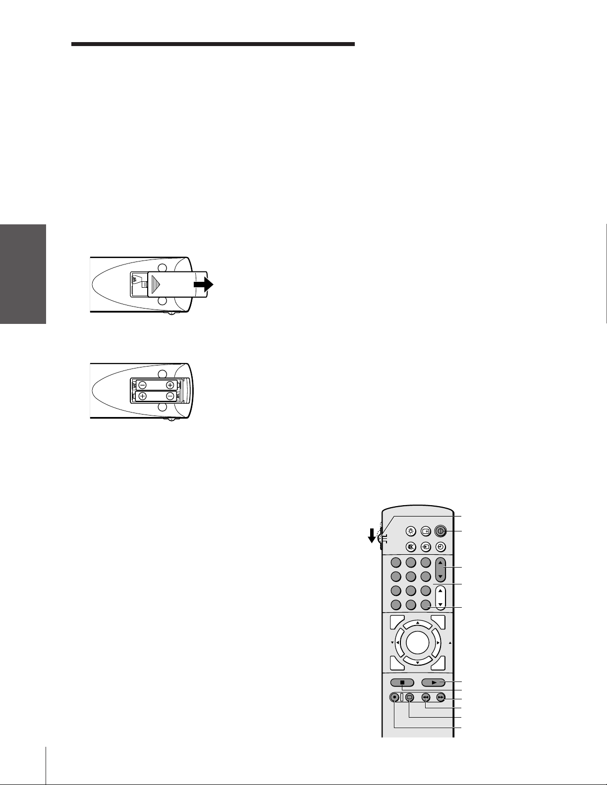
Installing the remote control batteries
To install the batteries:
Using the
Remote Control
your TV
Setting up
1. Slide the battery cover off the back of the remote control.
2. Install two “AA” size alkaline batteries. Match the + and - signs on
the batteries to the signs on the battery compartment.
Note:
Your TV’s remote control may not operate
certain features on your VCR, cable TV
converter, or other electronic device.
Refer to the owner’s manuals for your other
devices to determine their available features.
If your TV’s remote control does not operate a
specific feature on a device, use the remote
control that came with the device.
Caution:
• Dispose of batteries in a designated
disposal area. Do not throw batteries into a
fire.
• Do not mix battery types or combine used
batteries with new ones.
• If the batteries are dead or if you will not
use the remote control for a long time,
remove the batteries to prevent battery acid
from leaking into the battery compartment.
Note:
Battery life expectancy is about one year with
normal use.
Features
Using the TV’s
Appendix
Index
3. Slide the battery cover back on to the remote control until the
lock snaps.
Using the remote control with a Toshiba VCR or
cable TV converter
To control a Toshiba VCR:
Set the TV/CABLE/VCR switch to the VCR position. The
buttons shown at right will then control the VCR. The unshaded
buttons will operate the TV as usual.
To control a cable TV converter:
Set the TV/CABLE/VCR switch to the CABLE position. The
shaded buttons in the top half of the illustration at right will
control the cable TV converter. The other buttons will operate the
TV as usual.
If you own a non-Toshbia VCR or cable TV converter, you may be
able to program the TV remote control to control it. See
“Programming the remote control for use with a non-Toshiba VCR or
cable TV converter” on page 13.
TV/CABLE/VCR
POWER
Channel yz
Chanel
Number
Enter
PLAY
STOP
Fast Forward
Rewind
TV/VCR
Record
12
123
456
789
ENT
100
0
CH
VOL
POWER
TIMER
RECALL
TV/VIDEO
MUTE
TV
CABLE
VCR
CH RTN
PIC SIZE
EXIT
LIGHT
STOP SOURCE
ADV/
PIP CH
ADV/
PIP CH
FAV
FAV
PLAY PIP
REC TV/VCR REW FF
STILL LOCATE SWAP
FAVORITE
MENU/
STROBE
ENTER
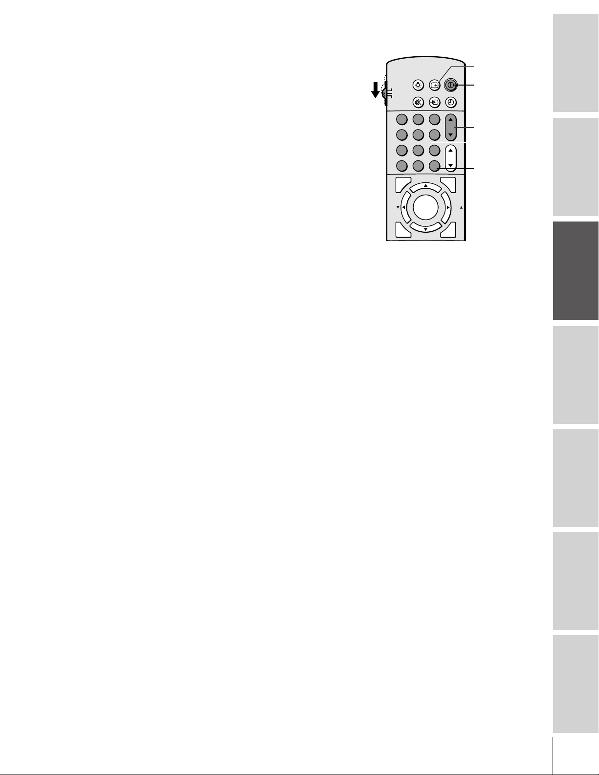
Programming the remote control for use with a
non-Toshiba VCR or cable TV converter
The remote control is pre-programmed to operate Toshiba VCRs. To
use the remote control to operate a non-Toshiba VCR or cable
converter, follow the steps below to program the remote control.
1. Refer to the “VCR code table” or “Cable TV converter code
table” on pages 14-15 to find the corresponding code for your
VCR or cable TV converter brand.
If more than one code is listed, try each one separately until you
find the one that works.
2. If you are reprogramming the remote control to operate your:
• VCR: Set the TV/CABLE/VCR switch on the remote control
to VCR.
• Cable converter: Set the TV/CABLE/VCR switch on the
remote control to CABLE.
3. While holding down the RECALL button, press the Number
buttons (0-9) to enter the three-digit code for your VCR or cable
TV converter.
4. Point the remote control at the VCR or converter and press
POWER to test the code.
If the VCR or converter responds, you have entered the correct
code.
If the VCR or converter does not respond, you may have entered
the wrong code. Repeat steps 1-4 using another code.
5. Reset the TV/CABLE/VCR switch to TV to control the TV.
For future reference, write down the code(s) you used:
VCR code _____________________
Cable TV converter code _____________________
RECALL
POWER
Channel yz
Channel
Number
Enter
Note:
• Each time you replace the batteries, you
must reprogram the remote control.
• Some newer VCRs are capable of working
on either of two remote codes. These VCRs
have a switch labeled “VCR1/VCR2.”
If your VCR has this kind of switch, it may
not respond to any of the code numbers for
your VCR brand name. In this case, set the
switch to the other position (VCR1 or
VCR2) and reprogram the remote control.
Introduction
your TV
Connecting
Using the
Remote Control
your TV
Setting up
Features
Using the TV’s
Appendix
Index
13

VCR code table
Introduction
your TV
Connecting
Using the
Remote Control
your TV
Setting up
Features
Using the TV’s
Appendix
Index
Brand name Code number
Adventura 019
Aiko 297
Aiwa 019
Akai 060,068,080,125,
261
American High 054
Asha 259
Audiovox 056
Beaumark 259
Bell & Howell 123
Brandt 206
Broksonic 140,203,230,314,
380
Calix 056
Canon 054
Capehart 039
Carver 100
CCE 091,297
Citizen 056,297
Colt 091
Craig 056,066,091,259
Curtis Mathes 054,060,079
Cybernex 259
Daewoo 039,064,297
Daytron 039
Dynatech 019
Electrohome 056
Electrophonic 056
Emerex 051
Emerson 019,021,056,062,
080,087,140,203,
227,228,230,231,
297,313,314,380,
498
Fisher 066,073,085,123
Fuji 052,054
Funai 019,344
Garrard 019,344
GE 054,079,084,221
Go Video 251,298
Goldstar 037,056,057
Gradiente 019
Harley Davidson 019
Harman/Kardon 057,094
Harwood 087,091
Headquarter 065
HI-Q 066
Hitachi 060,061,084,124,
254
Jensen 060
JVC 027,060,086
Kenwood 057,060,086
KLH 091
Kodak 054,056
Lloyd 019
Lloyd’s 227
Logik 091
LXI 056
Magnavox 054,058,100,129,
168
Magnin 259
Marantz 054,100
Marta 056
Masushita 054
MEI 054
Memorex 019,054,056,058,
065,066,067,123,
259
MGA 062,080
MGN Technology 259
Minolta 061,124
Mitsubishi 062,080,086,094,
192,233,261
Motorola 054,067
MTC 019,259
Multitech 019,091
Nad 077
NEC 057,059,060,069,
086
Nikko 056
Noblex 259
Olympus 054
Optimus 056,067,077,123
Optonica 081
Orion 498
Panasonic 054,096,181,244
Penney 054,056,057,059,
061,073,259
Pentax 061,084,124
Philco 054
Philips 054,081,100,129
Pilot 056
Pioneer 077,086
Portland 039
Protec 091
Pulsar 058
Quarter 065
Quartz 065
Quasar 054,096
Radio Shack 019,056,344
Radix 056
Randex 056
RCA 061,079,084,096,
124,125,168,221
Realistic 019,054,056,065,
066,067,081,085,
123,259
Ricoh 053
Runco 058
Samsung 064,259
Sanky 058,067
Sansui 060,086
Sanyo 065,066,123,259
Scott 062,064,140,203,
229,230,231
Sears 054,056,061,065,
066,073,085,123,
124
Sharp 067,081
Shintom 091
Shogun 259
Singer 091
Sony 051,052,053,054
STS 061
Sylvania 019,054,062,100,
129
Symphonic 019,344
Tatung 060
Teac 019,060
Technics 054,181
Teknika 019,054,056,071
Telefunken 060,206
TMK 227,259
Toshiba 062,064,085,229,
231,385
Totevision 056,259
Unitech 259
Vector 064
Vector Research 057,059
Video Concepts 059,064,080
Videosonic 259
Wards 019,054,061,066,
067,081,091,168,
231,259
XR-1000 019,054,091
Yamaha 057
Zenith 052,053,058
14

Cable TV converter
code table
Brand name Code number
ABC 020,022,026,027,
030,032,033,036,
066
Antronix 041
Archer 041,058,172
Belcor 075
Cable Star 075
Cabletenna 041
Cableview 041
Century 172
Citizen 172
Colour Voice 044,050
Comtronics 059,079
Contec 038
Dae Ryung 027
Eastern 021
Focus 419
Garrard 172
GC Electronics 035,075
Gemini 034,089
General Instrument 030,295
GoldStar 059,163
Hamlin 028,039,053,278,
292
Hitachi 030
Hytex 026
Jasco 172
Jerrold 022,030,031,033,
034,043,066,295
Macom 052
Magnavox 046
Memorex 019
Movie Time 175
NSC 089,175
Oak 026,038,267
Panasonic 019,040,126
Paragon 019
Philips 044,046,047,048,
049,050,172
Pioneer 042,163,552
Popular Mechanics 419
Pulsar 019
RCA 040
Recoton 419
Regal 039,278,292
Regency 021
Rembrandt 030,089
Runco 019
Samsung 059,163
Scientific Atlanta 025,027,036,296
Signal 034,059
Signature 030
SL Marx 059
Sprucer 040
Standard
Components 174
Starcom 022,034,066
Stargate 034,059
Starquest 034
Sylvania 020
Teleview 059
Texscan 020
Tocom 031,032,078
Toshiba 019
Tusa 034
Unika 041,172
United Artists 026
United Cable 022
Universal 041,058,075,096,
172,210
Viewstar 046,079,230
Zenith 019
Zentek 419
Introduction
your TV
Connecting
Using the
Remote Control
your TV
Setting up
Features
Using the TV’s
Appendix
Index
15
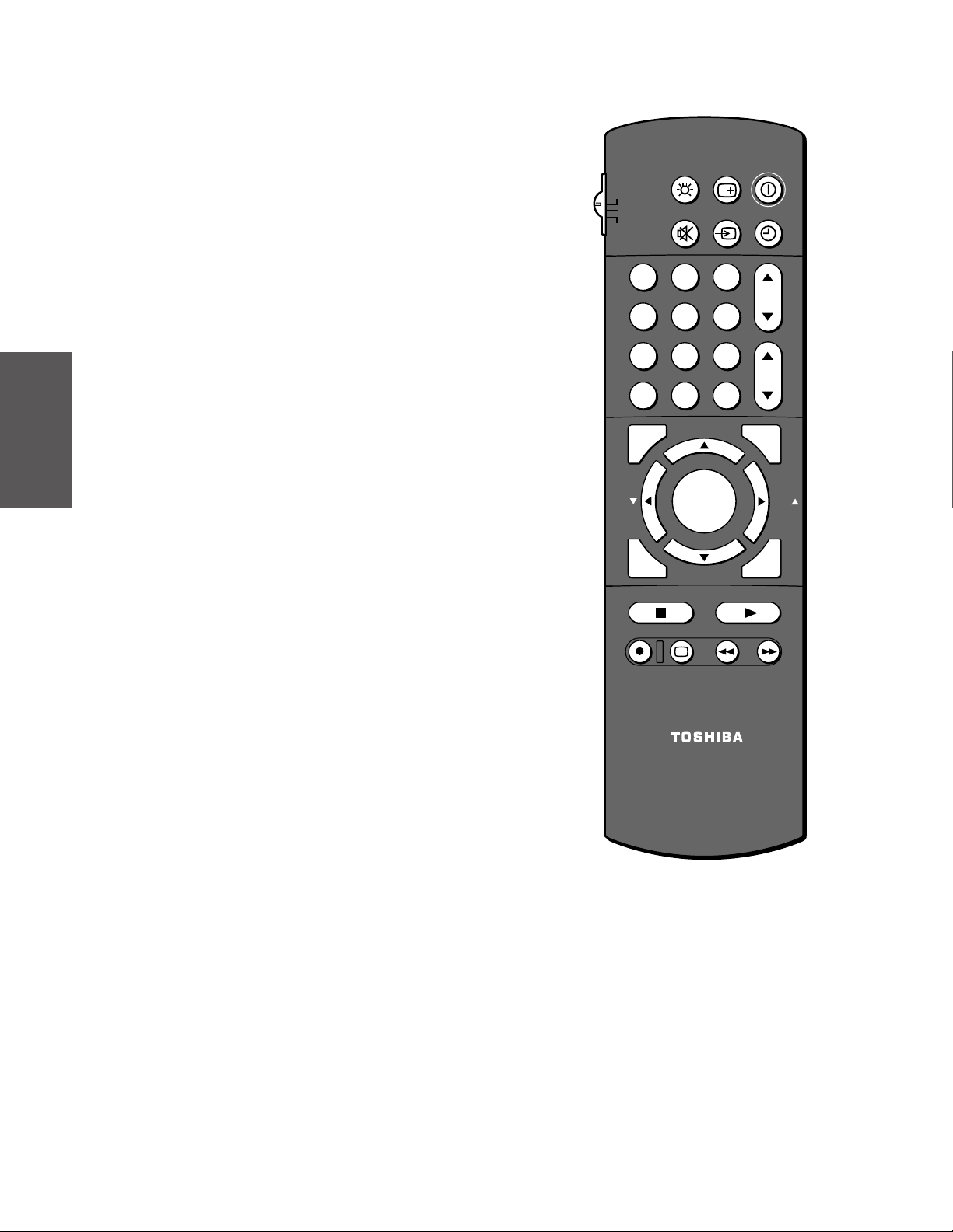
Learning about the remote control
POWER turns the TV on and off
Introduction
your TV
Connecting
Using the
RECALL displays screen information (page 45)
LIGHT illuminates the keypad for five seconds
TIMER sets the TV to turn off at a specific time (page 40)
TV/VIDEO selects video input source (pages 18, 38)
MUTE mutes the sound (page 41)
TV/CABLE/VCR switches between TV, Cable and VCR (pages 12-13)
Channel yzcycles through programmed channels (page 20)
Channel Numbers allow direct access to channels (page 20)
Volume yzadjusts the volume level
CH RTN returns to the last viewed channel (page 22)
PIC SIZE cycles through the three picture formats: Normal, Letterbox,
Remote Control
MENU allows access to on-screen programming menus (page 17)
ENTER sets programmed menu information (page 17)
yzx•select or adjust programming menus (page 17)
Setting up
your TV
PIP Channel yz
FAV zycycles through favorite channels (page 22)
FAVORITE allows access to the favorite channel search function (page 28)
and Compression (page 25)
selects the PIP (sub-picture) channel (page 26)
RECALL
LIGHT
TV
CABLE
VCR
MUTE
TV/VIDEO
123
456
789
CH RTN
100
FAV
STROBE
STOP SOURCE
REC TV/VCR REW FF
0
ADV/
PIP CH
FAVORITE
MENU/
ENTER
ADV/
PIP CH
STILL LOCATE SWAP
ENT
POWER
TIMER
CH
VOL
PIC SIZE
FAV
EXIT
PLAY PIP
Features
Using the TV’s
Appendix
Index
STROBE allows access to multi-window function (page 28)
EXIT exits programming menus (page 17)
PIP turns the PIP/double-window feature on and off (page 26)
SOURCE selects the PIP/double-window picture source (page 26)
STILL freezes the PIP/double-window picture (page 27)
LOCATE moves the small picture (page 27)
SWAP switches the main and sub pictures (page 27)
VCR Functions allow access to VCR functions (page 12)
STOP stops a videotape
REC starts recording a videotape
PLAY plays a videotape
FF fast forwards a videotape
REW rewinds a videotape
TV/VCR toggles between TV and VCR when viewing while recording
CT-90087
Note:
The error message “Not Available” will appear
if you press a key for a function that is not
available.
16
 Loading...