

Page 1

PRINTER
e-STUDIO 500P
P/N 12G9609
Page 2

Edition: June 2005
The following paragraph does not apply to any country where such provisions are inconsistent with local law:
Toshiba America Business Solutions PROVIDES THIS PUBLICATION “AS IS” WITHOUT WARRANTY OF ANY KIND,
EITHER EXPRESS OR IMPLIED, INCLUDING, BUT NOT LIMITED TO, THE IMPLIED WARRANTIES OF
MERCHANTABILITY OR FITNESS FOR A PARTICULAR PURPOSE. Some states do not allow disclaimer of express or
implied warranties in certain transactions; therefore, this statement may not apply to you.
This publication could include technical inaccuracies or typographical errors. Changes are periodically made to the
information herein; these changes will be incorporated in later editions. Improvements or changes in the products or the
programs described may be made at any time.
Comments may be addressed to Toshiba America Business Solutions, 2 Musick, Irvine, CA 92618 -- Attn Service Training.
Toshiba may use or distribute any
of the information you supply in any way it believes appropriate without incurring any
obligation to you. You can download copies of this manual from the Toshiba FYI website under Tech-To-Go.
In other countries, contact your point of purchase.
MarkNet and MarkVision are trademarks of Lexmark International, Inc..
Other trademarks are the property of their
respective owners.
© 2005 Toshiba America Business Solutions.
All rights reserved.
UNITED STATES GOVERNMENT RIGHTS
This software and any accompanying documentation provided under this agreement are commercial computer software
and documentation developed exclusively at private expense.
P/N 12G9609
Page 3

Table of contents
Laser notices . . . . . . . . . . . . . . . . . . . . . . . . . . . . . . . . . . . . . . . . . . . . . . . . . . . . . . . . . . xi
Safety information
Preface
. . . . . . . . . . . . . . . . . . . . . . . . . . . . . . . . . . . . . . . . . . . . . . . . . . . . . . . . . . . . . . xx
Definitions . . . . . . . . . . . . . . . . . . . . . . . . . . . . . . . . . . . . . . . . . . . . . . . . . . . . . . . . . . . . . . . . . . . . . . . . . . . xx
. . . . . . . . . . . . . . . . . . . . . . . . . . . . . . . . . . . . . . . . . . . . . . . . . . . . xvii
General information . . . . . . . . . . . . . . . . . . . . . . . . . . . . . . . . . . . . . . . . . . . . . . . . . . .1-1
Maintenance approach . . . . . . . . . . . . . . . . . . . . . . . . . . . . . . . . . . . . . . . . . . . . . . . . . . . . . . . . . . . . . . . 1-1
Options . . . . . . . . . . . . . . . . . . . . . . . . . . . . . . . . . . . . . . . . . . . . . . . . . . . . . . . . . . . . . . . . . . . . . . . . . . . . 1-1
Configured models . . . . . . . . . . . . . . . . . . . . . . . . . . . . . . . . . . . . . . . . . . . . . . . . . . . . . . . . . . . . . . . . 1-2
Specifications . . . . . . . . . . . . . . . . . . . . . . . . . . . . . . . . . . . . . . . . . . . . . . . . . . . . . . . . . . . . . . . . . . . . . . . 1-3
Resolution . . . . . . . . . . . . . . . . . . . . . . . . . . . . . . . . . . . . . . . . . . . . . . . . . . . . . . . . . . . . . . . . . . . . . . 1-3
Data streams . . . . . . . . . . . . . . . . . . . . . . . . . . . . . . . . . . . . . . . . . . . . . . . . . . . . . . . . . . . . . . . . . . . . 1-3
Print speed and performance print speed . . . . . . . . . . . . . . . . . . . . . . . . . . . . . . . . . . . . . . . . . . . . . . 1-3
Performance. . . . . . . . . . . . . . . . . . . . . . . . . . . . . . . . . . . . . . . . . . . . . . . . . . . . . . . . . . . . . . . . . 1-3
Time to first print . . . . . . . . . . . . . . . . . . . . . . . . . . . . . . . . . . . . . . . . . . . . . . . . . . . . . . . . . . . . . 1-3
Memory configuration . . . . . . . . . . . . . . . . . . . . . . . . . . . . . . . . . . . . . . . . . . . . . . . . . . . . . . . . . . . . . 1-4
Operating clearances . . . . . . . . . . . . . . . . . . . . . . . . . . . . . . . . . . . . . . . . . . . . . . . . . . . . . . . . . . . . . . 1-4
Dimensions . . . . . . . . . . . . . . . . . . . . . . . . . . . . . . . . . . . . . . . . . . . . . . . . . . . . . . . . . . . . . . . . . . . . . 1-5
Power requirements . . . . . . . . . . . . . . . . . . . . . . . . . . . . . . . . . . . . . . . . . . . . . . . . . . . . . . . . . . . . . . . 1-6
Electrical specifications . . . . . . . . . . . . . . . . . . . . . . . . . . . . . . . . . . . . . . . . . . . . . . . . . . . . . . . . . . . . 1-6
Environment . . . . . . . . . . . . . . . . . . . . . . . . . . . . . . . . . . . . . . . . . . . . . . . . . . . . . . . . . . . . . . . . . . . . . 1-7
Acoustics . . . . . . . . . . . . . . . . . . . . . . . . . . . . . . . . . . . . . . . . . . . . . . . . . . . . . . . . . . . . . . . . . . . . . . . 1-7
Media specifications . . . . . . . . . . . . . . . . . . . . . . . . . . . . . . . . . . . . . . . . . . . . . . . . . . . . . . . . . . . . . . . . . 1-8
Paper and specialty media guidelines . . . . . . . . . . . . . . . . . . . . . . . . . . . . . . . . . . . . . . . . . . . . . . . . . 1-8
Supported print media . . . . . . . . . . . . . . . . . . . . . . . . . . . . . . . . . . . . . . . . . . . . . . . . . . . . . . . . . . . . . 1-8
Selecting print media . . . . . . . . . . . . . . . . . . . . . . . . . . . . . . . . . . . . . . . . . . . . . . . . . . . . . . . . . . . . . 1-15
Paper . . . . . . . . . . . . . . . . . . . . . . . . . . . . . . . . . . . . . . . . . . . . . . . . . . . . . . . . . . . . . . . . . . . . . 1-15
Paper characteristics . . . . . . . . . . . . . . . . . . . . . . . . . . . . . . . . . . . . . . . . . . . . . . . . . . . . . . . . . 1-15
Weight . . . . . . . . . . . . . . . . . . . . . . . . . . . . . . . . . . . . . . . . . . . . . . . . . . . . . . . . . . . . . . . . . . . . 1-15
Unacceptable paper. . . . . . . . . . . . . . . . . . . . . . . . . . . . . . . . . . . . . . . . . . . . . . . . . . . . . . . . . . 1-15
Transparencies . . . . . . . . . . . . . . . . . . . . . . . . . . . . . . . . . . . . . . . . . . . . . . . . . . . . . . . . . . . . . 1-16
Selecting transparencies . . . . . . . . . . . . . . . . . . . . . . . . . . . . . . . . . . . . . . . . . . . . . . . . . . . . . . 1-16
Envelopes . . . . . . . . . . . . . . . . . . . . . . . . . . . . . . . . . . . . . . . . . . . . . . . . . . . . . . . . . . . . . . . . . 1-16
Labels. . . . . . . . . . . . . . . . . . . . . . . . . . . . . . . . . . . . . . . . . . . . . . . . . . . . . . . . . . . . . . . . . . . . . 1-17
Card stock . . . . . . . . . . . . . . . . . . . . . . . . . . . . . . . . . . . . . . . . . . . . . . . . . . . . . . . . . . . . . . . . . 1-18
Storing print media . . . . . . . . . . . . . . . . . . . . . . . . . . . . . . . . . . . . . . . . . . . . . . . . . . . . . . . . . . . . . . . 1-18
Avoiding jams . . . . . . . . . . . . . . . . . . . . . . . . . . . . . . . . . . . . . . . . . . . . . . . . . . . . . . . . . . . . . . . . . . 1-19
Print area . . . . . . . . . . . . . . . . . . . . . . . . . . . . . . . . . . . . . . . . . . . . . . . . . . . . . . . . . . . . . . . . . . . . . . 1-19
Tools required . . . . . . . . . . . . . . . . . . . . . . . . . . . . . . . . . . . . . . . . . . . . . . . . . . . . . . . . . . . . . . . . . . . . . 1-19
Acronyms . . . . . . . . . . . . . . . . . . . . . . . . . . . . . . . . . . . . . . . . . . . . . . . . . . . . . . . . . . . . . . . . . . . . . . . . . 1-20
Diagnostic information . . . . . . . . . . . . . . . . . . . . . . . . . . . . . . . . . . . . . . . . . . . . . . . . .2-1
Start . . . . . . . . . . . . . . . . . . . . . . . . . . . . . . . . . . . . . . . . . . . . . . . . . . . . . . . . . . . . . . . . . . . . . . . . . . . . . . . 2-1
Symptom tables . . . . . . . . . . . . . . . . . . . . . . . . . . . . . . . . . . . . . . . . . . . . . . . . . . . . . . . . . . . . . . 2-1
Service errors (9xx.xx’s). . . . . . . . . . . . . . . . . . . . . . . . . . . . . . . . . . . . . . . . . . . . . . . . . . . . . . . . 2-1
User status and attendance messages . . . . . . . . . . . . . . . . . . . . . . . . . . . . . . . . . . . . . . . . . . . . 2-1
Additional information. . . . . . . . . . . . . . . . . . . . . . . . . . . . . . . . . . . . . . . . . . . . . . . . . . . . . . . . . . 2-1
Understanding the printer operator panel . . . . . . . . . . . . . . . . . . . . . . . . . . . . . . . . . . . . . . . . . . . . . . 2-2
Understanding the menus . . . . . . . . . . . . . . . . . . . . . . . . . . . . . . . . . . . . . . . . . . . . . . . . . . . . . . . . . . 2-3
Power-On Self Test (POST) sequence . . . . . . . . . . . . . . . . . . . . . . . . . . . . . . . . . . . . . . . . . . . . . . . . . . . 2-4
Table of contents iii
Page 4

Symptom tables . . . . . . . . . . . . . . . . . . . . . . . . . . . . . . . . . . . . . . . . . . . . . . . . . . . . . . . . . . . . . . . . . . . . . .2-5
Base printer symptoms . . . . . . . . . . . . . . . . . . . . . . . . . . . . . . . . . . . . . . . . . . . . . . . . . . . . . . . . . . . . .2-5
High-capacity feeder (2000-sheet) symptoms . . . . . . . . . . . . . . . . . . . . . . . . . . . . . . . . . . . . . . . . . . .2-5
Paper tray symptoms . . . . . . . . . . . . . . . . . . . . . . . . . . . . . . . . . . . . . . . . . . . . . . . . . . . . . . . . . . . . . . 2-6
Duplex option symptoms . . . . . . . . . . . . . . . . . . . . . . . . . . . . . . . . . . . . . . . . . . . . . . . . . . . . . . . . . . . .2-6
Envelope feeder symptoms . . . . . . . . . . . . . . . . . . . . . . . . . . . . . . . . . . . . . . . . . . . . . . . . . . . . . . . . . 2-6
Output expander . . . . . . . . . . . . . . . . . . . . . . . . . . . . . . . . . . . . . . . . . . . . . . . . . . . . . . . . . . . . . . . . . . 2-6
StapleSmart finisher . . . . . . . . . . . . . . . . . . . . . . . . . . . . . . . . . . . . . . . . . . . . . . . . . . . . . . . . . . . . . . . 2-7
Messages and error codes . . . . . . . . . . . . . . . . . . . . . . . . . . . . . . . . . . . . . . . . . . . . . . . . . . . . . . . . . . . . . 2-8
Service error codes . . . . . . . . . . . . . . . . . . . . . . . . . . . . . . . . . . . . . . . . . . . . . . . . . . . . . . . . . . . . . . . .2-8
User status displays . . . . . . . . . . . . . . . . . . . . . . . . . . . . . . . . . . . . . . . . . . . . . . . . . . . . . . . . . . . . . .2-31
User attendance messages . . . . . . . . . . . . . . . . . . . . . . . . . . . . . . . . . . . . . . . . . . . . . . . . . . . . . . . .2-32
User line 2 link messages . . . . . . . . . . . . . . . . . . . . . . . . . . . . . . . . . . . . . . . . . . . . . . . . . . . . . .2-43
Check device connection messages . . . . . . . . . . . . . . . . . . . . . . . . . . . . . . . . . . . . . . . . . . . . . .2-43
User attendance messages—paper jams and paper handling errors (2xx.xx) . . . . . . . . . . . . . . . . . .2-44
Service checks . . . . . . . . . . . . . . . . . . . . . . . . . . . . . . . . . . . . . . . . . . . . . . . . . . . . . . . . . . . . . . . . . . . . . .2-72
5-Bin mailbox service check . . . . . . . . . . . . . . . . . . . . . . . . . . . . . . . . . . . . . . . . . . . . . . . . . . . . . . . .2-72
900.xx Error code service check . . . . . . . . . . . . . . . . . . . . . . . . . . . . . . . . . . . . . . . . . . . . . . . . . . . . . 2-75
927.xx Fan service check . . . . . . . . . . . . . . . . . . . . . . . . . . . . . . . . . . . . . . . . . . . . . . . . . . . . . . . . . .2-76
Main fan. . . . . . . . . . . . . . . . . . . . . . . . . . . . . . . . . . . . . . . . . . . . . . . . . . . . . . . . . . . . . . . . . . . . 2-76
Cartridge fan service check. . . . . . . . . . . . . . . . . . . . . . . . . . . . . . . . . . . . . . . . . . . . . . . . . . . . . 2-76
950.00 through 950.29 EPROM mismatch failure . . . . . . . . . . . . . . . . . . . . . . . . . . . . . . . . . . . . . . .2-77
950.30 through 950.60 EPROM mismatch failure . . . . . . . . . . . . . . . . . . . . . . . . . . . . . . . . . . . . . . .2-78
Charge roll service check . . . . . . . . . . . . . . . . . . . . . . . . . . . . . . . . . . . . . . . . . . . . . . . . . . . . . . . . . .2-79
Cover closed switch/cable service check . . . . . . . . . . . . . . . . . . . . . . . . . . . . . . . . . . . . . . . . . . . . . . 2-80
Dead machine service check . . . . . . . . . . . . . . . . . . . . . . . . . . . . . . . . . . . . . . . . . . . . . . . . . . . . . . . 2-80
Duplex option service check . . . . . . . . . . . . . . . . . . . . . . . . . . . . . . . . . . . . . . . . . . . . . . . . . . . . . . . .2-82
Envelope feeder service check . . . . . . . . . . . . . . . . . . . . . . . . . . . . . . . . . . . . . . . . . . . . . . . . . . . . . . 2-84
Fuser service checks . . . . . . . . . . . . . . . . . . . . . . . . . . . . . . . . . . . . . . . . . . . . . . . . . . . . . . . . . . . . .2-87
920.xx—Cold fuser service check. . . . . . . . . . . . . . . . . . . . . . . . . . . . . . . . . . . . . . . . . . . . . . . . 2-87
922.xx—Cold fuser check . . . . . . . . . . . . . . . . . . . . . . . . . . . . . . . . . . . . . . . . . . . . . . . . . . . . . . 2-89
923.xx—Hot fuser service check. . . . . . . . . . . . . . . . . . . . . . . . . . . . . . . . . . . . . . . . . . . . . . . . .2-90
924.xx—Hot fuser service check. . . . . . . . . . . . . . . . . . . . . . . . . . . . . . . . . . . . . . . . . . . . . . . . .2-91
925.xx—Hot fuser service check. . . . . . . . . . . . . . . . . . . . . . . . . . . . . . . . . . . . . . . . . . . . . . . . .2-91
Fuser exit sensor service check . . . . . . . . . . . . . . . . . . . . . . . . . . . . . . . . . . . . . . . . . . . . . . . . . . . . .2-92
Fuser narrow media sensor service check . . . . . . . . . . . . . . . . . . . . . . . . . . . . . . . . . . . . . . . . . . . . .2-93
Fuser solenoid service check . . . . . . . . . . . . . . . . . . . . . . . . . . . . . . . . . . . . . . . . . . . . . . . . . . . . . . .2-94
High-capacity feeder input tray service check . . . . . . . . . . . . . . . . . . . . . . . . . . . . . . . . . . . . . . . . . .2-95
High-capacity output stacker service check . . . . . . . . . . . . . . . . . . . . . . . . . . . . . . . . . . . . . . . . . . .2-100
Input sensor service check . . . . . . . . . . . . . . . . . . . . . . . . . . . . . . . . . . . . . . . . . . . . . . . . . . . . . . . .2-102
Input tray(s) service check . . . . . . . . . . . . . . . . . . . . . . . . . . . . . . . . . . . . . . . . . . . . . . . . . . . . . . . .2-102
Interconnect card service check . . . . . . . . . . . . . . . . . . . . . . . . . . . . . . . . . . . . . . . . . . . . . . . . . . . . 2-104
Main drive service check . . . . . . . . . . . . . . . . . . . . . . . . . . . . . . . . . . . . . . . . . . . . . . . . . . . . . . . . . .2-105
Operator panel service check . . . . . . . . . . . . . . . . . . . . . . . . . . . . . . . . . . . . . . . . . . . . . . . . . . . . . . 2-106
One or more operator panel buttons fail . . . . . . . . . . . . . . . . . . . . . . . . . . . . . . . . . . . . . . . . . .2-106
No buttons work . . . . . . . . . . . . . . . . . . . . . . . . . . . . . . . . . . . . . . . . . . . . . . . . . . . . . . . . . . . .2-106
Operator panel display . . . . . . . . . . . . . . . . . . . . . . . . . . . . . . . . . . . . . . . . . . . . . . . . . . . . . . . 2-107
Options service check . . . . . . . . . . . . . . . . . . . . . . . . . . . . . . . . . . . . . . . . . . . . . . . . . . . . .
Flash Memory Option(s) . . . . . . . . . . . . . . . . . . . . . . . . . . . . . . . . . . . . . . . . . . . . . . . . . . . . . .2-108
DRAM Memory Option(s) . . . . . . . . . . . . . . . . . . . . . . . . . . . . . . . . . . . . . . . . . . . . . . . . . . . . .2-108
Hard Disk Option . . . . . . . . . . . . . . . . . . . . . . . . . . . . . . . . . . . . . . . . . . . . . . . . . . . . . . . . . . . .2-108
Output bin sensor standard tray service check . . . . . . . . . . . . . . . . . . . . . . . . . . . . . . . . . . . . . . . . .2-109
Output expander service check . . . . . . . . . . . . . . . . . . . . . . . . . . . . . . . . . . . . . . . . . . . . . . . . . . . .2-110
Paper feed service check . . . . . . . . . . . . . . . . . . . . . . . . . . . . . . . . . . . . . . . . . . . . . . . . . . . . . . . . .2-112
Paper size sensing service check . . . . . . . . . . . . . . . . . . . . . . . . . . . . . . . . . . . . . . . . . . . . . . . . . . .2-113
Parallel port service check . . . . . . . . . . . . . . . . . . . . . . . . . . . . . . . . . . . . . . . . . . . . . . . . . . . . . . . .2-116
Print quality service check . . . . . . . . . . . . . . . . . . . . . . . . . . . . . . . . . . . . . . . . . . . . . . . . . . . . . . . .2-116
Printhead service check . . . . . . . . . . . . . . . . . . . . . . . . . . . . . . . . . . . . . . . . . . . . . . . . . . . . . . . . . .2-122
. . . . . . .2-108
iv Service Manual
Page 5

Signature button assembly service check . . . . . . . . . . . . . . . . . . . . . . . . . . . . . . . . . . . . . . . . . . . . 2-122
StapleSmart finisher service check . . . . . . . . . . . . . . . . . . . . . . . . . . . . . . . . . . . . . . . . . . . . . . . . . 2-123
System board service check . . . . . . . . . . . . . . . . . . . . . . . . . . . . . . . . . . . . . . . . . . . . . . . . . . . . . . 2-126
Toner sensor service check . . . . . . . . . . . . . . . . . . . . . . . . . . . . . . . . . . . . . . . . . . . . . . . . . . . . . . . 2-127
Transfer roll service check . . . . . . . . . . . . . . . . . . . . . . . . . . . . . . . . . . . . . . . . . . . . . . . . . . . . . . . . 2-128
Diagnostic aids . . . . . . . . . . . . . . . . . . . . . . . . . . . . . . . . . . . . . . . . . . . . . . . . . . . . . . .3-1
Accessing service menus . . . . . . . . . . . . . . . . . . . . . . . . . . . . . . . . . . . . . . . . . . . . . . . . . . . . . . . . . . . . . 3-1
Diagnostics mode . . . . . . . . . . . . . . . . . . . . . . . . . . . . . . . . . . . . . . . . . . . . . . . . . . . . . . . . . . . . . . . . . . . 3-2
Entering Diagnostics mode . . . . . . . . . . . . . . . . . . . . . . . . . . . . . . . . . . . . . . . . . . . . . . . . . . . . . . . . . 3-2
Available tests . . . . . . . . . . . . . . . . . . . . . . . . . . . . . . . . . . . . . . . . . . . . . . . . . . . . . . . . . . . . . . . . . . . 3-2
Exiting Diagnostics mode . . . . . . . . . . . . . . . . . . . . . . . . . . . . . . . . . . . . . . . . . . . . . . . . . . . . . . . . . . 3-4
REGISTRATION . . . . . . . . . . . . . . . . . . . . . . . . . . . . . . . . . . . . . . . . . . . . . . . . . . . . . . . . . . . . . . . . . 3-4
Quick Test . . . . . . . . . . . . . . . . . . . . . . . . . . . . . . . . . . . . . . . . . . . . . . . . . . . . . . . . . . . . . . . . . . 3-5
PRINT TESTS . . . . . . . . . . . . . . . . . . . . . . . . . . . . . . . . . . . . . . . . . . . . . . . . . . . . . . . . . . . . . . . . . . . 3-6
Input source tests. . . . . . . . . . . . . . . . . . . . . . . . . . . . . . . . . . . . . . . . . . . . . . . . . . . . . . . . . . . . . 3-6
Print quality pages (Prt Quality Pgs) . . . . . . . . . . . . . . . . . . . . . . . . . . . . . . . . . . . . . . . . . . . . . . 3-6
HARDWARE TESTS . . . . . . . . . . . . . . . . . . . . . . . . . . . . . . . . . . . . . . . . . . . . . . . . . . . . . . . . . . . . . . 3-7
Panel Test . . . . . . . . . . . . . . . . . . . . . . . . . . . . . . . . . . . . . . . . . . . . . . . . . . . . . . . . . . . . . . . . . . 3-7
Button Test. . . . . . . . . . . . . . . . . . . . . . . . . . . . . . . . . . . . . . . . . . . . . . . . . . . . . . . . . . . . . . . . . . 3-7
DRAM Test. . . . . . . . . . . . . . . . . . . . . . . . . . . . . . . . . . . . . . . . . . . . . . . . . . . . . . . . . . . . . . . . . . 3-7
CACHE Test. . . . . . . . . . . . . . . . . . . . . . . . . . . . . . . . . . . . . . . . . . . . . . . . . . . . . . . . . . . . . . . . . 3-8
Parallel Wrap tests . . . . . . . . . . . . . . . . . . . . . . . . . . . . . . . . . . . . . . . . . . . . . . . . . . . . . . . . . . . . 3-8
Serial Wrap tests . . . . . . . . . . . . . . . . . . . . . . . . . . . . . . . . . . . . . . . . . . . . . . . . . . . . . . . . . . . . . 3-9
DUPLEX TESTS . . . . . . . . . . . . . . . . . . . . . . . . . . . . . . . . . . . . . . . . . . . . . . . . . . . . . . . . . . . . . . . . . 3-9
Quick Test (duplex) . . . . . . . . . . . . . . . . . . . . . . . . . . . . . . . . . . . . . . . . . . . . . . . . . . . . . . . . . . . 3-9
Top Margin (duplex). . . . . . . . . . . . . . . . . . . . . . . . . . . . . . . . . . . . . . . . . . . . . . . . . . . . . . . . . . 3-10
Sensor Test (duplex) . . . . . . . . . . . . . . . . . . . . . . . . . . . . . . . . . . . . . . . . . . . . . . . . . . . . . . . . . 3-10
Motor Test (duplex) . . . . . . . . . . . . . . . . . . . . . . . . . . . . . . . . . . . . . . . . . . . . . . . . . . . . . . . . . . 3-11
Duplex Feed 1 . . . . . . . . . . . . . . . . . . . . . . . . . . . . . . . . . . . . . . . . . . . . . . . . . . . . . . . . . . . . . . 3-12
Duplex Feed 2 . . . . . . . . . . . . . . . . . . . . . . . . . . . . . . . . . . . . . . . . . . . . . . . . . . . . . . . . . . . . . . 3-12
INPUT TRAY TESTS . . . . . . . . . . . . . . . . . . . . . . . . . . . . . . . . . . . . . . . . . . . . . . . . . . . . . . . . . . . . . 3-13
Feed Tests (input tray). . . . . . . . . . . . . . . . . . . . . . . . . . . . . . . . . . . . . . . . . . . . . . . . . . . . . . . . 3-13
Sensor Test (input tray) . . . . . . . . . . . . . . . . . . . . . . . . . . . . . . . . . . . . . . . . . . . . . . . . . . . . . . . 3-13
OUTPUT BIN TESTS . . . . . . . . . . . . . . . . . . . . . . . . . . . . . . . . . . . . . . . . . . . . . . . . . . . . . . . . . . . . 3-14
Feed Tests (output bins) . . . . . . . . . . . . . . . . . . . . . . . . . . . . . . . . . . . . . . . . . . . . . . . . . . . . . . 3-14
Feed To All Bins. . . . . . . . . . . . . . . . . . . . . . . . . . . . . . . . . . . . . . . . . . . . . . . . . . . . . . . . . . . . . 3-14
The test is continuous until Stop () is pressed. . . . . . . . . . . . . . . . . . . . . . . . . . . . . . . . . . . . . . 3-14
Sensor Test (standard output bin) . . . . . . . . . . . . . . . . . . . . . . . . . . . . . . . . . . . . . . . . . . . . . . . 3-15
Sensor Test (Output Expander) . . . . . . . . . . . . . . . . . . . . . . . . . . . . . . . . . . . . . . . . . . . . . . . . . 3-15
Sensor Test (high capacity output stacker) . . . . . . . . . . . . . . . . . . . . . . . . . . . . . . . . . . . . . . . . 3-16
Sensor Tests (5-bin mailbox) . . . . . . . . . . . . . . . . . . . . . . . . . . . . . . . . . . . . . . . . . . . . . . . . . . . 3-16
Diverter Test. . . . . . . . . . . . . . . . . . . . . . . . . . . . . . . . . . . . . . . . . . . . . . . . . . . . . . . . . . . . . . . . 3-16
FINISHER TESTS . . . . . . . . . . . . . . . . . . . . . . . . . . . . . . . . . . . . . . . . . . . . . . . . . . . . . . . . . . . . . . . 3-17
Staple Test . . . . . . . . . . . . . . . . . . . . . . . . . . . . . . . . . . . . . . . . . . . . . . . . . . . . . . . . . . . . . . . . . 3-17
Feed Tests (finisher) . . . . . . . . . . . . . . . . . . . . . . . . . . . . . . . . . . . . . . . . . . . . . . . . . . . . . . . . . 3-17
Sensor Test (finisher). . . . . . . . . . . . . . . . . . . . . . . . . . . . . . . . . . . . . . . . . . . . . . . . . . . . . . . . . 3-17
BASE SENSOR TEST . . . . . . . . . . . . . . . . . . . . . . . . . . . . . . . . . . . . . . . . . . . . . . . . . . . . . . . . . . . . 3-18
DEVICE TESTS . . . . . . . . . . . . . . . . . . . . . . . . . . . . . . . . . . . . . . . . . . . . . . . . . . . . . . . . . . . . . . . . . 3-18
Quick Disk Test . . . . . . . . . . . . . . . . . . . . . . . . . . . . . . . . . . . . . . . . . . . . . . . . . . . . . . . . . . . . . 3-18
Disk Test/Clean . . . . . . . . . . . . . . . . . . . . . . . . . . . . . . . . . . . . . . . . . . . . . . . . . . . . . . . . . . . . . 3-19
Flash Test . . . . . . . . . . . . . . . . . . . . . . . . . . . . . . . . . . . . . . . . . . . . . . . . . . . . . . . . . . . . . . . . . 3-19
PRINTER SETUP . . . . . . . . . . . . . . . . . . . . . . . . . . . . . . . . . . . . . . . . . . . . . . . . . . . . . . . . . . . . . . . 3-20
Defaults . . . . . . . . . . . . . . . . . . . . . . . . . . . . . . . . . . . . . . . . . . . . . . . . . . . . . . . . . . . . . . . . . . . 3-20
Page Count . . . . . . . . . . . . . . . . . . . . . . . . . . . . . . . . . . . . . . . . . . . . . . . . . . . . . . . . . . . . . . . . 3-20
Perm Page Count (permanent page count) . . . . . . . . . . . . . . . . . . . . . . . . . . . . . . . . . . . . . . . . 3-20
Serial Number . . . . . . . . . . . . . . . . . . . . . . . . . . . . . . . . . . . . . . . . . . . . . . . . . . . . . . . . . . . . . . 3-20
Envelope Enhance. . . . . . . . . . . . . . . . . . . . . . . . . . . . . . . . . . . . . . . . . . . . . . . . . . . . . . . . . . . 3-20
Table of contents v
Page 6

Engine Setting 1 through 4 . . . . . . . . . . . . . . . . . . . . . . . . . . . . . . . . . . . . . . . . . . . . . . . . . . . . . 3-20
Model Name . . . . . . . . . . . . . . . . . . . . . . . . . . . . . . . . . . . . . . . . . . . . . . . . . . . . . . . . . . . . . . . .3-20
Configuration ID . . . . . . . . . . . . . . . . . . . . . . . . . . . . . . . . . . . . . . . . . . . . . . . . . . . . . . . . . . . . .3-21
Edge to Edge. . . . . . . . . . . . . . . . . . . . . . . . . . . . . . . . . . . . . . . . . . . . . . . . . . . . . . . . . . . . . . . .3-21
Parallel strobe adjustment (Par x Strobe Adj). . . . . . . . . . . . . . . . . . . . . . . . . . . . . . . . . . . . . . .3-21
EP SETUP . . . . . . . . . . . . . . . . . . . . . . . . . . . . . . . . . . . . . . . . . . . . . . . . . . . . . . . . . . . . . . . . . . . . . 3-22
EP Defaults . . . . . . . . . . . . . . . . . . . . . . . . . . . . . . . . . . . . . . . . . . . . . . . . . . . . . . . . . . . . . . . . .3-22
Fuser Temperature (Fuser Temp) . . . . . . . . . . . . . . . . . . . . . . . . . . . . . . . . . . . . . . . . . . . . . . . . 3-22
Fuser Page Count . . . . . . . . . . . . . . . . . . . . . . . . . . . . . . . . . . . . . . . . . . . . . . . . . . . . . . . . . . . . 3-22
Warm Up Time . . . . . . . . . . . . . . . . . . . . . . . . . . . . . . . . . . . . . . . . . . . . . . . . . . . . . . . . . . . . . .3-22
Transfer . . . . . . . . . . . . . . . . . . . . . . . . . . . . . . . . . . . . . . . . . . . . . . . . . . . . . . . . . . . . . . . . . . . .3-22
Print Contrast . . . . . . . . . . . . . . . . . . . . . . . . . . . . . . . . . . . . . . . . . . . . . . . . . . . . . . . . . . . . . . .3-22
Charge Roll . . . . . . . . . . . . . . . . . . . . . . . . . . . . . . . . . . . . . . . . . . . . . . . . . . . . . . . . . . . . . . . . .3-22
Gap Adjust. . . . . . . . . . . . . . . . . . . . . . . . . . . . . . . . . . . . . . . . . . . . . . . . . . . . . . . . . . . . . . . . . .3-22
EVENT LOG . . . . . . . . . . . . . . . . . . . . . . . . . . . . . . . . . . . . . . . . . . . . . . . . . . . . . . . . . . . . . . . . . . . . 3-23
Display Log . . . . . . . . . . . . . . . . . . . . . . . . . . . . . . . . . . . . . . . . . . . . . . . . . . . . . . . . . . . . . . . . .3-23
Print Log . . . . . . . . . . . . . . . . . . . . . . . . . . . . . . . . . . . . . . . . . . . . . . . . . . . . . . . . . . . . . . . . . . .3-23
Clear Log. . . . . . . . . . . . . . . . . . . . . . . . . . . . . . . . . . . . . . . . . . . . . . . . . . . . . . . . . . . . . . . . . . .3-24
EXIT DIAGNOSTICS . . . . . . . . . . . . . . . . . . . . . . . . . . . . . . . . . . . . . . . . . . . . . . . . . . . . . . . . . . . . .3-24
Configuration menu (CONFIG MENU) . . . . . . . . . . . . . . . . . . . . . . . . . . . . . . . . . . . . . . . . . . . . . . . . . . .3-25
Entering Configuration Menu . . . . . . . . . . . . . . . . . . . . . . . . . . . . . . . . . . . . . . . . . . . . . . . . . . . . . . .3-25
Available menus . . . . . . . . . . . . . . . . . . . . . . . . . . . . . . . . . . . . . . . . . . . . . . . . . . . . . . . . . . . . . . . . .3-25
Maintenance page count (Maint Cnt Value) . . . . . . . . . . . . . . . . . . . . . . . . . . . . . . . . . . . . . . . . . . . .3-25
Maintenance page counter reset (Reset Maint Cnt) . . . . . . . . . . . . . . . . . . . . . . . . . . . . . . . . . . . . . .3-26
Print quality pages (Prt Quality Pgs) . . . . . . . . . . . . . . . . . . . . . . . . . . . . . . . . . . . . . . . . . . . . . . . . . . 3-26
SIZE SENSING . . . . . . . . . . . . . . . . . . . . . . . . . . . . . . . . . . . . . . . . . . . . . . . . . . . . . . . . . . . . . . . . . .3-27
Panel Menus . . . . . . . . . . . . . . . . . . . . . . . . . . . . . . . . . . . . . . . . . . . . . . . . . . . . . . . . . . . . . . . . . . . .3-27
PPDS Emulation . . . . . . . . . . . . . . . . . . . . . . . . . . . . . . . . . . . . . . . . . . . . . . . . . . . . . . . . . . . . . . . . .3-27
Download Emuls . . . . . . . . . . . . . . . . . . . . . . . . . . . . . . . . . . . . . . . . . . . . . . . . . . . . . . . . . . . . . . . . . 3-27
Demo Mode . . . . . . . . . . . . . . . . . . . . . . . . . . . . . . . . . . . . . . . . . . . . . . . . . . . . . . . . . . . . . . . . . . . . 3-27
Factory Defaults . . . . . . . . . . . . . . . . . . . . . . . . . . . . . . . . . . . . . . . . . . . . . . . . . . . . . . . . . . . . . . . . .3-28
Energy Conserve . . . . . . . . . . . . . . . . . . . . . . . . . . . . . . . . . . . . . . . . . . . . . . . . . . . . . . . . . . . . . . . .3-28
EVENT LOG . . . . . . . . . . . . . . . . . . . . . . . . . . . . . . . . . . . . . . . . . . . . . . . . . . . . . . . . . . . . . . . . . . . . 3-28
Paper Prompts . . . . . . . . . . . . . . . . . . . . . . . . . . . . . . . . . . . . . . . . . . . . . . . . . . . . . . . . . . . . . . . . . .3-28
Env Prompts . . . . . . . . . . . . . . . . . . . . . . . . . . . . . . . . . . . . . . . . . . . . . . . . . . . . . . . . . . . . . . . . . . . .3-28
Jobs On Disk . . . . . . . . . . . . . . . . . . . . . . . . . . . . . . . . . . . . . . . . . . . . . . . . . . . . . . . . . . . . . . . . . . . .3-28
Disk Encryption . . . . . . . . . . . . . . . . . . . . . . . . . . . . . . . . . . . . . . . . . . . . . . . . . . . . . . . . . . . . . . . . . . 3-28
Font Sharpening . . . . . . . . . . . . . . . . . . . . . . . . . . . . . . . . . . . . . . . . . . . . . . . . . . . . . . . . . . . . . . . . . 3-29
LCD Brightness . . . . . . . . . . . . . . . . . . . . . . . . . . . . . . . . . . . . . . . . . . . . . . . . . . . . . . . . . . . . . . . . . .3-29
LCD Contrast . . . . . . . . . . . . . . . . . . . . . . . . . . . . . . . . . . . . . . . . . . . . . . . . . . . . . . . . . . . . . . . . . . . 3-29
Exit Config Menu . . . . . . . . . . . . . . . . . . . . . . . . . . . . . . . . . . . . . . . . . . . . . . . . . . . . . . . . . . . . . . . . .3-29
Additional useful menu locations . . . . . . . . . . . . . . . . . . . . . . . . . . . . . . . . . . . . . . . . . . . . . . . . . . . . . .3-29
Hex Trace . . . . . . . . . . . . . . . . . . . . . . . . . . . . . . . . . . . . . . . . . . . . . . . . . . . . . . . . . . . . . . . . . . . . . .3-29
Menu settings page . . . . . . . . . . . . . . . . . . . . . . . . . . . . . . . . . . . . . . . . . . . . . . . . . . . . . . . . . . . . . . .3-30
Printing menu settings page . . . . . . . . . . . . . . . . . . . . . . . . . . . . . . . . . . . . . . . . . . . . . . . . . . . . . . . .3-30
Theory . . . . . . . . . . . . . . . . . . . . . . . . . . . . . . . . . . . . . . . . . . . . . . . . . . . . . . . . . . . . . . . . . . . . . . . . . . . . .3-31
Autocompensator operation . . . . . . . . . . . . . . . . . . . . . . . . . . . . . . . . . . . . . . . . . . . . . . . . . . . . . . . . 3-31
Autoconnect system, paper tray options, envelope feeder—electrical . . . . . . . . . . . . . . . . . . . . . . . . 3-32
Autoconnect cabling and connectors . . . . . . . . . . . . . . . . . . . . . . . . . . . . . . . . . . . . . . . . . . . . .3-32
Duplex Option . . . . . . . . . . . . . . . . . . . . . . . . . . . . . . . . . . . . . . . . . . . . . . . . . . . . . . . . . . . . . . . 3-32
Option microcode . . . . . . . . . . . . . . . . . . . . . . . . . . . . . . . . . . . . . . . . . . . . . . . . . . . . . . . . . . . .3-32
Paper feed jams . . . . . . . . . . . . . . . . . . . . . . . . . . . . . . . . . . . . . . . . . . . . . . . . . . . . . . . . . . . . . . . . . . . . .3-33
Access doors and trays . . . . . . . . . . . . . . . . . . . . . . . . . . . . . . . . . . . . . . . . . . . . . . . . . . . . . . . . . . . .3-33
Clearing printer jams . . . . . . . . . . . . . . . . . . . . . . . . . . . . . . . . . . . . . . . . . . . . . . . . . . . . . . . . . . . . . .3-33
250 Paper Jam Check MP Feeder . . . . . . . . . . . . . . . . . . . . . . . . . . . . . . . . . . . . . . . . . . . . . . .3-34
260 Paper Jam Check Env Feeder. . . . . . . . . . . . . . . . . . . . . . . . . . . . . . . . . . . . . . . . . . . . . . .3-35
23x and 24x jams . . . . . . . . . . . . . . . . . . . . . . . . . . . . . . . . . . . . . . . . . . . . . . . . . . . . . . . . . . . .3-36
200 and 201 Paper Jam Remove Cartridge . . . . . . . . . . . . . . . . . . . . . . . . . . . . . . . . . . . . . . . . 3-37
vi Service Manual
Page 7

202 Paper Jam Open Rear Door . . . . . . . . . . . . . . . . . . . . . . . . . . . . . . . . . . . . . . . . . . . . . . . . 3-39
23x Paper Jam Open Duplex Rear Door . . . . . . . . . . . . . . . . . . . . . . . . . . . . . . . . . . . . . . . . . . 3-40
270 and 280 Paper Jams. . . . . . . . . . . . . . . . . . . . . . . . . . . . . . . . . . . . . . . . . . . . . . . . . . . . . . 3-41
27x Paper Jam Check Bin x . . . . . . . . . . . . . . . . . . . . . . . . . . . . . . . . . . . . . . . . . . . . . . . . . . . . 3-41
28x Paper Jam Check Finisher . . . . . . . . . . . . . . . . . . . . . . . . . . . . . . . . . . . . . . . . . . . . . . . . . 3-42
Repair information . . . . . . . . . . . . . . . . . . . . . . . . . . . . . . . . . . . . . . . . . . . . . . . . . . . .4-1
Handling ESD-sensitive parts . . . . . . . . . . . . . . . . . . . . . . . . . . . . . . . . . . . . . . . . . . . . . . . . . . . . . . . . . . 4-1
Adjustment procedures . . . . . . . . . . . . . . . . . . . . . . . . . . . . . . . . . . . . . . . . . . . . . . . . . . . . . . . . . . . . . . . 4-2
Fuser solenoid adjustment . . . . . . . . . . . . . . . . . . . . . . . . . . . . . . . . . . . . . . . . . . . . . . . . . . . . . . . . . . 4-2
Gap adjustment . . . . . . . . . . . . . . . . . . . . . . . . . . . . . . . . . . . . . . . . . . . . . . . . . . . . . . . . . . . . . . . . . . 4-2
Printhead assembly adjustment . . . . . . . . . . . . . . . . . . . . . . . . . . . . . . . . . . . . . . . . . . . . . . . . . . . . . . 4-2
Paper alignment assembly adjustment . . . . . . . . . . . . . . . . . . . . . . . . . . . . . . . . . . . . . . . . . . . . . . . . 4-3
Removal procedures . . . . . . . . . . . . . . . . . . . . . . . . . . . . . . . . . . . . . . . . . . . . . . . . . . . . . . . . . . . . . . . . . 4-4
Covers removals . . . . . . . . . . . . . . . . . . . . . . . . . . . . . . . . . . . . . . . . . . . . . . . . . . . . . . . . . . . . . . . . . 4-4
Fuser wiper cover assembly removal. . . . . . . . . . . . . . . . . . . . . . . . . . . . . . . . . . . . . . . . . . . . . . 4-4
Redrive cap cover removal . . . . . . . . . . . . . . . . . . . . . . . . . . . . . . . . . . . . . . . . . . . . . . . . . . . . . 4-5
Paper support removal. . . . . . . . . . . . . . . . . . . . . . . . . . . . . . . . . . . . . . . . . . . . . . . . . . . . . . . . . 4-5
Left door removal . . . . . . . . . . . . . . . . . . . . . . . . . . . . . . . . . . . . . . . . . . . . . . . . . . . . . . . . . . . . . 4-6
Redrive door. . . . . . . . . . . . . . . . . . . . . . . . . . . . . . . . . . . . . . . . . . . . . . . . . . . . . . . . . . . . . . . . . 4-7
Right cover removal . . . . . . . . . . . . . . . . . . . . . . . . . . . . . . . . . . . . . . . . . . . . . . . . . . . . . . . . . . . 4-8
Upper front cover removal . . . . . . . . . . . . . . . . . . . . . . . . . . . . . . . . . . . . . . . . . . . . . . . . . . . . . 4-11
Upper front cover latch removal . . . . . . . . . . . . . . . . . . . . . . . . . . . . . . . . . . . . . . . . . . . . . . . . . 4-13
Upper front cover outer bezel removal . . . . . . . . . . . . . . . . . . . . . . . . . . . . . . . . . . . . . . . . . . . . 4-14
Multipurpose feeder/lower front cover assembly removal . . . . . . . . . . . . . . . . . . . . . . . . . . . . . 4-15
Left cover handle holder removal. . . . . . . . . . . . . . . . . . . . . . . . . . . . . . . . . . . . . . . . . . . . . . . . 4-16
Right cover handle holder removal . . . . . . . . . . . . . . . . . . . . . . . . . . . . . . . . . . . . . . . . . . . . . . 4-16
Left and right frame extensions . . . . . . . . . . . . . . . . . . . . . . . . . . . . . . . . . . . . . . . . . . . . . . . . . 4-17
Pass thru plate . . . . . . . . . . . . . . . . . . . . . . . . . . . . . . . . . . . . . . . . . . . . . . . . . . . . . . . . . . . . . . 4-18
Laser cover removal. . . . . . . . . . . . . . . . . . . . . . . . . . . . . . . . . . . . . . . . . . . . . . . . . . . . . . . . . . 4-19
Bevel gear removal . . . . . . . . . . . . . . . . . . . . . . . . . . . . . . . . . . . . . . . . . . . . . . . . . . . . . . . . . . . . . . 4-21
Cartridge duct removal . . . . . . . . . . . . . . . . . . . . . . . . . . . . . . . . . . . . . . . . . . . . . . . . . . . . . . . . . . . 4-23
Developer drive assembly removal . . . . . . . . . . . . . . . . . . . . . . . . . . . . . . . . . . . . . . . . . . . . . . . . . . 4-24
Developer drive coupler kit removal . . . . . . . . . . . . . . . . . . . . . . . . . . . . . . . . . . . . . . . . . . . . . . . . . 4-25
ESD cover removal . . . . . . . . . . . . . . . . . . . . . . . . . . . . . . . . . . . . . . . . . . . . . . . . . . . . . . . . . . . . . . 4-25
Fuser assembly removal . . . . . . . . . . . . . . . . . . . . . . . . . . . . . . . . . . . . . . . . . . . . . . . . . . . . . . . . . . 4-26
Fuser exit sensor removal . . . . . . . . . . . . . . . . . . . . . . . . . . . . . . . . . . . . . . . . . . . . . . . . . . . . . . . . . 4-28
Fuser exit sensor flag and spring removal . . . . . . . . . . . . . . . . . . . . . . . . . . . . . . . . . . . . . . . . . . . . . 4-30
Fuser lamp removal . . . . . . . . . . . . . . . . . . . . . . . . . . . . . . . . . . . . . . . . . . . . . . . . . . . . . . . . . . . . . . 4-32
Fuser narrow media sensor removal . . . . . . . . . . . . . . . . . . . . . . . . . . . . . . . . . . . . . . . . . . . . . . . . . 4-34
Fuser narrow media flag and spring removal . . . . . . . . . . . . . . . . . . . . . . . . . . . . . . . . . . . . . . . . . . 4-36
Fuser to LVPS AC cable removal . . . . . . . . . . . . . . . . . . . . . . . . . . . . . . . . . . . . . . . . . . . . . . . . . . . 4-38
Fuser top cover removal . . . . . . . . . . . . . . . . . . . . . . . . . . . . . . . . . . . . . . . . . . . . . . . . . . . . . . . . . . 4-41
Fuser transfer plate removal . . . . . . . . . . . . . . . . . . . . . . . . . . . . . . . . . . . . . . . . . . . . . . . . . . . . . . . 4-43
Gear release link removal . . . . . . . . . . . . . . . . . . . . . . . . . . . . . . . . . . . . . . . . . . . . . . . . . . . . . . . . . 4-44
High voltage power supply removal . . . . . . . . . . . . . . . . . . . . . . . . . . . . . . . . . . . . . . . . . . . . . . . . . . 4-45
Inner paper deflector assembly removal . . . . . . . . . . . . . . . . . . . . . . . . . . . . . . . . . . . . . . . . . . . . . . 4-47
Input sensor removal . . . . . . . . . . . . . . . . . . . . . . . . . . . . . . . . . . . . . . . . . . . . . . . . . . . . . . . . . . . . . 4-48
Integrated tray autocompensator assembly removal . . . . . . . . . . . . . . . . . . . . . . . . . . . . . . . . . . . . . 4-49
Integrated tray autocompensator pick roll assembly removal . . . . . . . . . . . . . . . . . . . . . . . . . . . . . . 4-51
Interconnect card assembly removal . . . . . . . . . . . . . . . . . . . . . . . . . . . . . . . . . . . . . . . . . . . . . . . . . 4-53
Low voltage power supply removal . . . . . . . . . . . . . . . . . . . . . . . . . . . . . . . . . . . . . . . . . . . . . . . . . . 4-54
Main fan removal . . . . . . . . . . . . . . . . . . . . . . . . . . . . . . . . . . . . . . . . . . . . . . . . . . . . . . . . . . . . . . . . 4-56
Main drive assembly removal . . . . . . . . . . . . . . . . . . . . . . . . . . . . . . . . . . . . . . . . . . . . . . . . . . . . . . 4-57
MPF arm assembly removal . . . . . . . . . . . . . . . . . . . . . . . . . . . . . . . . . . . . . . . . . . . . . . . . . . . . . . . 4-60
MPF lower paper deflector . . . . . . . . . . . . . . . . . . . . . . . . . . . . . . . . . . . . . . . . . . . . . . . . . . . . . . . . . 4-61
MPF pick tire removal . . . . . . . . . . . . . . . . . . . . . . . . . . . . . . . . . . . . . . . . . . . . . . . . . . . . . . . . . . . . 4-62
MPF solenoid assembly removal . . . . . . . . . . . . . . . . . . . . . . . . . . . . . . . . . . . . . . . . . . . . . . . . . . . . 4-62
Table of contents vii
Page 8

Operator panel board removal . . . . . . . . . . . . . . . . . . . . . . . . . . . . . . . . . . . . . . . . . . . . . . . . . . . . . . 4-66
Operator panel buttons removal . . . . . . . . . . . . . . . . . . . . . . . . . . . . . . . . . . . . . . . . . . . . . . . . . . . . . 4-67
Outer shield removal . . . . . . . . . . . . . . . . . . . . . . . . . . . . . . . . . . . . . . . . . . . . . . . . . . . . . . . . . . . . . .4-67
Paper alignment assembly removal . . . . . . . . . . . . . . . . . . . . . . . . . . . . . . . . . . . . . . . . . . . . . . . . . .4-68
Paper bin full sensor flag removal . . . . . . . . . . . . . . . . . . . . . . . . . . . . . . . . . . . . . . . . . . . . . . . . . . . .4-70
Paper size sensing board removal . . . . . . . . . . . . . . . . . . . . . . . . . . . . . . . . . . . . . . . . . . . . . . . . . . . 4-71
Power takeoff shaft and spring removal . . . . . . . . . . . . . . . . . . . . . . . . . . . . . . . . . . . . . . . . . . . . . . .4-72
Printhead removal . . . . . . . . . . . . . . . . . . . . . . . . . . . . . . . . . . . . . . . . . . . . . . . . . . . . . . . . . . . . . . . .4-73
Redrive assembly removal . . . . . . . . . . . . . . . . . . . . . . . . . . . . . . . . . . . . . . . . . . . . . . . . . . . . . . . . .4-74
Signature button contact assembly removal . . . . . . . . . . . . . . . . . . . . . . . . . . . . . . . . . . . . . . . . . . . .4-75
System board and inner shield removal . . . . . . . . . . . . . . . . . . . . . . . . . . . . . . . . . . . . . . . . . . . . . . .4-76
Toner sensor removal . . . . . . . . . . . . . . . . . . . . . . . . . . . . . . . . . . . . . . . . . . . . . . . . . . . . . . . . . . . . . 4-77
Transfer roll assembly removal . . . . . . . . . . . . . . . . . . . . . . . . . . . . . . . . . . . . . . . . . . . . . . . . . . . . . .4-77
Upper front cover hinge assembly removal . . . . . . . . . . . . . . . . . . . . . . . . . . . . . . . . . . . . . . . . . . . .4-78
Upper paper deflector assembly removal . . . . . . . . . . . . . . . . . . . . . . . . . . . . . . . . . . . . . . . . . . . . . .4-79
USB board assembly removal . . . . . . . . . . . . . . . . . . . . . . . . . . . . . . . . . . . . . . . . . . . . . . . . . . . . . .4-80
Connector locations and connections . . . . . . . . . . . . . . . . . . . . . . . . . . . . . . . . . . . . 5-1
Connections . . . . . . . . . . . . . . . . . . . . . . . . . . . . . . . . . . . . . . . . . . . . . . . . . . . . . . . . . . . . . . . . . . . . . . . . .5-1
System board . . . . . . . . . . . . . . . . . . . . . . . . . . . . . . . . . . . . . . . . . . . . . . . . . . . . . . . . . . . . . . . . . . . .5-1
Autoconnect . . . . . . . . . . . . . . . . . . . . . . . . . . . . . . . . . . . . . . . . . . . . . . . . . . . . . . . . . . . . . . . . . . . . . 5-6
Fuser Board . . . . . . . . . . . . . . . . . . . . . . . . . . . . . . . . . . . . . . . . . . . . . . . . . . . . . . . . . . . . . . . . . . . . . 5-7
High-capacity output stacker board . . . . . . . . . . . . . . . . . . . . . . . . . . . . . . . . . . . . . . . . . . . . . . . . . . .5-8
High voltage power supply . . . . . . . . . . . . . . . . . . . . . . . . . . . . . . . . . . . . . . . . . . . . . . . . . . . . . . . . . .5-9
Interconnect card . . . . . . . . . . . . . . . . . . . . . . . . . . . . . . . . . . . . . . . . . . . . . . . . . . . . . . . . . . . . . . . . .5-9
Low voltage power supply . . . . . . . . . . . . . . . . . . . . . . . . . . . . . . . . . . . . . . . . . . . . . . . . . . . . . . . . . .5-10
Output expander control board . . . . . . . . . . . . . . . . . . . . . . . . . . . . . . . . . . . . . . . . . . . . . . . . . . . . . . 5-11
StapleSmart finisher . . . . . . . . . . . . . . . . . . . . . . . . . . . . . . . . . . . . . . . . . . . . . . . . . . . . . . . . . . . . . . 5-12
Preventive maintenance . . . . . . . . . . . . . . . . . . . . . . . . . . . . . . . . . . . . . . . . . . . . . . . 6-1
Safety inspection guide . . . . . . . . . . . . . . . . . . . . . . . . . . . . . . . . . . . . . . . . . . . . . . . . . . . . . . . . . . . . . . . 6-1
Lubrication specifications . . . . . . . . . . . . . . . . . . . . . . . . . . . . . . . . . . . . . . . . . . . . . . . . . . . . . . . . . . . . .6-1
Scheduled maintenance . . . . . . . . . . . . . . . . . . . . . . . . . . . . . . . . . . . . . . . . . . . . . . . . . . . . . . . . . . . . . . .6-1
Maintenance kit . . . . . . . . . . . . . . . . . . . . . . . . . . . . . . . . . . . . . . . . . . . . . . . . . . . . . . . . . . . . . . . . . . . 6-1
Parts catalog . . . . . . . . . . . . . . . . . . . . . . . . . . . . . . . . . . . . . . . . . . . . . . . . . . . . . . . . . 7-1
How to use this parts catalog . . . . . . . . . . . . . . . . . . . . . . . . . . . . . . . . . . . . . . . . . . . . . . . . . . . . . . . . . . .7-1
Assembly 1: Covers . . . . . . . . . . . . . . . . . . . . . . . . . . . . . . . . . . . . . . . . . . . . . . . . . . . . . . . . . . . . . . . . 7-2
Assembly 2: Frame 1 . . . . . . . . . . . . . . . . . . . . . . . . . . . . . . . . . . . . . . . . . . . . . . . . . . . . . . . . . . . . . . . 7-4
Assembly 3: Frame 2 . . . . . . . . . . . . . . . . . . . . . . . . . . . . . . . . . . . . . . . . . . . . . . . . . . . . . . . . . . . . . . . 7-6
Assembly 4: Frame 3 . . . . . . . . . . . . . . . . . . . . . . . . . . . . . . . . . . . . . . . . . . . . . . . . . . . . . . . . . . . . . . . 7-8
Assembly 5: Printhead . . . . . . . . . . . . . . . . . . . . . . . . . . . . . . . . . . . . . . . . . . . . . . . . . . . . . . . . . . . . . 7-10
Assembly 6: Paper feed—autocompensator . . . . . . . . . . . . . . . . . . . . . . . . . . . . . . . . . . . . . . . . . . . 7-12
Assembly 7: Paper feed—multipurpose feeder . . . . . . . . . . . . . . . . . . . . . . . . . . . . . . . . . . . . . . . . . 7-14
Assembly 8: Paper feed—alignment . . . . . . . . . . . . . . . . . . . . . . . . . . . . . . . . . . . . . . . . . . . . . . . . . . 7-16
Assembly 9: Integrated 250-sheet paper tray . . . . . . . . . . . . . . . . . . . . . . . . . . . . . . . . . . . . . . . . . . 7-18
Assembly 10: Integrated 500-sheet paper tray . . . . . . . . . . . . . . . . . . . . . . . . . . . . . . . . . . . . . . . . . 7-20
Assembly 11: Drives—Main drive and developer drive . . . . . . . . . . . . . . . . . . . . . . . . . . . . . . . . . . 7-22
Assembly 12: Hot roll fuser . . . . . . . . . . . . . . . . . . . . . . . . . . . . . . . . . . . . . . . . . . . . . . . . . . . . . . . . . 7-24
Assembly 13: Transfer/charging . . . . . . . . . . . . . . . . . . . . . . . . . . . . . . . . . . . . . . . . . . . . . . . . . . . . 7-26
Assembly 14: Electronics—power supplies . . . . . . . . . . . . . . . . . . . . . . . . . . . . . . . . . . . . . . . . . . . . 7-28
Assembly 15: Electronics—card assemblies . . . . . . . . . . . . . . . . . . . . . . . . . . . . . . . . . . . . . . . . . . . 7-30
Assembly 16: Electronics—shields . . . . . . . . . . . . . . . . . . . . . . . . . . . . . . . . . . . . . . . . . . . . . . . . . . 7-32
viii Service Manual
Page 9

Assembly 17: Cabling diagrams 1 . . . . . . . . . . . . . . . . . . . . . . . . . . . . . . . . . . . . . . . . . . . . . . . . . . . . 7-34
Assembly 18: Cabling diagrams 2 . . . . . . . . . . . . . . . . . . . . . . . . . . . . . . . . . . . . . . . . . . . . . . . . . . . . 7-35
Assembly 19: Cabling diagrams 3 . . . . . . . . . . . . . . . . . . . . . . . . . . . . . . . . . . . . . . . . . . . . . . . . . . . . 7-36
Assembly 20: Cabling diagrams 4 . . . . . . . . . . . . . . . . . . . . . . . . . . . . . . . . . . . . . . . . . . . . . . . . . . . . 7-38
Assembly 21: Cabling diagrams 5 . . . . . . . . . . . . . . . . . . . . . . . . . . . . . . . . . . . . . . . . . . . . . . . . . . . . 7-40
Assembly 22: Optional 250-sheet paper drawer . . . . . . . . . . . . . . . . . . . . . . . . . . . . . . . . . . . . . . . . . 7-42
Assembly 23: Optional 250-sheet paper tray . . . . . . . . . . . . . . . . . . . . . . . . . . . . . . . . . . . . . . . . . . . 7-43
Assembly 24: Optional 500-sheet paper drawer . . . . . . . . . . . . . . . . . . . . . . . . . . . . . . . . . . . . . . . . . 7-44
Assembly 25: Optional 500-sheet paper tray . . . . . . . . . . . . . . . . . . . . . . . . . . . . . . . . . . . . . . . . . . . 7-45
Assembly 26: Duplex option . . . . . . . . . . . . . . . . . . . . . . . . . . . . . . . . . . . . . . . . . . . . . . . . . . . . . . . . . 7-46
Assembly 27: Envelope feeder . . . . . . . . . . . . . . . . . . . . . . . . . . . . . . . . . . . . . . . . . . . . . . . . . . . . . . . 7-47
Assembly 28: Output expander 1 . . . . . . . . . . . . . . . . . . . . . . . . . . . . . . . . . . . . . . . . . . . . . . . . . . . . . 7-48
Assembly 29: Output expander 2 . . . . . . . . . . . . . . . . . . . . . . . . . . . . . . . . . . . . . . . . . . . . . . . . . . . . . 7-49
Assembly 30: High-capacity output expander 1 . . . . . . . . . . . . . . . . . . . . . . . . . . . . . . . . . . . . . . . . . 7-50
Assembly 31: High-capacity output expander 2 . . . . . . . . . . . . . . . . . . . . . . . . . . . . . . . . . . . . . . . . . 7-51
Assembly 32: High-capacity output expander 3 . . . . . . . . . . . . . . . . . . . . . . . . . . . . . . . . . . . . . . . . . 7-52
Assembly 33: 5-bin mailbox 1 . . . . . . . . . . . . . . . . . . . . . . . . . . . . . . . . . . . . . . . . . . . . . . . . . . . . . . . 7-54
Assembly 34: 5-bin mailbox 2 . . . . . . . . . . . . . . . . . . . . . . . . . . . . . . . . . . . . . . . . . . . . . . . . . . . . . . . 7-56
Assembly 35: High-capacity feeder 1 . . . . . . . . . . . . . . . . . . . . . . . . . . . . . . . . . . . . . . . . . . . . . . . . . 7-58
Assembly 36: High-capacity feeder 2 . . . . . . . . . . . . . . . . . . . . . . . . . . . . . . . . . . . . . . . . . . . . . . . . . 7-60
Assembly 37: High-capacity feeder 4 . . . . . . . . . . . . . . . . . . . . . . . . . . . . . . . . . . . . . . . . . . . . . . . . . 7-62
Assembly 38: High-capacity feeder 5 . . . . . . . . . . . . . . . . . . . . . . . . . . . . . . . . . . . . . . . . . . . . . . . . . 7-63
Assembly 39: Kiosk—vertical and horizontal paper adapters . . . . . . . . . . . . . . . . . . . . . . . . . . . . . 7-64
Assembly 40: StapleSmart finisher I . . . . . . . . . . . . . . . . . . . . . . . . . . . . . . . . . . . . . . . . . . . . . . . . . . 7-65
Assembly 41: StapleSmart finisher 2 . . . . . . . . . . . . . . . . . . . . . . . . . . . . . . . . . . . . . . . . . . . . . . . . . . 7-66
Assembly 42: StapleSmart finisher 3 . . . . . . . . . . . . . . . . . . . . . . . . . . . . . . . . . . . . . . . . . . . . . . . . . . 7-67
Assembly 43: StapleSmart finisher 4 . . . . . . . . . . . . . . . . . . . . . . . . . . . . . . . . . . . . . . . . . . . . . . . . . . 7-68
Assembly 44: Options . . . . . . . . . . . . . . . . . . . . . . . . . . . . . . . . . . . . . . . . . . . . . . . . . . . . . . . . . . . . . . 7-69
Index . . . . . . . . . . . . . . . . . . . . . . . . . . . . . . . . . . . . . . . . . . . . . . . . . . . . . . . . . . . . . . . . I-1
Part number index
. . . . . . . . . . . . . . . . . . . . . . . . . . . . . . . . . . . . . . . . . . . . . . . . . . . . . I-9
Table of contents ix
Page 10

x Service Manual
Page 11

Laser notices
Laser notice
The printer is certified in the U.S. to conform to the requirements of DHHS 21 CFR Subchapter J for Class I (1)
laser products, and elsewhere is certified as a Class I laser product conforming to the requirements of IEC
60825-1.
Class I laser products are not considered to be hazardous. The printer contains internally a Class IIIb (3b) laser
that is nominally a 5 milliwatt gallium arsenide laser operating in the wavelength region of 770-795 nanometers.
The laser system and printer are designed so there is never any human access to laser radiation above a Class
I level during normal operation, user maintenance, or prescribed service condition.
Laser
Der Drucker erfüllt gemäß amtlicher Bestätigung der USA die Anforderungen der Bestimmung DHHS
(Department of Health and Human Services) 21 CFR Teil J für Laserprodukte der Klasse I (1). In anderen
Ländern gilt der Drucker als Laserprodukt der Klasse I, der die Anforderungen der IEC (International
Electrotechnical Commission) 60825-1 gemäß amtlicher Bestätigung erfüllt.
Laserprodukte der Klasse I gelten als unschädlich. Im Inneren des Druckers befindet sich ein Laser der Klasse
IIIb (3b), bei dem es sich um einen Galliumarsenlaser mit 5 Milliwatt handelt, der Wellen der Länge 770-795
Nanometer ausstrahlt. Das Lasersystem und der Drucker sind so konzipiert, daß im Normalbetrieb, bei der
Wartung durch den Benutzer oder bei ordnungsgemäßer Wartung durch den Kundendienst Laserbestrahlung,
die die Klasse I übersteigen würde, Menschen keinesfalls erreicht.
Avis relatif à l’utilisation de laser
Pour les Etats-Unis : cette imprimante est certifiée conforme aux provisions DHHS 21 CFR alinéa J concernant
les produits laser de Classe I (1). Pour les autres pays : cette imprimante répond aux normes IEC 60825-1
relatives aux produits laser de Classe I.
Les produits laser de Classe I sont considérés comme des produits non dangereux. Cette imprimante est
équipée d’un laser de Classe IIIb (3b) (arséniure de gallium d’une puissance nominale de 5 milliwatts) émettant
sur des longueurs d’onde comprises entre 770 et 795 nanomètres. L’imprimante et son système laser sont
conçus pour impossible, dans des conditions normales d’utilisation, d’entretien par l’utilisateur ou de révision,
l’exposition à des rayonnements laser supérieurs à des rayonnements de Classe I .
Laser notices xi
Page 12

Avvertenze sui prodotti laser
Questa stampante è certificata negli Stati Uniti per essere conforme ai requisiti del DHHS 21 CFR Sottocapitolo
J per i prodotti laser di classe 1 ed è certificata negli altri Paesi come prodotto laser di classe 1 conforme ai
requisiti della norma CEI 60825-1.
I prodotti laser di classe non sono considerati pericolosi. La stampante contiene al suo interno un laser di classe
IIIb (3b) all’arseniuro di gallio della potenza di 5mW che opera sulla lunghezza d’onda compresa tra 770 e 795
nanometri. Il sistema laser e la stampante sono stati progettati in modo tale che le persone a contatto con la
stampante, durante il normale funzionamento, le operazioni di servizio o quelle di assistenza tecnica, non
ricevano radiazioni laser superiori al livello della classe 1.
Avisos sobre el láser
Se certifica que, en los EE.UU., esta impresora cumple los requisitos para los productos láser de Clase I (1)
establecidos en el subcapítulo J de la norma CFR 21 del DHHS (Departamento de Sanidad y Servicios) y, en
los demás países, reúne todas las condiciones expuestas en la norma IEC 60825-1 para productos láser de
Clase I (1).
Los productos láser de Clase I no se consideran peligrosos. La impresora contiene en su interior un láser de
Clase IIIb (3b) de arseniuro de galio de funcionamiento nominal a 5 milivatios en una longitud de onda de 770 a
795 nanómetros. El sistema láser y la impresora están diseñados de forma que ninguna persona pueda verse
afectada por ningún tipo de radiación láser superior al nivel de la Clase I durante su uso normal, el
mantenimiento realizado por el usuario o cualquier otra situación de servicio técnico.
Declaração sobre Laser
A impressora está certificada nos E.U.A. em conformidade com os requisitos da regulamentação DHHS 21 CFR
Subcapítulo J para a Classe I (1) de produtos laser. Em outros locais, está certificada como um produto laser da
Classe I, em conformidade com os requisitos da norma IEC 60825-1.
Os produtos laser da Classe I não são considerados perigosos. Internamente, a impressora contém um produto
laser da Classe IIIb (3b), designado laser de arseneto de potássio, de 5 milliwatts ,operando numa faixa de
comprimento de onda entre 770 e 795 nanómetros. O sistema e a impressora laser foram concebidos de forma
a nunca existir qualquer possiblidade de acesso humano a radiação laser superior a um nível de Classe I
durante a operação normal, a manutenção feita pelo utilizador ou condições de assistência prescritas.
xii Service Manual
Page 13

Laserinformatie
De printer voldoet aan de eisen die gesteld worden aan een laserprodukt van klasse I. Voor de Verenigde Staten
zijn deze eisen vastgelegd in DHHS 21 CFR Subchapter J, voor andere landen in IEC 60825-1.
Laserprodukten van klasse I worden niet als ongevaarlijk aangemerkt. De printer is voorzien van een laser van
klasse IIIb (3b), dat wil zeggen een gallium arsenide-laser van 5 milliwatt met een golflengte van 770-795
nanometer. Het lasergedeelte en de printer zijn zo ontworpen dat bij normaal gebruik, bij onderhoud of reparatie
conform de voorschriften, nooit blootstelling mogelijk is aan laserstraling boven een niveau zoals
voorgeschreven is voor klasse 1.
Lasermeddelelse
Printeren er godkendt som et Klasse I-laserprodukt, i overenstemmelse med kravene i IEC 60825-1.
Klasse I-laserprodukter betragtes ikke som farlige. Printeren indeholder internt en Klasse IIIB (3b)-laser, der
nominelt er en 5 milliwatt galliumarsenid laser, som arbejder på bølgelængdeområdet 770-795 nanometer.
Lasersystemet og printeren er udformet således, at mennesker aldrig udsættes for en laserstråling over Klasse
I-niveau ved normal drift, brugervedligeholdelse eller obligatoriske servicebetingelser.
Laser notices xiii
Page 14

Laser-notis
Denna skrivare är i USA certifierad att motsvara kraven i DHHS 21 CFR, underparagraf J för laserprodukter av
Klass I (1). I andra länder uppfyller skrivaren kraven för laserprodukter av Klass I enligt kraven i IEC 60825-1.
Laserprodukter i Klass I anses ej hälsovådliga. Skrivaren har en inbyggd laser av Klass IIIb (3b) som består av
en laserenhet av gallium-arsenid på 5 milliwatt som arbetar i våglängdsområdet 770-795 nanometer.
Lasersystemet och skrivaren är utformade så att det aldrig finns risk för att någon person utsätts för
laserstrålning över Klass I-nivå vid normal användning, underhåll som utförs av användaren eller annan
föreskriven serviceåtgärd.
Laser-melding
Skriveren er godkjent i USA etter kravene i DHHS 21 CFR, underkapittel J, for klasse I (1) laserprodukter, og er
i andre land godkjent som et Klasse I-laserprodukt i samsvar med kravene i IEC 60825-1.
Klasse I-laserprodukter er ikke å betrakte som farlige. Skriveren inneholder internt en klasse IIIb (3b)-laser, som
består av en gallium-arsenlaserenhet som avgir stråling i bølgelengdeområdet 770-795 nanometer.
Lasersystemet og skriveren er utformet slik at personer aldri utsettes for laserstråling ut over klasse I-nivå under
vanlig bruk, vedlikehold som utføres av brukeren, eller foreskrevne serviceoperasjoner.
xiv Service Manual
Page 15
Japanese Laser Notice
Laser notices xv
Page 16
Korean Laser Notice
xvi Service Manual
Page 17
Safety information
• The safety of this product is based on testing and approvals of the original design and specific
components. The manufacturer is not responsible for safety in the event of use of unauthorized
replacement parts.
• The maintenance information for this product has been prepared for use by a professional
service person and is not intended to be used by others.
• There may be an increased risk of electric shock and personal injury during disassembly and
servicing of this product. Professional service personnel should understand this and take
necessary precautions.
• CAUTION: When you see this symbol, there is a danger from hazardous voltage in the
area of the product where you are working. Unplug the product before you begin, or use
caution if the product must receive power in order to perform the task.
Consignes de sécurité
• La sécurité de ce produit repose sur des tests et des
agréations portant sur sa conception d'origine et sur des composants particuliers. Le fabricant
n'assume aucune responsabilité concernant la sécurité en cas d'utilisation de pièces de
rechange non agréées.
• Les consignes d'entretien et de réparation de ce produit s'adressent uniquement à un personnel
de maintenance qualifié.
• Le démontage et l'entretien de ce produit pouvant présenter certains risques électriques, le
personnel d'entretien qualifié devra prendre toutes les précautions nécessaires.
• ATT EN TI ON : Ce symbole indique la présence d'une tension dangereuse dans la partie
du produit sur laquelle vous travaillez. Débranchez le produit avant de commencer ou
faites preuve de vigilance si l'exécution de la tâche exige que le produit reste sous
tension.
Safety information xvii
Page 18

Sicherheitshinweise
• Die Sicherheit dieses Produkts basiert auf Tests und Zulassungen des ursprünglichen Modells
und bestimmter Bauteile. Bei Verwendung nicht genehmigter Ersatzteile wird vom Hersteller
keine Verantwortung oder Haftung für die Sicherheit übernommen.
• Die Wartungsinformationen für dieses Produkt sind ausschließlich für die Verwendung durch
einen Wartungsfachmann bestimmt.
• Während des Auseinandernehmens und der Wartung des Geräts besteht ein zusätzliches
Risiko eines elektrischen Schlags und körperlicher Verletzung. Das zuständige Fachpersonal
sollte entsprechende Vorsichtsmaßnahmen treffen.
• ACHTUNG: Dieses Symbol weist auf eine gefährliche elektrische Spannung hin, die in
diesem Bereich des Produkts auftreten kann. Ziehen Sie vor den Arbeiten am Gerät
den Netzstecker des Geräts, bzw. arbeiten Sie mit großer Vorsicht, wenn das Produkt
für die Ausführung der Arbeiten an den Strom angeschlossen sein muß.
Pautas de Seguridad
• La seguridad de este producto se basa en pruebas y aprobaciones del diseño original y
componentes específicos. El fabricante no es responsable de la seguridad en caso de uso de
piezas de repuesto no autorizadas.
• La información sobre el mantenimiento de este producto está dirigida exclusivamente al
personal cualificado de mantenimiento.
• Existe mayor riesgo de descarga eléctrica y de daños personales durante el desmontaje y la
reparación de la máquina. El personal cualificado debe ser consciente de este peligro y tomar
las precauciones necesarias.
• PRECAUCIÓN: este símbolo indica que el voltaje de la parte del equipo con la que está
trabajando es peligroso. Antes de empezar, desenchufe el equipo o tenga cuidado si,
para trabajar con él, debe conectarlo.
Informações de Segurança
• A segurança deste produto baseia-se em testes e aprovações do modelo original e de
componentes específicos. O fabricante não é responsável pela segunrança, no caso de uso de
peças de substituição não autorizadas.
• As informações de segurança relativas a este produto destinam-se a profissionais destes
serviços e não devem ser utilizadas por outras pessoas.
• Risco de choques eléctricos e ferimentos graves durante a desmontagem e manutenção deste
produto. Os profissionais destes serviços devem estar avisados deste facto e tomar os
cuidados necessários.
• CUIDADO: Quando vir este símbolo, existe a possível presença de uma potencial
tensão perigosa na zona do produto em que está a trabalhar. Antes de começar,
desligue o produto da tomada eléctrica ou seja cuidadoso caso o produto tenha de
estar ligado à corrente eléctrica para realizar a tarefa necessária.
xviii Service Manual
Page 19
Informació de Seguretat
• La seguretat d'aquest producte es basa en l'avaluació i aprovació del disseny original i els
components específics.
El fabricant no es fa responsable de les qüestions de
seguretat si s'utilitzen peces de recanvi no autoritzades.
• La informació pel manteniment d’aquest producte està orientada exclusivament a professionals
i no està destinada
a ningú que no ho sigui.
• El risc de xoc elèctric i de danys personals pot augmentar durant el procés de desmuntatge i de
servei d’aquest producte. El personal professional ha d’estar-ne assabentat i prendre
les mesures convenients.
• PRECAUCIÓ: aquest símbol indica que el voltatge de la part de l'equip amb la qual
esteu treballant és perillós. Abans de començar, desendolleu l'equip o extremeu les
precaucions si, per treballar amb l'equip, l'heu de connectar.
Safety information xix
Page 20

Preface
This manual contains maintenance procedures for service personnel. It is divided into the following
chapters:
1. General information contains a general description of the printer and the maintenance
2. Diagnostic information contains an error indicator table, symptom tables, and service checks
3. Diagnostic aids contains tests and checks used to locate or repeat symptoms of printer
4. Repair information provides instructions for making printer adjustments and removing and
5. Connector locations uses illustrations to identify the connector locations and test points on the
6. Preventive maintenance contains the lubrication specifications and recommendations to
7. Parts catalog contains illustrations and part numbers for individual FRUs.
approach used to repair it. Special tools and test equipment are listed in this chapter, as well as
general environmental and safety instructions.
used to isolate failing field replaceable units (FRUs).
problems.
installing FRUs.
printer.
prevent problems.
Definitions
Note: A note provides additional information.
Warning: A warning identifies something that might damage the product hardware or software.
CAUTION: A caution identifies something that might cause a servicer harm.
CAUTION: When you see this symbol, there is a danger from hazardous voltage in the
area of the product where you are working. Unplug the product before you begin, or use
caution if the product must receive power in order to perform the task.
xx Service Manual
Page 21

1. G eneral informa tion
The e-S T UDIO 500P las er printers are letter quality page printers des igned to a ttach to IB M-compatible
pers onal computers a nd to mos t computer networks .
The e-S T UDIO 500lP is available is the following models :
Model n ame C onfigur atio n
e-S TUDIO 500P
Maintenanc e approac h
The diagnostic information in this manual lea ds you to the corre ct field re placea ble unit (F RU) or part. U se the
service e rror codes, us er s ta tus mess ages , us er error mess a ges, s ervice checks, a nd diagnostic aids to
determine the printer problem and repair the fa ilure. After you complete the repair, perform tests as needed to
verify the repair. S ee “ S tart” on pa ge 2-1.
Ne twork
Options
The following options are available. S ome options are not available in every country. C onta ct your point of
purchase for options ava ilable in your country.
• Memory options of 128MB and 512 S DR AM
Media handling operations
– 2000-shee t high-capacity feeder
––
E nvelope feeder
––
D uplex Option
G eneral informa tion 1-1
Page 22
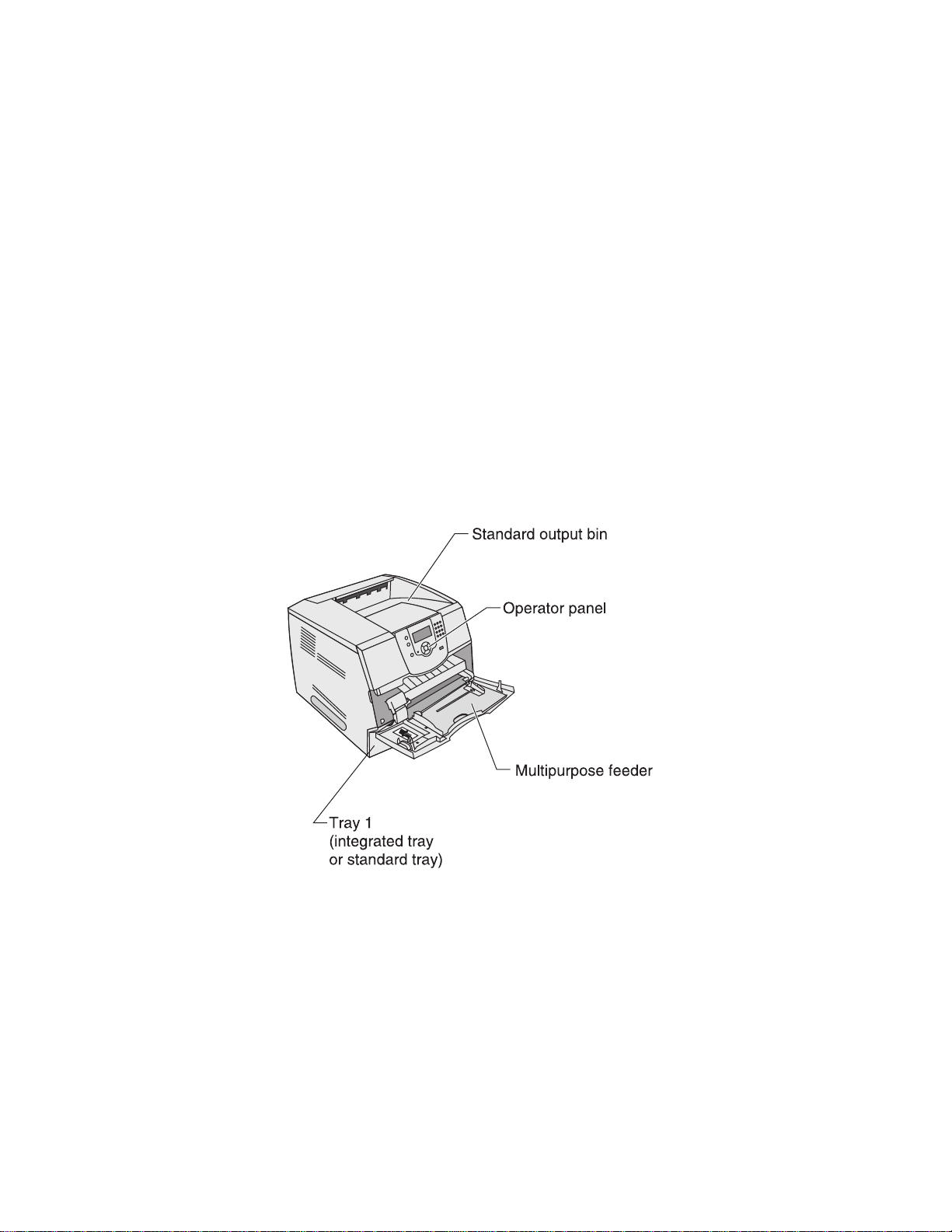
C onfigured model
The following illustration s hows a standard network printer.
1-2 S ervic e Ma nual
Page 23

Specifications
Resolution
• 1200 1200 dpi
• 2400 Image Quality
• 1200 Image Quality
• 600 x 600 dpi
Data streams
• PostScript 3 emulation
• PCL 6 emulation
•
•
Print speed and performance print speed
Performance
Performance speed depends on:
•
Interface to the host (USB, parallel, network)
• Host system and application
• Page complexity and content
• Printer options installed or selected
• Available printer memory
• Media size and type
• Resolution
Time to first print
NA
1200 dpi 600 dpi 1200 dpi 600 dpi 1200 600 dpi
Simplex printing from Ready on full-size media (seconds)
Letter
8.5 in. x 11 in.
A4
8.3 in. x 11.7 in.
Legal
8.5 in. x 14 in.
11.7 6.0 12.1 8.5 12.1 8.5
17.0 11.4 22.7 13.0 22.7 13.0
14.5 12.1 24.3 24.3 24.3 13.5
e-STUDIO 500P
NA
Simplex printing from Power Saver on full-size media (seconds)
Simplex Letter 25.3 28.2 28.2
The test job consists of the character “A” followed by a form-feed (single page job). The first copy time is
defined as the elapsed time from pressing Enter on the PC keyboard to the page exiting to the output bin. All
tests pick paper from the indicated tray, and the page exits into the primary output bin.
General information 1-3
Page 24

Memory c onfiguration
Memory type
S tanda rd DR AM (MB )
Optional memory (MB )
(100 pin DDR S DR AM unbuffered
DIMMs)
Maximum (MB )
128 and 512MB available
e-S TU DIO 500P
128
640
Depending upon the options and features used, additional memory may be required to optimize performance.
Availa ble memory options
Optional 128MB
a nd 512MB S DR AM DIMMs are ava ilable from T os hiba..
Operating clearances
P rinter s ide Meas urement
Left a nd right side 12 in. (30.48 cm)
Front 20 in. (50. 8 cm)
R ear 12 in. ( 30.48 cm)
Top* 54 in. (137.16 cm)
* Allow clearance above the printer front door c lea rance and for adding
options, s uch as additional input drawers
1-4 S ervic e Ma nual
Page 25

Dimensions
Description Height Width Depth Weight
Printer
e-STUDIO 500P
Options
Duplex 500 page option 2.13 in 15.6 in 23.4 in 11 lb
500-Sheet drawer 5.3 in.
2,000-Sheet 11.8 in.
Envelope option* (closed position) 7.72 in.
Envelope option* (support fully extended)
* Envelope option fits within height and width of printer.
16.0 i
(406 mm)
(134 mm)
(300 mm)
12.28 in.
n 17.2 in. 20.2 in.
(436 mm)
15.6 in.
(398 mm)
15.6 in.
(398 mm)
2
(513 mm)
20.5 in.
(520 mm)
19.5 in.
(495 mm)
(196 mm)
(312 mm)
51.6 lb
(23.1 kg)
7 lb
(3.2 kg)
31 lb
(14.1 kg)
4 lb
(1.8 kg)
4 lb
(1.8 kg)
General information 1-5
Page 26

Power requirements
Average nominal power requirements for the base printer configuration (110 volt). Power levels are shown in
watts (W). Maximum current is given in Amperes (A).
Printing states
Off (all models) .05 W .05 W .05 W
Idle—average power
Power Saver on 20 W 20 W 20 W
Power Saver off 90 W 95 W 95 W
Continuous printing 675 W 830 W 830 W
Printing—maximum current
100 V 7.8 A 8.9 A 8.9 A
120 V 7.2 A 8.0 A 8.0 A
e-STUDIO 500P
230 V 3.4 A 4.3 A 4.3 A
Electrical specifications
Low voltage model
•
100 to 127 V ac at 50 to 60 Hz nominal
• 90 to 137 V ac, extreme
High voltage model
•
220 to 240 V ac at 50 to 60 Hz nominal (not available in all countries)
• 190 to 259 V ac, extreme
Notes:
• Using a 220 to 110 power converter with the 110 volt printer is not recommended.
• All models are ENERGY STAR qualified.
• The default timeout to power saver is 30 minutes for all models.
1-6 Service Manual
Page 27

Environment
Printer temperature and humidity
• Operating
• Storage and shipping environment (packaged)
• Storage environment (unpacked)
Acoustics
All measurements are made in accordance with ISO 7779 and conform with ISO 9296.
– Temperature: 16 to 32° C (60° to 90° F)
– Relative humidity: 8 to 80%
– Altitude: 10,000 ft. (0 to 3,048 meters)
– Temperature: -40° to 43° C (-40° to 110° F)
– Relative humidity: 5% to 95%
– Altitude: equivalent to 10,300 meters (0 to 34,000 feet)
– Temperature: 0° to 40° C (32° to 104° F)
– Relative humidity: 5% to 80%
Model Status
1 Meter average
sound pressure
Simplex printing
Duplex printing
e-STUDIO 500P
Note: Measurements apply to 300 dpi, 600 dpi, and 1200 dpi printing.
Idle (standby mode)
Simplex printing
Duplex printing
Simplex printing
Duplex printing
53 dBA 6.7 Bels
55 dBA N/M Bels
32 dBA 4.7 Bels
54 dBA 6.8 Bels
57 dBA N/M Bels
55 7.0
58 N/M
Declared sound
power
General information 1-7
Page 28
Media s pecifications
Paper and s pec ialty media guidelines
P rint media is paper, ca rd stoc k, trans par enc ies, la bels , and en velopes . Thi s pr inter pr ovides hi gh qual ity
printing on a variety of print media. You must cons ider a num ber of things conce r ning pr int me dia befor e you
print, incl udi ng:
• S uppor ted pr int me di a
• S electing pr int medi a
• S toring pr int medi a
• Avoiding j ams
We recommend tha t you t ry a limited s am ple of any pape r or s pecialty media you a re cons i dering us ing wi th the
printer befor e pur chasi ng large qua nt ities .
S uppor ted prin t m edia
The followi ng tables provide infor mation on sta nd a r d and optiona l sour ces for bot h input a nd o ut pu t trays and
bins .
• P r int media s ize s
• P r in t media weights
• Media wei ght s s upp or ted in opt ional ou tpu t bins
• Media sizes suppo r ted in the finis her
• Media wei ght s s upp or ted in the finisher
Note: If you u s e a pri nt medi a s ize not lis ted, sele c t the nex t larger s ize.
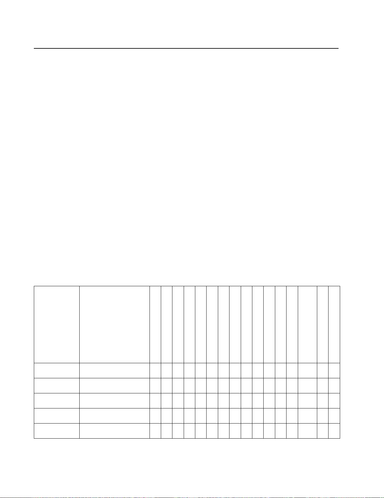
P rint media s iz es
P rint media
s iz e
( ]
indic ates
s upport)
A4 210 x 297 m m
A5 148 x 210 m m
J IS B 5 182 x 257 m m
Letter 215.9 x279.4 mm
Lega l 215.9 x 355.6 mm
Dimens ions
(UAT — univers ally
ad justable tray )
(8.27 x 11. 7 in. ) ] ] ] ] ]
(5.83 x 8. 27 in.)
(7.17 x 10. 1 in. )
(8 . 5 x 11 in .)
(8 . 5 x 14 in .)
250-s he et tray
500-s he et tray
250-s he et drawer (option)
250 UAT (option)
500-s he et drawer (option)
400 UAT (option)
Multipurpo s e feeder
2000-s heet drawer (option)
E nvelo pe feeder ( option)
Duplex unit ( option)
] ] ] ] ]
] ] ] ] ]
] ] ] ] ]
] ] ] ] ]
S tandard o utput bin
Output expander (option)
5-bin mailbox (option )
Hig h-c apacity
ou tput s tacker (o ption )
S tapleS mart ou tpu t bin
S tapleS mart F inish er
1-8 S er v i c e Ma nu al
Page 29

P rint media s izes (continued)
P rint media
s iz e
( ] indic ates
s upport)
Dimens ions
(UAT — univers ally
ad justable tray )
E xecutive 184. 2 x 266.7 mm
(7.25 x 10.5 in.)
1
216 x 330 mm
F olio
(8 . 5 x 13 in.)
S tatement1 139.7 x 215. 9 mm
(5 .5 x 8. 5 in.)
Universal
2, 3
139.7 x 210 mm to
215.9 x 355. 6 mm
(5.5 x 8.27 in. to 8.5 x 14 ]
in.)
69.85 x 127 mm to
215.9 x 355. 6 mm
(2.75 x 5 in. to 8. 5 x 14 ] ]
in.)
148 x 182 mm to
215.9 x 355. 6 mm
(5.8 3 x 7.17 in. to 8 .5 x 14 ]
in.)
76.2 x 127 mm to 215. 9 x
355.6 mm4
(3 x 5 in. to 8.5 x 14 in.)
76.2 x 177. 8 mm to 215.9
x 355. 6 mm
(3 x 7 in. to 8.5 x 14 in.)
7 ¾ E nvelope 98.4 x 190.5 mm
(3.875 x 7.5 in.)
9 E nvelope 98.4 x 225.4 mm
(3.875 x 8.9 in.)
10 E nvelope 104.8 x 241.3 mm
(4.12 x 9.5 in.)
DL E nvelope 110 x 220 mm
(4.33 x 8.66 in.)
C 5 E nvelope 162 x 229 mm
(6.38 x 9.01 in.)
B 5 E nvelope 176 x 250 mm
(6.93 x 9.84 in.)
250-s heet tray
500-s heet tray
250-s heet drawer (option)
250 UAT (option)
500-s heet drawer (option)
400 UAT (option)
Multipu rpo s e feeder
2000-s heet d rawer (option)
E nvelope feeder (option)
Duplex unit (option)
] ] ] ] ]
] ] ] ]
] ] ]
] ] ]
] ] ]
] ] ]
] ] ]
] ] ]
] ] ]
S ta nda rd output bin
Output expa nder (option)
5-bin mailbox (option)
High-ca pac ity
output stacker (option)
S tapleS mart o utput bin
S tapleS mart F inisher
G eneral informa tion 1-9
Page 30
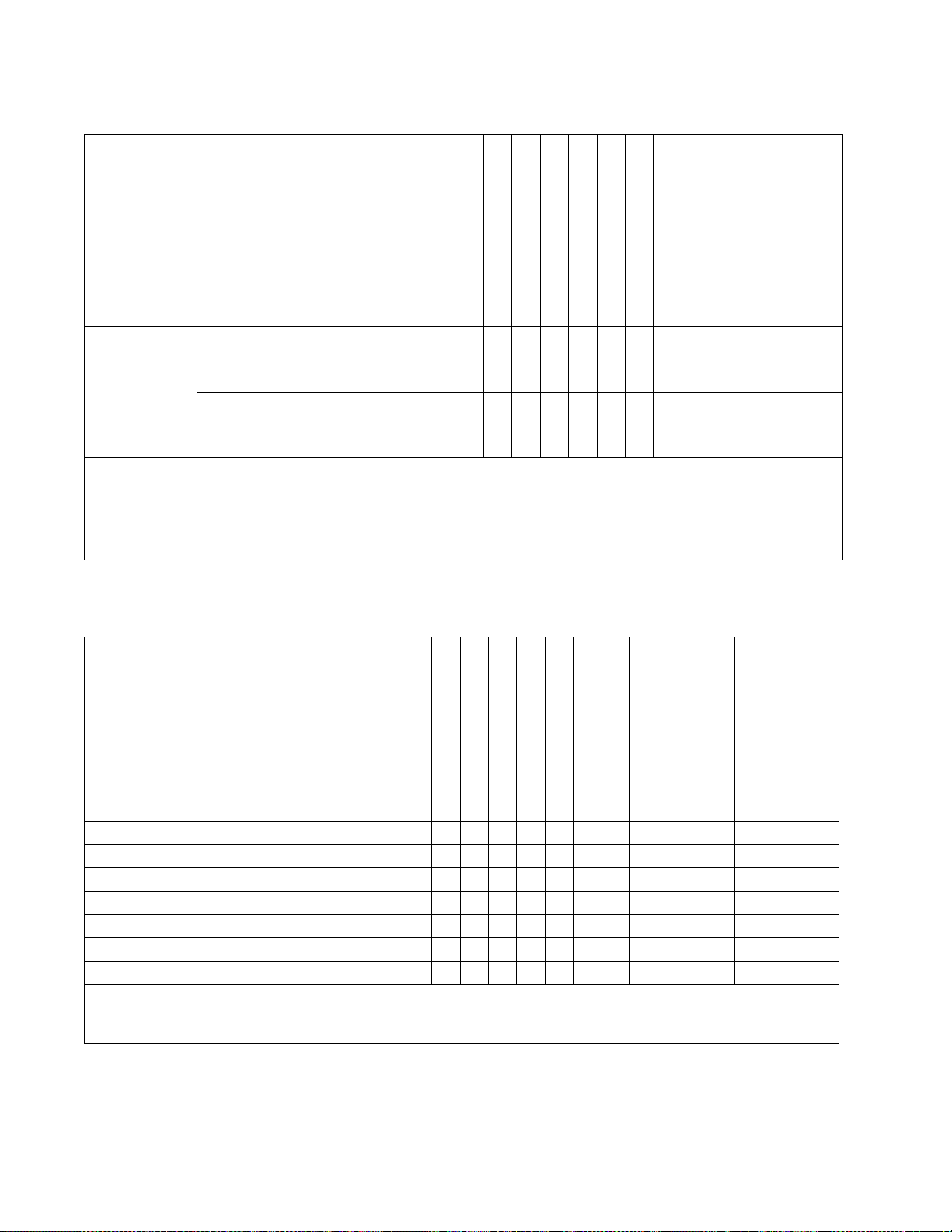
P rint m edia s iz es (c ontinued)
P rint medi a
s ize
(X i n dic ate s
s uppor t)
Other
E nvelope1
Dime ns ions
(UAT — univ ers ally
ad jus table tray )
98.4 x 162 mm
X X X
to 176 x 250 mm
500-s hee t drawer (o ption)
Multipurpos e feeder
2000-s heet drawer (optio n)
E nvelope feeder (option)
Duplex un it ( option)
S tandard o utput bin
(3.87 x 6.38 in.
to 6. 93 x 9.84 in.)
98.4 x 162 mm X X X
to 229 x 342 mm
(3.87 x 6.38 in.
to 9. 01x 12. 76 in.)
1
This s ize does not appear in the P aper Size menu until Tray S ize S ens ing is turned off.
2
This s ize s etting formats the pa ge for 215. 9 x 355.6 mm (8.5 x 14 in.) unles s the size is specified by the softwa re
application.
3
N o univers al s upport for the following options: 2000-sheet drawer, E nvelope Feeder, 5-bin mailbox.
4
3.5 in. setting not s upported if other options are installed a bove the 250 univers ally adjustable tray.
P rint m edia types
P rint m edia
500-s hee t drawer (o ption)
Multipurpos e feeder
2000-s heet drawe r
E nvelope feeder
Duplex un it
S tandard output bin
Paper X X X X X
C ard stock X X X X
Trans pa rencies X X X
Paper labels1 X X
1
P rinting label a pplications on the printer requires a s pecia l label fus er c lea ner which preve nts duplexing. T he label fuse r
cleane r is included with a special label ca rtridge for la bel applications.
1-10 S ervice Ma nual
Page 31

Print media weights
Print media weight
Print media Type
Integrated tray and
optional
500-sheet drawer
Paper Xerographic or
business paper
60 to 176 g/m
long (16 to 47 lb
bond)
Card stock—
maximum
(grain long)1
Card stock—
maximum
(grain short)
Index Bristol 163 g/m
Tag 163 g/m
Cover 176 g/m
Index Bristol 199 g/m
1
Tag 203 g/m
Cover 216 g/m
2
(90 lb) 120 g/m2 (67 lb) n/a
2
(100 lb) 120 g/m2 (74 lb)
2
(65 lb) 135 g/m2 (50 lb)
2
(110 lb) 163 g/m2 (90 lb)
2
(125 lb) 163 g/m2 (100 lb)
2
(80 lb) 176 g/m2 (65 lb)
Transparencies Laser printer 138 to 146 g/m
(37 to 39 lb bond)
Labels—maximum
2
Paper 180 g/m2
(48 lb bond)
Dual-web paper 180 g/m
2
(48 lb bond)
Polyester 220 g/m
2
(59 lb bond)
5
Vinyl
300 g/m
2
(92 lb liner)
Integrated forms Pressure-
140 to 135 g/m
2
grain
2
2
Multipurpose
feeder
~
~
60 to 135 g/m2 grain
long (16 to 36 lb
bond)
138 to 146 g/m
(37 to 39 lb bond)
163 g/m
2
(43 lb bond)
163 g/m
2
(43 lb bond)
220 g/m
2
(59 lb bond)
260 g/m
2
(78 lb liner)
140 to 135 g/m2
Envelope
feeder
n/a 60 to 135 g/m
2
sensitive area
(must enter the
printer first)
Paper base
(grain long)
Envelopes
100% cotton content
maximum
weight—24 lb
1
Grain short is preferred for papers over 135 g/m2.
2
Printing label applications on your printer requires a special label fuser cleaner which prevents duplexing.
3
28 lb envelopes are limited to 25% cotton content.
4
Includes envelopes fed from the multipurpose feeder only
Sulfite, woodfree or up to
100% cotton
bonds
75 to 135 g/m
(20 to 36 lb bond)
Not recommended 60 to 105 g/m
2
75 to 135 g/m2
(20 to 36 lb bond)
2
(16 to 28 lb
3, 4
bond)
60 to 105 g/m
(16 to 28 lb
3
bond)
2
.
PAGES 1-12 THRU 1-14 HAVE BEEN REMOVED INTENTIONALLY FROM THIS DOCUMENT
2000-Sheet
drawer
2
(16 to 36 lb
bond)
General information 1-11
Page 32

Selecting print media
Selecting the appropriate print media for your printer helps you avoid printing problems. The following sections
contain guidelines for choosing the correct print media for your printer.
• Paper
• Transparencies
• Envelopes
• Labels
• Card stock
Paper
For the best print quality, use 75 g/m2 (20 lb) xerographic, grain long paper. Try a sample of any paper you are
considering using with the printer before buying large quantities.
When loading paper, note the recommended print side on the paper package, and load paper accordingly.
Paper characteristics
The following paper characteristics affect print quality and reliability. We recommend that you follow these
guidelines when evaluating new paper stock.
Weight
The printer can automatically feed paper weights from 60 to 176 g/m2 (16 to 47 lb bond) grain long in the
integrated and optional 500–sheet trays and paper weights from 60 to 135 g/m
the multipurpose feeder. Paper lighter than 60 g/m (16 lb) might not be stiff
enough to feed properly, causing jams. For best performance, use 75 g/m
using paper narrower than 182 x 257 mm (7.2 x 10.1 in.), make sure the weight is greater than or equal to 90 g/
2
m
(24 lb bond).
2
(16 to 36 lb bond) grain long in
2
2
(20 lb bond) grain long paper. When
Unacceptable paper
The following papers are not recommended for use with the printer:
• Chemically treated papers used to make copies without carbon paper, also known as carbonless papers,
carbonless copy paper (CCP), or no carbon required (NCR) paper
• Preprinted papers with chemicals that may contaminate the printer
• Preprinted papers that can be affected by the temperature in the printer fuser
• Preprinted papers that require a registration (the precise print location on the page) greater than ±0.09 in.,
such as optical character recognition (OCR) forms
• In some cases, you can adjust registration with your software application to successfully print on these
forms.
• Coated papers (erasable bond), synthetic papers, thermal papers
• Rough-edged, rough or heavily textured surface papers or curled papers
• Recycled papers containing more than 25% post-consumer waste that do not meet DIN 19 309
• Recycled paper having a weight less than 60 g/m
2
(16 lb)
• Multiple-part forms or documents
General information 1-15
Page 33

• For best performance and to minimize jams, do not use envelopes that:
– Have excessive curl or twist.
– Are stuck together or damaged in any way.
– Contain windows, holes, perforations, cutouts or embossing.
– Use metal clasps, string ties, or metal folding bars.
– Have an interlocking design.
– Have postage stamps attached.
– Have any exposed adhesive when the flap is in the sealed or closed position.
– Have nicked edges or bent corners.
– Have rough, cockle, or laid finishes.
• Use envelopes that can withstand temperatures of 225°C (437°F) without sealing, excessive curling,
wrinkling, or releasing hazardous emissions. If you have any doubts about the envelopes you are
considering using, check with the envelope supplier.
• Load only one size of envelope at a time in the envelope feeder.
• A combination of high humidity (over 60%) and the high printing temperatures may seal the envelopes.
Labels
Your printer can print on many labels designed for use with laser printers. These labels are supplied in
•
letter size, A4 size, and legal size sheets. Label adhesives, face sheet (printable stock), and topcoats must
be able to withstand temperatures of 225°C (437°F) and pressure of 25 pounds per square inch (psi).
• Try a sample of any labels you are considering using with the printer before purchasing a large quantity.
Note: Labels are one of the most difficult print media for laser printers. All printer models require a special fuser
cleaner for label applications to optimize feed reliability.
After printing approximately 10,000 pages of labels (or each time you replace the print cartridge), complete the
following steps to maintain printer feeding reliability:
1. Print five sheets of paper.
2. Wait approximately five seconds.
3. Print five more sheets of paper.
When printing on labels:
• Set the Paper Size/Type menu item to Labels in the Paper Menu. You can set the Paper Size/Type from the
printer operator panel, the printer driver, the Local Printer Setup Utility, or from MarkVision.
• Do not load labels with paper or transparencies in the same source; mixing print media can cause feeding
problems.
• Do not use label sheets with a slick backing material.
• Use full label sheets. Partial sheets may cause labels to peel off during printing, resulting in a jam. Partial
sheets also contaminate your printer and your cartridge with adhesive, and could void your printer and
cartridge warranties.
• Use labels that can withstand temperatures of 225°C (437°F) without sealing, excessive curling, wrinkling,
or releasing hazardous emissions.
• Do not print within 1 mm (0.04 in.) of the edge of the label, of the perforations, or between die-cuts of the
label.
• Do not use label sheets that have adhesive to the edge of the sheet. We recommend zone coating of the
adhesive at least 1 mm (0.04 in.) away from edges. Adhesive material contaminates your printer and could
void your warranty.
• If zone coating of the adhesive is not possible, a 3 mm (0.125 in.) strip should be removed on the leading
and driver edge, and a non-oozing adhesive should be used.
• Remove a 3 mm (0.125 in.) strip from the leading edge to prevent labels from peeling inside the printer.
General information 1-17
Page 34

• Portrait orientation is preferred, especially when printing bar codes.
• Do not use labels that have exposed adhesive.
Card stock
Card stock is single ply, and has a large array of properties, such as the moisture content, thickness, and texture,
that can significantly affect print quality. See “Supported print media” on page 1-8 for information on the
preferred weight and for the grain direction of print media.
Try a sample of any card stock you are considering using with the printer before purchasing a large quantity.
After printing approximately 10,000 pages of card stock (or each time you replace the print cartridge), complete
the following steps to maintain printer feeding reliability:
1. Print five sheets of paper.
2. Wait approximately five seconds.
3. Print five more sheets of paper.
When printing on card stock:
• Set the Paper Type menu item in the Paper Menu to Card Stock from the operator panel, from the printer
driver, in the Local Printer Setup Utility, or from MarkVision.
• Be aware that preprinting, perforation, and creasing can significantly affect the print quality and cause print
media handling or jamming problems.
• Avoid using card stock that may release hazardous emissions when heated.
• Do not use preprinted card stock manufactured with chemicals that may contaminate the printer.
Preprinting introduces semi-liquid and volatile components into the printer.
• We recommend the use of grain short card stock.
Storing print media
Use the following guidelines to avoid paper feeding problems and uneven print quality.
• Store paper in an environment where the temperature is approximately 21°C (70°F) and the relative
humidity is 40%.
• Store cartons of paper on a pallet or shelf rather than directly on the floor.
• If you store individual packages of paper out of the original carton, make sure they rest on a flat surface so
the edges do not buckle or curl.
• Do not place anything on top of paper packages.
• Store paper in its original wrapper until you load it into the printer.
1-18 Service Manual
Page 35

Avoiding jams
Use appropriate print media (paper, transparencies, labels, and card stock) to help ensure trouble-free printing.
See “Supported print media” on page 1-8 for more information.
Note: Try a limited sample of any print media you are considering using with the printer before purchasing large
quantities.
By selecting the appropriate print media and loading it properly, you can avoid most jams.
The following hints can help you avoid jams:
• Use only recommended print media.
• Do not overload the print media sources. Make sure the stack height does not exceed the maximum height
indicated by the stack line on the labels in the sources.
• Do not load wrinkled, creased, damp, or curled print media.
• Flex, fan, and straighten print media before you load it. If jams do occur with print media, try feeding one
sheet at a time through the multipurpose feeder.
• Do not use print media that you have cut or trimmed yourself.
• Do not mix print media sizes, weights, or types in the same print media source.
• Make sure the recommended print side is loaded in the source according to your simplex or duplex needs.
• Keep print media stored in an acceptable environment. See “Storing print media” on page 1-18.
• Do not remove trays during a print job.
• Push all trays in firmly after loading them.
• Make sure the guides in the trays are properly positioned for the size of print media you have loaded. Make
sure the guides are not placed too tightly against the stack of print media.
Print area
The printable area is limited to within 4.2 mm (0.167 in.) of all edges of the media. Any information placed
outside this specified printable area does not print.
Tools required
Flat-blade screwdrivers, various sizes
Phillips screwdrivers, various sizes
7.0 mm nut driver
5.5 mm wrench
Needlenose pliers
Diagonal side cutters
Spring hook
Feeler gauges
Analog or digital multimeter
Parallel wrap plug 1319128
Twinax/serial debug cable 1381963
Flash light (optional)
General information 1-19
Page 36

Acronyms
BLDC Brushless DC motor
CRU Customer Replaceable Unit
CSU Customer setup
DIMM Dual Inline Memory Module
DRAM Dynamic Random Access Memory
DVM Digital multimeter
EDO Enhanced Data Out
EEPROM Electrically Erasable Programable Read-Only Memory
EP Electrophotographic process
EPROM Erasable Programmable Read-Only Memory
ESD Electrostatic Discharge
FRU Field Replaceable Unit
GB Gigabyte
HCIT High-capacity Input Tray
HVPS High Voltage Power Supply
ITC Internal Tray Card
LASER Light Amplification by Stimulated Emission of Radiation
LCD Liquid Crystal Display
LED Light-Emitting Diode
LVPS Low Voltage Power Supply
MPF Multipurpose feeder
MROM Masked Read Only Memory
MS Microswitch
NVRAM Nonvolatile Random Access Memory
OEM Original Equipment Manufacturer
OPT Optical Sensor
PC Photoconductor
pel Picture element
POR Power-On Reset
POST Power-On Self Test
PP Parts Packet
PWM Pulse Width Modulation
RIP Raster Imaging Processor
ROM Read Only Memory
SDRAM Synchronous Dynamic Random Access Memory
SIMM Single Inline Memory Module
SRAM Static Random Access Memory
UAT Universally Adjustable Tray)
UPR Used Parts Return
V ac Volts alternating current
V dc Volts direct current
VOM Volt Ohmmeter
1-20 Service Manual
Page 37

2. Diagnostic information
Start
CAUTION: Remove the power cord from the printer or wall outlet before you connect or
disconnect any cable or electronic board or assembly for personal safety and to prevent damage
to the printer. Use the handholds on the side of the printer. Make sure your fingers are not under
the printer when you lift or set the printer down.
Use the service error code, user status message, user error message, symptom table, service checks, and
diagnostic aids in this chapter to determine the corrective action necessary to repair a malfunctioning printer.
They will lead you to solutions or service checks, including use of various tests.
Symptom tables
If your machine completes the “Power-On Self Test (POST) sequence” on page 2-4 without an error, and you
have a symptom, go to “Symptom tables” on page 2-5. Locate your symptom, and take the appropriate action.
The following tables are available:
• “Base printer symptoms” on page 2-5
• “High-capacity feeder (2000-sheet) symptoms” on page 2-5
• “Paper tray symptoms” on page 2-6
• “Duplex option symptoms” on page 2-6
• “Envelope feeder symptoms” on page 2-6
• “Output expander” on page 2-6
• “StapleSmart finisher” on page 2-7
Service errors (9xx.xx’s)
If a service error code appears while you are working on the machine, go to “Service error codes” on
page 2-8, and take the indicated action for that error.
Service error codes are indicated by a three-digit error code followed by a period and additional numbers in the
format XXX.YY. In most cases, five digits are shown.
User status and attendance messages
•
User status messages provide the user with information on the current status of the printer. Ready displays
on the first line of the display unless invoked, and then Power Saver displays. If a user status message is
displayed, go to “User status displays” on page 2-31.
• User attendance messages are indicated by a two or three-digit error code that provides the user with
information that explains a problem with a print cartridge, paper jam, option, port, and so on. If a user error
message displays, go to “User attendance messages” on page 2-32 and “User attendance
messages—paper jams and paper handling errors (2xx.xx)” on page 2-44.
Additional information
•
“Power-On Self Test (POST) sequence” on page 2-4
• “Understanding the printer operator panel” on page 2-2
• “Understanding the menus” on page 2-3
• “Diagnostics mode” on page 3-2
• “Configuration menu (CONFIG MENU)” on page 3-25
• “Theory” on page 3-31
• “Paper feed jams” on page 3-33
• “Parts catalog” on page 7-1
Diagnostic information 2-1
Page 38

Understanding the printer operator panel
The operator panel on your printer is a 4-line back-lit gray scale display that can show both graphics and text.
The Back, Menu, and Stop buttons are located to the left of the display, the navigation buttons are located
below the display, and the numeric pad is located to the right of the display.
Display panel
Numeric pad
Indicator light
Navigation buttons
The use of the buttons and the layout of the display panel are described in the following table.
Select button
Operator panel
Button Function
Press the Back button to return to the last screen you viewed.
Back
Menu
Stop
Navigation buttons
Note: Changes made on the screen will not be applied if you press the Back
button.
Press the Menu button to open the menu index.
Note: The printer must be in the Ready state to access the menu index. A
message indicating the menus are unavailable will appear if the printer is not
ready.
Press Stop to stop the mechanical operation of the printer. After pressing Stop,
the message Stopping is displayed. When the printer has stopped, the status
line in the operator panel will show Stopped, and a list of options will appear.
The Up or Down buttons are used to move up and down lists.
When navigating through a list using the Up or Down button, the cursor
moves one line at a time. Pressing the Down button at the bottom of the
screen changes the screen to the next whole page.
The Left or Right buttons are used to move within a screen such as
moving from one menu index item to another. They are also used to
scroll through text that will not fit on the screen.
The Select button is used to initiate action on a selection. Press Select
when the cursor appears next to the selection you want such as
following a link, submitting a configuration item, or when you want to
start or cancel a job.
USB port
2-2 Service Manual
Page 39

Operator panel (continued)
Button Function
Numeric pad The numeric pad consists of numbers, a pound '#' sign, and a backspace button.
The 5 button has a raised bump for non-visual orientation.
The numbers are used to enter numeric values for items like quantities or PINs.
The backspace is used to delete the number to the left of the cursor. Pressing the
backspace multiple times will delete additional entries.
The pound '#' sign is not used.
Display panel
Understanding the menus
The diagram shows the menu index on the operator panel and the menus and items available under each menu.
For more information about menus and menu items, refer to the Menus and Messages book on your
Publications CD.
The display panel shows messages and graphics describing the current state of
the printer and indicating possible printer problems you must resolve.
The top line of the display is the header line. If applicable, it will contain the
graphic indicating the Back button can be used. It will also display the current
status, and the Supplies (Warnings) status. If multiple warnings are present,
each warning will be separated by a comma.
The other three lines of the display are the body of the screen. This is where you
view printer status, supplies messages, show-me screens, and make selections.
Menu
Paper Menu
Reports
Settings
Paper Menu
Default Source
Paper Size/Type
Configure MP
Envelope Enhance
Substitute Size
Paper Texture
Paper Weight
Paper Loading
Custom Types
Universal Setup
Bin Setup
Reports
Menu Settings Page
Device Statistics
Network Setup Page
Network <x> Setup Page
Profiles List
Print Quick Ref
NetWare Setup Page
Print Fonts
Print Directory
Settings
Setup Menu
Finishing Menu
Quality Menu
Utilities Menu
PDF Menu
PostScript Menu
PCL Menu
HTML Menu
Image Menu
Network/Ports
IPv6
TCP/IP
Standard Network
Network <x>
Standard USB
USB <x>
Front USB
Parallel
Parallel <x>
Serial <x>
NetWare
AppleTalk
LexLink
Diagnostic information 2-3
Security
Max Invalid PIN
Job Expiration
Encrypt Disk
Help
Print All
Print Quality
Printing Guide
Supplies Guide
Media Guide
Menu Map
Information Guide
Connection Guide
Moving Guide
Page 40

Power-On Self Test (POST) sequence
When you turn the printer on, it performs a Power-On Self Test. Check for correct POST functioning of the base
printer by observing the following:
1. The LED turns comes on.
2. The operator panel turns on.
3. A partial row of pixels are displayed.
4. The operator panel display clears.
5. Another row of pixels appears.
6. The operator panel display clears again.
7. The operator panel displays system information. For example:
*128MB 449MH
8. The fuser lamp turns on. The fuser takes longer to warm up from a cold start than a warm start.
9. The operator panel LED starts blinking.
10. A clock face appears on the display.
If present, the following errors or messages may display:
• Close Door or Insert Cartridge display if the upper front cover is open or the print cartridge is
missing.
• Any cartridge errors, such as Defective Cartridge, Prebate Violation, or Missing
Cartridge.
11. Ready appears on the display.
12. The main fan turns on.
13. The main drive motor turns on.
14. The developer drive assembly drives the developer shaft in the toner cartridge.
15. The exit rollers turn.
2-4 Service Manual
Page 41

Symptom tables
Base printer symptoms
Symptom Action
Dead machine Go to “Dead machine service check” on page 2-80.
Operator panel—one or more buttons do
not work.
Operator panel—none of the buttons work. Go to “No buttons work” on page 2-106.
Operator panel—display is blank. Printer
sounds 5 beeps.
Operator panel—display is blank. Go to “Operator panel display” on page 2-107
Operator panel continuously displays all
diamonds and does not complete POST.
Paper feed problems—base printer or
integrated 500-sheet paper tray
Paper jams at exit of redrive assembly—
duplex option not installed.
Paper jams at exit of redrive assembly—
duplex option installed.
Fuser solenoid fails to operate. Go to “Fuser solenoid service check” on page 2-94.
Print quality—black page Go to “Print quality—all black page” on page 2-116.
Print quality—blank page Go to “Print quality—blank page” on page 2-117.
Print quality—light print Go to “Print quality—light print” on page 2-121.
Print quality—background Go to “Print quality—background” on page 2-118.
Print quality—residual image Go to “Print quality—residual image” on page 2-120.
Print quality—skew Go to “Paper feed service check” on page 2-112.
Print quality—banding Go to “Print quality—banding” on page 2-119.
Print quality—random marks Go to “Print quality—random marks” on page 2-117.
Print quality—toner on backside of printed
page.
Print quality—vertical black bands on edge
of copy.
Unable to clear a 32-Unsupported Print
Cartridge user error message.
Go to “One or more operator panel buttons fail” on
page 2-106.
Go to “Operator panel display” on page 2-107.
Go to “Operator panel service check” on page 2-106.
Go to “Paper feed service check” on page 2-112.
Go to “Paper feed service check” on page 2-112.
Go to “Duplex option service check” on page 2-82.
Go to “Print quality—toner on backside of printed page” on
page 2-121.
Go to “Print quality—black bands on outer edges of the
page” on page 2-120.
Go to “Signature button assembly service check” on
page 2-122.
High-capacity feeder (2000-sheet) symptoms
Symptom Action
The printer does not recognize the highcapacity feeder installed.
Paper feed problem with the high-capacity
feeder.
Go to “High-capacity feeder input tray service check” on
page 2-95.
Go to “High-capacity feeder input tray service check” on
page 2-95.
Diagnostic information 2-5
Page 42

Paper tray symptoms
Symptom Action
Paper feed problem with 250-Sheet Paper
Tray.
Paper feed problem with 500-Sheet Paper
Tray.
Media fails to pass through from the lower
attached Paper Tray option to the next
higher mounted option.
Duplex option symptoms
Symptom Action
Paper feed problem with Duplex. Go to “Duplex option service check” on page 2-82.
Paper jams at Paper Removal Tray. Go to “Duplex option service check” on page 2-82.
Paper skews in the Duplex Option. Go to “Duplex option service check” on page 2-82.
Paper fails to pass from lower option
through the Duplex Option.
Envelope feeder symptoms
Symptom Action
Envelopes do not feed from the envelope
feeder.
Envelopes do not feed properly into base
printer.
Go to “Input tray(s) service check” on page 2-102.
Go to “Input tray(s) service check” on page 2-102.
Go to “Input tray(s) service check” on page 2-102.
Go to “Duplex option service check” on page 2-82.
Go to “Envelope feeder service check” on page 2-84.
Go to “Envelope feeder service check” on page 2-84.
2-6 Service Manual
Page 43

Diagnostic information 2-7
Page 44

Messages and error codes
Service error codes
Service error codes are generally non-recoverable except in an intermittent condition when you can POR the
printer to temporarily recover from the error condition.
Service error codes (9xx.xx)
Error
code
900 .xx RIP Software Go to “900.xx Error code
901 .xx Engine flash error Indicates that the flash which the system
902 .xx Engine software error These errors indicate an unrecoverable
903 .xx Paperport link driver
904 .xx Interface violation by
905 .xx Interface violation by
906 .xx RIP interface driver error These errors indicate an unrecoverable
910 .xx DC pick motor
Sub
codes
Display text Description Action
service check” on page 2-75.
Replace the system board.
See“System board and inner
shield removal” on page 4-76.
Replace the system board. See
“System board and inner
shield removal” on page 4-76.
Replace the system board. See
“System board and inner
shield removal” on page 4-76.
Replace the system board. See
“System board and inner
shield removal” on page 4-76.
Replace the system board. See
“System board and inner
shield removal” on page 4-76.
Replace the system board. See
“System board and inner
shield removal” on page 4-76.
Go to “Paper feed service
check” on page 2-112.
error
RIP
Paperport device
acceleration stall
(autocompensator
motor).
board code is programmed into is bad.
Replace the system board.
system software error.
These errors indicate an unrecoverable
system software error.
These errors indicate an unrecoverable
system software error.
These errors indicate an unrecoverable
system software error.
system software error.
• Check autocompensator cable
connectors
• Check autocompensator for binds
911 .00 DC pick motor excessive
PWM
912 .00 DC pick motor
underspeed error
913 .00 DC pick motor
overspeed error
914 .00 DC pick motor no
encoder feedback
917 .00 Problem with transfer—
transfer servo start error.
2-8 Service Manual
• Check system board
• Check autocompensator motor
• Check system board
• Check autocompensator
• Check system board
• Check autocompensator
Check autocompensator assembly Go to “Paper feed service
• Check HVPS
• Check system board
• Check HVPS/input sensor/toner
sensor cable.
Go to “Paper feed service
check” on page 2-112.
Go to “Paper feed service
check” on page 2-112.
Go to “Paper feed service
check” on page 2-112.
check” on page 2-112.
Go to “Transfer roll service
check” on page 2-128.
Page 45

Service error codes (9xx.xx) (continued)
Error
code
920 .01 Hot roll took too long to
920 .02 Hot roll fell too far below
920 .03 Hot roll too cool when
920 .04 Hot roll too cool when
Sub
codes
Display text Description Action
heat up after
transitioning to new
enhanced mode
(standby control only.
Fuser page count
between 0 and 99,999.
the desired temperature
while in standby. Fuser
page between 0 and
99,999.
checking for slope
change in standby.
Fuser page count
between 0 and 99,999.
heating to desired
temperature after slope
change (standby control
only). Fuser page count
between 0 and 99,999.
• Bad thermistor, circuit or cabling.
• Fuser not receiving sufficient AC
power.
• Poor supply line voltage.
• Low wattage or incorrect lamp.
• Incorrect hot roll.
• Bad thermistor, circuit or cabling.
• Fuser not receiving sufficient AC
power.
• Poor supply line voltage.
• Low wattage or incorrect lamp.
• Incorrect hot roll.
• Bad thermistor, circuit or cabling.
• Fuser not receiving sufficient AC
power.
• Poor supply line voltage.
• Low wattage or incorrect lamp.
• Incorrect hot roll.
• Bad thermistor, circuit or cabling.
• Fuser not receiving sufficient AC
power.
• Poor supply line voltage.
• Low wattage or incorrect lamp.
• Incorrect hot roll.
Go to “920.xx—Cold fuser
service check” on page 2-87.
Go to “920.xx—Cold fuser
service check” on page 2-87.
Go to “920.xx—Cold fuser
service check” on page 2-87.
Go to “920.xx—Cold fuser
service check” on page 2-87.
920 .06 Fuser is not increasing
in temperature even
though the lamp has
been on for an extended
time. Fuser page count
between 0 and 99,999.
920. .07 Fuser has been below
the desired temperature
for too long while media
is in the nip. Fuser page
count between 0 and
99,999.
920 .11 Hot roll took too long to
heat up after
transitioning to new
enhanced mode. Fuser
page count between
100,000 and 199,999.
• Fuser is not receiving AC power.
• Poor supply line voltage.
• Bad thermistor, circuit, or cabling.
• Very noisy thermistor signal.
• Fuser not receiving AC power.
• Poor supply line voltage.
• Excessive load on the fuser.
• Low voltage or incorrect lamp.
• Abrupt change in temperature that
has disrupted control.
• Incorrect hot roll.
• Bad thermistor, circuit, or cabling.
• Very noisy thermistor signal.
• Fuser not receiving AC power.
• Poor supply line voltage.
• Low voltage or incorrect lamp.
• Incorrect hot roll.
Go to “920.xx—Cold fuser
service check” on page 2-87.
Go to “920.xx—Cold fuser
service check” on page 2-87.
Go to “920.xx—Cold fuser
service check” on page 2-87.
Diagnostic information 2-9
Page 46

Service error codes (9xx.xx) (continued)
Error
code
920 .12 Hot roll fell too far below
920 .13 Hot roll too cool while
920 .14 Hot roll too cool when
920 .16 Fuser is not increasing
Sub
codes
Display text Description Action
the desired temperature
while printing. Fuser
page count between
100,000 and 199,999.
checking for slope
change. Fuser page
count between 100,000
and 199,999.
heating to desired
temperature after slope
change. Fuser page
count between 100,000
and 199,999.
in temperature even
though the lamp has
been on for an extended
time. Fuser page count
between 100,000 and
199,999.
• Bad thermistor, circuit, or cabling.
• Noisy thermistor signal.
• Fuser not receiving AC power.
• Poor supply line voltage.
• Low voltage or incorrect lamp.
• Incorrect hot roll.
• Bad thermistor, circuit, or cabling.
• Noisy thermistor signal.
• Fuser not receiving AC power.
• Poor supply line voltage.
• Low voltage or incorrect lamp.
• Incorrect hot roll.
• Bad thermistor, circuit, or cabling.
• Noisy thermistor signal.
• Fuser not receiving AC power.
• Poor supply line voltage.
• Low voltage or incorrect lamp.
• Incorrect hot roll.
• Fuser is not receiving AC power.
• Poor supply line voltage.
Go to “920.xx—Cold fuser
service check” on page 2-87.
Go to “920.xx—Cold fuser
service check” on page 2-87.
Go to “920.xx—Cold fuser
service check” on page 2-87.
Go to “920.xx—Cold fuser
service check” on page 2-87.
920 .17 Fuser has been below
the desired temperature
for too long while the
media is in the nip.
Fuser page count
between 100,000 and
199,999.
920 .21 Hot roll took too long to
heat up after
transitioning to new
enhanced mode. Fuser
page count between
200,000 and 299,999.
• Bad thermistor, circuit, or cabling.
• Very noisy thermistor signal.
• Fuser not receiving AC power.
• Poor supply line voltage.
• Excessive load on the fuser.
• Low voltage or incorrect lamp.
• Incorrect hot roll.
• Abrupt change in temperature that
has disrupted control.
• Bad thermistor, circuit, or cabling.
• Fuser not receiving AC power.
• Poor supply line voltage.
• Low voltage or incorrect lamp.
• Incorrect hot roll.
Go to “920.xx—Cold fuser
service check” on page 2-87.
Go to “920.xx—Cold fuser
service check” on page 2-87.
2-10 Service Manual
Page 47

Service error codes (9xx.xx) (continued)
Error
code
920 .22 Hot roll fell too far below
920 .23 Hot roll too cool while
920 .24 Hot roll too cool when
920 .26 Fuser is not increasing
Sub
codes
Display text Description Action
the desired temperature
while printing. Fuser
page count between
200,000 and 299,999.
checking for slope
change. Fuser page
count between 200,000
and 299,999.
heating to desired
temperature after slope
change. Fuser page
count between 200,000
and 299,999.
in temperature even
though the lamp has
been on for an extended
tim. Fuser page count
between 200,000 and
299,999.
• Bad thermistor, circuit, or cabling.
• Noisy thermistor signal.
• Fuser not receiving AC power.
• Poor supply line voltage.
• Low voltage or incorrect lamp.
• Incorrect hot roll.
• Bad thermistor, circuit, or cabling.
• Noisy thermistor signal.
• Fuser not receiving AC power.
• Poor supply line voltage.
• Low voltage or incorrect lamp.
• Incorrect hot roll.
• Bad thermistor, circuit, or cabling.
• Noisy thermistor signal.
• Fuser not receiving AC power.
• Poor supply line voltage.
• Low voltage or incorrect lamp.
• Incorrect hot roll.
• Fuser is not receiving AC power.
• Poor supply line voltage.
Go to “920.xx—Cold fuser
service check” on page 2-87.
Go to “920.xx—Cold fuser
service check” on page 2-87.
Go to “920.xx—Cold fuser
service check” on page 2-87.
Go to “920.xx—Cold fuser
service check” on page 2-87.
920 .27 Fuser has been below
the desired temperature
for too long while media
is in the nip. Fuser page
count between 200,000
and 299,999.
920 .31 Under temperature
during steady state
control. Fuser page
count between 300,000
and 399,999.
• Bad thermistor, circuit, or cabling.
• Very noisy thermistor signal.
• Fuser not receiving AC power.
• Poor supply line voltage.
• Excessive load on the fuser.
• Low voltage or incorrect lamp.
• Incorrect hot roll.
• Abrupt change in temperature that
has disrupted control.
• Bad thermistor, circuit, or cabling.
• Fuser not receiving AC power.
• Poor supply line voltage.
• Low voltage or incorrect lamp.
• Incorrect hot roll.
Go to “920.xx—Cold fuser
service check” on page 2-87.
Go to “920.xx—Cold fuser
service check” on page 2-87.
Diagnostic information 2-11
Page 48

Service error codes (9xx.xx) (continued)
Error
code
920 .32 Hot roll fell too far below
920 .33 Hot roll too cool while
920 .34 Hot roll too cool when
920 .36 Fuser is not increasing
Sub
codes
Display text Description Action
desired temperature
while printing. Fuser
page count between
300,000 and 399,999.
checking for slope
change. Fuser page
count between 300,000
and 399,999.
heating to desired
temperature after slope
change. Fuser page
count between 300,000
and 399,999.
in temperature even
though the lamp has
been on for an extended
time. Fuser page count
between 300,000 and
399,999.
• Bad thermistor, circuit, or cabling.
• Noisy thermistor signal.
• Fuser not receiving AC power.
• Poor supply line voltage.
• Low voltage or incorrect lamp.
• Incorrect hot roll.
• Bad thermistor, circuit, or cabling.
• Noisy thermistor signal.
• Fuser not receiving AC power.
• Poor supply line voltage.
• Low voltage or incorrect lamp.
• Incorrect hot roll.
• Bad thermistor, circuit, or cabling.
• Noisy thermistor signal.
• Fuser not receiving AC power.
• Poor supply line voltage.
• Low voltage or incorrect lamp.
• Incorrect hot roll.
• Fuser is not receiving AC power.
• Poor supply line voltage.
Go to “920.xx—Cold fuser
service check” on page 2-87.
Go to “920.xx—Cold fuser
service check” on page 2-87.
Go to “920.xx—Cold fuser
service check” on page 2-87.
Go to “920.xx—Cold fuser
service check” on page 2-87.
920 .37 Fuser has been below
the desired temperature
for too long while media
is in the nip. Fuser page
count between 300,000
and 399,999.
920 .41 Hot roll took too long to
heat up after
transitioning to new
enhanced mode. Fuser
page count between
400,000 and 499,999.
• Bad thermistor, circuit, or cabling.
• Very noisy thermistor signal.
• Fuser not receiving AC power.
• Poor supply line voltage.
• Excessive load on the fuser.
• Low voltage or incorrect lamp.
• Incorrect hot roll.
• Abrupt change in temperatures that
has disrupted control.
• Bad thermistor, circuit, or cabling.
• Fuser not receiving AC power.
• Poor supply line voltage.
• Low voltage or incorrect lamp.
• Incorrect hot roll.
Go to “920.xx—Cold fuser
service check” on page 2-87.
Go to “920.xx—Cold fuser
service check” on page 2-87.
2-12 Service Manual
Page 49

Service error codes (9xx.xx) (continued)
Error
code
920 .42 Hot roll fell too far below
920 .43 Hot roll too cool while
920 .44 Hot roll too cool when
920 .46 Fuser is not increasing
Sub
codes
Display text Description Action
the desired temperature
while printing. Fuser
page count between
400,000 and 499,999.
chickens for slope
change. Fuser page
count between 400,000
and 499,999.
heating to desired
temperature after slop
change. Fuser page
count between 400,000
and 499,999
in temperature even
though the lamp has
been on for an extended
time. Fuser page count
between 400,000 and
499,999.
• Bad thermistor, circuit, or cabling.
• Noisy thermistor signal.
• Fuser not receiving AC power.
• Poor supply line voltage.
• Low voltage or incorrect lamp.
• Incorrect hot roll.
• Bad thermistor, circuit, or cabling.
• Noisy thermistor signal.
• Fuser not receiving AC power.
• Poor supply line voltage.
• Low voltage or incorrect lamp.
• Incorrect hot roll.
• Bad thermistor, circuit, or cabling.
• Noisy thermistor signal.
• Fuser not receiving AC power.
• Poor supply line voltage.
• Low voltage or incorrect lamp.
• Incorrect hot roll.
• Fuser is not receiving AC power.
• Poor supply line voltage.
Go to “920.xx—Cold fuser
service check” on page 2-87.
Go to “920.xx—Cold fuser
service check” on page 2-87.
Go to “920.xx—Cold fuser
service check” on page 2-87.
Go to “920.xx—Cold fuser
service check” on page 2-87.
920 .47 Fuser has been below
the desired temperature
for too long while media
is in the nip. Fuser page
count between 400,000
and 499,999.
920 .51 Hot roll took too long to
heat up after
transitioning to new
enhanced mode. Fuser
page count more than
500,000.
• Bad thermistor, circuit, or cabling.
• Very noisy thermistor signal.
• Fuser not receiving AC power.
• Poor supply line voltage.
• Excessive load on the fuser.
• Low voltage or incorrect lamp.
• Incorrect hot roll.
• Abrupt change in temperatures that
has disrupted control.
• Bad thermistor, circuit, or cabling.
• Fuser not receiving AC power.
• Poor supply line voltage.
• Low voltage or incorrect lamp.
• Incorrect hot roll.
Go to “920.xx—Cold fuser
service check” on page 2-87.
Go to “920.xx—Cold fuser
service check” on page 2-87.
Diagnostic information 2-13
Page 50

Service error codes (9xx.xx) (continued)
Error
code
92 .52 Hot roll fell too far below
920 .53 Hot roll too cool while
920 .54 Hot roll too cool when
920 .56 Fuser is not increasing
Sub
codes
Display text Description Action
desired temperature
while printing. Fuser
page count more than
500,000.
checking for slope
change. Fuser page
count more than
500,000.
heating to desired
temperature after slope
change. Fuser page
count more than
500,000.
in temperature even
though the lamp has
been on for an extended
time. Fuser count more
than 500,000.
• Bad thermistor, circuit, or cabling.
• Noisy thermistor signal.
• Fuser not receiving AC power.
• Poor supply line voltage.
• Low voltage or incorrect lamp.
• Incorrect hot roll.
• Bad thermistor, circuit, or cabling.
• Noisy thermistor signal.
• Fuser not receiving AC power.
• Poor supply line voltage.
• Low voltage or incorrect lamp.
• Incorrect hot roll.
• Bad thermistor, circuit, or cabling.
• Noisy thermistor signal.
• Fuser not receiving AC power.
• Poor supply line voltage.
• Low voltage or incorrect lamp.
• Incorrect hot roll.
• Fuser is not receiving AC power.
• Poor supply line voltage.
Go to “920.xx—Cold fuser
service check” on page 2-87.
Go to “920.xx—Cold fuser
service check” on page 2-87.
Go to “920.xx—Cold fuser
service check” on page 2-87.
Go to “920.xx—Cold fuser
service check” on page 2-87.
920 .57 Fuser has been below
the desired temperature
for too long while media
is in the nip. Fuser page
count more than
500,000.
920 .91 Hot roll took too long to
heat up after
transitioning to new
enhanced mode. Fuser
page count not
available.
• Bad thermistor, circuit, or cabling.
• Very noisy thermistor signal.
• Fuser not receiving AC power.
• Poor supply line voltage.
• Excessive load on the fuser.
• Low voltage or incorrect lamp.
• Incorrect hot roll.
• Abrupt change in temperatures that
has disrupted control.
• Bad thermistor, circuit, or cabling.
• Fuser not receiving AC power.
• Poor supply line voltage.
• Low voltage or incorrect lamp.
• Incorrect hot roll.
Go to “920.xx—Cold fuser
service check” on page 2-87.
Go to “920.xx—Cold fuser
service check” on page 2-87.
2-14 Service Manual
Page 51

Service error codes (9xx.xx) (continued)
Error
code
920 .92 Hot roll fell too far below
920 .93 Hot roll too cool while
920 .94 Hot roll too cool when
Sub
codes
Display text Description Action
desired temperature
while printing. Fuser
page count not
available.
checking for slope
change. Fuser page
count not available.
heating to desired
temperature after slope
change. Fuser page
count not available.
• Bad thermistor, circuit, or cabling.
• Noisy thermistor signal.
• Fuser not receiving AC power.
• Poor supply line voltage.
• Excessive load on the fuser.
• Low voltage or incorrect lamp.
• Incorrect hot roll.
• Bad thermistor, circuit, or cabling.
• Noisy thermistor signal.
• Fuser not receiving AC power.
• Poor supply line voltage.
• Excessive load on the fuser.
• Low voltage or incorrect lamp.
• Incorrect hot roll.
• Bad thermistor, circuit, or cabling.
• Noisy thermistor signal.
• Fuser not receiving AC power.
• Poor supply line voltage.
• Excessive load on the fuser.
• Low voltage or incorrect lamp.
• Incorrect hot roll.
Go to “920.xx—Cold fuser
service check” on page 2-87.
Go to “920.xx—Cold fuser
service check” on page 2-87.
Go to “920.xx—Cold fuser
service check” on page 2-87.
920 .96 Fuser is not increasing
in temperature even
though the lamp has
been on for an extended
time. Fuser page count
not available.
920 .97 Fuser has been below
the desired temperature
for too long while media
is in the nip. Fuser page
count not available.
922 .02 Hot roll took too long to
reach the beginning
lamp detection
temperature. Fuser
page count between 0
and 99,999.
• Fuser is not receiving AC power.
• Poor supply line voltage.
• Bad thermistor, circuit, or cabling.
• Very noisy thermistor signal.
• Fuser not receiving AC power.
• Poor supply line voltage.
• Excessive load on the fuser.
• Low voltage or incorrect lamp.
• Abrupt change in temperatures that
has disrupted control.
• Low wattage or incorrect lamp.
• Bad thermistor, circuit, or cabling.
• Fuser not receiving sufficient AC
power.
• Poor supply line voltage.
Go to “920.xx—Cold fuser
service check” on page 2-87.
Go to “920.xx—Cold fuser
service check” on page 2-87.
Go to “922.xx—Cold fuser
check” on page 2-89.
Diagnostic information 2-15
Page 52

Service error codes (9xx.xx) (continued)
Error
code
922 .03 Hot roll reached final
922 .04 Hot roll timed out in
922 .06 Hot roll did not reach
922 .07 Fuser has taken too long
Sub
codes
Display text Description Action
lamp detection
temperature but took
longer than largest time
in lookup table. Fuser
page count between 0
and 99,999.
trying to reach the final
lamp detection
temperature. Fuser
page count between 0
and 99,999.
operating temperature in
time (new enhanced
control). Fuser page
count between 0 and
99,999.
to reach desired
temperature after
increasing interrupt gap.
Fuser page count
between 0 and 99,999.
• Low wattage or incorrect lamp.
• Bad thermistor, circuit, or cabling.
• Fuser not receiving sufficient AC
power.
• Poor supply line voltage.
• Low wattage or incorrect lamp.
• Bad thermistor, circuit, or cabling.
• Fuser not receiving sufficient AC
power.
• Poor supply line voltage.
• Low wattage or incorrect lamp.
• Bad thermistor, circuit, or cabling.
• Fuser not receiving sufficient AC
power.
• Poor supply line voltage.
• Low wattage or incorrect lamp.
• Bad thermistor, circuit, or cabling.
• Fuser not receiving sufficient AC
power.
• Poor supply line voltage.
Go to “922.xx—Cold fuser
check” on page 2-89.
Go to “922.xx—Cold fuser
check” on page 2-89.
Go to “922.xx—Cold fuser
check” on page 2-89.
Go to “922.xx—Cold fuser
check” on page 2-89.
922 .12 Hot roll took too long to
reach the beginning
lamp detection
temperature. Fuser
page count between
100,000 and 199,999.
922 .13 Hot roll reached final
lamp detection
temperature but took
longer than largest time
in lookup table. Fuser
page count between
100,000 and 199,999.
922 .14 Hot roll timed out in
trying to reach the final
lamp detection
temperature. Fuser
page count between
100,000 and 199,999.
922 .15 After hot roll lamp
detection, did not roll
over to steady state
control in time. Fuser
page count between
100,000 and 199,999.
• Low wattage or incorrect lamp.
• Bad thermistor, circuit, or cabling.
• Fuser not receiving sufficient AC
power.
• Poor supply line voltage.
• Low wattage or incorrect lamp.
• Bad thermistor, circuit, or cabling.
• Fuser not receiving sufficient AC
power.
• Poor supply line voltage.
• Low wattage or incorrect lamp.
• Bad thermistor, circuit, or cabling.
• Fuser not receiving sufficient AC
power.
• Poor supply line voltage.
The control code has been lost. Go to “922.xx—Cold fuser
Go to “922.xx—Cold fuser
check” on page 2-89.
Go to “922.xx—Cold fuser
check” on page 2-89.
Go to “922.xx—Cold fuser
check” on page 2-89.
check” on page 2-89.
2-16 Service Manual
Page 53

Service error codes (9xx.xx) (continued)
Error
code
922 .16 Hot roll did not reach
922 .17 Fuser has taken too long
922 .22 Hot roll took too long to
922 .23 Hot roll reached final
Sub
codes
Display text Description Action
operating temperature in
time (new enhanced
control). Fuser page
count between 100,000
and 199,999.
to reach desired
temperature after
increasing interpage
gap. Fuser page count
between 100,000 and
199,999.
reach the beginning
lamp detection
temperature. Fuser
page count between
200,000 and 299,999.
lamp detection
temperature but took
longer than largest time
in lookup table. Fuser
page count between
200,000 and 299,999.
• Low wattage or incorrect lamp.
• Bad thermistor, circuit, or cabling.
• Fuser not receiving sufficient AC
power.
• Poor supply line voltage.
• Low wattage or incorrect lamp.
• Bad thermistor, circuit, or cabling.
• Fuser not receiving sufficient AC
power.
• Poor supply line voltage.
• Low wattage or incorrect lamp.
• Bad thermistor, circuit, or cabling.
• Fuser not receiving sufficient AC
power.
• Poor supply line voltage.
• Low wattage or incorrect lamp.
• Bad thermistor, circuit, or cabling.
• Fuser not receiving sufficient AC
power.
• Poor supply line voltage.
Go to “922.xx—Cold fuser
check” on page 2-89.
Go to “922.xx—Cold fuser
check” on page 2-89.
Go to “922.xx—Cold fuser
check” on page 2-89.
Go to “922.xx—Cold fuser
check” on page 2-89.
922 .24 Hot roll timed out in
trying to reach the final
lamp detection
temperature. Fuser
page count between
200,000 and 299,999.
922 .25 After hot roll lamp
detection, did not roll
over to steady state
control in time. Fuser
page count between
200,000 and 299,999.
922 .26 Hot roll did not reach
operating temperature in
time (new enhanced
control). Fuser page
count between 200,000
and 299,999.
922 .27 Fuser has taken too long
to reach desired
temperature after
increasing interpage
gap. Fuser page count
between 200,000 and
299,999.
• Low wattage or incorrect lamp.
• Bad thermistor, circuit, or cabling.
• Fuser not receiving sufficient AC
power.
• Poor supply line voltage.
The control code has been lost. Go to “922.xx—Cold fuser
• Low wattage or incorrect lamp.
• Bad thermistor, circuit, or cabling.
• Fuser not receiving sufficient AC
power.
• Poor supply line voltage.
• Low wattage or incorrect lamp.
• Bad thermistor, circuit, or cabling.
• Fuser not receiving sufficient AC
power.
• Poor supply line voltage.
Go to “922.xx—Cold fuser
check” on page 2-89.
check” on page 2-89.
Go to “922.xx—Cold fuser
check” on page 2-89.
Go to “922.xx—Cold fuser
check” on page 2-89.
Diagnostic information 2-17
Page 54

Service error codes (9xx.xx) (continued)
Error
code
922 .32 Hot roll took too long to
922 .33 Hot roll reached final
922 .34 Hot roll timed out in
922 .35 After hot roll lamp
Sub
codes
Display text Description Action
reach the beginning
lamp detection
temperature. Fuser
page count between
300,000 and 399,999.
lamp detection
temperature but took
longer than largest time
in lookup table. Fuser
page count between
300,000 and 399,999.
trying to reach the final
lamp detection
temperature. Fuser
page count between
300,000 and 399,999.
detection, did not roll
over to steady state
control in time. Fuser
page count between
300,000 and 399,999.
• Low wattage or incorrect lamp.
• Bad thermistor, circuit, or cabling.
• Fuser not receiving sufficient AC
power.
• Poor supply line voltage.
• Low wattage or incorrect lamp.
• Bad thermistor, circuit, or cabling.
• Fuser not receiving sufficient AC
power.
• Poor supply line voltage.
• Low wattage or incorrect lamp.
• Bad thermistor, circuit, or cabling.
• Fuser not receiving sufficient AC
power.
• Poor supply line voltage.
The control code has been lost. Go to “922.xx—Cold fuser
Go to “922.xx—Cold fuser
check” on page 2-89.
Go to “922.xx—Cold fuser
check” on page 2-89.
Go to “922.xx—Cold fuser
check” on page 2-89.
check” on page 2-89.
922 .36 Hot roll did not reach
operating temperature in
time (new enhanced
control). Fuser page
count between 300,000
and 399,999.
922 .37 Fuser has taken too long
to reach desired
temperature after
increasing interpage
gap. Fuser page count
between 300,000 and
399,999.
922 .42 Hot roll took too long to
reach the beginning
lamp detection
temperature. Fuser
page count between
400,000 and 499,999.
922 .43 Hot roll reached final
lamp detection
temperature but took
longer than largest time
in lookup table. Fuser
page count between
400,000 and 499,999.
• Low wattage or incorrect lamp.
• Bad thermistor, circuit, or cabling.
• Fuser not receiving sufficient AC
power.
• Poor supply line voltage.
• Low wattage or incorrect lamp.
• Bad thermistor, circuit, or cabling.
• Fuser not receiving sufficient AC
power.
• Poor supply line voltage.
• Low wattage or incorrect lamp.
• Bad thermistor, circuit, or cabling.
• Fuser not receiving sufficient AC
power.
• Poor supply line voltage.
• Low wattage or incorrect lamp.
• Bad thermistor, circuit, or cabling.
• Fuser not receiving sufficient AC
power.
• Poor supply line voltage.
Go to “922.xx—Cold fuser
check” on page 2-89.
Go to “922.xx—Cold fuser
check” on page 2-89.
Go to “922.xx—Cold fuser
check” on page 2-89.
Go to “922.xx—Cold fuser
check” on page 2-89.
2-18 Service Manual
Page 55

Service error codes (9xx.xx) (continued)
Error
code
922 .44 Hot roll timed out in
922 .45 After hot roll lamp
922 .46 Hot roll did not reach
922 .47 Fuser has taken too long
Sub
codes
Display text Description Action
trying to reach the final
lamp detection
temperature. Fuser
page count between
400,000 and 499,999.
detection, did not roll
over to steady state
control in time. Fuser
page count between
400,000 and 499,999.
operating temperature in
time (new enhanced
control). Fuser page
count between 400,000
and 499,999.
to reach desired
temperature after
increasing interpage
gap. Fuser page count
between 400,000 and
499,999.
• Low wattage or incorrect lamp.
• Bad thermistor, circuit, or cabling.
• Fuser not receiving sufficient AC
power.
• Poor supply line voltage.
The control code has been lost. Go to “922.xx—Cold fuser
• Low wattage or incorrect lamp.
• Bad thermistor, circuit, or cabling.
• Fuser not receiving sufficient AC
power.
• Poor supply line voltage.
• Low wattage or incorrect lamp.
• Bad thermistor, circuit, or cabling.
• Excessive load on the fuser.
• Fuser not receiving sufficient AC
power.
• Poor supply line voltage.
Go to “922.xx—Cold fuser
check” on page 2-89.
check” on page 2-89.
Go to “922.xx—Cold fuser
check” on page 2-89.
Go to “922.xx—Cold fuser
check” on page 2-89.
922 .52 Hot roll took too long to
reach the beginning
lamp detection
temperature. Fuser
page count stopped at
500,000 to preserve
data.
922 .53 Hot roll reached final
lamp detection
temperature but took
longer than largest time
in lookup table. Fuser
page count stopped at
500,000 to preserve
data.
922 .54 Hot roll timed out in
trying to reach the final
lamp detection
temperature. Fuser
page count stopped at
500,000 to preserve
data.
922 .55 After hot roll lamp
detection, did not roll
over to steady state
control in time. Fuser
page count stopped at
500,000 to preserve
data.
• Low wattage or incorrect lamp.
• Bad thermistor, circuit, or cabling.
• Fuser not receiving sufficient AC
power.
• Poor supply line voltage.
• Low wattage or incorrect lamp.
• Bad thermistor, circuit, or cabling.
• Fuser not receiving sufficient AC
power.
• Poor supply line voltage.
• Low wattage or incorrect lamp.
• Bad thermistor, circuit, or cabling.
• Fuser not receiving sufficient AC
power.
• Poor supply line voltage.
The control code has been lost. Go to “922.xx—Cold fuser
Go to “922.xx—Cold fuser
check” on page 2-89.
Go to “922.xx—Cold fuser
check” on page 2-89.
Go to
“922.xx—Cold fuser
check” on page 2-89.
check” on page 2-89.
Diagnostic information 2-19
Page 56

Service error codes (9xx.xx) (continued)
Error
code
922 .56 Hot roll did not reach
922 .57 Fuser has taken too long
922 .92 Hot roll took too long to
922 .93 Hot roll reached ‘final
Sub
codes
Display text Description Action
operating temperature in
time (new enhanced
control). Fuser page
count stopped at
500,000 to preserve
data.
to reach desired
temperature after
increasing interpage
gap. Fuser page count
stopped at 500,000 to
preserve data.
reach the beginning
lamp detection
temperature. Fuser
page count not
available.
lamp detection
temperature’ but took
longer than largest time
in lookup table. Fuser
page count not
available.
• Low wattage or incorrect lamp.
• Bad thermistor, circuit, or cabling.
• Fuser not receiving sufficient AC
power.
• Poor supply line voltage.
• Low wattage or incorrect lamp.
• Excessive load on the fuser.
• Fuser not receiving sufficient AC
power.
• Poor supply line voltage.
• Low wattage or incorrect lamp.
• Bad thermistor, circuit, or cabling.
• Fuser not receiving sufficient AC
power.
• Poor supply line voltage.
• Low wattage or incorrect lamp.
• Bad thermistor, circuit, or cabling.
• Fuser not receiving sufficient AC
power.
• Poor supply line voltage.
Go to “922.xx—Cold fuser
check” on page 2-89.
Go to “922.xx—Cold fuser
check” on page 2-89.
Go to “922.xx—Cold fuser
check” on page 2-89.
Go to “922.xx—Cold fuser
check” on page 2-89.
922 .94 Hot roll timed out in
trying to reach the final
lamp detection
temperature. Fuser
page count not
available.
922 .95 After hot roll lamp
detection, did not roll
over to steady state
control in time. Fuser
page count not
available.
922 .96 Hot roll did not reach
operating temperature in
time (new enhanced
control). Fuser page
count not available.
922 .97 Fuser has taken too long
to reach desired
temperature after
increasing interpage
gap. Fuser page count
not available.
• Low wattage or incorrect lamp.
• Bad thermistor, circuit, or cabling.
• Fuser not receiving sufficient AC
power.
• Poor supply line voltage.
Control code has been lost. Go to “922.xx—Cold fuser
• Low wattage or incorrect lamp.
• Bad thermistor, circuit, or cabling.
• Fuser not receiving sufficient AC
power.
• Poor supply line voltage.
• Low wattage or incorrect lamp.
• Excessive load on the fuser.
• Fuser not receiving sufficient AC
power.
• Poor supply line voltage.
Go to “922.xx—Cold fuser
check” on page 2-89.
check” on page 2-89.
Go to “922.xx—Cold fuser
check” on page 2-89.
Go to “922.xx—Cold fuser
check” on page 2-89.
2-20 Service Manual
Page 57

Service error codes (9xx.xx) (continued)
Error
code
923 .01 Fuser over temperature.
923 .11 Fuser over temperature.
923 .21 Fuser over temperature.
923 .31 Fuser over temperature.
923 .41 Fuser over temperature.
Sub
codes
Display text Description Action
Fuser page count
between 0 and 99,999.
Fuser page count
between 100,000 and
199,999.
Fuser page count
between 200,000 and
299,999.
Fuser page count
between 300,000 and
399,999.
Fuser page count
between 400,000 and
499,999.
• Short in the thermistor circuit.
• Noisy thermistor signal
• Fuser is actually overheating due to
hardware faults.
• Short in the thermistor circuit.
• Noisy thermistor signal
• Fuser is actually overheating due to
hardware faults.
• Short in the thermistor circuit.
• Noisy thermistor signal
• Fuser is actually overheating due to
hardware faults.
• Short in the thermistor circuit.
• Noisy thermistor signal
• Fuser is actually overheating due to
hardware faults.
• Short in the thermistor circuit.
• Noisy thermistor signal
• Fuser is actually overheating due to
hardware faults.
Go to “923.xx—Hot fuser
service check” on page 2-90.
Go to “923.xx—Hot fuser
service check” on page 2-90.
Go to “923.xx—Hot fuser
service check” on page 2-90.
Go to “923.xx—Hot fuser
service check” on page 2-90.
Go to “923.xx—Hot fuser
service check” on page 2-90.
923 .51 Fuser over temperature.
Fuser page count
stopped at 500,000 to
preserve data.
923 .91 Fuser over temperature.
Fuser page count not
available.
924 .01 Open thermistor check
failure. Fuser page
count between 0 and
99,999.
924 .11 Open thermistor check
failure. Fuser page
count between 100,000
and 199,999.
924 .21 Open thermistor check
failure. Fuser page
count between 200,000
and 299,999.
924 .31 Open thermistor check
failure. Fuser page
count between 300,000
and 399,999.
• Short in the thermistor circuit.
• Noisy thermistor signal
• Fuser is actually overheating due to
hardware faults.
• Short in the thermistor circuit.
• Noisy thermistor signal
• Fuser is actually overheating due to
hardware faults.
• Noisy thermistor signal.
• Intermittent connection.
• Thermistor cable not connected or
thermistor actually open.
• Noisy thermistor signal.
• Intermittent connection.
• Thermistor cable not connected or
thermistor actually open.
• Noisy thermistor signal.
• Intermittent connection.
• Thermistor cable not connected or
thermistor actually open.
• Noisy thermistor signal.
• Intermittent connection.
• Thermistor cable not connected or
thermistor actually open.
Go to “923.xx—Hot fuser
service check” on page 2-90.
Go to “923.xx—Hot fuser
service check” on page 2-90.
Go to “924.xx—Hot fuser
service check” on page 2-91.
Go to “924.xx—Hot fuser
service check” on page 2-91.
Go to “924.xx—Hot fuser
service check” on page 2-91.
Go to “924.xx—Hot fuser
service check” on page 2-91.
Diagnostic information 2-21
Page 58

Service error codes (9xx.xx) (continued)
Error
code
924 .41 Open thermistor check
924 .51 Open thermistor check
924 .91 Open thermistor check
925 .01 Lamp detection
925 .02 Too hot to do lamp
Sub
codes
Display text Description Action
failure. Fuser page
count between 400,000
and 499,999.
failure. Fuser page
count over 500,000.
failure. Fuser page
count not available.
performed and found
error. Fuser page count
between 0 and 99,999.
detection and NVRAM
bit indicates previous
wrong lamp detected.
Fuser page count
between 0 and 99,999.
• Noisy thermistor signal.
• Intermittent connection.
• Thermistor cable not connected or
thermistor actually open.
• Noisy thermistor signal.
• Intermittent connection.
• Thermistor cable not connected or
thermistor actually open.
• Noisy thermistor signal.
• Intermittent connection.
• Thermistor cable not connected or
thermistor actually open.
• 115 V lamp in 220 V printer.
• Lamp has excessive wattage.
Attempting to POR machine after
receiving a 925.01.
Go to “924.xx—Hot fuser
service check” on page 2-91.
Go to “924.xx—Hot fuser
service check” on page 2-91.
Go to “924.xx—Hot fuser
service check” on page 2-91.
Go to “925.xx—Hot fuser
service check” on page 2-91.
Go to “925.xx—Hot fuser
service check” on page 2-91.
925 .11 Lamp detection
performed and found
error. Fuser page count
between 100,000 and
199,999.
925 .12 Too hot to do lamp
detection and NVRAM
bit indicates previous
wrong lamp detected.
Fuser page count
between 100,000 and
199,999.
925 .21 Lamp detection
performed and found
error. Fuser page count
between 200,000 and
299,999.
925 .22 Too hot to do lamp
detection and NVRAM
bit indicates previous
wrong lamp detected.
Fuser page count
between 200,000 and
299,999.
925 .31 Lamp detection
performed and found
error. Fuser page count
between 300,000 and
399,999.
• 115 V lamp in 220 V printer.
• Lamp has excessive wattage.
Attempting to POR machine after
receiving a 925.01.
• 115 V lamp in 220 V printer.
• Lamp has excessive wattage.
Attempting to POR machine after
receiving a 925.01.
• 115 V lamp in 220 V printer.
• Lamp has excessive wattage.
Go to “925.xx—Hot fuser
service check” on page 2-91.
Go to “925.xx—Hot fuser
service check” on page 2-91.
Go to “925.xx—Hot fuser
service check” on page 2-91.
Go to “925.xx—Hot fuser
service check” on page 2-91.
Go to “925.xx—Hot fuser
service check” on page 2-91.
2-22 Service Manual
Page 59

Service error codes (9xx.xx) (continued)
Error
code
925 .32 Too hot to do lamp
925 .41 Lamp detection
925 .42 Too hot to do lamp
925 .51 Lamp detection
925 .52 Too hot to do lamp
Sub
codes
Display text Description Action
detection and NVRAM
bit indicates previous
wrong lamp detected.
Fuser page count
between 300,000 and
399,999.
performed and found
error. Fuser page count
between 400,000 and
499,999.
detection and NVRAM
bit indicates previous
wrong lamp detected.
Fuser page count
between 400,000 and
499,999.
performed and found
error. Fuser page count
stopped at 500,000 to
preserve data.
detection and NVRAM
bit indicates previous
wrong lamp detected.
Fuser page count
stopped at 500,000 to
preserve data.
Attempting to POR machine after
receiving a 925.01.
• 115 V lamp in 220 V printer.
• Lamp has excessive wattage.
Attempting to POR machine after
receiving a 925.01.
• 115 V lamp in 220 V printer.
• Lamp has excessive wattage.
Attempting to POR machine after
receiving a 925.01.
Go to “925.xx—Hot fuser
service check” on page 2-91.
Go to “925.xx—Hot fuser
service check” on page 2-91.
Go to “925.xx—Hot fuser
service check” on page 2-91.
Go to “925.xx—Hot fuser
service check” on page 2-91.
Go to “925.xx—Hot fuser
service check” on page 2-91.
925 .91 Lamp detection
performed and found
error. Writes to the fuser
information chip have
been disabled due to a
previous write failure.
925 .92 Too hot to do lamp
detection and NVRAM
bit indicates previous
wrong lamp detected.
Writes to the fuser
information chip have
been disabled due to a
previous write failure.
927 .00 Service fan error. • Loose connector.
927 .01 Main fan stalled. • External blockage of fan
• 115 V lamp in 220 V printer.
• Lamp has excessive wattage.
Attempting to POR machine after
receiving a 925.01.
• External blockage of the fan,
preventing it from turning.
• Bad fan.
• Fan may not turn due to internal fan
problem.
Go to “925.xx—Hot fuser
service check” on page 2-91.
Go to “925.xx—Hot fuser
service check” on page 2-91.
Go to “Main fan” on
page 2-76.
Go to “Main fan” on
page 2-76.
Diagnostic information 2-23
Page 60

Service error codes (9xx.xx) (continued)
Error
code
927 .02 Cartridge fan stalled. • Loose connector.
927 .03 Main fan took too long to
927 .04 Main fan underspeed or
927 .05 Main fan overspeed
927 .06 Main fan capture data is
927 .07 Main fan capture data is
Sub
codes
Display text Description Action
• External blockage of the fan,
preventing it from turning.
• Bad fan.
ramp up.
stalled during speed
adjustment state.
during speed
adjustment state.
invalid and speed
control is at maximum in
fan control idle state.
invalid and speed
control is at maximum in
fan control adjustment
state.
• Loose connector.
• External blockage of the fan,
preventing it from turning.
• Bad fan.
• Corrupted feedback signal.
• Fan input voltage may be too low.
• Corrupted feedback signal.
• Fan input voltage may be too low.
Corrupted or non-existent feedback
signal.
Corrupted feedback signal. Go to “Main fan” on
Go to “Cartridge fan service
check” on page 2-76.
Go to “Main fan” on
page 2-76.
Go to “Main fan” on
page 2-76.
Go to “Main fan” on
page 2-76.
Go to “Main fan” on
page 2-76.
page 2-76.
929 .00 Toner sensor error—a
problem has been
detected with the toner
sensor.
929 .66 An error has been
detected. No home
windows has been
detected.
929 .67 No toner sensor
transition.
930 .00 An incorrect printhead
has been detected
932 .00 Printhead lost HSYNC. • Check printhead
933 .00 Mirror motor locked, no
first HSYNC received.
934 .00 Mirror motor lost lock • Check printhead
• Check the toner sensor
• Check cable
• Check system board
• Check toner cartridge.
• Check toner sensor
• Check toner sensor
• Check toner cartridge
Check the printhead Go to “Printhead service
• Check cables and connections
• Check system board
• Check printhead
• Check cables and connectors
• Check system board.
• Check cables and connections
• Check system board
Go to “Toner sensor service
check” on page 2-127.
Go to “Toner sensor service
check” on page 2-127.
Go to “Toner sensor service
check” on page 2-127.
check” on page 2-122.
Go to “Printhead service
check” on page 2-122.
Go to “Printhead service
check” on page 2-122.
Go to “Printhead service
check” on page 2-122.
2-24 Service Manual
Page 61

Service error codes (9xx.xx) (continued)
Error
code
936 .00 Mirror moor not up to
936 .10 No hall effect detected
936 .11 No hall effect detected
936 .20 Failed to stop within
936 .21 Failed to stop within
936 .30 No lock detected at
Sub
codes
Display text Description Action
speed
at motor start. Motor is
type 0.
at motor start. Motor is
type 1.
timeout, motor is type 0.
timeout, motor is type 1.
motor start for motor ID.
Motor is type 0.
• Check printhead
• Check system board
• Check cable connections
• Defective motor
• Severe gear blinds in gearbox
assembly
• System board
• Check cable connections
• Defective motor
• Severe gear binds in gearbox
assembly.
• System board
• Defective motor
• Defective system board
• Defective motor
• Defective system board
• Check for paper jams
• Gear binds
• Defective motor
• Check motor cable and connections
Go to “Printhead service
check” on page 2-122.
Go to “Main drive service
check” on page 2-105.
Go to “Main drive service
check” on page 2-105.
Go to “Main drive service
check” on page 2-105.
Go to “Main drive service
check” on page 2-105.
Go to “Main drive service
check” on page 2-105.
936 .31 No lock detected at
motor start for motor ID.
Motor is type 1.
936 .60 No lock detected at
normal motor start.
Motor is type 0.
936 .61 No lock detected at
normal motor start.
Motor is type 1.
936 .9 Stall detected during
speed control. Motor is
type 0.
936 .91 Stall detected during
speed control. Motor is
type 1.
• Check for paper jams
• Gear binds
• Defective motor
• Check motor cable and connections
• Check for paper jams
• Gear binds
• Defective motor
• Check motor cable and connections
• Check for paper jams
• Gear binds
• Defective motor.
• Defective motor cable
• Cable connections
• Defective cable
• Check cable connections
• Defective motor
• Paper jams
• Defective cable
• Check cable connections
• Defective motor
• Paper jams
Go to “Main drive service
check” on page 2-105.
Go to “Main drive service
check” on page 2-105.
Go to “Main drive service
check” on page 2-105.
Go to “Main drive service
check” on page 2-105.
Go to “Main drive service
check” on page 2-105.
Diagnostic information 2-25
Page 62

Service error codes (9xx.xx) (continued)
Error
code
937 .4 Overspeed detected
937 .41 Overspeed detected
937 .5 Overspeed detected
937 .51 Overspeed detected
937 .7 Loss of lock detected by
937 .71 Loss of lock detected by
937 .80 Driver over temperature
Sub
codes
Display text Description Action
during speed control.
Motor is type 0.
during speed control.
Motor is type 1.
during position control.
Motor is type 0.
during position control.
Motor is type 1.
higher level code. Motor
is type 0.
higher level code. Motor
is type 1.
detection. Motor is
type 0.
• Faulty motor sensor
• Faulty system board
• Faulty motor sensor
• Faulty system board
• Faulty motor sensor
• Faulty system board
• Faulty motor sensor
• Faulty system board
• Defective motor cable
• Defective main drive motor
• Paper jams
• Defective motor cable
• Defective main drive motor
• Paper jams
• Excessive gear loading in gearbox
assembly
Go to “Main drive service
check” on page 2-105.
Go to “Main drive service
check” on page 2-105.
Go to “Main drive service
check” on page 2-105.
Go to “Main drive service
check” on page 2-105.
Go to “Main drive service
check” on page 2-105.
Go to “Main drive service
check” on page 2-105.
Go to“Main drive service
check” on page 2-105.
939 .00 RIP–engine
communications lost.
940 .00 LVPS zero-crossing test
failed.
947 .00 PQET RAM test
incomplete,
PQET RAM test did not
complete,
PQET RAM test failed
MARCH0
PQET RAM test failed
MARCH1
PQET RAM test busy
failure
948 .00 Pel clock check failed System board Replace the system board. See
System board POR the printer several times, if
• Incorrect LVPS installed
• Noisy AC power source
• LVPS to system board cable loose
PQET failed to pass RAM tests on the
system board
the error code continues to be
displayed, replace the system
board. See “System board
and inner shield removal” on
page 4-76.
Check to make sure the correct
LVPS assembly has been
installed. If the correct supply is
installed, check to make sure
the LVPS to system board cable
is installed correctly. If correct,
replace the LVPS assembly.
See “Low voltage power
supply removal” on
page 4-54.
Replace the system board. See
“System board and inner
shield removal” on page 4-76.
“System board and inner
shield removal” on page 4-76.
2-26 Service Manual
Page 63

Service error codes (9xx.xx) (continued)
Error
code
949 .00 Delay line calibration
950 .00 NVRAM mismatch Go to “950.00 through 950.29
951 .00 Replace the system board. See
Sub
codes
Display text Description Action
failure
System board Replace the system board. See
“System board and inner
shield removal” on page 4-76.
EPROM mismatch failure” on
page 2-77. or go to “950.30
through 950.60 EPROM
mismatch failure” on
page 2-78.
“System board and inner
shield removal” on page 4-76.
Warning: When replacing any
one of the following
components:
• Operator panel assembly
(or upper front cover)
• System board assembly
• Interconnect card assembly
Only replace one component at
a time. Replace the required
component and perform a POR
before replacing a second
component listed above. If this
procedure is not followed, the
printer will be rendered
inoperable. Never replace two
or more of the components
listed above without a POR
after installing each one or the
printer will be rendered
inoperable.
Warning: Never install and
remove components listed
above as a method of
troubleshooting components.
Once a component has been
installed in a printer, it can not
be used in another printer. It
must be returned to the
manufacturer.
952 .00 NV failure:n CRC error has occurred. This is
recoverable.
Perform POR to clear the error.
Diagnostic information 2-27
Page 64

Service error codes (9xx.xx) (continued)
Error
code
953 .00 Replace the operator panel
Sub
codes
Display text Description Action
board or upper front cover. See
“Upper front cover removal”
on page 4-11 or “Upper front
cover removal” on page 4-11.
Warning: When replacing any
one of the following
components:
• Operator panel assembly
(or upper front cover)
• System board assembly
• Interconnect card assembly
Only replace one component at
a time. Replace the required
component and perform a POR
before replacing a second
component listed above. If this
procedure is not followed, the
printer will be rendered
inoperable. Never replace two
or more of the components
listed above without a POR
after installing each one or the
printer will be rendered
inoperable.
Warning: Never install and
remove components listed
above as a method of
troubleshooting components.
Once a component has been
installed in a printer, it can not
be used in another printer. It
must be returned to the
manufacturer.
2-28 Service Manual
Page 65

Service error codes (9xx.xx) (continued)
Error
code
954 .00 Replace the interconnect card.
Sub
codes
Display text Description Action
See “Interconnect card
assembly removal” on
page 4-53.
Warning: When replacing any
one of the following
components:
• Operator panel assembly
(or upper front cover)
• System board assembly
• Interconnect card assembly
Only replace one component at
a time. Replace the required
component and perform a POR
before replacing a second
component listed above. If this
procedure is not followed, the
printer will be rendered
inoperable. Never replace two
or more of the components
listed above without a POR
after installing each one or the
printer will be rendered
inoperable.
Warning: Never install and
remove components listed
above as a method of
troubleshooting components.
Once a component has been
installed in a printer, it can not
be used in another printer. It
must be returned to the
manufacturer.
955 .00 Code CRC CRC failure or ECC code failure on the
system board.
956 .00 System board This error indicates a system board
processor failure.
957 .00 System board This error indicates a system board
processor failure.
958 .00 Nand failure Printer has performed more than 100
“shift and replace” operations as a result
of EC bit corrections.
Replace the system board. See
“System board and inner
shield removal” on page 4-76.
Replace the system board. See
“System board and inner
shield removal” on page 4-76.
Replace the system board. See
“System board and inner
shield removal” on page 4-76.
Replace the system board. See
“System board and inner
shield removal” on page 4-76.
Diagnostic information 2-29
Page 66

Service error codes (9xx.xx) (continued)
Error
code
980 .00 Unreliable comma to
981 .00 Interface protocol
982 .xx Paperport
983 .00 Invalid command
984 .00 Invalid command
990 .00 General device
991 .00 Device system card
Sub
codes
Display text Description Action
Paperport device
violation by engine
communication error
received by device
parameter received by
device
equipment check
failed basic assurance
test
The engine is experiencing unreliable
communications to the specified device.
The engine protocol violation detected by
the specified device.
Communications error detected by the
specified device.
Invalid command received by the
specified device.
Invalid command parameter received by
the specified device.
Indicates an equipment check condition
has occurred in the specified device, but
the device is unable to identify the exact
component failure.
The specified device has detected an
equipment check in its system card.
Service errors 980 thru 984
<device> can be one of the
following: system board, duplex,
tray x (1, 2, 3, 4, or 5), envelope
feeder or output bin.
Service errors 980 thru 984
<device> can be one of the
following: system board, duplex,
tray x (1, 2, 3, 4, or 5), envelope
feeder or output bin.
2-30 Service Manual
Page 67

User status displays
Warning messages (second lines)
These second line warnings apply to the user status displays (see “User status displays” on page 2-31). For
example,
If none of the conditions exist that are listed in the following table, line two is blank. If any of the messages in the
table are displayed, the following actions can be taken:
• Press to take the printer offline and access the Ready Menu group. The buttons are not active if
Menu Lockout is turned on.
• Press to take the printer offline. The Not Ready message displays. No additional data is processed
from the host computer. Press to return the printer to the Ready state.
User status displays
Ready
<war ning>
Error
code
Sub
code
Display text Description/action
Toner Low If the toner cartridge is low, then Toner Low displays. The Toner Low
condition clears whenever the upper front door is opened, and Toner Low
displays again if the condition exists after the upper front door is closed.
Tr ay x Missing If any of the input trays equipped with tray present sensing are missing, then
Tray x Missing displays (where x designates which tray (1 through 5) is
missing. If multiple trays are missing, they are prioritized in this order: Tray 1,
2..., then Tray 5. Tray x Missing status clears whenever Tray x is reinserted.
If the Tray 1 Missing message does not clear when tray 1 is inserted, go to
“Parallel port service check” on page 2-116. If Tray 2 through 5 Missing
message does not clear by inserting the tray, go to “Input tray(s) service
check” on page 2-102.
Tr ay x Empty If any of the input trays are empty, then Tray x Empty displays, where x
designates which tray (Tray 1 through 5) is empty. If multiple trays are empty,
then they are prioritized in this order: Tray 5, Tray 4,...Tray 1.
Note: Tray x Empty status clears whenever Tray x is removed. When
Tr ay x is reinserted, it is examined and the appropriate status, if any,
displays.
Empty status is not displayed for the Envelope Feeder or Multipurpose
Feeder.
Tr ay x Low If any of the input trays are low, then Tray x Low displays, where x
designates which tray (1 through 5) is low. If multiple trays are low, they are
prioritized in the following order: Tray 5, 4, 3, 2, and 1.
Note: Tr ay x Low clears whenever tray x is empty, or tray x is removed. When
tray x is reinserted, it is examined and the appropriate status, if any, displays.
The printer cannot detect when the envelope feeder or multipurpose feeder
are low.
Diagnostic information 2-31
Page 68

User attendance messages
User attendance messages
Error
code
Sub
code
Primary message Description/action
Change Cartridge
Invalid Refill
Change <input source>
<Custom Type name>
Change <input source>
<custom string>
Change <input source>
<size>
Select one of the following actions:
• Remove the toner cartridge and install a new cartridge.
• Press and hold and press to display debug data for the engine
and cartridge code.
Note: This message may help diagnose a potential printer problem.
This message displays when the user should change the media installed in
one of the input options.
•<input source>=Tray 1, Tray 2, Tray 3, Tray 4, Tray 5, MPF Feeder,
Envelope Feeder.
•<Custom Type name>=Custom 1 through Custom 6 using the
MarkVision™ utility. When the printer is prompting for one of the custom
types which has been named by the user, then only the custom type
name is displayed on line 2. The name may be truncated to fit the display.
This message displays when the user should change the media installed in
one of the input options.
•<input source>=Tray 1, Tray 2, Tray 3, Tray 4, Tray 5, MPF Feeder,
Envelope Feeder.
•<custom string>= a user definable name.
This message displays when the user should change the media installed in
one of the input options:
•<input source>=Tray 1, Tray 2, Tray 3, Tray 4, Tray 5, MPF Feeder,
Envelope Feeder.
•<size>=letter, legal, B5, A4, Executive, Universal, A5, B4, A3, 11x17,
Folio, or Statement. For envelopes, <size>=7¾ Envelope, 9 Envelope,
10 Envelope, DL Envelope, C5 Envelope, B5 Envelope, or other
Envelope.
Change <input source>
<type><size>
2-32 Service Manual
This message displays when the user should change the media installed in
one of the input options.
•<input source>=Tray 1, Tray 2, Tray 3, Tray 4, Tray 5, MPF Feeder,
Envelope Feeder.
•<type>=Bond, Card stock, Colored, Envelope, Labels, Ltrhead, Plain,
Preprint, or Transparency.
•<size>=letter, legal, B5, A4, Executive, Universal, A5, B4, A3, 11x17,
Folio, or Statement. For envelopes, <size>=7¾ Envelope, 9 Envelope,
10 Envelope, DL Envelope, C5 Envelope, B5 Envelope, or other
Envelope.
Page 69

User attendance messages (continued)
Error
code
Sub
code
Primary message Description/action
Check Duplex
Connection
Check Tray x
Connection
This messages displays for the following conditions:
• The duplex option may have been removed from the printer, possibly to
clear a paper jam or to remove the option.
• The duplex option may be attached to the printer but a communications
problem may prevent the printer from detection. For example, there may
be a poor connection or a hardware failure.
The following actions may be taken:
• If the option was temporarily removed or not connected properly, reattach
or reconnect it.
• Press to execute a configuration change which notifies the printer the
option has been hot unplugged (removed with the power on).
Note: This action is not available if the printer is in Diagnostics Mode or
running diagnostics.
• If the device is experiencing a hardware problem, turn the printer off and
on. If the message continues to be displayed, go to “Duplex option
service check” on page 2-82.
Tr ay x=Tray 2, Tray 3, Tray 4, or Tray 5
This messages displays for the following conditions:
• The specified device may have been removed from the printer, possibly
to clear a paper jam or to uninstall the option.
• The option may be attached to the printer but a communications problem
may prevent the printer from detecting the option. For example, there
may be a poor connection or a hardware failure.
The following actions may be taken:
• If the option was temporarily removed or not connected properly, reattach
or reconnect it.
• Press to execute a configuration change which notifies the printer the
option has been hot unplugged (removed with the power on).
Note: This action is not available if the printer is in Diagnostics Mode or
running diagnostics.
• If the device is experiencing a hardware problem, turn the printer off and
on. If the message continues to be displayed, go to “Input tray(s)
service check” on page 2-102.
Close Finisher Side
Door
Close Finisher Top
Cover
Delete All Jobs
Go/Stop?
Close the finisher side door. If the message does not clear automatically
when the door is closed, go to “StapleSmart finisher service check” on
page 2-123.
Close the finisher top cover. If the message does not clear automatically
when the cover is closed, go to “StapleSmart finisher service check” on
page 2-123.
When the user has selected the Print and Hold Delete All Jobs selection, this
message is displayed. The following actions may be taken:
• Press to confirm the selection. All jobs are deleted.
• Press or to cancel the delete operation.
Diagnostic information 2-33
Page 70

User attendance messages (continued)
Error
code
Sub
code
Primary message Description/action
Disk Corrupted
Reformat?
Empty Box M This message is displayed when the hole punch alarm is on and the printer
Insert Box M This message is displayed when the hole punch box is missing or installed
The printer has detected there are errors on the hard disk that cannot be
corrected. The disk cannot be used until it is reformatted.
Warning: All data on the disk will be lost if you format the disk.
The following actions can be taken:
• Power off and remove the disk. The disk will not be formatted.
• Press to format the disk. All data is lost when you format the disk.
informed by the code the hole punch box M is full. The following actions may
be taken:
• Empty the hole punch box.
• Press to ignore the message. The Box M Full appears on line 2 of
the display and the job is printed without hole punching. The message
remains until the box is emptied.
If this message continues to be displayed when the box has been emptied,
go to “StapleSmart finisher service check” on page 2-123.
incorrectly. The message is displayed during any of the following times,
regardless of the hole punch alarm setting:
• At POST
• After the finisher side door has been closed
• Before the first page of a job requesting hole punch. The message
displays once per job.
The following actions can be taken:
• Install the hole punch box.
• Press to ignore the message. The Box M Missing message
appears on the status line. A job that is set for hole punching will not be
punched. The message continues to display on all subsequent jobs that
request hole punching.
If this message cannot be cleared after inserting the box, go to
“StapleSmart finisher service check” on page 2-123.
Insert Cartridge or Close
Door
Insert Staple Cartridge This message displays when the staple cartridge is missing or installed
2-34 Service Manual
This message displays when the printer front door is open or the print
cartridge is missing.
If this message cannot be cleared, go to “Cover closed switch/cable
service check” on page 2-80.
incorrectly. The message appears, regardless of the Staple Alarm setting, at
the following times:
•At POR
• After the Stapler Door has been closed.
The following actions can be taken:
• Install the stapler cartridge.
• Press to clear the message. The printer handles stapled jobs as if
the staple cartridge were installed, but empty. The Staples Empty
message appears on the status line and the Load Staples may display.
Page 71

User attendance messages (continued)
Error
code
Sub
code
Primary message Description/action
Insert <tray><tray>=Tray 1, Tray 2, Tray 3, Tray 4, or Tray 5.
The printer detects a tray needs to be inserted. The printer does not continue
until it detects the tray is inserted.
Note: This situation usually occurs when the tray is refilled during a job. To
refill a tray during a printing session, press and wait for pages to reach
the output bin before refilling the tray.
The following actions may be taken:
• Insert the requested tray.
• Press until Busy/Waiting displays. The following selections are
available:
-Cancel Job
- Reset Printer
- Reset Active Bin
If the message cannot be cleared, go to “Paper size sensing service
check” on page 2-113 or “Input tray(s) service check” on page 2-102.
Install Bin x
or Cancel Job
Bin x=Bin 1, Bin 2, or Bin 3.
This message is displayed when a paper handling option has been hot
unplugged. The printer requires the reinstallation of the option to print a page
which has been formatted by the interpreter before the option was removed.
The following actions may be taken:
• Install the option.
• Press until Busy/Waiting displays. Select one of the following:
-Cancel Job
- Reset Printer
- Reset Active Bin
If the message cannot be cleared, go to “Input tray(s) service check” on
page 2-102.
Install Duplex
or Cancel Job
This message is displayed when a duplex option has been hot unplugged.
The printer requires the reinstallation of the option to print a page which has
been formatted by the interpreter before the option was removed.
The following actions may be taken:
• Install the duplex option.
• Press until Busy/Waiting displays. Select one of the following:
-Cancel Job
- Reset Printer
- Reset Active Bin
If the message cannot be cleared, go to “Duplex option service check” on
page 2-82.
Diagnostic information 2-35
Page 72

User attendance messages (continued)
Error
code
Sub
code
Primary message Description/action
Install Env Feed
or Cancel Job
Install Tray x
or Cancel Job
This message is displayed when the envelope feeder has been hot
unplugged. The printer requires the reinstallation of the feeder to print a
page which has been formatted by the interpreter before the feeder was
removed.
The following actions may be taken:
• Install the envelope feeder.
• Press until Busy/Waiting displays. Select one of the following:
-Cancel Job
- Reset Printer
- Reset Active Bin
If the message cannot be cleared, go to “Envelope feeder service check”
on page 2-84.
Tr ay x= Tray 2, Tr ay 3, Tr ay 4 , Tr ay 5 .
This message is displayed when a paper handling option has been hot
unplugged. The printer requires the reinstallation of the option to print a page
which has been formatted by the interpreter before the option was removed.
The following actions may be taken:
• Install the option.
• Press until Busy/Waiting displays. Select one of the following:
-Cancel Job
- Reset Printer
- Reset Active Bin
If the message cannot be cleared, go to “Input tray(s) service check” on
page 2-102.
Load Staples This message displays when the Staples Empty Alarm is activated and one
Priming Failed
Retry. Go/Stop?
of the following occurs:
• There are no staples in the stapler.
• The maximum number of staples have been fired after the engine has
reported that the staple cartridge is low.
• The printer does not detect the staple cartridge is present.
The following actions may be taken:
• Install a new staple cartridge to clear this message and select Start or
Continue to resume printing the staple job.
• Choose to ignore the Load Staples message for this print job by pressing
. The printer starts or resumes printing, but does not staple the rest of
the job.
• Press until Busy/Waiting displays. The following actions may be
available:
-Cancel Job
- Reset Printer
- Reset Active Bin
This message displays when an error has occurred during the staple priming
operation. This message not only notifies the user that a specific error
interfered with the priming, but allows the user to request the process begin
again.
The following actions are available:
• Press to restart the priming operation.
• Press or to cancel the priming operation.
2-36 Service Manual
Page 73

User attendance messages (continued)
Error
code
Sub
code
Primary message Description/action
Reattach
Bins x–y
Reattach
Envelope Feeder
Bins x–y=Bins 1 to 5, Bins 2 to 6, or Bins 6 to 10
This messages displays for the following conditions:
• The specified output bins may have been removed from the printer,
possibly to clear a paper jam or to remove the option.
• The option(s) may be attached to the printer but a communications
problem may prevent the printer from detecting the option. For example,
there may be a poor connection or a hardware failure.
The following actions may be taken:
• If the option was temporarily removed or not connected properly, reattach
or reconnect it.
• Press to execute a configuration change which notifies the printer the
option has been hot unplugged (removed with the power on).
Note: This action is not available if the printer is in Diagnostics Mode or
running diagnostics.
• If the device is experiencing a hardware problem, turn the printer off and
on. If the message continues to be displayed, go to “Input tray(s)
service check” on page 2-102.
This messages displays for the following conditions:
• The feeder may have been removed from the printer, possibly to clear a
paper jam or to remove the option.
• The feeder may be attached to the printer but a communications problem
may prevent the printer from detecting the option. For example, there
may be a poor connection or a hardware failure.
The following actions may be taken:
• If the option was temporarily removed or not connected properly, reattach
or reconnect it.
• Press to execute a configuration change which notifies the printer the
option has been hot unplugged (removed with the power on).
Note: This action is not available if the printer is in Diagnostics Mode or
running diagnostics.
• If the device is experiencing a hardware problem, turn the printer off and
on. If the message continues to be displayed, go to “Envelope feeder
service check” on page 2-84.
Reattach
Output Bin x
Bin x=Bin 1, Bin 2, or Bin 3
This messages displays for the following conditions:
• The specified output bin may have been removed from the printer,
possibly to clear a paper jam or to remove the option.
• The option may be attached to the printer but a communications problem
may prevent the printer from detecting the option. For example, there
may be a poor connection or a hardware failure.
The following actions may be taken:
• If the option was temporarily removed or not connected properly, reattach
or reconnect it.
• Press to execute a configuration change which notifies the printer the
option has been hot unplugged (removed with the power on).
Note: This action is not available if the printer is in Diagnostics Mode or
running diagnostics.
• If the device is experiencing a hardware problem, turn the printer off and
on. If the message continues to be displayed, go to“Output expander
service check” on page 2-110.
Diagnostic information 2-37
Page 74

User attendance messages (continued)
Error
code
31 .xx Defective Print Cartridge Error code 31 displays when the top front cover is closed and a defective
32 .xx Unsupported Print
34 .xx Short Paper The printer determines the paper length is too short to print the formatted
36 .xx Resolution Reduced The resolution of the page has been reduced from 600 dpi to 300 dpi to
Sub
code
Primary message Description/action
print cartridge is detected. It may take the printer 10-20 seconds to
determine if the print cartridge is defective. Depending on the setting of the
Machine Class ID the printer may be allowed to print pages during this 10-20
second interval. If pages are allowed to print, they are not reprinted once a
good print cartridge is inserted.
Note: This error indicates the printer was able to read the cartridge ID, but
the ID did not pass the verification test. To pass the verification test, the ID
read from the print cartridge must match the ID from the last “good” print
cartridge or the same ID must be read from the print cartridge twice. The last
“good” print cartridge ID is stored in NVRAM.
Cartridge
Error 32 displays when the top cover is closed and an unsupported print
cartridge is detected. It may take the printer 10-20 seconds to determine if
the print cartridge is supported. Depending on the setting of the Machine
Class ID the printer may be allowed to print pages during this 10-20 second
interval. If pages are allowed to print, then they are not reprinted once a good
print cartridge is inserted. If this does not fix the problem, go to “Signature
button assembly service check” on page 2-122.
data. This occurs when the printer does not know the actual paper size
loaded in the tray. For auto-size sensing trays, this error occurs if the paper
stop is in the incorrect position. Make sure the Paper Size setting is correct
for the size paper that is being used.
prevent a Memory Full error. This message can only occur if the Resolution
Reduction setting is turned on.
Note: 1200 dpi pages are not resolution reduced. If a 1200 dpi job runs out
of memory, a Memory Full error displays.
37 .xx Insufficient Collation
Area
This message displays when the printer memory is insufficient to perform the
Flash Memory Defragment operation.
Note: This message is posted prior to the actual start of the defragment
operation. The printer code determines if enough printer memory is available
to complete the defragment operation. The user should not be concerned
with losing resources stored in the flash option.
The following actions may be taken:
• Press to clear the message. To perform the defragment operation:
- Delete fonts, macros, and other data in RAM.
- Install additional printer memory.
• Press until Busy/Waiting appears. The following actions are
available:
-Cancel Job
- Reset Printer
- Reset Active Bin
2-38 Service Manual
Page 75

User attendance messages (continued)
Error
code
37 .xx Insufficient Memory This message displays when the printer memory used to restore the Print
38 .xx Memory Full This message displays when the printer is processing an incoming job and
Sub
code
Primary message Description/action
and Hold jobs from the disk and found that some or all of the jobs could not
be restored. The printer ran out of memory while attempting to restore the
jobs.
• Press to clear the message. Some of the Print and Hold jobs on the
disk will not be restored. They remain on the disk, but cannot be
accessed.
• Press until Busy/Waiting appears. The following functions may be
available:
-Cancel Job
- Reset Printer
- Reset Active Bin
there is insufficient memory available to continue processing the job. The
following actions may be taken:
• Press to clear the message. Perform the defragment operation:
- Perform the defragment operation
- Delete fonts, macros, and other data in RAM
- Install additional memory
• Press to display Busy/Waiting. The following functions may be
available:
-Cancel Job
- Reset Printer
- Reset Active Bin
39 .xx Complex Page This message displays when the page is too complex to print. The following
50 .xx PPDS Font Error This message displays when the PPDS interpreter has encountered a font
51 .xx Defective Flash This message displays when the printer detects a defective flash. This error
actions may be taken:
• Press to clear the message and continue the job. Some data loss
may occur. Simplify the print job and reprint, if necessary.
• Press until Busy/Waiting appears. The following selections are
possible:
-Cancel Job
- Reset Printer
- Reset Active Bin
error.
Note: This error may only occur when the printer is formatting PPDS print
data.
The following actions may be taken:
• Press to clear the message and continue processing the job.
• Press until Busy/Waiting appears. The following are available:
-Cancel Job
- Reset Printer
- Reset Active Bin
may occur at power on, or during flash format and write operations. Press
to clear the message. The flash is marked as bad and normal operation
continues. Flash operations are not allowed until the problem is resolved.
Diagnostic information 2-39
Page 76

User attendance messages (continued)
Error
code
52 .xx Flash Full This message displays when there is not enough free space in the flash
53 .xx Unformatted Flash This message displays when the printer detects an unformatted flash at
54 .xx Standard Network
54 .xx Network x
55 .xx Unsupported option in
55 .xx Unsupported Flash in
56 .xx Standard Serial
56 .xx Serial Port x Disabled This error displays when data is sent to the printer across an optional parallel
Sub
code
Primary message Description/action
memory to hold the resources that have been requested to be written to
flash.
power on. Press to clear the message. The flash is marked as bad and
normal operation continues. Flash operations are not allowed until the flash
is formatted.
Software Error
Software Error
Slot x
Slot x
Disabled
This error displays when a network port is detected, but the printer cannot
establish communications with it.
This error displays when a network port is detected, but the printer cannot
establish communications with it.
An unsupported option is installed in the specified solutions port. Power off
the printer and remove the unsupported option in the specified slot.
An unsupported flash option is installed in the solutions port. Power off the
printer and remove the unsupported flash option in the specified slot.
This error displays when data is sent to the printer across the standard serial
port, but the port has been disabled.
port, but the port has been disabled. Once this message displays, reporting
of further errors is suppressed until the menus are entered, or the printer is
reset.
56 .xx Standard USB Port
Disabled
56 .xx Standard USB Port x
Disabled
Displayed when status is requested over the USB port, but the port has been
disabled. Once the error has been displayed for the first time, reporting of
further errors is suppressed until the menus are entered or the printer is
reset.
The following actions may be taken:
• Press to clear the message. The printer discards any data received
on the USB port.
• Press until Busy/Waiting appears. The following are available:
- Reset Printer
- Reset Active Bin
Displayed when status is requested over the USB port indicated, but the port
has been disabled. Once the error has been displayed for the first time,
reporting of further errors is suppressed until the menus are entered or the
printer is reset.
The following actions may be taken:
• Press to clear the message. The printer discards any data received
on the USB port.
• Press until Busy/Waiting appears. The following are available:
- Reset Printer
- Reset Active Bin
2-40 Service Manual
Page 77

User attendance messages (continued)
Error
code
56 .xx Standard Parallel Port
56 .xx Parallel Port x Disabled This error is displayed when data is sent to the printer across the parallel
57 .xx Configuration Change The printer has attempted to restore the Print and Hold jobs from the disk
Sub
code
Primary message Description/action
Disabled
This error is displayed when data is sent to the printer across the parallel
port, but the parallel port has been disabled. Once this message is
displayed, reporting of further errors is suppressed until the menus are
entered, or the printer is reset. The following actions may be taken:
• Press to clear the message. The printer discards any data received
on the parallel port.
• Press until Busy/Waiting appears. The following are available:
- Reset Printer
- Reset Active Bin
port, but the parallel port indicated has been disabled. Once this message is
displayed, reporting of further errors is suppressed until the menus are
entered, or the printer is reset. The following actions may be taken:
• Press to clear the message. The printer discards any data received
on the parallel port.
• Press until Busy/Waiting appears. The following are available:
- Reset Printer
- Reset Active Bin
and found that some or all of the jobs could not be restored. The printer
could not restore jobs from the disk because the configuration of the printer
has changed. This message alternates with the secondary message, Held
jobs may not be restored.
Some configuration changes that may cause this condition are:
• Code version change
• Paper handling option is removed
• Disk has been moved to a different model printer.
Press to clear the message. Some of the Print and Hold jobs stored on
the disk will not be restored. They remain on the disk, but cannot be
accessed.
58 .xx Too Many Trays
Attached
58 .xx Too Many Disks
Installed
59 .xx Incompatible Output
Bin x
59 .xx Incompatible Envelope
Feeder
This error code displays when too many input trays are attached to the
printer.
This error displays when too many disks are attached to the printer.
An incompatible output bin is installed. For Output Bin x, x=1, 2, or 3.
Remove the incompatible output bin and press to clear the message.
Note: If the user installed the incompatible device to satisfy a Check Device
Connections/reattach message, the user should reinstall an associated
compatible option or hot unplug the option.
An incompatible envelope feeder is installed.
Remove the incompatible feeder and press to clear the message.
Note: If the user installed the incompatible device to satisfy a Check Device
Connections/reattach message, the user should reinstall an associated
compatible option or hot unplug the option.
Diagnostic information 2-41
Page 78

User attendance messages (continued)
Error
code
59 .xx Incompatible Tray x An incompatible tray is installed. For Tray x, x= 2, 3, 4, or 5.
59 .xx Incompatible Duplex An incompatible duplex option is installed.
59 .xx Defective Disk This error code displays when the printer detects a defective disk. This error
62 .xx Disk Full This error code displays when there is not enough free space on the disk to
63 .xx Unformatted Disk This error code displays when the printer detects an unformatted disk at
Sub
code
Primary message Description/action
Remove the incompatible tray and press to clear the message.
Note: If the user installed the incompatible device to satisfy a Check Device
Connections/reattach message, the user should reinstall an associated
compatible option or hot unplug the option.
Remove the incompatible duplex option and press to clear the message.
Note: If the user installed the incompatible device to satisfy a Check Device
Connections/reattach message, the user should reinstall an associated
compatible option or hot unplug the option.
may occur at power on or during disk format and write operations. While this
message displays, press to clear the message. The disk is marked
defective and normal printer operations continue. Disk operations are not
allowed with a defective disk. The Format Disk menu is not shown.
hold the resources that have been requested to be written to the disk. This
message displays for both resource and PostScript Disk operators when the
disk is full.
power on. Press to clear the message. The disk is marked as bad and
normal operation continues. Disk operations are not allowed until the disk is
formatted.
64 .xx Unsupported Disk
Format
80 .xx Scheduled Maintenance The operator panel displays this message at each 300K page count interval.
81 .xx Engine Code CRC
Failure
.88 .xx Toner Low This message displays when toner low occurs and the toner low alarm is
1565 .xx Emul Error
Load Emul Option
The printer detects an unsupported disk format at POR.
Press to clear the message. The disk is marked as bad and normal
operation continues. Further disk operations are not allowed until the disk is
formatted.
It is necessary to replace the fuser assembly, transfer roller, charge roll, and
pick rolls at this interval to maintain the print quality and reliability of the
printer. The parts are available as a maintenance kit. For more information,
go to “Scheduled maintenance” on page 6-1.
This error displays when the microcode to be programmed in the engine
flash code module has failed a CRC check. Press to clear the message.
The microcode data is discarded and must be re-transmitted from the host
computer.
activated. Press to clear this message.
This message appears when the IPDS emulation version contained in the
SIMM does not function with the printer code. This message automatically
clears in 30 seconds, and the IPDS emulation is disabled. No other printer
functions are affected. The correct IPDS emulation must be downloaded.
2-42 Service Manual
Page 79

User line 2 link messages
If the printer is locked on a particular link, the link indication displays. If the printer is ready to process any link, no
messages display. Link messages are listed in the following table.
User message Explanation
Parallel Standard Parallel Port, if available.
Serial Standard Serial Port, if available.
Serial x Serial Port is attached to PCI connector x, where x=1, 2, or 3.
Network x Network card x is attached to PCI connector x, where x=1, 2, or 3.
LocalTalk x LocalTalk Card x is attached to PCI connector x, where x=1, 2, or 3.
Infrared Standard Infrared port, if available.
Infrared x Infrared Port x is attached to PCI connector x, x=1, 2, or 3.
Check device connection messages
The messages in the following table display when the printer loses communications with one of the following
devices.
User status message Explanation
Check Env Feeder
Connection
Check Tray x Connection Check tray x, where x=1, 2, 3, 4, or 5.
Check Duplex
Connection
The messages in the following table can occur in two ways. The specified device could have been removed from
the printer, for instance to clear a paper jam. Otherwise, the device can still be attached to the printer, but is
experiencing a communications problem, not fully connected, or having a hardware failure.
If the device is temporarily removed or not connected properly, then the user is advised to reattach it. When the
option is recognized, the printer automatically clears the error and continues. If the option is experiencing a
hardware problem, turn the printer off and back on. If the error occurs again, the user is advised to turn the
printer off, remove the option, and call for service.
User status message Explanation
Turn Printer OFF to
Enable Option
Insert Duplex Front
Cover
Close Duplex Rear Door The duplex rear door is open.
Check envelope feeder connection.
Check duplex option connection.
A printer option, Input Tray, or Envelope Feeder has been attached while the printer
is powered on. To use the option, the printer must first be powered off and back on
again. Data loss results if print jobs are active when the printer is power cycled. If a
print job is active, then remove the option and finish the job. The printer
automatically clears the message once the option is removed. Once the job is
complete, turn off the printer and attach the option again.
The duplex front access cover is not installed.
Diagnostic information 2-43
Page 80

User attendance messages—paper jams and paper handling errors (2xx.xx)
When the printer jams, the appropriate jam message will be displayed on the printer operator panel. If you select
Show Areas on the operator panel, you can view one or more images to help you clear the jam.
23<x> Paper Jam,
3 pages jammed
Continue
Show Areas
Show Areas
Show Duplex
Show Rear Door
Show Finisher
User attendance messages—paper jams and paper handling errors (2xx.xx)
Error
code
200 .00 Paper jam around input
200 .01 Input sensor covered too
Sub
codes
Description Possible causes Action
sensor.
long.
• Multi-sheet feed that is shingled.
• Tray size sensing wrong size
• Paper jam leaving page over sensor
• Multi-sheet feed that is shingled.
• Tray size sensing wrong size.
• Paper jam leaving page over sensor.
1. Open
manual
feed door.
• Fan media and stack flat in
tray or multipurpose feeder.
• Check for anything in the
paper path that might cause
the paper to jam.
• If clearing a paper jam does
not fix the problem, go to
“Input sensor service
check” on page 2-102.
• Fan media and stack flat in
tray or MPF.
• Check for anything in the
paper path that might cause
the paper to jam.
• If clearing a paper jam does
not fix the problem, go to
“Input sensor service
check” on page 2-102.
200 .02 Input sensor covered too
long.
200 .04 Input sensor covered too
quickly
200 .06 Imaged page not
expected page.
200 .07 Option tray never picked
a page.
2-44 Service Manual
• Multi-sheet feed that is shingled.
• Tray size sensing wrong size.
• Paper jam leaving page over sensor.
• Paper pre-staged in path.
• Wrong configuration ID causes
engine to assume 500-sheet paper
path on 250-sheet model.
• Bouncy input sensor.
Bouncy pass thru sensor. Perform a sensor test to check
• Fan media and stack flat in
tray or MPF.
• Check for anything in the
paper path that might cause
the paper to jam.
• If clearing a paper jam does
not fix the problem, go to
“Input sensor service
check” on page 2-102.
• Check MPF and friction pad.
• Fan media and stack flat in
tray or MPF.
• Use different media.
• Check config ID.
the sensor for the tray. See
“Sensor Test (input tray)” on
page 3-13.
Go to “Input sensor service
check” on page 2-102.
Page 81

User attendance messages—paper jams and paper handling errors (2xx.xx)
Error
code
200 .08 Input sensor covered too
200 .09 Did not receive proper
200 .10 Printhead motor not
200 .11 Printhead motor fell out
200 .13 Input sensor covered
200 .16 Main drive motor error
Sub
codes
Description Possible causes Action
quickly
motor feedback to start
laser servo.
locked when page
crosses input sensor
of lock after page arrives
at input sensor
during warm-up
sequence.
possibly due to
mechanical load.
• Paper pre-staged in path.
• Bouncy input sensor.
Motor connections Check the main drive motor
• Printhead lock signal not working.
• Printhead control not working.
• Paper pre-staged in path.
• Lock signal went away.
Page still covering input sensor. Go to “Input sensor service
Main drive motor not working. Go to “Main drive service
• Check MPF and friction pad.
• Fan media and stack flat in
tray or MPF.
• Use different media.
cable connections.
If no problem is found with
motor connections, go to “Main
drive service check” on
page 2-105.
Go to “Printhead service
check” on page 2-122.
Go to “Printhead service
check” on page 2-122.
check” on page 2-102.
check” on page 2-105.
200 .32 Detected cover switch
bounce.
201 .00 Page did not reach exit
sensor. Fuser page
count between 0 and
99,999.
201 .01 Main drive motor
identification failed.
Fuser page count
between 0 and 99,999.
• Upper cover not fully closed.
• Cover switch not functioning
correctly.
• Page jammed on fuser input guide.
• Page did not enter or exit fuser nip
cleanly.
• Exit sensor not functioning correctly.
Main drive motor not working. Check motor connections to
Go to “Cover closed switch/
cable service check” on
page 2-80.
• Check fuser entry guide for
toner build up.
• Check fuser for wear or
contamination. If problem is
found, replace the fuser
assembly. See “Fuser
assembly removal” on
page 4-26.
• The fuser exit sensor may
not be functioning properly.
Go to “Fuser exit sensor
service check” on
page 2-92.
motor and system board. If no
problem is found, go to “Main
drive service check” on
page 2-105.
Diagnostic information 2-45
Page 82

User attendance messages—paper jams and paper handling errors (2xx.xx)
Error
code
201 .02 Page did not reach exit
201 .04 Expected wide page not
Sub
codes
Description Possible causes Action
sensor. Fuser page
count between 0 and
99,999.
detected by narrow
media sensor, possible
accordion jam. Fuser
page count between 0
and 99,999.
• Page jammed on fuser input guide.
• Page did not enter or exit fuser nip
cleanly.
• Exit sensor not functioning correctly.
• Page did not enter or exit fuser nip
cleanly.
• Narrow media sensor not functioning
correctly.
• Actual page is narrow when wide
page was expected.
• Check fuser entry guide for
toner build up.
• Check the fuser for wear or
contamination. If a problem
is found, replace the fuser
assembly. See “Fuser
assembly removal” on
page 4-26.
• If no problem with wear or
contamination is found, go
to “Fuser exit sensor
service check” on
page 2-92
• If label media, ensure front
edge meets 1/16 inch
requirement.
• Check the fuser for wear or
contamination. If found,
replace the fuser assembly.
See “Fuser assembly
removal” on page 4-26.
• If media is narrow, then turn
off first sheet detection
(engine settings 3 = 16). In
Diagnostics mode, select
PRINTER SETUP and
Engine Setting 3.
• The fuser narrow media
sensor may not be
operating properly. Go to
“Fuser narrow media
sensor service check” on
page 2-93.
201 .10 Page did not reach exit
sensor. Fuser page
count between 100,000
and 199,999.
201 .11 Main drive motor
identification failed.
Fuser page count
between 100,000 and
199,999.
2-46 Service Manual
• Page jammed on fuser input guide.
• Page did not enter or exit fuser nip
cleanly.
• Exit sensor not functioning correctly.
Main drive motor not working. • Check motor to system
• Check fuser entry guide for
toner build up.
• Check fuser for wear or
contamination. If a problem
is found, replace the fuser
assembly. See “Fuser
assembly removal” on
page 4-26.
• The fuser exit sensor may
not be functioning properly.
Go to “Fuser exit sensor
service check” on
page 2-92.
board connections.
• Replace the main drive
motor. “Main drive
assembly removal” on
page 4-57
.
Page 83

User attendance messages—paper jams and paper handling errors (2xx.xx)
Error
code
201 .12 Page did not reach exit
201 .14 Expected wide page not
Sub
codes
Description Possible causes Action
sensor. Fuser page
count between 100,000
and 199,999.
detected by narrow
media sensor, possible
accordion jam. Fuser
page count between
100,000 and 199,999.
• Page jammed on fuser input guide.
• Page did not enter or exit fuser nip
cleanly.
• Exit sensor not functioning correctly.
• Page did not enter or exit fuser nip
cleanly.
• Narrow media sensor not functioning
correctly.
• Actual page is narrow when wide
page was expected.
• Check fuser entry guide for
toner build up.
• Check fuser for wear or
contamination. if a problem
is found, replace the fuser
assembly. See “Fuser
assembly removal” on
page 4-26.
• The fuser exit sensor may
not be functioning correctly.
Go to “Fuser exit sensor
service check” on
page 2-92.
• If label media, ensure front
edge meets 1/8 inch
requirement.
• Check fuser for wear or
contamination. If a problem
is found, replace the fuser
assembly. See “Fuser
assembly removal” on
page 4-26.
• If media is narrow, then turn
off first sheet detection
(engine settings 3 = 16). In
Diagnostics mode, select
PRINTER SETUP and
Engine Setting 3.
• The fuser narrow media
sensor may not be
operating properly. Go to
“Fuser narrow media
sensor service check” on
page 2-93.
201 .20 Page did not reach exit
sensor. Fuser page
count between 200,000
and 299,999.
201 .21 Main drive motor
identification failed.
Fuser page count
between 200,000 and
299,999.
• Page jammed on fuser input guide.
• Page did not enter or exit fuser nip
cleanly.
• Exit sensor not functioning correctly.
Main drive motor not working. Check motor connections to
• Check fuser entry guide for
toner build up.
• Check fuser for wear or
contamination. If a problem
is found, replace the fuser
assembly. See “Fuser
assembly removal” on
page 4-26.
• The fuser exit sensor may
not be functioning properly.
Go to “Fuser exit sensor
service check” on
page 2-92.
motor and system board. If no
problem is found, go to “Main
drive service check” on
page 2-105
Diagnostic information 2-47
.
Page 84

User attendance messages—paper jams and paper handling errors (2xx.xx)
Error
code
201 .22 Page did not reach exit
201 .24 Expected wide page not
Sub
codes
Description Possible causes Action
sensor. Fuser page
count between 200,000
and 299,999.
detected by narrow
media sensor, possible
accordion jam. Fuser
page count between
200,000 and 299,999
• Page jammed on fuser input guide.
• Page did not enter or exit fuser nip
cleanly.
• Exit sensor not functioning correctly.
• Page did not enter or exit fuser nip
cleanly.
• Narrow media sensor not functioning
correctly.
• Actual page is narrow when wide
page was expected.
• Check fuser entry guide for
toner build up.
• Check fuser for wear or
contamination. If a problem
is found, replace the fuser
assembly. See “Fuser
assembly removal” on
page 4-26.
• The fuser exit sensor may
not be functioning properly.
Go to “Fuser exit sensor
service check” on
page 2-92.
• If label media, ensure front
edge meets 1/8 inch
requirement.
• Check fuser for wear or
contamination. If problem is
found, replace the fuser
assembly. See “Fuser
assembly removal” on
page 4-26.
• If media is narrow, then turn
off first sheet detection
(engine settings 3 = 16). In
Diagnostics mode, select
PRINTER SETUP and
Engine Setting 3.
• The fuser narrow media
sensor may not be
functioning properly. Go to
“Fuser narrow media
sensor service check” on
page 2-93.
201 .30 Page did not reach exit
sensor. Fuser page
count between 300,000
and 399,999
201 .31 Main drive motor
identification failed.
Fuser page count
between 300,000 and
399,999.
2-48 Service Manual
• Page jammed on fuser input guide.
• Page did not enter or exit fuser nip
cleanly.
• Exit sensor not functioning correctly.
Main drive motor not working. Check the motor connections to
• Check the fuser entry guide
for toner build up.
• Check fuser for wear or
contamination. If a problem
is found, replace the fuser
assembly. See “Fuser
assembly removal” on
page 4-26.
• The fuser exit sensor may
not be functioning properly.
Go to “Fuser exit sensor
service check” on
page 2-92.
motor and system board. If no
problem is found, go to “Main
drive service check” on
page 2-105.
Page 85

User attendance messages—paper jams and paper handling errors (2xx.xx)
Error
code
201 .32 Page did not reach exit
201 .34 Expected wide page not
Sub
codes
Description Possible causes Action
sensor. Fuser page
count between 300,000
and 399,999.
detected by narrow
media sensor, possible
accordion jam. Fuser
page count between
300,000 and 399,999.
• Page jammed on fuser input guide.
• Page did not enter or exit fuser nip
cleanly.
• Exit sensor not functioning correctly.
• Page did not enter or exit fuser nip
cleanly.
• Narrow media sensor not functioning
correctly.
• Actual page is narrow when wide
page was expected.
• Check the fuser entry guide
for toner build up.
• Check the fuser for wear or
contamination. If a problem
is found, replace the fuser
assembly. See “Fuser
assembly removal” on
page 4-26.
• The fuser exit sensor may
not be functioning properly.
Go to “Fuser exit sensor
service check” on
page 2-92.
• If label media, ensure front
edge meets 1/8 inch
requirement.
• Check the fuser for wear or
contamination. If a problem
is found, replace the fuser
assembly. See“Fuser
assembly removal” on
page 4-26.
• If media is narrow, then turn
off first sheet detection
(engine settings 3 = 16). In
Diagnostics mode, select
PRINTER SETUP and
Engine Setting 3.
• The fuser narrow media
sensor may not be
functioning properly. Go to
“Fuser narrow media
sensor service check” on
page 2-93.
201 .40 Page did not reach exit
sensor. Fuser page
count between 400,000
and 499,999.
201 .41 Main drive motor
identification failed.
Fuser page count
between 400,000 and
499,999.
• Page jammed on fuser input guide.
• Page did not enter or exit fuser nip
cleanly.
• Exit sensor not functioning correctly.
Main drive motor not working. Check the motor connections to
• Check fuser entry guide for
toner build up.
• Check the fuser for wear or
contamination. If a problem
is found, replace the fuser
assembly. See “Fuser
assembly removal” on
page 4-26.
• The fuser exit sensor may
not be functioning properly.
Go to “Fuser exit sensor
service check” on
page 2-92.
motor and system board. If no
problem is found, go to “Main
drive service check” on
page 2-105
Diagnostic information 2-49
.
Page 86

User attendance messages—paper jams and paper handling errors (2xx.xx)
Error
code
201 .42 Page did not reach exit
201 .44 Expected wide page not
Sub
codes
Description Possible causes Action
sensor. Fuser page
count between 400,000
and 499,999.
detected by narrow
media sensor, possible
accordion jam. Fuser
page count between
400,000 and 499,999.
• Page jammed on fuser input guide.
• Page did not enter or exit fuser nip
cleanly.
• Exit sensor not functioning correctly.
• Page did not enter or exit fuser nip
cleanly.
• Narrow media sensor not functioning
correctly.
• Actual page is narrow when wide
page was expected.
• Check the fuser entry guide
for toner build up.
• Check the fuser for wear or
contamination. If a problem
is found, replace the fuser
assembly. See “Fuser
assembly removal” on
page 4-26.
• The fuser exit sensor may
not be functioning properly.
Go to “Fuser exit sensor
service check” on
page 2-92.
• If label media, ensure front
edge meets 1/8 inch
requirement.
• Check the fuser for wear or
contamination. If a problem
is found, replace the fuser
assembly. See “Fuser
assembly removal” on
page 4-26.
• If media is narrow, then turn
off first sheet detection
(engine settings 3 = 16). In
Diagnostics mode, select
PRINTER SETUP and
Engine Setting 3.
• The fuser narrow media
sensor may not be
functioning properly. Go to
“Fuser narrow media
sensor service check” on
page 2-93.
201 .50 Page did not reach exit
sensor. Fuser page
count stopped at
500,000 to preserve
data.
201 .51 Main drive motor
identification failed.
Fuser page count
stopped at 500,000 to
preserve data.
2-50 Service Manual
• Page jammed on fuser input guide.
• Page did not enter or exit fuser nip
cleanly.
• Exit sensor not functioning correctly.
Main drive motor not working. Check the connections to the
• Check the fuser entry guide
for toner build up.
• Check the fuser for wear or
contamination. If a problem
is found, replace the fuser
assembly. See “Fuser
assembly removal” on
page 4-26.
• The fuser exit sensor may
not be functioning properly.
Go to “Fuser exit sensor
service check” on
page 2-92.
motor and system board. If not
problem is found, go to “Main
drive service check” on
page 2-105.
Page 87

User attendance messages—paper jams and paper handling errors (2xx.xx)
Error
code
201 .52 Page did not reach exit
201 .54 Expected wide page not
Sub
codes
Description Possible causes Action
sensor. Fuser page
count stopped at
500,000 to preserve
data.
detected by narrow
media sensor, possible
accordion jam. Fuser
page count stopped at
500,000 to preserve
data.
• Page jammed on fuser input guide.
• Page did not enter or exit fuser nip
cleanly.
• Exit sensor is not functioning
correctly.
• Page did not enter or exit fuser nip
cleanly.
• Narrow media sensor not functioning
correctly.
• Actual page is narrow when wide
page was expected.
• Check the fuser entry guide
for toner build up.
• Check the fuser for wear or
contamination. If a problem
is found, replace the fuser
assembly. See “Fuser
assembly removal” on
page 4-26.
• The fuser exit sensor may
not be functioning properly.
Go to “Fuser exit sensor
service check” on
page 2-92.
• If label media, ensure front
edge meets 1/8 inch
requirement.
• Check the fuser for wear or
contamination. If a problem
is found, replace the fuser
assembly. See “Fuser
assembly removal” on
page 4-26.
• If media is narrow, then turn
off first sheet detection
(engine settings 3 = 16). In
Diagnostics mode, select
PRINTER SETUP and
Engine Setting 3.
• The fuser narrow media
sensor may not be
functioning properly. Go to
“Fuser narrow media
sensor service check” on
page 2-93.
201 .90 Page did not reach exit
sensor. Fuser page
count is not available.
201 .91 Main drive motor
identification failed.
Fuser page count is not
available.
• Page jammed on fuser input guide.
• Page did not enter or exit fuser nip
cleanly.
• Exit sensor not functioning correctly.
Main drive motor not working. Check the connections to the
• Check the fuser entry guide
for toner build up.
• Check the fuser for wear or
contamination. If a problem
is found, replace the fuser
assembly. See “Fuser
assembly removal” on
page 4-26.
• The fuser exit sensor may
not be functioning properly.
Go to “Fuser exit sensor
service check” on
page 2-92.
motor and system board. If not
problem is found, go to “Main
drive service check” on
page 2-105.
Diagnostic information 2-51
Page 88

User attendance messages—paper jams and paper handling errors (2xx.xx)
Error
code
201 .92 Page did not reach exit
201 .94 Expected wide page not
Sub
codes
Description Possible causes Action
sensor. Fuser page
count is not available.
detected by narrow
media sensor, possible
accordion jam. Fuser
page count is not
available.
• Page jammed on fuser input guide.
• Page did not enter or exit fuser nip
cleanly.
• Exit sensor not functioning correctly.
• Page did not enter or exit fuser nip
cleanly.
• Narrow media sensor not functioning
correctly.
• Actual page is narrow when wide
page was expected.
• Check the fuser entry guide
for toner build up.
• Check the fuser for wear or
contamination. If a problem
is found, replace the fuser
assembly. See “Fuser
assembly removal” on
page 4-26.
• The fuser exit sensor may
not be functioning properly.
Go to “Fuser exit sensor
service check” on
page 2-92.
• If label media, ensure front
edge meets 1/8 inch
requirement.
• Check the fuser for wear or
contamination. If a problem
is found, replace the fuser
assembly. See “Fuser
assembly removal” on
page 4-26.
• If media is narrow, then turn
off first sheet detection
(engine settings 3 = 16). In
Diagnostics mode, select
PRINTER SETUP and
Engine Setting 3.
• The fuser narrow media
sensor may not be
functioning properly. Go to
“Fuser narrow media
sensor service check” on
page 2-93.
2-52 Service Manual
Page 89

User attendance messages—paper jams and paper handling errors (2xx.xx)
Error
code
202 .00 Paper jam at fuser exit
Sub
codes
Description Possible causes Action
or redrive area. Fuser
page count between 0
and 99,999.
Page may be jammed in fuser exit or
redrive area.
• Make sure the redrive door
is complete closed.
• Check the fuser for any
signs of wear or
contamination. If any are
found, replace the fuser
assembly. See “Fuser
assembly removal” on
page 4-26.
• Turn media over to reduce
+W curl.
• Check upper redrive
diverter and diverter spring
for any signs of damage, a
loose spring, or binding
parts. Repair the redrive as
necessary.
• Check any installed output
option(s) that may be
installed for correct
installation and alignment.
• The fuser exit sensor may
not be functioning properly.
Go to “Fuser exit sensor
service check” on
page 2-92.
202 .01 Page did not cleanly exit
fuser or redrive area.
Fuser page count
between 0 and 99,999.
Page may be jammed in fuser exit or
redrive area.
• Make sure the redrive door
is complete closed.
• Check the fuser for any
signs of wear or
contamination. If any are
found, replace the fuser
assembly. See “Fuser
assembly removal” on
page 4-26.
• Turn media over to reduce
+W curl.
• Check upper redrive
diverter and diverter spring
for any signs of damage, a
loose spring, or binding
parts. Repair the redrive as
necessary.
• Check any installed output
options(s) that may be
installed for correct
installation and alignment.
• The fuser exit sensor may
not be functioning properly.
Go to “Fuser exit sensor
service check” on
page 2-92.
Diagnostic information 2-53
Page 90

User attendance messages—paper jams and paper handling errors (2xx.xx)
Error
code
202 .02 Exit sensor covered too
Sub
codes
Description Possible causes Action
long. Fuser page count
between 0 and 99,999.
Page may be jammed in fuser exit or
redrive area.
• Make sure the redrive door
is complete closed.
• Check the fuser for any
signs of wear or
contamination. If any are
found, replace the fuser
assembly. See “Fuser
assembly removal” on
page 4-26.
• Turn media over to reduce
+W curl.
• Check upper redrive
diverter and diverter spring
for any signs of damage, a
loose spring, or binding
parts. Repair the redrive as
necessary.
• Check any installed output
options(s) that may be
installed for correct
installation and alignment.
• The fuser exit sensor may
not be functioning properly.
Go to “Fuser exit sensor
service check” on
page 2-92.
202 .03 Page is covering narrow
media sensor during
warm up. Fuser page
count between 0 and
99,999.
202 .04 Exit sensor bounced.
Fuser page count
between 0 and 99,999.
202 .06 Page is covering exit
sensor during warm up.
Fuser page count
between 0 and 99,999.
If page is not visible from front or rear of
machine, partial piece of page may be
torn off in fuser covering narrow media
sensor. Narrow media sensor or flag may
be dislodged/damaged.
Exit sensor assembly. Go to “Fuser exit sensor
Something is keeping the exit sensor in a
covered position. A page may not have
been cleared from a prior jam.
Check the fuser for any signs of
a piece of media stuck in the
fuser.
service check” on page 2-92.
Check the fuser and area
around the fuser assembly for
any signs of debris or pieces of
paper or media.
2-54 Service Manual
Page 91

User attendance messages—paper jams and paper handling errors (2xx.xx)
Error
code
202 .10 Paper jam around fuser
Sub
codes
Description Possible causes Action
or redrive area. Fuser
page count between
100,000 and 199,999.
Page may be jammed in fuser exit or
redrive area.
• Make sure the redrive door
is complete closed.
• Check the fuser for any
signs of wear or
contamination. If any are
found, replace the fuser
assembly. See “Fuser
assembly removal” on
page 4-26.
• Turn media over to reduce
+W curl.
• Check upper redrive
diverter and diverter spring
for any signs of damage, a
loose spring, or binding
parts. Repair the redrive as
necessary.
• Check any installed output
options(s) that may be
installed for correct
installation and alignment.
• The fuser exit sensor may
not be functioning properly.
Go to “Fuser exit sensor
service check” on
page 2-92.
202 .11 Page did not cleanly exit
fuser or redrive area.
Fuser page count
between 100,000 and
199,999.
Page may be jammed in fuser exit or
redrive area.
• Make sure the redrive door
is complete closed.
• Check the fuser for any
signs of wear or
contamination. If any are
found, replace the fuser
assembly. See “Fuser
assembly removal” on
page 4-26.
• Turn media over to reduce
+W curl.
• Check upper redrive
diverter and diverter spring
for any signs of damage, a
loose spring, or binding
parts. Repair the redrive as
necessary.
• Check any installed output
options(s) that may be
installed for correct
installation and alignment.
• The fuser exit sensor may
not be functioning properly.
Go to “Fuser exit sensor
service check” on
page 2-92.
Diagnostic information 2-55
Page 92

User attendance messages—paper jams and paper handling errors (2xx.xx)
Error
code
202 .12 Exit sensor covered too
Sub
codes
Description Possible causes Action
long. Fuser page count
between 100,000 and
199,999.
Page may be jammed in fuser exit or
redrive area.
• Make sure the redrive door
is complete closed.
• Check the fuser for any
signs of wear or
contamination. If any are
found, replace the fuser
assembly. See “Fuser
assembly removal” on
page 4-26.
• Turn media over to reduce
+W curl.
• Check upper redrive
diverter and diverter spring
for any signs of damage, a
loose spring, or binding
parts. Repair the redrive as
necessary.
• Check any installed output
options(s) that may be
installed for correct
installation and alignment.
• The fuser exit sensor may
not be functioning properly.
Go to “Fuser exit sensor
service check” on
page 2-92.
202 .13 Page is covering narrow
media sensor during
warm up. Fuser page
count between 100,000
and 199,999.
202 .14 Exit sensor bounced.
Fuser page count
between 100,000 and
199,999.
202 .16 Page is covering exit
sensor during warm up.
Fuser page count
between 100,000 and
199,999.
• If page is not visible from front or rear
of the machine, partial piece may be
torn off in the fuser covering the
narrow media sensor.
• The narrow media sensor or flag may
be dislodged or damaged.
Exit sensor assembly. Go to “Fuser exit sensor
Something is keeping the exit sensor in a
covered position. A page may not have
been cleared from a prior jam.
Check the fuser and area
around the fuser assembly for
any signs of debris or pieces of
paper or media.
service check” on page 2-92.
Check the fuser and area
around the fuser assembly for
any signs of debris or pieces of
paper or media.
2-56 Service Manual
Page 93

User attendance messages—paper jams and paper handling errors (2xx.xx)
Error
code
202 .20 Paper jam around fuser
Sub
codes
Description Possible causes Action
exit or redrive area.
Fuser page count
between 200,000 and
299,999.
Paper may be jammed in fuser exit or
redrive area.
• Make sure the redrive door
is complete closed.
• Check the fuser for any
signs of wear or
contamination. If any are
found, replace the fuser
assembly. See “Fuser
assembly removal” on
page 4-26.
• Turn media over to reduce
+W curl.
• Check upper redrive
diverter and diverter spring
for any signs of damage, a
loose spring, or binding
parts. Repair the redrive as
necessary.
• Check any installed output
options(s) that may be
installed for correct
installation and alignment.
• The fuser exit sensor may
not be functioning properly.
Go to “Fuser exit sensor
service check” on
page 2-92.
202 .21 Page did not cleanly exit
fuser or redrive area.
Fuser page count
between 200,000 and
299,999.
Page may be jammed in fuser exit or
redrive area.
• Make sure the redrive door
is complete closed.
• Check the fuser for any
signs of wear or
contamination. If any are
found, replace the fuser
assembly. See “Fuser
assembly removal” on
page 4-26.
• Turn media over to reduce
+W curl.
• Check upper redrive
diverter and diverter spring
for any signs of damage, a
loose spring, or binding
parts. Repair the redrive as
necessary.
• Check any installed output
options(s) that may be
installed for correct
installation and alignment.
• The fuser exit sensor may
not be functioning properly.
Go to “Fuser exit sensor
service check” on
page 2-92.
Diagnostic information 2-57
Page 94

User attendance messages—paper jams and paper handling errors (2xx.xx)
Error
code
202 .22 Exit sensor covered too
Sub
codes
Description Possible causes Action
long. Fuser page count
between 200,000 and
299,999.
Page may be jammed in fuser exit or
redrive area.
• Make sure the redrive door
is complete closed.
• Check the fuser for any
signs of wear or
contamination. If any are
found, replace the fuser
assembly. See “Fuser
assembly removal” on
page 4-26.
• Turn media over to reduce
+W curl.
• Check upper redrive
diverter and diverter spring
for any signs of damage, a
loose spring, or binding
parts. Repair the redrive as
necessary.
• Check any installed output
options(s) that may be
installed for correct
installation and alignment.
• The fuser exit sensor may
not be functioning properly.
Go to “Fuser exit sensor
service check” on
page 2-92.
202 .23 Page is covering narrow
media sensor during
warm up. Fuser page
count between 200,000
and 299,999.
202 .24 Exit sensor may have
bounced. Fuser page
count between 200,000
and 299,999.
202 .26 Page is covering the exit
sensor during warm up.
Fuser page count
between 200,000 and
299,999.
• If page is not visible from front or rear
of the printer, a partial piece of page
may be torn off in the fuser covering
the narrow media sensor.
• The narrow media sensor or flag may
be dislodged or damaged.
Exit sensor assembly Go to “Fuser exit sensor
Something is keeping the exit sensor
covered. A page may not have been
cleared from a prior jam.
Check the fuser and area
around the fuser assembly for
any signs of debris or pieces of
paper or media.
service check” on page 2-92.
Check the fuser and area
around the fuser assembly for
any signs of debris or pieces of
paper or media.
2-58 Service Manual
Page 95

User attendance messages—paper jams and paper handling errors (2xx.xx)
Error
code
202 .30 Paper jam around the
Sub
codes
Description Possible causes Action
fuser exit or redrive
area. Fuser page count
between 300,000 and
399,999.
Page may be jammed in fuser exit or
redrive area.
• Make sure the redrive door
is complete closed.
• Check the fuser for any
signs of wear or
contamination. If any are
found, replace the fuser
assembly. See “Fuser
assembly removal” on
page 4-26.
• Turn media over to reduce
+W curl.
• Check upper redrive
diverter and diverter spring
for any signs of damage, a
loose spring, or binding
parts. Repair the redrive as
necessary.
• Check any installed output
options(s) that may be
installed for correct
installation and alignment.
• The fuser exit sensor may
not be functioning properly.
Go to “Fuser exit sensor
service check” on
page 2-92.
202 .31 Page did not cleanly exit
fuser or redrive area.
Fuser page count
between 300,000 and
399,999.
Page may be jammed in fuser exit or
redrive area.
• Make sure the redrive door
is complete closed.
• Check the fuser for any
signs of wear or
contamination. If any are
found, replace the fuser
assembly. See “Fuser
assembly removal” on
page 4-26.
• Turn media over to reduce
+W curl.
• Check upper redrive
diverter and diverter spring
for any signs of damage, a
loose spring, or binding
parts. Repair the redrive as
necessary.
• Check any installed output
options(s) that may be
installed for correct
installation and alignment.
• The fuser exit sensor may
not be functioning properly.
Go to “Fuser exit sensor
service check” on
page 2-92.
Diagnostic information 2-59
Page 96

User attendance messages—paper jams and paper handling errors (2xx.xx)
Error
code
202 .32 Exit sensor covered too
Sub
codes
Description Possible causes Action
long. Fuser page count
between 300,000 and
399,999.
Page may be jammed in fuser exit or
redrive area.
• Make sure the redrive door
is complete closed.
• Check the fuser for any
signs of wear or
contamination. If any are
found, replace the fuser
assembly. See “Fuser
assembly removal” on
page 4-26.
• Turn media over to reduce
+W curl.
• Check upper redrive
diverter and diverter spring
for any signs of damage, a
loose spring, or binding
parts. Repair the redrive as
necessary.
• Check any installed output
options(s) that may be
installed for correct
installation and alignment.
• The fuser exit sensor may
not be functioning properly.
Go to “Fuser exit sensor
service check” on
page 2-92.
202 .33 Page is covering the
narrow media sensor
during warm up. Fuser
page count between
300,000 and 399,999.
202 .34 Exit sensor may have
bounced. Fuser page
count between 300,000
and 399,999.
202 .36 Page is covering the exit
sensor during warm up.
Fuser page count
between 300,000 and
399,999.
• If page is not visible from front or rear
of the printer, a partial piece of a
page may be torn off in the fuser
covering the narrow media sensor.
• The narrow media sensor or flag may
be dislodged or damaged.
Exit sensor assembly. Go to “Fuser exit sensor
Something is keeping the exit sensor
covered. A page may not have been
cleared from a prior jam.
Check the fuser and area
around the fuser assembly for
any signs of debris or pieces of
paper or media.
service check” on page 2-92.
Check the fuser and area
around the fuser assembly for
any signs of debris or pieces of
paper or media.
2-60 Service Manual
Page 97

User attendance messages—paper jams and paper handling errors (2xx.xx)
Error
code
202 .40 Paper jam around the
Sub
codes
Description Possible causes Action
fuser exit or redrive
area. Fuser page count
between 400,000 and
499,999.
Page may be jammed in fuser exit or
redrive.
• Make sure the redrive door
is complete closed.
• Check the fuser for any
signs of wear or
contamination. If any are
found, replace the fuser
assembly. See “Fuser
assembly removal” on
page 4-26.
• Turn media over to reduce
+W curl.
• Check upper redrive
diverter and diverter spring
for any signs of damage, a
loose spring, or binding
parts. Repair the redrive as
necessary.
• Check any installed output
options(s) that may be
installed for correct
installation and alignment.
• The fuser exit sensor may
not be functioning properly.
Go to “Fuser exit sensor
service check” on
page 2-92.
202 .41 Page did not cleanly exit
fuser or redrive area.
Fuser page count
between 400,000 and
499,999.
Page may be jammed in fuser exit or
redrive area.
• Make sure the redrive door
is complete closed.
• Check the fuser for any
signs of wear or
contamination. If any are
found, replace the fuser
assembly. See “Fuser
assembly removal” on
page 4-26.
• Turn media over to reduce
+W curl.
• Check upper redrive
diverter and diverter spring
for any signs of damage, a
loose spring, or binding
parts. Repair the redrive as
necessary.
• Check any installed output
options(s) that may be
installed for correct
installation and alignment.
• The fuser exit sensor may
not be functioning properly.
Go to “Fuser exit sensor
service check” on
page 2-92.
Diagnostic information 2-61
Page 98

User attendance messages—paper jams and paper handling errors (2xx.xx)
Error
code
202 .42 Exit sensor covered too
Sub
codes
Description Possible causes Action
long. Fuser page count
between 400,000 and
499,999.
Page may be jammed in fuser exit or
redrive area.
• Make sure the redrive door
is complete closed.
• Check the fuser for any
signs of wear or
contamination. If any are
found, replace the fuser
assembly. See “Fuser
assembly removal” on
page 4-26.
• Turn media over to reduce
+W curl.
• Check upper redrive
diverter and diverter spring
for any signs of damage, a
loose spring, or binding
parts. Repair the redrive as
necessary.
• Check any installed output
options(s) that may be
installed for correct
installation and alignment.
• The fuser exit sensor may
not be functioning properly.
Go to “Fuser exit sensor
service check” on
page 2-92.
202 .43 Page is covering narrow
media sensor during
warm up. Fuser page
count between 400,000
and 499,999.
202 .44 Exit sensor may have
bounced. Fuser page
count between 400,000
and 499,999.
202 .46 Page is covering the exit
sensor during warm up.
Fuser page count
between 400,000 and
499,999.
• If page is not visible from front or rear
of the printer, a partial piece of a
page may be torn off in the fuser
covering the narrow media sensor.
• The narrow media sensor or flag may
be dislodged or damaged.
Exit sensor assembly Go to “Fuser exit sensor
Something is keeping the exit sensor in a
covered position. A page may not have
been cleared from a prior jam.
Check the fuser and area
around the fuser assembly for
any signs of debris or pieces of
paper or media.
service check” on page 2-92.
Check the fuser and area
around the fuser assembly for
any signs of debris or pieces of
paper or media.
2-62 Service Manual
Page 99

User attendance messages—paper jams and paper handling errors (2xx.xx)
Error
code
202 .50 Paper jam around the
Sub
codes
Description Possible causes Action
fuser exit or redrive
area. Fuser page count
stopped at 500,000 to
preserve data
Page may be jammed in the fuser exit or
redrive area.
• Make sure the redrive door
is complete closed.
• Check the fuser for any
signs of wear or
contamination. If any are
found, replace the fuser
assembly. See “Fuser
assembly removal” on
page 4-26.
• Turn media over to reduce
+W curl.
• Check upper redrive
diverter and diverter spring
for any signs of damage, a
loose spring, or binding
parts. Repair the redrive as
necessary.
• Check any installed output
options(s) that may be
installed for correct
installation and alignment.
• The fuser exit sensor may
not be functioning properly.
Go to “Fuser exit sensor
service check” on
page 2-92.
202 .51 Page did not cleanly exit
fuser or redrive area.
Fuser page count
stopped at 500,000 to
preserve data.
Page may be jammed in fuser exit or
redrive area.
• Make sure the redrive door
is complete closed.
• Check the fuser for any
signs of wear or
contamination. If any are
found, replace the fuser
assembly. See “Fuser
assembly removal” on
page 4-26.
• Turn media over to reduce
+W curl.
• Check upper redrive
diverter and diverter spring
for any signs of damage, a
loose spring, or binding
parts. Repair the redrive as
necessary.
• Check any installed output
options(s) that may be
installed for correct
installation and alignment.
• The fuser exit sensor may
not be functioning properly.
Go to “Fuser exit sensor
service check” on
page 2-92.
Diagnostic information 2-63
Page 100

User attendance messages—paper jams and paper handling errors (2xx.xx)
Error
code
202 .52 Exit sensor covered too
Sub
codes
Description Possible causes Action
long. Fuser page count
stopped at 500,000 to
preserve data.
Page may be jammed in fuser exit or
redrive area.
• Make sure the redrive door
is complete closed.
• Check the fuser for any
signs of wear or
contamination. If any are
found, replace the fuser
assembly. See “Fuser
assembly removal” on
page 4-26.
• Turn media over to reduce
+W curl.
• Check upper redrive
diverter and diverter spring
for any signs of damage, a
loose spring, or binding
parts. Repair the redrive as
necessary.
• Check any installed output
options(s) that may be
installed for correct
installation and alignment.
• The fuser exit sensor may
not be functioning properly.
Go to “Fuser exit sensor
service check” on
page 2-92.
202 .53 Page is covering narrow
media sensor during
warm up. Fuser page
count stopped at
500,000 to preserve
data.
202 .54 Exit sensor may have
bounced. Fuser page
count stopped at
500,000 to preserve
data.
202 .56 Page is covering the exit
sensor during warm
up.Fuser page count
stopped at 500,000 to
preserve data.
• If page is not visible from front or rear
of the printer, a partial piece of a
page may be torn off in the fuser
covering the narrow media sensor.
• The narrow media sensor or flag may
be dislodged or damaged.
Exit sensor assembly. Go to “Fuser exit sensor
Something is keeping the exit sensor in a
covered position. A page may not have
been cleared from a prior jam.
Check the fuser and area
around the fuser assembly for
any signs of debris or pieces of
paper or media.
service check” on page 2-92.
Check the fuser and area
around the fuser assembly for
any signs of debris or pieces of
paper or media.
2-64 Service Manual
 Loading...