

Toshiba 4818-T10 User Manual

Toshiba Global Commerce Solutions
User’s Manual
4818-T10

2
Contents
Contents .............................................................................................................. 2
Safety ................................................................................................................... 3
1. Hardware Setup ............................................................................................. 4
1.1. Packing Contents ........................................................................................................... 4
1.2. Quick Tour ..................................................................................................................... 5
1.3. Basic Peripherals Installation ......................................................................................... 6
1.4. Replacing M.2 Storage ................................................................................................ 14
1.5. Replacing Memory Module .......................................................................................... 15
1.6. Adjust Tilting Angle ...................................................................................................... 16
1.7. Turn On The Device .................................................................................................... 16
2. I/O Definition................................................................................................ 17
2.1. Serial Port .................................................................................................................... 17
2.2. Cash Drawer ................................................................................................................ 19
3. Preparing Your POS PC For Wall-mounting ............................................. 21
3.1. What You Need ........................................................................................................... 21
3.2. Safety Information ........................................................................................................ 21
3.3. Before Removing The Stand ........................................................................................ 21
3.4. Removing The POS PC Stand ..................................................................................... 22
3.5. Installing The VESA ..................................................................................................... 25
4. Reinstalling The POS PC Stand ................................................................ . 26
4.1. What You Need ........................................................................................................... 26
4.2. Safety Information ........................................................................................................ 26
4.3. Before Reinstalling The Stand ..................................................................................... 26
4.4. Reinstalling The POS PC Stand .................................................................................. 27
5. Specification................................................................................................ 31
5.1. Basic Specification ....................................................................................................... 31
5.2. Options ........................................................................................................................ 32
6. Dimension ................................................................................................... 33
Copyrights ......................................................................................................... 34
Notices For Non-wireless Product ................................................................... 34

3
Safety
Before installing this product, read Safety Information.
Antes de instalar este produto, leia as Informações de Segurança.
Pred instalací tohoto produktu si prectete prírucku bezpecnostních instrukcí.
Læ s sikkerhedsforskrifterne, før du installerer dette produkt.
Lees voordat u dit product installeert eerst de veiligheidsvoorschriften.
Ennen kuin asennat tämän tuotteen, lue turvaohjeet kohdasta Safety
Information. Avant d'installer ce produit, lisez les consignes de sécurité.
Vor der Installation dieses Produkts die Sicherheitshinweise lesen.
Prima di installare questo prodotto, leggere le Informazioni sulla Sicurezza.
Les sikkerhetsinformasjonen (Safety Information) før du installerer dette produktet.
Antes de instalar este produto, leia as Informações sobre Segurança.
Antes de instalar este producto, lea la información de seguridad.
Läs säkerhetsinformationen innan du installerar den här produkten.
Notices For Non-wireless Product 34
4
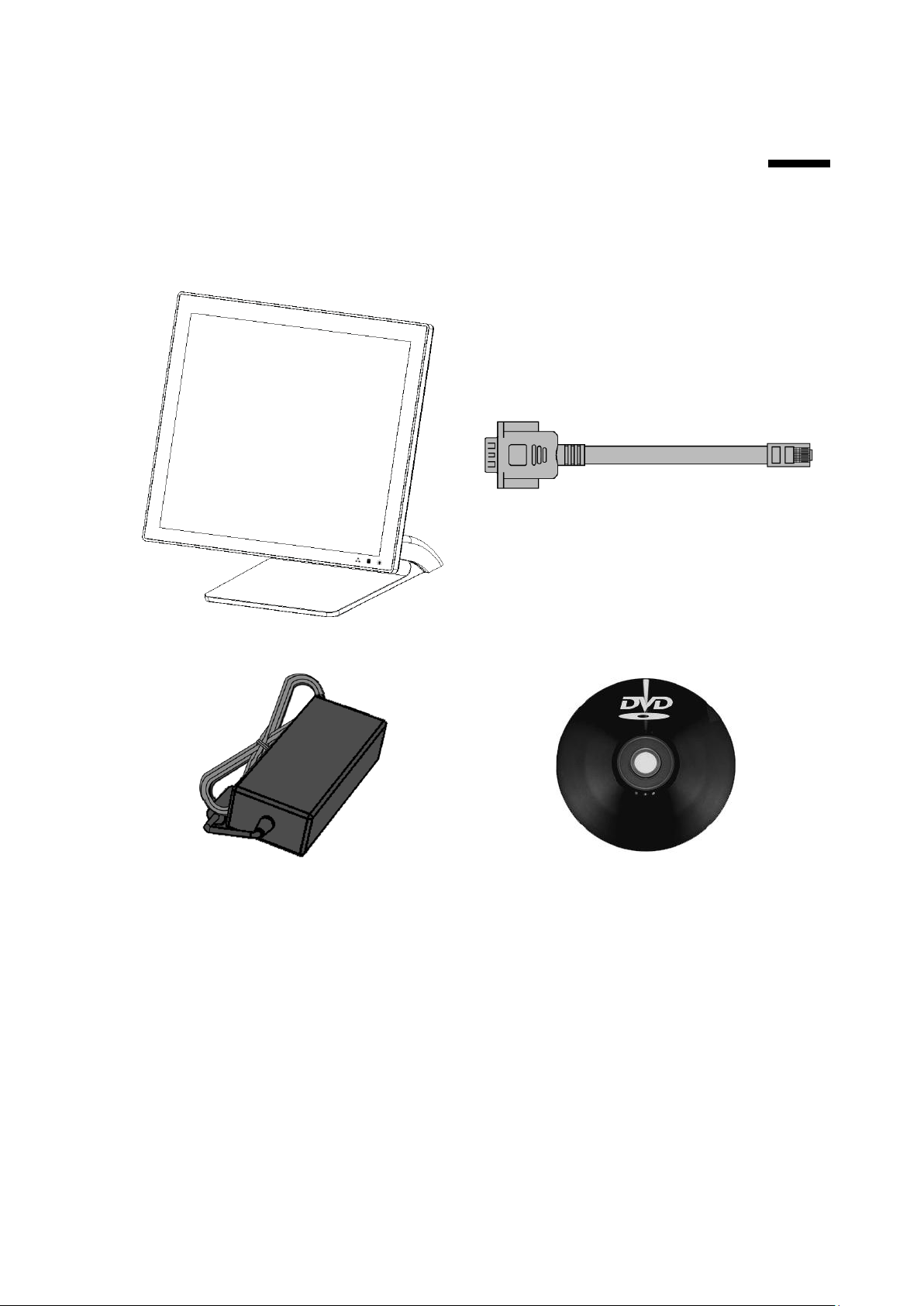
1. Device X 1
2. RJ50 to DB9 COM port adapter cable X 2
3. Power Adapter X 1
4. Manual DVD X 1
1. Hardware Setup
1.1. Packing Contents
1. 1.

5
The Power indicator will glow green when power is on.
The Storage indicator will blink green when the SATA storage is accessed.
The LAN indicator will blink green when transferring data through the LAN.
1.2. Quick Tour
Front View
LED Indicator:
Back View
Notices For Non-wireless Product 34
6
A.
B.
C.
D.
E.
F.
G.
H.
I.
J.
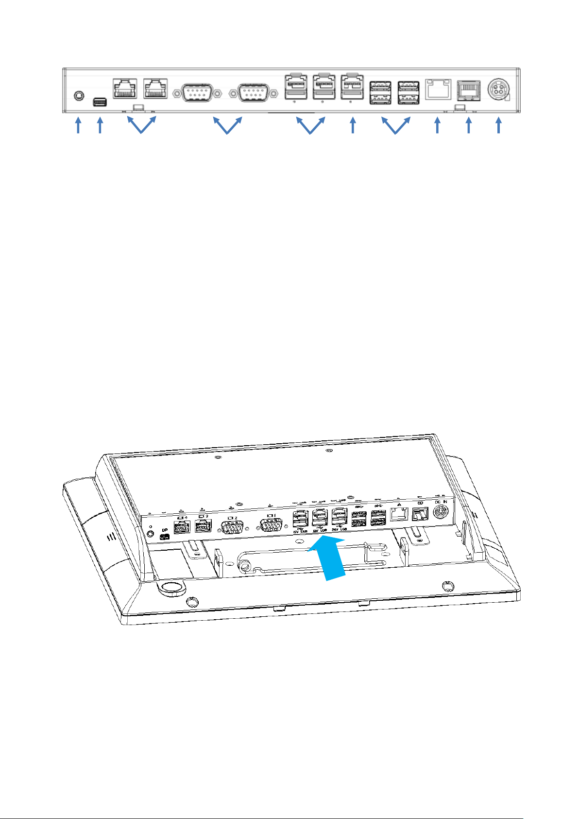
Back Panel I/O
I/O Functions:
A. 1 x 3.5mm Combo Audio jack
B. 1 x mini-DisplayPort
C. 2 x RS232 by RJ50 (COM4 / COM3), include RJ50 to DB9 convert cable
D. 2 x RS232 by DB-9 (COM2 / COM1)
E. 2 x 12V PoweredUSB
F. 1 x 24V PoweredUSB
G. 4 x USB3.0
H. 1 x Gigabit Ethernet (RJ-45)
I. 1 x Cash Drawer (RJ12)
J. 1 x 24VDC input, 4-pins jack
1.3. Basic Peripherals Installation
All cables and wires from peripherals to the Point Of Sale (POS) device are
recommended to connected as the direction as shown below.
7
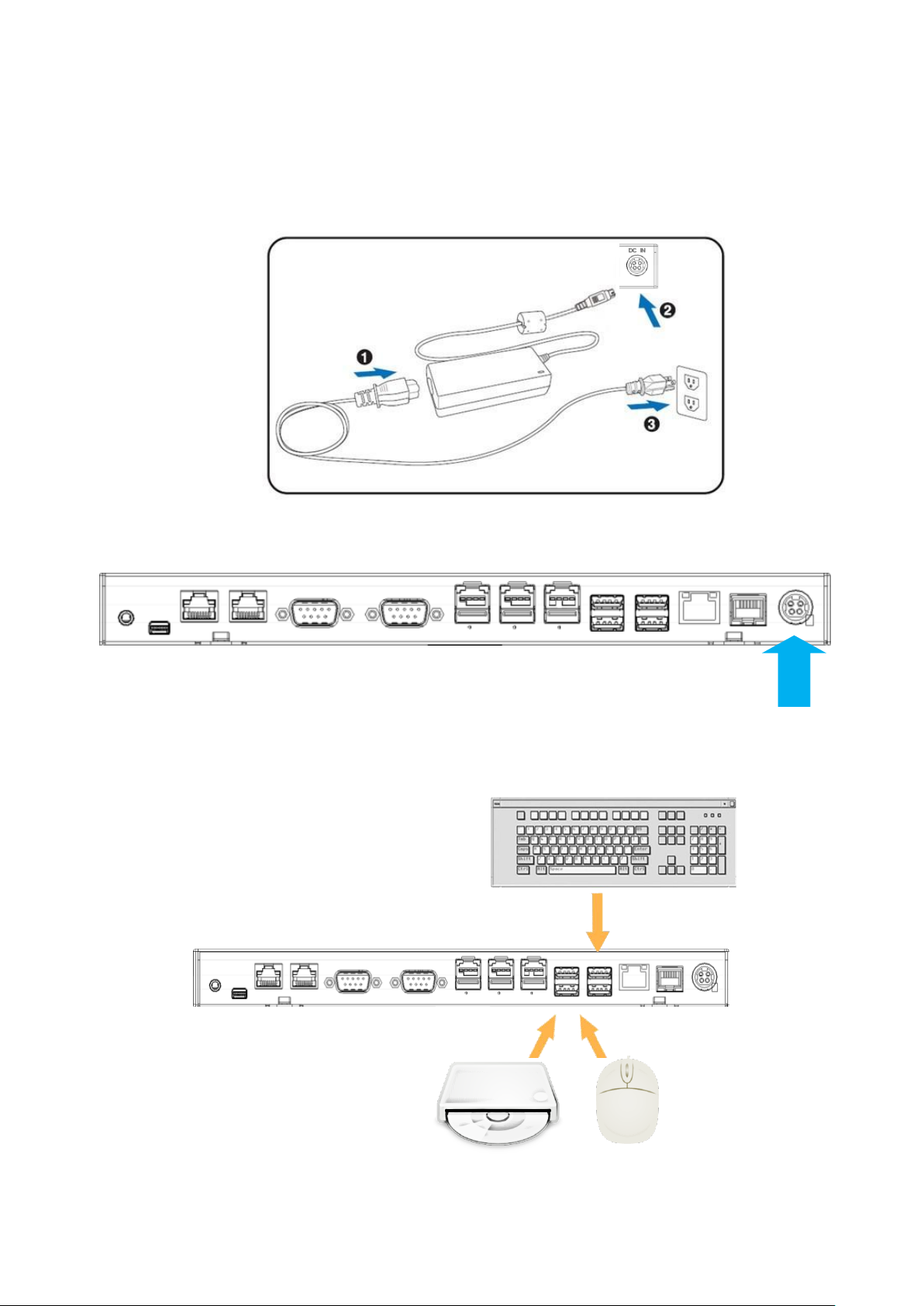
Power Adapter
Important!
Plug the AC adapter into the Point Of Sale (POS), and then connect to the
mains power supply.
Connect the 4-pin output jack of the adapter to the DC 24V jack on the back
panel of the device.
USB Mouse, USB Keyboard and USB Optical Disk Driver (ODD)
Connect your USB Mouse, USB Keyboard and USB Optical Disk Driver
(ODD) to USB ports on the back panel of the device.
Notices For Non-wireless Product 34

8
NOTE: The USB male length needs to be less than 57mm.
LAN Cable
Connect one end of RJ-45 LAN cable to the LAN port on the back panel of
the device, and the other end to your internet device.
Cash Drawer
Connect one end of RJ-12 cable to the Cash Drawer port on the back panel
of the device, and the other end to your cash drawer.
9
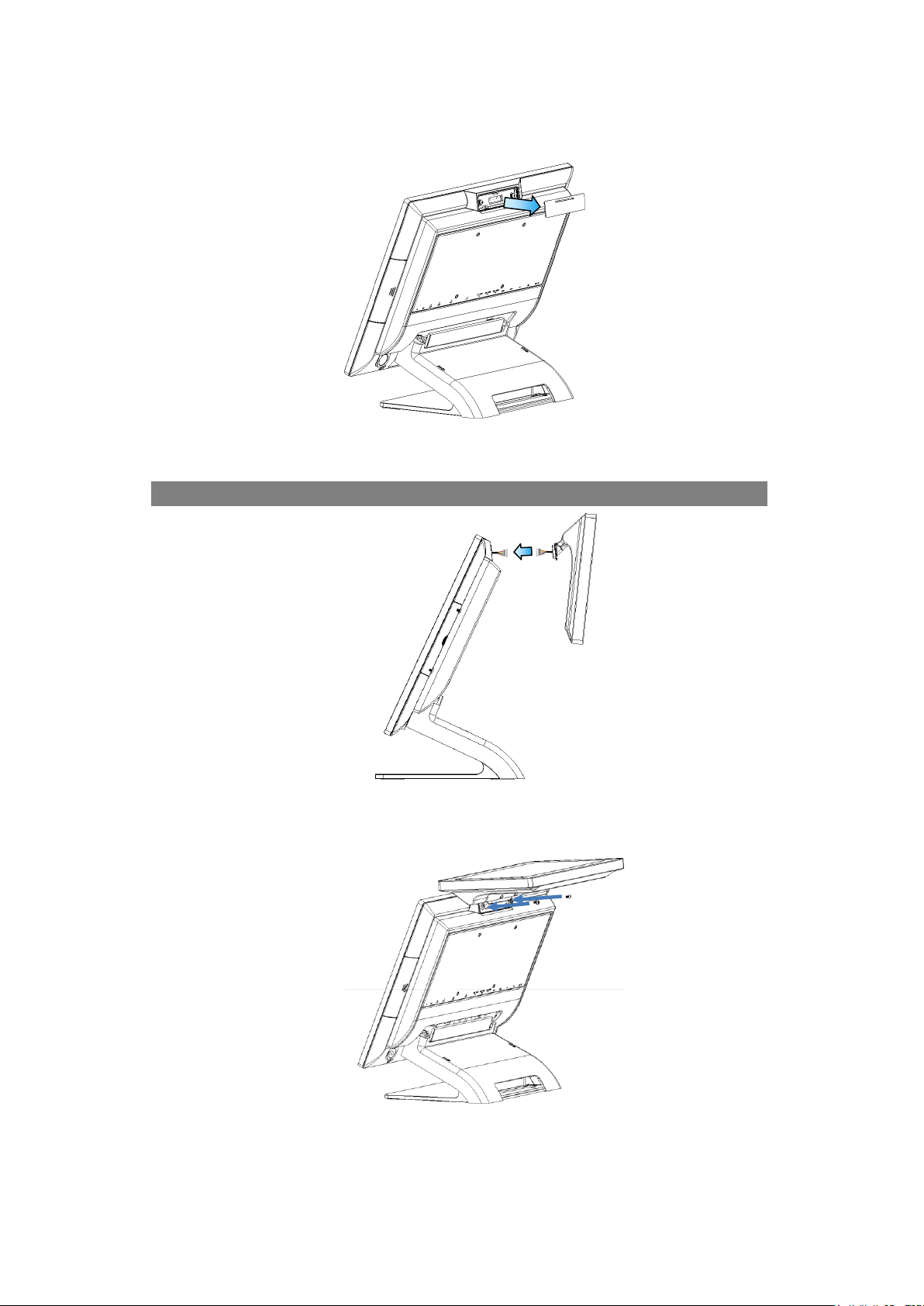
2nd Display
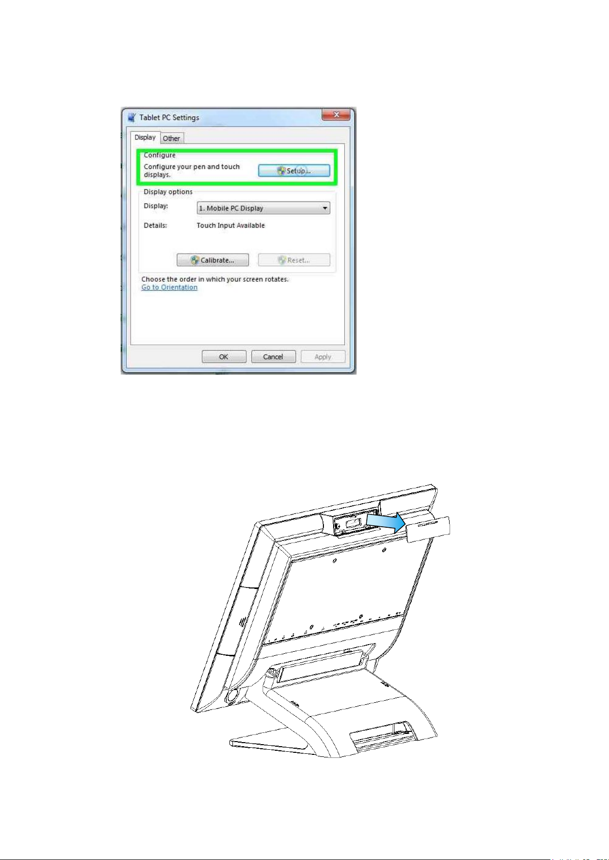
1. Remover the top peripheral mounting hole cover from the device and pull out
the connector from the device.
2. Adjust the hinge of the custom monitor (2nd display), and then connect to the
device as shown below.
NOTE: 2nd display cable need remove the connector cover first.
3. Mount the customer display to the device and tighten the two PHILLIPS M3
screws as shown below.
4. Please install 2nd display USB driver after device installation.
Please visit product web site and get driver: http://service.ebn.com.tw/tgcs
Notices For Non-wireless Product 34
10
5. For the current main display touch function work, you may need to perform
the following steps to correct the mapping. Run "Tablet PC Settings" on the
Windows Control Panel and click the "Settings" button.
Following the display instruction, manually touching the touch screen twice,
then the main touch will operate correctly on the main display.
Customer VFD
1. Remove the top peripheral mounting hole cover from the device and pull out
the connector from the device.

11
2. Adjust the hinge of the custom monitor (customer VFD), and then connect to
the device as shown below.
NOTE: VFD cable need remove the connector cover first.
3. Mount the customer display to the device and tighten the two PHILLIPS M3
screws as shown below.
4. Please install driver/utility after device installation.
Please visit product web site and get driver: http://service.ebn.com.tw/tgcs
Notices For Non-wireless Product 34

12
NOTE: MSR + iButton only can be installed on the right side.
MSR + iButton
1. Remove the right side peripheral cover from the system.
2. Install the adaptor.

13
3. Connect the cable of the MSR + iButton assembly to the system.
NOTE: MSR + iButton cable need remove the connector cover
4. Combine the MSR + iButton into side peripheral door of system, tighten the two
PHILLIPS M3 screws to fix the MSR assembly as shown below.
5. Please install driver/utility after device installation.
Please visit product web site and get driver: http://service.ebn.com.tw/tgcs
Notices For Non-wireless Product 34
 Loading...