

Toshiba 46TL868G Schematic
SERVICE MANUAL
LCD Color Television
Print this page
46TL868G
TOSHIBA WEB-ZEUS
Ver. 1.01
Updating history
Amendment by DS Company
Updating History,
2011-11-09 Amendment done by DS Company
>> terms and conditions >> privacy policy
Copyright © 1995-2011 TOSHIBA Corporation, All Rights Reserved.
5
6

Print this page
IMPORTANT NOTICE
WARNING:
You are requested that you shall not modify or alter the information or data provided herein without prior written consent by Toshiba. Toshiba shall not be liable to anybody for any damages, losses,
expenses or costs, if any, incurred in connection with or as a result of such modification or alteration.
THE INFORMATION OR DATA HEREIN SHALL BE PROVIDED "AS IS" WITHOUT ANY WARRANTY OF ANY KIND, EITHER EXPRESS OR IMPLIED WARRANTY OF MERCHANTABILITY AND FITNESS
FOR A PARTICULAR PURPOSE.
Toshiba shall not be liable for any damages, losses, expenses or costs, if any, incurred in connection with or as a result of use of any information or data provided herein.
TOSHIBA WEB-ZEUS
>> terms and conditions >> privacy policy
Copyright © 1995-2011 TOSHIBA Corporation, All Rights Reserved.

Print this page
GREEN PRODUCT PROCUREMENT
The EC is actively promoting the WEEE & RoHS Directives that define standards for recycling and reuse of Waste Electrical and Electronic Equipment and for the Restriction of the use of certain Hazardous
Substances. From July 1, 2006, the RoHS Directive will prohibit any marketing of new products containing the restricted substances.
Increasing attention is given to issues related to the global environmental. Toshiba Corporation recognizes environmental protection as a key management tasks, and is doing its utmost to enhance and improve the
quality and scope of its environmental activities. In line with this, Toshiba proactively promotes Green Procurement, and seeks to purchase and use products, parts and materials that have low environmental impacts.
Green procurement of parts is not only confined to manufacture. The same green parts used in manufacture must also be used as replacement parts.
TOSHIBA WEB-ZEUS
>> terms and conditions >> privacy policy
Copyright © 1995-2011 TOSHIBA Corporation, All Rights Reserved.

Print this page
LEAD-FREE SOLDER
This product is manufactured using lead-free solder as a part of a movement within the consumer products industry at large to be environmentally responsible. Lead-free solder must be used in the servicing and
repair of this product.
WARNING: This product is manufactured using lead free solder.
DO NOT USE LEAD BASED SOLDER TO REPAIR THIS PRODUCT!
The melting temperature of lead-free solder is higher than that of leaded solder by 86ºF to 104ºF (30ºC to 40ºC). Use of a soldering iron designed for lead-based solders to repair product made with lead-free solder
may result in damage to the component and or PCB being soldered. Great care should be made to ensure high-quality soldering when servicing this product especially when soldering large components, through-hole
pins, and on PCBs as the level of heat required to melt lead-free solder is high.
TOSHIBA WEB-ZEUS
>> terms and conditions >> privacy policy
Copyright © 1995-2011 TOSHIBA Corporation, All Rights Reserved.

Print this page
SAFETY INSTRUCTION
WARNING: BEFORE SERVICING THIS CHASSIS, READ THE "SAFETY PRECAUTION" AND "PRODUCT SAFETY NOTICE" INSTRUCTIONS BELOW.
Safety Precaution
WARNING: SERVICING SHOULD NOT BE ATTEMPTED BY ANYONE UNFAMILIAR WITH THE NECESSARY PRECAUTIONS ON THIS RECEIVER. THE FOLLOWING ARE THE NECESSARY
PRECAUTIONS TO BE OBSERVED BEFORE SERVICING THIS CHASSIS.
1. An isolation transformer should be connected in the power line between the receiver and the AC line before any service is performed on the receiver.
2. Always disconnect the power plug before any disassembling of the product. It may result in electrical shock.
3. When replacing a chassis in the cabinet, always be certain that all the protective devices are put back in place, such as nonmetallic control knobs, insulating covers, shields, isolation resistor-capacitor network,
etc.
4. Always keep tools, components of the product, etc away from the children, These items may cause injury to children.
5. Depending on the model, use an isolation transformer or wear suitable gloves when servicing with the power on, and disconnect the power plug to avoid electrical shock when replacing parts. In some cases,
alternating current is also impressed in the chassis, so electrical shock is possible if the chassis is contacted with the power on.
6. Always use the replacement parts specified for the particular model when making repairs. The parts used in products require special safety characteristics such as inflammability, voltage resistance, etc.
therefore, use only replacement parts that have these same characteristics. Use only the specified parts when the mark is indicated in the circuit diagram or parts list.
7. Parts mounting and routing dressing of wirings should be the same as that used originally. For safety purposes, insulating materials such as isolation tube or tape are sometimes used and printed circuit boards
are sometimes mounted floating. Also make sure that wirings is routed and clamped to avoid parts that generate heat and which use high voltage. Always follow the manufactured wiring routes / dressings.
8. Always ensure that all internal wirings are in accordance before re-assembling the external casing after a repairing completed. Do not allow internal wiring to be pinched by cabinets, panels, etc. Any error in
reassembly or wiring can result in electrical leakage, flame, etc., and may be hazardous.
9. NEVER remodel the product in any way. Remodeling can result in improper operation, malfunction, or electrical leakage and flame, which may be hazardous.
10. Touch current check. (After completing the work, measure touch current to prevent an electric shock.)
Plug the AC cord directly into the AC outlet. Do NOT use an isolation transformer for this check.
Connect a measuring network for touch currents between each exposed metallic part on the set and a good earth ground such as a water pipe.
Annex D
(normative)
Measuring network for TOUCH CURRENTS
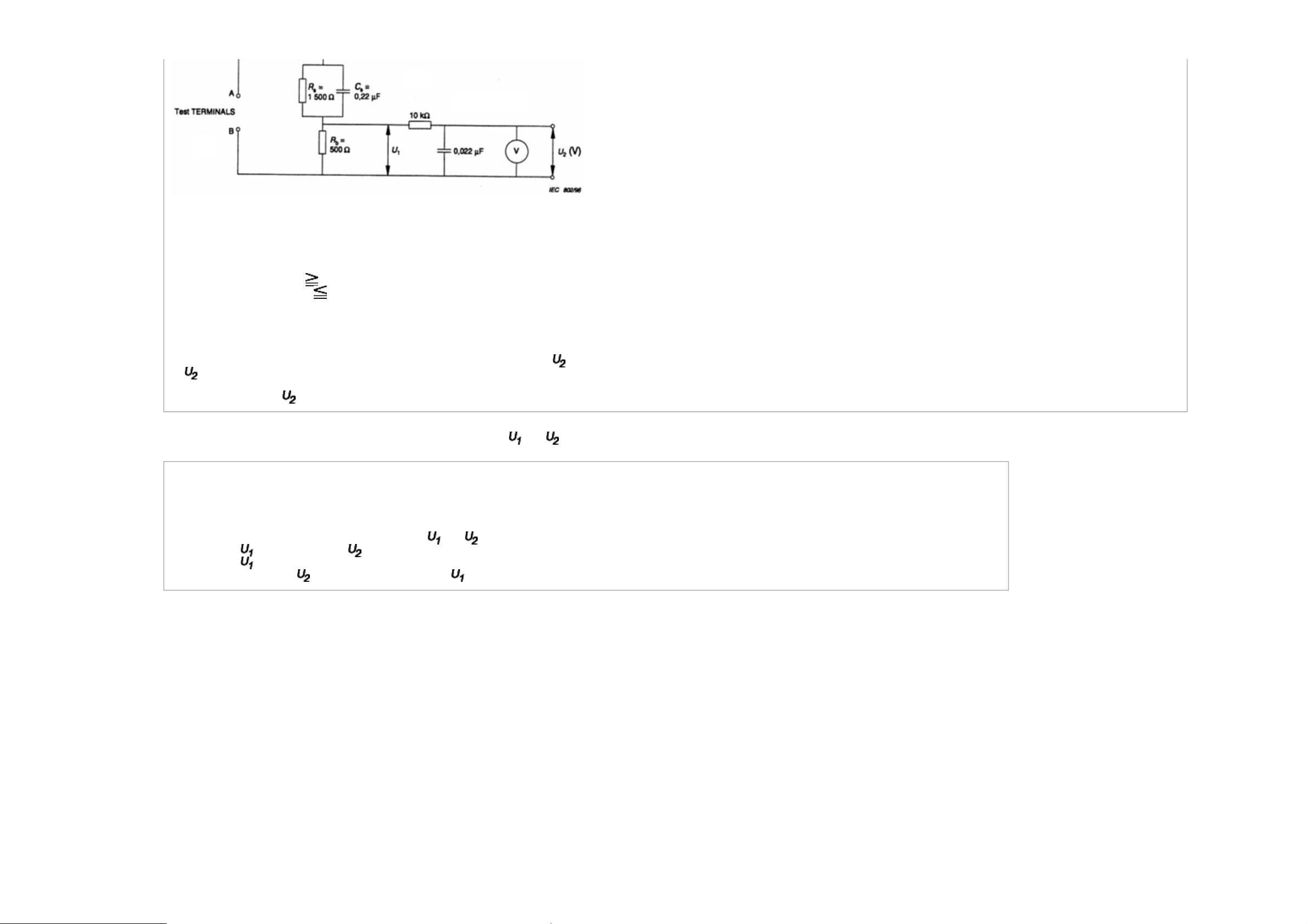
Resistance values in orms (Ω).
V: Voltmeter or oscilloscope
(r.m.s. or peak reading)
Input resistance : 1 MΩ
Input capacitance : 200 pF
Frequency range : 15 Hz to 1 MHz and d.c. respectively
Note: Appropriate measures should be taken to obtain the correct value in case of non sinusoidal waveforms.
The measuring instrument is calibrated by comparing the frequency factor of with the solid line in figure F.2 of IEC 60990 at various frequencies. A calibration curve is constructed showing the deviation
of from the ideal curve as a function of frequency.
TOUCH CURRENT = / 500 (peak value).
The potential at any point (TOUCH CURRENT) expressed as voltage and does not exceed the following value:
The part or contact of a TERMINAL is not HAZARDOUS LIVE if:
a) The open-circuit voltage should not exceed 35 V (peak) a.c. or 60 V d.c. or, if a) is not met.
b) The measurement of the TOUCH CURRENT shall be carried out in accordance with IEC 60990, with the measuring network described in Annex D of this standard.
The TOUCH CURRENT expressed as voltages and , does not exceed the following values:
- for a.c. : = 35 V (peak) and = 0.35 V (peak);
- for d.c. : = 1.0 V
Note: The limit values of = 0.35 V (peak) for a.c. and = 1.0 V for d.c. correspond to the values 0.7 mA (peak) a.c. and 2.0 mA d.c.
TOSHIBA WEB-ZEUS
>> terms and conditions >> privacy policy
Copyright © 1995-2011 TOSHIBA Corporation, All Rights Reserved.

Print this page
SAFETY INSTRUCTION
Product Safety Notice
Many electrical and mechanical parts in this chassis have special safety-related characteristics. These characteristics are often passed unnoticed by a visual inspection and the protection afforded by them cannot
necessarily be obtained by using replacement components rated for higher voltage, wattage, etc. Replacement parts which have these special safety characteristics are identified in this manual and its supplements;
electrical components having such features are identified by the international hazard symbols on the schematic diagram and the parts list.
Before replacing any of these components, read the parts list in this manual carefully. The use of substitute replacement parts which do not have the same safety characteristics as specified in the parts list may create
electrical shock, fire, or other hazards.
TOSHIBA WEB-ZEUS
>> terms and conditions >> privacy policy
Copyright © 1995-2011 TOSHIBA Corporation, All Rights Reserved.
Print this page
SAFETY INSTRUCTION
Handling the LCD Module
Safety Precaution
In the event that the screen is damaged or the liquid crystal (fluid) leaks, do not breathe in or drink this fluid.
Also, never touch this fluid. Such actions could cause toxicity or skin irritation. If this fluid should enter the mouth, rinse the mouth thoroughly with water. If the fluid should contact the skin or clothing, wipe off with
alcohol, etc., and rinse thoroughly with water. If the fluid should enter the eyes, immediately rinse the eyes thoroughly with running water.
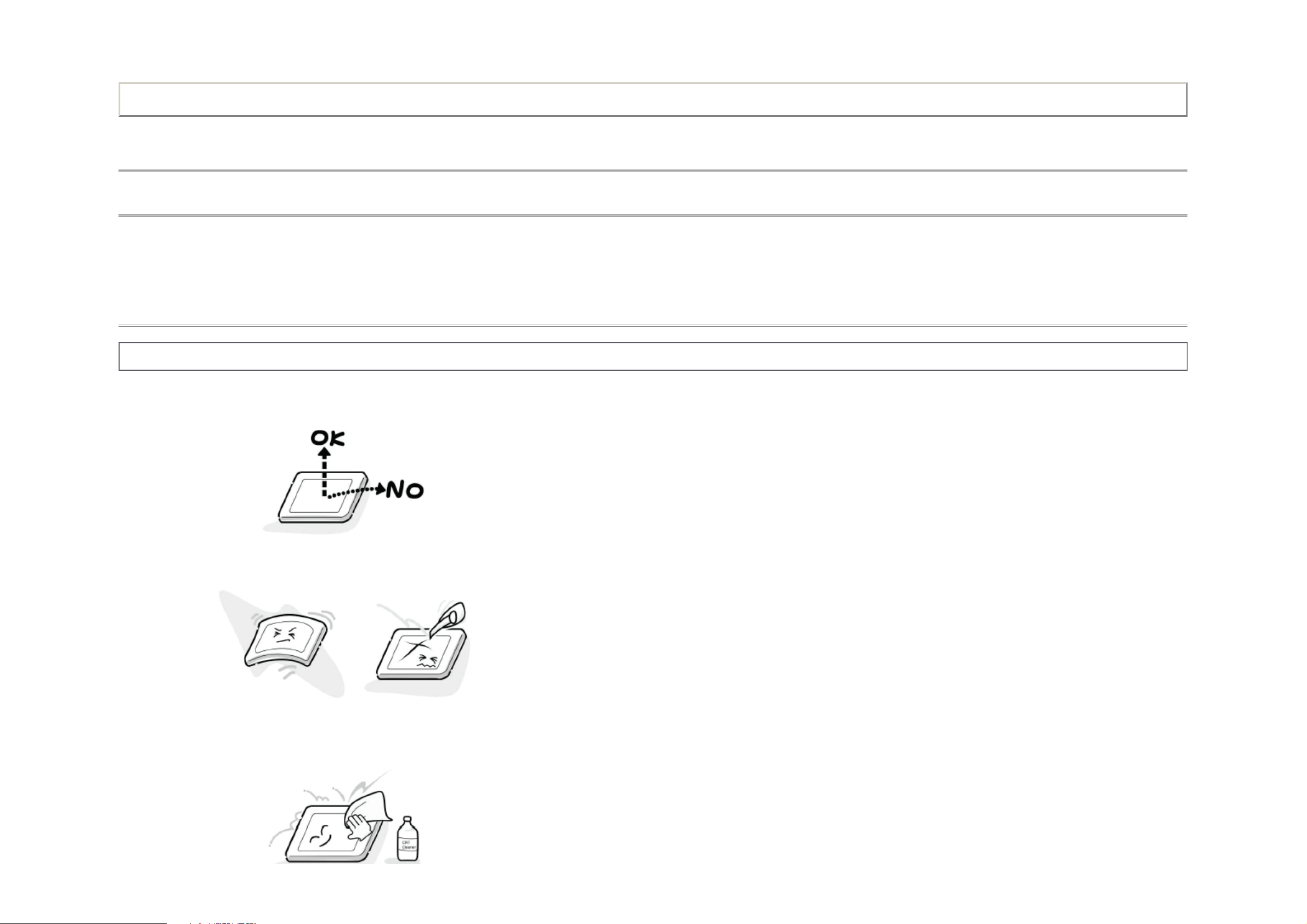
Precautions for Handling the LCD Module
CAUTION: The metal edges of the LCD module are sharp, handle it with care.
The LCD module can easily be damaged during disassembly or reassembly; therefore, always observe the following precautions when handling the module.
1. When attaching the LCD module to the LCD cover, position it appropriately and fasten at the position where the display can be viewed most conveniently.
2. Carefully align the holes at all four corners of the LCD module with the corresponding holes in the LCD cover and fasten with screws. Do not strongly push on the module because any impact can adversely
affect the performance. Also use caution when handling the polarized screen because it can easily be damaged.
3. If the panel surface becomes soiled, wipe with cotton or a soft cloth. If this does not remove the soiling, breathe on the surface and then wipe again.
If the panel surface is extremely solied, use a CRT cleaner as a cleaner. Wipe off the panel surface by drop the cleaner on the cloth. Do not drop the cleaner on the panel. Pay attention not to scratch the panel
surface.
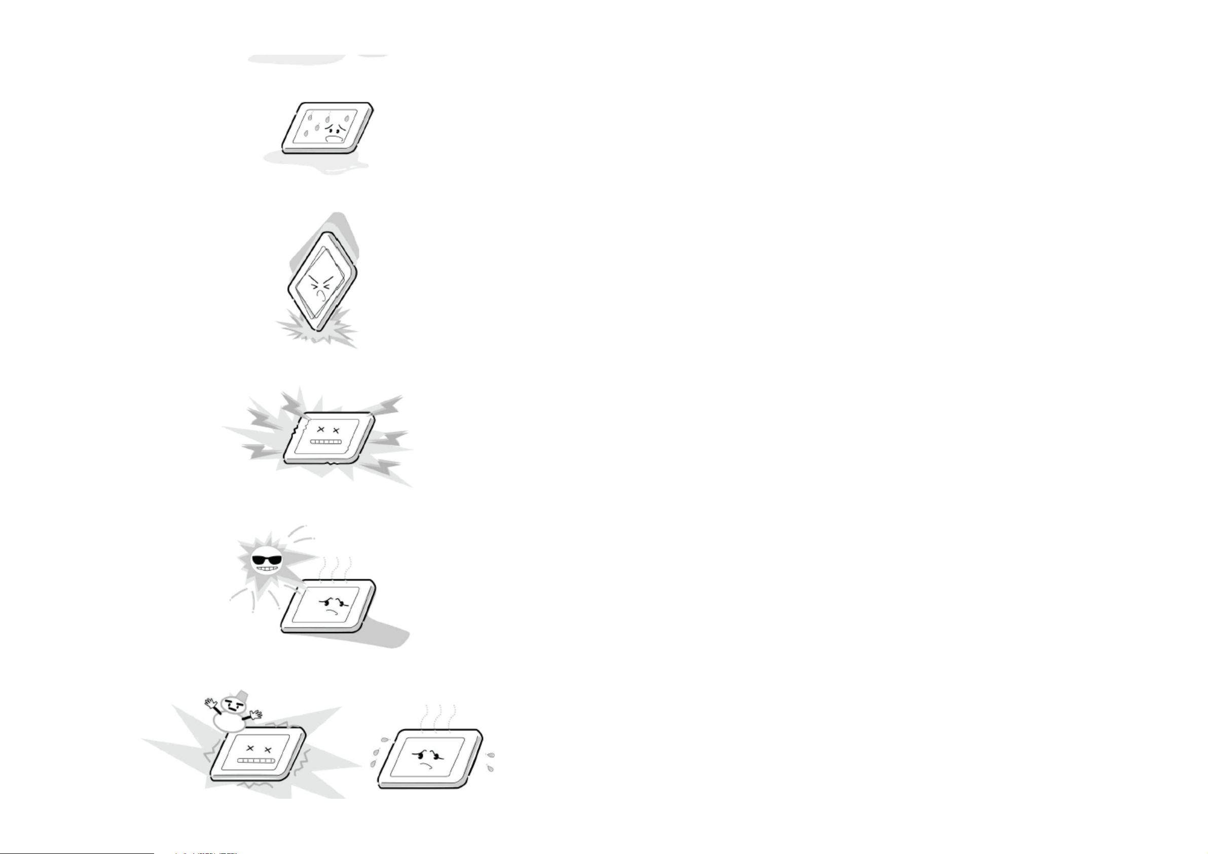
4. Leaving water or other fluids on the panel screen for an extended period of time can result in discoloration or stripes. Immediately remove any type of fluid from the screen.
5. Glass is used in the panel, so do not drop or strike with hard objects. Such actions can damage the panel.
6. CMOS-LSI circuitry is used in the LCD module, so avoid damage due to static electricity. When handling the module, use a wrist ground or anchor ground.
7. Do not expose the LCD module to direct sunlight or strong ultraviolet rays for an extended period of time.
8. Do not store the LCD module below the temperature conditions described in the specifications. Failure to do so could result in freezing of the liquid crystal due to cold air or loss of resilience or other damage.

9. Do not disassemble the LCD module. Such actions could result in improper operation.
10. When transporting the LCD module, do not use packing containing epoxy resin (amine) or silicon resin (alcohol or oxim). The gas generated by these materials can cause loss of polarity.
TOSHIBA WEB-ZEUS
>> terms and conditions >> privacy policy
Copyright © 1995-2011 TOSHIBA Corporation, All Rights Reserved.
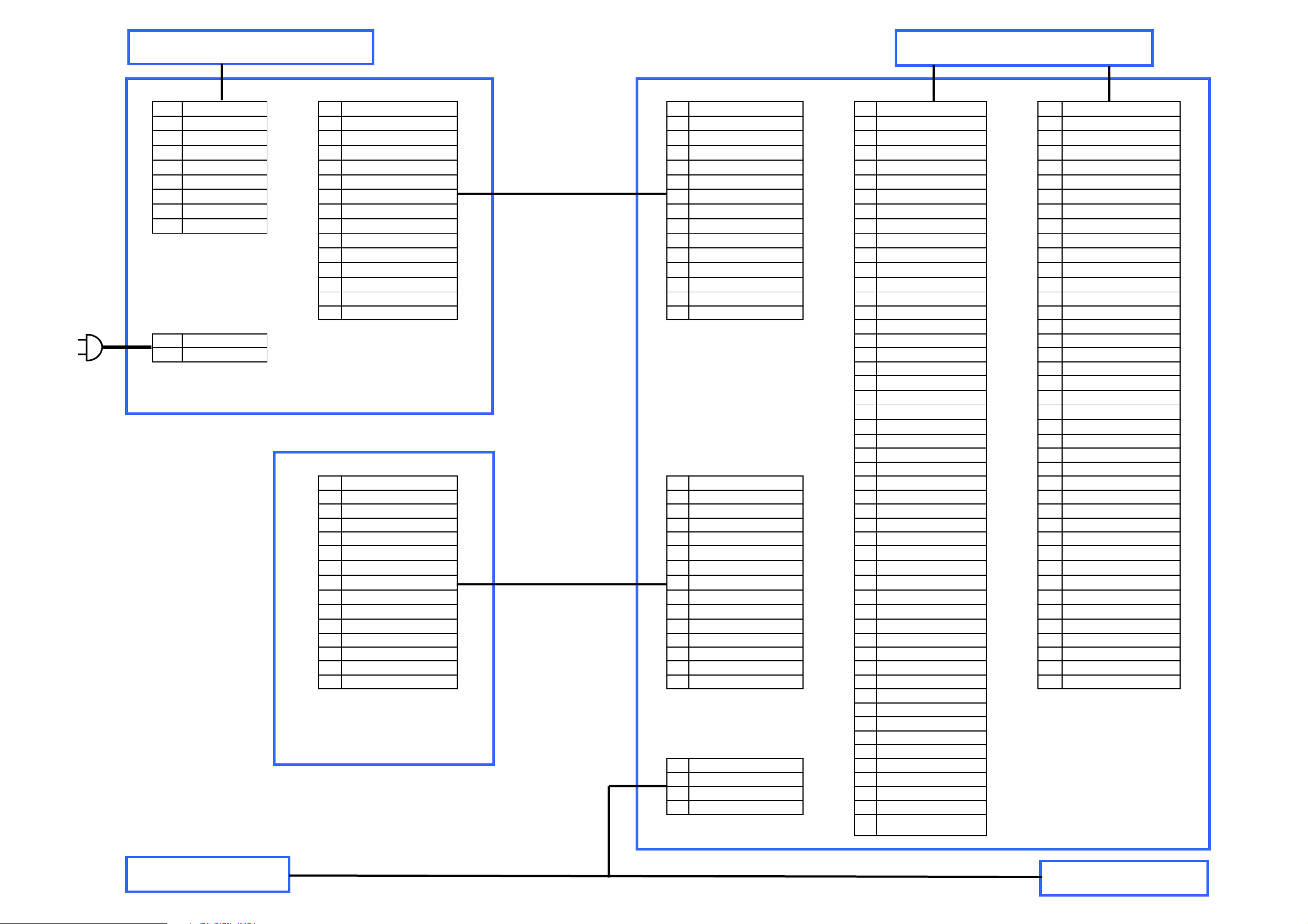
PJ860 PJ90 CN90 CN650 CN651
9 24V_LED 1 12V 1 12V 1 NC 1 NC
8 24V_LED 2 12V 2 12V 2 NC 2 NC
7 24V_LED 3 GND 3 GND 3 3D-GLASSES 3 GND
6 GND_LED 4 GND 4 GND 4 L/R_SW 4 TD4+
5 GND_LED 5 24V_Audio 5 24V_Audio 5 NC 5 TD44 GND_LED 6 GND_Audio 6 GND_Audio 6 NC 6 TD3+
3 BL_ONOFF 7 (24V_LNB) 7 (24V_LNB) 7 NC/LVDS_SEL 7 TD32 NC 8 GND 8 GND 8 NC 8 GND
1 PWM 9 5V-1 9 5V-1 9 NC 9 TDCLK+
10 AC_DETECT 10 AC_DETECT 10 2D/3D 10 TDCLK11 POWER_TV 11 POWER_TV 11 NC 11 GND
12 POWER_SIG 12 POWER_SIG 12 NC 12 TD2+
13 BL-ONOFF 13 BL-ONOFF 13 GND 13 TD214 3D-CONTROL 14 3D-CONTROL 14 TB4+ 14 TD1+
15 PWM 15 PWM 15 TB4- 15 TD1-
P801A 16 TB3+ 16 TD0+
1 LINE 17 TB3- 17 TD02 NEUTRAL 18 GND 18 GND
19 TBCLK+ 19 TC4+
20 TBCLK- 20 TC421 GND 21 TC3+
22 TB2+ 22 TC323 TB2- 23 GND
24 TB1+ 24 TCCLK+
25 TB1- 25 TCCLK-
CN740 CN740 26 TBO+ 26 GND
1 RMT_IN 1 RMT_IN 27 TBO- 27 TC2+
2 GND 2 GND 28 GND 28 TC23 3.3VF 3 3.3VF 29 TA4+ 29 TC1+
4 3.3V_TVM 4 3.3V_TVM 30 TA4- 30 TC15 OP-IN 5 OP-IN 31 TA3+ 31 TC0+
6 GND 6 GND 32 TA3- 32 TC07 POWER_ON_LED 7 POWER_ON_LED 33 GND 33 GND
8 STANDBY LED 8 STANDBY LED 34 TACLK+ 34 GND
9 Program_Timer_R 9 Program_Timer_R 35 TACLK- 35 GND
10 Program_Timer_G 10 Program_Timer_G 36 GND 36 NC
11 GND 11 GND 37 TA2+ 37 12V_LCD(NC)
12 GND 12 GND 38 TA2- 38 12V_LCD(NC)
13 GND 13 GND 39 TA1+ 39 12V_LCD(NC)
14 3D-IROUT1 14 3D-IROUT1 40 TA1- 40 12V_LCD(NC)
15 3D-IROUT2 15 3D-IROUT2 41 TAO+ 41 12V_LCD(NC)
42 TAO43 GND
44 GND
45 GND
CN300 46 NC
1 R-AMP 47 Vcc_LCD
2 R+AMP 48 Vcc_LCD
3 L-AMP 49 Vcc_LCD
4 L+AMP 50 Vcc_LCD
51 Vcc_LCD
PANEL LED-DRIVE
PANEL T-CON
Speaker
Speaker
PE1000
Main Board
V71A00022900
Power Board
PE1003
LED/RMT/3DIR

TROUBLESHOOTING GUIDE
UNDER CONSTRUCTION
Note: Please check back in the future.
Print this page
TOSHIBA WEB-ZEUS
>> terms and conditions >> privacy policy
Copyright © 1995-2011 TOSHIBA Corporation, All Rights Reserved.
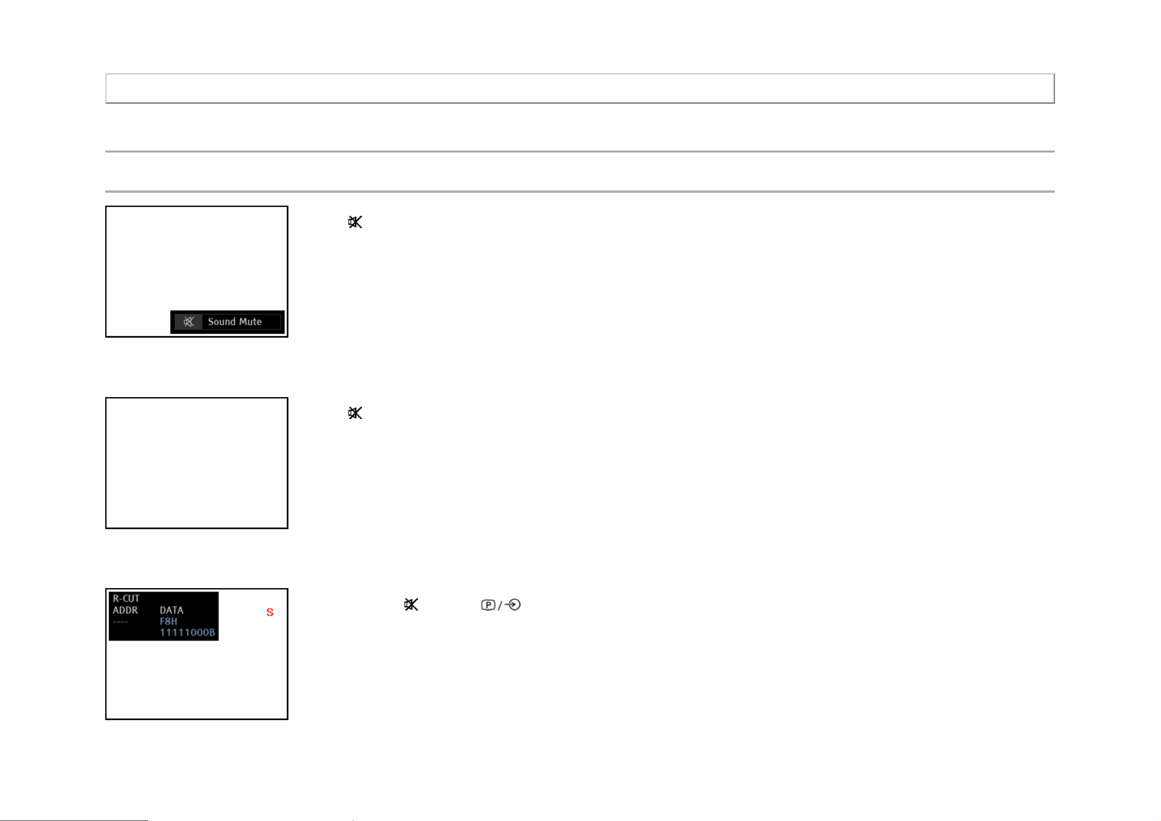
ADJUSTMENT
button on TV control panel.
Service Mode
Entering Service Mode
(Sound Mute display)
↓
Print this page
1. Press button once on Remote Control.
2. Press button again and keep pressing.
(Sound Mute display is canceled)
↓
(Service Mode display)
3. While pressing the button, press

TOSHIBA WEB-ZEUS
>> terms and conditions >> privacy policy
Copyright © 1995-2011 TOSHIBA Corporation, All Rights Reserved.
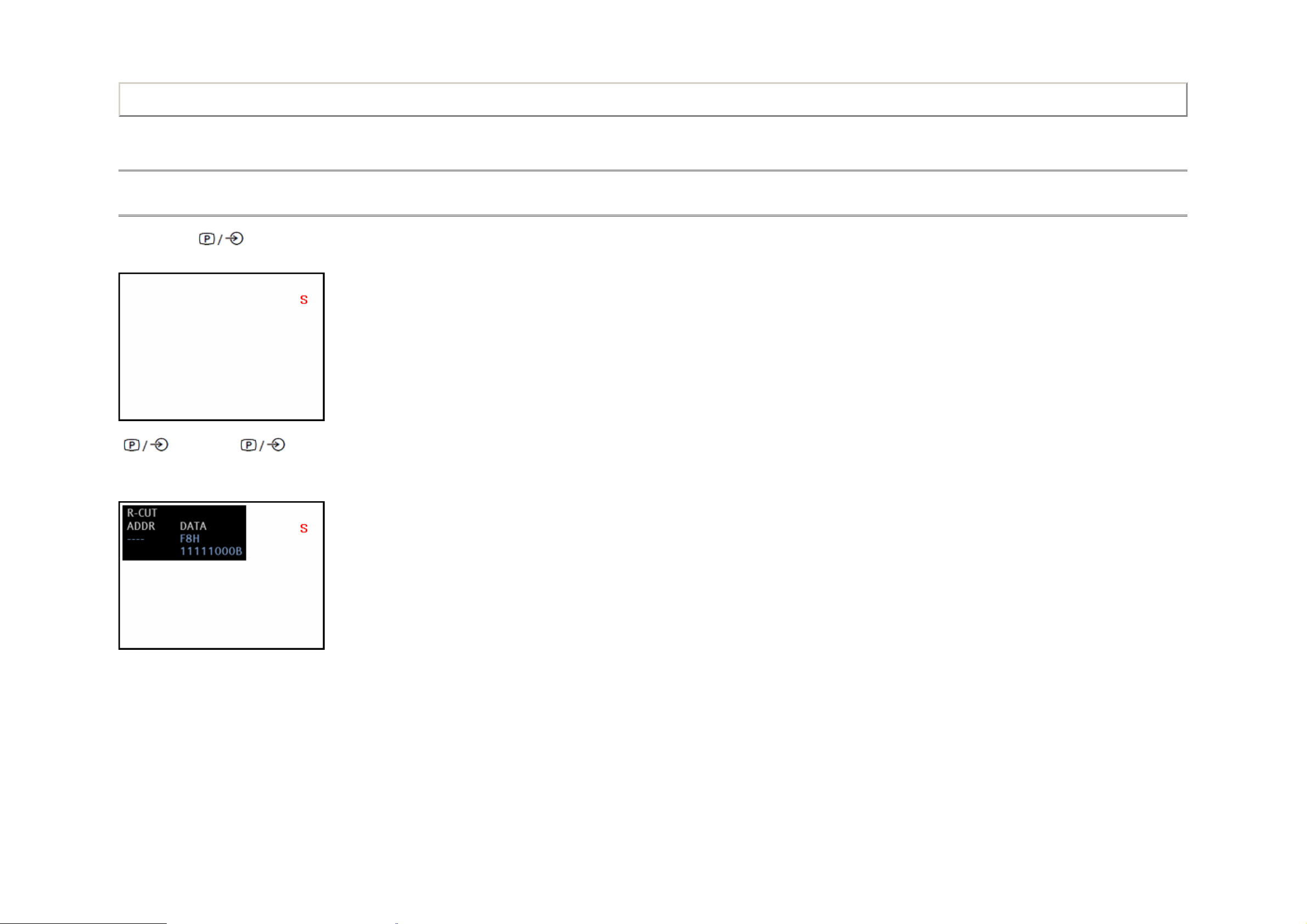
ADJUSTMENT
Service Mode
Displaying the Adjustment Menu
By pressing the button on TV control panel during Service Mode, Adjustment menu is switched off/on.
Adjustment menu = Off
Print this page
button
on control panel
Adjustment menu = ON
↑ ↓
on control panel
button
TOSHIBA WEB-ZEUS
>> terms and conditions >> privacy policy
Copyright © 1995-2011 TOSHIBA Corporation, All Rights Reserved.
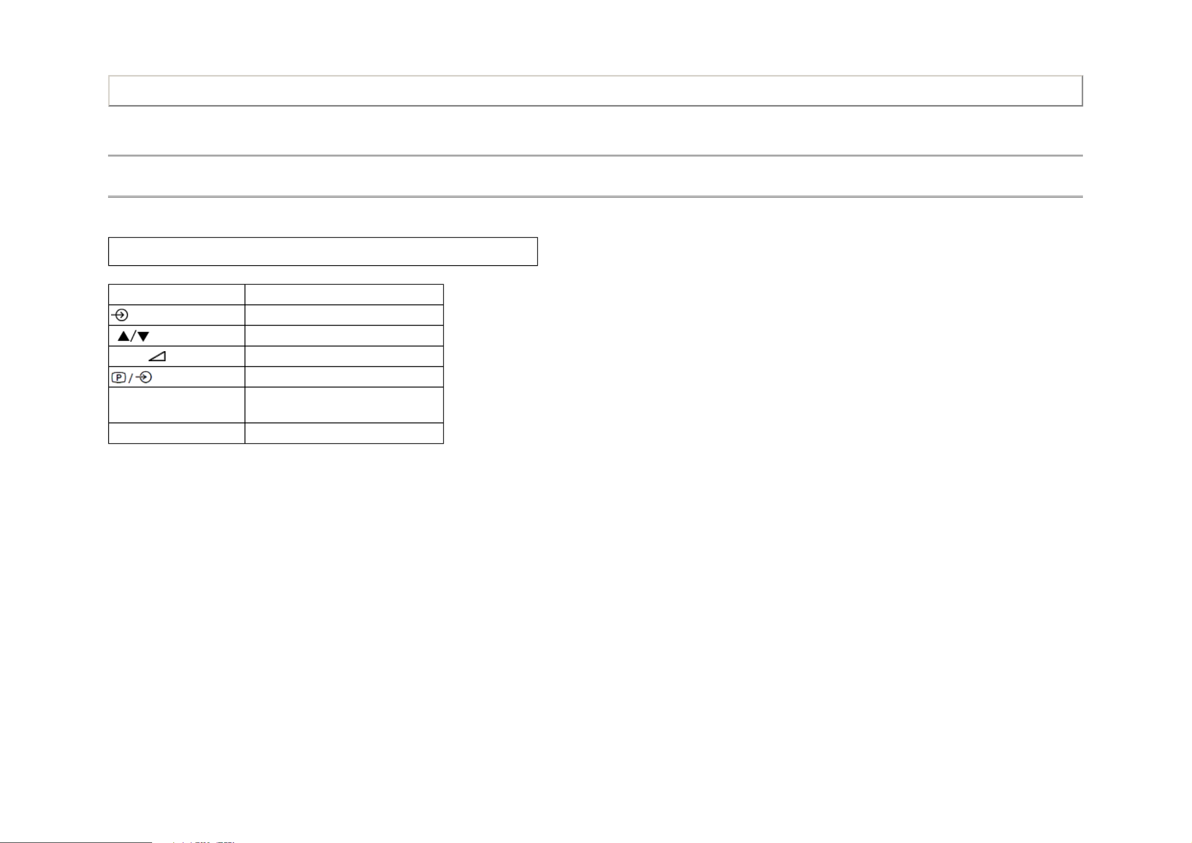
ADJUSTMENT
Service Mode
Key Function in the Service Mode
The following key entry during display of adjustment menu provides special functions.
CAUTION: Never try to perform initialization unless you have changed the memory IC.
Button Function
Print this page
button (on Remote)
P (on Remote)
Volume +/− (on Remote)
button (on TV)
7 button
Test signal selection
Selection of the adjustment items
Change of the data value
Adjustment menu ON/OFF
Automatic A/D Adjustment
(PC, Component, Composite(PAL, NTSC))
9 button Self Check display ON/OFF
TOSHIBA WEB-ZEUS
>> terms and conditions >> privacy policy
Copyright © 1995-2011 TOSHIBA Corporation, All Rights Reserved.

ADJUSTMENT
Service Mode
Selecting the Adjusting Items
While displaying the adjustment menu, press the P button to cycle through the adjustment items in the order of table. (P button for reverse order)
Print this page
TOSHIBA WEB-ZEUS
>> terms and conditions >> privacy policy
Copyright © 1995-2011 TOSHIBA Corporation, All Rights Reserved.
ADJUSTMENT
Service Mode
Adjusting the Data
While displaying the adjustment menu, press the VOLUME +/− button to change the value of data in the range from 00H to FFH. The variable range depends on the adjusting item.
Print this page
TOSHIBA WEB-ZEUS
>> terms and conditions >> privacy policy
Copyright © 1995-2011 TOSHIBA Corporation, All Rights Reserved.

ADJUSTMENT
Service Mode
Exit from Service Mode
Press the POWER button once to turn off the TV.
Print this page
TOSHIBA WEB-ZEUS
>> terms and conditions >> privacy policy
Copyright © 1995-2011 TOSHIBA Corporation, All Rights Reserved.
ADJUSTMENT
Service Mode
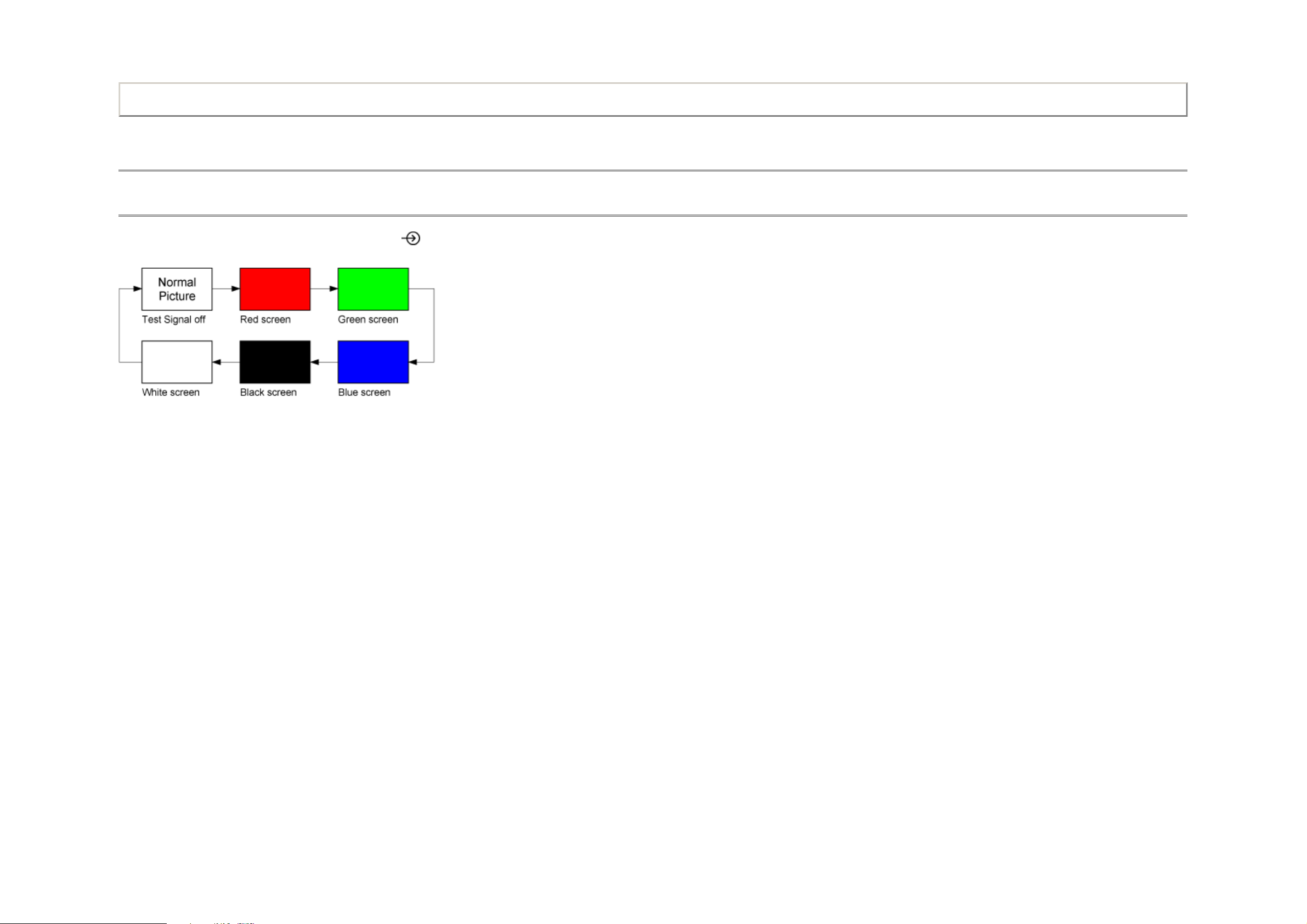
Test Signal Selection
While displaying the adjustment menu, every pressing of button on the Remote Control changes the built-in test patterns on screen as described below.
Print this page
TOSHIBA WEB-ZEUS
>> terms and conditions >> privacy policy
Copyright © 1995-2011 TOSHIBA Corporation, All Rights Reserved.
ADJUSTMENT
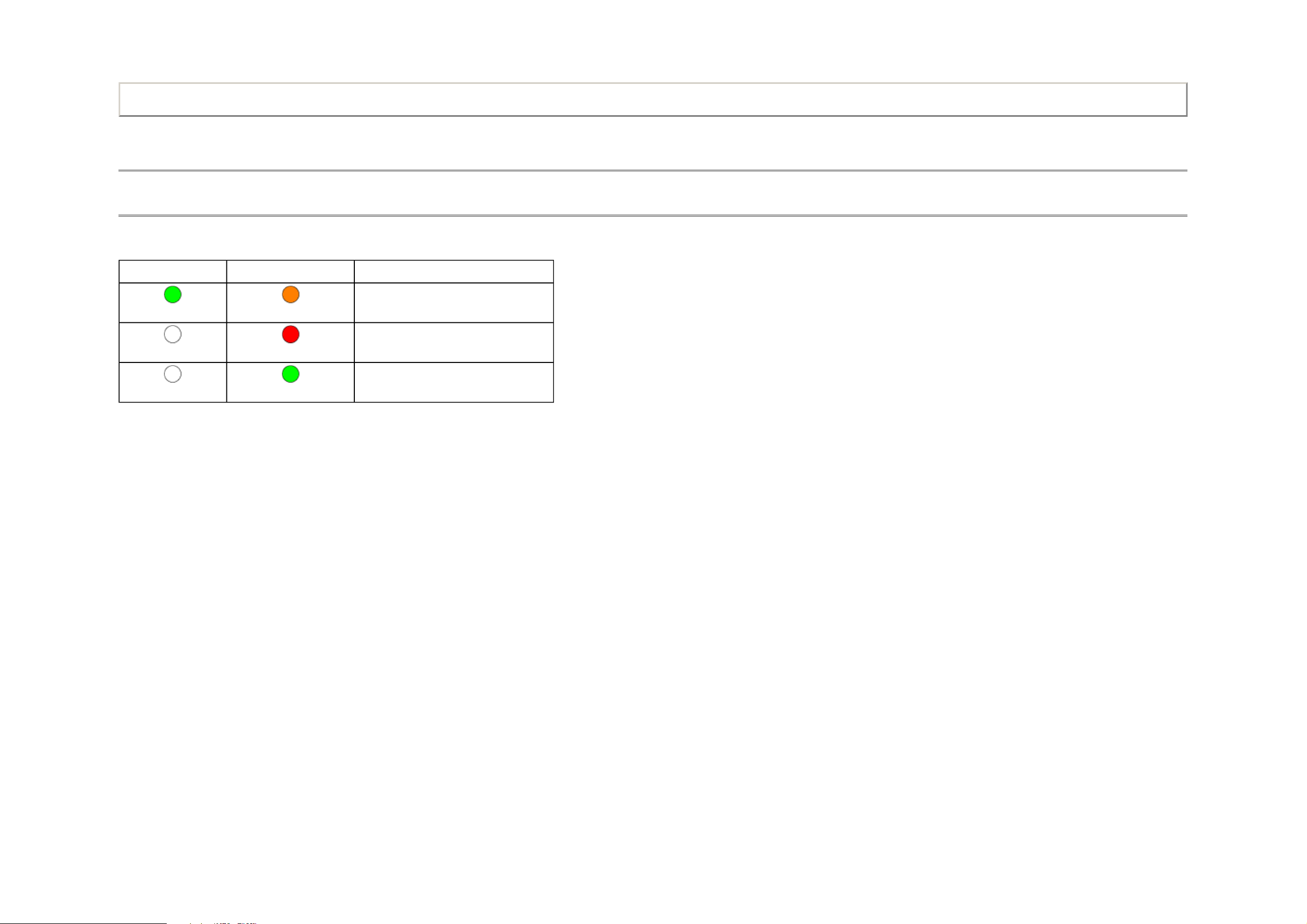
For Service SW Upgrade in Successful
Service Mode
LED Indications
SW Upgrade and Error conditions indicated by the PowerOn/Standby and ProgrammeTimer LEDs are described below.
ProgramTimer LED PowerOn/Standby LED
Green
Off
Orange
Red
For Service SW Upgrade in Progress
For Service SW Upgrade in Failed
Print this page
Off
Green
Refer to the Owner's Manual about LED indications for general operations.
TOSHIBA WEB-ZEUS
>> terms and conditions >> privacy policy
Copyright © 1995-2011 TOSHIBA Corporation, All Rights Reserved.
ADJUSTMENT
Service Mode
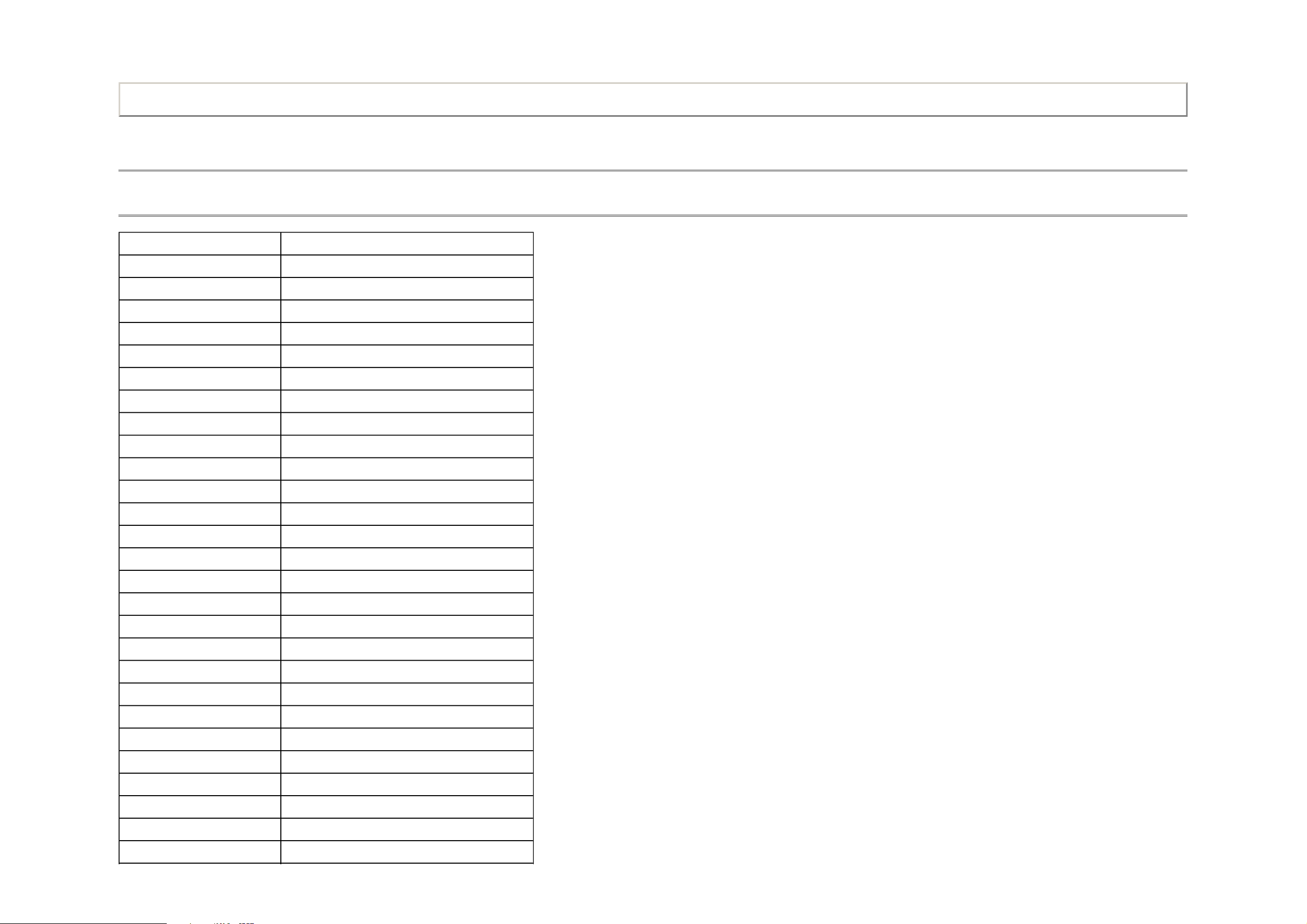
Adjusting Items in the Service Mode
Item Description
RCUT RED CUTOFF
GCUT GREEN CUTOFF
BCUT BLUE CUTOFF
RDRV RED DRIVE
GDRV GREEN DRIVE
BDRV BLUE DRIVE
Print this page
OSRC COOL R-CUTOFF-OFFSET for COOL
OSRC NATURAL R-CUTOFF-OFFSET for NATURAL
OSRC WARM R-CUTOFF-OFFSET for WARM
OSGC COOL G-CUTOFF-OFFSET for COOL
OSGC NATURAL G-CUTOFF-OFFSET for NATURAL
OSGC WARM G-CUTOFF-OFFSET for WARM
OSBC COOL B-CUTOFF-OFFSET for COOL
OSBC NATURAL B-CUTOFF-OFFSET for NATURAL
OSBC WARM B-CUTOFF-OFFSET for WARM
OSRD COOL R-DRIVE-OFFSET for COOL
OSRD NATURAL R-DRIVE-OFFSET for NATURAL
OSRD WARM R-DRIVE-OFFSET for WARM
OSGD COOL G-DRIVE-OFFSET for COOL
OSGD NATURAL G-DRIVE-OFFSET for NATURAL
OSGD WARM G-DRIVE-OFFSET for WARM
OSBD COOL B-DRIVE-OFFSET for COOL
OSBD NATURAL B-DRIVE-OFFSET for NATURAL
OSBD WARM B-DRIVE-OFFSET for WARM
OSRD 3D COOL R-DRIVE-OFFSET for COOL (3D)
OSRD 3D NATURAL R-DRIVE-OFFSET for NATURAL (3D)
OSRD 3D WARM R-DRIVE-OFFSET for WARM (3D)

OSGD 3D COOL G-DRIVE-OFFSET for COOL (3D)
BRTC HDMI PC DYNAMIC
BRIGHTNESS CENTER HDMI PC DYNAMIC
OSGD 3D NATURAL G-DRIVE-OFFSET for NATURAL (3D)
OSGD 3D WARM G-DRIVE-OFFSET for WARM (3D)
OSBD 3D COOL B-DRIVE-OFFSET for COOL (3D)
OSBD 3D NATURAL B-DRIVE-OFFSET for NATURAL (3D)
OSBD 3D WARM B-DRIVE-OFFSET for WARM (3D)
OPT1 OPTION DATA 1
OPT2 OPTION DATA 2
OPT3 OPTION DATA 3
OPT4 OPTION DATA 4
OPT5 OPTION DATA 5
OPT6 OPTION DATA 6
OPT7 OPTION DATA 7
OPT8 OPTION DATA 8
VOLUX VOLUM MAX
CNTX VIDEO CONTRAST MAX VIDEO
CNTX YPBPR HD CONTRAST MAX YPBPR HD
CNTX YPBPR SD CONTRAST MAX YPBPR SD
CNTX HDMI PC CONTRAST MAX HDMI PC
CNTX HDMI PC PC CONTRAST MAX HDMI PC PC
CNTX HDMI HD CONTRAST MAX HDMI HD
CNTX HDMI HD PC CONTRAST MAX HDMI HD PC
CNTX HDMI SD CONTRAST MAX HDMI SD
CNTX HDMI SD PC CONTRAST MAX HDMI SD PC
CNTX ATV CONTRAST MAX ATV
CNTX DTV CONTRAST MAX DTV
BRTC VIDEO DYNAMIC BRIGHTNESS CENTER VIDEO DYNAMIC
BRTC VIDEO STANDARD BRIGHTNESS CENTER VIDEO STANDARD
BRTC VIDEO MOVIE BRIGHTNESS CENTER VIDEO MOVIE
BRTC YPBPR HD DYNAMIC BRIGHTNESS CENTER YPBPR HD DYNAMIC
BRTC YPBPR HD STANDARD BRIGHTNESS CENTER YPBPR HD STANDARD
BRTC YPBPR HD MOVIE BRIGHTNESS CENTER YPBPR HD MOVIE
BRTC YPBPR SD DYNAMIC BRIGHTNESS CENTER YPBPR SD DYNAMIC
BRTC YPBPR SD STANDARD BRIGHTNESS CENTER YPBPR SD STANDARD
BRTC YPBPR SD MOVIE BRIGHTNESS CENTER YPBPR SD MOVIE

BRTC HDMI PC DYNAMIC
BRIGHTNESS CENTER HDMI PC DYNAMIC
BRTC HDMI PC STANDARD BRIGHTNESS CENTER HDMI PC STANDARD
BRTC HDMI PC MOVIE BRIGHTNESS CENTER HDMI PC MOVIE
BRTC HDMI PC PC BRIGHTNESS CENTER HDMI PC PC
BRTC HDMI HD DYNAMIC BRIGHTNESS CENTER HDMI HD DYNAMIC
BRTC HDMI HD STANDARD BRIGHTNESS CENTER HDMI HD STANDARD
BRTC HDMI HD MOVIE BRIGHTNESS CENTER HDMI HD MOVIE
BRTC HDMI HD PC BRIGHTNESS CENTER HDMI HD PC
BRTC HDMI SD DYNAMIC BRIGHTNESS CENTER HDMI SD DYNAMIC
BRTC HDMI SD STANDARD BRIGHTNESS CENTER HDMI SD STANDARD
BRTC HDMI SD MOVIE BRIGHTNESS CENTER HDMI SD MOVIE
BRTC HDMI SD PC BRIGHTNESS CENTER HDMI SD PC
BRTC ATV DYNAMIC BRIGHTNESS CENTER ATV DYNAMIC
BRTC ATV STANDARD BRIGHTNESS CENTER ATV STANDARD
BRTC ATV MOVIE BRIGHTNESS CENTER ATV MOVIE
BRTC DTV DYNAMIC BRIGHTNESS CENTER DTV DYNAMIC
BRTC DTV STANDARD BRIGHTNESS CENTER DTV STANDARD
BRTC DTV MOVIE BRIGHTNESS CENTER DTV MOVIE
COLC VIDEO DYNA COLOR CENTER VIDEO DYNA
COLC VIDEO STANDARD COLOR CENTER VIDEO STANDARD
COLC VIDEO MOVIE COLOR CENTER VIDEO MOVIE
COLC YPBPR HD DYNAMIC COLOR CENTER YPBPR HD DYNAMIC
COLC YPBPR HD STANDARD COLOR CENTER YPBPR HD STANDARD
COLC YPBPR HD MOVIE COLOR CENTER YPBPR HD MOVIE
COLC YPBPR SD DYNAMIC COLOR CENTER YPBPR SD DYNAMIC
COLC YPBPR SD STANDARD COLOR CENTER YPBPR SD STANDARD
COLC YPBPR SD MOVIE COLOR CENTER YPBPR SD MOVIE
COLC PC DYNAMIC COLOR CENTER PC DYNAMIC
COLC PC STANDARD COLOR CENTER PC STANDARD
COLC PC MOVIE COLOR CENTER PC MOVIE
COLC PC PC COLOR CENTER PC PC
COLC HDMI HD DYNAMIC COLOR CENTER HDMI HD DYNAMIC
COLC HDMI HD STANDARD COLOR CENTER HDMI HD STANDARD
COLC HDMI HD MOVIE COLOR CENTER HDMI HD MOVIE
COLC HDMI HD PC COLOR CENTER HDMI HD PC
COLC HDMI SD DYNAMIC COLOR CENTER HDMI SD DYNAMIC

COLC HDMI SD STANDARD
COLOR CENTER HDMI SD STANDARD
COLC HDMI SD MOVIE COLOR CENTER HDMI SD MOVIE
COLC HDMI SD PC COLOR CENTER HDMI SD PC
COLC ATV DYNAMIC COLOR CENTER ATV DYNAMIC
COLC ATV STANDARD COLOR CENTER ATV STANDARD
COLC ATV MOVIE COLOR CENTER ATV MOVIE
COLC DTV DYNAMIC COLOR CENTER DTV DYNAMIC
COLC DTV STANDARD COLOR CENTER DTV STANDARD
COLC DTV MOVIE COLOR CENTER DTV MOVIE
UVTT VIDEO DYNAMIC TINT CENTER VIDEO DYNAMIC
UVTT VIDEO STANDARD TINT CENTER VIDEO STANDARD
UVTT VIDEO MOVIE TINT CENTER VIDEO MOVIE
UVTT YPBPR HD DYNAMIC TINT CENTER YPBPR HD DYNAMIC
UVTT YPBPR HD STANDARD TINT CENTER YPBPR HD STANDARD
UVTT YPBPR HD MOVIE TINT CENTER YPBPR HD MOVIE
UVTT YPBPR SD DYNAMIC TINT CENTER YPBPR SD DYNAMIC
UVTT YPBPR SD STANDARD TINT CENTER YPBPR SD STANDARD
UVTT YPBPR SD MOVIE TINT CENTER YPBPR SD MOVIE
UVTT HDMI PC DYNAMIC TINT CENTER HDMI PC DYNAMIC
UVTT HDMI PC STANDARD TINT CENTER HDMI PC STANDARD
UVTT HDMI PC MOVIE TINT CENTER HDMI PC MOVIE
UVTT HDMI PC PC TINT CENTER HDMI PC PC
UVTT HDMI HD DYNAMIC TINT CENTER HDMI HD DYNAMIC
UVTT HDMI HD STANDARD TINT CENTER HDMI HD STANDARD
UVTT HDMI HD MOVIE TINT CENTER HDMI HD MOVIE
UVTT HDMI HD PC TINT CENTER HDMI HD PC
UVTT HDMI SD DYNAMIC TINT CENTER HDMI SD DYNAMIC
UVTT HDMI SD STANDARD TINT CENTER HDMI SD STANDARD
UVTT HDMI SD MOVIE TINT CENTER HDMI SD MOVIE
UVTT HDMI SD PC TINT CENTER HDMI SD PC
UVTT ATV DYNAMIC TINT CENTER ATV DYNAMIC
UVTT ATV STANDARD TINT CENTER ATV STANDARD
UVTT ATV MOVIE TINT CENTER ATV MOVIE
UVTT DTV DYNAMIC TINT CENTER DTV DYNAMIC
UVTT DTV STANDARD TINT CENTER DTV STANDARD
UVTT DTV MOVIE TINT CENTER DTV MOVIE

SHPC VIDEO DYNAMIC SHARPNESS CENTER VIDEO DYNAMIC
SHPC VIDEO STANDARD SHARPNESS CENTER VIDEO STANDARD
SHPC VIDEO MOVIE SHARPNESS CENTER VIDEO MOVIE
SHPC YPBPR HD DYNAMIC SHARPNESS CENTER YPBPR HD DYNAMIC
SHPC YPBPR HD STANDARD SHARPNESS CENTER YPBPR HD STANDARD
SHPC YPBPR HD MOVIE SHARPNESS CENTER YPBPR HD MOVIE
SHPC YPBPR SD DYNAMIC SHARPNESS CENTER YPBPR SD DYNAMIC
SHPC YPBPR SD STANDARD SHARPNESS CENTER YPBPR SD STANDARD
SHPC YPBPR SD MOVIE SHARPNESS CENTER YPBPR SD MOVIE
SHPC HDMI PC DYNAMIC SHARPNESS CENTER HDMI PC DYNAMIC
SHPC HDMI PC STANDARD SHARPNESS CENTER HDMI PC STANDARD
SHPC HDMI PC MOVIE SHARPNESS CENTER HDMI PC MOVIE
SHPC HDMI PC PC SHARPNESS CENTER HDMI PC PC
SHPC HDMI HD DYNAMIC SHARPNESS CENTER HDMI HD DYNAMIC
SHPC HDMI HD STANDARD SHARPNESS CENTER HDMI HD STANDARD
SHPC HDMI HD MOVIE SHARPNESS CENTER HDMI HD MOVIE
SHPC HDMI HD PC SHARPNESS CENTER HDMI HD PC
SHPC HDMI SD DYNAMIC SHARPNESS CENTER HDMI SD DYNAMIC
SHPC HDMI SD STANDARD SHARPNESS CENTER HDMI SD STANDARD
SHPC HDMI SD MOVIE SHARPNESS CENTER HDMI SD MOVIE
SHPC HDMI SD PC SHARPNESS CENTER HDMI SD PC
SHPC ATV DYNAMIC SHARPNESS CENTER ATV DYNAMIC
SHPC ATV STANDARD SHARPNESS CENTER ATV STANDARD
SHPC ATV MOVIE SHARPNESS CENTER ATV MOVIE
SHPC DTV DYNAMIC SHARPNESS CENTER DTV DYNAMIC
SHPC DTV STANDARD SHARPNESS CENTER DTV STANDARD
SHPC DTV MOVIE SHARPNESS CENTER DTV MOVIE
TOSHIBA WEB-ZEUS
>> terms and conditions >> privacy policy
Copyright © 1995-2011 TOSHIBA Corporation, All Rights Reserved.
ADJUSTMENT
Service Mode
Convert from Bit (Binary) to Hex
The table for converting from bit (D7-D0) to hex (0x**)
BIT (Binary)
High nibble D7 D6 D5 D4
Low nibble D3 D2 D1 D0
HEX 0 0 0 0 0
1 0 0 0 1
2 0 0 1 0
Print this page
3 0 0 1 1
4 0 1 0 0
5 0 1 0 1
6 0 1 1 0
7 0 1 1 1
8 1 0 0 0
9 1 0 0 1
A 1 0 1 0
B 1 0 1 1
C 1 1 0 0
D 1 1 0 1
E 1 1 1 0
F 1 1 1 1
E.g. If Bit D7-0 = 0101 1010, Hex data is 0x5A.

TOSHIBA WEB-ZEUS
>> terms and conditions
>> privacy policy
Copyright © 1995-2011 TOSHIBA Corporation, All Rights Reserved.
ADJUSTMENT
A/D adjustment is set correctly.
A/D adjustment is not set correctly.
A/D adjustment is not needed because the picture format is not used.
A/D adjustment is set correctly.
A/D adjustment is not set correctly.
Service Mode
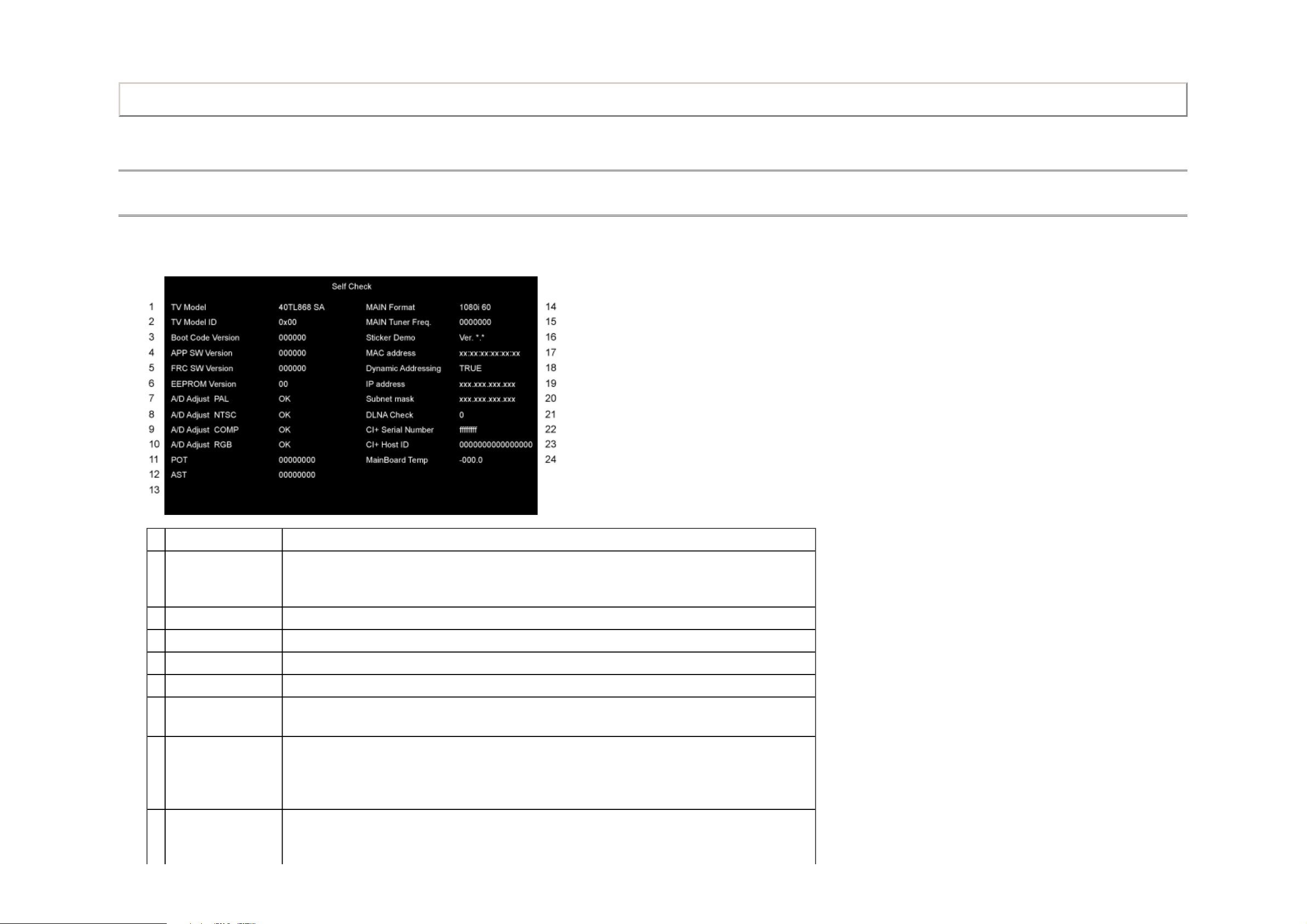
Self Check
1. "Self Check" screen is shown by pressing "9" button on Remote Control during display of Adjustment menu in the service mode.
2. The size of characters in "Self Check" screen should be same as the user menu.
Print this page
Item Explanation/Data Format
1 TV Model Model name and Panel vendor
SA : SAMSUNG AU : AUO SH:SHARP
LG : LGD CM:CMI
2 TV Model ID No function of this display.
3 Boot Code Version Version information of boot code.
4 APP SW Version Version information of Application SW.
5 FRC SW Version Version information of FRC SW.
6 EEPROM Version Version information of EEPROM data.
Display 1 byte data. (Hex)
7 A/D Adjust PAL A/D adjustment status for PAL signal
OK :
NG :
— :
8 A/D Adjust NTSC A/D adjustment status for NTSC signal
OK :
NG :

— :
A/D adjustment is not needed because the picture format is not used.
A/D adjustment is set correctly.
A/D adjustment is not set correctly.
A/D adjustment is not needed because the picture format is not used.
A/D adjustment is set correctly.
A/D adjustment is not set correctly.
A/D adjustment is not needed because the picture format is not used.
9 A/D Adjust COMP A/D adjustment status for Component input
OK :
NG :
— :
10 A/D Adjust RGB A/D adjustment status for SCART and PC input
OK :
NG :
— :
11 POT (Power On Time) Total time the TV has been powered on. (Unit: Hours) (Decimal)
Stand by mode (AC is on, but Panel is off) is not included.
The value is reset to 0 only when receiving the ship out code.
After power on, count up when 1 hour passed.
No need to memory the 0-59 minutes.
12 AST (AC Supply time) Total time the TV has been plugged in. (Unit: Hours) (Decimal)
Stand by mode (AC is on, but Panel is off) is included.
Others are same as POT
13 MAIN Format Video Format Information
14 MAIN Tuner Freq. Displays tuned frequency (Unit: kHz) (Decimal)
15 Sticker Demo Version information of Sticker Demo data
16 MAC address Media Access Control (MAC) address.
Display is in the format: xx:xx:xx:xx:xx:xx (Hex)
17 Dynamic Addressing Status of Dynamic Host Configuration Protocol (DHCP) Configuration.
TRUE: IP address will be automatically configured if the TV is connected to a network that supports DHCP
false : IP address must be manually set to a static IP address
18 IP address Current Internet Protocol (IP) address.
Display *.*.*.* format (* is decimal)
19 Subnet mask Current Subnet Mask.
Display *.*.*.* format (* is decimal)
20 DLNA Check Total Number of Successful DLNA factory tests. (Decimal)
21 CI+ Serial Number Serial Number of CI+ data
Display 4 byte data.(Hex)
22 CI+ Host ID Host ID of CI+
Display 8 byte data.(Hex)
23 MainBoard Temp Temperature of MainBoard
The value from temperature sensor.
Display -040.0−125.0 (Decimal)
 Loading...