

Page 1

FILE NO. 050-200234
SERVICE MANUAL
PLASMA DISPLAY MONITOR
42WP27B, 42WP27C
42WP27E, 42WP27F
42WP27R
PRINTED IN JAPAN Dec, 2002
Page 2
CONTENTS
Page Page
1 Applicable signals 3
2 Safety Precautions 4
2.1. General Guidelines
3 Prevention of Electro Static Discharge (ESD) to
Electrostatically Sensitive (ES) Devices 5
4 About lead free solder (PbF) 6
5 PCB Structure sheet of GP5D chassis 7
6 Service Hint 8
7 Location of Lead Wiring 9
8 Adjustment Procedure 10
8.1. +B Set-up 10
8.2. Driver Set-up 10
8.3. Initialization Pulse Adjust 11
8.4. P.C.B. (Printed Circuit Board) exchange 12
8.5. Adjustment Volume Location 12
8.6. Test Point Location 12
9 Service mode 13
9.1. CAT (computer Aided Test) mode
9.2. IIC mode structure (following items value is sample data.)
10 Alignment 16
10.1. Pedestal setting 16
10.2. NTSC panel white balance
10.3. PAL/SECAM panel white balance 18
10.4. PC/RGB panel white balance 20
10.5. HD/ 525i /525p panel white balance
10.6. 625i panel balance 24
10.7. Sub brightness setting 25
11 Trouble shooting guide
11.1. Self Check 27
11.2. No Power 28
11.3. No Picture 29
11.4. Local screen failure
12 Option Setting 30
13 Conductor Views 33
13.1. F-Board 33
13.2. P-Board 34
13.3. HX-Board 37
13.4. Option RTB421 38
13.5. D1-Board 40
13.6. D2-Board 42
13.7. C1-Board 45
13.8. C2-Board 46
13.9. SC-Board 47
13.10. SU-Board 50
13.11. SD-Board 51
13.12. SS, SS2, SS3-Board 52
13.13. Z-Board
13.14. H3, S1 and V1-Board 56
14 Block and Schematic Diagrams 57
4
13
15
17
22
27
29
55
14.1. Schematic Diagram Notes 57
14.2. Main Block Diagram 58
14.3. F-Board Schematic Diagram 59
14.4. Power Block Diagram 60
14.5. P-Board (1 of 2) Schematic Diagram 61
14.6. P-Board (2 of 2) Schematic Diagram 62
14.7. HX-Board Block Diagram 63
14.8. HX-Board Schematic Diagram 64
14.9. Option RTB421 Block Diagram 65
14.10. Option RTB421 (1 of 2) Schematic Diagram 66
14.11. Option RTB421 (2 of 2) Schematic Diagram 67
14.12. D1-Board Block Diagram 68
14.13. D1-Board (1 of 6) Schematic Diagram
14.14. D1-Board (2 of 6) Schematic Diagram 70
14.15. D1-Board (3 of 6) Schematic Diagram 71
14.16. D1-Board (4 of 6) Schematic Diagram 72
14.17. D1-Board (5 of 6) Schematic Diagram 73
14.18. D1-Board (6 of 6) Schematic Diagram
14.19. D2-Board Block Diagram 75
14.20. D2-Board (1 of 6) Schematic Diagram 76
14.21. D2-Board (2 of 6) Schematic Diagram
14.22. D2-Board (3 of 6) Schematic Diagram 78
14.23. D2-Board (4 of 6) Schematic Diagram 79
14.24. D2-Board (5 of 6) Schematic Diagram
14.25. D2-Board (6 of 6) Schematic Diagram 81
14.26. C1 and C2-Board Block Diagram 82
14.27. C1-Board Schematic Diagram 83
14.28. C2-Board Schematic Diagram
14.29. SC-Board Block Diagram 85
14.30. SC-Board (1 of 2) Schematic Diagram 86
14.31. SC-Board (2 of 2) Schematic Diagram 87
14.32. SD-Board Block Diagram 88
14.33. SD-Board Schematic Diagram 89
14.34. SU-Board Block Diagram 90
14.35. SU-Board Schematic Diagram 91
14.36. SS-Board Block Diagram 92
14.37. SS, SS2, SS3 and S1-Board Schematic Diagram 93
14.38. Z-Board Block Diagram 94
14.39. H3 and Z-Board Schematic Diagram 95
15 Mechanical Parts Location 97
16 Replacement Parts List 99
16.1. Replacement Parts List Notes 99
16.2. Mechanical Replacement Parts List 100
16.3. Electrical Replacement Parts List 101
17 Specifications 111
69
74
77
80
84
2
Page 3
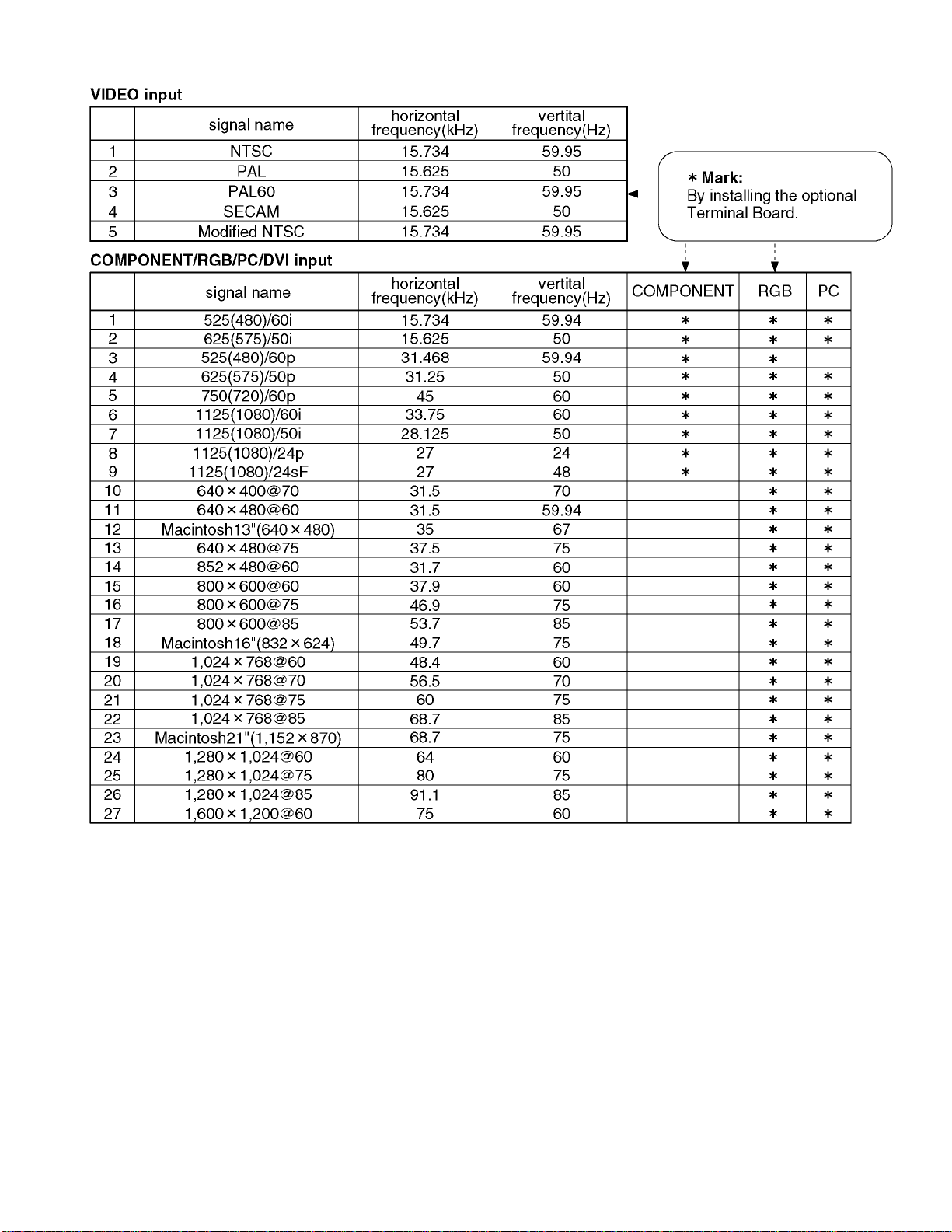
1 Applicable signals
3
Page 4
2 Safety Precautions
2.1. General Guidelines
1.When servicing, observe the original lead dress. If a short circuit is found, replace all parts which have been overheated or
damaged by the short circuit.
2.After servicing, see to it that all the protective devices such as insulation barriers, insulation papers shields are properly
installed.
3.After servicing, make the following leakage current checks to prevent the customer from being exposed to shock hazards.
2.1.1. Leakage Current Cold Check
1.Unplug the AC cord and connect a jumper between the two
prongs on the plug.
2.Measure the resistance value, with an ohmmeter, between
the jumpered AC plug and each exposed metallic cabinet
part on the equipment such as screwheads, connectors,
control shafts, etc. When the exposed metallic part has a
return path to the chassis, the reading should be between
1M9 and 5.2M9.
When the exposed metal does not have a return path to
the chassis, the reading must be
.
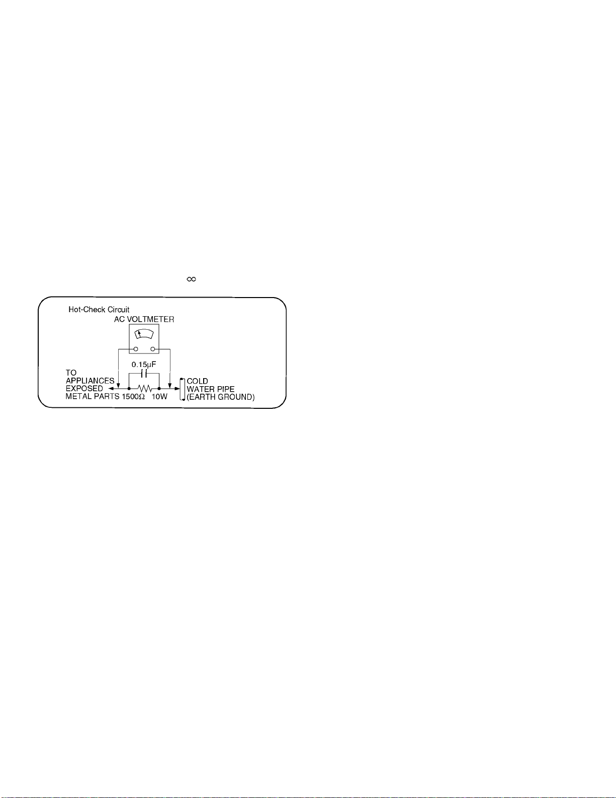
Figure 1
2.1.2. Leakage Current Hot Check (See
Figure 1.)
1.Plug the AC cord directly into the AC outlet. Do not use an
isolation transformer for this check.
2.Connect a 1.5k9 , 10 watts resistor, in parallel with a 0.15µF
capacitors, between each exposed metallic part on the set
and a good earth ground such as a water pipe, as shown in
Figure 1.
3.Use an AC voltmeter, with 1000 ohms/volt or more
sensitivity, to measure the potential across the resistor.
4.Check each exposed metallic part, and measure the
voltage at each point.
5.Reverse the AC plug in the AC outlet and repeat each of the
above measurements.
6.The potential at any point should not exceed 0.75 volts
RMS. A leakage current tester (Simpson Model 229 or
equivalent) may be used to make the hot checks, leakage
current must not exceed 1/2 milliamp. In case a
measurement is outside of the limits specified, there is a
possibility of a shock hazard, and the equipment should be
repaired and rechecked before it is returned to the
customer.
4
Page 5
3 Prevention of Electro Static Discharge (ESD) to
Electrostatically Sensitive (ES) Devices
Some semiconductor (solid state) devices can be damaged easily by static electricity. Such components commonly are called
Electrostatically Sensitive (ES) Devices. Examples of typical ES devices are integrated circuits and some field-effect transistors and
semiconductor "chip" components. The following techniques should be used to help reduce the incidence of component damage
caused by electro static discharge (ESD).
1.Immediately before handling any semiconductor component or semiconductor-equipped assembly, drain off any ESD on your
body by touching a known earth ground. Alternatively, obtain and wear a commercia lly available discharging ESD wrist strap,
which should be removed for potential shock reasons prior to applying power to the unit under test.
2.After removing an electrical assembly equipped with ES devices, place the assembly on a conductive surface such as alminum
foil, to prevent electrostatic charge buildup or exposure of the assembly.
3.Use only a grounded-tip soldering iron to solder or unsolder ES devices.
4.Use only an anti-static solder removal device. Some solder removal devices not classified as "anti-static (ESD protected)" can
generate electrical charge sufficient to damage ES devices.
5.Do not use freon-propelled chemicals. These can generate electrical charges sufficient to damage ES devices.
6.Do not remove a replacement ES device from its protective package until immediately before you are ready to install it. (Most
replacement ES devices are packaged with leads electrically shorted together by conductive foam, alminum foil or comparable
conductive material).
7.Immediately before removing the protective material from the leads of a replacement ES device, touch the protective material
to the chassis or circuit assembly into which the device will be installed.
Caution
Be sure no power is applied to the chassis or circuit, and observe all other safety precautions.
8.Minimize bodily motions when handling unpackaged replacement ES devices. (Otherwise hamless motion such as the brushing
together of your clothes fabric or the lifting of your foot from a carpeted floor can generate static electricity (ESD) sufficient to
damage an ES device).
5
Page 6
4 About lead free solder (PbF)
Note: Lead is listed as (Pb) in the periodic table of elements.
In the information below, Pb will refer to Lead solder, and PbF will refer to Lead Free Solder.
The Lead Free Solder used in our manufacturing process and discussed below is (Sn+Ag+Cu).
That is Tin (Sn), Silver (Ag) and (Cu) although other types are available.
This model uses Pb Free solder in it’s manufacture due to environmental conservation issues. For service and repair work, we’d
suggest the use of Pb free solder as well, although Pb solder may be used.
PCBs manufactured using lead free solder will have the PbF within a leaf Symbol
Caution
·Pb free solder has a higher melting point than standard solder. Typically the melting point is 50 ~ 70 °F (30~40 °C) higher.
Please use a high temperature soldering iron and set it to 700 ± 20 °F (370 ± 10 °C).
·Pb free solder will tend to splash when heated too high (about 1100 °F or 600 °C).
If you must use Pb solder, please completely remove all of the Pb free solder on the pins or solder area before applying Pb
solder. If this is not practical, be sure to heat the Pb free solder until it melts, before applying Pb solder.
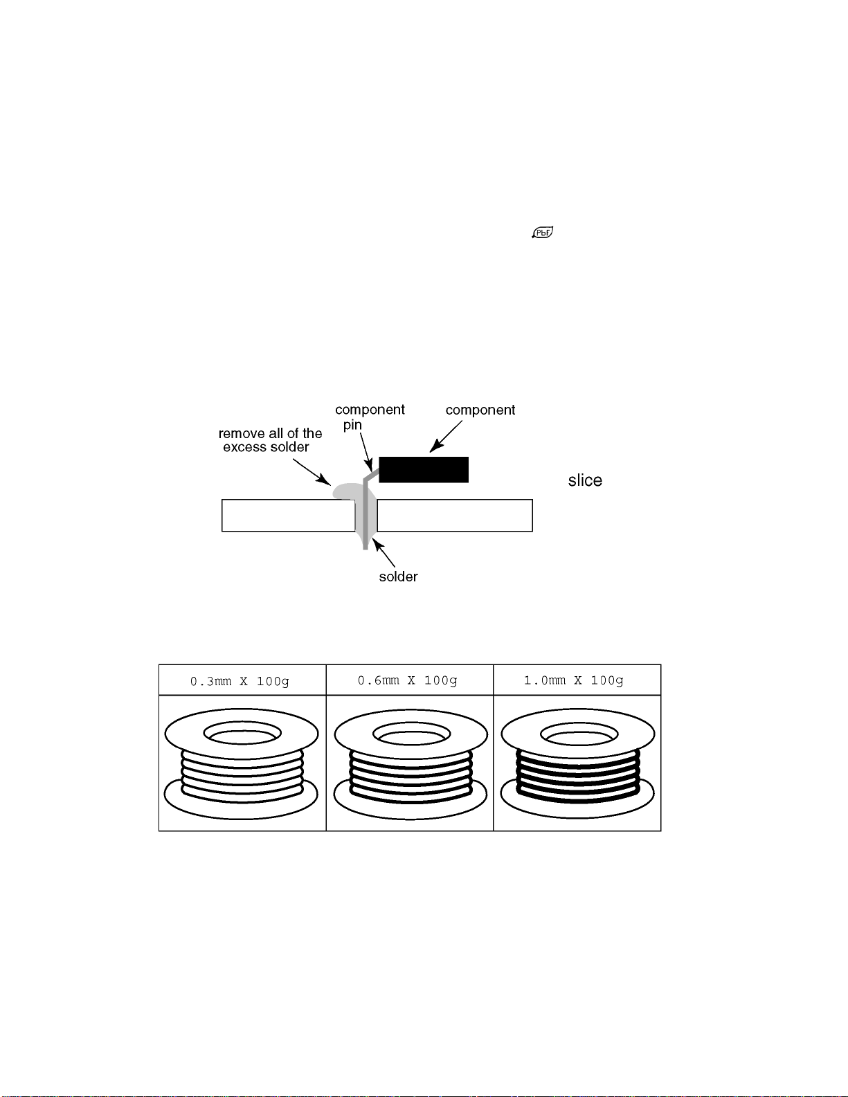
·After applying PbF solder to double layered boards, please check the component side for excess solder which may flow onto
the opposite side. (see figure below)
Suggested Pb free solder
There are several kinds of Pb free solder available for purchase. This product uses Sn+Ag+Cu (tin, silver, copper) solder.
However, Sn+Cu (tin, copper), Sn+Zn+Bi (tin, zinc, bismuth) solder can also be used.
stamped on the back of PCB.
6
Page 7

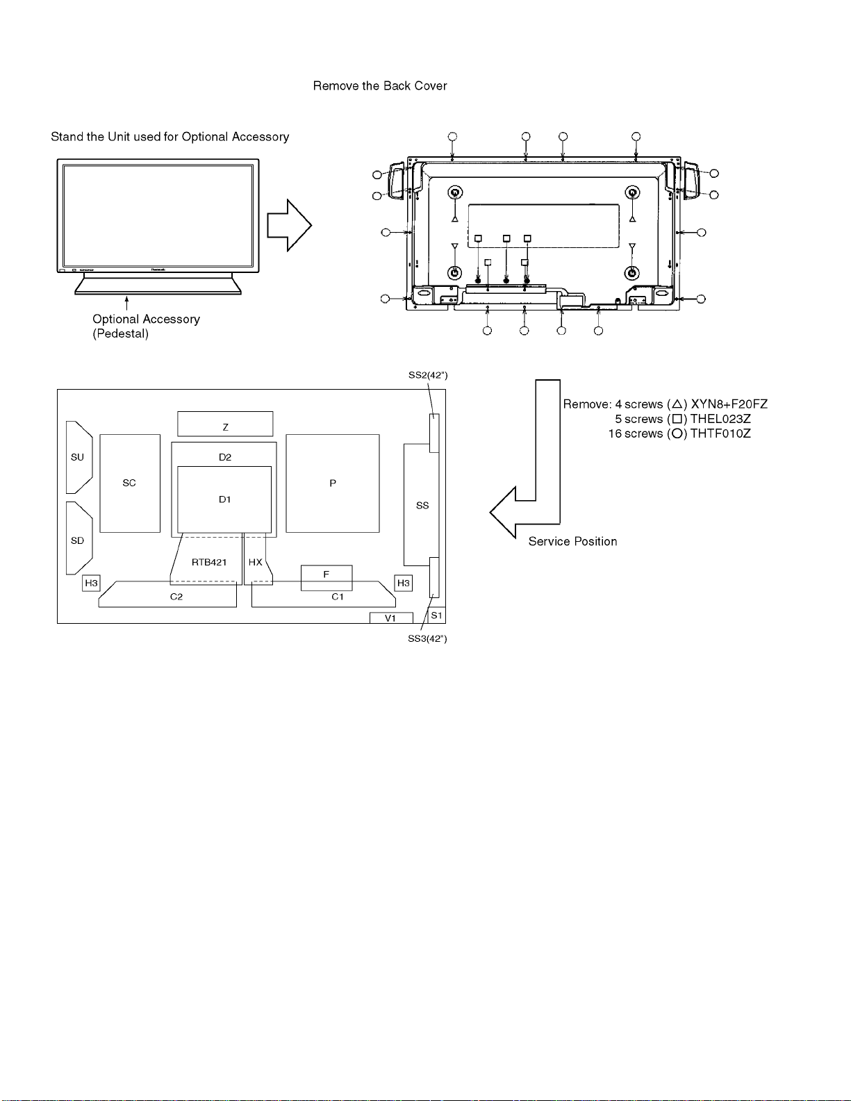
5 PCB Structure sheet of GP5D chassis
Board Name Function Remarks
D1 Format Converter 1
D2 Plasma AI Sub-Field Processor 1
Z Audio out
SS Sustain Out 1
SC Scan out 1
SU Sustain connection (Upper) 1
SD Sustain connection (Lower) 1
C1 Data Drive (Lower Right)
C2 Data Drive (Lower Left)
H3 Speaker terminal
S1 Power switch
SS2 Sustain connection (Upper)
SS3 Sustain connection (Lower)
V1 Front SW. & Remote receiver
F Line filter
P Power supply 1
HX PC_type_Input terminal
RTB421 RCA type_Input terminal
Remarks
1.Recommend PCB´s for initial service for GP5D chassis.
7
Page 8
6 Service Hint
∗ D1 board is not used for 42WP27C.
8
Page 9
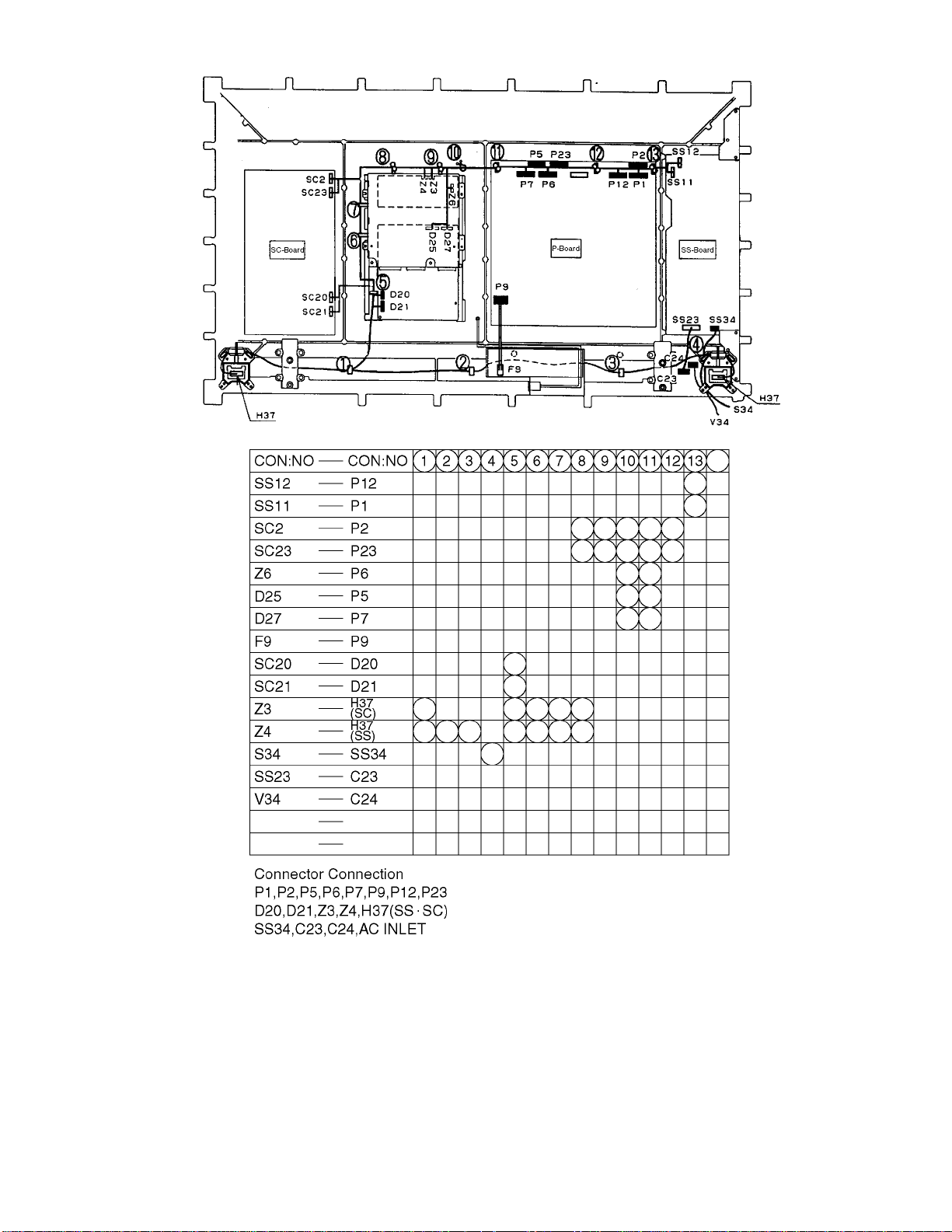
7 Location of Lead Wiring
9
Page 10
8 Adjustment Procedure
8.1. +B Set-up
8.1.1. Item / Preparation
1.Input a Grey scale signal.
2.Set the picture controls: Picture mode: Normal
White balance: Normal
8.1.2. Adjustments
Adjust and confirm indicated test point for the specified voltage.
Adjust
Name Volume Voltage Test Point
Vsus R540 170V ± 1V P1 pin 3
Vda R537 67V ± 0.5V P12 pin 1
Confirm
Name Voltage Test Point
15V 15.3V ± 0.5V P23 pin 2
13V 13.3V ± 0.5V P25 pin 5
15V 15.2V ± 0.5V P25 pin 1
Audio 13V 12.5V ± 0.8V P6 pin 1
Audio-13V -12.5V ± 0.8V P6 pin 3
5V 5.2V ± 0.3V P25 pin 7
STB 5V 5.0V ± 0.3V P27 pin 4
Fan 15V 15.0V ± 0.5V P10 pin 1
Fan 5V 5.2V ± 0.3V P10 pin 4
PFC 380V ± 15V C447(+)
8.2. Driver Set-up
8.2.1. Item / Preparation
1.Input an APL 100 % white signal.
2.Set the picture controls: Picture mode: Normal
White balance: Cool
Aspect: 16:9
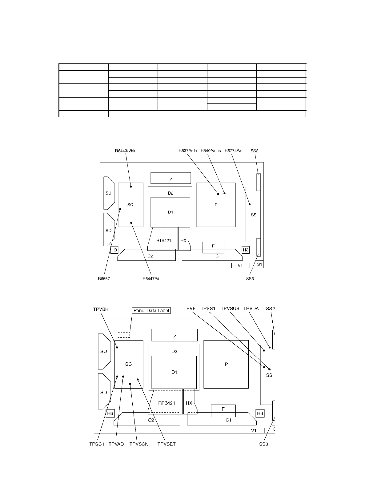
8.2.2. Adjustments
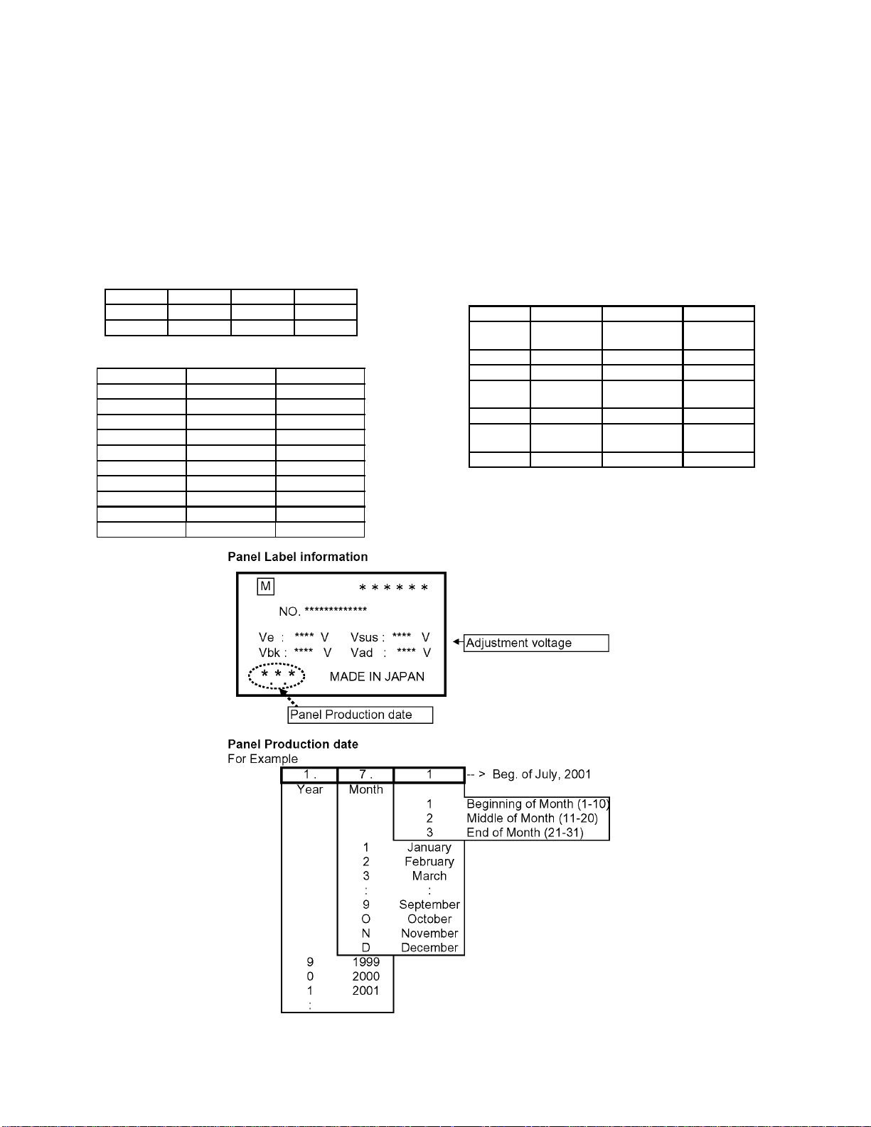
Adjust driver section voltages referring the panel data on the
panel data label.
Name Test Point Voltage Volume
Vsus TPVSUS
(SS)
Vbk TPVBK (SC) 155V ± 5V R6443 (SC)
Ve TPVE (SS) 150V ± 1V R6774 (SS)
Vset TPVSET
(SC)
Vad TPVAD (SC) -90V ± 1V R6477 (SC)
Vscn TPVSCN
(SC)
Vda TPVDA (SS) 67V ± 1V R537 (P)
*See the Panel label.
170V ± 1V R540 (P)
218V ± 6V ---
Vad*+118V ±2V---
10
Page 11
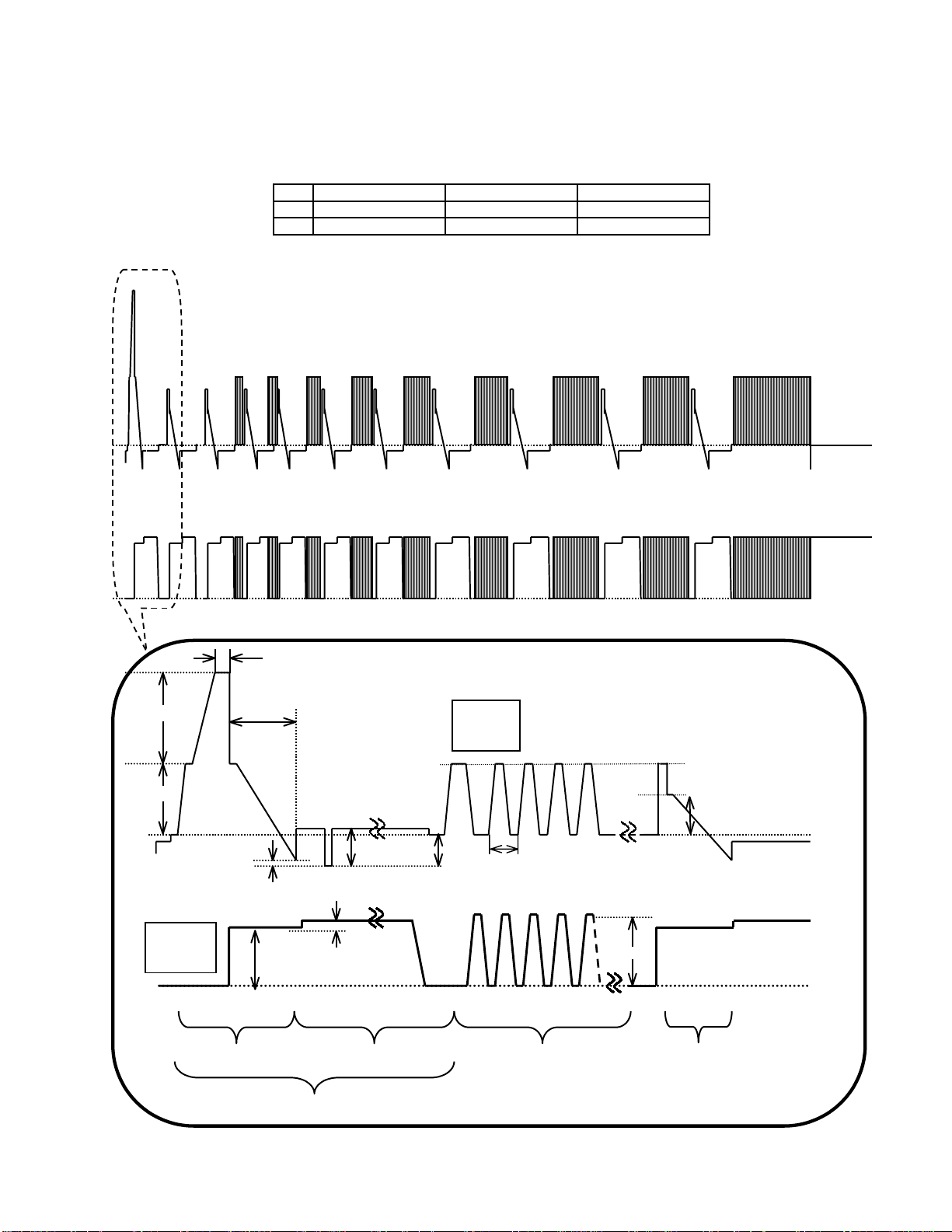
8.3. Initialization Pulse Adjust
1.Input a Cross hatch signal.
2.Set the picture controls: Picture mode: Normal
White balance: Cool
Adjust the indicated test point for the specified wave form.
Test point Volume Level
T1 TPSC1 (SC) --- 20 ± 15µ Sec
T2 TPSS1 (SS) R6557 (SC) 170 ± 20µ Sec
TPSC1 SCAN OUTPUT
TPSS1 SUSTAIN OUTPUT
T1
VSET
T2 170±20µs
Scan
TPSC1
VSUS VBK
VSCN VAD
VSET2 7±3V
5.0±0.6µs
Sustain
TPSS1
VE
VE2
VSUS
VSUS
INITIALIZE SCAN PRE-INITIALIZE
ADDRESS PERIOD
SUSTAIN
11
Page 12
8.4. P.C.B. (Printed Circuit Board) exchange
8.4.1. Caution
1. To remove P.C.B. , wait 1 minute after power was off for discharge from electrolysis capacitors.
8.4.2. Quick adjustment after P.C.B. exchange
P.C.B. Name Test Point Voltage Volume
P Board Vsus TPVSUS (SS) 170V ± 1V R540 (P)
Vda TPVDA (SS) 67V ± 1V R537 (P)
SC Board Vbk TPVBK (SC) 155V ± 5V R6443 (SC)
Vad TPVAD (SC) -90V ± 1V R6477 (SC)
SS Board Ve TPVE (SS) 150V ± 1V R6774 (SS)
153V ± 1V
D1 Board White blance, Pedestal and Sub brightness for NTSC, PAL, HD, PC and 625i signals
*See the Panel label.
8.5. Adjustment Volume Location
8.6. Test Point Location
∗ D1 board is not used for 42WP27C.
12
Page 13
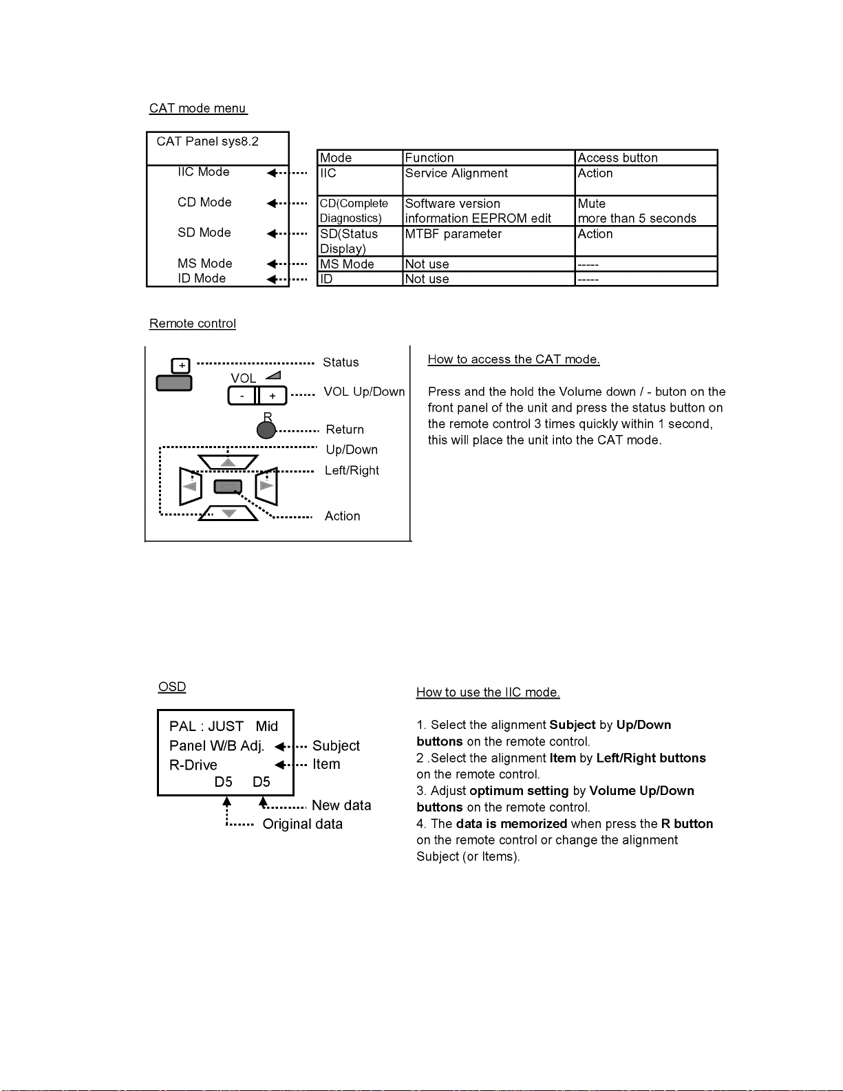
9 Service mode
9.1. CAT (computer Aided Test) mode
To exit the CAT mode, access the ID mode and switch off the main power.
9.1.1. IIC mode
Select the IIC mode by Up/Dow n button on the remote control at the front page of CAT mode then press the Action button on
the remote control.
Subject and item are mentioned on page 14.
To exit the IIC mode, press the R button on the remote control.
13
Page 14
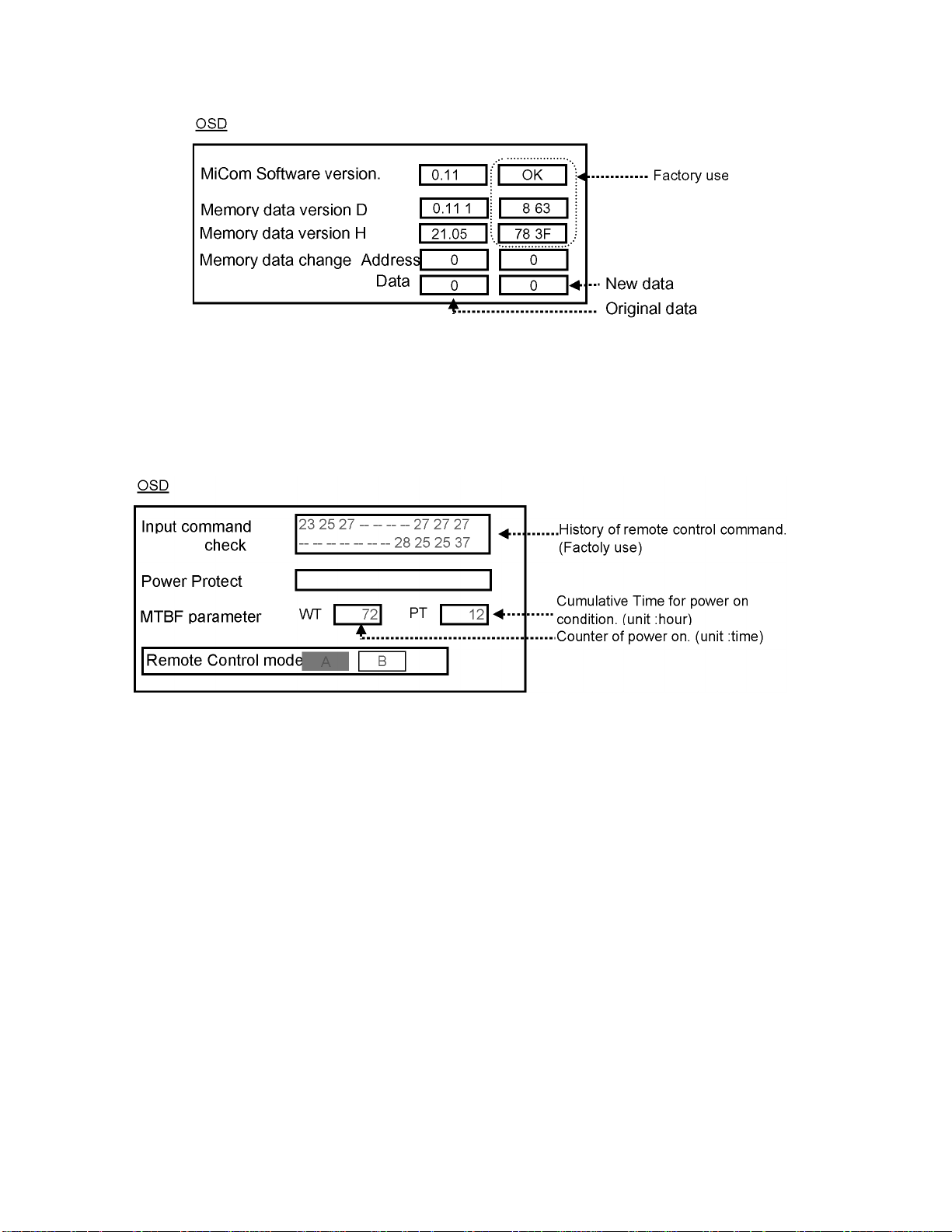
9.1.2. CD mode
Select the CD mode by Up/Down button on the remote control at the front page of CAT mode then press the Mute button on the
remote control more than 5 sec.
Micom software version (IC9354), this version can be upgrade by replace of new version IC.
To exit the CD mode, press the R button on the remote control.
9.1.3. SD mode
Select the SD mode by Up/Down button on the remote control at the front page of CAT mode then press the Action button on the
remote control.
To exit the SD mode, press the R button on the remote control.
14
Page 15
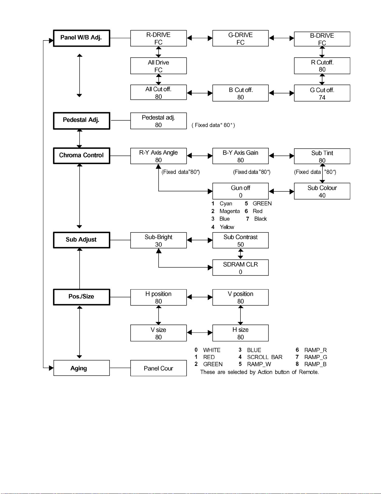
9.2. IIC mode structure (following items value is sample data.)
15
Page 16
10 Alignment
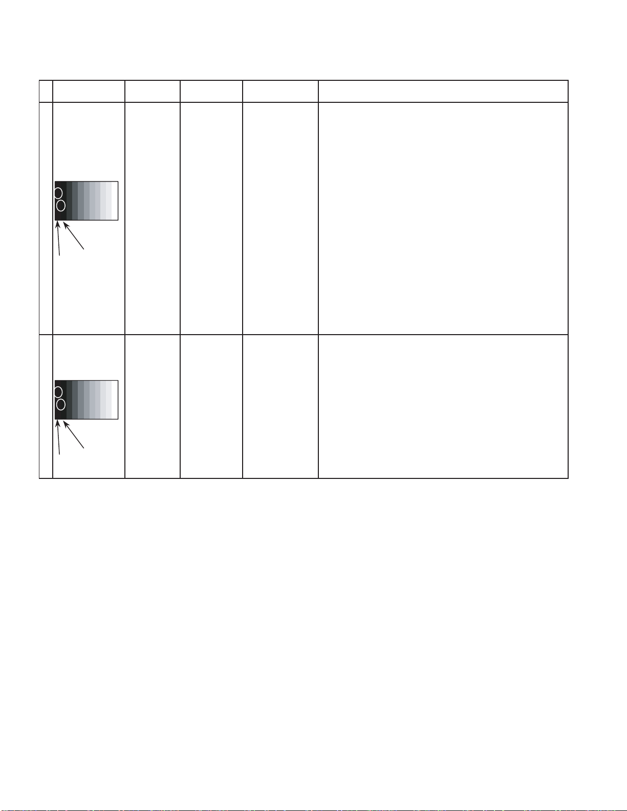
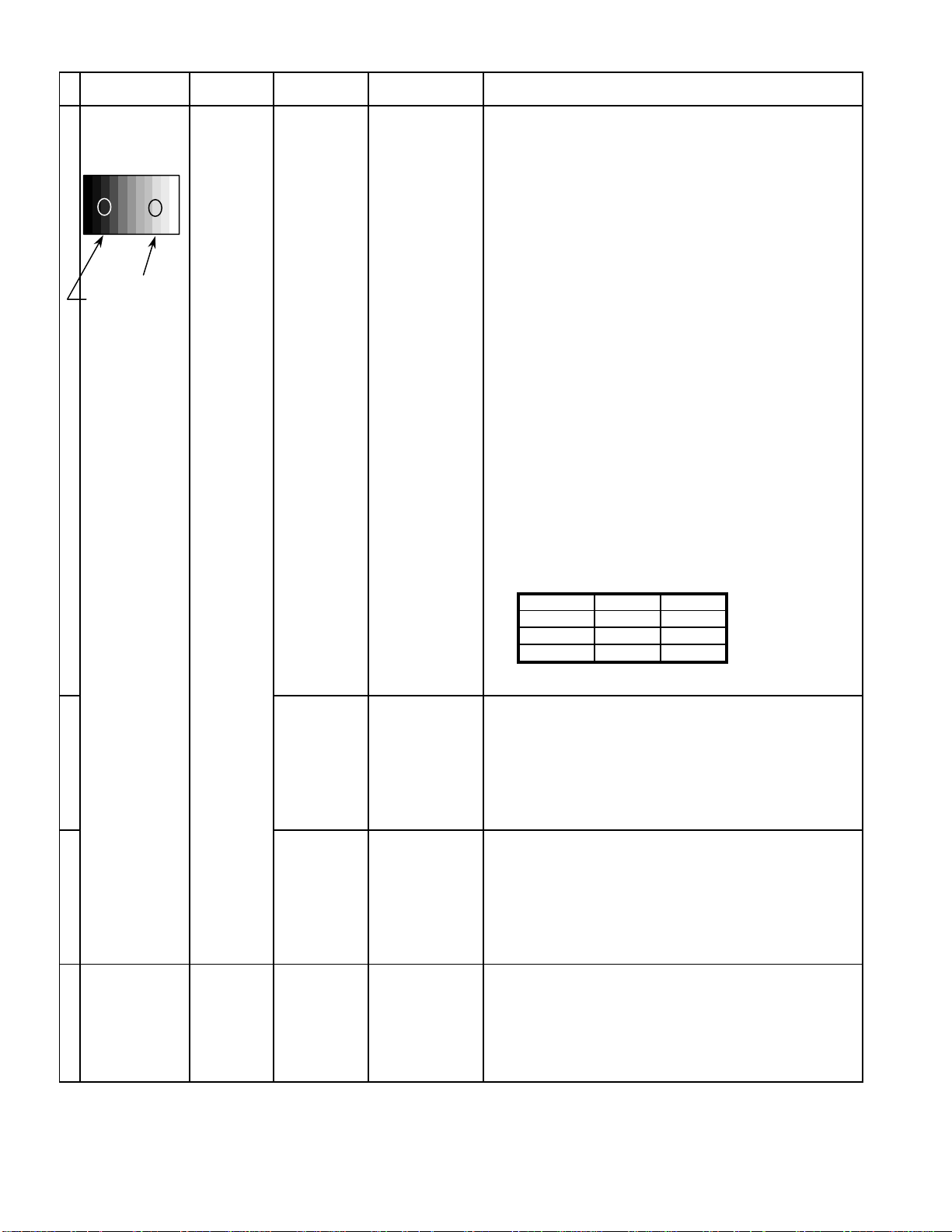
10.1. Pedestal setting
INPUT Alignment menu ProcedureEquipment Setting
** Adjust at the dark room.
1 Component Picture: PANEL W/B
(525i, 525p, 625i, Normal R cut off 1) Set R,G and B cut off to "
720i or 1080i) White balance: G cut off
Cool B cut off
Gray Scale Aspect:
Pattern 16:9
Black 2 %
Black 0 % at black 2% area and no emission at black 0% area.
Chroma Control:
Gun off
RGB Sub Adjust:
G Sub Bright
Chroma Control:
Gun off
RGB Sub Adjust:
B Sub Bright
Chroma Control:
Gun off
RGB Sub Adjust:
R Sub Bright
2) Set Gun off to "
3) Adjust G Sub bright to start some of green pixels emission
at black 2% area and no emission at black 0% area.
4) Set Gun off to "
5) Adjust B Sub bright to start some of blue pixels emission
6) Set Gun off to "
7) Adjust R Sub bright to start some of red pixels emission
at black 2% area and no emission at black 0% area.
5". (Only green pixels can emit.)
3". (Only blue pixels can emit.)
6". (Only red pixels can emit.)
80 ".
2 RGB(PC) Picture: 1) Change input to RGB signal.
Gray Scale Normal PANEL W/B
Pattern White balance: R,G,B cut off 2) Repeat procedure 1) to 7) of Component input signal.
Cool PANEL W/B
Aspect: R,G,B Drive
16:9
Black 2 %
Black 0 %
16
Page 17
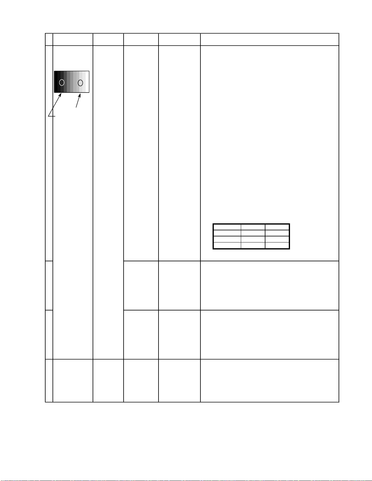
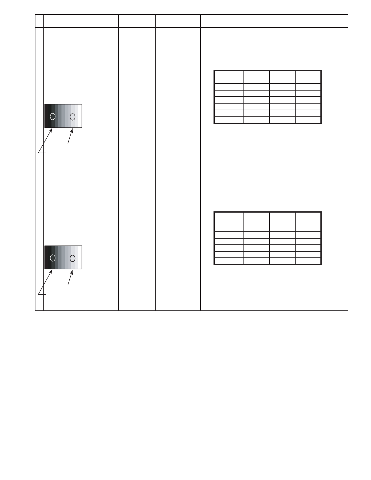
10.2. NTSC panel white balance
INPUT Alignment menu ProcedureEquipment Setting
1 NTSC Color Picture: 1) Find the nearest area to brightness of 10 cd/m2 as Low
Gray Scale Analyzer Normal Sub Adjust light by color sensor.
Pattern White balance: Sub Bright 2) Adjust Sub bright to set Low light level to 10 cd/m
Cool
Aspect: PANEL W/B
16:9 G cut off 3) Set G cut off to " 80 ".
PANEL W/B
B cut off 4) Adjust B and R cut off to set color temperature as
R cut off shown Fig.-01.
High light 75% Sub Adjust
Low light 15% Sub Bright 5) If Sub Bright is changed re-adjust it to set Low light
PANEL W/B
PANEL W/B
PANEL W/B
R,G,B Drive 10) Increase same steps of R, G and B Drive to set
R,G,B Drive largest level of 3 color drive to "FC".
PANEL W/B
R,G,B cut off 11) Re-adjust Low light level again.
exactly.
2
to 10 cd/m
6)Find 75% of white area by color sensor.
G Drive 7) Set G Drive to " E8 ".
B Drive 8) Adjust B and R Drive to set color temperature
R Drive as shown Fig.-01.
9) Repeat item 4) to 7) to set both Low light and
high light.
.
2
Color Temp. x y
Cool(Hi) 0.272 0.290
Normal(Mid) 0.288 0.296
Warm(Low) 0.313 0.329
Fig. -01
2 Picture: 1) Change white balance to "Normal".
Normal PANEL W/B
White balance: R,G,B cut off 2) Repeat procedure 3) to 11) of Cool mode.
Normal
PANEL W/B
Aspect: R,G,B Drive
16:9
3 Picture: 1) Change white balance to "Warm".
Normal PANEL W/B
White balance: R,G,B cut off 2) Repeat procedure 3) to 11) of Cool mode.
Warm
PANEL W/B
Aspect: R,G,B Drive
16:9
4 Picture: Picture Menu 1) Change color templature to "Cool".
Normal Sub Adjust
White balance: Sub Bright 2)Re-set Sub bright to "30"
Cool
Aspect:
16:9
17
Page 18

10.3. PAL/SECAM panel white balance
INPUT Alignment menu ProcedureEquipment Setting
1 PAL Color Picture: 1) Find the nearest area to brightness of 10 cd/m2 as Low
Gray Scale Analyzer Normal Sub Adjust light by color sensor.
Pattern White balance: Sub Bright 2) Adjust Sub bright to set Low light level to 10 cd/m
Cool exactly.
Aspect: PANEL W/B
16:9 G cut off 3) Set G cut off to " 80 ".
PANEL W/B
B cut off 4) Adjust B and R cut off to set color temperature as
R cut off shown Fig.-02.
High light 75% Sub Adjust
Low light 15% Sub Bright 5) If Sub Bright is changed re-adjust it to set Low light
to 10 cd/m
6)Find 75% of white area by color sensor.
PANEL W/B
G Drive 7) Set G Drive to " E8 ".
PANEL W/B
B Drive 8) Adjust B and R Drive to set color temperature
R Drive as shown Fig.-02.
9) Repeat procedure 4) to 7) to set both Low light and
high light.
PANEL W/B
R,G,B Drive 10) Increase same steps of R, G and B Drive to set
R,G,B Drive largest level of 3 color drive to "FC".
PANEL W/B
R,G,B cut off 11) Re-adjust Low light level again.
2.
2
Color Temp. x y
Cool(Hi) 0.272 0.290
Normal(Mid) 0.288 0.296
Warm(Low) 0.313 0.329
Fig. -02
2 Picture: 1) Change white balance to "Normal".
Normal PANEL W/B
White balance: R,G,B cut off 2) Repeat procedure 3) to 11) of Cool mode.
Normal PANEL W/B
Aspect: R,G,B Drive
16:9
3 Picture: 1) Change white balance to "Warm".
Normal PANEL W/B
White balance: R,G,B cut off 2) Repeat procedure 3) to 11) of Cool mode.
Warm PANEL W/B
Aspect: R,G,B Drive
16:9
4 Picture: Picture Menu 1) Change color templature to "Cool".
Normal Sub Adjust
White balance: Sub Bright 2)Re-set Sub bright to "30"
Cool
Aspect:
16:9
18
Page 19
Alignment menu ProcedureEquipment Setting
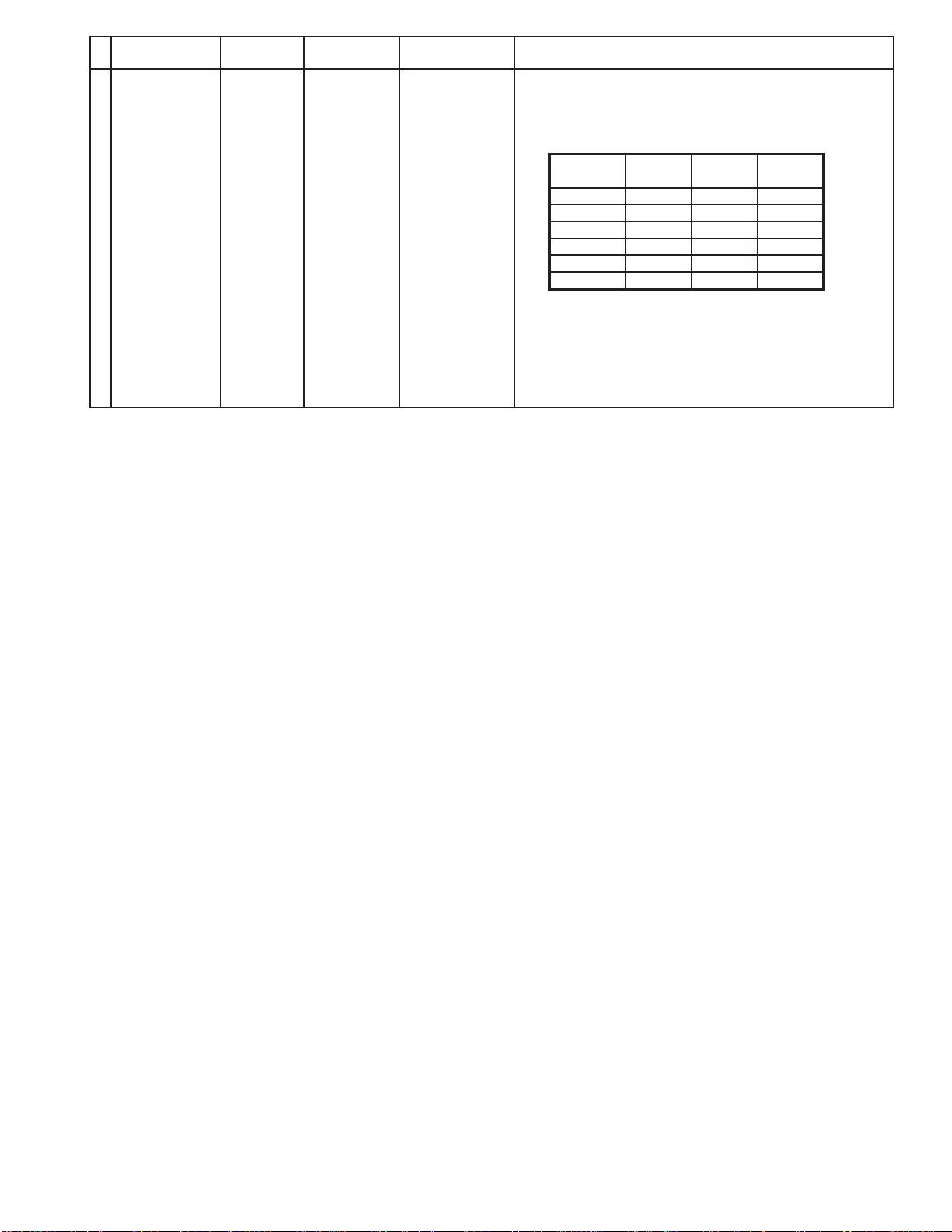
5 Picture: 1) Write down each color temaparature of R,G,B drive and
Normal Cut off data as follows.
Aspect:
16:9
White
White balance:
Cool
Normal
Warm
SECAM signal 2) Input SECAM signal.
Balance Cool Normal Warm
R Drive
G Drive
B Drive
R Cut off
G Cut off
B Cut off
3) Copy PAL R,G,B drive and cut off data of each white
balance mode to SECAM position.
19
Page 20
10.4. PC/RGB panel white balance
INPUT Alignment menu ProcedureEquipment Setting
1 PC Color Picture: 1) Find the nearest area to brightness of 10 cd/m2 as Low
Gray Scale Analyzer Normal Sub Adjust light by color sensor.
Pattern White balance: Sub Bright 2) Adjust Sub bright to set Low light level to 10 cd/m
Cool exactly.
Aspect: PANEL W/B
16:9 G cut off 3) Set G cut off to " 80 ".
PANEL W/B
B cut off 4) Adjust B and R cut off to set color temperature as
R cut off shown Fig.-03.
High light 75% Sub Adjust
Low light 15% Sub Bright 5) If Sub Bright is changed re-adjust it to set Low light
to 10 cd/m
6)Find 75% of white area by color sensor.
PANEL W/B
G Drive 7) Set G Drive to " E8 ".
PANEL W/B
B Drive 8) Adjust B and R Drive to set color temperature
R Drive as shown Fig.-03.
9) Repeat item 4) to 7) to set both Low light and
high light.
PANEL W/B
R,G,B Drive 10) Increase same steps of R, G and B Drive to set
R,G,B Drive largest level of 3 color drive to "FC".
PANEL W/B
R,G,B cut off 11) Re-adjust Low light level again.
2
.
2
Color Temp. x y
Cool(Hi) 0.272 0.290
Normal(Mid) 0.288 0.296
Warm(Low) 0.313 0.329
Fig. -03
2 Picture: 1) Change white balance to "Normal".
Normal PANEL W/B
White balance: R,G,B cut off 2) Repeat procedure 3) to 11) of Cool mode.
Normal PANEL W/B
Aspect: R,G,B Drive
16:9
3 Picture: 1) Change white balance to "Warm".
Normal PANEL W/B
White balance: R,G,B cut off 2) Repeat procedure 3) to 11) of Cool mode.
Warm PANEL W/B
Aspect: R,G,B Drive
16:9
4 Picture: Picture Menu 1) Change color templature to "Cool".
Normal Sub Adjust
White balance: Sub Bright 2)Re-set Sub bright to "30"
Cool
Aspect:
16:9
20
Page 21
INPUT Alignment menu ProcedureEquipment Setting
5 Picture: 1) Write down each color temaparature of R,G,B drive and
Normal Cut off data as follows.
Aspect:
16:9
White
RGB
Gray Scale
Pattern
White balance:
Cool R Drive
Normal G Drive
Warm B Drive
Balance Cool Normal Warm
R Cut off
G Cut off
B Cut off
2) Input RGB signal.
High light 75%
Low light 15% 3) Copy PC R,G,B drive and cut off data of each white
balance mode to RGB position.
6 Picture: 1) Write down each color temaparature of R,G,B drive and
Normal Cut off data as follows.
Aspect:
16:9
White
DVI
Gray Scale
Pattern
White balance:
Cool R Drive
Normal G Drive
Warm B Drive
Balance Cool Normal Warm
R Cut off
G Cut off
B Cut off
2) Input DVI signal.
High light 75%
Low light 15% 3) Copy PC R,G,B drive and cut off data of each white
balance mode to DVI position.
21
Page 22
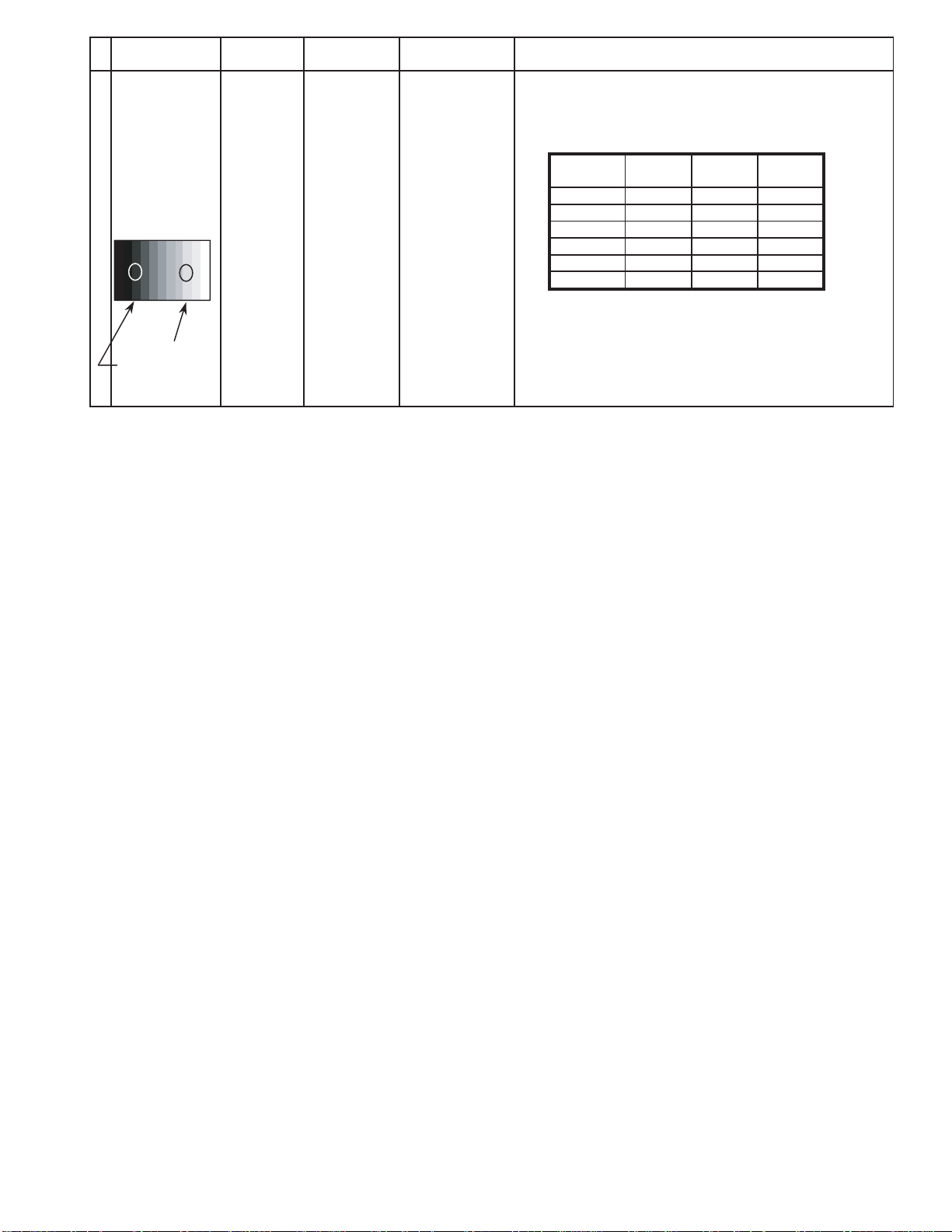
10.5. HD/ 525i /525p panel white balance
INPUT Alignment menu ProcedureEquipment Setting
1HD(720i or 1080i) Color Picture: 1) Find the nearest area to brightness of 10 cd/m2 as Low
Gray Scale Analyzer Normal Sub Adjust light by color sensor.
Pattern White balance: Sub Bright 2) Adjust Sub bright to set Low light level to 10 cd/m
Cool
Aspect: PANEL W/B
16:9 G cut off 3) Set G cut off to " 80 ".
PANEL W/B
B cut off 4) Adjust B and R cut off to set color temperature as
R cut off shown Fig.-04.
High light 75% Sub Adjust
Low light 15% Sub Bright 5) If Sub Bright is changed re-adjust it to set Low light
PANEL W/B
G Drive 7) Set G Drive to " E8 ".
PANEL W/B
R Drive as shown Fig.-04.
PANEL W/B
R,G,B Drive 10) Increase same steps of R, G and B Drive to set
R,G,B Drive largest level of 3 color drive to "FC".
PANEL W/B
R,G,B cut off 11) Re-adjust Low light level again.
exactly.
2
to 10 cd/m
6)Find 75% of white area by color sensor.
B Drive 8) Adjust B and R Drive to set color temperature
9) Repeat item 4) to 7) to set both Low light and
high light.
.
2
Color Temp. x y
Cool(Hi) 0.272 0.290
Normal(Mid) 0.288 0.296
Warm(Low) 0.313 0.329
Fig. -04
2 Picture: 1) Change white balance to "Normal".
Normal PANEL W/B
White balance: R,G,B cut off 2) Repeat procedure 3) to 11) of Cool mode.
Normal
PANEL W/B
Aspect: R,G,B Drive
16:9
3 Picture: 1) Change white balance to "Warm".
Normal PANEL W/B
White balance: R,G,B cut off 2) Repeat procedure 3) to 11) of Cool mode.
Warm
PANEL W/B
Aspect: R,G,B Drive
16:9
4 Picture: Picture Menu 1) Change color templature to "Cool".
Normal Sub Adjust
White balance: Sub Bright 2)Re-set Sub bright to "30"
Cool
Aspect:
16:9
22
Page 23
INPUT Alignment menu ProcedureEquipment Setting
5 Picture: 1) Write down each color temaparature of R,G,B drive and
Normal Cut off data as follows.
Aspect:
16:9
White
White balance:
RGB
Gray Scale
Pattern
High light 75%
Low light 15% 3) Copy HD drive and cut off data of each white
Cool
Normal
Warm
Balance Cool Normal Warm
R Drive
G Drive
B Drive
R Cut off
G Cut off
B Cut off
2)Change input signal to 525i and 525p.
balance mode to each signals position.
23
Page 24

10.6. 625i panel balance
INPUT Alignment menu ProcedureEquipment Setting
1 625i Color Picture: 1) Find the nearest area to brightness of 10 cd/m2 as Low
Gray Scale Analyzer Normal Sub Adjust light by color sensor.
Pattern White balance: Sub Bright 2) Adjust Sub bright to set Low light level to 10 cd/m
Cool exactly.
Aspect: PANEL W/B
16:9 G cut off 3) Set G cut off to " 80 ".
PANEL W/B
B cut off 4) Adjust B and R cut off to set color temperature as
R cut off shown Fig.-05.
High light 75% Sub Adjust
Low light 15% Sub Bright 5) If Sub Bright is changed re-adjust it to set Low light
to 10 cd/m
6)Find 75% of white area by color sensor.
PANEL W/B
G Drive 7) Set G Drive to " E8 ".
PANEL W/B
B Drive 8) Adjust B and R Drive to set color temperature
R Drive as shown Fig.-05.
9) Repeat item 4) to 7) to set both Low light and
high light.
PANEL W/B
R,G,B Drive 10) Increase same steps of R, G and B Drive to set
R,G,B Drive largest level of 3 color drive to "FC".
PANEL W/B
R,G,B cut off 11) Re-adjust Low light level again.
2
.
2
Color Temp. x y
Cool(Hi) 0.272 0.290
Normal(Mid) 0.288 0.296
Warm(Low) 0.313 0.329
Fig. -05
2 Picture: 1) Change white balance to "Normal".
Normal PANEL W/B
White balance: R,G,B cut off 2) Repeat procedure 3) to 11) of Cool mode.
Normal PANEL W/B
Aspect: R,G,B Drive
16:9
3 Picture: 1) Change white balance to "Warm".
Normal PANEL W/B
White balance: R,G,B cut off 2) Repeat procedure 3) to 11) of Cool mode.
Warm PANEL W/B
Aspect: R,G,B Drive
16:9
4 Picture: Picture Menu 1) Change color templature to "Cool".
Normal Sub Adjust
White balance: Sub Bright 2)Re-set Sub bright to "30"
Cool
Aspect:
16:9
24
Page 25
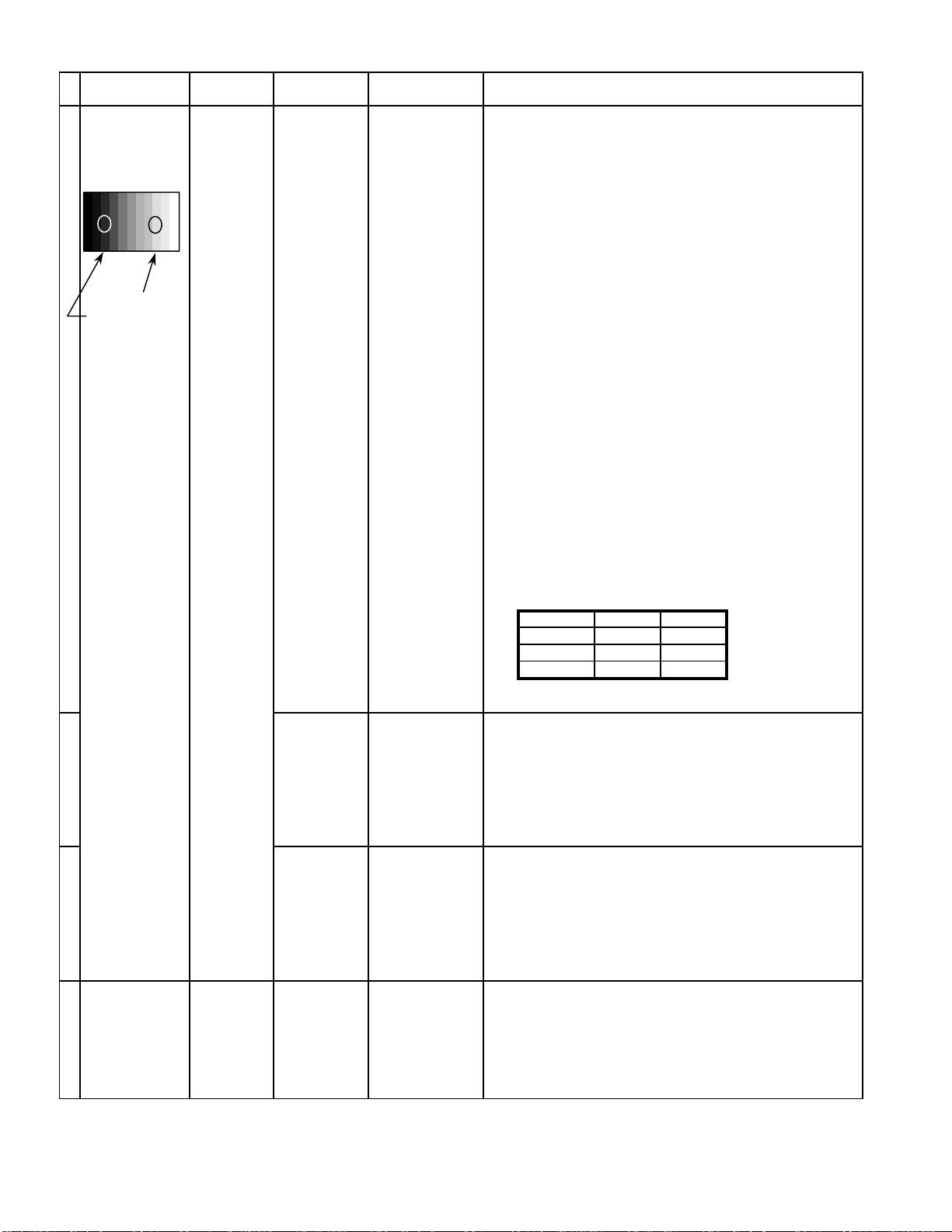
10.7. Sub brightness setting
INPUT Alignment menu ProcedureEquipment Setting
** Adjust at the dark room.
1 NTSC Picture: PANEL W/B
Gray Scale Normal All cut off 1) Set white balance to
Pattern Aspect:
16:9 2) Adjust All cut off to start some pixels emission
at black 2% area and no emission at black 0% area.
3) Write down all cut off data.
Cool
.
4) Set white balance to
Black 2 %
Black 0 % 5) Adjust All cut off to set same data of Cool mode.
6) Set white balance to
7) Adjust All cut off to set same data of Cool mode.
** Adjust at the dark room.
2 PAL Picture: PANEL W/B
Gray Scale Normal All cut off 1) Set white balance to
Pattern Aspect:
16:9 2) Adjust All cut off to start some pixels emission
at black 2% area and no emission at black 0% area.
3) Write down all cut off data.
4) Set white balance to
Black 2 %
Black 0 % 5) Adjust All cut off to set same data of Cool mode.
6) Set white balance to
7) Adjust All cut off to set same data of Cool mode.
SECAM 8) Change to SECAM signal.
Gray Scale
Pattern 9) Copy PAL All cut off data to SECAM mode.
Nornal
warm
Cool
Nornal
warm
.
.
.
.
.
** Adjust at the dark room.
3 PC Picture: PANEL W/B
Gray Scale Normal All cut off 1) Set white balance to
Pattern Aspect:
16:9 2) Adjust All cut off to start some pixels emission
at black 2% area and no emission at black 0% area.
3) Write down all cut off data.
4) Set white balance to
Black 2 %
Black 0 % 5) Adjust All cut off to set same data of Cool mode.
6) Set white balance to
7) Adjust All cut off to set same data of Cool mode.
RGB
Gray Scale
Pattern
DVI
Gray Scale
Pattern
8) Change to RGB input signal.
9) Copy PC All cut off data to RGB mode.
10) Change to DVI input signal.
11) Copy PC All cut off data to DVI mode.
Cool
Nornal
warm
.
.
.
25
Page 26
Alignment menu ProcedureINPUT Equipment Setting
** Adjust at the dark room.
4 525i Picture: PANEL W/B
Gray Scale Normal All cut off 1) Set white balance to
Pattern Aspect:
16:9 2) Adjust All cut off to start some pixels emission
at black 2% area and no emission at black 0% area.
3) Write down all cut off data.
Cool
.
4) Set white balance to
Nornal
.
Black 2 %
Black 0 % 5) Adjust All cut off to set same data of Cool mode.
6) Set white balance to
warm
.
7) Adjust All cut off to set same data of Cool mode.
525p 8) Change to 525p signal.
Gray Scale
Pattern 9) Copy 525i All cut off data to 525p mode.
HD
(720i or 1080i) 8) Change to HD signal.
Gray Scale
Pattern 9) Copy 525i All cut off data to HD mode.
** Adjust at the dark room.
5 625i Picture: PANEL W/B
Cool
Gray Scale Normal All cut off 1) Set white balance to
.
Pattern Aspect:
16:9 2) Adjust All cut off to start some pixels emission
at black 2% area and no emission at black 0% area.
3) Write down all cut off data.
4) Set white balance to
Nornal
.
Black 2 %
Black 0 % 5) Adjust All cut off to set same data of Cool mode.
6) Set white balance to
warm
.
7) Adjust All cut off to set same data of Cool mode.
26
Page 27
11 Trouble shooting guide
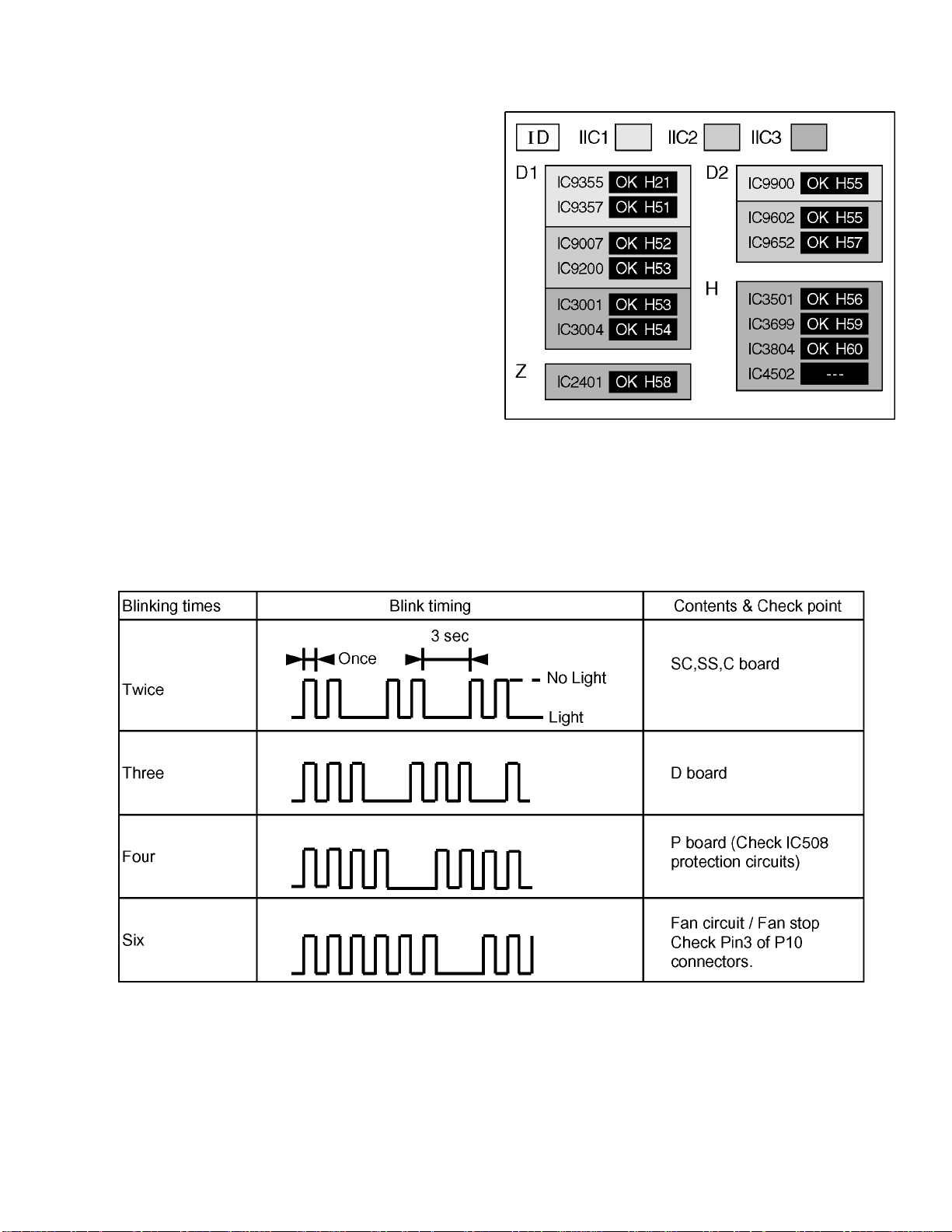
11.1. Self Check
11.1.1. Display Indication
1.Self-check is used to automatically check the bus line
controlled circuit of the Plasma display.
2.To get into the Self-check mode, press the volume down
button on the customer controls at the front of the set, at the
same time pressing the OFF-TIMER button on the remote
control, and the screen will show :-
If the CCU ports have been checked and found to be incorrect
Or not located then " - - " will appear in place of " OK "
Note:
In case of disconnected of RTB421 “IC3699 - -” is
displayed.
11.1.2. Power LED Blinking timing chart
1.Subject
Information of LED Flashing timing chart.
2.Contents
When an abnormality has occurred the unit, the protection circuit operates and reset to the stand by mode. At this time, the
defective block can be identified by the number of blinkes of the Power LED on the front panel of the unit.
3.Remarks
Above Fan function is operated during the fans are installed.
27
Page 28
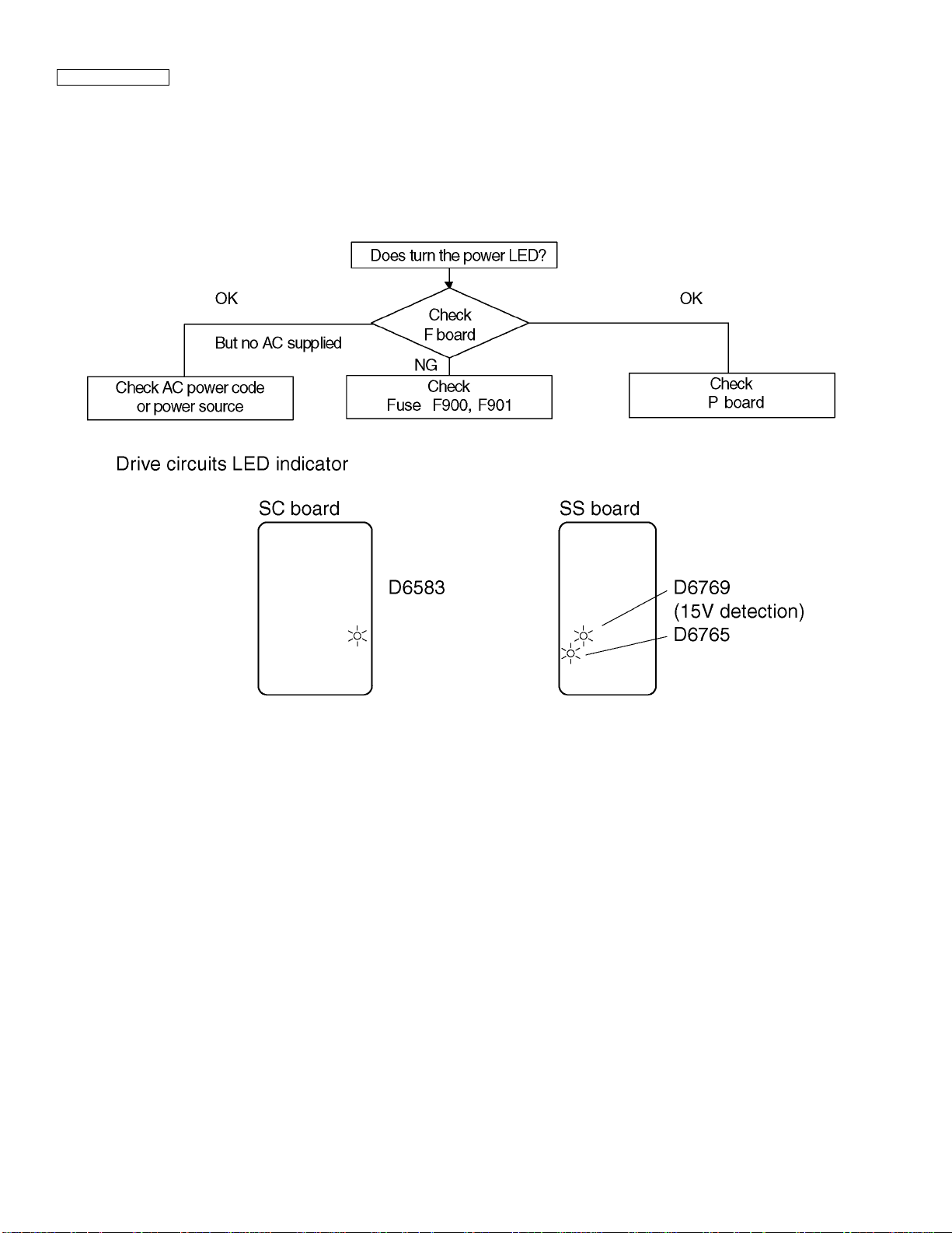
11.2. No Power
First check point
There are following 3 states of No Power indication by power LED.
1.No lit
2.Green is lit then turns red blinking a few seconds later.
3.Only red is lit.
1.No lit
28
Page 29
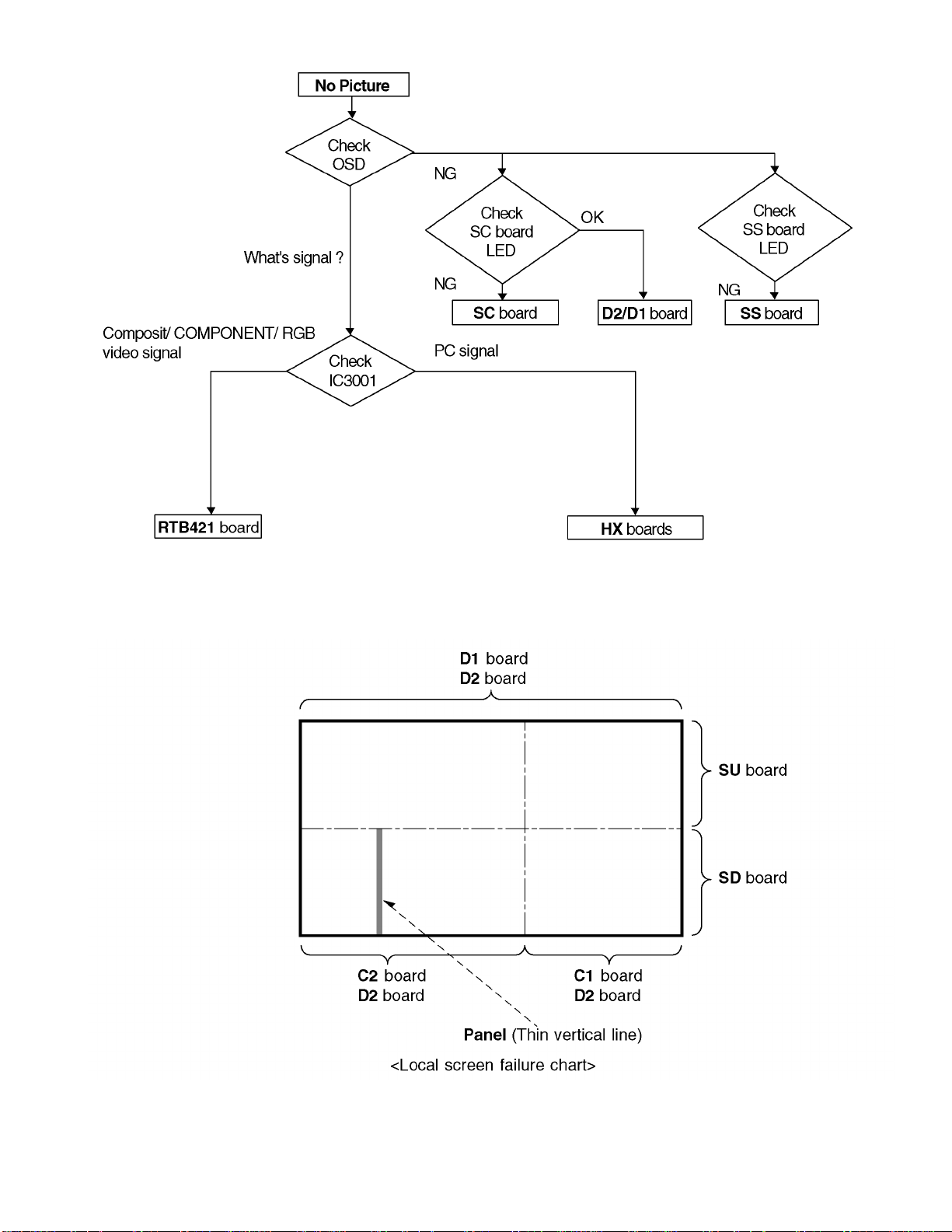
11.3. No Picture
11.4. Local screen failure
Plasma display may have local area failure on the screen. Fig - 1 is the possible defect P.C.B. for each local area.
Fig - 1
29
Page 30
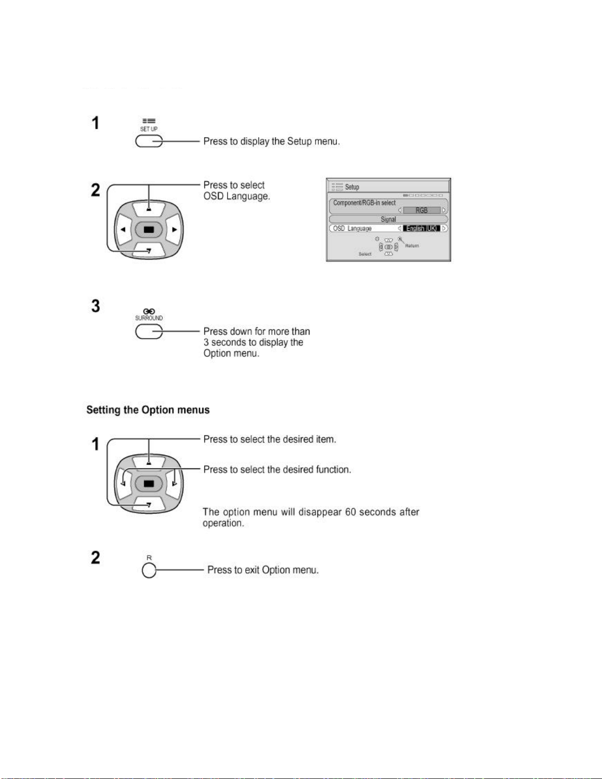
12 Option Setting
How to access the Option menu
30
Page 31

Hidden Option Menu for GP5D series
GP5D chassis series have special function and operation setting facility called Option Menu. This Option Menu is useful for
special function required customers. This should be set at the installation stage. The end user could not set or change these
because of hidden On screen menu.
Option menus default setting Contents
Wobbling Off Wobbling operation On/Off.
Off-timer function Enable Off-timer operation Enable/Disable.
On Screen display On Enable/Disable to display input mode indication after power on and no signal
Initial Input Off Sets the initial input mode when the power is turned on . Allow input mode
Initial VOL. level Off Sets the initial volume level when the power is turned on. Allow Volume control
Maximum VOL. Level Off Sets the maximum volume to desired level. Volume cannot exceed this level.
INPUT lock Off Fixes the input mode to AV, Component/RGB or PC. Can not change input
Button lock Off Enable/Disable front operation buttons (Input and/or volume up/down)
Studio W/B Off Set warm mode color temperature to 3,200 Kelvin.
Remocon User Level Off Remote key invalidation.
ID Select 0to100 Set ID number from 001 to 100.
Remote ID Off Remote ID function On/Off.
Serial Off Serial ID function On/Off
The outline of burnt image will be blurred by intermittent image sift.
indication.
selection while power is on.
while power is on.
mode by input selection key.
Off : Valid key is all key of remote.
User1 : Valid key are only Stand-by (ON/OFF), Input, Status, Surround, Sound
mute On/Off, and volume adjustment.
User2 : Valid key is only Stand-by (ON/OFF).
User3 : All keys are null and void
(While the Remote ID on, standard remote function can not control the unit.)
Note :
How to set Remocon User Level and Remote ID off
1.Access service mode (CAT-mode) and press SET UP key on remote.
2.Accsess Hidden option menu.
3.Change Remocon User Level and/ or Remote ID set to Off.
31
Page 32

This page is not printed.
32
Page 33

13 Conductor Views
13.1. F-Board
6
5
F
4
F-BOARD
TXN/F1MMSE
3
2
1
ABCDEFGH I
33
Page 34

13.2. P-Board
P-BOARD (FOIL SIDE)
TNPA2599
6
5
4
3
2
1
A
C E GIBDFH
34
Page 35

P
Parts Location
IC
IC410 D-4
IC411 E-5
IC430 D-3
IC465 B-5
IC501 B-2
IC502 C-3
IC503 B-3
IC504 C-4
IC505 C-4
IC506 E-5
IC507 D-5
IC508 B-5
P-BOARD (FOIL SIDE)
TRANSISTOR TP
Q401 F-5
Q402 F-5
Q403 F-5
Q410 F-5
Q431 D-2
Q432 D-3
Q433 D-3
Q434 D-3
Q435 B-2
Q436 B-2
Q437 B-2
Q438 B-3
Q439 A-3
Q501 A-2
Q502 C-5
Q503 B-5
Q504 B-5
Q505 B-5
Q506 F-5
TPP1 B-1
Parts Location
IC
IC410 B-4
IC411 A-5
IC430 B-3
IC465 E-5
IC501 E-2
IC502 D-3
IC503 D-3
IC504 D-4
IC505 D-4
IC506 B-5
IC507 C-5
IC508 E-5
P-BOARD (COMPONENT SIDE)
TRANSISTOR TP
Q401 A-5
Q402 A-5
Q403 A-5
Q410 A-6
Q431 C-2
Q432 C-3
Q433 C-2
Q434 C-3
Q435 E-2
Q436 E-2
Q437 E-2
Q438 E-3
Q439 E-3
Q501 E-2
Q502 D-5
Q503 D-5
Q504 D-5
Q505 E-5
Q506 A-5
TPP1 E-1
35
Page 36

P-BOARD (COMPONENT SIDE)
TNPA2599
6
5
4
3
2
1
A
C E GIBDFH
36
Page 37

13.3. HX-Board
6
HX-BOARD(FOIL SIDE)
TZTNP001PMSE
HX-BOARD(COMPONENT SIDE)
TZTNP001PMSE
5
4
HX
Parts Location
HX-BOARD
IC
3
IC3502 F-2
IC3515 E-2
TRANSISTOR
Q3507 F-3
Q3508 F-3
Q3509 F-3
Q3513 E-4
Q3514 E-4
Q3515 F-4
Q3516 F-4
Q3531 E-3
Q3532 F-3
2
1
ABCDEFGH I
37
Page 38

13.4. Option RTB421
6
RTB421-BOARD(FOIL SIDE)
TXNHZ10JJS
5
4
5
JS32
JS31
41
TP327
TP330
IC699
A2
A24
A25
B24
B25
TP328
TP329
R516
R519
R520
8
C506
TP331
R522
R521
R517
R518
C709
C705
C706
C896
C707
C702
C704
C862
C863
R841
C854
H1
Q816
R897
R866
R880
R882
C895
R883
C888
R843
R878
Q814
R888
C869
R887
C867
R847
R842
TP332
JS15
R872
C876
C889
R851
R881
JS14
JS16
R861
C891
R852
C899
R870
Q817
A20
A1
A19
B2
B20
B1
B19
JS13
TP333
C885
C877
R860
TP334
R853
C882
C884
C897
C874
R848
R864
R865
R874
R877
JS28
JS29
JS30
TP323
TP315
R537
R550
R534
JS19
R869
R846
C729
C878
C880
C881
TP316
R549
R509
R514
R508
R503
R879
R886
R875
R873
TP317
JS36
JS35
H2
TP322
TP314
R536
R533
R868
R535
R548
R507
R513
R506
R502
JS23
R876
R885
A2
A1
B2
B1
TP313
C507
R511
R505
R504
R532
JS21
R501
2
JS22
JS24
JS20
HZ
RTB421
3
CR NO.
R340
R337
Q306
R345
R348
TP318
2
R346
R330
R331
JK305
R
C307
TP305
R347
TP319
R327
R336
C306
R328
R329
R306
R342
C309
R344
R343
R341
R326
R321
R315
R314
R308
TP303
TP304
B
C843
JS8
R814
Q808
C807
R305
TP302
TP301
R809
R810
R896
R805
Q804
R804
R310
R319
R307
C302
R303
C301
R304
R309
R349
R350
JK301
C
R819
R807
C819
R821
R822
R817
R322
R384
R381 R382
C356
R359
R352
TP307
JK307
R
3
Q302
R324
R320
R312
R317
R313
R301
Y
GR
C824
C840
C841
R831
R830
C839
R829
Q810
R380
TP306
R832
R833
R823
R824
Q809
R825
R827
R383
C355
R358
R351
L
TP312
R828
C825
R826
JS9
C828
R834
C832
C822
TP321
R378
R366
R379
R361
R367
C352
R357
JK308
GAP11
R
R836
C826
C820
R816
R806
R393
R389
C351
TP311
GAP10
L
C842
JS10
R813
R812
L807
C805
R808
C801
R803
TP320
TP324
R394
R390
R360
R391
C359
R356
R355
TP310
JK306
GAP9
R
L805
TP325
TP326
R392
R385
R368
R365
C358
C360
C357
TP309
C354
R354
C353
R353
TP308
GAP8
GAP7
B
SEE REVERSE FOR ORDERNO.
TNPA2248
Parts Location
RTB421-BOARD (FOIL SIDE)
IC
IC3699 B-4 Q3302 B-2
GR
TRANSISTOR
Q3306 A-2
Q3804 B-2
Q3808 C-3
Q3809 C-2
Q3810 C-2
Q3814 C-4
Q3816 C-4
Q3817 C-3
1
ABCDEFGH I
38
Page 39

6
RTB421-BOARD(COMPONENT SIDE)
TXNHZ10JJS
5
A2
A1
B2
B1
C513
R552
R538
TPHY1
Q501
C502
4
TNPA2248
ORDER
L817
NO.
3
HZ
2
C363
C362
L359
GR B
Q507
NP
L815
C701
L805
JS4
JS1
Q356
Q351
R362
R373
R363
R364
R377
L353
H2
R551
Q510
TPHR1
TPHB1
Q502
NP
C503
L818
Q813
C898
C700
L830
C723
C726
1
C844
C812
C803
C813
C814
L804
Q357
R386
R374
R388
L354
JK306
R540
R539
Q508
Q503
NP
C504
Q815
L819
Q812
R889
R856
R890
R884
1
TPHV1
TPHH1
L820L821
L809
C815
Q805
L803
C802
L806
R811
R387
L355
RL
A20
A2
A19
A1
B20
B2
B19
B1
H1
C509
C510
C511
L501
R892
Q509
Q308
R891
R858
R867
R854
C887
R855
8
C365
5
1
R845
4
IC303
R844
JS18
C864
1120
C855
IC809
10
JS7
Q801
D352
C852
R835
D801
4
5
52
C808
1
IC802
3
NP
Q803
L801
R801
Q358
C806
C804
Q359
L356
JK308
C512
L825
C712C713
C718
C717
R894
L814
C892
C893
R849
R857
C879
R859
R850
C870
IC804
208
53
C833
C836
R818
C818
C835
1
2
3
4
IC801
L808
C817
JS3
Q353
D351
JS17
C875
L813
R863
C872
R871
R862
C883
C868
C830
C834
C838
C837
C821
NP
C816
C823
Q352
C361
R371
R375
C364
L358
L357
GAP5
L822
C711
L824
C710
C716
C728
C890
C727
C871
C873
C886
157
105
104
C831
X801
Q807
R820
Q355
Q354
JS2
R372
R376
L351
L823
R895
C715
C714
C894
3
4
IC805
3
L812
4
156
C865
C866
IC806
L811
C861
R840
C853
R838
C851
C850
C846
C847
JS12
JS11
C810
C809
R815
Q806
Q802
C313
R370
R369
GAP6
C314
L307
L352
JK307
RLR
A24
A25
B24
B25
C505
C501
1
IC501
1
R541
L816
8
2
1
2
1
26
C849
C845
50
16
9
C703
IC803
8
H0
L826
L827
L828
L829
8
IC699
C708
1
C848
R839
L810
C829
45
C857
C858
RTB421
Parts Location
25
C856
R837
1
RTB421-BOARD (COMPONENT SIDE)
R802
Q301
GAP1
R316
L301
C
C859
JS6
LC805
JS5
CR2NO.
L802
R311
L302
JK301
IC
C860
3
C303
GAP2
Y
C811
R396
IC302
R893
R335
Q307
C304
L303
GR
5
C312
JK305
4
3
R395
1
L306
C310
C311
45
Q305
R332
IC301
Q304
GAP3
R339
R338
R333
GAP4
R
L305
1
R325
L304
B
Q309
R334
R323
8
C305
Q303
R318
GAP12
IC3301 E-2
IC3301 E-2
IC3302 D-2
IC3303 B-4
IC3501 D-4
IC3699 D-4
IC3801 B-2
IC3802 B-3
IC3803 D-3
IC3804 C-4
IC3805 C-4
IC3806 C-4
IC3809 B-3
TRANSISTOR
Q3301 D-2
Q3303 D-2
Q3304 E-2
Q3305 E-2
Q3307 D-2
Q3308 B-4
Q3309 D-2
Q3351 A-2
Q3352 C-2
Q3353 B-2
Q3354 C-2
Q3355 C-2
Q3356 A-2
Q3357 B-2
Q3358 B-2
Q3359 B-2
Q3501 A-4
Q3502 A-4
Q3503 B-4
Q3507 A-4
Q3508 B-4
Q3509 B-4
Q3510 B-5
Q3801 B-2
Q3802 C-2
Q3803 B-2
Q3805 B-3
Q3806 C-2
Q3807 C-2
Q3812 B-4
Q3813 B-4
Q3815 B-4
TP
TPHB1 B-5
TPHH1 B-4
TPHR1 B-5
TPHV1 B-4
TPHY1 A-4
1
ABCDEFGH I
39
Page 40

13.5. D1-Board
D1-BOARD(FOIL SIDE)
6
5
4
3
2
TZTNP01PMSF (F VERSION)
TZTNP02PMSF (E/B/R VERSION)
TNPA2426
SEE REVERSE FOR ORDERNO.
3
D1
D9202
12 3
C9307
C9315
C9306
R9291
C9262
R9470
R9125
R9126
R9292
C9001
C9312
C9301
R9421
R9476
C9264
R9300
C9451
C9263
C9452
R9127
C9313
R9459
C9453
R9458
R9290
C9300
R9294
R9288
D9000
R9129
C9454
C9455
R9121
C9255
R9462
C9308
C9404
R9460
C9309
R9123
C9413
C9257
C9303
C9302
R9453
R9461
R9454
R9463
R9262
R9452
R9263
C9405
C9311
R9308
R9455
R9296
C9310
R9451
R9297
R9456
R9295
R9275
R9450
R9457
R9436
R9472
R9473
C9459
C9243
R9464
C9458
C9237
R9438
R9403
C9258
C9259
R9466
R9467
C9226
C9461
C9216
C9229
R9422
R9439
R9468
C9236
C9460
R9465
C9220
C9225
R9471
C9219
C9246
C9464
R9261
C9205
R9469
C9024
IC9004
C9244
R9474
C9206
C9204
R9064
R9244
C9019
C9245
R9188
C9023
R9185
R9245
IC9003
C9407
C9462
C9463
R9186
R9259
R9187
R9061
R9184
C9406
C9018
C9069
C9210
C9209
R9246
C9375
C9372
C9370
C9369
C9367
R9247
C9022
R9168
R9165
R9201
R9437
IC9002
D9353
R9166
R9059
R9402
R9167
C9017
R9397
R9396
R9395
R9394
R9392
R9164
R9208
R9328
C9059
R9202
R9200
R9228
R4602
R3046
R9178
C9043
C9044
R4601
C9373
R9175
R9212
R3045
C9409
R9398
Q3086
R9211
R4604
R4605
C9410
C9378
R4521
C9416
C9211
R9433
R4525
R3047
R9176
C9068
C9058
R4560
C9391
Q9504
R9432
C9063
R4551
C9417
R3106
C3017
R3107
C3016
C9377
C4518
R3108
C3015
D3001
C4519
C9526
C3014
R3105
C9371
R9113
7
R9393
C9033
C9037
C9525
D1
C9383
C9385
C9368
C9353
R9364
C9356
R9426
C9388
R9362
R9363
R9365
R9366
R9355
R9367
R9368
R9369
C9358
R9359
R9358
C9362
R9376
R9110
R9391
C9364
C9365
C9366
C9363
C9048
C9045
R9077
C9039
C9041
C9035
C9032
C9025
6
1
12
8
1
4
5
C9522
C9521
R9038
R3013
C3018
R3012
R3011
R9051
R9039
C3013
R9040
R9041
C9359
R9378
R9390
R9387
R9388
R9389
C9038
R9082
C9040
C9021
R9018
C9014
6
712
8
1
4
5
C9524
R9050
C9361
C9360
R9480
1
C9036
R3010
C9015
R3009
C9042
1
4
R3007
C8021
R9036
R9037
R9010
R3104
R9008
R3103
C3012
R9427
R9425
IC8001
11
6
712
58
C9523
R9048
R9000
R3101
R3102
C3009
C3047
C3046
C3011
R3004
C3010
D9354
R9069
R9080
D8001
C9056
LC9001
C9516
R9092
Q3014
R9034
R8005
C9062
R9072
R3028
D8002
C8003
L9012
R8001
R3016
C3041
R3029
C9061
R3039
R3079
R9035
R8006
C8001
R3018
D9003
R9354
R9357
R3078
R3026
D9008
D9009
R3019
R3036
R9045
Q9502
C9400
R9046
C3040
Q9503
Q3013
R3024
R3035
R3037
R3030
R3031
C9007
R3017
R3042
R3043
D9007
D9005
D9001
R9105
R3041
R9106
R3040
Parts Location
IC
IC8001 E-4
IC9002 C-2
IC9003 C-2
IC9004 C-2
D1-BOARD (FOIL SIDE)
TRANSISTOR
Q3013 E-2
Q3014 E-2
Q3086 C-4
Q9502 E-4
Q9503 E-4
Q9504 C-5
C9389
D9355
R9430
R9429
R9431
R9053
R9065
C8018
10
R9177
1
C9004
1
L3001
C3020
C3045
JS8019
C9005
C9013
C8006
R9152
R9100
C9517
R9099
C9067
R9068
R9078
R9071
R8013
C8009
L9013
R9150
R9086
C8015
C8008
C8005
R8007
C9057
C9066
L9011
R9070
LC9000
LC9002
R9081
C9515
R9151
R9093
R9085
R9073
20
1
B25
B24
A25
A24
D1 D2 D3
B1
B20
B2
B19
A1
A20
A2
A19
B2
B1
A2 A20
A1
B20
B19
A19
B2
B1
A2
A1
ABCDEFGH I
40
Page 41

D1-BOARD(COMPONENT SIDE)
6
TZTNP01PMSF (F VERSION)
TZTNP02PMSF (E/B/R VERSION)
D1
IC9353
C8016
R9084
12
64
L9005
C8017
C3006
C3007
C9357
D9352
R9382
C9354
C9355
R9371
R9356
2223
R9380
R9441
R9381
R9383
R9384
R9424
R9423
R9377
R9379
R9370
1
R9353
R9350
Q9500
C9351
L8001
R8027
C9031
5
4
13
5
4
C9012
13
IC9001
8
1
IC9011
16
9
LC9102
6
1
R9083
7
R9049
NP
L9008
51
C9009
52
1
R9351
C9380
R9361
R9372
32
20
R9400
R9360
R9399
C9028
L9401
R3015
C9374
R3014
R9052
IC9303
L9010
R9020
C9415
16
R9401
120
60
1
12
R9404
1
80
L9009
R9405
Q9350
61
R4552
R9410
R9407
R9406
C9049
IC9007
IC9012
C9047
C4551
L4551
L9400
15
R9323
40
41
R9374
R9375
R9479
80
81
R9385
R9386
D9351
TP59
R9352
21
IC9006
L9006
C9016
R9098
12
IC3001
40
C9034
R9019
R9373
41
C9026
C9027
1
8
IC9010
9
16
6
LC9100
1
R9097
7
R9063
R9060
NP
L9007
C9010
33
19
3D1
D2
B2
B1
A2
A1
120
D9356
21
L9350
R9440
C9400
C9387
40
5
IC9357
C9401
1
TP3088
5
IC3003
Q9103
D9002
R3022
L3008
4
Q9104
IC8002
IC3009
Q9105
5
4
8
1
C9390
R8002
L3003
R8004
16
16
Q9100
R9094
C9402
R8017
C8007
C8011
R8009
R9095
R8036
16
9
R8003
Q9101
R9096
Q8021
R3032
L3002
R3033
C3022
R3038
R9087
C9403
5
4
TP3086
814
R3020
C3024
Q9102
R9088
X9350
C9392
R8019
NP
C3021
C3023
R3027
Q9106
R9089
IC9354
IC9355
44
R8035
R8018
R8015
R8026
R8011
R8008
C8014
C8012
R8010
R8028
R8029
R8030
R8024
R8023
C8002
C9064
R9091
R9090
R9170
R9171
R9172
C9071
R3021
IC9000
C9011
C3019
R3001
R3002
R3003
Q9107
Q9108
TNPA2426
R9117
R9116
R9118
TP3089
C8020
IC8001
1
C8010
C8013
10
C9060
6
7
ORDER
LC9101
C3005
R9174
9
C3003
8
C3004
R8025
R9058
R9047
NP
NO.
C3008
20
11
C9008
C3001
C3002
8
R9104
D9006
D4
R9103
112
LC9003
D9004
R9102
R9115
C9054
R8033
4
3
2
R8012
C8019
17
L8002
C3049
8
R3087
1
Q3085
R3109
1
R3088
IC3004
89
C3050
L3007
1
IC3002
89
R3023
R3034
C3026
C3027
1
R3025
8
D3
1
B2
B1
A2
A1
B20
B19
A20
A19
10
R4561
R9324
R9309
C9321
R9420
R9428
C9379
1
11
R9435
IC9005
R9203
R9204
R9207
R9205
R9206
R9210
14
17
L9201
C9414
20
R9477
L9402
C9412R9322
R9327
120
8
R9416
R9434
11
5
8
X9450
X9200
C9046
IC4551
160
121
R9415
R9293
R9278
1
20
C9393
IC9351
C9381
IC9356
C9260
R9043
R9044
R9277
R9299
R9329
R9408
R9411
10
R9417
R9418
R9409
1
C9382
R9419
R9413
14
12
10
7
6
5
4
4
1
R9414
23
22
21
20
19
18
17
16
15
13
11
8
R9248
R9325
9
3
2
1
IC9302
R9412
R9173
R9254
IC9206
1
C9408
R9326
18
R9109
R9475
C9467
C9466
X9451
IC9452
17
814
8
1
4
L9451
R9160
C9055
C9213
ABCD
C9411
R9271
R9257
R9274
R9273
R9265
R9249
R9268
R9266
R9270
R9269
R9267
R9264
R9076
R9161
L9200
R9298
R9321
IC9210
IC9454
5
C9465
R9444
R9182
C9065
R9180
R9181
R9162
R9163
C9072
C9070
C9000
C9002
45
3
1
IC9203
R9224
C9215
C9212
F
HJKLMNPRTUVWY
G
E
C9217
R9449
R9183
R9448
R9445
D1
B1
B20
B2
B19
A1
A20
A2
A19
R9442
R9447
R9443
C9218
45
R9446
108
R9223
R9241
D17
13
72
73
109
R9242
R9243
IC9200
4486
43
85
1
IC9450
C9450
IC9453
C9456
IC9451
C9457
R9122
R9124
R9128
C9202
C9203
R9239
R9240
C9208
AAABAC
C9207
20
1
10
11
R9285
IC9207
R9287
R9286
R9877
56
IC9300
R9876
R9306
128
R9307
R9301
R9302
R9255
R9878
4
D12
2
D13
C9256
R9253
R9229
R9879
R9303
C3037
50
50
2
1
IC9455
37
144
1
7
R9880
R9304
D10
C9468
36
1
IC9212
29
R9305
1
R9478
C9261
14
R9881
8
C3033
49
1
49
1
C9469
C3035
C9472
45
3
L9450
C3036
C3034
C3042
IC3006
IC3007
4
C3038
C9320
C3031
L9002
L9001
C3028
IC9301
C9318
C3039
C9319
C9471
C9470
IC3008
LC9302
LC9301
LC9300
R9108
R9107
L9003
L9004
LC9006
1
Parts Location
10
D16
C3029
C3032
C3030
C3025
D3002
3
L9300
1
C9317
5
4
C9316
C9003
C9314
C9305
C9304
B25
B24
A25
A24
IC
D1-BOARD (COMPONENT SIDE)
IC3001 B-2
IC3002 A-3
IC3003 A-2
IC3004 A-3
IC3006 E-3
IC3007 E-3
IC3008 E-2
IC3009 A-4
IC4551 C-3
IC8001 B-4
IC8002 A-4
IC9000 B-2
IC9001 B-3
IC9005 C-3
IC9006 B-4
IC9007 C-4
IC9010 C-3
IC9011 B-3
IC9012 C-3
IC9200 D-2
IC9203 D-3
IC9206 D-2
IC9207 D-2
IC9210 D-2
IC9212 E-2
IC9300 D-2
IC9301 E-2
IC9303 C-2
IC9303 D-2
IC9351 C-5
IC9353 B-5
IC9354 B-5
IC9355 B-4
IC9356 C-4
IC9357 A-5
IC9450 D-5
IC9451 D-4
IC9452 D-5
IC9453 D-5
IC9454 D-4
IC9455 E-5
TRANSISTOR
Q3085 A-4
Q8021 A-4
Q9100 A-1
Q9101 A-1
Q9103 A-1
Q9104 A-1
Q9105 A-1
Q9106 A-1
Q9107 B-1
Q9108 B-1
Q9350 C-4
Q9500 B-4
TP
TP3086 A-4
TP3088 A-4
TP3089 B-4
TP59 C-4
ABCDEFGH I
41
Page 42

13.6. D2-Board
D2-BOARD (FOIL SIDE)
TNPA2589
6
5
4
3
2
1
D506
D507
R501
C504
R548
R993
R992
D501
D502
D503
D504
D505
R542
Q902
Q901
Q905
C993
R540
C994
C997
1
3
R538
C506
C921
C502
R536
C559
R563
R533
R990
R991
R969
R532
C995C996
R567
C922
D553
IC905
R561
R562
R564
R766
R765
R762
R767
R726
R727
C709
R731
R751
R750
R805
R804
R807
R806
R808
C802
20
R850
R825
11
R845
R891
R883
R849
C810
IC810
C812
R841
20
R893
R895
R892
20
IC817
11
20
IC819
11
20
IC821
11
R722
X701
Q701
R826
R827
R828
R729
R749
R884
R885
R723
R745
IC804
R761
C721
R741
C722
Q703
R854R855R856
R872
R873
R897
1
10
R863
R864
R865R866
R867
R868
R882
R801
R896
C804
11
R758
R759
R760
R802
L801
R878
R877
R874
R876
R875
L806
L805
R890
R889
20
R898
R899
R881
R886
R888
R887
L808
L807
R709
R816
R703
R702
R701
C817
1
C819
R715
10
10
10
10
10
C711
C712
1
1
1
1
C706
IC808
1
10
C821
R820
C808
R768
C708
R803
R822
C803
R728
R626
C703
R894
20
11
11
R771
R770
R769
R775
R711
R516
R523
R525
R527
123
CRNo.9
R528
R588
R526
R519
C626
R627
R524
C631
C627
R578
R518
R628
C624
D554
C628
C635
R517
C653
C629
R629
C652
R633
C634
R515
X651
C633
R514
R634
C617
C618
R968
X603
X602
C632
R930
R940
C918
R601
R939
R609
Q904
C610
R608
R615
R607
R926
C613
R927
R646
R640
C638
C619
R945
R616
R638
R943
R935
C639
R647
R946
R932
R925
C608
R643
R924
C623
R639
L601
R947
R934
R931
C607
C616
R624
R645
R933
R923
R949
C605
C606
R644
C910
R921
C621
R642
R952
C916
R922
R569
C611
R641
R953
R979
R617
R907
R961
R568
R956
C567
C615
5
8
R625
C622
R919
C566
C620
C612
R618
R918
R917
R914
IC902
C614
C603
C604
R913
C915
R958
R978
R904
R908
R905
R906
4
1
R909
R957
R902
R903
L701
C609
R530
R549
R572
R531
R573
R529
D2
1
C579
SEE REVERSE FOR ORDER NO.
TNPA2589
R552
R556
R557
16
Q501
R558
D550
C556
D551
C555
C553
C552
R553
1
R554
C578
R555
IC550
17
32
C560
R551
C551
R710
C717
C713
R704
R705
R706
R817
R798
C733
L802
R737
R739
R707
R708
R819
R821
R818
R823
R824
R836
R838
R736
R738
C707
R842
C702
IC812
C701
R813
R843
R797
C705
R837
R840
R839
A
C E GIBDFH
42
Page 43

D2
Parts Location
IC
IC9550 B-2
IC9804 F-3
IC9808 E-3
IC9810 F-2
IC9812 E-2
IC9817 F-2
IC9819 F-2
IC9821 F-1
IC9902 D-1
IC9905 B-3
D2-BOARD (FOIL SIDE)
TRANSISTOR
Q9501 B-1
Q9701 F-4
Q9703 F-4
Q9901 B-3
Q9902 B-4
Q9904 C-1
Q9905 B-3
Parts Location
IC
IC9551 F-4
IC9552 D-5
IC9553 E-2
IC9554 E-1
IC9555 E-6
IC9601 D-3
IC9602 D-5
IC9603 E-3
IC9604 E-4
IC9605 E-5
IC9612 D-4
IC9700 C-5
IC9701 C-4
IC9702 B-5
IC9703 C-5
IC9704 B-5
IC9710 B-5
IC9711 B-5
IC9712 A-5
IC9801 A-4
D2-BOARD (COMPONENT SIDE)
IC9802 B-3
IC9803 B-4
IC9805 C-3
IC9806 C-3
IC9807 C-2
IC9809 B-3
IC9811 B-3
IC9813 B-2
IC9814 C-2
IC9815 C-2
IC9816 C-1
IC9818 B-2
IC9820 B-2
IC9822 B-1
IC9900 D-2
IC9904 D-1
IC9907 F-4
TRANSISTOR
Q9502 E-2
Q9702 B-4
Q9802 C-1
Q9903 D-1
Q9906 C-2
Q9907 C-1
Q9908 C-1
TP
TPD21 E-6
TPD22 E-6
43
Page 44

D27
1
D26
D22
50
2
50
2
49
R543
R541
R539
R535
R534
C574
1
49
R521
R520
R522
1
R537
LC505
TPD21
TPD22
R651
R653
R655
LC507
R585R586
1
4
D23
C565
C564
5
1
IC552
IC700
85
1
LC901
R721
R757
20
20
R720
1
1
C730
C714
C727
R756
C726
4
5
1
3
C732
R713
R717
IC702
D20
18111
1
10
11
IC711
10
11
IC710
C731
D21
D2-BOARD (COMPONENT SIDE)
TNPA2589
IC602
4
3
IC712
80
C718
R714
R716
R718
R719
R582
51
C715
C716
5
4
72
C720
R575
IC555
37
10
11
C512
50
81
IC703
36
R574
R652
73
R901
D901
R954
11
LC504
C509
1
R580
10
IC553
C907
R941
R936
C912
48
49
R944
R948
R950
64
1
C903
C901
C902
1
IC814
10
1
C807
20
11
1
1011
C813
20
R862
D32
D25
C505
20
11
R938
D2
1
20
IC818
1
20
R861
R937
IC900
R577
R581
C558
R579
C814
C818
R980
10
R910
11
IC820
B1
10
11
R860
1
R911
R912
R929
IC815
Q502
R972
R974
R576
8
C924
R560
1
R928
R871
33
16
C914
R973
R502
C557
R916
R570
C510
C906
32
17
1
Q906
20
R977
1
20
R870
R571
R965
R963
R869
R559
R503
C815
C820
R504
C904
Q907
10
R844
11
R846
R505
R506
C575
16
IC554
9
IC904
1
34
R964
Q903
C905
R920
D902
R975
IC816
10
11
LC802
C829
R960
R959
5
R507
C923
C828
L804
9
44
R967
C917
R966
R962
X901
Q908
R976
C E GIBDFH
1
C816
20
1
C822
20
IC822
LC803
B40
10
LC508
8
R587
5
R656
R654
9
16
C651
17
D29
R544
16
IC907
1
L552
C563
R584
C573
C568
R583
R657
C630
L553
C507
IC604
X601
1
R630
4
8
1
R631
IC605
1
10
IC612
R620
R619
31
30
1
100
R545
C562
R511
C919
R970
C571
C570
IC603
171819
81
R512
R513
C920
C561
C572
22
20
21
23
LC501
24
1
IC601
CRNo.9
C577
C576
C501
C908
LC502
C554
C909
LC503
C911
C503
L551
R942
R951
R955
C913
1
D24
LC509
D552
5
R508
R510
C508
R509
C925
C992
C926
IC551
5
1
25
48
C625
7
6
13
9
8
101112
141516
R547
R546
9
8
R565
R566
C569
C602
C601
8
5
R632
20
R635
R636
R637
11
2
143
A
B
C
D
E
F
G
H
J
K
L
M
N
P
R
T
U
V
W
Y
AA
AB
AC
TNPA2589
10
C826
IC806
IC811
LC801
C827
C806
R831
R835
R834
IC807
1
10
20
11
R793
1
1011
R794
20
IC813
C811
L803
C719
R725
8
R712
R848
R746
C710
R879
R744
R743
R880
R853
R811
R812
IC803
R852
B1
10
11
10
11
R809
R851
IC701
1
R732
144
R747
109
108
C724
R742
R730
C725
C704
Q702
R748
1
IC801
C801
20
R724
5
4
1
IC704
C723
1
10
R755
C728
11
20
R847
R810
ORDER
NO.
R832 R833
R799
IC805
R800
R814
R815
1
20
20
1
R830
IC802
R795
R829
R858R859
R796
IC809
10
11
10
11
R857
D31
C809
C805
10
1
20
11
1
20
11
B40
A
A1
A40
A1
A40
6
5
4
3
2
1
Page 45

13.7. C1-Board
6
5
C1-BOARD (FOIL SIDE)
C1
TNPA2540
4
23
TNPA22540
SEE REVERSE FOR ORDER NO.
2
1
C1
3
C1-BOARD (COMPONENT SIDE)
TNPA2540
2
R7125
CB1
B1
A1
C7104
B40
C7120
A40
C7119
R7134
R7135
C7121
C7122
L7101
C7114
C7113
R7102
R7101
R7103
R7104
C7123
C7124
R7106
R7105
C7126
R7108
C7125
R7107
CB2
B1
A1
B40
C7105
A40
L7102
C7115
C7116
C1MM1
TNPA2540
ORDER NO.
C1
C7128
C7130
C7127
C7129
PbF
2
C7117
C7118
L7103
R7109
R7112
R7111
R7110
B1
A1
CB3
1
A40
C11
B40
B40
R7126
R7127
R7128
10
IC7101
11
C7106
20
A40
R7130
R7131
R7132
R7133
C7101
A1
C7132
C7131
R7120
B1
R7119
IC7103
C7107
1
5
C7102
R7117
1
L7105
20
1
C12
C7133
C7134
A
C E GIBDFH
45
Page 46

13.8. C2-Board
6
5
C2-BOARD (FOIL SIDE)
C2
TNPA2541
4
12 3
TNPA2541
SEE REVERSE FOR ORDERNO.
C2
2
3
C2-BOARD (COMPONENT SIDE)
TNPA2541
R7223
D7204
R7224
R7221
R7222
Q7202
D7203
D7202
C7210
D7201
C7207
L7204
Q7201
L7205
R7217
C7218
11
C7217
C24
R7216
C7234
2
C21
B40
A1A40
B1
C22
C7201
C7202
1
20
R7233
R7232
R7230
R7231
R7227
R7228
R7229
B1
C7203
11
IC7201
10
A1
20
1
R7226
CB4
TNPA2541
ORDER
NO.
C2
B40
A40
R7204
C7222
R7203
C7221
R7202
2
C7220
R7201
C7219
L7201
C2MM1
C7212
C7211
PbF
C7204
C2MM2
R7211
R7210
R7212
C7230
C7229
C7228
C7227
R7209
L7203
C7215
C7216
C7226
R7207
C7225
R7206
C7224
R7205
C7223
L7202
C7214
C7213
C7205
CB6
B1
A1
B40
A40
CB5
B1
A1
B40
R7208
A40
R7215
C7233
R7214
C7232
R7213
C7231
18
C23
1
B1
C7206
A1
R7225
CB7
B40
A40
1
A
C E GIBDFH
46
Page 47

13.9. SC-Board
SC-BOARD (FOIL SIDE)
TNPA2534
6
TP41 TP42
TP44
TP43
TP45
SC41
A2
A1
B2
B1
L605
C639
TP36
B
R443
TNPA2534 2 SC
SEE REVERSE FOR ORDERNO.
TP58
R550
CRNo.6
R673
R671
R447
TP40
A20
A19
B20
B19
5
C637
C646
Q671
E
B
Q673
E
TP37
C
E
Q672
C
R448
4
C
B
TP57
TP56
TP55
TP54
B
C
E
Q550
C598
A20
A19
B20
B19
SC42
12
45
A2
A1
B2
B1
A20
A19
B20
B19
SC43
R557
3
6
R523
C522
C526
R510
R513
A2
A1
B2
C513
B1
R469
TP63
L472
TP62
R471
TP61
TP60
C550
TP59
R464
C476
A20
A19
B20
B19
R477
R465
3
K
Q601
S
D
G
C603
2
C601
TP4
TP5
R601
L601
TP2
1
6
C604
D620
A
K
C602
C605
TP1
L602
1
SC2
L604L604
SC23
1
D621
K
TP6
TP8
TP7
3
L620
A
L621
A
L622
L623
A
C608
TP9
Q602
D
S
G
L615
L616
Q605 Q606
S
D
G
TP35
L613
L614
TP34
TP33
L611
L612
TP32
D
S
G
A
L645
TP31
D629
A
A
L634
L635
L636
L637
L638
K
D622
A
L644
C621
TP28TP29TP30
L624
C622
L625
D624
K
A
A
L626
L627
L628
C623
C624
C625
Q624
D
S
C650
C626
C627
G
C628
Q621
D
S
C629
C630
G
R499
Q453
B
C
E
C656
C492
TP20
TP10
R498
D583
C456
C457
SC44
C459
C464
TP11
TP12
C465
TP13
TP26
C461
TP50
B
C
E
TP27
TP49
TP16
T471
T451
TP38
TP48
Q491
TP18
TP47
TP19
TP46
TP21
B
C
E
TP51
TP22
Q492
TP23
TP15
A2
A1
B2
B1
C655
C475
C455
TP14
TP24
TP25
A
C E GIBDFH
47
Page 48

SC
Parts Location
TRANSISTOR
Q6453 H-2
Q6491 H-2
Q6492 H-2
Q6550 C-5
Q6601 B-3
Q6602 C-3
Q6605 C-3
Q6606 D-3
Q6621 G-3
Q6624 F-3
Q6671 A-4
Q6672 A-4
Q6673 A-4
SC-BOARD (FOIL SIDE)
TP
TP1 A-1
TP2 A-1
TP4 A-2
TP5 A-2
TP6 B-1
TP7 B-1
TP8 B-1
TP9 B-1
TP10 H-2
TP11 H-2
TP12 H-2
TP13 H-2
TP14 I-2
TP15 I-2
TP16 H-2
TP18 H-2
TP19 H-2
TP20 H-2
TP21 H-2
TP22 H-2
TP23 I-2
TP24 I-2
TP25 I-2
TP26 H-2
TP27 H-2
TP28 E-1
TP29 E-1
TP30 E-1
TP31 D-1
TP32 D-1
TP33 D-1
TP34 C-1
TP35 C-1
TP36 A-5
TP37 A-5
TP38 H-2
TP46 H-6
TP47 H-6
TP48 H-6
TP49 H-6
TP50 H-6
TP51 H-6
TP54 C-6
TP55 C-6
TP56 C-6
TP57 C-6
TP58 C-6
TP59 G-6
TP60 G-6
TP61 G-6
TP62 G-6
TP63 G-6
Parts Location
IC
IC6451 B-3
IC6452 B-2
IC6453 A-5
IC6454 A-5
IC6471 B-4
IC6491 A-2
IC6501 A-5
IC6502 A-5
IC6511 B-5
IC6541 E-5
IC6542 B-5
IC6581 B-1
IC6601 F-2
IC6602 C-2
IC6603 I-5
IC6604 H-5
IC6605 B-1
IC6606 A-1
SC-BOARD (COMPONENT SIDE)
TRANSISTOR TP
Q6451 A-3
Q6452 A-3
Q6453 B-2
Q6454 B-3
Q6471 A-3
Q6472 A-4
Q6474 B-4
Q6476 A-5
Q6477 A-5
Q6491 A-2
Q6492 A-2
Q6511 C-6
Q6512 C-5
Q6520 D-4
Q6521 E-5
Q6522 E-5
Q6523 E-5
Q6524 F-5
Q6525 F-5
Q6526 F-5
Q6527 G-5
Q6528 G-5
Q6529 G-5
Q6530 E-4
Q6541 E-5
Q6542 E-5
Q6543 E-5
Q6544 F-5
Q6545 F-5
Q6546 F-5
Q6547 G-5
Q6548 G-5
Q6549 G-5
Q6550 G-6
Q6551 D-5
Q6552 C-5
Q6553 B-5
Q6555 C-5
Q6556 B-4
Q6581 B-1
Q6601 G-3
Q6602 G-3
Q6605 F-3
Q6606 E-3
Q6611 F-2
Q6612 F-2
Q6613 F-2
Q6614 F-3
Q6621 C-3
Q6624 D-3
Q6641 H-5
Q6642 H-4
Q6671 I-4
Q6672 H-4
Q6673 I-4
TP15V H-1
TPVAD C-5
TPVBK H-5
TPVSCN B-3
TPVSET B-2
48
Page 49

SC-BOARD (COMPONENT SIDE)
TNPA2534
6
R514
D512
R512
R511
C511
R516
R515
D507
D491
R582
Q581
D586
D514
D584
D513
C550
R586
R489
G
C490
C491
R499
D583
D508
C578
D585
G
Q511
S
D
TPSC1
S
D
Q512
R563
D
R501
C501
D501
R571
C571
R471
Q555
G
R642
PbF
C630
TPVAD
L472
S
D
Q621
D640
R641
L647
C636
TNPA2534 2SC
ORDER
C629
GS
C634
IC602
R510
A2
A20
A19
A2
R513
A1
B2
B1
C513
R540
D549
Q552
GS
R560
C627
R647
D547
R559
D548
D
Q624
R648
D637
C638
C626
D
R469
D647
G
C635
1
8
16
9
R659
R660
NO.
C628
C543 C544
C547
D544
R555
Q551
R556
R558
R557
C525
D546
C524
R524
R523
D495
C642
S
R644
C650
R655
D636
R656
D635
C625
D522
R528
C526
R643
R568
D541
C542
1
C540
R567
7
D545
R527
D526
G
R526
S
D525
D524
R525
C521
R522
14
Q520
D521
1
R521
R539
C522
K
A
A
D624
L626
L627
L628
CRNo.6
C623
C624
D572
L625
R538
B20
B19
14
C541
IC541
8
R593
IC521
D527
78
R529
D528
Q530
C534
C529
L624
L638
C622
A1
D542
R541
C621
R530
A
L637
R592
G
D629
L636
C539
B1
S
B2
R542
GS
D
Q542
Q522
D
R531
G
S
A
L634
L635
A
D622
L644
R638
R639
Q541
D
Q521
D523
K
DIP
SC44
A2
A1
B2
B1
C509
D509
C581
8
14
C580
C655
R484
R474
D475
D473
Q472
C472
R475
D472
C475
R454
D455
D453
Q452
C452
R455
D452
C455
IC491
SC21
R680
R699
R679
Q471
Q451
C
IC502
6
1
R698
E
IC606
1
R697
7
R485
IC501
8
14
R579
1
7
4
6
4
6
1
34
1
3
3
C473
C572
D470
R572
D474
BCE
1
C474
R473
T471
C453
4
B
1
C454
R453
T451
4
R595
R596
B
C
R497
Q492
R594
11
R681
R678
10
11
20
R696
1
C546
5
4
3
2
1
R509
Q476
6
1
E
3
4
R486
R488
3
4
3
R669
R670
1
3
R677
4
3
D469
IC454
C463
C462
R466
R487
IC453
Q477
4
6
D461
1
3
R494
R500
Q474
D502
6
4
2
1
R479
2
1
4
D454
12
Q491
R492
E
R692
R693
1
R694
R695
R691
R690
10
R480
R493
B
C
SC20
R685
R689
IC605
R467
2
R491
Q454
R684
3
L471
8
5
C464
8
5
C461
R502
D478
D552
R688
C504
C459
C457
L470
R503
D477
D551
IC542
R565
D553
R566
R504
8
14
1
D458
4
D459
R468
R683
6
R573
C502
C465
D457
R687
20
11
R570
C458
1
1
R682
L452
D531
R460
C647
R686
R457
4
IC471
C456
R458
C492
181
7
C545
4
6
D503
3
1
R574
C574
R478
R477
R597
R476
D476
D471
R456
L451
R462
IC452
R461
R463
C656
4
D480
1
D481 D482
D511
C512
1
R518
R517
78
A20
IC511
A19
B20
B19
Q553
R561
D550
GS
C503
D504
D
Q556
R505
C505 C506 C507 C508
3
D505
R575 R576 R577 R578
C575
R464
C476
R598
D460
R465
TPVSCN
IC451
R459
D456
C649
R470
D466
12
B
D467
Q453
C
E
4
3
TPVSET
C493
D468
D479
R482
R583
R584
3
C585
D582
4
C584
2
C460
5
IC581
R483
R591
R587
R589
14
R564
R506 R507 R508
D506
C576 C577
D465
D492
R498
1
8
R590
R628
R627
K
Q606
R637
D
Q543
Q523
D
SC42SC43
A20
A19
B20
B19
S
G
R543
R532
G
S
G
C633
16
1
C632
A
L645
R636
D
C631
D
Q544
Q524
D
9
8
G
D612
L612
L611
S
G
R544
D
Q545
Q525
D
R620
G
R626
L618
R625
Q613
Q614
R534
S
G
R619
R624
R533
S
S
IC601
D615
R545
D611
C670
C671
C598
R552
R553
Q550
D543
Q547
Q527
D
D
R614
B
C
R569
E
R547
S
G
Q548
Q528
R536
G
S
D
G
R613
D608
L615
L616
D570
S
G
D
Q546
Q526
D
G
C675
C676
C672
C673
C674
D
R623
Q612
Q611
L613
L614
C677
R554
R546
S
R535
G
S
C485
C486
C487
C615
C616
C617
C618
C488
Q605
S
Q602
R551
R550
R548
S
G
D
D
R537
G
S
S
L620
L621
L622
L623
Q601
D
Q549
Q529
D
R612
G
S
R611
R549
G
D620
D621
C661
A2
A1
B2
B1
D641
R662
Q642
D642
D607
C660
A
A
A
A
C608
D
GS
C695
R661
S
D
C611
K
K
TP15V
SC23
Q641
C481
R630
R631
R632
R633
R634
R635
R441
R442
C696
D
C482
C607
GS
3
TPVBK
L605
C612
L604L604
1
SC41
R443
R671
C669
C668
C667
C666
C665
C664
C663
C662
C613
C614
C483
C484
C605
R674
C639
R673
C644
1
L602
R447
D645
B
C604
R445
R444
SC2
R605
R606
R607
A20
A19
B20
B19
C645
D646
IC603
1
8
L648
9
R668
R667
IC604
E
Q672
C
C
C
R448
R672
R601
6
C637
16
C646
E
Q671
B
E
Q673
B
C603
C601C602
L601
A
C E GIBDFH
49
Page 50

13.10. SU-Board
6
5
SU-BOARD (FOIL SIDE)
TNPA2583
SU
4
TNPA2583
SU
1
213
SEE REVERSE FOR ORDER NO.
SU42
SU41
3
SU-BOARD (COMPONENT SIDE)
TNPA2583
A1A40
TPSU2
2
C6418
D6408
51
75
76
D6409
R6412
C6431
50
R6402
C6412
C6432
R6424
D6401
C6402
26
25
SU2
TNPA2583
ORDER NO.
1
100
C6414
SU
SU41
R6414
C6419
IC6402
R6420
IC6401
25
R6421
R6423
D6405
B1B40
R6422
R6410R6411
C6417
D6403
PbF
Q6401
SU1
50
51
D6402
R6401
C6411
C6413
75
76
1
26
1
100
C6401
A1A40
TPSU1
B1B40
1
51
75
76
R6403
C6415
2650
100
C6403
C6433
C6434
D6410
25
IC6404
IC6403
1
R6404
SU3
50
51
75
76
C6404
26
A1A4 0
B1B40
25
R6413
C6416
1
100
SU42
A
C E GIBDFH
50
Page 51

13.11. SD-Board
6
5
SD-BOARD (FOIL SIDE)
TNPA2584
SD
4
TNPA2584
SEE REVERSE FOR ORDER NO.
SD
SD44
1
213
SD43
3
SD-BOARD (COMPONENT SIDE)
TNPA2584
C6405
C6421
B1B40
D6407
A1
R6405
D6411
R6409
C6430
C6427
TPSD2
51
75
R6429
IC6406
2650
25
1
76
C6424
R6406
R6426
C6406
100
A40
2
SD1
26
IC6405
25
1
100
SD43
50
51
C6423
75
76
1
A40
SD2
TNPA2584
ORDER NO.
SD
1
SD44
R6425
PbF
A40
R6408
C6408
C6422
SD3
100
IC6408
75
76
1
51
50
25
A1
C6429
C6428
C6425
B1B40
TPSD1
IC6407
51
75
R6407
R6427R6428
50
76
C6407
D6412
26
25
1
100
D6406
A1
B1B40
C6426
26
A
C E GIBDFH
51
Page 52

13.12. SS, SS2, SS3-Board
6
SS-BOARD (FOIL SIDE)
TNPA2535
1
TP2
L702
L703
1
C704
C702
13
C705
TP11
C706
TP12
TP9
TP10
TP5
TP6
R702
L701
TP7
SS11
1
7
TP1
13
SS41
SS48
7
26
1
C707
SS32
3
1
C703
C701
L704
L705
SS12
5
TP8
R777
R778
C747
1
S
1
SS42A
SS
DGS
Q705
D756
13
13
SS42SS43SS44
1
SS41A
123
456
SDG
Q702
L716
L713
Q751
L750
E
L715
L712
TP3
TP4
C
B
C
B
E
C
B
E
Q753
Q752
SDG
Q701
L714
L711
R774
TP25TP26TP27
L723
L722
L721
L720
TP24
K
AA
D720D721
K
AA
C753
Q721
D769
C721
1
1
SS43A
13
13
TNPA2535 2
SEE REVERSE FOR ORDERNO.
CRNo.6
K
D724
AA
L725
L726
L727
L728
C748
K
D722
L724
L744
K
D729
D
AA
L734
L735
L736
L737
L738
L745
AA
Q706
G
TP28TP29TP30TP31
1
1
26
SS49
5
7
SS34
1
3
4
TP16
11
SS23
1
3
TP14
TP13
C708
C730
C756
1
TP15
TP22
TP20
TP18
C729
C754
TP23
TP21
TP19
TP17
C728
D765
13
SS44A
C727
C737
C726
13
C723
SDGSDG
C722
Q724
C725
C724
SS3-BOARD
2
(COMPONENT SIDE)
TNPA2537
SS46
113
TNPA2537
SEE REVERSE FOR ORDER NO.
2
SS3
SS40
1
2
6
7
SS2-BOARD
(COMPONENT SIDE)
TNPA2536
TNPA2536
SEE REVERSE FOR ORDER NO.
7
1
SS47
6
2
SS45
113
2SS2
1
A
C E GIBDFH
52
Page 53

SS2
SS
SS3
Parts Location
TRANSISTOR
Q6701 G-4
Q6702 F-4
Q6705 F-4
Q6706 E-4
Q6721 C-4
Q6724 C-4
Q6751 F-3
Q6752 G-3
Q6753 F-3
SS-BOARD (FOIL SIDE)
TP
TP1 H-3
TP2 H-3
TP3 F-3
TP4 F-3
TP5 H-4
TP6 H-4
TP7 H-3
TP8 H-3
TP9 H-4
TP10 H-4
TP11 H-5
TP12 H-4
TP13 A-3
TP14 A-3
TP15 B-3
TP16 A-4
TP17 B-3
TP18 B-3
TP19 B-3
TP20 B-3
TP21 B-3
TP22 B-3
TP23 B-3
TP24 G-3
TP25 G-3
TP26 G-3
TP27 G-3
TP28 E-3
TP29 E-3
TP30 E-3
TP31 E-3
Parts Location
IC
IC6701 D-4
IC6702 G-4
IC6703 F-3
IC6704 G-3
IC6705 H-3
IC6706 H-4
IC6711 C-3
SS-BOARD (COMPONENT SIDE)
TRANSISTOR TP
Q6701 C-4
Q6702 C-4
Q6705 D-4
Q6706 E-4
Q6711 C-4
Q6712 C-4
Q6713 D-4
Q6714 E-4
Q6721 G-4
Q6724 G-4
Q6741 E-3
Q6742 E-3
Q6745 F-3
Q6746 F-3
Q6751 D-3
Q6752 C-3
Q6753 D-3
Q6755 F-3
Q6756 H-3
TPSS1 D-4
TPV15 B-3
TPVDA A-3
TPVE D-3
TPVSUS B-3
53
Page 54

6
SS-BOARD (COMPONENT SIDE)
TNPA2535
SS41A
R735
R734
R733
R732
R731
R730
1
Q701
D707
R711
R712
R761
C740
C761
A
L723
K
C760
K
C753
L702
L703
L722
D721
A
A
L721
L720
D720
A
R772
13
SS41
7
26
SS32
C707
3
1
SS48
5
1
13
R701
C703
1
C705
C706
C704
4
C701
L704
L705
TPVDA
3
SS12
C755
R702
15
TPVSUS
SS11
7
C702
L701
1
TPV15
SS42
13
Q712
C711
C771
C712
R773
C772
R771
S
IC711
R723
D708
Q711
R770
Q752
B
R775R776
DG
L714 L715 L716
L711
R774
13 1
Q702
R724
R714
R713
C773
C774
C713
C714
C731
L718
L712 L713
R769
C
E
R766
Q753
B
R768
C733
D715
R764
C
C741
E
BCE
Q751
R765
SDG
IC701
R767
SS42A
SD
C715
C717
C718
D711
C777
Q713
CRNo.6
TPSS1
R778
D756
R725
PbF
1
DG
R720
D712
Q714
TNPA2535 SS
C784
Q741
D
C785
D
Q742
C747
1
Q705
G
C732
R719
1
89
R726
R728
16
R727
R777
L750
D750
TPVE
D751
C778
C775
C716
C776
S
L734
SS43A
Q706
L735
L736
ORDER
GS
GS
R779
R780
D752
D753
1
D769
SS43
SDGS
Q721
C734
R741
R742
L747
D740
C721
C722
IC704
D771
GDS
R785
C746
1
14
D755
C745
D768
13
A
D729
L737
L738
13 1
L745
R736
K
A
R737 R738
D722
K
C786
A
K
C791
D724
AA
L724
L725
L744
R739
C781
A
L726
L727
L728
2
NO.
C744
D754
C743
D757
IC703
1
89
R783
R784
C749
Q746
C742
S
16
R791
R790
D761
D770
D760
Q755
C748
G
R786
D
Q745
SS44A
G
C735
D741
Q724
1
89
R747
C736
IC702
C723
R760
16
R759
C724
13
C725
C739
C738
C726
D
R748
D737
C737
D735
C727
R755
R756
D736
13
1011
C728
IC706
R744
C751
C729
R743
1
SS44
1
26
SS49
7
R762
SS34
1
3
R763
R804
R805
R811
R812
R806
R810
1
R801
R802
R808
R809
R803
20
R807
C756
11
C730
SS23
1
D763
R821
R818
R819
D766
R820
D765
R826
R823
D767
5
8
IC705
C754
C750
R825
4
D764
R824
1
Q756
C708
78
R787R788
R827
SS2-BOARD
2
(COMPONENT SIDE)
TNPA2536
PbF
SS45
TNPA2536
ORDER
SS2
NO.
113
7
6
SS47
2
2
1
SS3-BOARD
(COMPONENT SIDE)
TNPA2537
1
2
6
7
SS40
TNPA2537
ORDER
PbF
13
NO.
SS3
SS46
2
1
1
A
C E GIBDFH
54
Page 55

13.13. Z-Board
Z-BOARD (FOIL SIDE)
TNPA2590
6
Z
Z3 Z4
14
C2347
C2343
IC2302
C2324
L2301
C2318
C2388
C2389
C2325
C2342
C2346
TNPA2590
SEE REVERSE FOR ORDER NO.
20
C2327
C2329
C2333
R2327
11 10
1
C2321
C2332
R2342
L2304
C2317
C2390
C2391
L2302
C2319
R2323
Z
1
C2437
C2431
C2429
C2435
IC2401
C2484
R2463
32
R2460
C2459
1
R2466
R2467
1
Z10
R2469
C2458
C2460
C2462
C2464
C2438
1617
4
7
Z6
D2306
JS2302
13
C2345
C2341
C2323
20
IC2301
C2322
C2326
C2328
1
R2344
L2303
C2316
5
1
C2313
D2305
JS2303
C2340
C2331
C2344
11
R2326
C2320
C2330
R2322
10
4
Z17
8
1
Z-BOARD (COMPONENT SIDE)
TNPA2590
3
ZMM1
R2481
R2457
R2438
C2442
R2483
R2471
Q2410
R2470
C2441
Q2408
R2480
R2473
2
R2482
R2484
R2464
1
Z10
4
C2480
C2452
C2438
LEFT SIDE
1
C2466
C2467
R2441
R2472
C2461
C2463
R2445
C2465
C2450C2451
R2440
C2440
C2453
C2419
C2427
R2462
C2456
R2461
1
R2468
C2457
16
R2447
R2449
R2431R2434
C2423
R2442
C2432
IC2401
Q2406
R2450
32
C2417
C2474
C2422
C2429
R2448
C2437
17
C2430
R2476
C2426
R2439
R2477
D2303 D2304
R2453R2456
C2454
R2341
R2319
R2408
C2433
R2452
C2434
C2436
L2302
R2325
Q2301
L2304
C2317
Q2302
R2331
C2312
R2343
R2324
R2410
ZMM2
1
IC2302
10
C2350
D2308
C2339
R2329
R2305
20
C2325
C2346
11
C2351
Q2305
R2306
C2336
R2333
C2347
D2315
Z4
SP-L
R2348
C2349
Q2306
D2302
D2301
R2321
C2335
R2320
1
D2314
4
L2303
C2316
IC2301
L2301
C2334
R2328
C2338
R2330
R2335R2336 R2337 R2338
R2334
D2307
R2347
R2317
R2309
R2346
R2318
C2315
Z3
SP-R
C2345
R2349R2350
C2337
20
C2323
C2344
11
R2345
C2348
R2332
R2310
Q2304
R2308
R2307
R2301
Q2303
R2304
1
10
C2352
1
TNPA2590
D2309
D2305
C2314
1
3
D2306
PbF
D2316
L2306
8
ORDER
Z17
JS2301
NO.
1
7
Z
Z6
1
L2305
C2313
IC2304
A
C E GIBDFH
55
Page 56

13.14. H3, S1 and V1-Board
6
H3-BOARD
TNPA2249
5
4
V1-BOARD(FOIL SIDE)
S1-BOARD(FOIL SIDE)
TNPA2622
S1-BOARD(COMPONENT SIDE)
TNPA2622
H3 V1H3 S1
TNPA2621
3
V1-BOARD(COMPONENT SIDE)
2
1
ABCDEFGH I
TNPA2621
56
Page 57

15 Mechanical Parts Location
A250
A249
A248
A232
A274
A277
A249
D1
A234
A256
A251
A263
A260
A272
A246
A252
A253
A254
A255
A017
A258
A265
A247
A280
A264
Z-Board
D2
A280
A261
A265
A261
97
Page 58

A235 A236 A237 A238 A239
A240 A241 A242 A243 A244
A267
A266
A283
A284
A282
A207
A208
A209
A210
A211
A287
A266
A270
A285
A279
A233
A278
A201
A202
A203
A269
A230
A268
A281
A281
98
Page 59

16 Replacement Parts List
Type
C : Ceramic
E : Electrolytic
P : Polyester
Polypropylene
T : Tantalum
C : 0.25pF
D : 0.5pF
F : 1pF
G : 3pF
J : 5pF
K : 10pF
L : 15pF
M : 20pF
P : +100%, -0%
Z : +80%, -20%
Allowance
16.1 Replacement parts List Notes
Important Safety Notice
Components identified by mark have special characteristics important for safety.
When replacing any of these components, use only manufacturer’s specified parts.
Abbreviation of part name and description
1. Resistor
Example:
ERD25TJ104 C 100KOHM, J, 1/4W
Type Allowance
Type
C : Carbon
F : Fuse
M : Metal Oxide
Metal Film
S : Solid
W : Wire Wound
Allowance
F : 1%
G : 2%
J : 5%
K : 10%
M : 20%
2. Capacitor
Example:
ECKF1H103ZF C 0.01UF, Z, 50V
Type Allowance
99
Page 60

16.2. Mechanical Replacement Parts List
Loc.
No. Part No. Description
A201 72790352 AC CORD
A202 72790353 AC CORD
A203 72790354 AC CORD
A204 72790355 AC INLET TXAJS010MMS
A207 72790358 CARTON BOX TPCA95891 42WP27B
A208 72790359 CARTON BOX TPCA95892 42WP27R
A209 72790360 CARTON BOX TPCA95893 42WP27F
A210 72790361 CARTON BOX TPCA95894 42WP27C
A211 72790362 CARTON BOX TPCA95890 42WP27E
A212 72790363 CIRCUIT BOARD C, TNPA2540 TNPA2540
A213 72790364 CIRCUIT BOARD C2, TNPA2541 TNPA2541
A214 72790365 CIRCUIT BOARD D1, TZTNP01PMSF TZTNP01PMSF 42WP27F
A215 72790366 CIRCUIT BOARD D1, TZTNP02PMSE TZTNP02PMSE
A216 72790367 CIRCUIT BOARD D2, TNPA2589 TNPA2589
A217 72790368 CIRCUIT BOARD F, TXN-F1MMSE TXN/F1MMSE
A218 72790369 CIRCUIT BOARD HX, TZTNP001PMSE
A219 72790370 CIRCUIT BOARD P, TNPA2599 TNPA2599
A220 72790371 CIRCUIT BOARD S1, TNPA2622 TNPA2622
A221 72790372 CIRCUIT BOARD SC, TNPA2534AD TNPA 2534AD
A222 72790373 CIRCUIT BOARD SD, TNPA2584 TNPA2584
A223 72790374 CIRCUIT BOARD SS, TNPA2535AD TNPA 2535AD
A224 72790375 CIRCUIT BOARD SS2, TNPA2536 TNPA2536
A225 72790376 CIRCUIT BOARD SS3, TNPA2537 TNPA2537
A226 72790377 CIRCUIT BOARD SU, TNPA2583 TNPA2583
A227 72790378 CIRCUIT BOARD V1, TNPA2621 TNPA2621
A228 72790379 CIRCUIT BOARD Z, TNPA2590 TNPA2590
A286 72701227 CIRCUIT BOARD, H3, TNPA2249 TNPA2249
A230 72790381 CUSHION, BOTTOM, CENTER TPDA0515-2
A232 72790383 ESCUTCHEON TTEA0117
A233 72790384 FILTER, NOISE
A234 72790385 HINGE BUTTON TBXA35903
A235 72790386 INSTRUCTION BOOK (ARABIC) TQZW282 42WP27R
A236 72790387 INSTRUCTION BOOK (CHINA) TQZW278 42WP27C
A237 72790388 INSTRUCTION BOOK (ENGLISH) TQZW273 42WP27B
A238 72790389 INSTRUCTION BOOK (ENGLISH) TQZW279 42WP27R
A239 72790390 INSTRUCTION BOOK (FRENCH) TQZW274 42WP27E
A240 72790391 INSTRUCTION BOOK (GERMAN) TQZW275 42WP27E
A241 72790392 INSTRUCTION BOOK (ITALIAN) TOZW276 42WP27E
A242 72790393 INSTRUCTION BOOK (KOREA) TQZW281 42WP27F
A243 72790394 INSTRUCTION BOOK (RUSSIAN) TOZW280 42WP27R
A244 72790395 INSTRUCTION BOOK (SPANISH) TQZW277 42WP27E
A245 72790396 INSTRUCTION SHEET TQZH337
A246 72790397 PANEL, IC RECEIVE TKPA63401
A247 72790398 PANEL, PLASMA DISPLAY MD42S05A1J
A248 72790399 PLATE, GLASS/BOTTOM TXFMX030MMS
A249 72790400 PLATE, GLASS/R,L TXFMX040MMS
A250 72790401 PLATE, GLASS/UPPER TXFMX020MMS
Reference
No. Remarks
K2CT3DH00013
K2CN3DH00004
K2CN3DH00007
TZTNP001PMSE
J0KG00000054
42WP27B
42WP27E/
F/R
42WP27C
42WP27B/
E/R
Loc.
No. Part No. Description
A251 72790402 POWER BUTTON TBXA28205A
A252 72790403 REAR COVER TTUA0631
A253 72790404 REAR COVER TTUA0632 42WP27C
A254 72790405 REAR COVER TTUA0633 42WP27F
A255 72790406 REAR COVER TTUA0634 42WP27R
A256 72000661 SPRING TESD031
A257 72000662 SCREW THEA068N
A258 72000663 SCREW THEL023Z
A259 72000663 SCREW THEL023Z
A260 72000664 LED PANEL TKKC5105
A261 72000665 HANDLE TKRA20501
A263 72000672 POWER BUTTON BRACKET TMWC006-1
A264 72000678 SCREW XYN5+C20
A265 72000679 SCREW XYN8+F20FZ
A266 72000681 JOINT TPD169487
A267 72000684 CUSHION, UPPER, CENTER TPDA0512
A268 72000685 CUSHION, BOTTOM, RIGHT TPDA0513
A269 72000686 CUSHION, BOTTOM, LEFT TPDA0514
A270 72000703 REMOCON HAND UNIT EUR646527
A271 72000705 POLY BAG XZBT6506
A272 72000710 REMOCON RECEIVE PANEL TKPA43801
A273 72000743 FUSE, 250V 8A
A274 72790515 FRONT GLASS TKGA5066 42WP27B
A274 72790516 FRONT GLASS TKGA5066 42WP27E
A274 72790518 FRONT GLASS TKGA5066 42WP27F
A274 72790517 FRONT GLASS TKGA5066 42WP27R
A277 72790519 FRONT GLASS TKGA5067 42WP27C
A278 72001049 FERRITE CORE
A279 72001052 FIXING BAND TMME187
A280 72001053 STAND BRACKET TXFMZ010JAS
A281 72001054 CARTON BOX, BOTTOM TPCA95901A
A282 72001055 CUSHION, UPPER, RIGHT TPDA0510-1
A283 72001056 CUSHION, UPPER, LEFT TPDA0511-1
A284 72001058 CUSHION TPDF0596
A285 72001059 PAPER BOX TPDF0737
A287 72790116 PROTECT COVER TPEH170
A288 72790088 SCREW XTV3+10J
A289 72790088 SCREW XTV3+10J
A290 72790089 SCREW XYN3+F8
A291 72790089 SCREW XYN3+F8
A292 72790089 SCREW XYN3+F8
A293 72790089 SCREW XYN3+F8
A294 72790089 SCREW XYN3+F8
Reference
No. Remarks
42WP27B
K5Y802B00001
J0KF00000018
/E
100
Page 61

16.3. Electrical Replacement Parts List
Loc. No. Part No. Description Reference No. Remarks
C081 72000190 CAPACITOR, C, 10UF, M, 6V ECJ3XB0J106M
C2312 72000191 CAPACITOR, C, 0.01UF ECJ2VF1H103Z
C2313 72000192 CAPACITOR, E, 47UF ECA1HHG470
C2314 72000907 CAPACITOR, E, 47UF, 16V EEVHB1C470
C2316 72000194 CAPACITOR, P, 0.47UF ECQV1H474JM
C2317 72000194 CAPACITOR, P, 0.47UF ECQV1H474JM
C2318 72000195 CAPACITOR, C, 560PF ECJ2XC1H561J
C2319 72000195 CAPACITOR, C, 560PF ECJ2XC1H561J
C2320 72000196 CAPACITOR, C, 0.1UF ECJ2VF1H104Z
C2321 72000196 CAPACITOR, C, 0.1UF ECJ2VF1H104Z
C2322 72000196 CAPACITOR, C, 0.1UF ECJ2VF1H104Z
C2323 72000908 CAPACITOR, E, 220UF, 50V ECA1HHG221
C2324 72000196 CAPACITOR, C, 0.1UF ECJ2VF1H104Z
C2325 72000908 CAPACITOR, E, 220UF, 50V ECA1HHG221
C2326 72000198 CAPACITOR, C, 220PF ECJ2XC1H221J
C2327 72000198 CAPACITOR, C, 220PF ECJ2XC1H221J
C2328 72000196 CAPACITOR, C, 0.1UF ECJ2VF1H104Z
C2329 72000196 CAPACITOR, C, 0.1UF ECJ2VF1H104Z
C2330 72000199 CAPACITOR, C, 4700PF ECJ2XB1H472K
C2331 72000200 CAPACITOR, C, 100PF ECJ2XC1H101J
C2332 72000199 CAPACITOR, C, 4700PF ECJ2XB1H472K
C2333 72000200 CAPACITOR, C, 100PF ECJ2XC1H101J
C2334 72000201 CAPACITOR, C, 2.2UF TCUY1C225KBM
C2335 72000201 CAPACITOR, C, 2.2UF TCUY1C225KBM
C2336 72000202 CAPACITOR, C, 0.047UF ECJ2XB1H473K
C2337 72000202 CAPACITOR, C, 0.047UF ECJ2XB1H473K
C2338 72000203 CAPACITOR, C, 4.7UF ECJ3XF1C475Z
C2339 72000203 CAPACITOR, C, 4.7UF ECJ3XF1C475Z
C2340 72000196 CAPACITOR, C, 0.1UF ECJ2VF1H104Z
C2341 72000196 CAPACITOR, C, 0.1UF ECJ2VF1H104Z
C2342 72000196 CAPACITOR, C, 0.1UF ECJ2VF1H104Z
C2343 72000196 CAPACITOR, C, 0.1UF ECJ2VF1H104Z
C2344 72000204 CAPACITOR, E, 1000UF EEUGZ1D102SB
C2345 72000204 CAPACITOR, E, 1000UF EEUGZ1D102SB
C2346 72000204 CAPACITOR, E, 1000UF EEUGZ1D102SB
C2347 72000204 CAPACITOR, E, 1000UF EEUGZ1D102SB
C2348 72000191 CAPACITOR, C, 0.01UF ECJ2VF1H103Z
C2349 72000203 CAPACITOR, C, 4.7UF ECJ3XF1C475Z
C2350 72000203 CAPACITOR, C, 4.7UF ECJ3XF1C475Z
C2417 72000203 CAPACITOR, C, 4.7UF ECJ3XF1C475Z
C2419 72000212 CAPACITOR, E, 10UF EEVHB1C100
C2422 72000203 CAPACITOR, C, 4.7UF ECJ3XF1C475Z
C2423 72000205 CAPACITOR, C, 0.01UF ECJ2XB1H103K
C2426 72000209 CAPACITOR, C, 0.015UF ECJ2XB1H153K
C2427 72000212 CAPACITOR, E, 10UF EEVHB1C100
C2429 72790716 CAPACITOR, E, 100UF, 16V EEAGA1C101
C2431 72000191 CAPACITOR, C, 0.01UF ECJ2VF1H103Z
Loc. No. Part No. Description Reference No. Remarks
C2433 72000215 CAPACITOR, C, 0.039UF ECJ2XB1H393K
C2434 72000216 CAPACITOR, C, 0.022UF ECJ2XB1H223K
C2435 72000205 CAPACITOR, C, 0.01UF ECJ2XB1H103K
C2436 72790717 CAPACITOR, C, 0.10UF, K, 16V ECJ3VB1C104K
C2437 72790716 CAPACITOR, E, 100UF, 16V EEAGA1C101
C2438 72790716 CAPACITOR, E, 100UF, 16V EEAGA1C101
C2440 72000203 CAPACITOR, C, 4.7UF ECJ3XF1C475Z
C2441 72000203 CAPACITOR, C, 4.7UF ECJ3XF1C475Z
C2442 72000225 CAPACITOR, C, 1UF, Z, 16V ECJ2VF1C105Z
C2450 72000212 CAPACITOR, E, 10UF EEVHB1C100
C2451 72000218 CAPACITOR, E, 4.7UF EEVHB1E4R7
C2452 72000219 CAPACITOR, C, 5600PF, K, 50V ECJ2XB1H562K
C2453 72000196 CAPACITOR, C, 0.1UF ECJ2VF1H104Z
C2454 72000218 CAPACITOR, E, 4.7UF EEVHB1E4R7
C2457 72000218 CAPACITOR, E, 4.7UF EEVHB1E4R7
C2458 72000220 CAPACITOR, C, 1000PF, J, 50V ECJ2XC1H102J
C2459 72790717 CAPACITOR, C, 0.10UF, K, 16V ECJ3VB1C104K
C2460 72000202 CAPACITOR, C, 0.047UF ECJ2XB1H473K
C2461 72000220 CAPACITOR, C, 1000PF, J, 50V ECJ2XC1H102J
C2463 72000202 CAPACITOR, C, 0.047UF ECJ2XB1H473K
C2466 72790717 CAPACITOR, C, 0.10UF, K, 16V ECJ3VB1C104K
C2467 72790717 CAPACITOR, C, 0.10UF, K, 16V ECJ3VB1C104K
C2480 72000225 CAPACITOR, C, 1UF, Z, 16V ECJ2VF1C105Z
C2484 72000191 CAPACITOR, C, 0.01UF ECJ2VF1H103Z
C3001 72000225 CAPACITOR, C, 1UF, Z, 16V ECJ2VF1C105Z
C3002 72000225 CAPACITOR, C, 1UF, Z, 16V ECJ2VF1C105Z
C3003 72000225 CAPACITOR, C, 1UF, Z, 16V ECJ2VF1C105Z
C3004 72000804 CAPACITOR, C, 0.01UF, Z, 50V ECJ1VF1H103Z
C3005 72000225 CAPACITOR, C, 1UF, Z, 16V ECJ2VF1C105Z
C3006 72000225 CAPACITOR, C, 1UF, Z, 16V ECJ2VF1C105Z
C3007 72000225 CAPACITOR, C, 1UF, Z, 16V ECJ2VF1C105Z
C3008 72000804 CAPACITOR, C, 0.01UF, Z, 50V ECJ1VF1H103Z
C3009 72000804 CAPACITOR, C, 0.01UF, Z, 50V ECJ1VF1H103Z
C3010 72000225 CAPACITOR, C, 1UF, Z, 16V ECJ2VF1C105Z
C3011 72000225 CAPACITOR, C, 1UF, Z, 16V ECJ2VF1C105Z
C3012 72000225 CAPACITOR, C, 1UF, Z, 16V ECJ2VF1C105Z
C3013 72000804 CAPACITOR, C, 0.01UF, Z, 50V ECJ1VF1H103Z
C3014 72000804 CAPACITOR, C, 0.01UF, Z, 50V ECJ1VF1H103Z
C3015 72000225 CAPACITOR, C, 1UF, Z, 16V ECJ2VF1C105Z
C3016 72000225 CAPACITOR, C, 1UF, Z, 16V ECJ2VF1C105Z
C3017 72000225 CAPACITOR, C, 1UF, Z, 16V ECJ2VF1C105Z
C3018 72000804 CAPACITOR, C, 0.01UF, Z, 50V ECJ1VF1H103Z
C3019 72000907 CAPACITOR, E, 47UF, 16V EEVHB1C470
C3020 72790718 CAPACITOR, C, 0.1UF, Z, 16V ECJ1XF1C104Z
C3021 72000907 CAPACITOR, E, 47UF, 16V EEVHB1C470
C3022 72790719 CAPACITOR, C, 0.1UF, Z, 50V ECJ1VF1H104Z
C3023 72000907 CAPACITOR, E, 47UF, 16V EEVHB1C470
101
Page 62

Loc. No. Pa rt No. Description Referen ce No. Remarks
C3024 72790719 CAPACITOR, C, 0.1UF, Z, 50V ECJ1VF1H104Z
C3026 72000804 CAPACITOR, C, 0.01UF, Z, 50V ECJ1VF1H103Z
C3027 72000907 CAPACITOR, E, 47UF, 16V EEVHB1C470
C3028 72000804 CAPACITOR, C, 0.01UF, Z, 50V ECJ1VF1H103Z
C3029 72000907 CAPACITOR, E, 47UF, 16V EEVHB1C470
C3030 72000804 CAPACITOR, C, 0.01UF, Z, 50V ECJ1VF1H103Z
C3031 72000804 CAPACITOR, C, 0.01UF, Z, 50V ECJ1VF1H103Z
C3032 72000907 CAPACITOR, E, 47UF, 16V EEVHB1C470
C3033 72790718 CAPACITOR, C, 0.1UF, Z, 16V ECJ1XF1C104Z
C3034 72790718 CAPACITOR, C, 0.1UF, Z, 16V ECJ1XF1C104Z
C3035 72790718 CAPACITOR, C, 0.1UF, Z, 16V ECJ1XF1C104Z
C3036 72000804 CAPACITOR, C, 0.01UF, Z, 50V ECJ1VF1H103Z
C3037 72000907 CAPACITOR, E, 47UF, 16V EEVHB1C470
C3038 72000907 CAPACITOR, E, 47UF, 16V EEVHB1C470
C3039 72000907 CAPACITOR, E, 47UF, 16V EEVHB1C470
C3040 72000225 CAPACITOR, C, 1UF, Z, 16V ECJ2VF1C105Z
C3041 72000225 CAPACITOR, C, 1UF, Z, 16V ECJ2VF1C105Z
C3042 72000907 CAPACITOR, E, 47UF, 16V EEVHB1C470
C3049 72790720 CAPACITOR, C, 0.1UF, Z, 16V ECJ1XB1C104K
C3050 72790720 CAPACITOR, C, 0.1UF, Z, 16V ECJ1XB1C104K
C3404 72000224 CAPACITOR, C, 0.1UF, Z, 16V ECJ2VF1C104Z
C3405 72000907 CAPACITOR, E, 47UF, 16V EEVHB1C470
C3406 72000224 CAPACITOR, C, 0.1UF, Z, 16V ECJ2VF1C104Z
C3407 72000907 CAPACITOR, E, 47UF, 16V EEVHB1C470
C3409 72000224 CAPACITOR, C, 0.1UF, Z, 16V ECJ2VF1C104Z
C3410 72000907 CAPACITOR, E, 47UF, 16V EEVHB1C470
C3516 72000907 CAPACITOR, E, 47UF, 16V EEVHB1C470
C3517 72000907 CAPACITOR, E, 47UF, 16V EEVHB1C470
C3518 72000907 CAPACITOR, E, 47UF, 16V EEVHB1C470
C3520 72000191 CAPACITOR, C, 0.01UF ECJ2VF1H103Z
C3521 72000907 CAPACITOR, E, 47UF, 16V EEVHB1C470
C3523 72000907 CAPACITOR, E, 47UF, 16V EEVHB1C470
C3524 72000191 CAPACITOR, C, 0.01UF ECJ2VF1H103Z
C3529 72000190 CAPACITOR, C, 10UF, M, 6 ECJ3XB0J106M
C3530 72000190 CAPACITOR, C, 10UF, M, 6 ECJ3XB0J106M
C3531 72000190 CAPACITOR, C, 10UF, M, 6 ECJ3XB0J106M
C3533 72000190 CAPACITOR, C, 10UF, M, 6 ECJ3XB0J106M
C3534 72000190 CAPACITOR, C, 10UF, M, 6 ECJ3XB0J106M
C3542 72000224 CAPACITOR, C, 0.1UF, Z, 16V ECJ2VF1C104Z
C3544 72000907 CAPACITOR, E, 47UF, 16V EEVHB1C470
C3550 72000191 CAPACITOR, C, 0.01UF ECJ2VF1H103Z
C3551 72000907 CAPACITOR, E, 47UF, 16V EEVHB1C470
C3561 72000225 CAPACITOR, C, 1UF, Z, 16V ECJ2VF1C105Z
C3562 72000225 CAPACITOR, C, 1UF, Z, 16V ECJ2VF1C105Z
C3591 72000913 CAPACITOR, C, 1UF, 16V TCUY1C105ZFN
C3592 72000913 CAPACITOR, C, 1UF, 16V TCUY1C105ZFN
C3593 72000226 CAPACITOR, C, 0.1UF, Z, 25V ECJ2VF1E104Z
Loc. No. Part No. Description Reference No. Remarks
C3594 72000913 CAPACITOR, C, 1UF, 16V TCUY1C105ZFN
C3595 72000913 CAPACITOR, C, 1UF, 16V TCUY1C105ZFN
C402 72000292 CAPACITOR, E, 100UF, 25V ECA1EHG101
C410 72790809 CAPACITOR, C, 4700PF, Z ECKDAE472ZE
C411 72790809 CAPACITOR, C, 4700PF, Z ECKDAE472ZE
C412 72790809 CAPACITOR, C, 4700PF, Z ECKDAE472ZE
C413 72000314 CAPACITOR, E, 10UF, 450V ECA2WHG100
C415 72000243 CAPACITOR, E, 22UF, 50V ECA1HHG220
C416 72000244 CAPACITOR, P, 0.1UF, J, 50V ECQV1H104JM
C417 72000240 CAPACITOR, C, 3900PF, K, 2KV ECKD3D392KBP
C418 72000245 CAPACITOR, E, 47UF, 25V ECA1EHG470
C419 72000246 CAPACITOR, C, 820PF, K,500V ECKD2H821KB2
C420 72000244 CAPACITOR, P, 0.1UF, J, 50V ECQV1H104JM
C421 72000245 CAPACITOR, E, 47UF, 25V ECA1EHG470
C422 72000249 CAPACITOR, C, 560PF, K,500V ECKD2H561KB2
C423 72000249 CAPACITOR, C, 560PF, K,500V ECKD2H561KB2
C424 72000830 CAPACITOR, E, 470UF, 16V EEUFC1C471
C425 72000911 CAPACITOR, E, 1000UF, 25V ECA1EHG102
C427 72000792 CAPACITOR, E, 4700UF, 10V ECA1AHG471
C428 72000245 CAPACITOR, E, 47UF, 25V ECA1EHG470
C429 72000274
C430 72000274
C431 72790809 CAPACITOR, C, 4700PF, Z ECKDAE472ZE
C432 72790809 CAPACITOR, C, 4700PF, Z ECKDAE472ZE
C433 72790809 CAPACITOR, C, 4700PF, Z ECKDAE472ZE
C434 72000271 CAPACITOR, P, 1UF, J, 630V ECQE6105JF
C435 72790810 CAPACITOR, E, 220UF, 35V EEUFC1V331
C436 72000252 CAPACITOR, P, 0.01UF, J, 50V ECQB1H103JF
C437 72000317 CAPACITOR, P, 820PF, J, 50V ECQB1H821JF
C438 72000273 CAPACITOR, E, 33UF, 50V EEUFC1H330
C439 72790811 CAPACITOR, P, 100UF, K, 50V ECQB1H101KF
C440 72790812 CAPACITOR, P, 330UF, K, 50V ECQB1H331JF
C441 72000252 CAPACITOR, P, 0.01UF, J, 50V ECQB1H103JF
C442 72790813 CAPACITOR, P, 0.1UF, J, 50V ECQB1H104JF
C443 72790814 CAPACITOR, P, 0.56UF, J, 50V ECQV1H564JM
C444 72000283 CAPACITOR, E, 1UF, 50V ECA1HHG010
C445 72000817 CAPACITOR, C, 100PF, K, 2KV ECKD3D101KBP
C447 72000236 CAPACITOR, E, 330UF, 450V EETHC2W331L
C448 72000236 CAPACITOR, E, 330UF, 450V EETHC2W331L
C449 72790813 CAPACITOR, P, 0.1UF, J, 50V ECQB1H104JF
C450 72790815 CAPACITOR, E, 330UF, 25V ECA1EHG331
C452 72790093 CAPACITOR, E, 22UF, 50V EEUEB1H220
C501 72000280 CAPACITOR, E, 10UF, 50V ECA1HHG100
C503 72000252 CAPACITOR, P, 0.01UF, J, 50V ECQB1H103JF
C504 72000282 CAPACITOR, C, 100PF, K, 50V ECKF1H101KB
C505 72000284 CAPACITOR, P, 1000PF, J, 50V ECQB1H102JF
C506 72000818 CAPACITOR, P, 1200PF, J, 50V ECQB1H122JF
CAPACITOR, C, 0.022UF, Z,
50V
CAPACITOR, C, 0.022UF, Z,
50V ECKF1H223ZF
ECKF1H223ZF
102
Page 63

Loc. No. Pa rt No. Description Referen ce No. Remarks
C508 72000284 CAPACITOR, P, 1000PF, J, 50V ECQB1H102JF
C509 72000268 CAPACITOR, C, 470PF, K, 50V ECKF1H471KB
C510 72790816 CAPACITOR, C, 220PF, K, 2KV ECKD3D221KBP
C511 72790817 CAPACITOR, E, 220UF, 25V ECA1EHG221
C512 72000284 CAPACITOR, P, 1000PF, J, 50V ECQB1H102JF
C513 72790092 CAPACITOR, E, 100UF, 25V EEUEB1E101
C514 72000817 CAPACITOR, C, 100PF, K, 2KV ECKD3D101KBP
C515 72790818
C516 72790818
C518 72000292 CAPACITOR, E, 100UF, 25V ECA1EHG101
C520 72790819 CAPACITOR, E, 220UF, 25V EEUEB1E221SB
C521 72000252 CAPACITOR, P, 0.01UF, J, 50V ECQB1H103JF
C523 72790820 CAPACITOR, C, 1000PF, Z ECKCNA102MBB
C524 72000248 CAPACITOR, C, 1000PF, K, 2KV ECKD3D102KBP
C525 72790821 CAPACITOR, E, 820UF, 160V EETHC2C821H
C526 72000234 CAPACITOR, C, 100PF, K, 1KV ECKD3A101KBP
C527 72000906 CAPACITOR, C, 0.01UF, Z, 50V ECKF1H103ZF
C528 72000906 CAPACITOR, C, 0.01UF, Z, 50V ECKF1H103ZF
C530 72000234 CAPACITOR, C, 100PF, K, 1KV ECKD3A101KBP
C531 72000257
C532 72790822 CAPACITOR, E, 1800UF, 200V EETHC2D182L
C533 72790823 CAPACITOR, C, 470PF, K, 1KV ECKD3A471KBP
C534 72000252 CAPACITOR, P, 0.01UF, J, 50V ECQB1H103JF
C535 72000252 CAPACITOR, P, 0.01UF, J, 50V ECQB1H103JF
C536 72790822 CAPACITOR, E, 1800UF, 200V EETHC2D182L
C537 72000234 CAPACITOR, C, 100PF, K, 1KV ECKD3A101KBP
C538 72000234 CAPACITOR, C, 100PF, K, 1KV ECKD3A101KBP
C539 72790093 CAPACITOR, E, 22UF, 50V EEUEB1H220
C540 72000793 CAPACITOR, E, 4700UF, 25V ECA1EHG472
C541 72000256 CAPACITOR, E, 2200UF, 25V ECA1EHG222
C542 72000252 CAPACITOR, P, 0.01UF, J, 50V ECQB1H103JF
C543 72000252 CAPACITOR, P, 0.01UF, J, 50V ECQB1H103JF
C544 72000256 CAPACITOR, E, 2200UF, 25V ECA1EHG222
C545 72000256 CAPACITOR, E, 2200UF, 25V ECA1EHG222
C546 72000256 CAPACITOR, E, 2200UF, 25V ECA1EHG222
C547 72000252 CAPACITOR, P, 0.01UF, J, 50V ECQB1H103JF
C548 72790734 CAPACITOR, P, 3300PF, J, 50V ECQB1H332JF
C549 72790825 CAPACITOR, E, 150UF, 35V EEUFC1V151
C550 72790825 CAPACITOR, E, 150UF, 35V EEUFC1V151
C551 72790826 CAPACITOR, E, 1200UF, 6.3V EEUFC0J122
C552 72000265 CAPACITOR, P, 1UF, J, 50V ECQV1H105JM
C553 72000906 CAPACITOR, C, 0.01UF, Z, 50V ECKF1H103ZF
C554 72000906 CAPACITOR, C, 0.01UF, Z, 50V ECKF1H103ZF
C555 72000906 CAPACITOR, C, 0.01UF, Z, 50V ECKF1H103ZF
C556 72000915 CAPACITOR, E, 470UF, 25V ECA1EHG471
C557 72000906 CAPACITOR, C, 0.01UF, Z, 50V ECKF1H103ZF
C558 72000794 CAPACITOR, E, 100UF, 50V ECA1HHG101
CAPACITOR, P, 0.047UF, K,
630V ECQE6473KF
CAPACITOR, P, 0.047UF, K,
630V ECQE6473KF
CAPACITOR, C, 0.01UF,
Z,500V
ECKD2H103ZU
Loc. No. Part No. Description Reference No. Remarks
C559 72000292 CAPACITOR, E, 100UF, 25V ECA1EHG101
C560 72000906 CAPACITOR, C, 0.01UF, Z, 50V ECKF1H103ZF
C561 72000292 CAPACITOR, E, 100UF, 25V ECA1EHG101
C562 72000906 CAPACITOR, C, 0.01UF, Z, 50V ECKF1H103ZF
C563 72000906 CAPACITOR, C, 0.01UF, Z, 50V ECKF1H103ZF
C564 72000906 CAPACITOR, C, 0.01UF, Z, 50V ECKF1H103ZF
C565 72000906 CAPACITOR, C, 0.01UF, Z, 50V ECKF1H103ZF
C566 72000292 CAPACITOR, E, 100UF, 25V ECA1EHG101
C8001 72000804 CAPACITOR, C, 0.01UF, Z, 50V ECJ1VF1H103Z
C8002 72000299 CAPACITOR, E ,22UF, 25V EEVHP1E220
C8003 72790827 CAPACITOR, C, 470PF, K, 50V ECJ1VB1H471K
C8005 72000190 CAPACITOR, C, 10UF, M, 6 ECJ3XB0J106M
C8007 72790718 CAPACITOR, C, 0.1UF, Z, 16V ECJ1XF1C104Z
C8008 72000190 CAPACITOR, C, 10UF, M, 6 ECJ3XB0J106M
C8009 72000217 CAPACITOR, C, 437UF TCUY1C475ZFM
C8010 72000201 CAPACITOR, C, 2.2UF TCUY1C225KBM
C8011 72790718 CAPACITOR, C, 0.1UF, Z, 16V ECJ1XF1C104Z
C8012 72000799 CAPACITOR, C, 0.01UF, K, 50V ECJ1VB1H103K
C8013 72000303 CAPACITOR, C, 0.47UF, K, 16V ECJ3VB1C474K
C8014 72000799 CAPACITOR, C, 0.01UF, K, 50V ECJ1VB1H103K
C8015 72000799 CAPACITOR, C, 0.01UF, K, 50V ECJ1VB1H103K
C8016 72000804 CAPACITOR, C, 0.01UF, Z, 50V ECJ1VF1H103Z
C8017 72000907 CAPACITOR, E, 47UF, 16V EEVHB1C470
C8018 72790828 CAPACITOR, C, 1000PF, J, 50V ECJ1XC1H102J
C8019 72000225 CAPACITOR, C, 1UF, Z, 16V ECJ2VF1C105Z
C8020 72000805 CAPACITOR, C, 100PF, J, 50V ECJ1XC1H101J
C8021 72790829 CAPACITOR, C, 2200PF, J, 50V ECJ2XC1H222J
C900 72000823
C901 72000823
C902 72000822 CAPACITOR, P, 1UF, 250V ECQU2A105BN9
D081 72000323 LED, LNJ107W5PRW LNJ107W5PRW
D082 72000324 DIODE, MA8056M, ZENER MA8056M
D2301 72000325 DIODE, M1FS4 M1FS4
D2302 72000325 DIODE, M1FS4 M1FS4
D2303 72000325 DIODE, M1FS4 M1FS4
D2304 72000325 DIODE, M1FS4 M1FS4
D2305 72000326 DIODE, RU4AM RU4AM
D2306 72000326 DIODE, RU4AM RU4AM
D2307 72000615 DIODE, MA111 MA111
D2308 72790407 DIODE, MA152 MA152
D2316 72000325 DIODE, M1FS4 M1FS4
D3001 72000615 DIODE, MA111 MA111
D3002 72000325 DIODE, M1FS4 M1FS4
D3501 72000330 DIODE, MA3056M, ZENER MA3056M
D3502 72000330 DIODE, MA3056M, ZENER MA3056M
D3503 72000330 DIODE, MA3056M, ZENER MA3056M
D3504 72000330 DIODE, MA3056M, ZENER MA3056M
CAPACITOR, P, 0.22UF,
250V ECQU2A224BN9
CAPACITOR, P, 0.22UF,
250V
ECQU2A224BN9
103
Page 64

Loc. No. Pa rt No. Description Referen ce No. Remarks
D3505 72000331 DIODE, MA153 MA153
D3506 72000331 DIODE, MA153 MA153
D3507 72000615 DIODE, MA111 MA111
D401 72000338 DIODE, MA165 MA165
D402 72000338 DIODE, MA165 MA165
D403 72000338 DIODE, MA165 MA165
D411 72000341 DIODE, S1WBA80 S1WBA80
D413 72000359 DIODE, MA4082L, ZENER MA4082L
D414 72000353 DIODE, D1NL40V70 D1NL40V70
D415 72000343 DIODE, ERA22-10 ERA22-10
D416 72000346 PHOTO COUPLER, PC123FY2 PC123FY2
D417 72000352 DIODE, MA4051M, ZENER MA4051M
D418 72000349 DIODE, EU02 EU02
D419 72000349 DIODE, EU02 EU02
D420 72000843 DIODE, ERA22-04 ERA22-04
D421 72000357 DIODE, ERA15-02 ERA15-02
D422 72000355 DIODE, MA4056M, ZENER MA4056M
D431 72790408 DIODE, B0FBBR000019 B0FBBR000019
D432 72000335 DIODE, D1NL20UV70 D1NL20UV70
D433 72790409 DIODE, MA4270L, ZENER MA4270L
D434 72000335 DIODE, D1NL20UV70 D1NL20UV70
D436 72790410 DIODE, TVSRM10B TVSRM10B
D438 72000791 DIODE, D5L60F4015 D5L60F4015
D439 72790411 DIODE, MA4100M, ZENER MA4100M
D440 72790412 DIODE, MA4270M, ZENE R MA4270M
D441 72790412 DIODE, MA4270M, ZENE R MA4270M
D442 72000364 DIODE, MA4150M, ZENER MA4150M
D443 72000843 DIODE, ERA22-04 ERA22-04
D444 72000843 DIODE, ERA22-04 ERA22-04
D501 72000342 DIODE, AK04 AK04
D502 72000787 DIODE, B0BA02700021 B0BA02700021
D503 72000342 DIODE, AK04 AK04
D505 72000843 DIODE, ERA22-04 ERA22-04
D506 72000843 DIODE, ERA22-04 ERA22-04
D507 72000361 DIODE, TMPG10G3 TMPG10G3
D508 72000843 DIODE, ERA22-04 ERA22-04
D509 72000361 DIODE, TMPG10G3 TMPG10G3
D510 72000843 DIODE, ERA22-04 ERA22-04
D511 72000344 DIODE, RC3B2LFU1 RC3B2LFU1
D512 72000344 DIODE, RC3B2LFU1 RC3B2LFU1
D514 72000843 DIODE, ERA22-04 ERA22-04
D515 72000346 PHOTO COUPLER, PC123FY2 PC123FY2
D516 72000346 PHOTO COUPLER, PC123FY2 PC123FY2
D517 72000354 DIODE, FMLG16S FMLG16S
D518 72000355 DIODE, MA4056M, ZENER MA4056M
D519 72000354 DIODE, FMLG16S FMLG16S
D520 72000843 DIODE, ERA22-04 ERA22-04
Loc. No. Part No. Description Reference No. Remarks
D521 72000350 DIODE, ERC91-02 ERC91-02
D522 72000351 DIODE, FML-G12S FML-G12S
D523 72000350 DIODE, ERC91-02 ERC91-02
D524 72000350 DIODE, ERC91-02 ERC91-02
D525 72000336 DIODE, MA700A MA700A
D526 72000353 DIODE, D1NL40V70 D1NL40V70
D527 72000348 DIODE, MA167 MA167
D528 72000348 DIODE, MA167 MA167
D531 72000843 DIODE, ERA22-04 ERA22-04
D532 72000348 DIODE, MA167 MA167
D533 72000348 DIODE, MA167 MA167
D534 72000843 DIODE, ERA22-04 ERA22-04
D535 72000338 DIODE, MA165 MA165
D536 72000338 DIODE, MA165 MA165
D537 72000342 DIODE, AK04 AK04
D538 72000843 DIODE, ERA22-04 ERA22-04
D539 72000843 DIODE, ERA22-04 ERA22-04
D540 72000843 DIODE, ERA22-04 ERA22-04
D541 72000338 DIODE, MA165 MA165
D542 72000358 DIODE, MA4047H, ZENER MA4047H
D543 72790413 DIODE, MA4039H, ZENER MA4039H
D544 72790414 DIODE, MA4056H, ZENER MA4056H
D8001 72000615 DIODE, MA111 MA111
D8002 72000615 DIODE, MA111 MA111
D900 72000340 VARISTOR, ERZV10V621P2 ERZV10V621P2
I081 72790415 IC, B3L000000020 B3L000000020
I2301 72000381 IC, TDA7480, LINEAR TDA7480
I2302 72000381 IC, TDA7480, LINEAR TDA7480
I2304 72000382 IC, PQ09SZ1T PQ09SZ1T
I2401 72000939 IC, BH3865S, LINEAR BH3865S
I3001 72000941 IC, MM1519XQ C1AB00001139 MM1519XQ
I3002 72000387 IC, MC14052BF, GATE ARRAY MC14052BF
I3003 72000387 IC, MC14052BF, GATE ARRAY MC14052BF
I3004 72000389 IC, CXA1315M, LINEAR CXA1315M
I3006 72000382 IC, PQ09SZ1T PQ09SZ1T
I3007 72000924 IC, PQ12SZ1T PQ12SZ1T
I3008 72000924 IC, PQ12SZ1T PQ12SZ1T
I3009 72000783 IC, SN74AHC2G66HDCR SN74AHC2G66H
I3502 72790416 IC, TVRJ901, ROM TVRJ901
I3515 72790417 IC, C0ZBZ0000205 C0ZBZ0000205
I410 72000395 IC, MIP0210SY1TV, LOGIC MIP0210SY1TV
I411 72790418 IC, AN7705F, LINEAR AN7705F
I430 72790419 IC, C0DABZG00001 C0DABZG00001
I465 72790420 IC, AN1431T, LINEAR AN1431T
I501 72000404 IC, AN8026, LINEAR AN8026
I502 72790421 IC, C5HABZZ00080 C5HABZZ00080
I503 72000785 IC, AN7718F, LINEAR AN7718F
104
Page 65

Loc. No. Pa rt No. Description Referen ce No. Remarks
I504 72790420 IC, AN1431T, LINEAR AN1431T
I505 72790420 IC, AN1431T, LINEAR AN1431T
I506 72790423 IC, C0DAAHG00007 C0DAAHG00007
I507 72000400 IC, PQ30RV21A, LINEAR PQ30RV21A
I508 72000406 IC, AN6912, LINEAR AN6912
I8001 72790424 IC, M52346SP, LINEAR M52346SP
I8002 72000414 IC, TC74HC14AF TC74HC14AF
J3509 72000429 CONNECTOR, K1FB109B0058 K1FB109B0058
J3511 72000430 CONNECTOR, TJS8A9880 TJS8A9880
J3513 72000925 JACK, K2HC103B0105
J8500 72000433 TERMINAL, K4BC02B00013 K4BC02B00013
L2301 72790425 COIL, G0ZZ00002023 G0ZZ00002023
L2302 72790425 COIL, G0ZZ00002023 G0ZZ00002023
L2303 72000434 BEAD CHOKE, EXCELDR35C EXCELDR35C
L2304 72000434 BEAD CHOKE, EXCELDR35C EXCELDR35C
L2306 72000435 CHIP INDUCTOR, ELJPA100KB ELJPA100KB
L3001 72000435 CHIP INDUCTOR, ELJPA100KB ELJPA100KB
L3002 72000435 CHIP INDUCTOR, ELJPA100KB ELJPA100KB
L3003 72000435 CHIP INDUCTOR, ELJPA100KB ELJPA100KB
L3007 72000435 CHIP INDUCTOR, ELJPA100KB ELJPA100KB
L3008 72000435 CHIP INDUCTOR, ELJPA100KB ELJPA100KB
L3507 72000436 EMI FILTER, TLK20LFA224M TLK20LFA224M
L3508 72000436 EMI FILTER, TLK20LFA224M TLK20LFA224M
L3509 72000436 EMI FILTER, TLK20LFA224M TLK20LFA224M
L3510 72000437 EMI FILTER, TLK212T256AL TLK212T256AL
L3511 72000437 EMI FILTER, TLK212T256AL TLK212T256AL
L3512 72000437 EMI FILTER, TLK212T256AL TLK212T256AL
L3513 72000437 EMI FILTER, TLK212T256AL TLK212T256AL
L3525 72000435 CHIP INDUCTOR, ELJPA100KB ELJPA100KB
L3526 72000435 CHIP INDUCTOR, ELJPA100KB ELJPA100KB
L3530 72000435 CHIP INDUCTOR, ELJPA100KB ELJPA100KB
L3555 72000435 CHIP INDUCTOR, ELJPA100KB ELJPA100KB
L411 72790426 COIL-PEAKING, ELEXT100KA ELEXT100KA
L430 72790427
L501 72000442 BEAD CHOKE, EXCELSA39 EXCELSA39
L502 72790428 RESISTOR, C, 0 OHM, 1/4W ERDS2TC0
L503 72790428 RESISTOR, C, 0 OHM, 1/4W ERDS2TC0
L504 72790428 RESISTOR, C, 0 OHM, 1/4W ERDS2TC0
L505 72790428 RESISTOR, C, 0 OHM, 1/4W ERDS2TC0
L506 72790428 RESISTOR, C, 0 OHM, 1/4W ERDS2TC0
L507 72790428 RESISTOR, C, 0 OHM, 1/4W ERDS2TC0
L508 72000442 BEAD CHOKE, EXCELSA39 EXCELSA39
L509 72790429
L510 72790428 RESISTOR, C, 0 OHM, 1/4W ERDS2TC0
L511 72790428 RESISTOR, C, 0 OHM, 1/4W ERDS2TC0
L515 72790428 RESISTOR, C, 0 OHM, 1/4W ERDS2TC0
L516 72790428 RESISTOR, C, 0 OHM, 1/4W ERDS2TC0
TRANSFORMER-SW,
G4D4A0000048 G4D4A0000048
COIL-INDUCTION,
TALFP15B221K TALFP15B221K
Loc. No. Part No. Description Reference No. Remarks
L517 72790428 RESISTOR, C, 0 OHM, 1/4W ERDS2TC0
L518 72790428 RESISTOR, C, 0 OHM, 1/4W ERDS2TC0
L520 72790430
L8001 72000435 CHIP INDUCTOR, ELJPA100KB ELJPA100KB
L8002 72000435 CHIP INDUCTOR, ELJPA100KB ELJPA100KB
L8501 72000446 LINE FILTER, TLPD061 TLPD061
L8502 72000446 LINE FILTER, TLPD061 TLPD061
L901 72000992 CHOKE COIL, G0A143K00001 G0A143K00001
L902 72001008 LINE FILTER, TLPD048 TLPD048
L903 72001008 LINE FILTER, TLPD048 TLPD048
Q082 72000452 TRANSISTOR, 2SD601A 2SD601A
Q2301 72000452 TRANSISTOR, 2SD601A 2SD601A
Q2302 72000452 TRANSISTOR, 2SD601A 2SD601A
Q2303 72000452 TRANSISTOR, 2SD601A 2SD601A
Q2305 72000452 TRANSISTOR, 2SD601A 2SD601A
Q2306 72000452 TRANSISTOR, 2SD601A 2SD601A
Q2406 72000452 TRANSISTOR, 2SD601A 2SD601A
Q2408 72000452 TRANSISTOR, 2SD601A 2SD601A
Q2410 72000452 TRANSISTOR, 2SD601A 2SD601A
Q3013 72000452 TRANSISTOR, 2SD601A 2SD601A
Q3014 72000452 TRANSISTOR, 2SD601A 2SD601A
Q3085 72000453 TRANSISTOR, 2SB709A 2SB709A
Q3086 72000453 TRANSISTOR, 2SB709A 2SB709A
Q3507 72000452 TRANSISTOR, 2SD601A 2SD601A
Q3508 72000452 TRANSISTOR, 2SD601A 2SD601A
Q3509 72000452 TRANSISTOR, 2SD601A 2SD601A
Q3513 72000452 TRANSISTOR, 2SD601A 2SD601A
Q3514 72000453 TRANSISTOR, 2SB709A 2SB709A
Q3515 72000452 TRANSISTOR, 2SD601A 2SD601A
Q3516 72000453 TRANSISTOR, 2SB709A 2SB709A
Q3531 72000452 TRANSISTOR, 2SD601A 2SD601A
Q3532 72000452 TRANSISTOR, 2SD601A 2SD601A
Q401 72000460 TRANSISTOR, 2SC3311A 2SC3311A
Q402 72000460 TRANSISTOR, 2SC3311A 2SC3311A
Q403 72000460 TRANSISTOR, 2SC3311A 2SC3311A
Q410 72000460 TRANSISTOR, 2SC3311A 2SC3311A
Q431 72790431 TRANSISTOR, 2SK2917, FET 2SK2917
Q432 72790431 TRANSISTOR, 2SK2917, FET 2SK2917
Q433 72000461 TRANSISTOR, 2SD2177R 2SD2177R
Q434 72000779 TRANSISTOR, 2SB1434R 2SB1434R
Q435 72000460 TRANSISTOR, 2SC3311A 2SC3311A
Q436 72000462 TRANSISTOR, 2SA1309A 2SA1309A
Q437 72000460 TRANSISTOR, 2SC3311A 2SC3311A
Q438 72000460 TRANSISTOR, 2SC3311A 2SC3311A
Q439 72000460 TRANSISTOR, 2SC3311A 2SC3311A
Q501 72000459 TRANSISTOR, 2SK2847, FET 2SK2847
Q502 72790432
COIL-INDUCTION,
TALL08N101KA
TRANSISTOR, B1DEGQ000019,
FET
TALL08N101KA
B1DEGQ000019
105
Page 66

Loc. No. Pa rt No. Description Referen ce No. Remarks
Q503 72000463 TRANSISTOR, 2SB621A 2SB621A
Q504 72000460 TRANSISTOR, 2SC3311A 2SC3311A
Q505 72000462 TRANSISTOR, 2SA1309A 2SA1309A
Q506 72000460 TRANSISTOR, 2SC3311A 2SC3311A
Q8021 72000452 TRANSISTOR, 2SD601A 2SD601A
R081 72790832 RESISTOR, M, 47 OHM, J, 1/16W TAJAAH0470JV
R082 72790830
R083 72000892
R084 72790831
R088 72000874 RESISTOR, M, 1KOHM, J, 1/16W ERJ3GEYJ102
R091 72790832 RESISTOR, M, 47 OHM, J, 1/16W TAJAAH0470JV
R092 72790832 RESISTOR, M, 47 OHM, J, 1/16W TAJAAH0470JV
R093 72000872 RESISTOR, M, 0 OHM, 1/16W ERJ3GEY0R00
R094 72000872 RESISTOR, M, 0 OHM, 1/16W ERJ3GEY0R00
R1554 72000884
R1555 72000884
R2301 72000476 RESISTOR, M, 4.7KOHM, J ERJ6GEYJ472
R2304 72000477 RESISTOR, M, 47KOHM, J ERJ6GEYJ473
R2305 72000478 RESISTOR, M, 22KOHM, J ERJ6GEYJ223
R2306 72000478 RESISTOR, M, 22KOHM, J ERJ6GEYJ223
R2309 72000476 RESISTOR, M, 4.7KOHM, J ERJ6GEYJ472
R2310 72000480 RESISTOR, M, 5.6KOHM, J ERJ6GEYJ562
R2319 72000481 RESISTOR, M, 560 OHM, J ERJ6GEYJ561
R2320 72000481 RESISTOR, M, 560 OHM, J ERJ6GEYJ561
R2321 72000473 RESISTOR, M, 0 OHM, J ERJ6GEY 0R00
R2322 72000474 RESISTOR, M, 1KOHM, J ERJ6GEYJ102
R2323 72000474 RESISTOR, M, 1KOHM, J ERJ6GEYJ102
R2324 72000481 RESISTOR, M, 560 OHM, J ERJ6GEYJ561
R2325 72000481 RESISTOR, M, 560 OHM, J ERJ6GEYJ561
R2326 72000482 RESISTOR, M, 12KOHM, J ERJ6GEYJ123
R2327 72000483 RESISTOR, M, 7.5KOHM, J ERJ6GEYJ752
R2328 72000479 RESISTOR, M, 68KOHM, J ERJ6GEYJ683
R2329 72000484 RESISTOR, M, 3.3KOHM, J ERJ6GEYJ332
R2330 72000484 RESISTOR, M, 3.3KOHM, J ERJ6GEYJ332
R2331 72000473 RESISTOR, M, 0 OHM, J ERJ6GEY 0R00
R2332 72000485 RESISTOR, M, 1.8KOHM, J ERJ6GEYJ182
R2333 72000471 RESISTOR, M, 470 OHM, J ERJ6GEYJ471
R2334 72000476 RESISTOR, M, 4.7KOHM, J ERJ6GEYJ472
R2335 72000482 RESISTOR, M, 12KOHM, J ERJ6GEYJ123
R2336 72000482 RESISTOR, M, 12KOHM, J ERJ6GEYJ123
R2337 72000473 RESISTOR, M, 0 OHM, J ERJ6GEY 0R00
R2338 72000473 RESISTOR, M, 0 OHM, J ERJ6GEY 0R00
R2341 72000486 RESISTOR, M, 10KOHM, J ERJ6GEYJ103
R2343 72000486 RESISTOR, M, 10KOHM, J ERJ6GEYJ103
R2346 72000482 RESISTOR, M, 12KOHM, J ERJ6GEYJ123
R2347 72000477 RESISTOR, M, 47KOHM, J ERJ6GEYJ473
R2348 72000486 RESISTOR, M, 10KOHM, J ERJ6GEYJ103
RESISTOR, M, 220KOHM, J,
1/16W ERJ3GEYJ224
RESISTOR, M, 470 OHM, J,
1/16W
RESISTOR, M, 270 OHM, J,
1/16W ERJ3GEYJ271
RESISTOR, M, 2.2KOHM, J,
1/16W ERJ3GEYJ222
RESISTOR, M, 2.2KOHM, J,
1/16W
ERJ3GEYJ471
ERJ3GEYJ222
Loc. No. Part No. Description Reference No. Remarks
R2349 72000473 RESISTOR, M, 0 OHM, J ERJ6GEY0R00
R2350 72000473 RESISTOR, M, 0 OHM, J ERJ6GEY0R00
R2408 72000486 RESISTOR, M, 10KOHM, J ERJ6GEYJ103
R2410 72000486 RESISTOR, M, 10KOHM, J ERJ6GEYJ103
R2431 72000482 RESISTOR, M, 12KOHM, J ERJ6GEYJ123
R2434 72000476 RESISTOR, M, 4.7KOHM, J ERJ6GEYJ472
R2438 72000495 RESISTOR, M, 100 OHM, J ERJ6GEYJ101
R2439 72000492 RESISTOR, M, 56KOHM, J ERJ6GEYJ563
R2440 72000473 RESISTOR, M, 0 OHM, J ERJ6GEY0R00
R2441 72000482 RESISTOR, M, 12KOHM, J ERJ6GEYJ123
R2445 72000473 RESISTOR, M, 0 OHM, J ERJ6GEY0R00
R2448 72000474 RESISTOR, M, 1KOHM, J ERJ6GEYJ102
R2450 72000492 RESISTOR, M, 56KOHM, J ERJ6GEYJ563
R2452 72000477 RESISTOR, M, 47KOHM, J ERJ6GEYJ473
R2453 72000486 RESISTOR, M, 10KOHM, J ERJ6GEYJ103
R2456 72000486 RESISTOR, M, 10KOHM, J ERJ6GEYJ103
R2457 72000493 RESISTOR, M, 33KOHM, J ERJ6GEYJ333
R2460 72000494 RESISTOR, M, 18KOHM ERJ6ENF1802
R2461 72000495 RESISTOR, M, 100 OHM, J ERJ6GEYJ101
R2462 72000495 RESISTOR, M, 100 OHM, J ERJ6GEYJ101
R2463 72000496 RESISTOR, M, 15KOHM ERJ6ENF1502
R2464 72000495 RESISTOR, M, 100 OHM, J ERJ6GEYJ101
R2466 72000490 RESISTOR, M, 100KOHM, J ERJ6GEYJ104
R2467 72000470 RESISTOR, M, 220KOHM, J ERJ6GEYJ224
R2468 72000476 RESISTOR, M, 4.7KOHM, J ERJ6GEYJ472
R2469 72000490 RESISTOR, M, 100KOHM, J ERJ6GEYJ104
R2470 72000476 RESISTOR, M, 4.7KOHM, J ERJ6GEYJ472
R2471 72000485 RESISTOR, M, 1.8KOHM, J ERJ6GEYJ182
R2472 72000476 RESISTOR, M, 4.7KOHM, J ERJ6GEYJ472
R2473 72000485 RESISTOR, M, 1.8KOHM, J ERJ6GEYJ182
R2476 72000497 RESISTOR, M, 22 OHM, J ERJ6GEYJ220
R2477 72000497 RESISTOR, M, 22 OHM, J ERJ6GEYJ220
R2480 72000474 RESISTOR, M, 1KOHM, J ERJ6GEYJ102
R2481 72000930
R2482 72000930
R2483 72000474 RESISTOR, M, 1KOHM, J ERJ6GEYJ102
R2484 72000493 RESISTOR, M, 33KOHM, J ERJ6GEYJ333
R3001 72790757 RESISTOR, M, 56 OHM, J, 1/16W ERJ3GEYJ560
R3002 72790757 RESISTOR, M, 56 OHM, J, 1/16W ERJ3GEYJ560
R3003 72790757 RESISTOR, M, 56 OHM, J, 1/16W ERJ3GEYJ560
R3004 72790757 RESISTOR, M, 56 OHM, J, 1/16W ERJ3GEYJ560
R3007 72790757 RESISTOR, M, 56 OHM, J, 1/16W ERJ3GEYJ560
R3009 72790757 RESISTOR, M, 56 OHM, J, 1/16W ERJ3GEYJ560
R3010 72790757 RESISTOR, M, 56 OHM, J, 1/16W ERJ3GEYJ560
R3011 72790757 RESISTOR, M, 56 OHM, J, 1/16W ERJ3GEYJ560
R3012 72790757 RESISTOR, M, 56 OHM, J, 1/16W ERJ3GEYJ560
R3013 72790757 RESISTOR, M, 56 OHM, J, 1/16W ERJ3GEYJ560
RESISTOR, M, 15KOHM, J,
1/10W ERJ6GEYJ153
RESISTOR, M, 15KOHM, J,
1/10W
ERJ6GEYJ153
106
Page 67

Loc. No. Pa rt No. Description Referen ce No. Remarks
R3014 72790757 RESISTOR, M, 56 OHM, J, 1/16W ERJ3GEYJ560
R3015 72790757 RESISTOR, M, 56 OHM, J, 1/16W ERJ3GEYJ560
R3016 72000872 RESISTOR, M, 0 OHM, 1/16W ERJ3GEY0R00
R3017 72000872 RESISTOR, M, 0 OHM, 1/16W ERJ3GEY0R00
R3018 72000872 RESISTOR, M, 0 OHM, 1/16W ERJ3GEY0R00
R3019 72000872 RESISTOR, M, 0 OHM, 1/16W ERJ3GEY0R00
R3020 72000872 RESISTOR, M, 0 OHM, 1/16W ERJ3GEY0R00
R3021 72000872 RESISTOR, M, 0 OHM, 1/16W ERJ3GEY0R00
R3022 72790758
R3023 72790758
R3024 72000872 RESISTOR, M, 0 OHM, 1/16W ERJ3GEY0R00
R3025 72000872 RESISTOR, M, 0 OHM, 1/16W ERJ3GEY0R00
R3026 72000872 RESISTOR, M, 0 OHM, 1/16W ERJ3GEY0R00
R3027 72000872 RESISTOR, M, 0 OHM, 1/16W ERJ3GEY0R00
R3028 72000872 RESISTOR, M, 0 OHM, 1/16W ERJ3GEY0R00
R3029 72000872 RESISTOR, M, 0 OHM, 1/16W ERJ3GEY0R00
R3030 72790758
R3031 72790758
R3032 72000886
R3033 72000886
R3034 72000874 RESISTOR, M, 1KOHM, J, 1/16W ERJ3GEYJ102
R3035 72790078
R3036 72000880
R3037 72000888
R3038 72000874 RESISTOR, M, 1KOHM, J, 1/16W ERJ3GEYJ102
R3039 72790078
R3040 72790078
R3041 72790078
R3042 72790078
R3043 72790078
R3045 72000874 RESISTOR, M, 1KOHM, J, 1/16W ERJ3GEYJ102
R3046 72000894
R3047 72000875
R3078 72000880
R3079 72000888
R3087 72000875
R3088 72000875
R3101 72790759
R3102 72790759
R3103 72790759
R3104 72790759
R3105 72790759
R3106 72790759
R3107 72790759
R3108 72790759
R3109 72000894
R3400 72000486 RESISTOR, M, 10KOHM, J ERJ6GEYJ103
RESISTOR, M, 5.6KOHM, J,
1/16W
RESISTOR, M, 5.6KOHM, J,
1/16W ERJ3GEYJ562
RESISTOR, M, 5.6KOHM, J,
1/16W
RESISTOR, M, 5.6KOHM, J,
1/16W ERJ3GEYJ562
RESISTOR, M, 330 OHM, J,
1/16W
RESISTOR, M, 330 OHM, J,
1/16W ERJ3GEYJ331
RESISTOR, M, 100 OHM, J,
1/16W TAJAAH0101JV
RESISTOR, M, 15KOHM, J,
1/16W
RESISTOR, M, 33KOHM, J,
1/16W ERJ3GEYJ333
RESISTOR, M, 100 OHM, J,
1/16W TAJAAH0101JV
RESISTOR, M, 100 OHM, J,
1/16W
RESISTOR, M, 100 OHM, J,
1/16W TAJAAH0101JV
RESISTOR, M, 100 OHM, J,
1/16W
RESISTOR, M, 100 OHM, J,
1/16W TAJAAH0101JV
RESISTOR, M, 47KOHM, J,
1/16W ERJ3GEYJ473
RESISTOR, M, 10KOHM, J,
1/16W
RESISTOR, M, 15KOHM, J,
1/16W ERJ3GEYJ153
RESISTOR, M, 33KOHM, J,
1/16W
RESISTOR, M, 10KOHM, J,
1/16W ERJ3GEYJ103
RESISTOR, M, 10KOHM, J,
1/16W
RESISTOR, M, 330KOHM, J,
1/16W ERJ3GEYJ334
RESISTOR, M, 330KOHM, J,
1/16W
RESISTOR, M, 330KOHM, J,
1/16W ERJ3GEYJ334
RESISTOR, M, 330KOHM, J,
1/16W ERJ3GEYJ334
RESISTOR, M, 330KOHM, J,
1/16W ERJ3GEYJ334
RESISTOR, M, 330KOHM, J,
1/16W ERJ3GEYJ334
RESISTOR, M, 330KOHM, J,
1/16W
RESISTOR, M, 330KOHM, J,
1/16W ERJ3GEYJ334
RESISTOR, M, 47KOHM, J,
1/16W
ERJ3GEYJ562
ERJ3GEYJ562
ERJ3GEYJ331
ERJ3GEYJ153
TAJAAH0101JV
TAJAAH0101JV
ERJ3GEYJ103
ERJ3GEYJ333
ERJ3GEYJ103
ERJ3GEYJ334
ERJ3GEYJ334
ERJ3GEYJ473
Loc. No. Part No. Description Reference No. Remarks
R3508 72000476 RESISTOR, M, 4.7KOHM, J ERJ6GEYJ472
R3509 72000476 RESISTOR, M, 4.7KOHM, J ERJ6GEYJ472
R3510 72000495 RESISTOR, M, 100 OHM, J ERJ6GEYJ101
R3511 72000495 RESISTOR, M, 100 OHM, J ERJ6GEYJ101
R3526 72000499 RESISTOR, M, 75 OHM ERJ6ENF75R0
R3527 72000499 RESISTOR, M, 75 OHM ERJ6ENF75R0
R3528 72000499 RESISTOR, M, 75 OHM ERJ6ENF75R0
R3529 72000498 RESISTOR, M, 180KOHM, J ERJ6GEYJ184
R3530 72000498 RESISTOR, M, 180KOHM, J ERJ6GEYJ184
R3537 72000473 RESISTOR, M, 0 OHM, J ERJ6GEY0R00
R3538 72000473 RESISTOR, M, 0 OHM, J ERJ6GEY0R00
R3540 72000473 RESISTOR, M, 0 OHM, J ERJ6GEY0R00
R3547 72000495 RESISTOR, M, 100 OHM, J ERJ6GEYJ101
R3548 72000495 RESISTOR, M, 100 OHM, J ERJ6GEYJ101
R3577 72000930
R3578 72000493 RESISTOR, M, 33KOHM, J ERJ6GEYJ333
R3579 72000930
R3580 72000493 RESISTOR, M, 33KOHM, J ERJ6GEYJ333
R3581 72000930
R3582 72000493 RESISTOR, M, 33KOHM, J ERJ6GEYJ333
R3585 72000500 RESISTOR, M, 56 OHM, J ERJ6GEYJ560
R3586 72000500 RESISTOR, M, 56 OHM, J ERJ6GEYJ560
R3589 72000477 RESISTOR, M, 47KOHM, J ERJ6GEYJ473
R3590 72000500 RESISTOR, M, 56 OHM, J ERJ6GEYJ560
R3595 72000474 RESISTOR, M, 1KOHM, J ERJ6GEYJ102
R3596 72000474 RESISTOR, M, 1KOHM, J ERJ6GEYJ102
R3597 72000474 RESISTOR, M, 1KOHM, J ERJ6GEYJ102
R3599 72000495 RESISTOR, M, 100 OHM, J ERJ6GEYJ101
R3603 72000495 RESISTOR, M, 100 OHM, J ERJ6GEYJ101
R3604 72000495 RESISTOR, M, 100 OHM, J ERJ6GEYJ101
R3611 72000476 RESISTOR, M, 4.7KOHM, J ERJ6GEYJ472
R3612 72000476 RESISTOR, M, 4.7KOHM, J ERJ6GEYJ472
R3613 72000476 RESISTOR, M, 4.7KOHM, J ERJ6GEYJ472
R3614 72000476 RESISTOR, M, 4.7KOHM, J ERJ6GEYJ472
R3626 72000929
R3627 72000929
R3628 72000929
R3629 72000929
R3653 72000930
R3654 72000493 RESISTOR, M, 33KOHM, J ERJ6GEYJ333
R3655 72000930
R3656 72000493 RESISTOR, M, 33KOHM, J ERJ6GEYJ333
R3663 72000474 RESISTOR, M, 1KOHM, J ERJ6GEYJ102
R3664 72000474 RESISTOR, M, 1KOHM, J ERJ6GEYJ102
R3668 72000495 RESISTOR, M, 100 OHM, J ERJ6GEYJ101
R3672 72000495 RESISTOR, M, 100 OHM, J ERJ6GEYJ101
R3755 72000495 RESISTOR, M, 100 OHM, J ERJ6GEYJ101
RESISTOR, M, 15KOHM, J,
1/10W
RESISTOR, M, 15KOHM, J,
1/10W
RESISTOR, M, 15KOHM, J,
1/10W ERJ6GEYJ153
RESISTOR, M, 3.3KOHM, J,
1/10W ERJ6GEYJ3R3
RESISTOR, M, 3.3KOHM, J,
1/10W ERJ6GEYJ3R3
RESISTOR, M, 3.3KOHM, J,
1/10W ERJ6GEYJ3R3
RESISTOR, M, 3.3KOHM, J,
1/10W
RESISTOR, M, 15KOHM, J,
1/10W ERJ6GEYJ153
RESISTOR, M, 15KOHM, J,
1/10W ERJ6GEYJ153
ERJ6GEYJ153
ERJ6GEYJ153
ERJ6GEYJ3R3
107
Page 68

Loc. No. Pa rt No. Description Referen ce No. Remarks
R3756 72000495 RESISTOR, M, 100 OHM, J ERJ6GEYJ101
R3764 72000495 RESISTOR, M, 100 OHM, J ERJ6GEYJ101
R3765 72000495 RESISTOR, M, 100 OHM, J ERJ6GEYJ101
R3766 72000495 RESISTOR, M, 100 OHM, J ERJ6GEYJ101
R3776 72000495 RESISTOR, M, 100 OHM, J ERJ6GEYJ101
R3777 72000495 RESISTOR, M, 100 OHM, J ERJ6GEYJ101
R3778 72000477 RESISTOR, M, 47KOHM, J ERJ6GEYJ473
R401 72790833 RESISTOR, W, 3.3 OHM, 10W ERF10TK3R3
R402 72790833 RESISTOR, W, 3.3 OHM, 10W ERF10TK3R3
R403 72000535 RESISTOR, C, 22KOHM, J ERDS2TJ223
R404 72000565 RESISTOR, C, 47 KOHM, J ERDS2TJ473
R405 72000536 RESISTOR, C, 4.7KOHM, J ERDS2TJ472
R406 72000544 RESISTOR, C, 68 KOHM, J ERDS2TJ683
R407 72000565 RESISTOR, C, 47 KOHM, J ERDS2TJ473
R408 72000536 RESISTOR, C, 4.7KOHM, J ERDS2TJ472
R409 72790762 RESISTOR, F, 15 OHM, 5W ERU5TAJ150
R411 72000529 RESISTOR, C, 100KOHM, J ERDS2TJ101
R412 72000531 RESISTOR, C, 0.68 OHM, J ERDS2TJ6R8
R413 72000528 RESISTOR, M, 100KOHM, J ERG1FJS104D
R414 72000564 RESISTOR, C, 560 OHM,J ERDS2TJ561
R415 72000531 RESISTOR, C, 0.68 OHM, J ERDS2TJ6R8
R416 72790834 RESISTOR, C, 220 OHM, J, 1/2W ERDS1TJ221
R417 72790835 RESISTOR, C, 390 OHM, J, 1/2W ERDS1TJ391
R418 72000534 RESISTOR, C, 100KOHM, J ERDS2TJ104
R419 72000534 RESISTOR, C, 100KOHM, J ERDS2TJ104
R420 72000532 RESISTOR, C, 1KOHM, J ERDS2TJ102
R422 72000525 RESISTOR, C, 10KOHM, J ERDS2TJ103
R423 72000525 RESISTOR, C, 10KOHM, J ERDS2TJ103
R424 72000525 RESISTOR, C, 10KOHM, J ERDS2TJ103
R431 72000861
R432 72790836
R433 72790837
R434 72000510 RESISTOR, M, 33KOHM, J ERG3FJS333D
R435 72000510 RESISTOR, M, 33KOHM, J ERG3FJS333D
R436 72000517 RESISTOR, W, 0.15OHM ERF5EKR15
R437 72000517 RESISTOR, W, 0.15OHM ERF5EKR15
R438 72790838 RESISTOR, C, 27 OHM, J, 1/4W ERDS2TJ270
R439 72000525 RESISTOR, C, 10KOHM, J ERDS2TJ103
R440 72000841 RESISTOR, M, 56KOHM, F, 1/4W ER0S2CKF5602
R441 72000864 RESISTOR, M, 10 OHM, J, 1W ERG1FJS100D
R442 72000513 RESISTOR, C, 10 OHM, J ERDS1FJ100
R443 72000511 RESISTOR, C, 10KOHM, J ERDS1FJ103
R444 72000534 RESISTOR, C, 100KOHM, J ERDS2TJ104
R445 72790839 RESISTOR, C, 64KOHM, J, 1/4W ERDS2TJ684
R446 72000513 RESISTOR, C, 10 OHM, J ERDS1FJ100
R447 72000511 RESISTOR, C, 10KOHM, J ERDS1FJ103
R448 72000570 RESISTOR, C, 33 KOHM, J ERDS2TJ333
RESISTOR, C, 2.7KOHM, J,
1/4W
RESISTOR, C, 220KOHM, J,
1/2W ERDS1FJ224
RESISTOR, C, 270KOHM, J,
1/2W
ERDS2TJ272
ERDS1FJ274
Loc. No. Part No. Description Reference No. Remarks
R449 72000515 RESISTOR, C, 220 OHM, J ERDS1FJ221
R450 72790428 RESISTOR, C 0 OHM, 1/4W ERDS2TC0
R451 72790428 RESISTOR, C 0 OHM, 1/4W ERDS2TC0
R452 72790840
R4521 72000882 RESISTOR, M, 22 OHM, J, 1/16W ERJ3GEYJ220
R454 72790841
R455 72790841
R4551 72000875
R4552 72790758
R456 72790841
R457 72790842 RESISTOR, M, 680OHM, F, 1/4W ER0S2CKF6800
R458 72790843
R459 72790841
R460 72790841
R4601 72790845 RESISTOR, M, 33 OHM, J, 1/16W ERJ3GEYJ330
R4604 72790845 RESISTOR, M, 33 OHM, J, 1/16W ERJ3GEYJ330
R461 72790841
R462 72790846 RESISTOR, M, 39KOHM, J, 3W ERG1FJS393D
R463 72790847 RESISTOR, M, 47KOHM, J, 3W ERG1FJS473D
R464 72000868 RESISTOR, M, 82KOHM, J, 3W ERG2FJS823D
R465 72000535 RESISTOR, C, 22KOHM, J ERDS2TJ223
R466 72000565 RESISTOR, C, 47 KOHM, J ERDS2TJ473
R467 72000554 RESISTOR, C, 15 KOHM, J ERDS2TJ153
R468 72000535 RESISTOR, C, 22KOHM, J ERDS2TJ223
R469 72000535 RESISTOR, C, 22KOHM, J ERDS2TJ223
R470 72000861
R471 72000529 RESISTOR, C, 100KOHM, J ERDS2TJ101
R472 72790848 RESISTOR, C, 2.7 OHM, J, 1/2W ERDS1FJ2R7
R473 72000529 RESISTOR, C, 100KOHM, J ERDS2TJ101
R474 72000565 RESISTOR, C, 47 KOHM, J ERDS2TJ473
R475 72000863 RESISTOR, C, 56 OHM, J, 1/4W ERDS2TJ560
R476 72000536 RESISTOR, C, 4.7KOHM, J ERDS2TJ472
R477 72000931
R478 72000931
R479 72790849 RESISTOR, M, 2.2KOHM, J, 1W ERG1FJS222D
R501 72000542 RESISTOR, C, 1.5 KOHM, J ERDS2TJ152
R502 72000525 RESISTOR, C, 10KOHM, J ERDS2TJ103
R503 72000636 RESISTOR, M, 100 KOHM, J ERG2FJS104D
R504 72000636 RESISTOR, M, 100 KOHM, J ERG2FJS104D
R506 72790843
R507 72790851 RESISTOR, M, 430 OHM, F, 1/4W ER0S2CKF4300
R509 72000513 RESISTOR, C, 10 OHM, J ERDS1FJ100
R510 72790852 RESISTOR, M, 0.47OHM, J, 2W ERX2FJSR47D
R511 72790852 RESISTOR, M, 0.47OHM, J, 2W ERX2FJSR47D
R512 72000525 RESISTOR, C, 10KOHM, J ERDS2TJ103
R513 72000555 RESISTOR, C, 3.3 KOHM, J ERDS2TJ332
R514 72790852 RESISTOR, M, 0.47OHM, J, 2W ERX2FJSR47D
RESISTOR, M, 2.7KOHM, F,
1/4W ER0S2CKF2701
RESISTOR, M, 220KOHM, F,
1/4W ER0S2CKF2203
RESISTOR, M, 220KOHM, F,
1/4W ER0S2CKF2203
RESISTOR, M, 10KOHM, J,
1/16W ERJ3GEYJ103
RESISTOR, M, 5.6KOHM, J,
1/16W ERJ3GEYJ562
RESISTOR, M, 220KOHM, F,
1/4W ER0S2CKF2203
RESISTOR, M, 1.8KOHM, F,
1/4W ER0S2CKF1801
RESISTOR, M, 220KOHM, F,
1/4W ER0S2CKF2203
RESISTOR, M, 220KOHM, F,
1/4W ER0S2CKF2203
RESISTOR, M, 220KOHM, F,
1/4W ER0S2CKF2203
RESISTOR, C, 2.7KOHM, J,
1/4W ERDS2TJ272
RESISTOR, C, 2.2KOHM, J,
1/4W ERDS2TJ222
RESISTOR, C, 2.2KOHM, J,
1/4W ERDS2TJ222
RESISTOR, M, 1.8KOHM, F,
1/4W
ER0S2CKF1801
108
Page 69

Loc. No. Pa rt No. Description Referen ce No. Remarks
R515 72790853 RESISTOR, C, 680 OHM, J, 1/2W ERDS1FJ681
R516 72790852 RESISTOR, M, 0.47OHM, J, 2W ERX2FJSR47D
R518 72790852 RESISTOR, M, 0.47OHM, J, 2W ERX2FJSR47D
R519 72790854
R520 72790855 RESISTOR, M, 68KOHM, J, 3W ERG3FJS683D
R522 72790855 RESISTOR, M, 68KOHM, J, 3W ERG3FJS683D
R523 72790855 RESISTOR, M, 68KOHM, J, 3W ERG3FJS683D
R524 72790855 RESISTOR, M, 68KOHM, J, 3W ERG3FJS683D
R525 72000522 RESISTOR, C, 22 OHM,J ERDS1FJ220
R526 72000522 RESISTOR, C, 22 OHM,J ERDS1FJ220
R527 72790856 RESISTOR, C, 3.3 OHM, J, 1/2W ERDS1FJ3R3
R528 72000532 RESISTOR, C, 1KOHM, J ERDS2TJ102
R529 72000532 RESISTOR, C, 1KOHM, J ERDS2TJ102
R530 72000931
R531 72000931
R532 72000529 RESISTOR, C, 100KOHM, J ERDS2TJ101
R533 72000529 RESISTOR, C, 100KOHM, J ERDS2TJ101
R534 72000565 RESISTOR, C, 47 KOHM, J ERDS2TJ473
R535 72000565 RESISTOR, C, 47 KOHM, J ERDS2TJ473
R536 72000545 RESISTOR, M, 2.55KOHM, F ER0S2CKF2551
R537 72000552 RESISTOR, CONTROL 10 KOHM EVMEASA00B14
R538 72790772
R539 72000545 RESISTOR, M, 2.55KOHM, F ER0S2CKF2551
R540 72000548 RESISTOR, CONTROL 50KOHM EVMEASA00B54
R541 72790857
R542 72790857
R543 72790858
R545 72000534 RESISTOR, C, 100KOHM, J ERDS2TJ104
R546 72000522 RESISTOR, C, 22 OHM,J ERDS1FJ220
R547 72000543 RESISTOR, C, 6.8 KOHM, J ERDS2TJ682
R548 72000539 RESISTOR, C, 470 OHM, J ERDS1FJ471
R549 72000536 RESISTOR, C, 4.7KOHM, J ERDS2TJ472
R550 72000543 RESISTOR, C, 6.8 KOHM, J ERDS2TJ682
R551 72000557 RESISTOR, C, 150 OHM, J ERDS2TJ151
R552 72000566 RESISTOR, M, 470 OHM, J ERG2FJS471D
R553 72000566 RESISTOR, M, 470 OHM, J ERG2FJS471D
R554 72000543 RESISTOR, C, 6.8 KOHM, J ERDS2TJ682
R555 72790859
R556 72000555 RESISTOR, C, 3.3 KOHM, J ERDS2TJ332
R557 72000545 RESISTOR, M, 2.55KOHM, F ER0S2CKF2551
R558 72790860
R559 72000532 RESISTOR, C, 1KOHM, J ERDS2TJ102
R560 72790861
R561 72000553 RESISTOR, C, 68 OHM, J ERDS2TJ680
R562 72000562 RESISTOR, M, 383 OHM, F ER0S2CKF3830
R563 72790862
R564 72790863
RESISTOR, C, 1.2KOHM, J,
1/4W ERDS2TJ122
RESISTOR, C, 2.2KOHM, J,
1/4W
RESISTOR, C, 2.2KOHM, J,
1/4W ERDS2TJ222
RESISTOR, M, 61.9KOHM, F,
1/4W
RESISTOR, M, 49.9KOHM, F,
1/4W
RESISTOR, M, 49.9KOHM, F,
1/4W ER0S2CKF4992
RESISTOR, M, 46.4KOHM, F,
1/4W ER0S2CKF4642
RESISTOR, M, 12.1KOHM, F,
1/4W
RESISTOR, M, 1.50KOHM, F,
1/4W ER0S2CKF1501
RESISTOR, M, 3.74KOHM, F,
1/4W
RESISTOR, M, 121KOHM, F,
1/4W ER0S2CKF1213
RESISTOR, M, 10KOHM, F,
1/4W
ERDS2TJ222
ER0S2CKF6192
ER0S2CKF4992
ER0S2CKF1212
ER0S2CKF3741
ER0S2CKF1002
Loc. No. Part No. Description Reference No. Remarks
R565 72000532 RESISTOR, C, 1KOHM, J ERDS2TJ102
R566 72000525 RESISTOR, C, 10KOHM, J ERDS2TJ103
R567 72000534 RESISTOR, C, 100KOHM, J ERDS2TJ104
R568 72000525 RESISTOR, C, 10KOHM, J ERDS2TJ103
R569 72000931
R570 72000565 RESISTOR, C, 47 KOHM,J ERDS2TJ473
R571 72790864
R572 72000535 RESISTOR, C, 22KOHM, J ERDS2TJ223
R573 72790865
R574 72790865
R575 72790863
R576 72000931
R577 72000538 RESISTOR, C, 47 OHM, J ERDS2TJ470
R578 72000536 RESISTOR, C, 4.7KOHM, J ERDS2TJ472
R579 72000534 RESISTOR, C, 100KOHM, J ERDS2TJ104
R580 72000540 RESISTOR, C, 470 OHM, J ERDS2TJ471
R581 72790867 RESISTOR, C, 12KOHM, J, 1/4W ERDS2TJ123
R582 72000536 RESISTOR, C, 4.7KOHM, J ERDS2TJ472
R583 72000553 RESISTOR, C, 68 OHM, J ERDS2TJ680
R584 72790856 RESISTOR, C, 3.3 OHM, J, 1/2W ERDS1FJ3R3
R585 72790855 RESISTOR, M, 68KOHM, J, 3W ERG3FJS683D
R586 72790836
R587 72790836
R8002 72000875
R8003 72000880
R8004 72790831
R8006 72000886
R8007 72000886
R8008 72790831
R8009 72000887
R8010 72000884
R8011 72000886
R8012 72790078
R8013 72000876
R8015 72790078
R8017 72790078
R8018 72790078
R8019 72790078
R8023 72000893
R8024 72000893
R8025 72000881
R8026 72790078
R8027 72000874 RESISTOR, M, 1KOHM, J, 1/16W ERJ3GEYJ102
R8028 72000884
R8029 72000884
R8030 72000884
R8033 72790845 RESISTOR, M, 33 OHM, J, 1/16W ERJ3GEYJ330
RESISTOR, C, 2.2KOHM, J,
1/4W ERDS2TJ222
RESISTOR, C, 27KOH, M, J,
1/4W ERDS2TJ273
RESISTOR, M, 180KOHM, F,
1/4W ER0S2CKF1803
RESISTOR, M, 180KOHM, F,
1/4W
RESISTOR, M, 10KOHM, F,
1/4W ER0S2CKF1002
RESISTOR, C, 2.2KOHM, J,
1/4W
RESISTOR, C, 220KOHM, J,
1/2W ERDS1FJ224
RESISTOR, C, 220KOHM, J,
1/2W
RESISTOR, M, 10KOHM, J,
1/16W ERJ3GEYJ103
RESISTOR, M, 15KOHM, J,
1/16W
RESISTOR, M, 270 OHM, J,
1/16W ERJ3GEYJ271
RESISTOR, M, 330 OHM, J,
1/16W ERJ3GEYJ331
RESISTOR, M, 330 OHM, J,
1/16W ERJ3GEYJ331
RESISTOR, M, 270 OHM, J,
1/16W ERJ3GEYJ271
RESISTOR, M, 3.3KOHM, J,
1/10W ERJ3GEYJ332
RESISTOR, M, 2.2KOHM, J,
1/16W ERJ3GEYJ222
RESISTOR, M, 330 OHM, J,
1/16W
RESISTOR, M, 100 OHM, J,
1/16W TAJAAH0101JV
RESISTOR, M, 100KOHM, J,
1/16W
RESISTOR, M, 100 OHM, J,
1/16W TAJAAH0101JV
RESISTOR, M, 100 OHM, J,
1/16W
RESISTOR, M, 100 OHM, J,
1/16W TAJAAH0101JV
RESISTOR, M, 100 OHM, J,
1/16W
RESISTOR, M, 4.7KOHM, J,
1/16W ERJ3GEYJ472
RESISTOR, M, 4.7KOHM, J,
1/16W
RESISTOR, M, 18KOHM, J,
1/16W ERJ3GEYJ183
RESISTOR, M, 100 OHM, J,
1/16W
RESISTOR, M, 2.2KOHM, J,
1/16W
RESISTOR, M, 2.2KOHM, J,
1/16W ERJ3GEYJ222
RESISTOR, M, 2.2KOHM, J,
1/16W
ER0S2CKF1803
ERDS2TJ222
ERDS1FJ224
ERJ3GEYJ153
ERJ3GEYJ331
ERJ3GEYJ104
TAJAAH0101JV
TAJAAH0101JV
ERJ3GEYJ472
TAJAAH0101JV
ERJ3GEYJ222
ERJ3GEYJ222
109
Page 70

Loc. No. Pa rt No. Description Referen ce No. Remarks
R8035 72790078
R8036 72790845 RESISTOR, M, 33 OHM, J, 1/16W ERJ3GEYJ330
R900 72000631 RESISTOR, S, 1MOHM, K ERC12ZGK105
R901 72000631 RESISTOR, S, 1MOHM, K ERC12ZGK105
RL401 72790422 RELAY, TSEH0005 TSEH0005
RL402 72790422 RELAY, TSEH0005 TSEH0005
RL403 72001009 RELAY, TSE10801 TSE10801
RM001 72000649
S061 72000650 POWER SWITCH TSE4GD0001
S1554 72000651 SWITCH, EVQPBD05R EVQPBD05R
S1555 72000651 SWITCH, EVQPBD05R EVQPBD05R
S1556 72000651 SWITCH, EVQPBD05R EVQPBD05R
T401 72790433
T501 72790434
T502 72790435
T6451 72790436
T6471 72790436
RESISTOR, M, 100 OHM, J,
1/16W TAJAAH0101JV
REMOCO RECEIVER,
PNA4601M05TV
TRANSFORMER-SW,
ETS25AD1C3AG ETS25AD1C3AG
TRANSFORMER-SW,
G4D4A0000051 G4D4A0000051
TRANSFORMER-SW,
G4D4A0000052 G4D4A0000052
TRANSFORMER-SW,
G4D1A0000055 G4D1A0000055
TRANSFORMER-SW,
G4D1A0000055
PNA4601M05TV
G4D1A0000055
110
Page 71

17 Specifications
Power Source: AC220-240V 50/60Hz
Power Consumption: 295 W
2.8 W (stand-by condition)
1.5 W (Power off condition)
Plasma Display
panel:
Contrast Ratio 3000:1
Screen size: 818 mm (W) × 461 mm (H)
Operating condition:
Temperature 34 °F - 104 °F (0 °C - 40 °C)
Humidity 20 % - 80 %
Connection
terminals:
AV
Video in 1.0 Vp-p (75-ohm)
S-VIDEO IN
(MINI DIN 4PIN)
AUDIO IN
(RCA PIN JACK × 2)
COMPONENT/RGB
Y/G 1.0 Vp-p/composite (75-ohm)
PB/B 0.7 Vp-p (75-ohm)
PR/R 0.7 Vp-p (75-ohm)
HD 1.0 - 5.0 Vp-p (high impedance)
VD 1.0 - 5.0 Vp-p (high impedance)
AUDIO IN
(RCA PIN JACK×2)
PC
(HIGH-DENSITY
D-SUB15PIN)
AUDIO IN (M3 JACK) 0.5Vrms (high impedance)
SERIAL
EXTERNAL CONTROL
TERMINAL (D-SUB9PIN)
SPEAKERS (External
speakers) (6Ω)
Dimensions (W×H×D): 1,020 mm × 610 mm 89 mm)
Weight (Mass)
Drive method AC type
16:9 aspect ratio
939 mm (diagonal) (37 inch)
920 mm (W) × 518 mm (H)
1,056 mm (diagonal)
No. of pixels
408,960 (852 (W) × 480 (H))
[2,556 × 480 dots]
Horizontal scanning frequency 15.6 110kHz
Vertical scanning frequency 48 - 120Hz
Y: 1 Vp-p (75-ohm), C: 0.286 Vp-p
(75-ohm)
0.5 Vrms (high impedance)
0.7 Vp-p/non-composite (75-ohm)
0.5 Vrms (high impedance)
R,G,B/0.7 Vp-p (75-ohm)
HD, VD/1.0 - 5.0 Vp-p (high
impedance)
RS-232C COMPATIBLE
16W [8W+8W] (10% THD)
approx. 28.0 kg net (main unit only)
approx. 32.2 kg net (with speakers)
111
Page 72

Page 73

The model number and serial number are on the back
of your display. Record these numbers in the spaces below.
Refer to these numbers whenever you communicate
with your Toshiba dealer about this display.
TOSHIBA CORPORATION, 2002
Model number:
Serial number:
42WP27
Page 74

Dear TOSHIBA Customer
Welcome to the TOSHIBA family of customers. We hope that you will have many years of
enjoyment from your new Plasma Display.
To obtain maximum benefit from your set, please read these Instructions b efo re making any
adjustments, and retain them for future reference.
Retain your purchase receipt also, and note down the model number and serial number of your
set in the space provided on the cover of these instructions.
Table of Contents
Basic
Important Safety Notice........................................... 3
Safety Precautions................................................... 5
Accessories .............................................................. 7
Accessories Supply................................................. 7
Optional Accessories .............................................. 7
With Optional RCA Terminal Board
Basic Controls........................................................ 13
Power On/Off and input signal selection ............. 14
AC cord connection............................................... 14
Power On/Off ........................................................ 14
Select the input signal........................................... 15
Selecting the On-Screen Menu Language............ 15
On-Screen Menu Display from Remote Control......
ASPECT Controls................................................... 18
Adjusting Picture Pos./Size................................... 20
Sound Adjustment ................................................. 22
Mute ...................................................................... 22
Surround Controls .................................................23
Picture Adjustments ..............................................24
Advanced Settings ................................................ 25
Screensaver(For preventing after-images).......... 26
16
Remote Control Batteries........................................ 8
Connections ............................................................. 9
PC Input Terminals connection ............................. 10
SERIAL Terminals connection............................... 12
Setup of Screensaver Time................................... 27
Side Panel Adjustment.......................................... 27
Setup for Input Signals.......................................... 28
Component/RGB-in Select.................................... 28
3D Y/C Filter – For NTSC AV images ...................28
Colour system / Aspect Auto ................................. 29
3:2 Pulldown ......................................................... 29
Sync ...................................................................... 30
H-Freq. (kHz)/V-Freq. (Hz).................................... 30
Troubleshooting..................................................... 31
Connections ........................................................... 32
AV Input Terminals connection.............................. 33
Component/RGB Input connection .......................34
Input signal can be displayed................................ 36
Specifications......................................................... 38
2
Page 75

Important Safety Notice
WARNING: To prevent damage which may result in fire or shock hazard, do not expose this appliance to
rain or moisture.
Do not place containers with water (flower vase, cups, cosmetics, etc.) above the set. (including
on shelves above, etc.)
WARNING: 1) To prevent electric shock, do not remove cover. No user serviceable parts inside. Refer servicing
to qualified service personnel.
2) Do not remove the earthing pin on the power plug. This apparatus is equipped with a three pin
earthing-type power plug. This plug will only fit an earthing-type power outlet. This is a safety
feature. If you are unable to insert the plug into the outlet, contact an electrician.
Do not defeat the purpose of the earthing plug.
WARNING
This is a class A product. In a domestic environment this product may cause radio interference in which case you
may be required to take adequate measures.
CAUTION
This appliance is intended for use in environments which are relatively free of electromagnetic fields.
Using this appliance near sources of strong electromagnetic fields or where electrical noise may overlap with the
input signals could cause the picture and sound to wobble or cause interference such as noise to appear.
To avoid the possibility of harm to this appliance, keep it away from sources of strong electromagnetic fields.
To prevent electric shock, ensure the grounding pin on the AC cord power plug is securely connected.
Trademark Credits
VGA is a trademark of International Business Machines Corporation.
•
Macintosh is a registered trademark of Apple Computer, USA.
•
S-VGA is a registered trademark of the Video Electronics Standard Association.
•
Even if no special notation has been made of company or product trademarks, these trademarks have been
fully respected.
Note:
Do not allow a still picture to be displayed for an extended period, as this can cause a permanent after-image to
remain on the Plasma Display.
Examples of still pictures include logos, video games, computer images, teletext and images displayed in 4:3
mode.
3
Page 76

Important Safety Notice
FOR UK ONLY
IMPORTANT: THE MOULDED PLUG
FOR YOUR SAFETY, PLEASE READ THE FOLLOWING TEXT CAREFULLY.
This appliance is supplied with a moulded three pin mains plug for your safety and convenience. A 5 amp fuse
is fitted in this plug. Shall the fuse need to be replaced, please ensure that the replacement fuse has a rating of
5 amps and that it is approved by ASTA or BSI to BS1362.
Check for the ASTA mark
If the plug contains a removable fuse cover, you must ensure that it is refitted when the fuse is replaced.
If you lose the fuse cover the plug must not be used until a replacement cover is obtained
A replacement fuse cover can be purchased from your local TOSHIBA Dealer.
If the fitted moulded plug is unsuitable for the socket outlet in your home, then the fuse shall be
removed and the plug cut off and disposed of safety. There is a danger of severe electrical shock if the
cut off plug is inserted into any 13 amp socket.
ASA
or the BSI mark
on the body of the fuse.
If a new plug is to be fitted, please observe the wiring code as shown below.
If in any doubt, please consult a qualified electrician.
WARNING: THIS APPARATUS MUST BE EARTHED.
IMPORTANT:
Green-and-Yellow: Earth
Blue: Neutral
Brown: Live
As the colours of the wire in the mains lead of this appliance may not correspond with the coloured markings
identifying the terminals in your plug, proceed as follows.
The wire which is coloured GREEN-AND-YELLOW must be connected to the terminal in the plug which is
marked with the letter E or by the Earth symbol
GREEN-AND-YELLOW.
The wire which is coloured BLUE must be connected to the terminal in the plug
which is marked with the letter N or coloured BLACK.
The wire which is coloured BROWN must be connected to the terminal in the
plug which is marked with the letter L or coloured RED.
How to replace the fuse. Open the fuse compartment with a screwdriver and replace the fuse.
The wires in this mains lead are coloured in accordance with the following code:
or coloured GREEN or
4
Page 77

Safety Precautions
WARNING
Setup
This Plasma Display is for use only with the following optional accessories. Use with any other type of optional
accessories may cause instability which could result in the possibility of injury.
(All of the following accessories are manufactured by TOSHIBA CORPORATION)
Speakers
•
Pedestal
•
RCA Terminal Board
•
Wall-hanging bracket (vertical)
•
Wall-hanging bracket (angled)
•
Always be sure to ask a qualified technician to carry out set-up.
Do not place the Plasma Display on sloped or unstable surfaces.
The Plasma Display may fall off or tip over.
•
Do not place any objects on top of the Plasma Display.
If water is spills onto the Plasma Display or foreign objects get inside it, a short-circuit may occur which could result
•
in fire or electric shock. If any foreign objects get inside the Plasma Display, please consult your local TOSHIBA
dealer.
If using the pedestal (optional accessory), leave a space of at least 10 cm at the top, left and right, at least 6 cm
at the bottom, and at least 7 cm at the rear. If using some other setting-up method, leave a space of at least
10 cm at the top, bottom, left and right, and at least 1.9 cm at the rear.
Avoid installing this product near electronic equipment that is easy to receive electromagnetic waves.
It may cause interference in image, sound, etc. In particular, keep video equipment away from this product.
•
...................................................
....................................................
.................................
.................
..................
PSS421S
PTS501S
RTB421
PWB501
PWB502
When using the Plasma Display
The Plasma Display is designed to operate on 220 - 240 V AC, 50/60 Hz.
Do not cover the ventilation holes.
Doing so may cause the Plasma Display to overheat, which can cause fire or damage to the Plasma Display.
•
Do not stick any foreign objects into the Plasma Display.
Do not insert any metal or flammable objects into the ventilations holes or drop them onto the Plasma Display, as
•
doing so can cause fire or electric shock.
Do not remove the cover or modify it in any way.
High voltages which can cause severe electric shocks are present inside the Plasma Display. For any inspection,
•
adjustment and repair work, please contact your local TOSHIBA dealer.
Securely insert the power cord plug as far as it will go.
If the plug is not fully inserted, heat may be generated which could cause fire. If the plug is damaged or the wall
•
socket plate is loose, they shall not be used.
Do not handle the power cord plug with wet hands.
Doing so may cause electric shocks.
•
Do not do anything that may damage the power cable. When disconnecting the power cable, pull on the plug
body, not the cable.
Do not damage the cable, make any modifications to it, place heavy objects on top of it, heat it, place it near any
•
hot objects, twist it, bend it excessively or pull it. To do so may cause fire and electric shock. If the power cable is
damaged, have it repaired at your local TOSHIBA dealer.
If the Plasma Display is not going to be used for any prolonged length of time, unplug the power cord plug
from the wall outlet.
5
Page 78

Safety Precautions
If problems occur during use
If a problem occurs (such as no picture or no sound), or if smoke or an abnormal odour starts to come out
from the Plasma Display, immediately unplug the power cord plug from the wall outlet.
If you continue to use the Plasma Display in this condition, fire or electric shock could result. After checking that the
•
smoke has stopped, contact your local TOSHIBA dealer so that the necessary repairs can be made. Repairing the
Plasma Display yourself is extremely dangerous, and shall never be done.
If water or foreign objects get inside the Plasma Display, if the Plasma Display is dropped, or if the cabinet
becomes damages, disconnect the power cord plug immediately.
A short circuit may occur, which could cause fire. Contact your local TOSHIBA dealer for any repairs that need to
•
be made.
CAUTION
When using the Plasma Display
Do not bring your hands, face or objects close to the ventilation holes of the Plasma Display .
Heated air comes out from the ventilation holes at the top of Plasma Display will be hot. Do not bring your hands
•
or face, or objects which cannot withstand heat, close to this port, otherwise burns or deformation could result.
Be sure to disconnect all cables before moving the Plasma Display.
If the Plasma Display is moved while some of the cables are still connected, the cables may become damaged,
•
and fire or electric shock could result.
Disconnect the power cord plug from the wall socket as a safety precaution before carrying out any cleaning.
Electric shocks can result if this is not done.
•
Clean the power cable regularly to prevent it becoming dusty.
If dust built up on the power cord plug, the resultant humidity can damage the insulation, which could result in fire.
•
Pull the power cord plug out from the wall outlet and wipe the mains lead with a dry cloth.
This Plasma Display radiates infrared rays, therefore it may affect other infrared communication equipment.
Install your infrared sensor in a place away from direct or reflected light from your Plasma Display.
Cleaning and maintenance
The front of the display panel has been specially treated. Wipe the panel surface gently using only a cleaning
cloth or a soft, lint-free cloth.
If the surface is particularly dirty, wipe with a soft, lint-free cloth which has been soaked in pure water or water to
•
which a small amount of neutral detergent has been added, and then wipe it evenly with a dry cloth of the same
type until the surface is dry.
Do not scratch or hit the surface of the panel with fingernails or other hard objects, otherwise the surface may
•
become damaged. Furthermore, avoid contact with volatile substances such as insect sprays, solvents and thinner,
otherwise the quality of the surface may be adversely affected.
If the cabinet becomes dirty, wipe it with a soft, dry cloth.
If the cabinet is particularly dirty, soak the cloth in water to which a small amount of neutral detergent has been
•
added and then wring the cloth dry. Use this cloth to wipe the cabinet, and then wipe it dry with a dry cloth.
Do not allow any detergent to come into direct contact with the surface of the Plasma Display.
•
If water droplets get inside the unit, operating problems may result.
Avoid contact with volatile substances such as insect sprays, solvents and thinner, otherwise the quality of the
•
cabinet surface may be adversely affected or the coating may peel off. Furthermore, do not leave it for long periods
in contact with articles made from rubber or PVC.
6
Page 79

Accessories
Accessories Supply
Check that you have the accessories and items shown
Owner’s Manual
AC cord
Remote Control
Transmitter
INPUT
SURROUND
VOL
NR
PICTURE
SET UP
SOUND
PICTURE
POS. /SIZE
ASPECT
OFF TIMER
PC
PLASMA DISPLAY
AC cord
(UK)
Batteries for the Remote
Control Transmitter
(2 × R6 Size)
Ferrite core
(small size) × 1
Fixing bands
2 pcs
Ferrite core
(large size) × 2
Optional Accessories
Speakers
•
PSS421S
Wall-hanging bracket (vertical)
•
PWB501
Pedestal
•
PTS501S
Wall-hanging bracket (angled)
•
PWB502
RCA Terminal Board
•
RTB421
For assembling
Full instructions are supplied with each optional accessory for use with this Plasma Display.
7
Page 80

Remote Control Batteries
Requires two R6 batteries.
1. Turn the transmitter face down.
Press and slide off the battery
cover.
2. Install the batteries as shown in
the battery compartment.
(Polarity + or – must match the
markings in the compartment.)
3. Replace the cover and slide in
reverse until the lock snaps.
Two "R6" size
Helpful Hint:
For frequent remote control users, replace old batteries with
Alkaline batteries for longer life.
Precaution on battery use
Incorrect installation can cause battery leakage and corrosion that will damage the remote control transmitter.
Observe the following precaution:
1. Batteries shall always be replaced as a pair. Always use new batteries when replacing the old set.
2. Do not combine a used battery with a new one.
3. Do not mix battery types (example: “Zinc Carbon” with “Alkaline”).
4. Do not attempt to charge, short-circuit, disassemble, heat or burn used batteries.
5. Battery replacement is necessary when remote control acts sporadically or stops operating the Plasma Display set.
8
Page 81

Connections
When connecting the speakers, be sure to use only the optional accessory speakers.
Refer to the speaker’s Installation Manual for details on speaker installation.
1
Speakers (Optional accessories)
2
1
SPEAKERS
Terminals (R)
AC cord connection (see page 14)
– Cable fixing bands
Secure any excess cables with bands as required.
Pass the attached cable fixing
band through the clip as
shown in the figure.
1
To tighten:
Pull
SPEAKERS
Terminals (L)
To secure cables connected to Terminals, wrap the
cable fixing band around them then pass the pointed
end through the locking block, as shown in the figure.
While ensuring there is sufficient slack in cables
to minimize stress (especially in the power cord),
firmly bind all cables with the supplied fixing band.
2
2
To loosen:
Push
the catch
From EXIT monitor terminal
on Computer (see page 10)
Pull
AUDIO
SERIALPC IN
From SERIAL Terminal on
Computer (see page 12)
9
Page 82

Connections
PC Input Terminals connection
COMPUTER
POWER /
Conversion adapter
(if necessary)
Less than
15
3"
/
16
(10 cm)
Ferrite core (small size)
Audio
INPUT
—
VOL
+
R - STANDBY
G POWER ON
(supplied)
Ferrite core (large size)
(supplied)
D-sub 15p
RGB
PC cable
Less than
15
3"
/
16
(10 cm)
Stereo plug
AUDIO
PC IN
Connect a cable which matches
the audio output terminal on the computer.
Installing the ferrite core (Small size)
1
2
3
Open
Pull back the tabs
(in two places)
Press the cable
through and close
Installing the ferrite core (Large size)
1
2
3
Open
Pull back the tabs
(in two places)
Press the cable
through and close
Notes:
(1) Computer signals which can be input are those with a horizontal scanning frequency of 15.6 to 1 10 kHz and vertical
scanning frequency of 48 to 120 Hz. (However, the image will not be displayed properly if the signals exceed 1,200
lines.)
(2) The display resolution is a maximum of 640 × 480 dots when the aspect mode is set to “4:3”, and 852 × 480 dots
when the aspect mode is set to “16:9”. If the display resolution exceeds these maximums, it may not be possible to
show fine detail with sufficient clarity.
(3) The PC input terminals are DDC1/2B-compatible. If the computer being connected is not DDC1/2B-compatible,
you will need to make setting changes to the computer at the time of connection.
(4) Some PC models cannot be connected to the set.
(5) There is no need to use an adapter for computers with DOS/V compatible D-sub 15P terminal.
(6) The computer shown in the illustration is for example purposes only.
(7) Additional equipment and cables shown are not supplied with this set.
(8) Do not set the horizontal and vertical scanning frequencies for PC signals which are above or below the specified
frequency range.
10
Page 83

Signal Names for D-sub 15P Connector
1
67839
45
10
1514131211
2
Connections
Pin Layout for PC Input
Terminal
Pin No.
1
2
3
4
5
Signal Name
R
G
B
GND (Ground)
GND (Ground)
Pin No.
6
7
8
9
10
Signal Name
GND (Ground)
GND (Ground)
GND (Ground)
NC (not connected)
GND (Ground)
Pin No.
11
12
13
14
15
Signal Name
GND (Ground)
SDA
HD/SYNC
VD
SCL
11
Page 84

Connections
Open
Installing the ferrite core
(Large size)
SERIAL Terminals connection
The SERIAL terminal is used when the Plasma Display is controlled by a computer.
COMPUTER
9876
53214
Ferrite core
RS-232C
straight cable
D-sub 9p
(large size)
(supplied)
Less than
15
3"
/16
SERIAL
Pin layout for RS-232C
(10 cm)
Notes:
(1) Use the RS-232C cable to connect the computer to the Plasma Display.
(2) The computer shown is for example purposes only.
(3) Additional equipment and cables shown are not supplied with this set.
The SERIAL terminal conforms to the RS-232C interface specification, so that the Plasma Display can be controlled by
a computer which is connected to this terminal.
The computer will require software which allows the sending and receiving of control data which satisfies the conditions
given below. Use a computer application such as programming language software. Refer to the documentation for the
computer application for details.
Communication parameters
Signal level
Synchronization method
Baud rate
Parity
Character length
Stop bit
Flow control
RS-232C compliant
Asynchronous
9600 bps
None
8 bits
1 bit
-
RS-232C Conversion cable
D-sub 9-pin female
2
3
5
4 • 6
7
8
1 • 9
Details
R X D
T X D
GND
Non use
Shorted
NC
Basic format for control data
The transmission of control data from the computer
starts with a STX signal, followed by the command,
the parameters, and lastly an ETX signal in that order.
If there are no parameters, then the parameter signal
does not need to be sent.
STX
Start
(02h)
Colon Parameter(s)
3-character
command (3bytes)
(1 - 5 bytes)
Notes:
(1) If multiple commands are transmitted, be sure to
wait for the response for the first command to come
from this unit before sending the next command.
(2) If an incorrect command is sent by mistake, this
unit will send an “ER401” command back to the
computer.
12
Command
Command
PON
POF
AVL
ETX:C2C1 C3 P2P1 P3 P4 P5
End
(03h)
AMT
IIS
(When used
RCA
Terminal
Board)
DAM
Parameter
None
None
**
0
1
None
VID
YP1
RG1
None
NORM
ZOOM
FULL
JUST
SELF
Power ON
Power OFF
Volume 00 - 63
Audio mute OFF
Audio mute ON
Input select (toggle)
AV Mode
Component / RGB mode (processed as a
Y/PB/PR or RGB signals as set by this unit)
PC Mode
Screen mode select (toggle)
4 : 3
Zoom
16 : 9
Just
Auto
Control details
With the power off, this display responds to PON command only .
Page 85

Basic Controls
Explanations from here onward describe the functions when the optional RCA Terminal Board is installed.
R - STANDBY
Main Power
G POWER ON
On/Off Switch
Remote control
sensor
Power Indicator
The Power Indicator will light.
Power-OFF .. Indicator not illuminated
•
(The unit will still consume some power as
long as the power cord is still inserted into
the wall outlet.)
Stand-by ......Red
•
Power-ON ........Green
•
Stand-by (ON/OFF) button
The Plasma Display must first be plugged into
the wall outlet and turned on at the power switch.
(see page 14)
Press this button to turn the Plasma Display On,
from Standby mode. Press it again to turn the
Plasma Display Off to Standby mode.
Status button
Press the “Status” Button to
display the current system status.
AV
4:3
1
2
INPUT
—
VOL
+
V olume Adjustment
INPUT button
(AV(S Video),
Component/RGB and
PC Mode Selection)
(see page 15)
Press the Volume Up
“+” or Down “–” button
to increase or decrease
the sound volume level.
C.A.T.S sensor
Plasma C.A.T.S (Contrast Automatic Tracking System)
Plasma C.A.T.S automatically senses the ambient light
conditions and adjusts the brightness and gradation
accordingly,to optimise contrast.
(Effective when Picture mode is set to Auto.)
SURROUND button
(see page 23)
INPUT button
(AV(S Video), Component/RGB
and PC Mode Selection)
Press to select AV (S Video),
Component/RGB and PC input
signal modes sequentially.
(see page 15)
INPUT
Sound mute On/Off (see page 22)
Off timer 90
3
1 AV(S Video), Component/RGB,
PC mode
2 Aspect mode (see page 18)
3 Off timer
The off timer indicator is displayed
only when the off timer has been set.
N button
(see page 21, 22, 24, 25)
PICTURE button
(see page 24)
PICTURE POS./SIZE button
(see page 20)
PC button
Press the “PC” mode selection
button to select the PC mode.
This button is used to switch directly
to PC mode.
SURROUND
V olume Adjustment
Press the Volume Up “+” or Down
VOL
NR
“–” Button to increase or decrease
the sound volume level.
R button (see page 17)
ACTION button
Press to make selections
PICTURE
SOUND
SET UP
POSITION buttons
SET UP button (see page 16)
PICTURE
POS. /SIZE
ASPECT
SOUND button (see page 22)
ASPECT button
Press to adjust the aspect.
PC
OFF TIMER
(see page 18)
OFF TIMER button
The Plasma Display can be preset to switch to stand-by after a fixed period. The
setting changes to 30 minutes, 60 minutes, 90 minutes and 0 minutes (off timer
cancelled) each time the button is pressed.
30 60
90
When three minutes remain, “Off timer 3” will flash.
The off timer is cancelled if a power interruption occurs.
0
13
Page 86

Power On/Off and input signal selection
AC cord connection
Connecting the AC cord plug to the Plasma Display.
Power On/Off
Connecting the plug to the Wall Outlet
Note:
Main plug types vary between countries. The power plug
shown at left may, therefore, not be the type fitted to
your set.
INPUT
—
VOL
+
R - STANDBY
G POWER ON
R - STANDBY
G POWER ON
Power Indicator
Remote Control Sensor
When the Power is turned on for the
first time, the Language selection
screen is displayed.
From the second time on, language
selection can be done from the setup
menu. (see page 15)
Select the desired language using the
and
keys and press the ACTION
button.
INPUT
SURROUND
VOL
NR
OSD Language
English (UK
Deutsch
Fran ais
Italiano
p
a ol
Es
ENGLISH (US
Select
Press the Power switch on the Plasma Display to turn
the set on Power-On.
Power Indicator: Green
Example: The screen below is displayed for a while after
the Plasma Display is turned on. (setting
condition is an example.)
From the second time on, the below screen
is
displayed for a while (setting condition is
)
an example).
AV
4:3
)
Set
Press the
button on the remote control to turn the
Plasma Display off.
Power Indicator: Red (standby)
Press the
button on the remote control to turn the
Plasma Display on.
Power Indicator: Green
Turn the power to the Plasma Display set off by pressing
the
switch on the Plasma Display , when the Plasma
Display is on or in standby mode.
14
Page 87

Power On/Off and input signal selection
AV Component PC
Select the input signal
INPUT
— VOL +
R - STANDBY
G POWER ON
INPUT
Press the INPUT button to select the input
signal to be played back from the equipment
which has been connected to the Plasma
Display.
Select the input signals to be connected by
installing the optional Terminal Board.
(see page 32)
Input signals will change as follows:
INPUT
— VOL +
For Component Input
For RGB Input
AV RGB PC
INPUT
SURROUND
VOL
Note:
Input buttons do not work if no optional Terminal Board is installed.
Selecting the On-Screen Menu Language
SET UP
Press to display the Setup menu.
INPUT
SURROUND
VOL
N
PICTURE
SOUND
R
SET UP
Press to select the OSD Language.
Press to select your
preferred language.
Selectable languages
English(UK)
Deutsch
Français
Italiano
Español
ENGLISH(US)
.......
(Chinese)
Setup
Component/RGB-in select
g
nal
Si
Screensaver
guag
OSD Lan
e
En
RGB
g
lish (UK
)
15
Page 88

On-Screen Menu Display from Remote Control
To Picture adjust menu
(see page 24)
Picture
Normalise
Picture Mode
Contrast
Brightness
Colour
Tint
Sharpness
White balance
Advanced settings
Normal
20
0
0
0
0
Normal
Normal
On
SURROUND
INPUT
Press to select each item.
T o Advanced Settings
(see page 24, 25)
Advanced Settings
Normalise
Black extension
W/B High R
W/B High B
W/B Low R
W/B Low B
Gamma
Normal
0
0
0
0
0
2. 2
To Sound adjust menu
(see page 22)
Sound
Normalise
Sound Mode
Bass
Treble
Balance
Surround
Normal
Normal
0
0
0
On
To Picture Pos./Size adjust
menu (see page 20)
VOL
NR
PICTURE
PICTURE
POS. /SIZE
PC
SOUND
SET UP
ASPECT
OFF TIMER
PLASMA DISPLAY
Setup
Component/RGB-in select
g
nal
Si
Screensaver
guag
OSD Lan
e
En
RGB
g
lish (UK
)
During “AV(S Video)” and
“Component” input signal modes.
Picture Pos./Size
Normalise
Normal
H-Pos
H-Size
V-Pos
V-Size
During “RGB” and “PC”
input signal modes.
Picture Pos./Size
Normalise
Normal
H-Pos
H-Size
V-Pos
V-Size
Clock Phase
16
Setup
Component/RGB-in select
g
nal
Si
Screensaver
guag
OSD Lan
e
En
RGB
g
lish (UK
)
Page 89

On-Screen Menu Display from Remote Control
To Signal screen for AV (see page 29)
[
Signal
AV
]
3D Y/C Filter (NTSC
Colour system
Press to select “Signal” menu
R
Press the R buttun to return
to “Setup” menu.
Note:
“Signal” setup menu displays different setting condition for each input signals. (see page 15)
3:2 Pulldown
Aspect Auto (4:3
To Signal screen for Component (see page 29)
Signal
3:2 Pulldown
To Signal screen for RGB (see page 30)
Signal
Sync
-
H
-
V
To Signal screen for PC (see page 30)
Signal
Sync
H
-
-
V
)
)
Freq. kHz
Freq. Hz
Freq. kHz
Freq. Hz
31.5
60.0
31.5
60.0
On
Auto
Off
4 : 3
[
Component
Off
[
RGB
H & V
H & V
[
PC
]
]
]
Press to setup “Screensaver”
menu.(see page 26)
R
Press the R buttun to return
to “Setup” menu.
Screensaver
Function
Mode
SP Adjustment
White bar scroll
On
Off
17
Page 90

ASPECT Controls
The Plasma Display will allow you to enjoy viewing the picture at its maximum size, including wide screen cinema
format picture.
INPUT
SURROUND
VOL
NR
PICTURE
PICTURE
POS. /SIZE
PC
SOUND
SET UP
ASPECT
OFF TIMER
ASPECT
ASPECT button
The aspect mode changes each time the ASPECT button
is pressed.
4 : 3 Zoom 16 : 9
Auto Just
Notes:
(1) During RGB and PC input signal modes, the mode switches between
“4:3”, “Zoom” and “16:9” only.
(2) For a 1,125i (1,080i), 750p (720p) signal input during “Component”
input signal mode, the mode is set to “16:9” mode, and switching is
not possible.
For a 525i (480i), 625i (575i), 525p (480p) and 625p (575p) signal
input during “Component” input signal mode, “Auto” can not be
selected.
(3) The aspect mode is memorized separately for each input terminal
(AV(S Video), Component, RGB and PC).
PLASMA DISPLAY
18
Page 91

ASPECT Controls
Mode
4 : 3
Zoom
16 : 9
Just
Picture
4
4 : 3
3
4
3
4
3
4
3 9
16
Zoom
9
16
16 : 9
9
16
Just
4:3 will display a 4:3 picture at its standard 4:3 size.
Zoom mode magnifies the central section of the
picture.
16:9 will display the picture at its maximum size but
with sight elongation.
Just mode will display a 4:3 picture at its maximum
size but with aspect correction applied to the center
of the screen so that elongation is only apparent at
the left and right edges of the screen. The size of
Explanation
the picture will depend on the original signal.
Auto
416
For an elongated image
4
For a 4:3 image
Auto
39
(depending on the picture source), allowing you to
view the picture at its maximum size.
Note:
The display will automatically become enlarged
Image is expanded
Auto mode is designed to automatically adjust the
aspect ratio to handle a mix of 16:9 and 4:3 program
Changes in accordance
with the Aspect Auto
3
mode setting (see page
29).
material. Certain 4:3 program material, such as
stock market data screens, may occasionally cause
the image size to change unexpectedly. When
viewing such programs, it is recommended that the
ASPECT be set to 4:3.
Note:
Do not allow 4:3 mode to be displayed for an extended period, as this can cause a permanent after-image to remain on
the Plasma Display Panel.
19
Page 92

Adjusting Picture Pos./Size
Adjusting screen
1
PICTURE
POS. /SIZE
2
During “AV(S Video)” and
“Component” input signal modes.
Picture Pos./Size
Normalise
Normal
H-Pos
H-Size
V-Pos
V-Size
Press to display the Picture Pos./Size
menu.
Press to select H-Pos/H-Size/V-Pos/VSize/Clock Phase.
During “RGB” and “PC”
input signal modes.
Picture Pos./Size
Normalise
Normal
H-Pos
H-Size
V-Pos
V-Size
Clock Phase
SURROUND
VOL
N R
PICTURE
PICTURE
POS. /SIZE
PC
SOUND
OFF TIMER
INPUT
SET UP
ASPECT
3
R
Press to adjust Pos./Size.
PLASMA DISPLAY
Press to exit from adjust mode.
Notes:
(1) Adjustment details are memorized separately for dif ferent input signal formats (Adjustments for component signals
are memorized for 525i (480i), 625i (575i), 525p (480p), 1,125i (1,080i) and 625p (575p), 750p (720p) each, and
RGB/PC signals are memorized for each frequency.)
(2) If a “Cue” or “Rew” signal from a VCR or DVD player is received, the picture position will shift up or down. This
picture position movement cannot be controlled by the Picture Pos./Size function.
20
Page 93
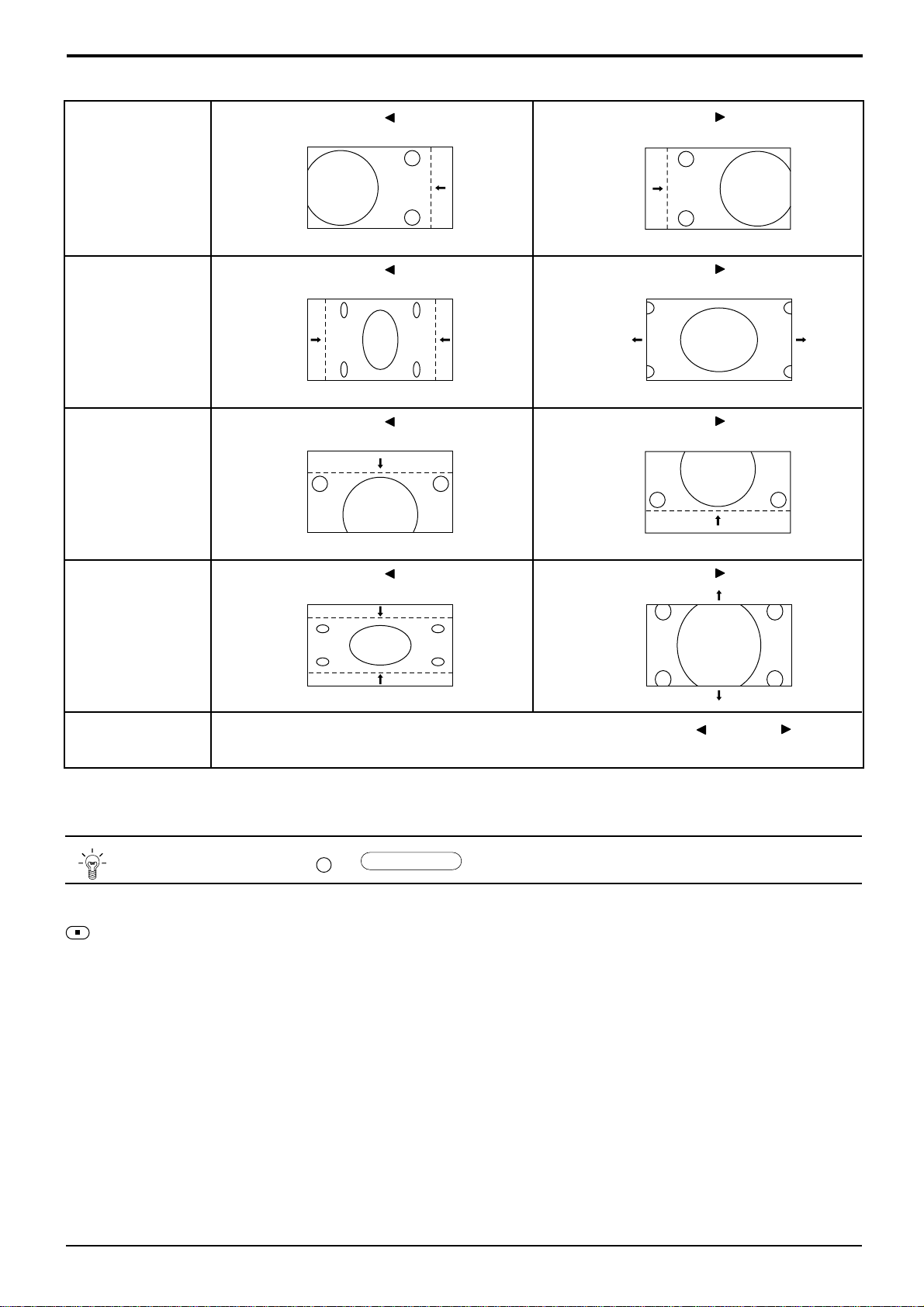
Adjusting Picture Pos./Size
H-Pos
H-Size
V-Pos
When the Position Left
When the Position Left
When the Position Left
“ ”
button is pressed.
“ ”
button is pressed.
“ ”
button is pressed.
When the Position Right
When the Position Right
When the Position Right
“ ”
button is pressed.
“ ”
button is pressed.
“ ”
button is pressed.
When the Position Left
V-Size
Clock Phase
(RGB/PC in Mode)
Flickering and distortion can be eliminated by using the Position Left
to carry out adjustment.
N
Helpful Hint ( /
While the Picture Pos./Size display is active, if either the N button on the remote control is pressed at any time or the
(ACTION button) is pressed during “Normalise”, then all adjustment values are returned to the factory settings.
“ ”
button is pressed.
Normalise
Normalisation)
When the Position Right
“ ”
“ ”
button is pressed.
or Right
“ ”
button
21
Page 94

Sound Adjustment
1
2
Bass
Adjusts low sounds
Treble
Adjusts high sounds
Balance
Adjusts left and right
volumes
SOUND
Select to adjust each item.
Press to display the Sound menu.
Press to select the desired adjustment menu.
Select the desired level by listening to the sound.
Sound
Normalise
Sound Mode
Bass
Treble
Balance
Surround
Normal
Normal
0
0
0
On
Normal
Auto
INPUT
SURROUND
VOL
N R
PICTURE
PICTURE
Emits the original sound.
Automatically controls
proper volume level.
SOUND
SET UP
Surround (see next page)
Select On or Off
To end adjustments
•
R
Press the R button
Note:
Press the SURROUND button to directly turn the surround effect On and Off. (see next page)
Bass, Treble and Surround settings are memorized separately for each Sound mode (Normal, Auto).
Helpful Hint ( /
N
While the “Sound” menu is displayed, if either the N button on the remote control is pressed at any time or the
(ACTION button) is pressed during “Normalise”, then all adjustment values are returned to the factory settings.
Normalise
Normalisation)
Mute
Useful when answering the phone or receiving unexpected visitors.
22
Press this button to mute the sound.
Press again to reactivate sound. Sound is also reactivated when power is turned off or
volume level is changed.
Page 95

Surround Controls
INPUT
SURROUND
VOL
NR
PICTURE
PICTURE
POS. /SIZE
PC
SOUND
SET UP
ASPECT
OFF TIMER
SURROUND
SURROUND Button
The benefits of surround sound are enormous. You can be
completely enveloped in sound; just as if you were at a concert
hall or cinema.
The surround setting switches on and off each time the
SURROUND button is pressed.
On Off
Surround
Note:
The surround settings are memorized separately for each Sound mode
(Normal, Auto).
On
PLASMA DISPLAY
23
Page 96

Picture Adjustments
1
2
PICTURE
Press to display the Picture menu.
Select to adjust each item.
Press to select the menu to adjust.
Select the desired level by looking at the picture
behind the menu.
Picture
Normalise
Picture Mode
Contrast
Brightness
Colour
Tint
Sharpness
White balance
Advanced settings
Press the left
select “On”. Press the down
Normal
20
or right
Normal
0
0
0
0
Normal
On
button to
enter Advanced Settings mode.
Advanced Settings On
Enables fine picture adjustment at a
professional level (see next page).
Advanced Settings
Normalise
Black extension
W/B High R
W/B High B
W/B Low R
W/B Low B
Gamma
Normal
0
0
0
0
0
2. 2
Advanced Settings Off
Displays images with settings of the
Picture menu.
button to
Picture
Normal
Normal
20
0
0
0
0
Normal
On
Press the left
or right
Normalise
Picture Mode
Contrast
Brightness
Colour
Tint
Sharpness
White balance
Advanced settings
button to switch between
modes.
Auto Normal
Cinema Dynamic
Auto
Automatically selects the mode that best suits the
brightness of the environment.
Normal
For viewing in standard (evening lighting)
environments.
This menu selects the normal levels of
Brightness and Contrast.
Dynamic
For viewing in brighter environments.
This menu selects higher than normal
Brightness and Contrast
.
levels of
Cinema
Ideal for movies.
Can be selected for AV/Component.
•
Note:
If you would like to change the picture and colour of
the selected Picture menu to something else, adjust
using the items in the Picture menu. (see next page)
Press the left
or right
button to switch between
modes.
Normal Cool Warm
N
Helpful Hint ( /
Normalise
Normalisation)
While the “Picture” menu is displayed, if either the N button on the remote control is pressed at any time or the
(ACTION button) is pressed during “Normalise”, then all adjustment values are returned to the factory settings.
24
Page 97

Picture Adjustments
Item
Contrast
Brightness
Colour
Tint
(NTSC only)
Sharpness
Note:
In PICTURE, there is not a noticeable change even when contrast is increased with a bright picture or reduced with a
dark picture.
Effect Adjustments
Selects the proper brightness and
Less More
Darker Brighter
Less More
Reddish Greenish
Less More
density for the room.
Adjusts for easier viewing of dark pictures
such as night scenes and black hair.
Adjusts colour saturation.
Adjust for nice skin colour.
Adjusts picture sharpness.
Notes:
(1)
“Colour” and “Tint”
be adjusted for “RGB” and “PC”
input signal modes.
(2) You can change the level of each
function (Contrast, Brightness,
Colour, Tint, Sharpness) for each
Picture menu.
(3) The setting details for normal,
dynamic and cinema respectively
are memorized separately for each
input mode (A V(S Video), Component,
RGB and PC).
(4) The “Tint” setting can be adjusted
for NTSC signal only during “AV
(S Video)” input signal.
settings cannot
Advanced Settings
Item
Black
extension
W/B High R
W/B High B
W/B Low R
W/B Low B
Gamma
Notes:
(1) Carry out “W/B” adjustment as follows.
A Adjust the white balance of the bright sections using the “W/B High R” and “W/B High B” settings.
B Adjust the white balance of the dark sections using the “W/B Low R” and “W/B Low B” settings.
C Repeat steps A and B to adjust.
Steps A and B affect each other’s settings, so repeat each step in turn to make the adjustment.
(2) The adjustment values are memorized separately for each input mode (AV(S Video), Component, RGB and PC).
(3) The adjustment range values should be used as an adjustment reference.
Effect
Less More
Less More
Less More
Less More
Less More
Down Up
Details
Adjusts the dark shades of the image in gradiation.
Adjusts the white balance for light red areas.
Adjusts the white balance for light blue areas.
Adjusts the white balance for dark red areas.
Adjusts the white balance for dark blue areas.
2.0
2.2
2.5
Helpful Hint ( /
N
On the remote control unit, while the “Advanced settings” menu is displayed, if either the N button is pressed at any
time or the
factory settings.
(ACTION button) is pressed during “Normalise”, then all adjustment values are returned to the
Normalise
Normalisation)
25
Page 98

Screensaver (For preventing after-images)
Do not display a still picture, especially in 4:3 mode, for any length of time.
If the display must remain on, a Screensaver should be used.
1
SET UP
2
Reversal / Scroll selection
3
Press to display the Setup menu screen.
Press to select the Screensaver.
Press to select the Screensaver screen.
Press to select the Function.
Press to select the desired function.
Setup
Component/RGB-in select
g
nal
Si
Screensaver
guag
OSD Lan
Screensaver
Function
Mode
SP Adjustment
e
En
White bar scroll
RGB
g
lish (UK
On
Off
)
On / Off selection
4
White bar scroll
Image Reversal
White bar scroll : The white bar will scroll from left to right.
Image Reversal : Negative image will be displayed on the screen.
Press to select the Mode.
Screensaver
Press to select On or Off.
Function
Mode
SP Adjustment
White bar scroll
On
Off
26
If the mode is at On, the menu screen will disappear and the Screensaver will be activated.
To stop the Screensaver under On, press the R button.
Page 99

Screensaver
Side Panel Adjustment
(For preventing after-images )
1
2
Do not display a picture in 4:3 mode for an extended period, as
this can cause an after-image to remain on the side panels either
side of the display field.
To prevent the appearance of such an after-image, illuminate the
side panels.
To display the Screensaver screen.
(Refer to the previous page, operation guide steps 1 and 2)
Press to select the SP Adjustment.
Press to select Off, Low, Mid, High.
side panel
Screen Display
after-images
Screensaver
Function
Mode
SP Adjustment
4:3
White bar scroll
On
Off
3
Off Low Mid High
R
Press to exit from Screensaver.
Notes:
(1) Setting the side panel to High mode for an extended period may result in occurrence of after-images.
(2) The side panels may flash (alternate black/white) depending on the picture being shown on the screen. In such
an occurrence, use the Cinema mode.
27
Page 100
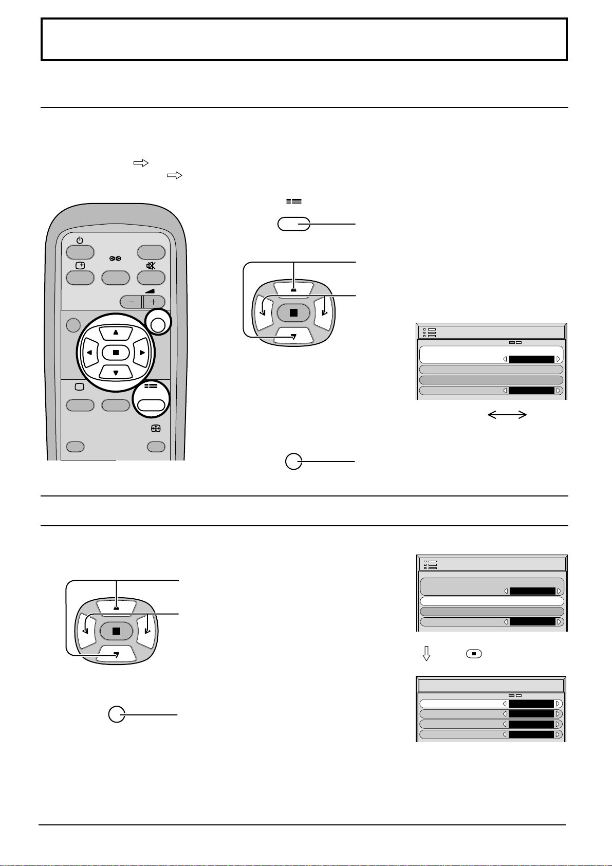
Setup for Input Signals
Component/RGB-in Select
Select the input signals to be connected by installing the Optional Terminal Board.
(Refer to the service manual for the optional Terminal Board.)
Select to match the signals from the source connected to the Component/RGB input terminals.
Y, PB, PR signals
R, G, B, HD, VD signals
“Component”
“RGB”
1
INPUT
SURROUND
2
VOL
NR
PICTURE
PICTURE
POS. /SIZE
SOUND
SET UP
ASPECT
SET UP
R
Press to display the Setup menu screen.
Press to select the “Component/RGB-in
Select”.
Press to select the desired mode.
Setup
Component/RGB-in select
g
nal
Si
Screensaver
guag
OSD Lan
e
En
RGB
g
lish (UK
Component RGB
Press to exit from adjust mode.
)
3D Y/C Filter – For NTSC AV images
Select “Signal” from the “Setup” menu during AV(S Video) input signal
mode. (“Signal [AV]” menu is displayed.)
Press to select the “3D Y/C Filter (NTSC)”
Press to set On/Off.
R
Press to exit from adjust mode.
Note:
When On, this setting only affects NTSC input signals.
Setup
Component/RGB-in select
g
nal
Si
Screensaver
guag
OSD Lan
Press
Signal
3D Y/C Filter (NTSC
Colour system
3:2 Pulldown
Aspect Auto (4:3
e
)
En
(ACTION) button
)
RGB
g
lish (UK
On
Auto
Off
4 : 3
)
[
]
AV
28
 Loading...