

Page 1

Integrated High Definition LED
Television User’s Guide:
42L6200U
47L6200U
55L6200U
47L7200U
55L7200U
If you need assistance:
Toshiba's Support Web site
Toshiba Customer Support Center:
Calling within the United States at (800) 631-3811
Calling from outside the United States at (949) 583-3050
For more information, see “Troubleshooting” on page 176 in this guide.
Owner's Record
The model number and serial number are on the back and side of your television.
Record these numbers, whenever you communicate with your Toshiba dealer
about this Television.
Model name: ______________________________________________
Serial number: _______________________________________________
Register your Toshiba Television at register.toshiba.com
support.toshiba.com
Note: To display a High Definition
picture, the TV must be receiving a
High Definition signal (such as an overthe-air High Definition TV broadcast, a
High Definition digital cable program, or
a High Definition digital satellite
program). For details, contact your TV
antenna installer, cable provider, or
satellite provider
GMA300007012
4/12
Page 2
2
Congratulations on your purchase! As you enjoy your
new product, please keep these safety tips in mind:
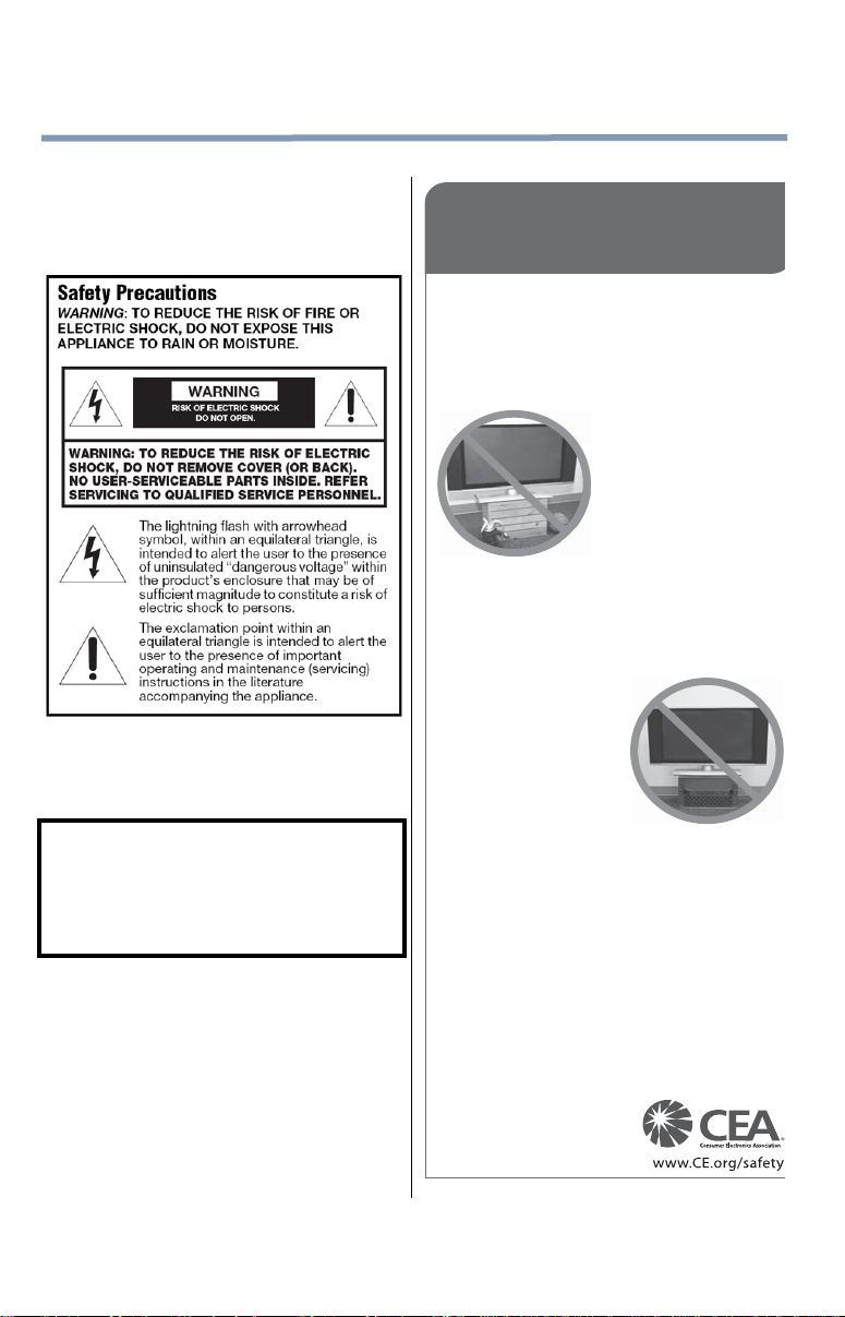
The Issue
• The home theater entertainment experience is a growing trend
and larger flat panel displays are popular purchases. However,
flat panel displays are not always supported on the proper stands
or installed according to the manufacturer’s recommendations.
• Flat panel displays that are
inappropriately situated on dressers,
bookcases, shelves, desks,
speakers, chests or carts may fall
over and cause injury.
TOSHIBA Cares!
• The consumer electronics industry
is committed to making home
entertainment enjoyable and safe.
Tune Into Safety
•
One size does NOT fit all. Follow the manufacturer’s recommendations
for the safe installation and use of your flat panel display.
• Carefully read and understand all enclosed instructions for
proper use of this product.
• Don’t allow children to climb on or play with furniture and
television sets.
• Don’t place flat panel displays on furniture
that can easily be used as steps, such
as a chest of drawers.
• Remember that children can
become excited while watching a
program, especially on a “larger
than life” flat panel display. Care
should be taken to place or install
the display where it cannot be
pushed, pulled over, or knocked down.
• Care should be taken to route all cords and
cables connected to the flat panel display so that they cannot be
pulled or grabbed by curious children.
Wall Mounting: If you decide to wall mount your
flat panel display, always:
• Use a mount that has been recommended by the display
manufacturer and/or listed by an independent laboratory (such
as UL, CSA, ETL).
• Follow all instructions supplied by the display and wall mount
manufacturers.
• If you have any doubts about your ability to safely install your
flat panel display, contact your retailer about professional
installation.
• Make sure that the wall where you are mounting the display is
appropriate. Some wall mounts are not designed to be mounted
to walls with steel studs or old cinder block construction. If you
are unsure, contact a professional installer.
• A minimum of two people are
required for installation. Flat panel
displays can be heavy.
CHILD SAFETY:
It Makes A Difference How and Where You Use Your Flat
Panel Display
Dear Customer,
Thank you for purchasing this Toshiba LED TV. This
manual will help you use the many exciting features of
your new LED TV. Before operating your LED TV,
carefully read this manual completely.
WARNING
To prevent injury, this apparatus must be securely
attached to the floor/wall in accordance with the
installation instructions. See item 26) on page 4.
WARNING: If you decide to wall mount this
television, always use a mounting bracket that has
been Listed by an independent laboratory (such as
UL, CSA, ETL) and is appropriate for the size and
weight of this television. The use of inappropriate or
non-Listed mounting brackets could result in serious
bodily injury and/or property damage. See “To
Display your LED TV using a Wall Bracket:” on
page 5.
NOTE TO CATV INSTALLERS
This is a reminder to call the CATV system installer’s
attention to Article 820-40 of the U.S. NEC, which
provides guidelines for proper grounding and, in
particular, sp ecifies that the cable ground shall be
connected to the grounding system of the building, as
close to the point of cable entry as practical. For
additional antenna grounding information, see items
33) and 34) on page 4.
Page 3
3
WARNING: NEVER expose
batteries to excessive heat such as
sunshine, fire, or the like.
DANGER: RISK OF
SERIOUS PERSONAL
INJURY, DEA TH, OR
EQUIPMENT DAMAGE!
Important Safety Instructions
1)
Read these instructions.
2)
Keep these instructions.
3)
Heed all warnings.
4)
Follow all instructions.
5)
Do not use this apparatus near water.
6)
Clean only with dry cloth.
7)
Do not block any ventilation openings. Install in
accordance with the manufacturer’s instructions.
8)
Do not install near any heat sources such as
radiators, heat registers, stoves, or other products
(including amplifiers) that produce heat.
9)
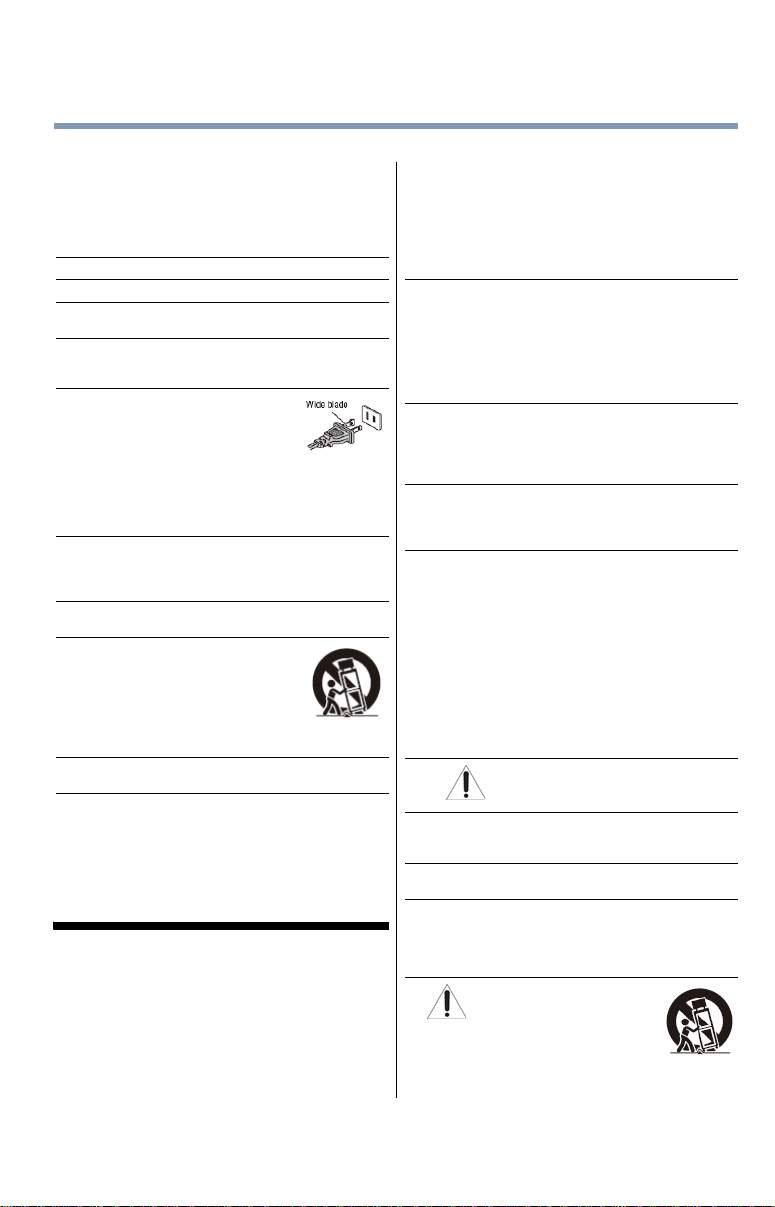
Do not defeat the safety purpose of
the polarized or grounding type
plug. A polarized plug has two
blades with one wider than the
other. A grounding type plug has
two blades and a third grounding
prong. The wide blade or the third prong are
provided for your safety. If the provided plug does
not fit into your outlet, consult an electrician for
replacement of the obsolete outlet.
10)
Protect the power cord from being walked on or
pinched, particularly at plugs, convenience
receptacles, and the point where they exit from the
apparatus.
11)
Only use attachments/a ccessories specified by
the manufacturer.
12)
Use only with the cart, stand,
tripod, bracket, or table
specified by the manufacturer,
or sold with the apparatus.
When a cart is used, use caution
when moving the cart/apparatus
combination to avoid injury from
tip-over.
13)
Unplug this apparatus during lightning storms
or when unused for long periods of time.
14)
Refer all servicing to qualified service
personnel. Servicing is required when the
apparatus has been damaged in any way , such as
power-supply cord or plug is damaged, liquid has
been spilled or objects have fallen into the
apparatus, the apparatus has been e xposed t o r ain
or moisture, does not operate normally, or has been
dropped.
Additional Safety Precautions
14a)
CAUTION: If the TV is dropped and the cabinet or
enclosure surface has been damaged or the TV
does not operate normally, take the following
precautions:
• ALW AYS turn off the TV and unplug the power cord
to avoid possible electric shock or fire.
• NEVER allow your body to come in contact with
any broken glass or liquid from the damaged
television. The LCD panel inside the TV contains
glass and a toxic liquid. If the liquid comes in
contact with your mouth or eyes, or your skin is
cut by broken glass, rinse the affected area
thoroughly with water and contact your doctor
immediately.
• ALWAYS contact a service technician to inspect
the TV any time it has been damaged or
dropped.
15)
CAUTION:
• To reduce the risk of electric shock, do not use
the polarized plug with an extension cord,
receptacle, or other outlet unless the blades ca n
be inserted completely to prevent blade
exposure.
• T o prevent electric shock, match wide blade of plug
to wide slot; fully insert.
16)
CAUTION:
• Do not let children swallow any small parts
included on or with the product or play with the
plastic bag. Keep the small parts and the plastic
bag out of the reach of children.
17)
CAUTION:
• Do not let water or other liquids come into
contact with the product, as it may result in
damage.
18)
WARNING:
• To prevent the spread of fire, keep candles or
other open flames away from this product at all
times.
• Keep the product away from direct sunlight, fire
or a heat source such as a heater. This may
reduce the product lifetime or result in fire.
Installation, Care, and Service
Installation
Follow these recommendations and precautions and
heed all warnings when installing your TV:
19)
20)
ALWAYS plug the product into an outlet that is
located in such a manner that it can be easily
unplugged in case the product requires service.
21)
NEVER route the product’s power cord inside a
wall or similar enclosed area.
22)
Never modify this equipment. Changes or
modifications may void: a) the warranty, and b) the
user’s authority to operate this equipment under
the rules of the Federal Communications
Commission.
23)
Never place the TV on an unstable
cart, stand, or table. The TV may
fall, causing serious personal injury,
death, or serious damage to the TV.
Page 4
4
WARNING: RISK OF SERIOUS
PERSONAL INJURY OR
EQUIPMENT DAMAGE!
24)
When selecting a location for the TV,
• NEVER allow any part of the TV to hang over
the edge of the supporting furniture,
• NEVER place the TV on tall furniture (for
example, entertainment centers or bookcases)
without anchoring both the furniture and the TV
to a suitable support,
• Never place cloth or other material between the
TV and the supporting furniture.
• NEVER allow children to climb on the TV
25)
To avoid damage to this product, never place or
store the TV in direct sunlight; hot, humid areas; or
areas subject to excessive dust or vibration.
26)
Always place the TV on the floor or a sturdy, level,
stable surface that can support the weight of the
unit. To secure the TV, use a sturdy strap from the
hook(s) on the rear of the TV to a wall stud, pillar,
or other immovable structure. Make sure the strap
is tight, secure, and parallel to the floor.
27)
The apparatus shall not be ex po se d t o d ripping or
splashing, and that no objects filled with liquids,
such as vases, shall be placed on the apparatus.
28)
Never block or cover the slots or openings in the
TV cabinet back, bottom, and sides. Never place
the TV:
• on a bed, sofa, rug, or similar surface;
• too close to drapes, curtains, or walls; or
• in a confined space such as a bookcase, built- in
cabinet, or any other place with poor ventilation.
The slots and openings are provided to protect the
TV from overheating and to help maintain reliable
operation of the TV. Leave a space of at least 4
(four) inches around the TV.
29)
Always leave a space of at least 4 (four) inches
around the TV. The slots and openings are
provided to protect the TV from overheat ing and to
help maintain reliable operation of the TV.
30)
Never allow anything to rest on or roll over the
power cord, and never place the TV where the
power cord is subject to wear or abuse.
31)
Never overload wall outlets and extension cords.
32)
Always operate this equipment from a 120V AC,
60 Hz power source.
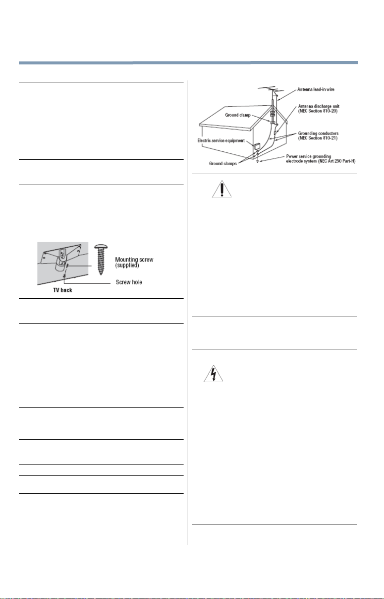
33)
Always make sure the antenna system is properly
grounded to provide adequate protection against
voltage surges and built-up static charges (see
Section 810 of the National Electric Code).
34)
DANGER: RISK OF SERIOUS
• Use extreme care to make sure you are never in
• Never attempt to install any of the following
PERSONAL INJURY OR DEATH!
a position where your body (or any item you are
in contact with, such as a ladder or screwdriver)
can accidentally touch overhead power lines.
Never locate the antenna near overhead power
lines or other electrical circuits.
during lightning activity: a) an antenna system;
or b) cables, wires, or any home theater
component connected to an antenna or phone
system.
Care
For better performance and safer operation of your
TOSHIBA TV, follow these recommendations and
precautions:
35)
If you use the TV in a room whose temperature is
32° F (0° C) or below, the picture brightness may
vary until the LCD warms up. This is not a sign of
malfunction.
36)
• Never use chemicals (such as air fresheners,
cleaning agents, etc.) on or near the TV
pedestal. Studies indicate that plastics may
weaken and crack over time from the combined
effects of chemical agents and mechanical
stress (such as the weight of the TV). Failure to
follow these instructions could result in serious
injury and/or permanent damage to TV and TV
pedestal.
• Always unplug the TV before cleaning. Gently
wipe the display panel surface (the TV screen)
using a dry, soft cloth (cotton, flannel, etc.). A
hard cloth may damage the surface of the panel.
Avoid contact with alcohol, thinner, benzene,
acidic or alkaline solvent cleaners, abrasive
cleaners, or chemical cloths, which may damage
the surface. Never spray volatile compounds
such as insecticide on the cabinet. Such
products may damage or discolor the cabinet.
37)
Never hit, press, or place anything on the back
cover. These actions will damage internal parts.
Page 5
5
WARNING: RISK OF SERIOUS
PERSONAL INJURY OR
EQUIPMENT DAMAGE!
38)
WARN ING:
RISK OF ELECTRIC SHOCK!
Never spill liquids or push objects of any kind into
the TV cabinet slots.
39)
During a lightening storm, do not touch the
connecting cables or product.
40)
For added protection of your TV from li ghtning and
power surges, always unplug the power cord and
disconnect the antenna from the TV if you leave
the TV unattended or unused for long periods of
time.
41)
Always unplug the TV to completely disconnect
from mains power. When the TV is turned of f using
the on/off switch, it is not completely disconnected
from power and a minute amount of current is still
consumed.
42)
During normal use, the TV may make occasional
snapping or popping sounds. This is normal,
especially when the unit is being turned on or off. If
these sounds become frequent or continuous,
unplug the power cord and contact a Toshiba
Authorized Service Provider.
43)
Never strike the screen with a sharp or heavy
object.
44) •
The LCD screen of this product can be damaged
by ultraviolet radiation from the sun. When
selecting a location for the television, avoid
locations where the screen may be exposed to
direct sunlight, such as in front of a window.
• Never touch, press, or place anything on the
LCD screen. These actions will damage the LCD
screen. If you need to clean the LCD screen
follow the instructions (in item 36) on page 4.
Service
WARN ING:
RISK OF ELECTRIC SHOCK!
Never attempt to service the TV yourself. Opening
and removing the covers may expose you to
dangerous voltage or other hazards. Failure to
follow this WARNING may result in death or
serious injury. Ref er all servicing not specified in
this manual to a Toshiba Authorized Service
Provider.
45)
If you have the TV serviced:
• Ask the service technician to use only
replacement parts specified by the
manufacturer.
• Upon completion of service, ask the service
technician to perform routine safety checks to
determine that the TV is in safe operating
condition.
Choosing a location for your LED TV
To Display your LCD TV on the included Pedestal
Stand:
Observe the following safety precautions:
1)
Read and follow the pedestal assembly
instructions included with the pedestal.
CAUTION: Before beginning pedestal assembly,
carefully lay the front of the LCD Panel face down
on a flat, cushioned surface such as a quilt or
blanket. Leave the bottom of the unit protruding
over the edge of the surface and assemble the
pedestal as indicated below.
Note: Extreme care should always be used when
attaching the pedestal stand to avoid damage to
the LCD panel.
2)
Place the TV on a sturdy, level surface that can
support the weight of the TV.
3)
Be sure to secure the TV to a wall, pillar, surface,
or other immovable structure see item 26) page 4
for additional details.
To Display your LED TV using a Wall Bracket:
If you decide to wall mount your LED TV , always use a
wall bracket Listed by an independent laboratory
(such as UL, CSA, ETL) that is appropriate for the size
and weight of the TV (see page 2):
1)
CAUTION: Two people are required for
installation.
2)
Unplug and remove any cables and/or other
component connectors from the rear of the TV.
3)
Remove the screws of the VESA Mounting Pattern
show in the table below.
CAUTION: Do not use the screws removed from
the back cover to attach the wall mount bracket to
the TV .
4)
Always use the screws supplied or recommended
by the wall mount manufacturer.
5)
Follow the instructions provided with your wall
bracket. Before proceeding, make sure the
appropriate bracket(s) are attached to the wall and
the back of the TV as described in the instructions
provided with the wall bracket.
6)
After attaching the appropriate bracket(s) to the
wall and the back of the TV, remove the pedestal
stand from the TV, as described below.
7)
VESA Mounting Pattern
TV Size Hole Pattern (HxV) Screw Size
42L6200U 400x400 mm M6
47L6200U 400x400 mm M6
55L6200U 400x400 mm M6
47L7200U 400x400 mm M6
55L7200U 400x400 mm M6
(unit in mm)
Page 6
6
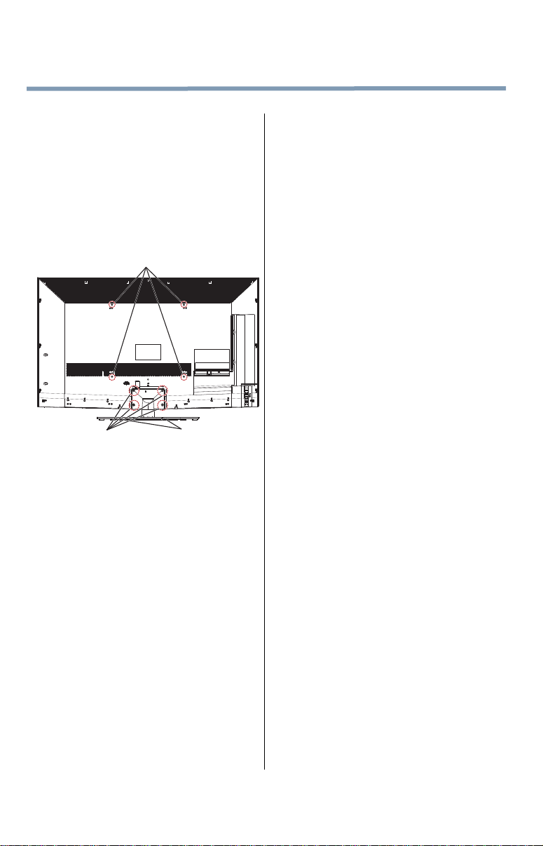
VESA Mounting Pattern
Four screws
Two clips
Removing the Pedestal Stand
1)
Carefully lay the front of the unit face down on a
flat, cushioned surface such as a quilt or blanket.
Leave the stand protruding over the edge of the
surface.
Note: Extreme care should always be used when
removing the pedestal stand to avoid damage to
the LCD panel.
2)
Remove the screws shown in the below diagram.
This will allow removal of the pedestal stand.
3)
Once you have removed all of the screws holding
the pedestal stand in place, remove the pedestal
stand from the TV.
CAUTION: Always place the TV on the floor or a
sturdy, level, stable surface that can support the
weight of the unit. Secure the TV with the
securement clip and a sturdy strap from the hooks
on the rear of the TV pedestal to a wall stud, pillar ,
or other immovable structure. Make sure the strap
is tight, secure, and parallel to the floor.
Safety Precautions for 3D glasses
About handling the 3D glasses
•
Do not repair , modify , or di sassemble the 3D glasse s
by yourself.
Doing so may cause you to become indisposed while
viewing 3D images.
CAUTION:
About the 3D glasses
•
Carefully read instructions p rovided wi th your
display and/or 3D glasses before 3D viewin g.
•
Do not use the 3D glasses if they are c racked,
broken, or not working properly.
Continuing to use them in such a state may cause
injury, eye strain, or indisposition.
•
Do not drop, exert pressu re on, or step on the 3D
glasses.
Doing so may damage the glass section which may
result in injury. Exposing the 3D glasses to liquid or
excessive heat may damage the function.
•
Do not stand or walk wh ile weari ng 3D g lasses.
You may lose your balan ce which could result in fall s
or other accidents.
•
Do not wear the 3D glasses for any purpose other
than viewing 3D programming.
3D glasses do not function as sunglasses.
•
If your nose or temple turns red, or you feel an y pai n
or discomfort, stop using the 3D glasses.
Such symptoms may occur when wearing 3D
glasses for long periods of time.
Cautions on watching the 3D images
•
Some viewers may experience a seizu re or black out
when exposed to certain flashing imag es or light s
contained in certain 3D television pictures or video
games.
Anyone who has had a seizure, loss of awareness, or
other symptom linked to an epileptic condition, or has
a family history of epilepsy, should contact a health
care professional before using the 3D function.
•
Avoid using the 3D function when under the
influence of alcohol.
•
Some individuals may experience h ealth-r elated
complications when exposed to certain 3D images.
Parents should monitor and/or supervise their children's
use of this 3D technology. If you or your child should
experience any problem, immediatel y stop using this 3D
technology and consult a physician .
•
If you are ill or feel ill, you should refrain from
viewing 3D images, and consult your health care
provider as may be appropriate.
•
If you experience any of the fo llowing symptoms
when viewing 3D video images, stop viewing and
contact your health care provider:
Convulsions, Eye or muscle twitching, Loss of
awareness, Altered vision, Involuntary movements,
Disorientation, Eye Strain, Nausea/Vomiting,
Dizziness, Headaches, Fatigue.
•
If you feel eye fatigue or other discomfort from
viewing 3D video images, stop vie wing a nd t ake a
rest until the condition improves.
•
Viewing in 3D may cause dizziness and/or
disorientation for some vi ewers.
Therefore, to avoid injury do not place your TV near
open stairwells, balconies, or wires.
Also do not sit near objects that could be broken if
accidentally hit.
•
When viewing 3D images, always wear 3D glasses.
Watching 3D images without specified 3D glasses
may cause eye strain.
•
Do not wear 3D glasses or watch 3 D image s from
steep angles or while lying down.
The 3D effect is lost in these conditions and eye
strain may result.
•
It is recommended that the viewer’s eyes and 3D
glasses are level with the screen.
•
If you have prescription eye glasses or contact
lenses, wear the 3D glasse s over them.
Watching 3D images without appropriate eyewear
may cause eye strain.
•
If 3D images often appear doubled or if you cannot
see the images in 3D, stop viewing.
Continuous viewing may cause eye strain.
Page 7
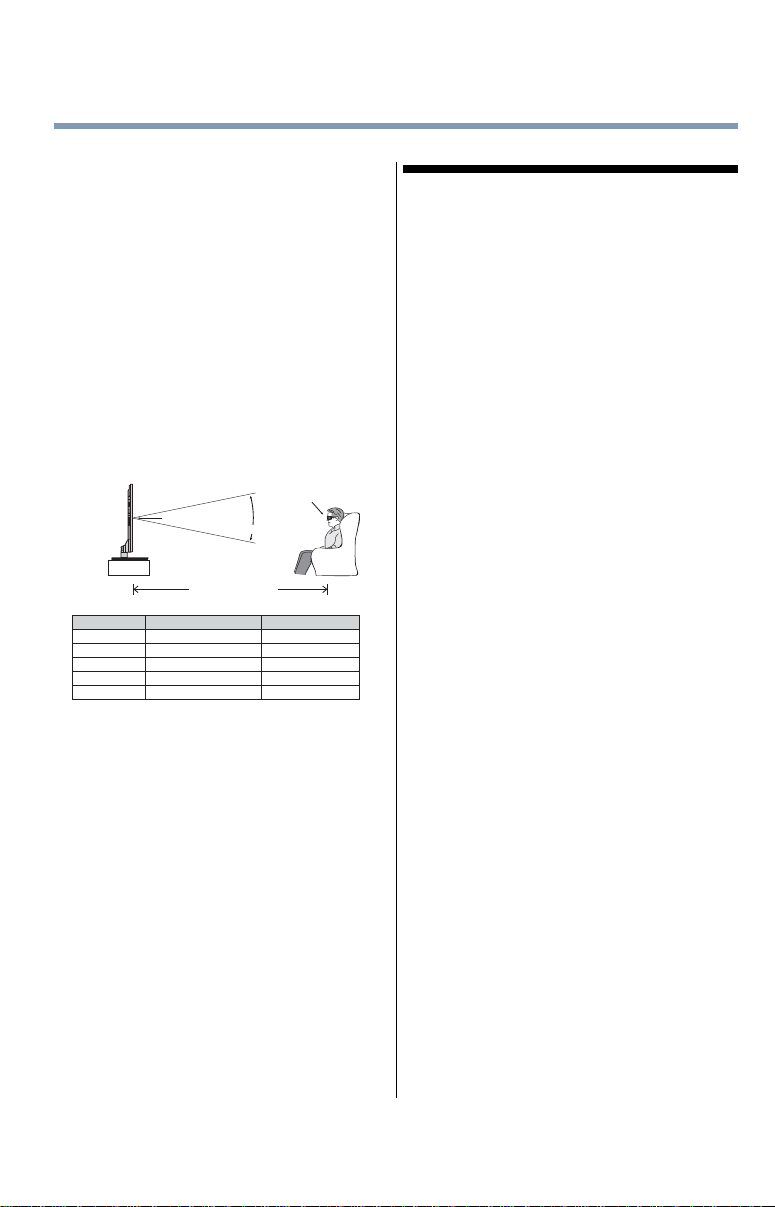
•
Center of Display
Viewing Angle
Viewing Distance
Same height as
Center of Display
Viewing angleModel Viewing distance
42L6200U
Approx. 20 degrees
Over 62 inches
47L6200U
Approx. 20 degrees
Over 69 inches
55L6200U
Approx. 20 degrees
Over 81 inches
47L7200U
Approx. 26 degrees
Over 69 inches
55L7200U
Approx. 26 degrees
Over 81 inches
Due to the possible impact on vision deve lopment,
viewers of 3D video images should b e age 6 or
above.
Children and teenagers may be more susceptible to
health issues associated with viewing in 3D and
should be closely supervised to avoid prolonged
viewing without rest.
•
Watching TV while sitting too close to the screen for
an extended period of time may cause eye strain.
•
For optimal 3D effect and to avoid eye fatigue it is
important that you properly select your viewing
position.
The best viewing position is at the indicated viewing
distance with your eyes at the same level as the
center of the display as shown below. The center of
the optimum viewing area varies from set to set. The
usable viewing area is generally over the range
shown in the table below (actual angle not depicted
in drawing).
Important: If you see a double image, your eyes are
either too high or too low in relation to the horizontal
center of the screen. Adjust your position so that it is
closer to the center to avoid eye fatigue and to enjoy
optimum 3D effects.
7
FCC Declaration of Conformity
Compliance Statement (Part 15):
Toshiba television models 42L6200U, 47L6200U,
55L6200U, 47L7200U, and 55L7200U comply with Part
15 of the FCC Rules.
Operation is subject to the following two conditions:
(1) This device may not cause harmful interference, and
(2) This device must accept any interference received,
including interference that may cause undesired operation.
The party responsible for compliance to these rules is:
Toshiba America Information Systems, Inc.
9740 Irvine Blvd., Irvine, CA 92618.
Ph: 800-631-3811
Note: This equipment has been tested and found to
comply with the limits for a Class B digital device,
pursuant to Part 15 of the FCC Rules. These limit s are
designed to provide reasonable protection against
harmful interference in a residential installation. This
equipment generates, uses, and can radiate radio
frequency energy and, if not installed and used in
accordance with the instructions, may cause harmful
interference to radio communications. However, there
is no guarantee that interference will not occur in a
particular installation. If this equipment does cause
harmful interference to radio or television reception,
which can be determined by removing and applying
power to the equipment, the user is encouraged to try
to correct the interference by one of the following
measures:
•
Reorient or relocate the receiving antenna.
•
Increase the separation between the equipment and
receiver.
•
Connect the equipment into an outlet on a circuit different
from that to which the receiver is connected.
•
Consult the dealer or an experienced radio/TV technician
for help.
Caution: Changes or modifications to this equipment
not expressly approved by Toshiba could void the
user's authority to operate this equipment.
Wireless Radio
For product available in the USA/Canada market, only channel
1–11 can be operated. Selection of other channels is not possible.
The device could automatically discontinue transmission in case
of absence of information to transmit, or operational failure.
Note that this is not intended to prohibit transmission of control
or signaling information or the use of repetitive codes where
required by the technology. If this device is going to be operated
in 5.15–5.25GHz frequency range, then it is restricted to an
indoor environment only.
Important: Any changes or modifications not expressly
approved by the party responsible for compliance could
void the user's authority to operate this equipment. This
device and its antenna(s) must not be co-located or
operating in conjunction with any other antenna or
transmitter.
Page 8

8
FCC Radiation Exposure Statement: This
equipment complies with FCC radiation exposure
limits set forth for an uncontrolled environment. This
equipment should be installed and operated with
minimum distance 20cm between the radiator & your
body.
Canada - Industry Canada Statement
This device complies with RSS-210.
Operation is subject to the following two conditions:
(1) This device may not cause harmful interference, and
(2) This device must accept any interference received,
including interference that may cause undesired operation
of the device.
This device and its antenna(s) must not be co-located or
operating in conjunction with any other antenna or
transmitter.
Wireless Radio
For product available in the USA/Canada market, only
channel 1–11 can be operated. Selection of other channels is
not possible.
The device could automatically discontinue transmission in
case of absence of information to transmit, or operational
failure. Note that this is not intended to prohibit
transmission of control or signaling information or the use
of repetitive codes where required by the technology.
Important: Any changes or modifications not
expressly approved by the party responsible for
compliance could void the user's authority to operate
this equipment.
IMPORTANT NOTE:
IC Radiation Exposure Statement: This equipment
complies with IC RSS-102 radiation exposure limits
set forth for an uncontrolled environment. This
equipment should be installed and operated with
minimum distance 20cm between the radiator & your
body.
ENERGY STAR® User Information
ENERGY STAR User Information Statement: the factory
default settings of this television meet ENERGY STAR
requirements. Changing Picture Settings may increase
energy consumption, possibly beyond the limits required
for ENERGY STAR qualification.
To ensure your television is operating at optimal energy
efficiency, select [Home] mode during initial activation. To
return to [Home] mode settings, select [AutoView] picture
mode. [AutoView] mode is recommended for normal home
use.
®
ENERGY STAR
that earn the ENERGY STAR prevent
green house gas emissions by meeting
strict guidelines set by the U.S.
Environmental Protection Agency.
ENERGY STAR and the ENERGY STAR
mark are registered U.S. marks.
qualified TV. Products
®
Important notes about your TV
The following symptoms are technical limitations of
LCD Display technology and are not an indication of
malfunction; therefore, Toshiba is not responsible for
perceived issues resulting from these symptoms.
1)
An afterimage (ghost) may appear on t he scr een if
a fixed, non-moving image appears for a long
period of time. The afterimage is not permanent
and will disappear in a short period of time.
2)
The LCD panel contained in this TV is
manufactured using an extremely high level of
precision technology; however, there may be an
occasional pixel (dot of light) that does not operate
properly (does not light, remains constantly lit,
etc.). This is a structural property of LCD
technology, is not a sign of malfunction, and is not
covered under your warranty. Such pixels are not
visible when the picture is viewed from a normal
viewing distance.
Note: Interactive video games that involve shooting a
“gun” type of joystick at an on-screen target may not
work with this TV.
Page 9
Trademark Information
powered
by
•
Cinema Series, ClearScan, ColorStream, Dynalight,
GameTimer, Native Mode, Surflock, and Trivector are
trademarks or registered trademarks of Toshiba America
Information Systems, Inc. and/or Toshiba Corporation.
•
Android and Google Play are trademar ks of Google Inc.
•
Audyssey EQ® provides clear, accurate
technology ensures you enjoy your audio experience as
much as your video.
frequency monitoring to extend the range and bass of
small speakers. This enables the system to produce
lower frequencies than would be possible with a
traditional system of the same size.
consistent sound level between television progr ams,
commercials, and between the loud and soft passages of
movies.
while blocking distortion, so your TV gets loud and still
sounds great.
problems caused by small speakers and drivers.
Working together these technologies deliver a better
translation of the audio content and make the television
experience sound closer to the original.
•
Manufactured under license from Audyssey
Laboratories, Inc. U.S. and foreign patents pending.
Audyssey EQ®, Audyssey ABX™, Audyssey Dynamic
Volume®, Audyssey V olume Extension™, and
Audyssey Premium T elevision™ are r egistered and
licensed trademarks of Audyssey Laboratories, Inc.
•
Blu-ray Disc™, Blu-ray™, and the logos are trademarks
of the Blu-ray Disc Association
•
CinemaNow is a registered tradem ark of Best Buy, Inc.
•
ENERGY STAR and the ENERGY ST AR mark are
registered U.S. marks.
symbol are trademarks of Dolby Laboratories.
•
HDMI, the HDMI Logo, and High-Definition Multimedia
Interface are trademarks or registered trademarks of
HDMI Licensing LLC in the United States and other
countries.
•
IOS is a registered trademark or trademark of Cisco
Systems, Inc. and/or its affiliates in the United States and
certain other countries.
and natural sound right out of the box. This
•
Audyssey ABX™ technology uses
sophisticated driver analysis and lo w
•
Audyssey Dynamic Volume®
automatically adjusts volume to provide a
•
Audyssey Volume Extension™ doubles
the volume capability in small speakers
•
Audyssey Premium T elevision™ is a suite
of technologies that remove the acoustical
•
Manufactured under license f rom Dol by
Laboratories. Dolby and the double-D
•
www.espial. com
•
iTunes Store is a trademark of Apple Inc., registered in
the U.S. and other countries.
•
MPEG Layer-3 audio coding technology licensed from
Fraunhofer IIS and Thomson.
•
Netflix is a registered trademark of Netflix, Inc.
•
Rovi is a trademark of Rovi Corporation
system is manufactured under license from Rovi
Corporation and/or its subsidiaries.
•
VUDU, Vudu Apps, and Vudu Movies are licensed and
registered trademarks of VUDU, Inc
•
YouT ube is a registered trademark of Google Inc.
Portions © UEI 2000-2012.
•
THIS PRODUCT IS LICENSED UNDER THE AVC
PA TENT PORTFOLIO LICENSE FOR THE PERSONAL
AND NONCOMMERCIAL USE OF A CONSUMER T O
(i) ENCODE VIDEO IN COMPLIANCE WITH THE AVC
STANDARD
(“AVC VIDEO”) AND/ OR (ii) DECODE AVC VIDEO
THAT W AS ENCODED BY A CONSUMER ENGAGED
IN A PERSONAL AND NON-COMMERCIAL ACTIVITY
AND/OR WAS OBTAINED FROM A VIDEO PROVIDER
LICENSED TO PROVIDE A V C VIDEO. NO LICENSE IS
GRANTED OR SHALL BE IMPLIED FOR ANY OTHER
USE. ADDITIONAL INFORMATION MA Y BE
OBTAINED FROM MPEG LA, LLC. SEE HTTP://
WWW.MPEGLA.COM
•
THIS PRODUCT IS LICENSED UNDER THE VC-1
PA TENT PORTFOLIO LICENSE FOR THE PERSONAL
AND NONCOMMERCIAL USE OF A CONSUMER T O
(i) ENCODE VIDEO IN COMPLIANCE WITH THE VC-1
STANDARD
(“VC-1 VIDEO”) AND/OR (ii) DECODE VC-1 VIDEO
THAT W AS ENCODED BY A CONSUMER ENGAGED
IN A PERSONAL AND NON-COMMERCIAL ACTIVITY
AND/OR WAS OBTAINED FROM A VIDEO PROVIDER
LICENSED TO PROVIDE VC-1 VIDEO. NO LICENSE
IS GRANTED OR SHALL BE IMPLIED FOR ANY
OTHER USE. ADDITIONAL INFORMATION MAY BE
OBTAINED FROM MPEG LA, LLC. SEE HTTP://
WWW.MPEGLA.COM
•
THIS PRODUCT IS LICENSED UNDER THE MPE G-4
VISUAL PATENT PORTFOLIO LICENSE FOR THE
PERSONAL AND NON-COMMERCIAL USE OF A
CONSUMER FOR (i) ENCODING VIDEO IN
COMPLIANCE WITH THE MPEG-4 VISUAL
STANDARD (“MPEG-4 VIDEO”) AND/OR (ii)
DECODING MPEG-4 VIDEO THAT WAS ENCODED
BY A CONSUMER ENGAGED IN A PERSONAL AND
NON-COMMERCIAL ACTIVITY AND/OR WAS
OBTAINED FROM A VIDEO PROVIDER LICENSED
BY MPEG LA TO PROVIDE MPEG-4 VIDEO. NO
LICENSE IS GRANTED OR SHALL BE IMPLIED FOR
ANY OTHER USE. ADDITIONAL INFORMATION
INCLUDING THAT RELATING TO
PROMOTIONAL,INTERNAL AND COMMERCIAL
USES AND LICENSING MAY BE OBTAINED FROM
MPEG LA,LLC. SEE HTTP:// WWW.MPEGLA.COM
and/or its subsidiaries. The Rovi Guide
•
Designed with UEI Technology™. Under
License from Universal Electronics inc.
9
Page 10

10
Copyright
This guide is copyrighted by Toshiba America Information
Systems, Inc. with all rights reserved. Under the copyright
laws, this guide cannot be reproduced in any form without
the prior written permission of Toshiba. No patent liability
is assumed, however, with respect to the use of the
information contained herein.
©2012 by Toshiba America Information Systems, Inc. All
rights reserved.
Notice
The information contained in this manual, including but not
limited to any product specifications, is subject to change
without notice.
TOSHIBA CORPORATION AND TOSHIBA
AMERICA INFORMATION SYSTEMS, INC.
(TOSHIBA) PROVIDES NO WARRANTY WITH
REGARD TO THIS MANUAL OR ANY OTHER
INFORMATION CONTAINED HEREIN AND
HEREBY EXPRESSLY DISCLAIMS ANY IMPLIED
WARRANTIES OF MERCHANTABILITY OR
FITNESS FOR ANY PARTICULAR PURPOSE WITH
REGARD TO ANY OF THE FOREGOING. TOSHIBA
ASSUMES NO LIABILITY FOR ANY DAMAGES
INCURRED DIRECTLY OR INDIRECTLY FROM
ANY TECHNICAL OR TYPOGRAPHICAL ERRORS
OR OMISSIONS CONTAINED HEREIN OR FOR
DISCREPANCIES BETWEEN THE PRODUCT AND
THE MANUAL. IN NO EVENT SHALL TOSHIBA BE
LIABLE FOR ANY INCIDENTAL,
CONSEQUENTIAL, SPECIAL, OR EXEMPLARY
DAMAGES, WHETHER BASED ON TORT,
CONTRACT OR OTHERWISE, ARISING OUT OF
OR IN CONNECTION WITH THIS MANUAL OR
ANY OTHER INFORMATION CONTAINED HEREIN
OR THE USE THEREOF.
Page 11

Contents
Chapter 1: Introduction.............................................................. 20
Features ..................................................................21
Overview of installation, setup, and use..................22
TV front and side panel controls & connections .....23
Front panel........................................................23
Left side ............................................................23
TV back panel controls and connections.................24
Back panel controls...........................................25
Back panel connections ....................................25
Chapter 2: Connecting Your TV................................................ 27
Overview of cable types ..........................................27
Coaxial cable (F-type) .......................................27
Standard A/V cables (red/white/yellow) ............27
Component video cables (red/green/blue) ........28
HDMI® cable (with HDMI Logo)........................28
Dual-wand IR blaster cable ...............................29
Optical audio cable............................................29
Analog RGB (15-pin) computer cable ...............29
3.5mm Stereo to RCA Y-cable ..........................29
11
Page 12

12
Contents
LAN cable..........................................................29
About the connection illustrations ....................30
Connecting an antenna, satellite receiver,
and cable TV box ..............................................30
Connecting DVD to ColorStream® or VCR to
composite video................................................31
Connecting remote IR devices ................................32
Using the IR blaster OUT terminal ....................32
Connecting a digital audio system ..........................34
Connecting an HDMI® or DVI device
to the HDMI® input ..........................................35
Using the TV remote and HDMI® CEC Control
to control other devices ....................................37
Connecting an HDMI® audio system......................38
Connecting a computer...........................................39
Connecting a computer to
the TV’s PC IN terminal:..............................39
Connect a computer to
the TV’s HDMI® terminal............................41
Connecting to a home network ...............................42
Connecting the TV directly to a computer
without an Internet connection ...................42
Connecting the TV to a home network
without an Internet connection ...................42
Connecting the TV to a home network with an
Internet connection - wired.........................43
Connecting the TV to a home network with an
Internet connection - wireless.....................44
Chapter 3: Using the Remote Control...................................... 46
Controlling other devices ........................................46
Installing batteries ..................................................46
Remote control effective range ...............................48
Learning about the remote control..........................49
Page 13

Contents
13
Chapter 4: Initial Setup and Menu............................................ 51
Initial setup .............................................................51
Performing the initial setup...............................52
IR Blaster Setup......................................................55
Network Setup ........................................................58
MediaGuide Setup...................................................59
Navigating the menu system...................................61
Main menu layout ...................................................62
Quick Menu.............................................................63
Chapter 5: Setting up your TV .................................................. 64
How to navigate the menu ......................................64
Changing initial settings....................................64
Individual settings.............................................65
Storing channels in memory (optional).............66
Skipping channels.............................................68
Skipping video inputs .......................................68
Labeling analog TV channels ............................69
Labeling video inputs........................................70
Configuring shared inputs.................................70
Setting the Auto Input feature ...........................70
Chapter 6: Basic features........................................................... 72
Viewing 3D images .................................................72
Using 3D functions .................................................74
Switching display mode or
selecting 3D format.....................................76
The 3D button operation ...................................76
Switching to 3D mode ......................................77
Selecting 3D format from
the Quick menu in 3D mode........................78
Switching to 2D mode ......................................79
Selecting 2D format from
the Quick menu in 2D mode........................79
Switching to Native mode .................................80
Setting the auto start mode...............................81
Page 14

14
Contents
Setting the 3D PIN code..........................................81
Enter a new PIN code........................................81
Change or delete your PIN code........................82
Forgotten PIN codes .........................................82
Setting the 3D start message............................82
Setting the 3D Lock ..........................................83
Setting the 3D Timer Lock ................................83
Setting the Enable 3D Timer .............................83
Displaying 3D Important Information................84
Adjusting 2D to 3D depth..................................84
Switching left and right images.........................85
Tuning Channels .....................................................85
Tuning to the next programmed channel ..........85
Tuning to a specific channel (programmed or
unprogrammed)..........................................85
Using Channel Return .......................................85
Using SurfLock™ ....................................................85
Selecting the video input to view ............................86
Using closed captions.............................................87
Analog CC mode ...............................................87
Digital CC settings.............................................89
Setting the PIN code .........................................90
Entering a new PIN code...................................91
Changing or deleting your PIN code .................91
Forgotten PIN code ...........................................91
Using parental controls...........................................91
Blocking TV programs and movies
by rating (V-Chip) .......................................91
Downloading an additional rating system .........92
Displaying ratings .............................................95
Unlocking programs .........................................95
Locking specific channels .......................................95
Locking video inputs.........................................96
Setting a time limit for games...........................96
Locking the control panel..................................97
Using HDMI® CEC Control ......................................97
Page 15

Contents
15
Controlling HDMI® CEC playback devices .........98
HDMI® CEC Control input source selection.....100
Adjusting the amplifier’s audio........................100
Other HDMI® CEC Control functions ...............101
Using the HDMI® RGB Range feature ..................101
Viewing the HDMI® signal information ................102
Using your computer with the TV .........................102
Adjusting the image ........................................102
Setting the computer audio.............................103
Setting the timer to turn on the TV........................104
Setting the sleep timer ..........................................105
Setting No Signal Power Down .............................106
Displaying TV status information ..........................106
Viewing support information.................................107
Resetting to Factory Defaults ................................107
Power failure.........................................................108
Chapter 7: Picture and Sound Controls................................. 109
Selecting the picture size ......................................109
Native..............................................................110
4:3 ..................................................................111
Full..................................................................111
TheaterWide 1.................................................112
TheaterWide 2.................................................112
TheaterWide 3.................................................112
Normal............................................................113
Dot by Dot.......................................................113
Scrolling the picture..............................................113
Using the Auto Aspect feature...............................114
Using the 4:3 Stretch ............................................114
Adjusting the picture.............................................115
Selecting the picture mode .............................115
Adjusting the picture quality ...........................115
Using the advanced picture settings features........117
Edge Enhancer ................................................117
Dynamic Contrast ...........................................117
Page 16

16
Contents
DynaLight®......................................................118
Static Gamma .................................................118
ClearScan
Cinema Mode..................................................119
MPEG NR........................................................119
DNR ................................................................119
Auto Brightness Sensor ..................................120
Backlight Adjustment Pro ...............................120
ColorMaster™ .................................................121
Base Color Adjustment ...................................121
Color temperature...........................................122
Resetting to the factory default .......................122
Setting the expert picture settings ........................122
Test Pattern ....................................................122
RGB Filter........................................................123
White Balance .................................................123
Locking the picture settings..................................124
Adjusting the audio ...............................................125
Muting the sound............................................125
Selecting stereo/SAP broadcasts ....................125
Adjusting the audio balance ............................125
Adjusting the range.........................................126
Selecting the optical audio output format .......126
Using the Dolby® Digital
Audyssey Premium Television™ ....................127
Using Audyssey EQ® for
Using Audyssey Dynamic Volume ® ..............127
Audyssey ABX™..............................................128
Using the surround sound feature ........................128
®.............................................................................................. 118
Dynamic Range Control feature ................126
Wall Mounted or Table-top TVs ...............127
Chapter 8: Advanced features................................................. 129
Using your home network.....................................129
When using a Wireless network connection ...130
Setting up the Network .........................................131
Page 17

Contents
17
Wireless Setup................................................131
Advanced Network Setup................................136
DNS Setup ......................................................137
Network Connection Test................................139
Using the software keyboard ................................139
Enter text using the keypad.............................139
Enter text using the full keyboard....................139
Performing a Software Upgrade............................140
Viewing the Software Licenses .............................141
Using the SmartTV features ..................................142
eMANUAL .......................................................142
ePORTAL page ...............................................142
ePORTAL SearchAll ........................................142
ePORTAL Apps ...............................................144
Netflix
VUDU™...........................................................145
YouTube™ ......................................................146
CinemaNow® .................................................147
ePORTAL Internet ...........................................147
ePORTAL Messages........................................151
ePORTAL Events.............................................151
ePORTAL Favorite Sites ..................................152
Edit ePORTAL Favorites ..................................152
ePORTAL Preferences.....................................153
MediaGuide.....................................................153
ePORTAL MediaShare (Videos, Music,
MediaShare (Media Player) specifications ......157
Basic operation ...............................................158
Viewing movie files .........................................160
Playing music files..........................................162
Viewing photo files .........................................164
Search...................................................................166
Network Device Setup...........................................167
External Control Setup ....................................167
Setting up the Media Renderer feature............168
®........................................................................................................144
and Photos) ..............................................157
Page 18

18
Contents
Chapter 9: Apps Collaboration................................................ 171
Using Apps on a Tablet or Smartphone ................171
Apps Control Profile..............................................172
Initial setup ...........................................................173
Toshiba A/V Remote App ......................................174
Toshiba Send & Play App .....................................174
Toshiba MediaGuide .............................................174
TV listings.......................................................175
Movies/TV portal screen .................................175
Search screen .................................................175
Detailed information........................................175
Chapter 10: Troubleshooting................................................... 176
General troubleshooting........................................176
Picture problems ..................................................177
Sound problems ...................................................179
Remote control problems .....................................179
Channel tuning problems......................................179
Closed caption problems ......................................180
Rating blocking (V-Chip) problems.......................180
HDMI® CEC Control operation...............................180
HDMI® problems .................................................181
Network problems ................................................181
Wireless network problems ..................................183
MediaShare (Media Player) problems...................183
Light Indicator .....................................................184
Power On/Standby light ..................................184
If the problem persists after trying solutions ........185
Appendix A: Specifications...................................................... 186
Television system .................................................186
Channel coverage..................................................186
Power source........................................................187
Power consumption........................................187
Audio power..........................................................187
Speaker type .........................................................187
Page 19

Contents
19
Video/audio terminals ...........................................188
Video/audio input............................................188
ColorStream® (component video) HD input...188
HDMI® input ..................................................188
Digital audio output.........................................188
PC input ..........................................................188
Wireless connection..............................................188
Ethernet ..........................................................189
USB.................................................................189
Dimensions with table stand.................................189
Mass (weight).................................................189
Operating conditions.......................................189
Supplied accessories ............................................190
Acceptable signal formats for PC IN,
HDMI®, and 3D..............................................191
PC IN signal formats.......................................191
HDMI® signal formats....................................192
3D Signal formats* .........................................193
Operating the TV with combination buttons..........194
Index..........................................................................................196
Page 20

Chapter 1
NOTE
Introduction
Safety icons
This manual contains safety instructions that must be observed to avoid potential
hazards that could result in personal injuries, damage to your equipment, or loss
of data. These safety cautions have been classified according to the seriousness of
the risk, and icons highlight these instructions as follows:
Indicates an imminently hazardous situation which, if not avoided, will result
in death or serious injury.
Indicates a potentially hazardous situation which, if not avoided, could result
in death or serious injury.
Indicates a potentially hazardous situation which, if not avoided, may result
in minor or moderate injury.
Indicates a potentially hazardous situation which, if not avoided, may result
in property damage.
Provides important information.
20
Page 21

Features
❖ Integrated digital tuning (8VSB ATSC and QAM)—
❖ 1920 x 1080 output resolution.
❖ Four HDMI
❖ HDMI
❖ HDMI
❖ ColorStream
❖ Digital Audio Out—Optical audio connection with Dolby
❖ PC IN (Analog RGB)—Computer terminal, see “Connecting
❖ IR Blaster Out— Controls infrared remote controlled devices
❖ Built-in WLAN—Allows the television to access your home
❖ ColorMaster™—Allows you to adjust the TV’s standard
❖ ClearScan
❖ AutoView
❖ Dynamic Volume (Audyssey Dynamic Volume
❖ MediaShare (Media Player)—Allows you to view photo files
Introduction
Features
21
Eliminates the need for a separate digital converter set-top box
(in most cases).
®
—Digital, High-Definition Multimedia
Interfaces with 1080p input support
®
capabilities
ARC (Audio Return Channel)—Enables the audio signal of
the TV to be sent to an AV amplifier via an HDMI
®
cable.
RGB Range—Adjusts RGB full range signal automatically.
®
CEC Control—Allows control of external devices
from the TV remote via HDMI
®
HD—High-resolution component video input.
®
connection
®
Digital optical output format, see “Connecting a digital audio
system” on page 34.
a computer” on page 39.
from the TV.
wireless network without an external Dual Band WLAN
Adapter.
colors, see “ColorMaster™” on page 121.
®
—Provides picture clarity for fast motion video
using new Backlight Scanning technology.
®
—Allows you to automatically adjust picture
settings based on ambient light conditions and input signal
content, see “ENERGY STAR® User Information” on page 8.
®
)—
Eliminates inconsistent TV volume when changing channels or
viewing commercials, see “Audyssey Premium Television™”
on page 127.
and play music or movie files, see “ePORTAL MediaShare
(Videos, Music, and Photos)” on page 157.
Page 22

22
Introduction
Overview of installation, setup, and use
❖ 3D capability—Allows you to view and experience 3D
content on the television while using special glasses.
❖ ENERGY STAR
®
qualified
Overview of installation, setup, and use
Follow these steps to set up your TV and begin using its many
exciting features.
1 Carefully read the important safety, installation, care, and
service information. Keep this manual for future reference.
2 To choose a location for the TV:
❖ Read “Important notes about your TV” on page 8.
❖ Place the TV on the floor or a sturdy, level, stable surface
that can support the weight of the unit. Secure the TV to a
wall, pillar, or other immovable structure, see 24) on
page 4.
❖ Place the TV in a location where light does not reflect on
the screen.
❖ Place the TV far enough from walls and other objects to
allow proper ventilation. Inadequate ventilation may cause
overheating, which will damage the TV. THIS TYPE OF
DAMAGE IS NOT COVERED UNDER THE TOSHIBA
WARRANTY.
3 Do not plug in any power cords until after you have connected
all cables and devices to your TV.
4 Before connecting cables or devices to the TV, learn the
functions of the TV’s connections and controls, see “Overview
of cable types” on page 27.
5 Connect your other electronic device(s) to the TV, see
“Connecting Your TV” on page 27.
6 Install the batteries in the remote control, see “Installing
batteries” on page 46
7 See “Using the Remote Control” on page 46 for an overview of
the buttons on the remote control.
8 After connecting all cables and devices, plug in the power
cords for your TV and other devices. Then press the POWER
button on the TV control panel or remote control to turn on the
TV. If the TV stops responding to the buttons on the remote
control or TV control panel and you cannot turn the TV off or
Page 23
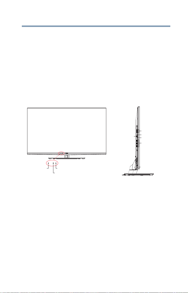
Introduction
Brightness sensor Remote sensor
Power LED
Digital Audio
jack
2 USB ports
3 HDMI
®
ports
1 IR Blaster Out
1 Analog Audio port
TV front and side panel controls and connections
on, unplug the power cords for a few seconds and then plug
them in and try again.
9 See “Navigating the menu system” on page 61 for a quick
overview of navigating the TV’s menu system.
10 Program channels into the TV’s channel memory, see “Au to
Tuning” on page 66.
11 For details on using the TV’s features, see chapters 6, 7, and 8.
12 For help, refer to “Troubleshooting” on page 176.
13 For technical specifications, see “Specifications” on page 186.
TV front and side panel controls and connections
23
(Sample Illustration) L6200U/L7200U Series front and side panel
controls and connections
Front panel
1 Power On/Standby LED—Power indicator light, (glows
green when the TV power is On).
2 Brightness Sensor—This sensor detects the ambient light
conditions to optimize the backlighting levels, see “Auto
Brightness Sensor” on page 120.
3 Remote Sensor—Point the remote control toward this remote
sensor, see “Remote control effective range” on page 48.
Left side
4 2 USB Ports—Used to access video, music, or photo files with
USB device.
Page 24
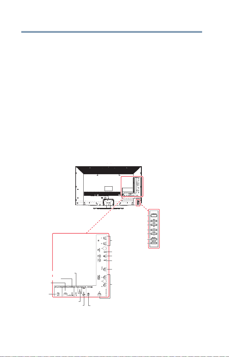
24
Back
HDMI 4HDMI 4
HDMI 3HDMI 3
PC / COLOR STREAM HD 2PC / COLOR STREAM HD 2
COLOR COLOR
STREAM STREAM
HD 1HD 1
VIDEO 2VIDEO 2
ColorStream® HD
Analog Audio OUT
Digital Audio OUT
IR Blaster OUT
Antenna/Cable
Video 1 IN
Video 2 IN
USB ports
HDMI
®
IN ports
PC/HDMI
®
IN
PC IN
LAN
ARC HDMI® only port
Menu button
Input button
Power button
Volume Up
Volume Down
Channel Up
Channel Down
TV back panel controls and connections
5 IR Blaster OUT—Used to connect and control infrared
remote-controlled devices.
6 Digital Audio Jack—Optical audio output in Dolby
Introduction
or PCM (pulse-code modulation) format for connecting an
external Dolby
®
Digital decoder, amplifier, A/V receiver, or
home theater system with optical audio input.
7 Analog Audio Port—Analog audio outputs for connecting an
audio amplifier.
8 3 HDMI Ports—High-Definition Multimedia Interface input
receives digital audio and uncompressed digital video from an
®
HDMI
device. HDMI
device or uncompressed digital video from a DVI
®
connection is necessary to receive 1080p
signals.
TV back panel controls and connections
For explanations of cable types and connections, see “Connecting
Your TV” on page 27.
®
Digital
(Sample Illustration) L6200U/L7200U Series back panel controls
and connections
Page 25

TV back panel controls and connections
Back panel controls
1 POWER—Turns the TV On and Off.
2 VOL +- —Adjusts the volume level. When an on-screen menu
appears, these keys function as ( / ) menu navigation
buttons.
3 CH Up/Down arrow buttons—Changes the channel. When
an on-screen menu appears, these buttons function as ( / )
menu navigation buttons.
4 MENU—Accesses the menu. When an on-screen menu
appears, the MENU button on the TV’s control panel functions
as the BACK button.
5 INPUT—Changes the source you are viewing. When an on-
screen menu appears, the INPUT button on the TV’s control
panel functions as the OK button.
Back panel connections
6 LAN IN—Connects the TV to your home network.
7 PC/ColorStream HD2 IN—For use when connecting a
personal computer.
8 PC/HDMI-4 (Audio) IN—PC audio input terminals are
shared with HDMI
use can be configured in the Configuring shared inputs menu,
see “Configuring shared inputs” on page 70.
9 ColorStream
connections, see “Connecting DVD to ColorStream
to composite video” on page 31.
10 Video 2 IN—Video input.
11 Video 1 IN—Video input.
12 ANT/CABLE—Antenna input that supports analog (NTSC)
and digital (ATSC) off-air antenna signals and analog and
digital Cable TV (QAM) signals.
13 HDMI
14 ARC HDMI
®
IN—High-Definition Multimedia Interface input
receives digital audio and uncompressed digital video from an
®
HDMI
device or uncompressed digital video from a DVI
device. HDMI
signals.
enables the audio signal of the TV to be sent to an AV amplifier
via the HDMI cable.
Introduction
®
-4 analog audio input terminals, and their
®
HD1 IN—These include standard A/V
®
connection is necessary to receive 1080p
®
only port—Audio Return Channel (ARC)
®
or VCR
25
Page 26

26
NOTE
Introduction
TV back panel controls and connections
15 Analog Audio OUT—Analog audio outputs for connecting an
audio amplifier.
16 Digital Audio OUT—Optical audio output in Dolby
or PCM (pulse-code modulation) format for connecting an
external Dolby
home theater system with optical audio input.
17 IR Blaster OUT—Used to connect and control infrared
remote controlled devices.
18 2 USB ports—To access video, music, or photo files with USB
device.
Component/Standard (composite) video cables carry only video
information; separate audio cables are required.
®
Digital decoder, amplifier, A/V receiver, or
®
Digital
Page 27
Chapter 2
Connecting Your TV
Overview of cable types
Before purchasing cables, know the connector types your devices
require. You can purchase cables from most stores that sell
audio/video devices.
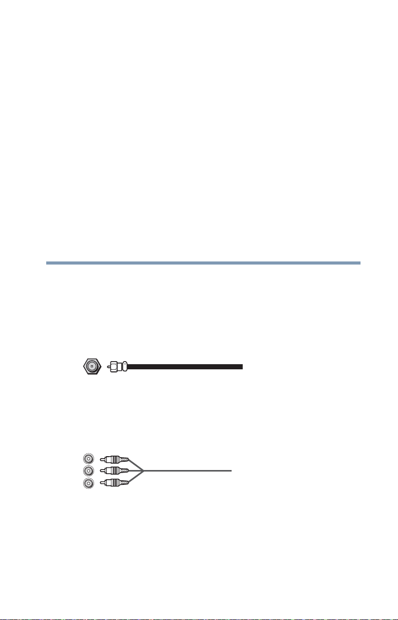
Coaxial cable (F-type)
(Sample Illustration) Coaxial cable
Coaxial (F-type) cable connects your antenna, cable TV service,
and/or cable converter box to the ANT/CABLE input on your TV.
Standard A/V cables (red/white/yellow)
(Sample Illustration) Standard AV cables
Standard A/V cables (composite video) usually come in sets of
three, and connects to video devices with analog audio and
composite video output. These cables (and the related inputs on
your TV) are typically color-coded according to use: yellow for
27
Page 28
28
NOTE
NOTE
Connecting Your TV
Overview of cable types
video, red for stereo right audio, and white for stereo left (or mono)
audio.
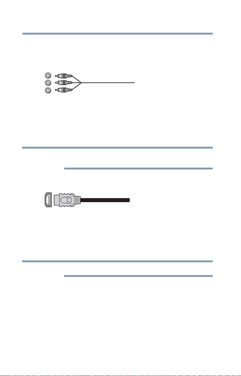
Component video cables (red/green/blue)
(Sample Illustration) Component video cables
Component video cables come in sets of three and are for use with
video devices with component video output. (ColorStream
Toshiba’s brand of component video.) These cables are typically
color-coded red, green, and blue. Separate audio cables are required
for a complete connection.
Component video cables provide better picture quality than
composite video cables.
HDMI® cable (with HDMI Logo)
(Sample Illustration) HDMI® cable
®
HDMI
devices that have an HDMI
digital audio and video in its native format. Separate audio cables
are not required, see “Connect a computer to the TV’s HDMI®
terminal” on page 41.
(High-Definition Multimedia Interface) cable connects to
HDMI® cables provide the best audio and picture quality.
®
®
output. An HDMI® cable delivers
is
Page 29
Dual-wand IR blaster cable
NOTE
Connect the dual-wand IR blaster cable to the IR blaster terminal to
control infrared remote controlled devices from the TV.
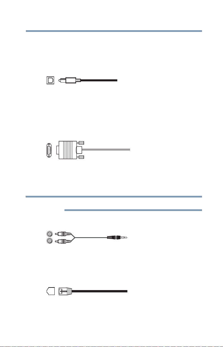
Optical audio cable
(Sample Illustration) Optical audio cable
Optical audio cable connects receivers with Dolby
(pulse-code modulation) optical audio input to the TV’s Digital
Audio Out terminal, see “Connecting a digital audio system” on
page 34.
Analog RGB (15-pin) computer cable
(Sample Illustration) Analog RGB (15-pin) computer cable
Analog RGB (15-pin) computer cable connects a computer to the to
the TV’s PC IN terminal, see “Connecting a computer to the TV’s
PC IN terminal:” on page 39.
Connecting Your TV
Overview of cable types
®
Digital or PCM
29
Separate audio cables are required.
3.5mm Stereo to RCA Y-cable
(Sample Illustration) 3.5mm Stereo to RCA Y- cable
3.5mm Stereo to RCA Y-cable connects an audio signal from DVI
device to TV.
LAN cable
(Sample Illustration) LAN cable
Standard LAN cable connects the TV to your home network, see
“Connecting the TV to a home network with an Internet connection
- wired” on page 43.
Page 30
30
HDMI 3HDMI 3
COLOR COLOR
STREAM STREAM
HD 1HD 1
VIDEO 2VIDEO 2
IN
OUT
CH 3
CH 4
VIDEO
OUT
AUDIO
OUT
COMPONENT VIDEO
L
R
Satellite
IN
P
B
P
R
Y
TV back panel
VHF/UHF
Antenna
Cable TV
Satellite receiver with component video
Satellite dish
Coaxial cable
Component
video cable
Standard audio
cable
AV Component adapter
cable (supplied)
Cable box
NOTE
Connecting an antenna, satellite receiver, and cable TV box
Crossover LAN cable connects the TV directly to a computer, see
“Connecting the TV directly to a computer without an Internet
connection” on page 42.
About the connection illustrations
Connecting Your TV
You can connect different types and brands of devices to your TV in
several different configurations. The connection illustrations in this
manual are representative of typical device connections only. The
input/output terminals on your devices may differ from those
illustrated herein. For details on connecting and using your specific
devices, refer to each device’s owner’s manual.
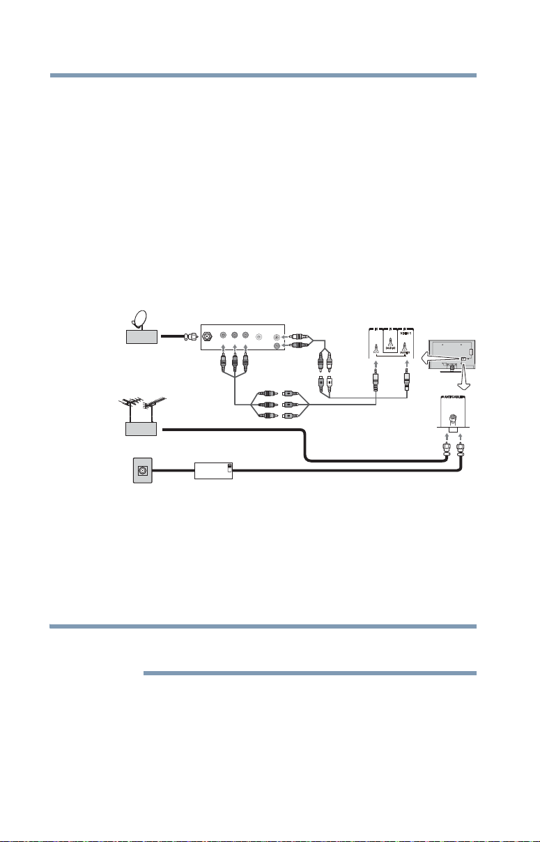
Connecting an antenna, satellite receiver, and cable TV box
(Sample Illustration) L6200U/L7200U Series—Connecting to an
antenna, satellite receiver, and cable TV box
Items needed:
❖ Coaxial cables
❖ Standard AV cables
❖ Component video cables (red/green/blue)
When you use a cable box, you may not be able to use the remote
control to program or access certain features on the TV.
To view the antenna or cable signal:
Select ANT/CABLE video input source on the TV.*
To view basic and premium cable channels:
Select the ANT/CABLE video input source on the TV.* Tune the
TV to channel 3 or 4 (whichever channel the cable box output is set
to). Use the cable box controls to change channels.
Page 31

Connecting Your TV
NOTE
VIDEO AUDIO
LR
COMPONENT VIDEO
P
B
P
R
Y
AUDIO
OUT
LR
R
W
Y
G
B
R
W
Y
R
W
R
B
R
W
Y
R
W
R
GB
G
W
TV back panel
A/V Component adapter
cable (supplied)
Standard
audio cable
Component
video cable
DVD player
Standard
A/V cable
Light green
Light
yellow
VCR
Yellow
White
Red
Green
Blue
AV adapter cable (supplied)
HDMI 4HDMI 4
HDMI 3HDMI 3
PC / COLOR STREAM HD 2PC / COLOR STREAM HD 2
COLOR COLOR
STREAM STREAM
HD 1HD 1
VIDEO 2VIDEO 2
Connecting DVD to ColorStream® or VCR to composite video
31
To view the VCR or camcorder video:
Turn On the VCR or camcorder video. Select VIDEO input source
on the TV.*
*To select the video input source, press the INPUT button on the
remote control, see “Selecting the video input to view” on page 86.
The unauthorized recording, use, distribution, or revision of
television programs, videotapes, DVDs, and other materials is
prohibited under the Copyright Laws of the United States and other
countries, and may subject you to civil and criminal liability.
Connecting DVD to ColorStream® or VCR to composite video
(Sample Illustration) L6200U/L7200U Series—Connecting a DVD
with ColorStream
®
or a VCR with composite video
Items needed:
❖ Coaxial cables
❖ Standard AV cables
❖ Standard audio cables
❖ Composite or component video cables
❖ You can connect the component video cables (plus audio
cables) from the DVD player or satellite receiver to the
COLOR STREAM HD terminal in the TV. The COLOR
STREAM HD terminal can be used to display Progressive
(480p, 720p) and Interlaced (480i, 1080i) scan systems.
Note that 1080p is not supported. Check the User’s Guide
of the DVD player in order to determine the best output
signal available.
Page 32

32
NOTE
NOTE
Connecting Your TV
Connecting remote IR devices
❖ If your DVD player or satellite receiver does not have
component video, connect a standard A/V cable to the
AUDIO/VIDEO terminal. If your DVD player has HDMI
video, see “Connecting an HDMI® or DVI device to the
HDMI® input” on page 35.
When you use ColorStream® HD or Video, please switch to the
appropriate AV mode.
To view antenna or Cable channels:
Select the ANT/CABLE video input source on the TV.*
To view the DVD player:
Turn ON the DVD player. Select the ColorStream
input source on the TV.*
To view satellite programs using the component video
connections:
Turn ON the satellite receiver. Select the ColorStream
input source on the TV.*
To view the VCR or view and record antenna channels:
Turn ON the VCR. Tune the VCR to the channel you want to
watch. Select the VIDEO video input source on the TV.*
To record a TV program while watching a DVD:
Turn ON the VCR. Tune the VCR to the channel to record. Select
the ColorStream
DVD.
*To select the video input source, press the INPUT button on the
remote control, see “Selecting the video input to view” on page 86.
®
HD video input source on the TV* to view the
®
HD video
®
®
HD video
The unauthorized recording, use, distribution, or revision of
television programs, videotapes, DVDs, and other materials is
prohibited under the Copyright Laws of the United States and other
countries, and may subject you to civil and criminal liability.
Connecting remote IR devices
Using the IR blaster OUT terminal
You can use the TV’s IR OUT terminal to remotely operate many
infrared remote-controlled devices enclosed in an entertainment
center or similar cabinet.
Items needed:
Page 33

Connecting Your TV
NOTE
Connecting remote IR devices
33
❖ Dual-wand IR blaster cable (see “Dual-wand IR blaster cable”
on page 29)
❖ Other cables as required to connect the device(s) to the TV (see
“Overview of cable types” on page 27)
See the remote IR blaster setup section.
To connect the IR blaster cable:
1 Locate the infrared sensor on the front of your device. This
sensor is marked on some devices.If you are having issues
locating the device's infrared sensor, see “If you cannot locate
the device’s infrared sensor:” on page 34.
2 Align one of the IR blaster cable’s wands approximately 1 inch
away from the infrared sensor on the front of the device and
attach it using double-sided mounting tape. If you have a
second device, attach the second wand in a similar manner.
If you do not have a second device, coil the second wand with a
rubber band and leave it behind the TV.
3 Plug the IR blaster cable’s plug into the TV’s IR Blaster Out
terminal.
Front of IR-controlled DVD player (for example)
Front of IR-controlled audio device (for example)
Infrared
sensor
Dual-
IR blaster cable wand
(approx.1 inch from device)
TV back panel
wand IR
blaster
cable
(Sample Illustration) L6200U/L7200U Series—Using the IR blaster
OUT terminal
Page 34

34
NOTE
Connecting Your TV
Connecting a digital audio system
To control the device(s):
Point the TV remote control toward the front of the TV and press
the button for the desired function. The signal passes from the
remote control through the TV to the device via the IR Blaster
cable. For more information, see “IR Blaster Setup” on page 55.
(Sample Illustration) Controlling the device(s) - remote control
The IR pass-through feature does not support all IR controlled
devices. Satisfactory quality may not be attainable with certain
devices.
If you cannot locate the device’s infrared sensor:
1 Turn off the device.
2 Starting at the device’s lower-left corner, place the end of the
device’s remote control (with the infrared emitter) so it touches
the front of the device. Press the POWER button.
(Do not use the TV’s remote control for this step.)
3 If the device turns on, the sensor is located where the remote
control touched the device.
4 If the device does not turn on, move the remote control slightly
to the right and press the POWER button again.
5 Repeat the previous steps if necessary.
Connecting a digital audio system
The TV’s Digital Audio Out terminal outputs a Dolby® Digital or
2-channel down-mixed PCM (pulse-code modulation) signal for
Page 35

Connecting Your TV
PLACE HOLDER
Optical audio
cable
TV back panel
Digital decoder or
digital audio system
NOTE
Connecting an HDMI® or DVI device to the HDMI® input
use with an external Dolby Digital decoder or other external audio
system with optical audio input.
You will need an Optical audio cable (Use an optical audio cable
that has the larger “TosLink” connector and not the smaller
“mini-optical” connector.)
35
(Sample Illustration) L6200U/L7200U Series—Connecting a
digital audio system
Before controlling the audio, see “Selecting the optical audio
output format” on page 126.
Some audio systems may not be compatible with Dolby Digital
bitstream signals. Older audio systems that are not compatible with
standard optical out signals may not work properly, creating a high
noise level that may damage speakers or headphones. THIS
DAMAGE IS NOT COVERED BY YOUR WARRANTY.
The DIGITAL AUDIO OUT terminal may not output some digital audio
sources because of copy restrictions.
The Dolby Digital format is available in the following situations:
❖ When tuned to a digital RF channel
❖ When an HDMI input is used
❖ When Media Player/Renderer products are used
Connecting an HDMI® or DVI device to the HDMI® input
The HDMI® input on your TV receives digital audio and
uncompressed digital video from an HDMI
®
source device, or
Page 36

36
NOTE
TV back panel
HDMI OUT
DVI/HDCP
OUT
AUDIO
R
L
OUT
HDMI device
DVI device
HDMI cable
Analog audio cable
HDMI-to-DVI adapter cable
HDMI 4HDMI 4
PC / COLOR STREAM HD 2PC / COLOR STREAM HD 2
Connecting Your TV
Connecting an HDMI® or DVI device to the HDMI® input
uncompressed digital video from a DVI (Digital Visual Interface)
source device.
This input is designed to accept HDCP (High- Bandwidth
Digital-Content Protection) program material in digital form from
EIA/CEA-861-D– compliant[1] consumer electronic devices (such
as a set-top box or DVD player with HDMI
The HDMI
®
input can accept and display VGA, SVGA, XGA,
WXGA, SXGA, 480i (60Hz), 480p (60Hz), 720p (60Hz), 1080i
(60Hz), and 1080p (24Hz/60Hz) signal formats. For detailed signal
specifications, see “HDMI® signal formats” on page 192.
The supported Audio formats are Linear PCM and Dolby
sampling rate 32/44.1/ 48 kHz.
To connect a PC to the HDMI® input, see “Connect a computer to the
TV’s HDMI® terminal” on page 41.
®
or DVI output).
®
Digital,
To connect an HDMI
(type A connector) per HDMI
❖ For proper operation, it is recommended that you use an
HDMI
®
cable with the HDMI® Logo ( ).
❖ To display an 1080ip/60Hz signal format, you will need a High
Speed HDMI
®
device, you will need one HDMI® cable
®
cable. A conventional HDMI®/DVI cable may
®
device:
not work properly.
❖ HDMI
®
cables transfer both video and audio. Separate analog
audio cables are not required (see illustration).
(Sample Illustration) L6200U/L7200U Series—Connecting an
®
HDMI
To view the HDMI
Select HDMI 1, HDMI 2, HDMI 3 or HDMI 4 video input source
or DVI device to the HDMI® Input
®
device video:
on the TV. (Press the INPUT button on the remote control. For
Page 37

Connecting Your TV
NOTE
NOTE
TV back panel
HDMI OUT HDMI
IN
HDMI OUT
HDMI OUT
Audio receiver
Playback device
Playback device
(HDMI®-CEC DVD player, etc.)
(HDMI®-CEC DVD player, etc.)
HDMI cable
HDMI cable
Using the TV remote and HDMI® CEC Control to control other
more information, see “Selecting the video input to view” on
page 86.
To connect a DVI device, you will need:
❖ HDMI
®
to DVI adapter cable
For proper operation, the length of an HDMI
®
to DVI adapter
cable should not exceed 9.8 ft (3m). The recommended length
is 6.6 ft (2m).
❖ 3.5mm Stereo to RCA Y-cable
An HDMI
®
to DVI adapter cable transfers video only. Separate
analog audio cables are required (see illustration).
To ensure that the HDMI® or DVI device is reset properly:
❖ When turning on your electronic components, turn on the TV
first, and then the HDMI
❖ When turning off your electronic components, turn off the
HDMI® or DVI device first, and then the TV.
[1] EIA/CEA-861-D compliance covers the transmission of
uncompressed digital video with high-bandwidth digital content
protection, which is being standardized for reception of highdefinition video signals. Because this is an evolving technology, it is
possible that some devices may not operate properly with the TV.
®
or DVI device.
37
Using the TV remote and HDMI® CEC Control to control other devices
To control the basic functions of connected audio/video devices
using the TV’s remote control, connect an HDMI
audio receiver or playback device. The HDMI
feature uses CEC technology as regulated by the HDMI
(Sample Illustration) L6200U/L7200U Series—Connecting an
®
HDMI
CEC compatible audio receiver and playback device
®
®
CEC Control
CEC compatible
®
standard.
Page 38

38
NOTE
NOTE
NOTE
Connecting Your TV
Connecting an HDMI® audio system
To connect an audio receiver and playback devices, you will need
®
HDMI
cables, see “HDMI® cable (with HDMI Logo)” on page 28.
If several devices are connected, HDMI® CEC Control feature may
not operate properly, see “HDMI
®
CEC Control input source
selection” on page 100.
For proper operation, it is recommended that you use HDMI
®
cables
with the HDMI® Logo ( ).
Before controlling the devices:
❖ For an explanation of setup and operations, see “Other HDMI
CEC Control functions” on page 101.
❖ Configure the connected devices. See each device’s operation
manual.
This feature is limited to models incorporating Toshiba’s
®
HDMI
CEC Control feature. However, Toshiba is not liable for those
operations. See the individual instruction manuals for compatibility
information.
When using an external AV amplifier the picture and sound may not
be properly synchronized. In this case, adjust the delay time of the
sound on the AV amplifier.
The control range of the delay time differs according to the device
you use.
®
Connecting an HDMI® audio system
If your HDMI® amplifier supports ARC, audio from the TV can be
sent to the amplifier via an existing HDMI
®
cable.
Page 39

Connecting a computer
TV back panel
HDMI
cable
AV amplier that
supports ARC
You will need and HDMI® cable.
Connecting Your TV
39
(Sample Illustration) L6200U/L7200U Series— Connecting to
®
HDMI
ARC
HDMI®'s ARC (Audio Return Channel) feature
This feature enables the audio signal of the TV to be sent to an AV
amplifier via the HDMI
cable from the audio output of the TV to the audio input of the AV
amplifier to reproduce the audio received from the tuner of the TV
through the AV amplifier.
Connecting a computer
With either the PC IN or HDMI® connection, you can view your
computer’s display on the TV and hear the sound from the TV’s
speakers.
®
cable. It will not be necessary to connect a
Page 40

40
PC/HDMI 3
(AUDIO)
HDMI® to DVI
adapter cable
PC audio
output
PC audio
cable
TV back panel
Computer
Conversion adapter
(if necessary)
Connecting a computer
Connecting a computer to the TV’s PC IN terminal:
When connecting a computer to the PC IN terminal on the TV, use
an analog RGB (15-pin) computer cable and a PC audio cable. For
more information, see “Overview of cable types” on page 27.
Connecting Your TV
(Sample Illustration) L6200U/L7200U Series—Connecting to a
computer through analog RGB cable
To use a computer, set the monitor output resolution on the
computer before connecting it to the TV. The supported signal
formats are VGA, SVGA, XGA, WXGA and SXGA. For detailed
signal specifications, see “Acceptable signal formats for PC IN,
HDMI®, and 3D” on page 191.
Other formats or non-standard signals will not be displayed
correctly.
To display the optimum picture, use the computer setting feature,
see “Using your computer with the TV” on page 102.
Page 41

Connecting Your TV
NOTE
Connecting a computer
41
❖ The PC audio input terminal on the TV is shared with the HDMI 4
and ColorStream
see “Setting the computer audio” on page 103.
❖ Some computer models cannot be connected to this TV.
❖ If the computer has a compatible mini D-sub15-pin terminal, an
adapter is not required.
❖ Depending on the content’s title and the computer’s
specifications, some scenes may be skipped or you may not be
able to pause during multi-angle scenes.
Signal names for mini D-sub 15-pin connector:
Pin No.: Signal Name: Pin No.: Signal Name: Pin No.: Signal Name:
1R 6Ground 11NC
2G 7Ground 12NC
3B 8Ground 13H-sync
4 NC* 9 NC 14 V-sync
5NC 10Ground 15NC
*NC=Not connected
®
HD2 terminal. For configuration information,
Connect a computer to the TV’s HDMI® terminal
When connecting a computer with a DVI port to the HDMI®
terminal on the TV, use an HDMI
audio cables.
When connecting a computer with an HDMI
cable (type A connector). Separate analog audio cables may not be
necessary, depending on computer hardware and setup.
®
to DVI adapter cable and analog
®
port, use an HDMI®
Page 42

42
(ARC)
ANALOG
AUDIO
NOTE
Connecting Your TV
Connecting to a home network
For more information, see “Overview of cable types” on page 27.
(Sample Illustration) L6200U/L7200U Series—Connecting to an
®
HDMI
terminal
The supported signal formats are VGA, SVGA, XGA, WXGA,
SXGA, 480i (60Hz), 480p (60Hz), 720p (60Hz), 1080i (60Hz), and
1080p (24Hz/60Hz). For signal specifications, see “Acceptable
signal formats for PC IN, HDMI®, and 3D” on page 191.
❖ The edges of the picture may be hidden.
❖ If receiving a 480i (HDMI), 480p (HDMI), 720p, 1080i, or 1080p
signal program, Native mode scales the video to display the
entire picture within the borders of the screen (i.e. no
overscanning).
Connecting to a home network
The LAN port allows your Toshiba TV to connect to your home
network.
You can use this home network to access photos, movies, and music
files that are stored on a Connected Media Server and play them on
your TV.
Page 43

Connecting Your TV
Computer
TV back panel
Computer
Router with a hub
TV back panel
Computer
Connecting to a home network
43
Connecting the TV directly to a computer without an Internet connection
You will need a Crossover LAN cable.
(Sample Illustration) L6200U/L7200U Series—Connecting a
computer without Internet connection
Connecting the TV to a home network without an Internet connection
Items needed:
❖ Standard LAN cables
❖ Router with a hub
(Sample Illustration) L6200U/L7200U Series—Connecting a
network without Internet connection
Page 44

44
Router with a hubModem (DSL or cable)
TV back panel
Cable or
phone jack
Computer
2, 3
2
1
2
Connecting Your TV
Connecting to a home network
Connecting the TV to a home network with an Internet connection wired
Items needed:
❖ Coaxial or telephone cable (depending on your modem type)
❖ Standard LAN cables
❖ Router with Hub
❖ Modem (DSL or cable)
(Sample Illustration) L6200U/L7200U Series—Connecting with
Internet connection - wired
Item: Description:
1 Coaxial or telephone cable (depending on your modem type)
2 Standard LAN cable
3 Do NOT connect a phone jack directly to the TV’s LAN port.
Connecting the TV to a home network with an Internet connection wireless
Items needed:
❖ Coaxial or telephone cable (depending on your modem type)
❖ Standard LAN cables
Page 45

Connecting Your TV
Wireless LAN access pointModem (DSL or cable)
Cable or
phone jack
Computer
2
1
2
Built-in WLAN system:
It is not necessary to connect an
external WLAN adapter to the TV
NOTE
Connecting to a home network
❖ Wireless LAN access point or wireless router
❖ Modem (DSL or cable)
45
(Sample Illustration) L6200U/L7200U Series—Connecting with
Internet connection - wireless
Item: Description:
1 Coaxial or telephone cable (depending on your modem type)
2 Standard LAN cable
The transmission speed over the wireless LAN and the distance
over which wireless LAN can reach may vary depending on
surrounding electromagnetic environment, obstacles, access point
design and configuration, and client design and software/hardware
configurations. The actual transmission speed will be lower than the
theoretical maximum speed.
The Built-in WLAN Adapter is based on the IEEE 802.11n
specification and may not be fully compatible with, or support
some features (e.g., security) of certain Wi-Fi equipment that
are based on the draft version of IEEE 802.11n.
Page 46

Chapter 3
Using the Remote Control
Controlling other devices
The TV’s remote control can operate other devices as described in
the IR Blaster section on page 55.
Installing batteries
To install batteries:
1 Pull up to open the cover.
46
(Sample Illustration) Removing the battery cover
2 Install two AA size batteries.
Page 47

Using the Remote Control
NOTE
NOTE
Installing batteries
Use carbon zinc batteries or alkaline batteries.
(Sample Illustration) installing the batteries
3 Slide on the cover.
Do not expose batteries to excessive heat such as sunshine, fire, etc.
❖ Every time you change the batteries, you must reprogram the
remote.
❖ Dispose of batteries in a designated disposal area.
❖ Always consider the environment when disposing of batteries.
Always follow applicable laws and regulations.
❖ If the remote does not operate correctly, or if the operating range
is reduced, replace the batteries.
❖ Always replace both batteries with new ones. Never mix battery
types or use new and used batteries together.
❖ Always remove batteries from the remote if they are dead or if the
remote control is not to be used for an extended period of time.
This prevents battery acid from leaking into the battery
compartment
47
Page 48

48
16.4 ft (5m)
42/47/55”
Using the Remote Control
Remote control effective range
Remote control effective range
1 For optimum performance, aim the remote control directly at
the TV and make sure there are no obstructions between the
remote control and the TV.
(Sample Illustration) Remote control effective range
Page 49

Using the Remote Control
29
30
28
27
25
23
22
20
17
16
15
12
9
8
57
6
3
4
2
1
26
24
21
19
18
14
13
11
10
31
32
33
34
35
36
37
38
39
40
NOTE
Learning about the remote control
Learning about the remote control
Only the buttons used to operate the TV are described in this
section.
For the HDMI
Control” on page 97.
®
CEC Control functions, see “Using HDMI® CEC
49
(Sample Illustration) Remote control overview
The L6200U series remote has no LIGHT button. The LIGHT button
is only available on the L7200U series remote.
Page 50

50
NOTE
1 POWER button Turns the TV On and Off.
When the TV is on, the power LED
indicator on the TV front glows green.
2 3D button Accesses the 3D options.
3 Light button Illuminates the keypad for five
(Model L7200U) seconds.
3 Sleep button
Accesses the sleep timer.
(Model L6200U)
4 TV button
5 Cable/Satellite
button
6 Auxillary button
7 BD/DVD button
8 Channel Number Directly tunes channels.
buttons (0-9)
9 (–) button Enters 2-part channel numbers.
10 INPUT button Selects the video input source.
11 CH RTN button Returns to the last viewed channel or
source.
12 VOL (+ / -) buttons Adjusts the volume level.
13 CH ( / ) buttons Cycles through programmed
channels.
14 MUTE button Reduces or turns off the sound.
15 INFO
button Displays TV status information as well
as program details, when available.
16 ePORTAL button Launches the ePortal page
on-screen.
17 NETFLIX button Launches the Netflix® application
on-screen.
18 SEARCH button Accesses the SearchAll function.
19 APPS button Launches the Apps window on-screen.
20 MENU button Accesses the main TV menu system.
21 GUIDE button Launches the MediaGuide
application on-screen.
22 ( / ) buttons Selects on-screen menu options.
23 (
/ / / ) Selects or adjusts programming
buttons menus when a menu is
on-screen.
24 OK button Selects the highlighted items on
the screen.
25 BACK button Returns to the previous screen.
26 EXIT button Closes on-screen menus.
27 REWIND button
28 PLAY button
29 FAST FOWARD
30 REC button Used for TV, Cable/Sat, BD/DVD,
Aux devices
31 STOP button Stops playback
32 SETUP button Used for TV, Cable/Sat, BD/DVD,
Aux devices
33 PAUSE button Pauses playback
34 QUICK
button Launches the Quick menu.
35 CC button Accesses the closed-caption
feature.
36 PIC SIZE button
Cycles through the picture sizes.
37 PIC MODE button Selects the picture mode.
38 eMANUAL button Launches the eMANUAL
application on-screen. Internet
connection required.
39 INTERNET button Launches the web browser
on-screen.
40 SLEEP button Accesses the sleep timer.
(Model L7200U)
Item: Description: Function: Item: Description: Function:
Switches to the TV input assigned to
each mode key: TV, CABLE/SAT,
BD/DVD, or AUX.
Short press rewinds/fast forwards.
Long press skips back/forward and
plays playback.
Using the Remote Control
Learning about the remote control
The error message “NOT AVAILABLE” may appear if you press a key
for a function that is not available.
Page 51

Chapter 4
NOTE
Initial Setup and Menu
Initial setup
When you first turn on or reset the TV, the Initial Setup window
appears.
❖ You can stop Initial Setup by pressing the EXIT button. However,
if you do not finish Initial Setup, the Initial Setup screen will
appear every time you turn on your TV. To finish Initial Setup,
see “Changing initial settings” on page 64.
❖ The EXIT button does not work until Menu Language/Country,
Time Zone/Daylight Saving Time, and Store/Home Mode have
been set.
51
Page 52

52
Language
EnglishMenu Language
Quick Setup
Country U.S.
Time zone
Time Zone
Daylight Saving Time
Central
On
Local Time Setting
To use the TV for displaying in a store showroom, please
select [Store]. [Home] mode is recommended for normal use.
Home
Store/Home Mode
Initial setup
Performing the initial setup
1 Menu Language/Country
Select a language and country. Press OK.
Initial Setup and Menu
(Sample Illustration) Selecting Menu Language/Country
2 Time Zone
Select a time zone.
(Sample Illustration) Selecting Time Zone
3 Daylight Saving Time
Select On or Off. Press OK.
Local Time Setting
Time Zone
Daylight Saving Time
Central
Off
(Sample Illustration) Selecting Daylight Saving Time
4 Store/Home Mode
Select Store or Home. Press OK.
(Sample Illustration) Selecting a location
Page 53

Initial Setup and Menu
Antenna
Cable
Next
ANT/CABLE In
NOTE
Start Scan
Auto Tuning
Previous settings will be lost! Press EXIT for no change.
NOTE
Initial setup
5 ANT/CABLE
To select Antenna, first select Antenna. Then select Next.
ANT/CABLE In
Antenna
Cable
Next
(Sample Illustration) Selecting Antenna
To select Cable, first select Cable. Then select Next.
53
(Sample Illustration) Selecting Cable
6 Start Scan
Select Start Scan. Press OK.
(Sample Illustration) Start Scan
If you do not want to scan channels, you do not need to make a
selection for ANT/CABLE. Select Next, and then press OK to skip
this step.
If you want to stop scanning, pressing the EXIT button while
scanning is in process.
Page 54

54
NOTE
Initial Setup and Menu
Initial setup
While scanning is in progress, the Auto Tuning Progress Screen
appears.
Auto Tuning (Antenna)
Progress
0%
Channel: 5
(Sample Illustration) Auto Tuning Progress Screen
After scanning is complete, the auto tuning results screen (such as
the one below) will appear.
Press OK or EXIT.
Auto Tuning (Antenna)
Antenna Channels Found: 12
Ch. Type RF Ch.
22
33
44
55
66
77
88
99
ATV
ATV
ATV
ATV
ATV
ATV
ATV
ATV
(Sample Illustration) Auto Tuning Results screen
Found
5
Although they may be displayed in the above list, encrypted
channels cannot be viewed.
If some channels are not found after scanning:
❖ Check the antenna/cable connections, and scan again.
❖ Connect the TV to the antenna or cable box directly and scan
again.
1 Press the MENU button. Select SETTINGS, SETUP,
Quick Setup, and then press OK.
A confirmation message appears.
2 Press the ( / arrow) buttons to select Ye s. Press OK.
3 Repeat setup to Step 6.
❖ If you selected Antenna previously, select Cable.
❖ If you selected Cable previously, select Antenna.
Page 55

4 Scan again.
NOTE
IR Blaster Setup
During the Initial Setup, the IR Blaster screen will appear with the
message, “IR Blaster setup will now begin. If you wish to skip,
please select Skip.”
To start the IR Blaster setup, select Next on the screen, or to skip
the setup, select Skip. If you wish to skip this setup, you can setup
the IR Blaster at any time through the PREFERENCES menu.
The IR Blaster may not work with some devices, and it may not
control certain features on your external devices.
1 The IR Blaster Setup screen will appear and you must choose
what devices to setup.
2 Select the Add button on the screen to add devices.
3 The IR Blaster Setup Add devices screen will appear. The
Device Type field will be highlighted.
4 Use the ( / arrow) buttons to select:
❖ Cable Box
❖ Satellite Box
❖ VCR
❖ Blu-ray, DVD Player
❖ Audio
❖ CD Player
❖ Video Accessory
The first column on the screen lists the subsequent fields
including: Brand, Select Device, Model Name, TV Input, etc.
5 Use the ( / arrow) buttons to select the options in the second
column that correspond to the IR device currently being setup.
Some fields will have screens with selectable lists of items,
while other fields may require using the keyboard to enter the
information.
6 To select the Code Set, use the ( / arrow) buttons to select
the codes set for the device.
Initial Setup and Menu
IR Blaster Setup
55
Page 56

56
NOTE
NOTE
NOTE
Initial Setup and Menu
IR Blaster Setup
If a model has more than one Code Set, a message will appear
stating “This model has more than one Code Set. Please select and
test your preferred Code Set.” You will need to choose a code set
using the ( / arrow) buttons and perform the Test option to
ensure the correct Code Set has been selected.
The Test option is available when the Device Type, Brand, Model
Name/Code Set have all been setup.
7 To select the TV Input to which the IR device is connected, use
the ( / arrow) buttons to select from the following options:
❖ (Only audio is selected as this device type)
❖ Video 1
❖ Video 2
❖ ColorStream HD 1
❖ Colorstream HD 2 (If selected)
❖ HDMI 1
❖ HDMI 2
❖ HDMI 3
❖ HDMI 4
❖ PC (if selected).
PC or ColorStream HD2 inputs depend on the shared PC input.
8 To set up the Guide Control, use the ( / arrow) buttons to
select:
❖ TV (this is the default)
❖ Device
9 To set up the Volume control, use the ( / arrow) buttons to
select:
❖ TV (this is the default)
❖ Amplifier
If the Amplifier option is selected, the Vol u m e Up / D o w n and
MUTE buttons will control the amplifier through the IR
blaster.
Page 57

Initial Setup and Menu
NOTE
NOTE
IR Blaster Setup
If Audio is selected as the device type, the volume option is active.
However if another device (other than Audio) is selected, then this
option is not available and grayed out.
10 After setting up all the options for the device, it is important to
test the IR Blaster’s control of the device by using the Test
option.
11 Once you have selected all the appropriate information on the
screen, use the ( / arrow) buttons to select the Done button.
To cancel this screen and return to the previous screen, select
the Cancel button.
To test the IR Blaster’s control of the device:
1 Use the ( / arrow) buttons to select the Tes t option from the
IR Blaster Setup screen.
The TV will then send the power on and power off command to
the device through the IR Blaster with approximately a 5
second interval.
2 A message screen will appear asking you “Was your device
powered on and off by the IR Blaster? If not, please check your
device and IR blaster position.” If the test failed, a “Test
Failed” message will appear on the screen.
To set up the timing control for your device:
1 Use the ( / arrow) buttons to select Timing Control. A
screen will appear allowing you to set up the Interval Time for
the device.
57
The Timing Control is activated when the Guide Control is set for the
TV.
2 Use the ( / arrow) buttons to select from the following
options:
❖ 0.125 sec
❖ 0.25 sec (this is the default)
❖ 0.375 sec
❖ 0.5 sec
❖ 0.625
❖ 0.75
❖ 0.875
Page 58

58
NOTE
Initial Setup and Menu
Network Setup
❖ 1 sec
3 Select the Tes t button.
A message screen will appear asking you “Was your device
changed from one channel to another by the IR blaster? If not,
please check your configuration.” If the test failed, a “Test
Failed” message will appear on the screen.
4 Once you have selected all the appropriate information on the
screen, use the ( / arrow) buttons to select the Done button.
To cancel this screen and return to the previous screen, select
the Cancel button.
❖ When the Done button is selected, if the TV input has already
been selected for another device an Alert Screen will appear.
❖ When the Done button is selected, if the HDMI input has already
been selected for another HDMI
will appear.
❖ When the Done button is selected, if the Device Type selected is
the Cable Box, Satellite Box or Blu-ray ™ DVD Player, the
following message will be displayed: “Are you sure you want to
apply this device to MediaGuide?” You must select the Yes or
No option using the ( / arrow) buttons. After this selection,
the IR Blaster Setup main screen will appear.
❖ The HDMI
function when HDMI and HDMI
the IR Blaster is already setup, the IR Blaster function should be
stopped when the same HDMI port is being used with at least
one HDMI® CEC device.
®
CEC control function has priority over the IR Blaster
®
CEC device an Alert Screen
®
CEC devices are connected. If
Network Setup
During the Initial Setup, the Network Setup screen will appear with
the message, “Network Setup will now begin. If you wish to skip,
please select Skip.” To start the Network Setup, select Next on the
screen or to skip the setup, select Skip. If you wish to skip this
setup, you can setup the Network at any time through the
NETWORK menu.
In order to setup your network, you must first select the type of
network you wish to set up:
Page 59

Initial Setup and Menu
NOTE
NOTE
MediaGuide Setup
1 Use the ( / arrow) buttons to select Wired or Wireless
network.
If you select Wired, proceed to the Network Connection Test
(Step 3). If you selected Wireless network, please proceed to
the following step.
2 Using the ( / arrow) buttons, select the type of Wireless
setup option: Easy Setup (WPS), Assisted Setup, or Manual
Setup.
❖ Easy Setup (WPS). If your Access Point (AP) supports WPS, this
method can be used. WPS is a standard designed to simplify the
connection of wireless LAN equipment and the setup of network
security features.
❖ Assisted Setup (setup using the AP's notification information).
The Network Name, Authentication, and Encryption are decided
based on information from the AP. You need to manually set the
Security Key for this method.
❖ Manual Setup (to input all settings manually).
3 Once your wired or wireless network has been configured,
perform a Network Connection Test.
A network connection test screen will appear while the test is
being performed. If the test was successful, the successful
connection screen will appear.
If the network connection test failed, the connection failure
screen will appear.
For more information, see“Setting up the Network” on
page 131 .
4 Press the OK button on the screen to return to the Initial Setup
menu.
59
In order to secure your home network, it is strongly recommended
that you use a wireless access point with encryption.
MediaGuide Setup
During the Initial Setup, the MediaGuide screen will appear with
the message, “MediaGuide setup will now begin. If you wish to
skip, please select Skip.” To start the MediaGuide Setup, select
Next on the screen, or to skip the setup, select Skip. If you wish to
Page 60

60
NOTE
NOTE
Initial Setup and Menu
MediaGuide Setup
skip this setup, you can setup the MediaGuide at any time through
the setting menu of the MediaGuide application.
To setup your MediaGuide:
When you select Next (as described above) the Connect to the
Network screen will appear.
1 Make sure the TV is connected to the network, and then select
the Ye s or No button using the ( / arrow) buttons. Then
press the OK button.
The TV will now establish connection with the information
services it uses. A confirmation screen will appear if the
connection was established.
2 Press the OK button on the confirmation screen.
If the TV is unable to connect to these services from the
network, an error message appears.
If the error message appears, you should check your network
connections and try again.
For more information, see “Setting up the Network” on page 131.
The Online Account Setup will appear. Please follow the on-screen
instructions to register the guide.
If you wish to select any other service subscription such as Netflix®,
you may complete this on the website as well.
After completion of the network connection check, a new screen
will appear describing the terms and conditions.
3 Use the arrow buttons to select the I Agree button on the
screen.
The Zip/Postal Code screen will appear.
4 Use the number buttons to enter your zip code. Press the
Continue button.
The Choose Provider screen will appear.
5 Use the ( / arrow) buttons to select your service provider
from the list.
After completion of all of these steps, the MediaGuide will start up.
Page 61

Support Information
NOTE
NETWORK
SETTINGS
GET HELP
TIMERS
3D
PICTURE
SOUND PREFERENCES
SETUP
❖ When the “Support Information” screen appears, press the OK
button.
Refer to this information if there is a problem and you need to contact
Customer Support. To find help, the following operation can be
performed at any time. MENU button > Menu > GET HELP >
System Information > OK button.
Navigating the menu system
❖ To open the menu system, press the MENU button on the
remote control or TV control panel.
Initial Setup and Menu
Navigating the menu system
61
(Sample Illustration) Main menu
❖ When a menu is open, press the ( / / / arrow) buttons on
the remote control to move in the corresponding direction.
❖ To select a highlighted item or save your menu settings, press
the OK button. (A highlighted menu item appears in a different
color in the menu.)
❖ All menus close automatically if no selection is made within
approximately 60 seconds.
❖ To close a menu instantly, press the EXIT button.
Page 62

62
Initial Setup and Menu
Main menu layout
Main menu layout
To open the main menus in the table below, press the MENU button
on the remote control or TV control panel.
1st Layer 2nd Layer 3rd Layer Page
GET HELP Software Licenses page 141
Software Upgrade page 140
System Information page 107
eMANUAL page 142
3D 3D Auto Start page 81
2D to 3D Depth page 84
3D PIN page 81
3D Safety Settings page 83
3D Important Information page 72
SETTINGS SOUND SOUND Menu page 125
PICTURE PICTURE Menu page 115
PREFERENCES PREFERENCES Menu page 64
SETUP SETUP Menu page 64
NETWORK Media Player Setup page 157
Network Setup page 131
Network Device Setup page 136
Smart Apps Setup page 142
TIMERS On Timer page 104
Sleep Timer page 105
Game Timer page 96
Page 63

Initial Setup and Menu
NOTE
Quick Menu
Quick Menu
Quick menu helps you access some options more quickly.
Press the QUICK button to display the Quick menu and press the
( / )buttons to select an option.
Quick menu items differ depending on the current mode.
Quick Menu Item Page
Picture Mode page 79
3D Settings page 78
®
CEC Player Control page 99
HDMI
Speakers page 165
Wireless Information page 135
Interval Time page 165
Repeat page 161
Device Information page 159
SOUND page 165
PICTURE page 79
63
Page 64

Chapter 5
Setting up your TV
How to navigate the menu
❖ Press the MENU button. Select SETTINGS, Main menu,
Submenu, and then press the OK or EXIT button.
Format: Description:
MENU Press the MENU button.
SETTINGS Press the ( / arrow) buttons to select SETTINGS.
Press the ( / arrow) buttons to select a menu icon (SOUND,
Main menu
Submenu Press the ( / arrow) buttons to select a menu.
OK Press the OK button.
Changing initial settings
From Quick Setup:
1 Press the MENU button.
2 Select SETTINGS, SETUP, Quick Setup, and then press the
PICTURE, PREFERENCES, SETUP, GET HELP, 3D, SETTINGS,
NETWORK, TIMERS)
OK button.
A confirmation message appears.
64
Page 65

3 Press the ( / arrow) buttons to select Ye s.
4 Press the OK button.
To change settings, see “Initial setup” on page 51.
Individual settings
Menu Language
You can choose from three different menu language settings
(English, Français, and Español). The TV displays menus and
messages in your preferred language. You can also select the
country in which you reside.
1 Press the MENU button.
2 Select SETTINGS, SETUP, and then Menu Language.
3 Press the ( / arrow) buttons to select your preferred
language.
4 Press the ( arrow) button to select Country.
5 Press the ( / arrow) buttons to select the country.
Local Time
This setting allows you to specify the correct time zone for your
region.
1 Press the MENU button.
2 Select SETTINGS, SETUP, TV Settings, and then press the
OK button.
3 Press the ( / arrow) buttons to select Local Time.
4 Press the OK button.
5 Select an option:
❖ Time Zone
❖ Daylight Saving Time
6 Press the ( / arrow) buttons to select your time zone or
select On to activate Daylight Saving Time.
Setting up your TV
How to navigate the menu
65
Store/Home Mode
You can select Store or Home to designate the TV location. Select
Home for normal home use.
1 Press the MENU button.
2 Select SETTINGS, SETUP, and then Store/Home Mode.
Page 66

66
NOTE
NOTE
Setting up your TV
How to navigate the menu
3 Press the ( / arrow) buttons to select Home.
4 Press the OK button.
ANT/CABLE In
This setting configures the antenna input source for the
ANT/CABLE terminal.
1 Press the MENU button.
2 Select SETTINGS, SETUP, and then ANT/CABLE In.
3 Select Antenna or Cable and press Next.
4 Select Cable and press Next.
If you do not want to scan channels, you do not need to make a
selection for ANT/CABLE. Select Next and press OK to skip this
step.
5 Select Start Scan.
After scanning is complete, the auto tuning results screen will
appear.
6 Press OK or EXIT.
Storing channels in memory (optional)
To make sure your TV stops only on the channels you want when
you press the CH Up/Down arrow buttons on the remote control or
the control panel, store those channels in the TV’s memory.
Auto Tuning
You must set up the antenna/cable input source first. See “Initial
setup” on page 51.
You can set up the TV to detect all active channels in your area and
store them in its memory. Then you can manually store or skip
individual channels from memory.
Option: Description:
Note: If you select Cable, auto tuning deletes previously stored
Cable
channels from memory.
This setup requires some time, but you do not need to repeat the
setup unless your cable TV service’s lineup changes significantly.
Page 67

Option: Description:
NOTE
Auto tuning retains stored channels and stores newly found
Antenna
1 Press the MENU button.
2 Select SETTINGS, SETUP, Auto Tuning, and then press the
3 Press the OK button to start Auto Tuning or press the EXIT
4 To view the programmed channels, press the CH Up/Down
channels into memory.
To skip an antenna source channel and remove it from memory, set
the channel to be skipped. See “Skipping channels” on page 68.
To tune to channels not stored in memory, use buttons 0–9 and the
DASH button on the remote control.
OK button.
A confirmation screen appears.
button to abort.
The TV cycles through the channels and stores all active
channels in memory.
arrow buttons.
Setting up your TV
How to navigate the menu
67
Manual Tuning
After storing channels in memory, you can manually enter channels
if the channel number is known.
1 Press the MENU button.
2 Select SETTINGS, SETUP, Manual Tuning, and then press
the OK button.
3 Use buttons 0–9 on the remote control to enter the channel
number (for example, 56).
4 Press the OK button.
5 Press the OK button again to begin Manual Tuning.
The channels found are listed at the bottom of the screen.
Option: Description:
ATV Analog channel
DTV Digital channel
Page 68

68
NOTE
Setting up your TV
How to navigate the menu
Skipping channels
To prevent a channel from being viewed, you can set it to be
skipped.
1 Press the MENU button.
2 Select SETTINGS, SETUP, TV Settings, and then press the
OK button.
3 Press the ( / arrow) buttons to select Channel Options, and
then press the OK button.
The list of channels appears.
(Sample Image) Channel options
4 Move to the Skip column ( ) and press the (/ arrow)
buttons to select a channel to skip.
5 Press the OK button.
The box is selected.
6 To clear the selection, press the OK button.
You cannot tune skipped channels using the CH Up/Down arrow
buttons. Use buttons 0–9 and the DASH button on the remote
control.
Skipping video inputs
You can set video inputs to be skipped when selecting inputs in the
Input selection window.
To turn on skip
1 Press the MENU button.
Page 69

2 Select SETTINGS, PREFERENCES, AV Connection, and
then press the OK button.
3 Press the ( / arrow) buttons to select Input Labeling.
4 Press the OK button.
5 Press the ( / arrow) buttons to select the item you wish to
skip. Then press the RED button to turn on Skip.
To turn off skip
Press the RED button again to turn off Skip.
Labeling analog TV channels
1 Press the MENU button.
2 Select SETTINGS, SETUP, TV Settings, and then press the
OK button.
3 Press the ( / arrow) buttons to select Channel Options, and
then press the OK button.
The list of channels appears.
Setting up your TV
How to navigate the menu
69
(Sample Image) Channel options
4 Press the ( / arrow) buttons to select a channel to label.
5 Press the OK button.
The Software Keyboard window appears.
6 Input a name using the Software Keyboard, see “Using the
software keyboard” on page 139.
7 Press the BLUE button.
Page 70

70
Setting up your TV
How to navigate the menu
Labeling video inputs
The input labels are shown in the input selector and banner
displays. You can label video inputs according to the devices you
have connected to the TV.
1 Press the MENU button.
2 Select SETTINGS, PREFERENCES, AV Connection, and
then press the OK button.
3 Press the ( / arrow) buttons to select Input Labeling, and
then press the OK button.
4 Press the ( / arrow) buttons to select the item you wish to
label. Press the ( / arrow) buttons to select Receiver,
Cable, DVD, Game, PC, Recorder, Satellite, VCR or Bluray™.
5 Repeat Step 4 for other video inputs.
Configuring shared inputs
To set Shared AV Audio
1 Press the MENU button.
2 Select SETTINGS, PREFERENCES, AV Connection, and
then press the OK button.
3 Press the ( / arrow) buttons to select Video 1/ColorStream
HD1 Audio/HDMI 3 Audio.
4 Press the ( / arrow) buttons to select ColorStream HD1,
Video 1, or HDMI 3.
To set Shared PC Audio
1 Press the MENU button.
2 Select SETTINGS, PREFERENCES, AV Connection, and
then press the OK button.
3 Press the ( / arrow) buttons to select PC/HDMI 4 Audio.
4 Press the ( / arrow) buttons to select PC or HDMI 4.
Setting the Auto Input feature
You can change TV inputs using the MODE SELECT buttons on
the remote control: TV, CABLE/SAT, BD/ DVD, or AUX. After
setting an input for a specific MODE SELECT button, the TV
automatically switches to the input.
Page 71

Auto Input settings options for each MODE SELECT button:
NOTE
Option: Description:
TV ANT/CABLE
CABLE/SAT
BD/DVD
AUX
ANT/CABLE, Video 1 Video 2 ColorStream HD1, HDMI 1, HDMI 2,
HDMI 3, HDMI 4, PC
Video 1 Video 2 ColorStream HD1, HDMI 1, HDMI 2, HDMI 3,
HDMI 4, PC
ANT/CABLE, Video 1 Video 2 ColorStream HD1, HDMI 1, HDMI 2,
HDMI 3, HDMI 4, PC
The TV mode select button will be restricted to the ANT/CABLE
input.
To set Auto Input
1 Press the MENU button.
2 Select SETTINGS, PREFERENCES, Mode Select Key
Setup, and then press the OK button.
The Mode Select window will appear.
3 Press the ( / arrow) buttons to set the Enable Mode Select
Key to On.
4 Press the ( / arrow) buttons to select the mode you wish to
set.
5 Press the ( / arrow) buttons to select an input source for that
mode.
6 Repeat the procedure for other modes.
Setting up your TV
How to navigate the menu
71
To turn off Auto Input
❖ Select Off in Step 3.
To reset Auto Input
❖ Select Reset, and then press the OK button.
Page 72

Chapter 6
NOTE
Basic Features
Viewing 3D images
Before using the 3D function, note the following:
In addition to compatible 3D glasses, viewing 3D programming
requires the following (not included):
❖ Compatible 3D playback device or 3D source.
❖ 3D capable HDMI
If you wish to obtain extra 3D glasses:
Toshiba provides 3D glasses for this television as an option.
To obtain them visit:
US: http://ceaccessories.toshiba.com/
Canada: http://www.shoptoshiba.ca/
®
cable.
Use the type of 3D glasses that are compatible with to your TV.
72
Page 73

Basic features
Viewing 3D images
Health precautions:
❖ Due to the possible impact on vision development, viewers of 3D
programming should be age 6 or above. Children may be more
susceptible to health effects from viewing 3D images and should
be closely supervised.
❖ Some viewers may experience a seizure or blackout when
exposed to certain flashing images or lights contained in certain
3D television pictures or video games. Anyone who has had a
seizure, loss of awareness, or other symptom linked to an
epileptic condition, or has a family history of epilepsy, should
contact a health care provider before using the 3D function of
this product.
Handling the 3D glasses:
❖ When cleaning the 3D glasses, gently wipe with a dry, soft cloth.
First, remove any dirt or dust from the 3D Glasses.
Harsh rubbing or use of a dirty or coarse cloth will scratch the
3D Glasses. Do not use benzene, paint thinner, alcohol, water, or
abrasive cleaners, which may damage the 3D glasses.
❖ When not using the 3D glasses, store them away from high
temperatures and humidity.
❖ Do not store the 3D glasses in areas of extreme heat or cold, as
deformation can occur. If deformation occurs, replace the 3D
glasses.
❖ The lenses of the 3D glasses are different from those of ordinary
glasses, and are very thin. Be very careful in handling the 3D
glasses as the lens can pop out easily.
❖ Do not put excessive force on the lenses.
❖ Do not scratch the surface of the lenses with sharp objects.
❖ Do not drop or bend the 3D glasses.
❖ Do not use benzene, paint thinner, alcohol, water, or abrasive
cleaners, which may damage the 3D glasses.
❖ The 3D glasses are not subject to repair. If the glasses are broken
or scratched, purchase a new pair of 3D glasses.
❖ The 3D glasses are not subject to repair, but can be replaced if a
problem occurs due to an initial fault with the glasses
73
Page 74

74
NOTE
NOTE
Basic features
Using 3D functions
Watching the TV:
❖ Proper 3D effects or 3D-to-2D conversion results may not be
obtained depending on the received 3D content.
❖ 3D effect and image quality may vary depending upon content
quality and display device capability/ functionality/settings.
❖ Wear the 3D glasses properly, otherwise you may not see the
correct 3D images.
❖ When not viewing 3D images, take off the 3D glasses; otherwise,
it may be difficult to see the display on other products such as
your computer, digital clock, or calculator, etc.
❖ Use the 3D glasses at the proper viewing angle and distance, see
“Safety Precautions for 3D glasses” on page 6.
Use a high-speed HDMI® cable when you connect a device such as a
3D compatible Blu-ray Disc™ player or computer to the TV. When
you use a standard HDMI
correctly.
Some functions cannot be shown in 3D mode.
®
cable, 3D images may not display
Using 3D functions
Incoming video signals can either be in 2D or 3D format. A 2D
signal can be viewed in either 2D or 3D, and 3D can be viewed in
either 2D or 3D. If the TV can detect the fact that a signal is 3D, it
can change to 3D mode automatically, see “Setting the 3D start
message” on page 82. Otherwise you can change the viewing mode
using the 3D button. Finally, the format of the 3D signal can be
either Side by Side (SBS) or Top and Bottom (TAB). You may have
to choose the correct format if the TV can not detect it
automatically, see “Selecting 3D format from the Quick menu in
3D mode” on page 78.
You can also change 2D images to 3D images by pressing the 3D
button when viewing in 2D.
Page 75

Basic features
NOTE
Using 3D functions
❖ In order to switch to 3D, the TV must be receiving a 3D signal.
❖ If appropriate mode and format are not selected, 3D image is not
correctly displayed.
❖ If the appropriate 3D mode and format are not selected, the 3D
image will not display correctly.
❖ There are individual differences in perception of 3D images.
❖ When viewing 3D images, wear the 3D glasses.
❖ The 2D to 3D conversion function is activated and controlled by
you according to your personal preferences.
❖ The 2D to 3D conversion function is meant for enjoyment of 2D
home video, and other 2D content you create, in 3D according to
your personal preferences.
❖ It is not intended for unauthorized use of copyrighted works. To
the extent that you need to obtain permission from a copyright
holder to view copyrighted works, it is your responsibility to
obtain such permission.
❖ The 2D to 3D conversion function is not intended for use with
pre-recorded 2D copyrighted content owned by a third-party
unless the copyright owner has given direct or indirect
permission, or unless applicable law permits such use. To the
extent you need to obtain permission from a copyright holder to
view copyrighted works, it is your responsibility to obtain such
permission.
75
Page 76

76
Basic features
Using 3D functions
Switching display mode or selecting 3D format
There are four TV viewing modes:
Mode: Description:
3D Displays 3D images.
2D Displays 2D images by changing 3D images to 2D.
2D to 3D Displays 3D images by changing 2D images to 3D.
Native Displays a received signal format as it is.
3D signals can be sent in one of three formats:
3D Format: Description:
Side by Side (SBS Images for the left and right eyes are positioned
side-by-side.
To and Bottom (TAB) Images for the left and right eyes are positioned at the
top and bottom of the screen
Frame Packing (FP)* Images for the left and right eyes are positioned at the
* This format cannot be selected manually.
❖ If the right and left images are the same in Native mode, select
SBS.
❖ If the top and bottom images are the same in Native mode,
select TAB.
top and bottom of the screen.
The 3D button operation
Depending on the input mode, the 3D button function may be
different when viewing Native mode.
Input: Function:
Analog Inputs Changes the viewing mode to 2D to 3D mode.
®
HDMI
Analog Broadcast Changes the viewing mode to 2D to 3D mode.
Digital Broadcast Displays the selection window.
Displays the selection window.
Page 77

Input: Function:
NOTE
Basic features
Using 3D functions
77
HDMI with 3D Auto
Detect Information
Internet Service Displays the selection window.
When viewing 3D mode or 2D to 3D mode, pressing the 3D button
changes the viewing mode to Native mode.
The 3D mode may not be available with certain features.
Changes the viewing mode to 3D mode
Switching to 3D mode
1 Set 3D Auto Start to 3D.
2 Press the 3D button and select 3D while viewing 2D mode or
Native mode.
Input Signal/Switching Display Mode Trigger Press 3D Button
Type Additional
Information
With 3D Auto Detect
Information
3D Format
Signal
Format Source
Signal
FP
SBS
TAB
Select 3D Select 2D to
3D
Without 3D Auto
Detect Information
2D Format Signal
* Correct 3D image.
SBS
TAB
Page 78

78
Basic features
Using 3D functions
Selecting 3D format from the Quick menu in 3D mode
1 Press the QUICK button. Select 3D Settings, and then press
the OK button.
2 Press the ( / arrow) buttons to select 3D Format Select, and
then press the OK button.
3 Press the ( / arrow) buttons to select Side by Side or Top
and Bottom.
Input Signal/Switching Display Mode Trigger Quick menu/
3D Format Select
Type Additional
Information
With 3D Auto Detect
Information
3D Format
Signal
Without 3D Auto
Detect Information
2D Format Signal
* Correct 3D image.
Format Source
Signal
FP
SBS
TAB
SBS
TAB
SBS TAB
Page 79

Basic features
Using 3D functions
Switching to 2D mode
1 Set 3D Auto Start to 2D.
2 Press the 3D button while viewing 3D mode.
Input Signal/Switching Display Mode Trigger Press 3D Button
79
Type Additional
Information
With 3D Auto Detect
Information
3D Format
Signal
Without 3D Auto
Detect Information
2D Format Signal
* Correct 2D image.
Format Source
Signal
FP
SBS
TAB
SBS
TAB
Select 3D Select 2D to
Selecting 2D format from the Quick menu in 2D mode
1 Press the QUICK button. Select 3D Settings, and then press
the OK button.
2 Press the ( / arrow) buttons to select 2D Format Select, and
then press the OK button.
3 Press the ( / arrow) buttons to select Side by Side or Top
and Bottom.
3D
Page 80

80
NOTE
NOTE
Input Signal/Switching Display Mode Trigger Quick menu/
Basic features
Using 3D functions
3D Format Select
Type Additional
3D
Format
Signal
2D Format Signal
* Correct 2D image.
Information
With 3D Auto
Detect
Information
Without 3D
Auto Detect
Information
Format Source
FP
SBS
TAB
SBS
TAB
Take off the 3D glasses in 2D mode
Switching to Native mode
Press the 3D button while viewing 3D mode.
Press the 3D button while viewing 2D to 3D mode.
Signal
SBS TAB Native
When 3D format signal with 3D Auto Detect Information is received,
it is not possible to switch to Native.
Quick menu in 2D mode
1 Press the QUICK button. Select 3D Settings, and then press
the OK button.
2 Press the ( / arrow) buttons to select 2D Format Select,
then press the OK button.
3 Press the ( / arrow) buttons to select Native.
Page 81

To switch 2D to 3D mode
NOTE
❖ Press the 3D button and select 2D to 3D while viewing 2D or
Native mode.
When using ATV, Video, ColorStream HD, Internet, or PC, the
viewing mode can be changed to 2D to 3D mode by pressing 3D.
Setting the auto start mode
This controls what the TV does when it detects a 3D format signal
with 3D Auto Detect Information.
1 Press the MENU button.
2 Use the ( / arrow) buttons to select 3D, and then press the
OK button.
3 Press the ( / arrow) buttons to select 3D Auto Start.
4 Press the ( / arrow) buttons to select 3D, 2D, or Off.
Option: Description:
Basic features
Setting the 3D PIN code
81
3D Displays in 3D mode automatically when 3D format signal with 3D Auto
Detect Information is received.
2D Displays in 2D mode automatically when 3D format signal with 3D Auto
Detect Information is received.
Off Displays a screen that allows you to select 3D or 2D when 3D format signal
with 3D Auto Detect Information is received.
Setting the 3D PIN code
A 3D PIN code is necessary for using 3D Safety Settings.
Enter a new PIN code
1 Press the MENU button.
2 Use the ( / arrow) buttons to select 3D, and then press the
OK button.
3 Press the ( / arrow) buttons to select 3D PIN, and then press
the OK button.
4 Press the number buttons to enter a 4-digit number, and then
confirm the code.
Page 82

82
NOTE
NOTE
Basic features
Setting the 3D PIN code
the PIN code cannot be set to “0000.”
Change or delete your PIN code
1 Press the MENU button.
2 Use the ( / arrow) buttons to select 3D, and then press the
OK button.
3 Press the ( / arrow) buttons to select 3D PIN.
4 Press the number buttons to enter your 4-digit PIN code.
5 Select Change PIN or Delete PIN, and then press the OK
button.
❖ The PIN code cannot be set to “0000.”
❖ If PIN is deleted, 3D Safety Settings are grayed out, and the
settings are reset to the factory default.
Forgotten PIN codes
1 Press the MENU button.
2 Use the ( / arrow) buttons to select 3D, and then press the
OK button.
3 Press the ( / arrow) buttons to select 3D PIN.
4 Press the INFO button 4 times within 5 seconds.
The code clears.
5 Enter a new PIN code.
Setting the 3D start message
When this feature is set to On, a message displays on the screen
when a 3D signal is received.
1 Press the MENU button.
2 Use the ( / arrow) buttons to select 3D, and then press the
OK button.
3 Press the ( / arrow) buttons to select 3D Safety Settings,
and then press the OK button.
4 Enter your 4-digit 3D PIN code.
5 Press the ( / arrow) buttons to select 3D Start Message.
Page 83

6 Press the ( / arrow) buttons to select On or Off.
NOTE
Setting the 3D Lock
When this feature is set to On, you must enter your 3D PIN code to
change the display mode to 3D mode or 2D to 3D mode.
1 Press the MENU button.
2 Use the ( / arrow) buttons to select 3D, and then press the
OK button.
3 Press the ( / arrow) buttons to select 3D Safety Settings,
and then press the OK button.
4 Enter your 4-digit 3D PIN code.
5 Press the ( / arrow) buttons to select 3D Lock.
6 Press the ( / arrow) buttons to select On.
Setting the 3D Timer Lock
When the 3D Timer Lock feature is set to On, the PIN input
window and the 3D start message will not appear while the 3D
Enable timer is active, even if you switch to 3D Mode. This
prevents it from asking for the 3D Lock PIN, and will not display
the 3D start message every you switch to 3D.
1 Press the MENU button.
2 Use the ( / arrow) buttons to select 3D, and then press the
OK button.
3 Press the ( / arrow) buttons to select 3D Safety Settings,
and then press the OK button.
4 Enter your 4-digit 3D PIN code.
5 Press the ( / arrow) buttons to select 3D Timer Lock.
6 Press the ( / arrow) buttons to select On.
Basic features
Setting the 3D PIN code
83
The PIN input window appears when “continue” is selected in the
reminder dialogue box for Enable 3D Timer even if 3D Timer Lock is
activated.
Setting the Enable 3D Timer
This feature allows you to set a reminder to not watch a 3D video
for an extended period of time. Once a set period of time has
passed, a dialogue box appear asking if you wish to continue
viewing.
Page 84

84
Basic features
Setting the 3D PIN code
1 Press the MENU button.
2 Use the ( / arrow) buttons to select 3D, and then press the
OK button.
3 Press the ( / arrow) buttons to select 3D Safety Settings,
and then press the OK button.
4 Enter your 4-digit 3D PIN code.
5 Press the ( / arrow) buttons to select Enable 3D Timer.
6 Press the ( / arrow) buttons to select 30, 60, 90, or 120
minutes.
7 To cancel the timer, select Off.
Displaying 3D Important Information
1 Press the MENU button.
2 Use the ( / arrow) buttons to select 3D, and then press the
OK button.
3 Press the ( / arrow) buttons to select 3D Important Info,
and then press the OK button.
Adjusting 2D to 3D depth
With this feature, you can adjust the level of 3D depth.
Within the Menu:
1 Press the MENU button.
2 Use the ( / arrow) buttons to select 3D, and then press the
OK button.
3 Press the ( / arrow) buttons to select 2D to 3D Depth.
4 Press the ( / arrow) buttons to select either 1, 2, 3, 4, or 5,
and then press the OK button.
Within the Quick menu:
1 Press the QUICK button in 2D to 3D mode.
2 Press the ( / arrow) buttons to select 3D Settings, and then
press the OK button.
3 Press the ( / arrow) buttons to select 2D to 3D Depth.
4 Press the ( / arrow) buttons to select either 1, 2, 3, 4, or 5,
and then press the OK button.
Page 85

Basic features
Tuning Channels
85
Switching left and right images
The left and right images of the glasses can be swapped. If 3D
images look blurry, switch the left and right sides of the 3D image.
1 Press the QUICK button to open the Quick menu.
2 Press the ( / arrow) buttons to select 3D Settings, and then
press the OK button.
3 Press the ( / arrow) buttons to select Left and Right
Image. Press the ( / arrow) buttons to select Swapped.
Tuning Channels
Tuning to the next programmed channel
Press the CH Up/Down arrow buttons on the remote control or TV
control panel.
Tuning to a specific channel (programmed or unprogrammed)
Channel: Description:
Analog Use the 0–9 buttons on the remote control. (For example, to select channel
125, press 1, 2, 5.), and then press the OK button.
Digital Use the 0–9 buttons on the remote control to enter the major channel
number. Press the DASH button, (For example, to select digital channel
125- 1, press 1, 2, 5, –, 1.), and then press the OK button.
Using Channel Return
You can switch between two channels without entering a channel
number each time. This feature also works for external inputs.
1 Select the first channel you want to view.
2 Select a second channel using the Channel Number buttons
(and press the DASH button if needed).
3 Each time you press the CH RTN button, the TV switches
between the last two channels that were tuned.
Using SurfLock™
The SurfLock™ feature temporarily programs one channel to the
CH RTN button so that you can quickly return to it from any other
channel. This feature also works for external inputs.
Page 86

86
Basic features
Selecting the video input to view
To temporarily program the CH RTN button with a particular
channel:
1 Tune to the channel you wish to program to the CH RTN
button.
2 Press and hold the CH RTN button
seconds until the message “Memorized” appears. The channel
has been programmed to the CH RTN button.
3 You can then change channels repeatedly, and when you press
the CH RTN button, the memorized channel is tuned to.
After pressing the CH RTN button
again, the memory is cleared and the button functions as Channel
Return.
Selecting the video input to view
To select the video input to view:
1 Press the INPUT button on the remote control or TV control
panel.
2 Change the input:
❖ Press
❖ Repeatedly press the ( / arrow) buttons, and then press
❖ Repeatedly press the INPUT button.
0–8.
the OK button.
for approximately 4
and then changing channels
Inputs
0 ANT/CABLE
1Video 1
2Video 2
3 ColorStream HD1
4HDMI 1
5HDM 2
6HDM 3
7HDM 4
8PC
Page 87

Basic features
NOTE
NOTE
Using closed captions
❖ You can label the video input sources according to the specific
devices you have connected to the TV, see “Labeling video
inputs” on page 70.
❖ You can skip sources, see “Skipping video inputs” on page 68.
❖ Inputs that are set to be skipped will be skipped when selecting
by repeatedly pressing the INPUT button or the ( / arrow)
buttons.
❖ You can select inputs that are set to be skipped using the
number buttons.
❖ If one or more HDMI
input, the icon appears in the input selector. In this case, the
label, see “Labeling video inputs” on page 70 will not appear in
the input selector.
®
To select an HDMI
CEC device:
1 Press the ( / arrow) buttons to select an HDMI
2 Press the ( arrow) button. The list of HDMI
for that input appears.
3 If the input has multiple HDMI
arrow) buttons to select a device.
4 Press the OK button.
®
CEC devices are connected to an HDMI®
®
CEC devices
®
CEC devices, use the ( /
®
input.
87
Using closed captions
To turn on the closed caption mode:
1 Press the MENU button. Select SETTINGS, SETUP, TV
Settings, and then press the OK button.
2 Press the ( / arrow) buttons to select Closed Captions, and
then press the OK button.
3 Press the ( / arrow) buttons to select Closed Captions
Display.
4 Press the ( / arrow) buttons to select On or Off.
If Closed Captions Display is set to Off, Analog CC Mode and Digital
CC Settings will be not available.
Analog CC mode
The closed caption mode has two options:
Page 88

88
NOTE
Mode: Description:
Captions Displays the dialogue, narration, and sound effects of TV programs and
Text Displays information not related to the current program, such as weather or
Basic features
Using closed captions
videos that are closed captioned (usually marked “CC” in program guides).
stock data (when provided by individual stations).
To view captions or text:
1 Press the MENU button. Select SETTINGS, SETUP, TV
Settings, and then press the OK button.
2 Press the ( / arrow) buttons to select Closed Captions, and
then press the OK button.
3 Press the ( / arrow) buttons to select Analog CC Mode.
To view captions:
Press the ( / arrow) buttons to highlight CC1, CC2, CC3,
or CC4.
(Sample Illustration) Captions
If the program or video you have selected is not closed captioned, no
captions will be displayed.
Page 89

Basic features
NOTE
NOTE
NOTE
Using closed captions
To view text:
Press the ( / arrow) buttons to highlight T1, T2, T3, or T4.
(Sample Illustration) Captions - text
If text is not available in your area, a black rectangle may appear on
the screen. You can remove this rectangle by setting Closed
Captions Display to Off.
A closed caption signal may not be displayed when a videotape
is dubbed, signal reception is weak, or signal reception is
non-standard.
89
Digital CC settings
You can customize the closed caption display characteristics.
❖ These settings are available for digital channels only.
❖ You cannot set Caption Text and Background as the same color.
Mode: Description
Caption size Auto, Small, Standard, Large
Caption text type Auto, Mono (with Serif), Prop. (with Serif), Mono (without Serif),
Prop. (without Serif), Casual, Cursive, Small Capitals
Caption text edge Auto, None, Raised, Depressed, Uniform, Left Drop Shadow,
Right Drop Shadow
Caption text color Auto, Black, White, Red, Green, Blue, Yellow, Magenta, Cyan
Text foreground opacity Auto, Transparent, Translucent, Flashing, Solid
Background color Auto, Black, White, Red, Green, Blue, Yellow, Magenta, Cyan
Page 90

90
NOTE
Mode: Description
Text background opacity Auto, Transparent, Translucent, Flashing, Solid
Caption text edge color Auto, Black, White, Red, Green, Blue, Yellow, Magenta, Cyan
Basic features
Using closed captions
To customize the closed captions:
1 Press the MENU button. Select SETTINGS, SETUP, TV
Settings, and then press the OK button.
2 Press the ( / arrow) buttons to select Closed Captions, and
then press the OK button.
3 Press the ( / arrow) buttons to select Digital CC Settings.
and then press the OK button.
4 Press the ( / arrow) buttons to select a characteristic. Press
the ( / arrow) buttons to select the format for that
characteristic.
Using the Closed Caption button
If you press the CC button when an analog channel is tuned or from
an external input (480i signal from the video input):
❖ The CC bar will appear and will display the options, CC1-4,
T1-4.
If you press the CC button when a digital channel is tuned:
❖ The CC bar will appear and will display the available caption
options for that channel or service.
Setting the PIN code
A PIN code is necessary for some menus.
The Parental Control and Locks menu is grayed out if no PIN has
been set.
Page 91

Entering a new PIN code
NOTE
NOTE
1 Press the MENU button. Select SETTINGS,
PREFERENCES, Parental PIN, and then press the OK
button.
2 Use the number buttons to enter a 4-digit number, and then
confirm the code.
The PIN code cannot be set to “0000”.
Changing or deleting your PIN code
1 Press the MENU button. Select SETTINGS,
PREFERENCES, Parental PIN, and then press the OK
button.
2 Use the number buttons to enter your 4-digit PIN code.
3 Select Change PIN or Delete PIN, and then press the OK
button.
❖ The PIN code cannot be set to “0000”.
❖ If you delete the PIN code, the settings of Parental Controls and
Locks are reset.
Basic features
Using parental controls
91
Forgotten PIN code
1 Press the MENU button. Select SETTINGS,
PREFERENCES, Parental PIN, and then press the OK
button.
2 Press the INFO button 4 times within 5 seconds. The code is
cleared.
3 Enter a new PIN code.
Using parental controls
Blocking TV programs and movies by rating (V-Chip)
Some TV programs and movies include signals that classify the
content of the program (as unsuitable for younger viewers). The
V-Chip feature in this TV detects the signals and blocks the
programs according to the ratings you select.
Page 92

92
NOTE
NOTE
NOTE
Basic features
Using parental controls
The V-Chip feature in this TV supports the U.S. V-Chip system only.
1 Press the MENU button. Select SETTINGS,
PREFERENCES, Parental Control and Locks, and then
press the OK button.
2 Enter your 4-digit PIN code.
3 Press the ( / arrow) buttons to highlight Enable Rating
Blocking.
4 Press the ( / arrow) buttons to select On.
5 Press the ( / arrow) buttons to select Edit Rating Limits,
and then press the OK button.
The Edit Rating Limits screen appears.
6 Press the ( / / / arrow) buttons.
7 Press the OK button to select a level of blocking.
A box with an “X” indicates a rating that will be blocked. As
you highlight a rating, the rating’s definition appears at the
bottom of the screen.
This feature will not be available if no PIN code is set.
Downloading an additional rating system
An additional rating system may be available for use in selectively
blocking TV programs and movies.
The currently tuned station must be receiving a digital signal before
an additional rating system can be downloaded.
1 Press the MENU button. Select SETTINGS,
PREFERENCES, Parental Control and Locks, and then
press the OK button.
2 Enter your 4-digit PIN code. The Parental Control and Locks
screen appears.
3 Press the ( / arrow) buttons to highlight Enable Rating
Blocking.
4 Press the ( / arrow) buttons to select On.
Page 93

Basic features
NOTE
NOTE
Using parental controls
5 Press the ( / arrow) buttons to select Edit Rating Limits,
and then press the OK button.
The Edit Rating Limits screen appears.
6 Select Alt RS, and then press the OK button.
The Edit Alternate Ratings screen appears.
❖ The Alt RS button is only available if an additional rating system
is currently available.
❖ The download may take several minutes.
❖ The information displayed on the Alternate Ratings screen
depends on the configuration of the additional rating system
available at the time of download.
7 Press the ( / / / arrow) buttons.
8 Press the OK button to select the desired level of blocking. A
box with an “X” indicates the rating that will be blocked.
❖ You can only download the additional rating system once. You
cannot download updates if they become available.
❖ The additional rating system is not designed, transmitted, or
controlled by the TV or Toshiba, nor is the availability of an
additional rating system determined or controlled by Toshiba.
Similarly, the rating of programs in an additional rating system is
not determined, transmitted, or controlled by the TV or Toshiba.
❖ The additional rating system is an evolving technology;
therefore, availability, content, and format may vary.
93
Rating system
Independent rating system for broadcasters:
Ratings: Description and Content themes:
TV-MA Mature Audience Only (This program is specifically designed to be viewed
by adults and therefore may be unsuitable for children under 17. L) Crude or
indecent language S) Explicit sexual activity V) Graphic violence
TV-14 Parents Strongly Cautioned (This program contains some material that
many parents would find unsuitable for children under 14 years of age.)
D) Intensely suggestive dialogue L) Strong, coarse language S) Intense
sexual situations V) Intense violence
Page 94

94
NOTE
Ratings: Description and Content themes:
Basic features
Using parental controls
TV-PG Parental Guidance Suggested (This program contains material parents may
TV-G General Audience (Most parents would find this program suitable for all
TV-Y7,
TV-Y7FV
TV-Y
Ratings: Description and Content themes:
X X-rated (For adults only)
NC-17 Not intended for anyone 17 and under
R Restricted (Under 17 requires accompanying parent or adult)
PG-13 Parents Strongly Cautioned (Some material may be inappropriate for
PG Parents Strongly Cautioned (Some material may be inappropriate for
find unsuitable for younger children.) D) Some suggestive dialogue
L) Infrequent coarse language S) Some sexual situations V) Moderate
violence
ages.)
Directed to Older Children (This program is designed for children age 7 and
above.
NOTE: Programs in which fantasy violence may be more intense or more
combative than other programs in this category are designated TV-Y7FV.)
All Children (This program is designed to be appropriate for all children.)
Independent rating system for movies
children under 13)
children under 13)
G
Display: Description:
NONE The program is rated None.
(No rating appears) No rating information is provided.
General Audience (Appropriate for all ages)
Indication other than rating system
If you place an “X” in the box next to “Rated “None””, programs rated
“None” or “Not Rated” will be blocked; Programs that do not provide
any rating information will not be blocked.
Page 95

Displaying ratings
NOTE
To display the rating of the program you are watching, press the
INFO button on the remote control.
Unlocking programs
If you try to tune to a program that exceeds the rating limits you
have set, the TV will enter program lock mode and a warning
message will appear on screen. Follow the instructions to
temporarily unlock the program.
Locking specific channels
A channel that is configured as Locked cannot be viewed unless the
PIN code is entered first, see “Setting the PIN code” on page 90.
1 Press the MENU button. Select SETTINGS, SETUP, TV
Settings, and then press the OK button.
2 Press the ( / arrow) buttons to select Channel Options, and
then press the OK button.
The list of channels appears.
Basic features
Locking specific channels
95
(Sample Illustration) Channel options
3 Press the ( arrow) button and then the ( / arrow) buttons
to select a channel in the lock column, and then press the OK
button.
4 You must enter your PIN code to lock channels.
If no PIN code has been set, a warning appears. See, “Setting the PIN
code” on page 90.
5 The box is selected. To clear the selection, press the OK
button.
Page 96

96
Basic features
Locking specific channels
Locking video inputs
You can lock video inputs and channels 3 and 4. You cannot view
the input sources or channels until you unlock the inputs by
entering the PIN code.
1 Press the MENU button. Select SETTINGS,
PREFERENCES, Parental Control and Locks, and then
press the OK button.
2 Enter your 4-digit PIN code.
3 Press the ( / arrow) buttons to highlight Input Lock.
4 Press the ( / arrow) buttons to select Video, Video+, or Off.
Mode: Description:
Video Locks Video 1, Video 2, ColorStream HD1, HDMI 1, HDMI 2, HDMI 3,
HDMI 4, and PC.
Video+ Locks Video 1, Video 2, ColorStream HD1, HDMI 1, HDMI 2, HDMI 3,
HDMI 4, PC, and channels 3 and 4.
Select Video+ if you want to play video tapes via the ANT/CABLE input.
Off Unlocks all video inputs and channels 3 and 4.
Setting a time limit for games
You can use the GameTimer® to set a time limit for playing a video
game. When the time expires, the TV locks all external inputs.
1 Press the MENU button. Select TIMERS, GameTimer, and
then press the OK button.
2 Enter your 4-digit PIN code.
3 Press the ( / arrow) buttons to select 30, 60, 90, or 120
minutes.
4 To cancel the timer, select Off.
To deactivate the Input Lock once the GameTimer
❖ Set the Input Lock to Off, see “Locking video inputs” on
page 96.
®
has activated it:
Page 97

❖ A message appears when 10 minutes, 3 minutes, and 1 minute
NOTE
NOTE
are remaining.
❖ If the TV loses power with time remaining, the TV will enter Input
Lock mode when power is restored (as if the GameTimer had
been activated). You must deactivate the Input Lock, see
“Locking video inputs” on page 96.
Locking the control panel
You can lock the control panel to prevent your settings from being
changed accidentally (by children, for example). When Panel Lock
is set to On, none of the controls on the control panel operate
except POWER.
1 Press the MENU button. Select SETTINGS,
PREFERENCES, Parental Control and Locks, and then
press the OK button.
2 Enter your 4-digit PIN code.
3 Press the ( / arrow) buttons to select Panel Lock.
4 Press the ( / arrow) buttons to select On.
Basic features
Using HDMI® CEC Control
97
When Panel Lock is set to On, “Panel Lock” appears on screen when
the buttons on the TV control panel are pressed. If the POWER button
is pressed, the TV turns off and you must use the remote control to
turn it on.
To unlock the control panel:
❖ Select Off in Step 4 above.
Using HDMI® CEC Control
This feature uses CEC technology and allows you to control
Toshiba HDMI
control via HDMI
When Enable HDMI
Setup menu is set to On, the following HDMI
functions are enabled.
®
CEC compatible devices from the TV remote
®
connection.
®
CEC Control in the HDMI® CEC Control
®
CEC Control
Page 98

98
NOTE
NOTE
Basic features
Using HDMI® CEC Control
To set HDMI® CEC Control Setup
1 Press the MENU button. Select SETTINGS,
PREFERENCES, HDMI
press the OK button.
2 Press the ( / arrow) buttons to highlight Enable
HDMI CEC Control.
3 Press the ( / arrow) buttons to select On.
If you set Enable HDMI® CEC Control to Off, the other items under
HDMI® CEC Control Setup will be grayed out.
4 Press the ( / arrow) buttons to select an item. Press the
( / arrow) buttons to select On or the desired mode:
❖ TV Auto Power: On/Off
❖ Auto Standby: On/Off
❖ Amplifier Control: On/Off
❖ Speaker Preference: TV Speakers/Amplifier
These functions depend on the connected devices.
®
CEC Control Setup, and then
Controlling HDMI® CEC playback devices
With your TV’s remote control, you can control the connected
®
HDMI
Button: Description:
CEC playback device (DVD player, etc.) you are watching.
Begins playback
Stops playback
Pauses the picture during play or record mode
A short press fast-forwards, and a long press skips forward.
A short press rewinds, and a long press skips backward.
Fast forward
Rewind/reverse
Page 99

Button: Description:
NOTE
Menu navigation, etc.
Enters content with a menu
Basic features
Using HDMI® CEC Control
99
RED, GREEN,
YELLOW,
BLUE
0–9 buttons
Channel
Up/Down
Controls various operation
Changes to the next available channel up or down in the sequence
These functions depend on the connected devices.
HDMI® CEC Player Control menu functions
1 Press the QUICK button to open the Quick menu.
2 Select HDMI
button.
3 Press the ( / arrow) buttons to select the item you want to
control, and then press the OK button.
Item: Description:
Power
Root Menu
Content Menu
Turns the selected device On and Off
Accesses the selected device’s top menu
Accesses the content list when the OK button is pressed
®
CEC Player Control, and then press the OK
Setup Menu
Accesses the device’s setup menu
Page 100

100
NOTE
NOTE
NOTE
Using HDMI® CEC Control
These functions depend on the connected devices.
Basic features
The HDMI
®
CEC Player Control item is not available under the
following conditions:
❖ A non-HDMI
❖ The Enable HDMI
❖ The connected HDMI
®
input is selected
®
CEC Control item is set to Off
®
CEC device is not a playback or
recording device
HDMI® CEC Control input source selection
If an HDMI® CEC device with HDMI® switching capability
(e.g. an amplifier) is connected to the HDMI
another HDMI
®
CEC device that is connected to the master HDMI®
device.
Use the INPUT button on the remote control or the control panel,
see “Learning about the remote control” on page 49.
Adjusting the amplifier’s audio
Using the TV’s remote control, you can adjust or mute the sound
volume of your amplifier.
❖ The VOL (+ -) buttons adjust the volume level.
❖ The MUTE button turns off the sound.
1 Press the MENU button. Select SETTINGS,
PREFERENCES, HDMI
press the OK button.
2 Press the ( / arrow) buttons to highlight Speaker
Preference.
3 Press the ( / arrow) buttons to select Amplifier.
®
CEC Control Setup, and then
®
input, you can select
Confirm that a connected HDMI® CEC device (such as DVD player,
etc.) is selected for the Amplifier input source.
❖ You can also use this function when the amplifier is connected to
the TV’s DIGITAL AUDIO OUT terminal (not HDMI
®
connection).
Select a digital audio input mode on the amplifier.
❖ These functions depend on the device connected.
 Loading...