

FILE NO. 050-200623GR
(MFR’S VERSION A)
SERVICE MANUAL
42" DIGITAL PLASMA
COLOR TELEVISION
42HP86
The above model is classified as a green product (*1), as indicated by the underlined serial number.
This Service Manual describes replacement parts for the green product. When repairing this green
product, use the part(s) described in this manual and lead-free solder (*2).
For (*1) and (*2), see the next page.
DOCUMENT CREATED IN JAPAN, July, 2006 GREEN

(*1) GREEN PRODUCT PROCUREMENT
The EC is actively promoting the WEEE & RoHS Directives that define standards for recycling
and reuse of Waste Electrical and Electronic Equipment and for the Restriction of the use of
certain Hazardous Substances. From July 1, 2006, the RoHS Directive will prohibit any
marketing of new products containing the restricted substances.
Increasing attention is given to issues related to the global environmental. Toshiba Corporation
recognizes environmental protection as a key management tasks, and is doing its utmost to
enhance and improve the quality and scope of its environmental activities. In line with this,
Toshiba proactively promotes Green Procurement, and seeks to purchase and use products,
parts and materials that have low environmental impacts.
Green procurement of parts is not only confined to manufacture. The same green parts used in
manufacture must also be used as replacement parts.
(*2) LEAD-FREE SOLDER
This product is manufactured using lead-free solder as a part of a movement within the consumer
products industry at large to be environmentally responsible. Lead-free solder must be used in
the servicing and repair of this product.
WARNING
This product is manufactured using lead free solder .
DO NOT USE LEAD BASED SOLDER TO REPAIR THIS PRODUCT !
The melting temperature of lead-free solder is higher than that of leaded solder by 86°F to 104°F
(30°C to 40°C). Use of a soldering iron designed for lead-based solders to repair product made
with lead-free solder may result in damage to the component and or PCB being soldered. Great
care should be made to ensure high-quality soldering when servicing this product especially
when soldering large components, through-hole pins, and on PCBs as the level of heat
required to melt lead-free solder is high.
A1-1

SERVICING NOTICES ON CHECKING
1. KEEP THE NOTICES
As for the places which need special attentions,
they are indicated with the labels or seals on the
cabinet, chassis and parts. Make sure to keep the
indications and notices in the operation manual.
2. AVOID AN ELECTRIC SHOCK
There is a high voltage part inside. Avoid an
electric shock while the electric current is
flowing.
3. USE THE DESIGNATED PARTS
The parts in this equipment have the specific
characters of incombustibility and withstand
voltage for safety. Therefore, the part which is
replaced should be used the part which has
the same character.
Especially as to the important parts for safety
which is indicated in the circuit diagram or the
table of parts as a mark, the designated
parts must be used.
11.
When you remove the cover, do not scratch the
FPC on both ends of PDP Module.
12.
Hold the four ends holder and be careful not to
touch the glass area.
13.
Take care for the damage of vacuum exhaust
pipe due to a collision.
14.
Moisture condensation may damage the PDP
Module.
So, leave it for 48 hours at the service room.
5. PUT PARTS AND WIRES IN THE
ORIGINAL POSITION AFTER
ASSEMBLING OR WIRING
There are parts which use the insulation
material such as a tube or tape for safety, or
which are assembled in the condition that
these do not contact with the printed board.
The inside wiring is designed not to get closer
to the pyrogenic parts and high voltage parts.
Therefore, put these parts in the original
positions.
4. BE CAREFUL WITH THE PDP PANEL
1.
When you handle the PDP Filter you must
wear the gloves twice, because, you are to
avoid soil it by your sweat and dust.
2.
When you lift the PDP Filter you should hold it
with the palm of your hand.
Don’t pick up it with your fingers.
3.
The back side of PDP Filter tends to damaged.
Since there is no coating.
Therefore, it put into the packing box at the
time of delivery, without piling up even at the
time of unused.
Also, when you take out it from a packing box,
be careful of the rubbing.
4.
When the surface becomes dirty, wipe it with a
soft cloth as you draw a circle.
When it is dirty hardly, wipe it with a cloth
ethanol infiltrated.
Don’t use ethanol for the back side.
5.
Do not apply it to direct sunshine so that the
characteristic may change.
6.
When you inspect the surface (the scratch, the
dirt and the air bubble), use the fluorescent
light.
7.
When you use SCREW DRIVER and SCREW,
be careful of a metallic powder being mixed.
8.
Do not damage the PDP Module with a
DRIVER.
9.
Do Handling with the PDP Module by 2
persons.
10.
There is a step difference between the cover
and PDP Module.
So, when you remove the screws, place a
cushion on it so that the PDP Module is not
being scratched.
Then remove the screws carefully.
PERFORM A SAFETY CHECK AFTER
6.
SERVICING
Confirm that the screws, parts and wiring which
were removed in order to service are put in the
original positions, or whether there are the
portions which are deteriorated around the
serviced places serviced or not. Check the
insulation between the antenna terminal or
external metal and the AC cord plug blades.
And be sure the safety of that.
(INSULATION CHECK PROCEDURE)
Unplug the plug from the AC outlet.
1.
Remove the antenna terminal on TV and turn
2.
on the TV.
Insulation resistance between the cord plug
3.
terminals and the eternal exposure metal
[Note 2] should be more than 2.5M ohm by
using the 500V insulation resistance meter
[Note 1].
If the insulation resistance is less than 2.5M
4.
ohm, the inspection repair should be
required.
[Note 1]
If you have not the 500V insulation
resistance meter, use a Tester.
[Note 2]
External exposure metal: Antenna terminal
Screw
21pin jack
Side RCA jack
Rear RCA jack
Headphone jack
A1-2

HOW TO ORDER PARTS
Please include the following informations when you order parts. (Particularly the VERSION LETTER.)
1. MODEL NUMBER and VERSION LETTER
The MODEL NUMBER can be found on the back of each product and the VERSION LETTER can be
found at the end of the SERIAL NUMBER.
2. PART NO. and DESCRIPTION
You can find it in your SERVICE MANUAL.
IMPORTANT
When you exchange IC and Transistor with a heat sink, apply silicon grease (YG6260M) on the contact
section of the heat sink. Before applying new silicon grease, remove all the old silicon grease.
(Old grease may cause damage to the IC and Transistor).
PANEL LOCK
To unlock the Panel Lock, please follow the steps below.
Turn Unit ON.
1.
Press and hold the ‘VOLUME DOWN’ key on the front panel for more than 10 seconds.
2.
The Panel Lock has now been cleared.
3.
A1-3

TABLE OF CONTENTS
GREEN PRODUCT PROCUREMENT ........................................................................................
LEAD-FREE SOLDER ................................................................................................................
SERVICING NOTICES ON CHECKING.....................................................................................
HOW TO ORDER PARTS ..........................................................................................................
IMPORTANT ...............................................................................................................................
PANEL LOCK..............................................................................................................................
TABLE OF CONTENTS..............................................................................................................
GENERAL SPECIFICATIONS ...................................................................................................
DISASSEMBLY INSTRUCTIONS
1.EXCHANGE METHOD OF PDP MODULE...........................................................................
2. REMOVAL AND INSTALLATION OF FLAT PACKAGE IC..................................................
SERVICE MODE LIST ................................................................................................................
WHEN REPLACING EEPROM (MEMORY) IC ..........................................................................
FUNCTION OF PCB ....................................................................................................................
ELECTRICAL ADJUSTMENTS..................................................................................................
TROUBLESHOOTING GUIDE ...................................................................................................
BLOCK DIAGRAM
SCALER/LVDS/MICON/ADC/VIDEO ENHANCER/REGULATOR ........................................
AV SWITCH/AV SWITCH2/AV JACK/STEREO/SOUND AMP/JACK....................................
TUNER/POWER ......................................................................................................................
INTERFACE.............................................................................................................................
MICON2 ...................................................................................................................................
PRINTED CIRCUIT BOARDS
AV/REMOCON ........................................................................................................................
SCALER...................................................................................................................................
DIGITAL ...................................................................................................................................
SIDE JACK/OPERATION/FILTER ..........................................................................................
SCHEMATIC DIAGRAMS
AV SWITCH2 ...........................................................................................................................
SWITCH/AMP ..........................................................................................................................
AV JACK ..................................................................................................................................
STEREO ..................................................................................................................................
SOUND AMP/HEADPHONE AMP ..........................................................................................
POWER ...................................................................................................................................
AV JACK2 ................................................................................................................................
TUNER.....................................................................................................................................
MICON .....................................................................................................................................
SCALER...................................................................................................................................
ADC..........................................................................................................................................
VIDEO ENHANCER ................................................................................................................
LVDS........................................................................................................................................
JACK ........................................................................................................................................
AV SWITCH .............................................................................................................................
REGULATOR...........................................................................................................................
INTERFACE_HDMI IC ............................................................................................................
HDMI MICON2.........................................................................................................................
OPERATION/SIDE JACK/FILTER ..........................................................................................
WAVEFORMS .............................................................................................................................
MECHANICAL EXPLODED VIEWS...........................................................................................
MECHANICAL REPLACEMENT PARTS LIST .........................................................................
ELECTRICAL REPLACEMENT PARTS LIST...........................................................................
A1-1
A1-1
A1-2
A1-3
A1-3
A1-3
A2-1
A3-1~A3-5
B1-1~B1-8
B2-1, B2-2
C-1
C-2
C-3
D-1~D-5
E-1~E-6
F-1, F-2
F-3, F-4
F-5, F-6
F-7, F-8
F-9, F-10
G-1~G-4
G-5~G-8
G-9, G-10
G-11, G-12
H-1, H-2
H-3, H-4
H-5, H-6
H-7, H-8
H-9, H-10
H-11, H-12
H-13, H-14
H-15, H-16
H-17, H-18
H-19, H-20
H-21, H-22
H-23, H-24
H-25, H-26
H-27, H-28
H-29, H-30
H-31, H-32
H-33, H-34
H-35, H-36
H-37, H-38
I-1~I-3
J-1~J-3
K1-1, K1-2
K2-1~K2-6
A2-1
GENERAL SPECIFICATIONS
G-1 TV PDP PDP Size / Visual Size 42.32 inch / 1074.9 mmV
System Number of Pixels(H x V) 1024(H) x 768(V)
G-2 Tuning Broadcasting System Analog
System Digital --
G-3 Signal Video Signal Input Level 1 V p-p/75 ohm
G-4 Power Power Source AC 120V AC 60Hz
G-5 Regulation Safety CSA
G-6 Temperature Operation +/- 0oC ~ +40oC
G-7 Operating Humidity Less than 80% RH
G-8 Clock and Clock
Timer Sleep Timer Max Time 120 Min
Color System NTSC
Speaker 4 Speaker
Main Size 2.2 x 5.0 inch
Tweeter Size 2.0 inch
Sound Output MAX 10W + 10W
Tuner and System 1Tuner
Receive CH Destination USA(W/ CABLE)
Intermediate Digital -Frequency Analog Picture(FP) 45.75MHz
Preset CH
Stereo/Dual TV Sound US-Stereo
Tuner Sound Muting Yes
RGB Signal Output Level -Audio Signal Input Level -8.0dBm/50k ohm
Power Consumption at AC 360 W at AC 120 V 60 Hz
Protector Power Fuse Yes
On Timer Program Yes
Off Timer Program No
Game Timer Yes
Wake Up Timer No
Timer Back-up (at Power Off Mode) more than -- Min Sec
Position Front
Impedance 4 ohm
Impedance 8 ohm
10%(Typical) ---
US System
M
CH Coverage 2 - 69, 4A, A-5 - A-1,
A - I, J - W, W+1 - W+84
Sound(FS) 41.25MHz
FP-FS 4.50MHz
No
Output Level 1 V p-p/75 ohm
S/N Ratio (Weighted) -Horizontal Resolution at DVD Mode --
--
Output Level at DVD --
at TV -8 dBm/1k ohm (0dBm=0.775Vrms)
0-600mV /1k ohm (Variable out mode)
Digital Output Level -S/N Ratio at DVD (Weighted) -Harmonic Distortion 0.02% (1KHz)
Frequency Response : at DVD --
at Video CD --
at SVCD --
at CD --
DC ---
at DC -Stand by (at AC) 1 W at AC 120 V 60 Hz
Per Year -- kWh/Year
Energy Star Yes
Safety Circuit Yes
IC Protector(Micro Fuse) No
Radiation IC
X-Radiation ---
Storage -20oC ~ +60oC
Yes
Step 10 Min
A3-1
GENERAL SPECIFICATIONS
G-9 Remote Unit RC-KK
Control Glow in Dark Remocon Yes
Remocon Format TOSHIBA
Format TOSHIBA
Custom Code
Power Source Voltage(D.C) 3V
Total Keys 44
Keys
Multi Brand Keys
UM size x pcs UM-4 x 2 pcs
Power
Input
Display
Mute
1
2
3
4
5
6
7
8
9
0
100 / +10
CH Return / Ent
CH +
CH VOL +
VOL SLEEP
Picture Size
UP
LEFT / FAV MENU/ENTER/DVD MENU
RIGHT / FAV +
DOWN
EXIT
TV
CBL/SAT
VCR
DVD
ENTER
PAUSE
PLAY
STOP
REW
FF
SKIP/SEARCH|<<
SKIP/SEARCH>>|
TOP MENU
REC
CLEAR
TV/VCR
40-BF h
Yes
Yes
Yes
Yes
Yes
Yes
Yes
Yes
Yes
Yes
Yes
Yes
Yes
Yes
Yes
Yes
Yes
Yes
Yes
Yes
Yes
Yes
Yes
Yes
Yes
Yes
Yes
Yes
Yes
Yes
Yes
Yes
Yes
Yes
Yes
Yes
Yes
Yes
Yes
Yes
Yes
Yes
Yes
Yes
A3-2
GENERAL SPECIFICATIONS
G-10 Features Auto Shut Off Yes
Power On Memory Yes
Auto Search No
DNR Yes
Comb Filter Yes
Just Clock Function No
Game Position No
Auto Setup(Language/CH Program) Yes
Picture Setting(TV) Yes
Mode(Picture Preference) Yes
Brightness , Contrast , Color Yes
Tint Yes
Sharpness Yes
Color Temperature Yes
Cable Clear Yes
Picture Setting(PC) Yes
BRIGHTNESS , CONTRAST Yes
HOR POSITION , VER POSITION Yes
PHASE , CLOCK Yes
AUTO ADJUST No
RED , GREEN , BLUE Yes
Audio MTS Yes
Tone Control (Bass/Treble/Balance) Yes
Stable Sound Yes
Surround No
BBE No
SRS WOW (SRS 3D/Focus/Tru Bass) Yes
Valiable Audio Out Yes
Tuning CH Program Yes
TV/Cable Yes
ADD/ERASE Yes
Screen Saver Inversion(Reverse) Yes
Full White(White) Yes
Screen Saver(Picture Shift) Yes
Side Panel Color Yes
Label CH Label Yes
Video Label Yes
Favorite CH Yes
V-Chip No
RRT Setup No
Lock Hotel Lock No
Channel Lock Yes
Video Lock Yes
Panel Lock Yes
OSD Language
Closed Caption
CC Advanced
Picture Size Yes
Picture Scroll Yes
Aspect Yes
Backlight No
PFC(Power Factor circuit) Yes
Freeze frame No
PIP/POP No
Digital Out Dolby Digital No
MPEG No
PCM No
DTS No
PC Monitor Input Yes
VGA (640x480) Yes (60Hz)
VGA (720x400) No
WVGA (848x480) Yes (60Hz)
SVGA (800x600) Yes (60Hz)
XGA (1024x768) Yes (60Hz)
WXGA (1280x768) Yes (60Hz)
WXGA (1280x720) Yes (60Hz)
WXGA (1360x768) Yes (60Hz)
SXGA (1280x1024) No
3D
3D
English
French
Spanish
Yes
No
A3-3
GENERAL SPECIFICATIONS
HDMI Input Yes
Component Input Yes
G-11 Accessories Owner's Manual Language English / French
Remote Control Unit Yes
Rod Antenna
Loop Antenna (W/ Antenna Change Plug)
U/V Mixer
DC Car Cord (Center+)
Guarantee Card
Warning Sheet
Circuit Diagram
Antenna Change Plug
Service Facility List
Important Safeguard
Dew/AHC Caution Sheet
Quick Set-up Sheet
Battery Yes
AC Adapter
AC Cord (for AC Adapter)
AC Cord Yes
AV Cord (2Pin-1Pin)
HDMI-DVI Cable
Registration Card
300 ohm to 75 ohm Antenna Adapter
VGA (640x480) Yes (60Hz)
720x480i (4:3) Yes (60Hz)
720x480i (16:9) Yes (60Hz)
720x480p (4:3) Yes (60Hz)
720x480p (16:9) Yes (60Hz)
720x576i (4:3) No
720x576i (16:9) No
720x576p (4:3) No
720x576p (16:9) No
1280x720p Yes (60Hz)
1920x1080i Yes (60Hz)
720x480i (4:3) Yes (60Hz)
720x480i (16:9) Yes (60Hz)
720x480p (4:3) Yes (60Hz)
720x480p (16:9) Yes (60Hz)
720x576i (4:3) No
720x576i (16:9) No
720x576p (4:3) No
720x576p (16:9) No
1280x720p Yes (60Hz)
1920x1080i Yes (60Hz)
w/Guarantee Card Yes
No
Poles Terminal -
No
Terminal -
No
No
No
No
No
No
No
No
No
No
UM size x pcs UM-4 x 2 pcs
OEM Brand No
No
No
No
No
No
No
A3-4
GENERAL SPECIFICATIONS
G-12 Interface Switch Side Power (Tact) Yes
Indicator Power / Stand-by Yes(GREEN / RED)
Terminals Rear Video Input 1 RCA x 1
Side Video Input 3 RCA x 1
G-13 Set Size Approx. W x D x H (mm) 1,070 x 350 x 779.5
G-14 Weight Net Approx. 38.4kg (84.7 lbs)
G-15 Carton Master Carton
Gift Box Material Double/Brown
Drop Test
Container Stuffing 100
G-16 Material Cabinet Cabinet Front ABS 94V0 Non-DECABROM
PCB Non-Halogen
G-17 Environment Environmental standard requirement (by buyer) Green procurement of TOSHIBA
Pb-free Phase3(Phase3A)
System Select No
Main Power SW No
Channel Up/Menu Up Yes
Channel Down/Menu Down Yes
Volume Up/Menu > Yes
Volume Down/Menu < Yes
Input Select Yes
Menu No
Main Power SW No
On Timer No
Audio Input
S- Input
Video Input 2 RCA x 1
Audio Input
S- Input
Video Output RCA x 1
Audio Output RCA x 2(Variable L, R)
Component In 1
Audio Input (Component In use)
Component In 2
Audio Input (Component In use)
Other Terminal No
Euro Scart (21Pin) No
PC Monitor Input (D-Sub)
Audio Input
HDMI Input 1
Audio Input(DVI 1) PC Monitor Audio Input Alternative
HDMI Input 2
Audio Input(DVI 2) Mini Pin Jack(3.5), STEREO
Sub Woofer Out No
Diversity No
Digital Audio Out (Coaxial) No
Digital Audio Out (Optical) No
IR Pass Through
Ext Speaker No
DC Jack 12V(Center +) No
VHF/UHF Antenna Input(Analog)
AC Inlet
Audio Input RCA x2(L/MONO,R)
S- Input
Other Terminal No
Gross Approx. 45.4kg (100.1 lbs)
Content --- Sets
Material --- / --Dimensions W x D x H(mm) --Description of Origin ---
Dimensions W x D x H(mm) 1,180 x 440 x 895
Description of Origin Yes
Height (cm) 50(ORION SPEC:31)
Cabinet Rear Steel
Eyelet Yes
Measures for Whisker Yes
RCA x 2(L/MONO, R)
Yes
RCA x 2(L/MONO, R)
Yes
RCA x 3
RCA x 2(L/MONO, R)
RCA x 3
RCA x 2(L/MONO, R)
Yes
RCA x 2(L/MONO, R)
Yes
Yes
Yes
F Type
Yes
Yes
No
Natural Dropping At 1 Corner / 2 Edges / 4
Surfaces
Sets/40' container
No
A3-5
DISASSEMBLY INSTRUCTIONS
1. EXCHANGE METHOD OF PDP MODULE
NOTE
1.
Do handling with the PDP Module by 2 persons.
REMOVAL METHOD OF PDP MODULE
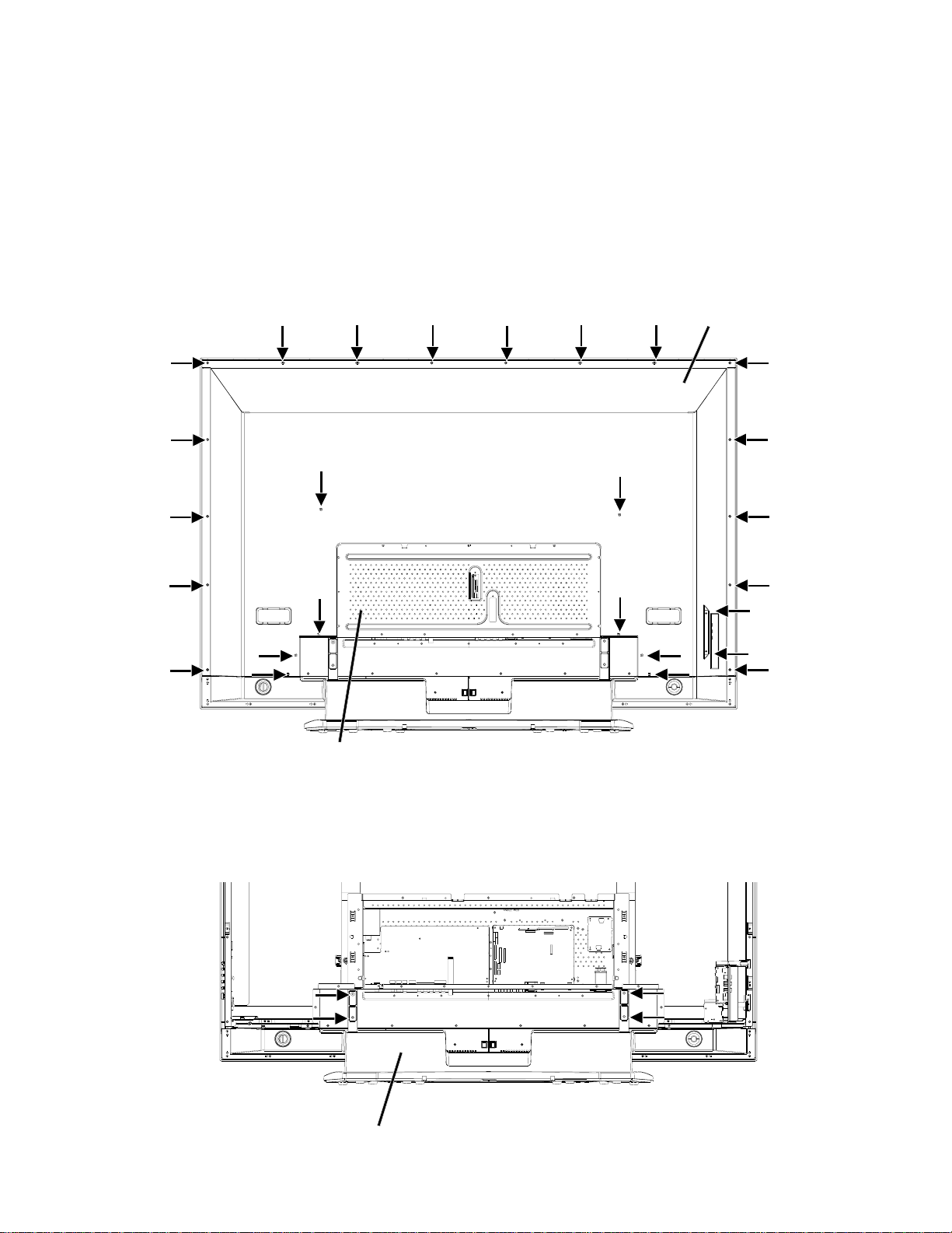
1-1: CABINET BACK/COVER BACK
1.
Remove the screw.
2.
Remove the Cabinet Back and Cover Back.
Cabinet Back
Cover Back
1-2: STAND ASS'Y
Spread a sheet on the plane table and place the PDP Module carefully with the panel face down.
1.
2.
Remove the screw.
Remove the Stand Ass'y.
3.
Stand Ass'y
B1-1
DISASSEMBLY INSTRUCTIONS
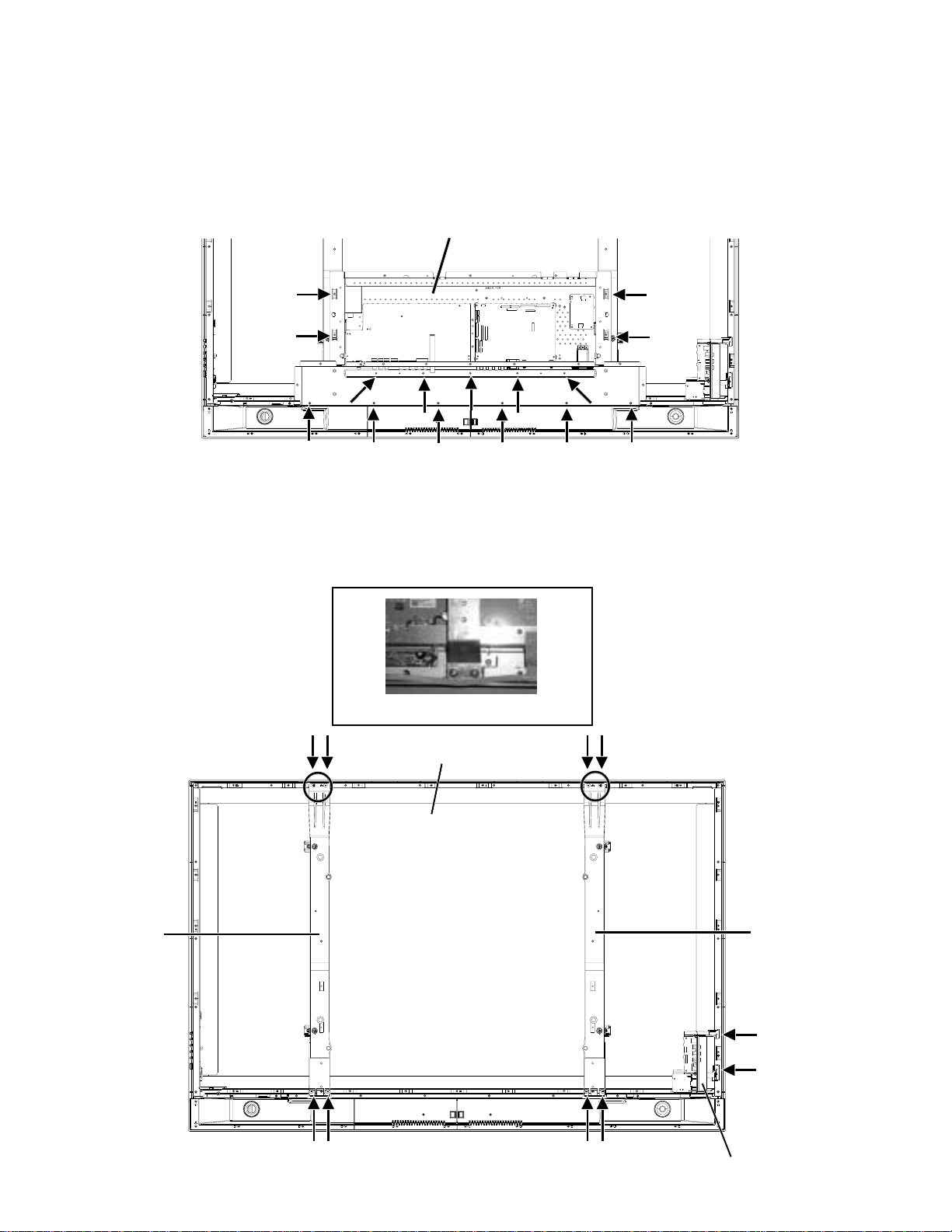
1-3: CHASSIS BLOCK
Disconnect the connector.
1.
2.
Remove the screw.
Remove the Chassis Ass'y.
3.
Chassis Ass'y
1-4: PDP MODULE
Remove the screw.
1.
Remove the Side Jack.
2.
3.
Hold the Frame Main carefully and remove the PDP Module.
NOTE
1.
When removing the PDP Module, raise the cushion carefully so that you do not scratch the face.
Frame Main
Raise the cushion.
PDP Module
Frame Main
B1-2
Side Jack
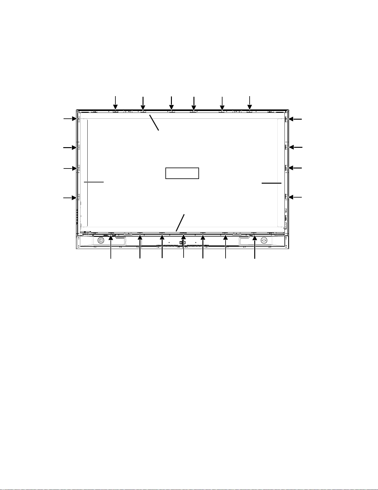
1-5: PDP FILTER
1.
Remove the screw.
Remove the Shield Main.
2.
3.
Remove the PDP Filter.
DISASSEMBLY INSTRUCTIONS
Shield Main L
Shield Main Top
PDP Filter
Shield Main R
Shield Main Bottom
B1-3
DISASSEMBLY INSTRUCTIONS
12345678901234567890123456789012123456789012345678
12345678901234567890123456789012123456789012345678
12
12
12
12
12
12
12
12
12
12
12
12
12
12
12
12
12
12
12
12
12
12
12
12
12
12
12
12
12
12
4
4
4
4
4
4
4
4
4
4
4
4
4
4
4
4
4
4
4
4
4
4
4
4
4
4
4
4
4
4
4
5
5
INSTALLATION METHOD OF PDP MODULE
NOTES FOR NEW PDP FILTER HANDLING
1.
When you handle the PDP Filter, you must wear gloves to avoid soiling it with sweat and dust.
2.
When you lift the PDP Filter, use the palm of your hand. Don’t pick it up with your fingers.
3.
The back side of the PDP Filter tends to get damaged, since there is no coating. Therefore, it needs to be put into the
packing box at the time of delivery, even if it is not being used at the time. Also, when you take it out of the packing box, be
careful not to rub the appearance.
4.
When the surface becomes dirty, use a cloth which is soft and dust free and wipe it in a circular motion.
When very dirty, lightly use alcohol on the cloth to wipe. Do not use alcohol for the back side.
5.
Do not apply it to direct sunlight, the characteristics may change.
6.
When you inspect for scratches and dirt, use a light to check for air bubbles on the PDP Filter surface.
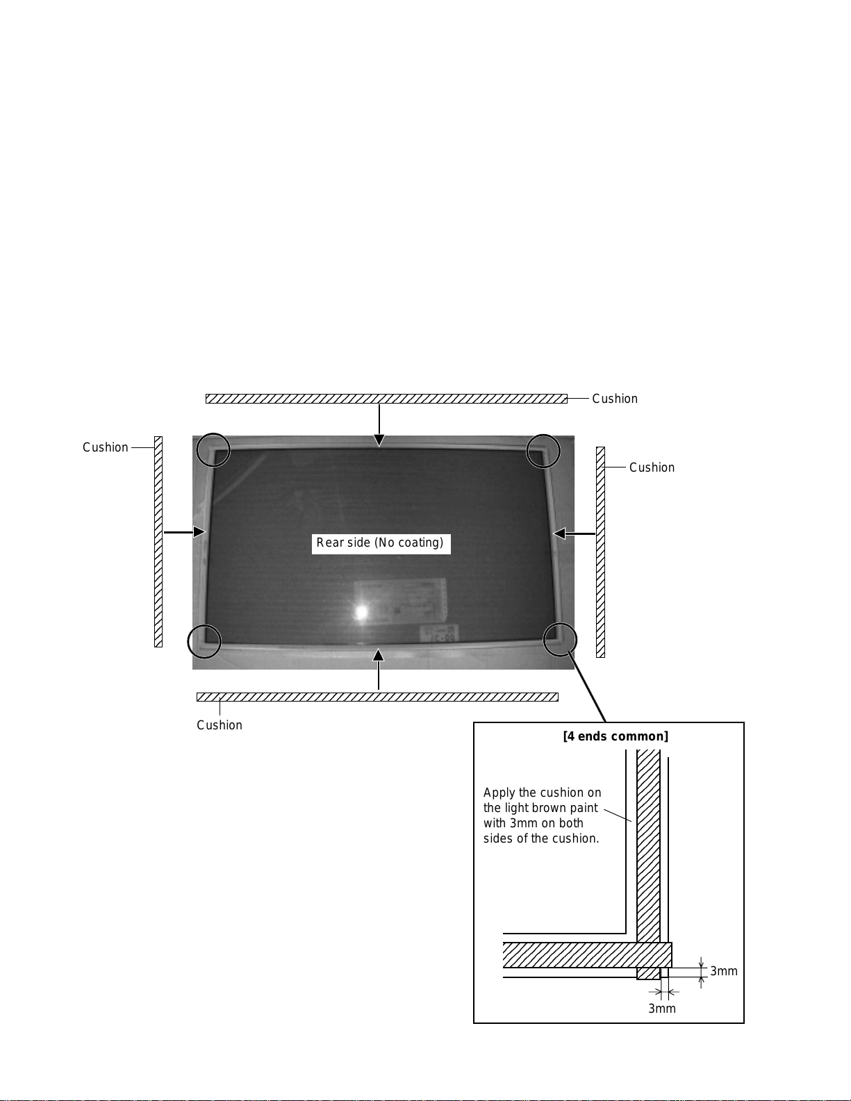
1-6: PDP FILTER (PREPARATION)
Fix the cushion. (Order the cushion new.)1.
Cushion
Cushion
Cushion
Rear side (No coating)
Cushion
B1-4
[4 ends common]
Apply the cushion on
the light brown paint
with 3mm on both
sides of the cushion.
23456789012345678901234
23456789012345678901234
23
23
23
23
23
23
23
23
23
23
23
23
23
23
23
23
23
23
23
23
23
23
23
23
23
23
23
23
23
23
23
3mm
3mm
DISASSEMBLY INSTRUCTIONS
NOTES FOR NEW PDP MODULE HANDLING
Handle the PDP Module with 2 people.
1.
There is a step difference between the cover and the PDP Module, so when you remove the screws, place a cushion on it
2.
to keep the PDP Module from being scratched. Then remove the screws carefully.
When you remove the cover, do not scratch the FPC on both ends of PDP Module.
3.
Hold all four ends of the holder and be careful not to touch the glass area.
4.
Be careful not to damage the vacuum exhaust pipe.
5.
Moisture condensation may damage the PDP Module, so leave it in the service room for 48 hours.
6.
Reuse the cover, vinyl sheet and screws when returning the PDP Module.
7.
Vacuum Exhaust Pipe
FPC
B1-5
DISASSEMBLY INSTRUCTIONS
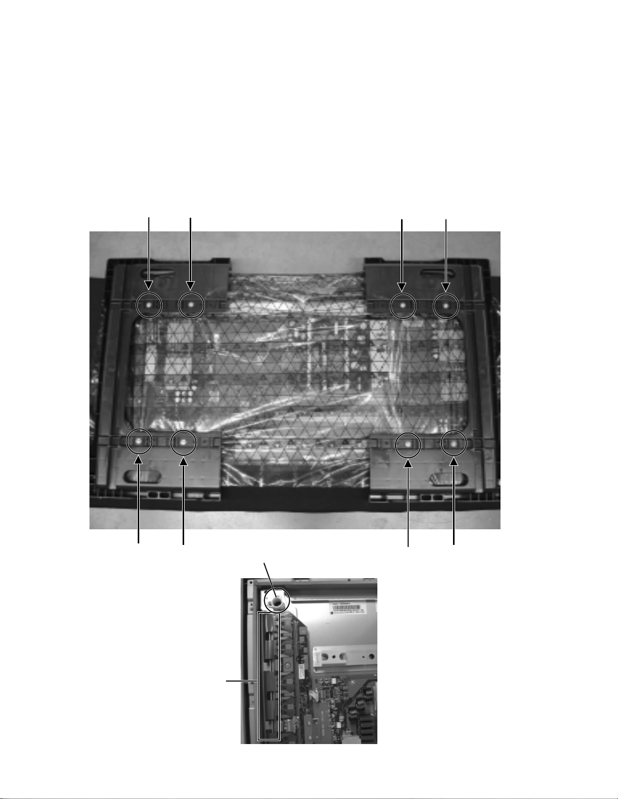
1-7: PDP MODULE (PREPARATION)
Remove the fixing screw of Power PCB. Then fix the Wiring Clip. (Use the clips on defective PDP Module)
1.
Fix the Cord Clip. (Use the clips on defective PDP Module)
2.
Fix the Wiring Clip. (Use the clips on defective PDP Module)
3.
Wiring Clip
Set SW501 (24V)
Cord Clip
45˚
Cord Clip
B1-6
DISASSEMBLY INSTRUCTIONS
3
3
3
3
3
3
3
3
3
3
3
3
3
3
3
3
3
3
3
3
5
1-8: PDP MODULE
Assemble the Frame Main. (Use the clips on defective PDP Module)
1.
Install the PDP Filter on the set.
2.
Install the Shield Main on the set.
3.
Hold the Frame Main carefully and install the New PDP Module on the set.
4.
Install the Side Jack on the set.
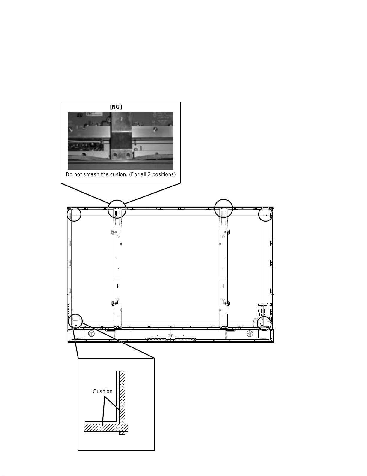
5.
[NG]
Do not smash the cusion. (For all 2 positions)
[4 ends common]
Cushion
2345678901234
Pile up the cushion.
2
2
2
2
2
2
2
2
2
2
2
2
2
2
2
2
2
2
2
2
B1-7
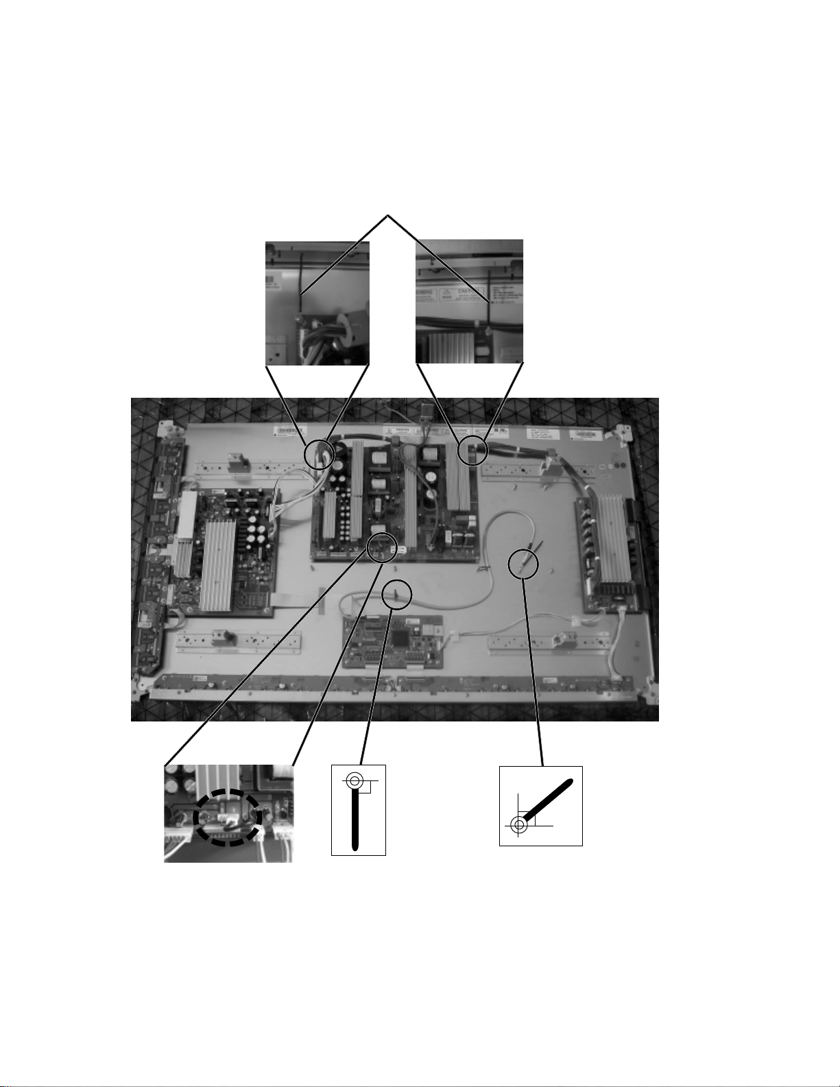
DISASSEMBLY INSTRUCTIONS
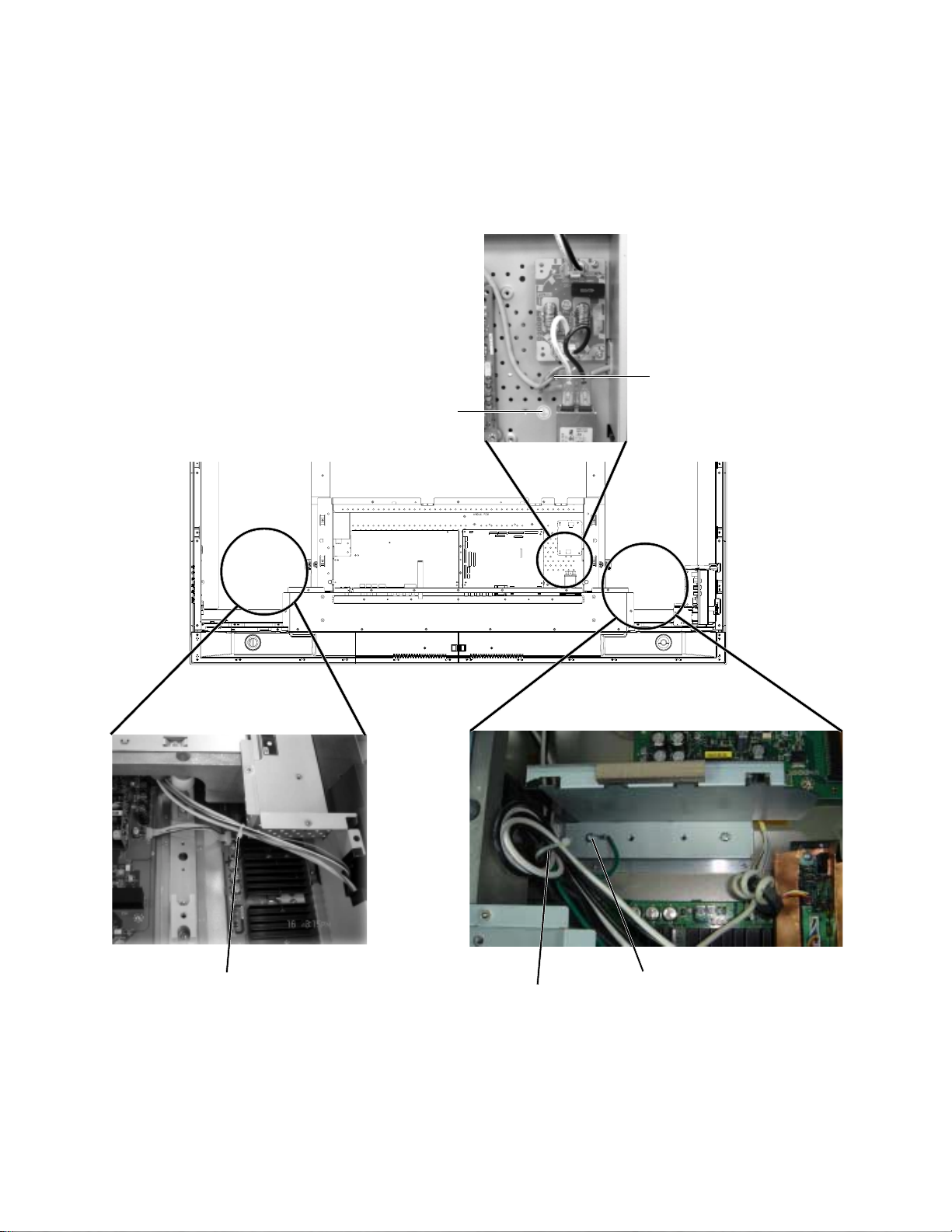
1-9: CHASSIS BLOCK
Do the wire fixing as shown in the photo, then install the Chassis Ass'y.
1.
Install the Stand Ass'y.
2.
Sheet Earth Mark
Earth wire of AC Inlet.
Band Cord Clamp
1-10: CABINET BACK/COVER BACK
1.
Check if the wire handlings are correct.
2.
Check if the cushion positions are correct.
3.
Check if the tape positions are correct.
4.
Install the Cabinet Back and Cover Back.
Band Cord Clamp
Earth wire
B1-8
DISASSEMBLY INSTRUCTIONS
2.
REMOVAL AND INSTALLATION OF
FLAT PACKAGE IC
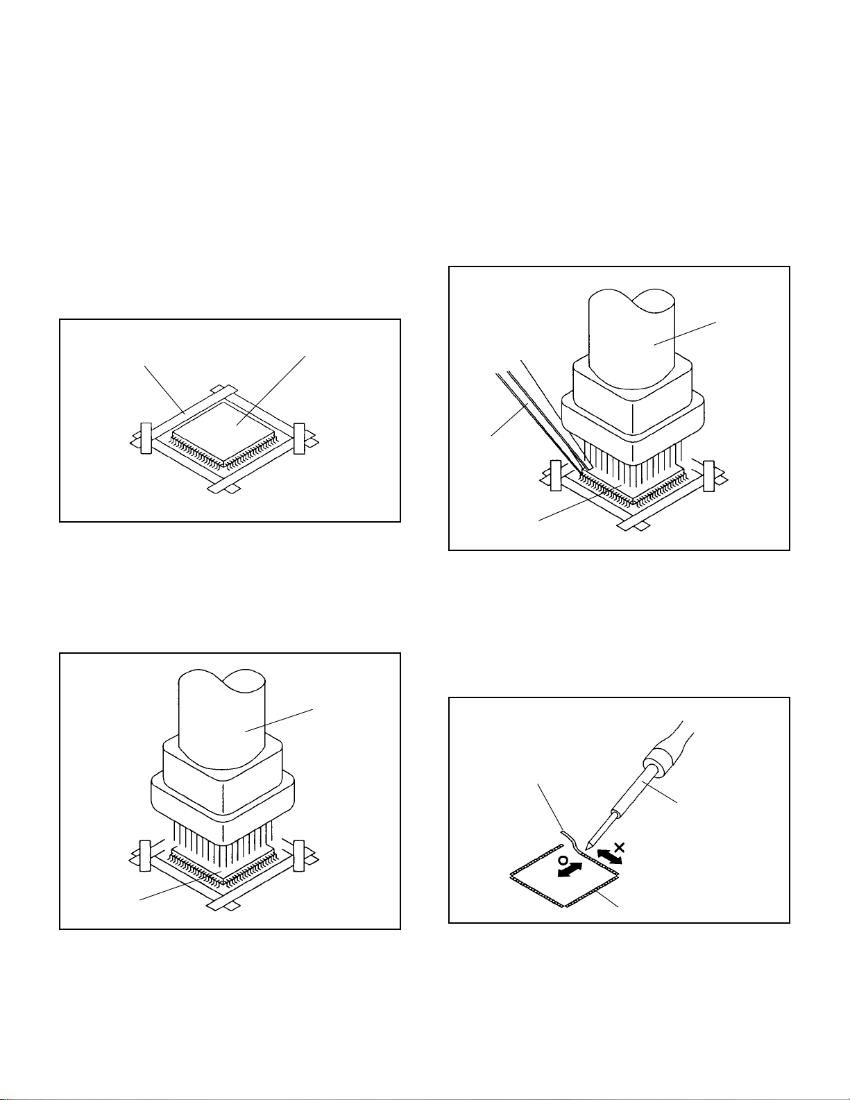
REMOVAL
Put Masking Tape (cotton tape) around the Flat Package
1.
IC to protect other parts from any damage.
(Refer to Fig. 2-1.)
NOTE
Masking is carried out on all the parts located within 10
mm distance from IC leads.
When IC starts moving back and forth easily after
3.
desoldering completely, pickup the corner of the IC using a
tweezers and remove the IC by moving with the IC
desoldering machine. (Refer to Fig. 2-3.)
NOTE
Some ICs on the PCB are affixed with glue, so be
careful not to break or damage the foil of each IC leads
or solder lands under the IC when removing it.
Blower type IC
desoldering
machine
Masking Tape
(Cotton Tape)
Heat the IC leads using a blower type IC desoldering
2.
IC
machine. (Refer to Fig. 2-2.)
NOTE
Do not rotate or move the IC back and forth , until IC
can move back and forth easily after desoldering the
leads completely.
Blower type IC
desoldering machine
Fig. 2-1
Tweezers
IC
Peel off the Masking Tape.4.
Absorb the solder left on the pattern using the Braided
5.
Shield Wire. (Refer to Fig. 2-4.)
NOTE
Do not move the Braided Shield Wire in the vertical
direction towards the IC pattern.
Fig. 2-3
Braided Shield Wire
Soldering Iron
IC
Fig. 2-2
IC pattern
Fig. 2-4
B2-1
DISASSEMBLY INSTRUCTIONS
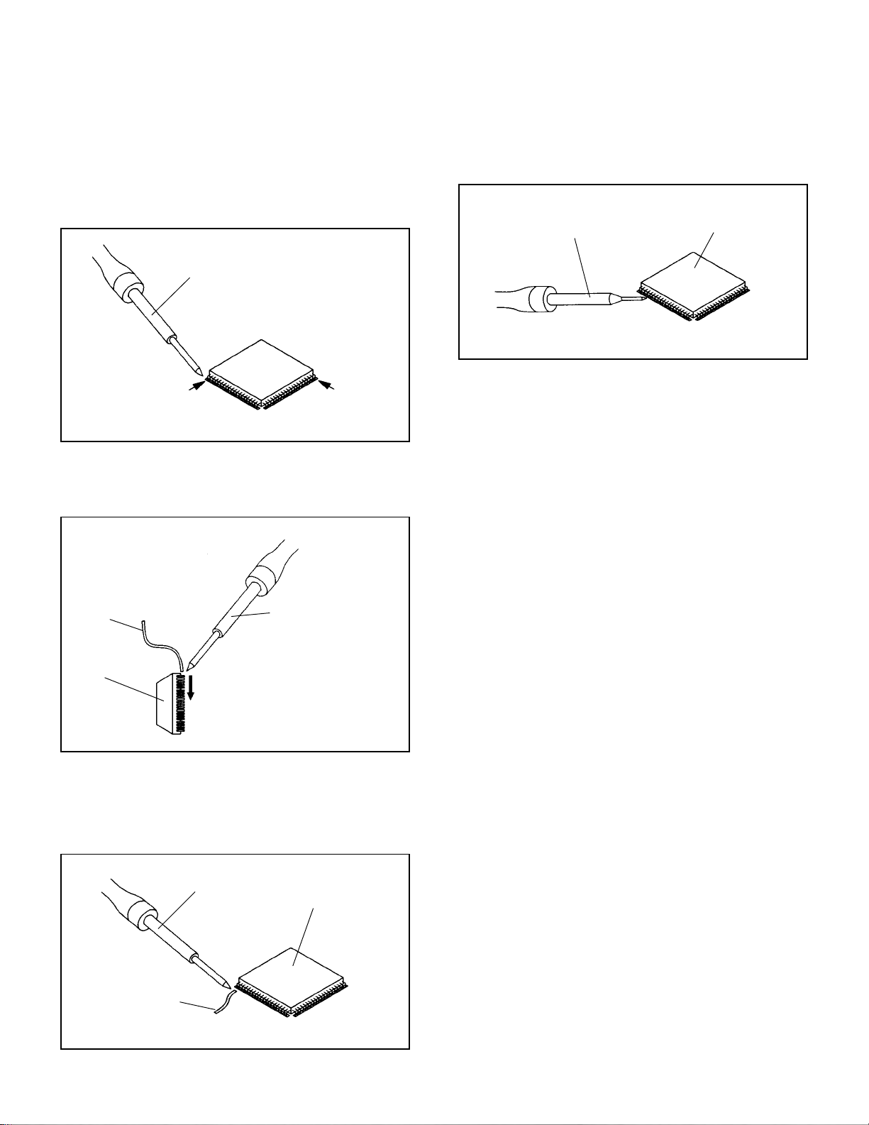
INSTALLATION
Take care of the polarity of new IC and then install the new
1.
IC fitting on the printed circuit pattern. Then solder each
lead on the diagonal positions of IC temporarily.
(Refer to Fig. 2-5.)
Soldering Iron
Solder temporarily
Supply the solder from the upper position of IC leads
2.
sliding to the lower position of the IC leads.
(Refer to Fig. 2-6.)
Solder temporarily
Fig. 2-5
When bridge-soldering between terminals and/or the
4.
soldering amount are not enough, resolder using a Thin-tip
Soldering Iron. (Refer to Fig. 2-8.)
Thin-tip Soldering Iron
IC
Fig. 2-8
Finally, confirm the soldering status on four sides of the IC
5.
using a magnifying glass.
Confirm that no abnormality is found on the soldering
position and installation position of the parts around the IC.
If some abnormality is found, correct by resoldering.
NOTE
When the IC leads are bent during soldering and/or
repairing, do not repair the bending of leads. If the
bending of leads are repaired, the pattern may be
damaged. So, always be sure to replace the IC in this
case.
Soldering IronSolder
IC
Supply soldering
from upper position
to lower position
Fig. 2-6
Absorb the solder left on the lead using the Braided Shield
3.
Wire. (Refer to Fig. 2-7.)
NOTE
Do not absorb the solder to excess.
Soldering Iron
IC
Braided Shield Wire
Fig. 2-7
B2-2
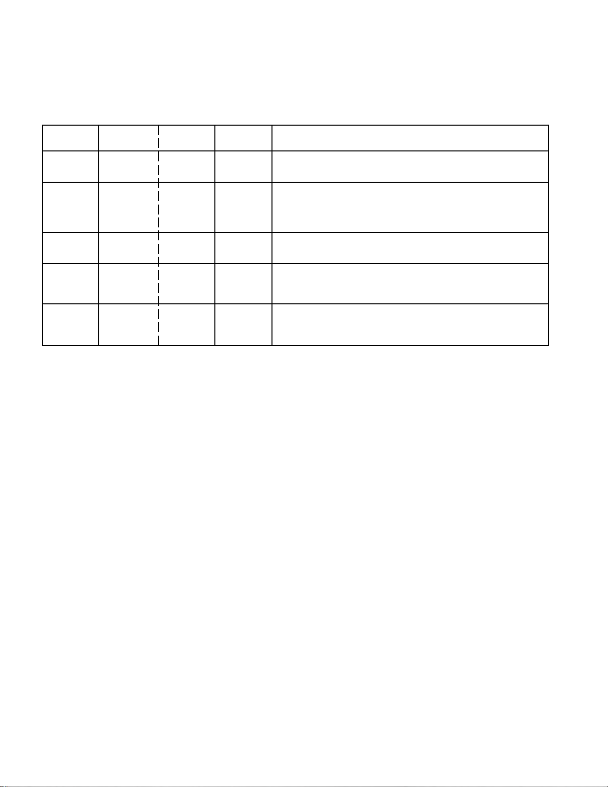
SERVICE MODE LIST
This unit is provided with the following SERVICE MODES so you can repair, examine and adjust easily.
To enter to the SERVICE MODE function, press and hold both buttons simultaneously on the main unit and on the remote
control for more than the standard time in the appropriate condition. (See below chart.)
Set
Condition
TV mode
TV mode
TV mode
ALL mode
ALL mode
Set Key Operations
VOL. DOWN
(Minimum)
VOL. DOWN
(Minimum)
VOL. DOWN
(Minimum)
VOL. DOWN
(Minimum)
VOL. DOWN
(Minimum)
Remocon
Key
0 2 sec.
1 2 sec.
6 2 sec.
8
9 2 sec.
Standard
Time
2 sec.
Releasing of V-CHIP PASSWORD.
Initialization of factory TV data.
NOTE:
Can be checked of the INITIAL DATA of MEMORY IC.
Refer to the "WHEN REPLACING EEPROM (MEMORY) IC".
Check of the SUM DATA, POWER ON total hours, MICON
VERSION on the screen.
Refer to the "WHEN REPLACING EEPROM (MEMORY) IC".
Display of the Adjustment MENU on the screen.
Refer to the "ELECTRICAL ADJUSTMENT" (On-Screen Display
Adjustment).
If you set factory initialization, the memories are reset
such as the channel setting, and the POWER ON total
hours.
C-1
WHEN REPLACING EEPROM (MEMORY) IC
CONFIRMATION OF CHECK SUM, POWER ON TOTAL HOURS, MICON VERSION .
Initial total of MEMORY IC, POWER ON total hours, MICON VERSION can be checked on the screen. Total hours are
displayed in 16 system of notation.
NOTE:
1.
2.
3.
4.
If you set a factory initialization, the total hours is reset to "0".
Please refer to "CONFIRMATION OF INITIAL DATA" when SUM DATA is not corresponding.
Turn on the POWER, and set to the TV mode.
Set the VOLUME to minimum.
Press both VOL. DOWN button on the set and Channel
button (8) on the remote control for more than 2 seconds.
After the confirmation of each check sum, POWER ON
total hours, MICON VERSION , turn off the power.
*1 DVP1 is different according to each set.
MICON Version
INIT : 61FB
VOLUME : 2E0E
ROM : 0000
ADC : C01F
DVP1 : EF2A
DVP2 : D172
PICENH : 5626
PDP ON :0001
OEC7164A_022
Initial setting data check sum.
VOLUME CURVE data check sum.
Rom correction data check sum.
AD CONVERTER data check sum.
SCALER data check sum.
DV1000 data check sum.
POWER ON total hours.
= (16 x 16 x 16 x thousands digit value)
+ (16 x 16 x hundreds digit value)
+ (16 x tens digit value)
+ (ones digit value)
CONFIRMATION OF INITIAL DATA
If a service repair is undertaken where it has been required to change the MEMORY IC, the following steps should be taken to
ensure correct data settings while making reference to INITIAL SETTING TABLE (Attached "INITIAL DATA").
Turn on the POWER, and set to the TV mode.
1.
Set the VOLUME to minimum.
2.
Press both VOL. DOWN button on the set and Channel button (6) on the remote control for more than 2 seconds.
3.
ADDRESS and DATA should appear as FIG 2.
ADDRESS DATA
INIT 0000 34
PDP ON 0001
OEC7164A_022
INIT :0000
ROM : 0000
VOLUME : 2E0E
FIG. 2
ADDRESS is now selected and should "blink". Using the UP/DOWN buton on the remote, step through the ADDRESS
4.
until required ADDRESS to be changed is reached.
Press RIGHT/LEFT button to select DATA. When DATA is selected, it will "blink".
5.
Again, step through the DATA using UP/DOWN button until required DATA value has been selected.
6.
Pressing RIGHT/LEFT button will take you back to ADDRESS for further selection if necessary.
7.
Repeat steps 4 to 6 until all data has been checked.
8.
When satisfied correct DATA has been entered, turn POWER off (return to STANDBY MODE) to finish DATA input.
9.
After the data input, set to the initializing of shipping.
Turn POWER on.
10.
Press both VOL. DOWN button on the set and Channel button (1) on the remote control for more than 2 seconds.
11.
After the finishing of the initializing of shipping, the unit will turn off automatically.
12.
The unit will now have the correct DATA for the new MEMORY IC.
C-2
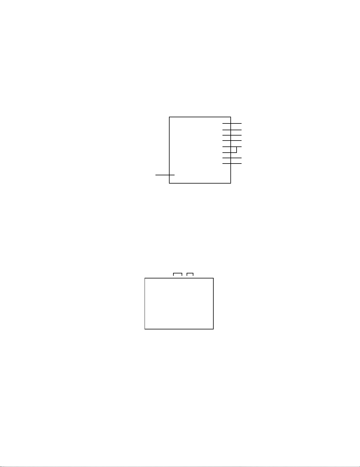
FUNCTION OF PCB
YDRV TOP
YDRV BOT
Y SUS
XRLT
42 SANKEN PSU
POWER
Z SUS
XRRT
42 SANKEN PSU :
Y SUS :
Z SUS :
CTRL :
XRLT :
XRRT :
YDRV TOP :
YDRV BOT :
CTRL
A supplier which supplies voltage and current to each PCB and Panel.
According to the timing provided from Panel Control, switches FETs and
generates driving waveform signal which is provided to Y electrode through
Scan Driver IC of YDRV TOP and YDRV BOT.
According to the timing provided from Panel Control, switches FETs and
generates driving waveform signal which is provided to Z electrode through
Connector.
Controls Y electrode, Z electrode, and ADDRESS electrode.
Generates Address electrode and supplies to Address electrode by Driver IC.
Generates Address electrode and supplies to Address electrode by Driver IC.
Generates Scan electrode and supplies to Y electrode by Driver IC.
Generates Scan electrode and supplies to Y electrode by Driver IC.
C-3

ELECTRICAL ADJUSTMENTS
1. ADJUSTMENT PROCEDURE
Read and perform these adjustments when repairing the
circuits or replacing electrical parts or PCB assemblies.
CAUTION
•
Use an isolation transformer when performing any
service on this chassis.
•
When removing a PCB or related component, after
unfastening or changing a wire, be sure to put the wire
back in its original position.
•
When you exchange IC and Transistor with a heat sink,
apply silicon grease on the contact section of the heat
sink. Before applying new silicon grease, remove all the
old silicon grease. (Old grease may cause damage to the
IC and Transistor).
Prepare the following measurement tools for electrical
adjustments.
1. Pattern Generator
2. BASIC ADJUSTMENTS
On-Screen Display Adjustment
1.2.Set the VOLUME to minimum.
Press the VOL. DOWN button on the set and the
channel button (9) on the remote control for more than
2 seconds to display adjustment mode on the screen as
shown in Fig. 2-1.
TV
AUTO
01 H POSI OSD
3.
Use the Channel UP/DOWN button or Channel button
(0-9) on the remote control to select the options shown
in Fig. 2-2.
4.
Press the MENU button on the remote control to end
the adjustments.
5.
To display the adjustment screen for AV, YUV, HDMI
and PC mode, press the INPUT button on the remote
control to set to the AV, YUV, HDMI and PC mode.
Press the VOL.DOWN button on the set and the
channel (9) on the remote control for more than 2
seconds.
180
Fig. 2-1
NO.
FUNCTION
NO.
H POSI OSD
01
V POSI OSD
02
R DRIVE (N)
03
R CUT OFF (N)
04
G DRIVE (N)
05
G CUT OFF (N)
06
B DRIVE (N)
07
B CUT OFF (N)
08
R DRIVE (C)
09
R CUT OFF (C)
10
G DRIVE (C)
11
G CUT OFF (C)
12
B DRIVE (C)
13
B CUT OFF (C)
14
R DRIVE (W)
15
R CUT OFF (W)
16
G DRIVE (W)
17
G CUT OFF (W)
18
FUNCTION
19
B DRIVE (W)
20
B CUT OFF (W)
22
H POSI 60Hz
24
V POSI 60Hz
28
BRIGHT CENT
29
BRIGHT MAX
30
BRIGHT MIN
31
TINT
35
CONTRAST CENTER
36
CONTRAST MAX
37
CONTRAST MIN
38
COLOR CENT
39
COLOR MAX
40
COLOR MIN
Fig. 2-2
2-1: CONTRAST MAX
1.
Receive the monoscope pattern. (VIDEO Input)
2.
Press the INPUT button on the remote control to set to the
AV mode.
3.
Activate the adjustment mode display of Fig. 2-1 and press
the channel button (36) on the remote control to select
"CONTRAST MAX".
4.
Press the VOL UP/DOWN button on the remote control
until the contrast step No. becomes "155".
5.
Check if the picture is normal.
6.
Receive the monoscope pattern. (RF Input)
7.
Press the INPUT button on the remote control to set to the
TV mode.
8.
Activate the adjustment mode display of Fig. 2-1 and press
the channel button (36) on the remote control to select
"CONTRAST MAX".
9.
Press the VOL UP/DOWN button on the remote control
until the contrast step No. becomes "145".
10.
Check if the picture is normal.
11.
Receive the digital broadcast. (RF Input)
12.
Perform the above adjustments 3 and 5.
13.
Playback the DVD(480i) disc. (COMPONENT Input)
14.
Press the INPUT button on the remote control to set to the
YUV mode.
15.
Activate the adjustment mode display of Fig. 2-1 and press
the channel button (36) on the remote control to select
"CONTRAST MAX".
16.
Press the VOL UP/DOWN button on the remote control
until the contrast step No. becomes "162".
17.
Check if the picture is normal.
18.
Playback the DVD(480i) disc. (HDMI Input)
19.
Press the INPUT button on the remote control to set to the
HDMI mode.
20.
Activate the adjustment mode display of Fig. 2-1 and press
the channel button (36) on the remote control to select
"CONTRAST MAX".
21.
Press the VOL UP/DOWN button on the remote control
until the contrast step No. becomes "130".
22.
Check if the picture is normal.
D-1

ELECTRICAL ADJUSTMENTS
2-2: WHITE BALANCE
1.
Place the set in Aging Test for more than 15 minutes.
2.
Receive the gray scale pattern from the Pattern
Generator.
3.
Press the INPUT button on the remote control to set to
the AV mode.
4.
Using the remote control, set the brightness and contrast
to normal position.
5.
Activate the adjustment mode display of Fig. 2-1 and
press the channel button (03) on the remote control to
select “R DRIVE (N)”.
6.
Press the CH. UP/DOWN button on the remote control to
select the “R CUTOFF (N)”, “B.DRIVE(N)”, “B CUTOFF
(N)”, “R DRIVE (C)”, “R CUTOFF (C)”, “B.DRIVE(C)”, “B
CUTOFF (C)”, “R DRIVE (W)”, “R CUTOFF (W)”,
“B.DRIVE(W)”and “B CUTOFF (W)”.
7.
Adjust the VOL. UP/DOWN button on the remote control
to whiten the R CUTOFF (N), B.DRIVE(N), B CUTOFF
(N), R DRIVE (C), R CUTOFF (C), B.DRIVE(C), B
CUTOFF (C), R DRIVE (W), R CUTOFF (W),
B.DRIVE(W) and B CUTOFF (W) at each step tone
sections equally.
8.
Perform the above adjustments 6 and 7 until the white
color is looked like a white.
2-3: BRIGHT CENT
1.
Receive the monoscope pattern. (VIDEO Input)
2.
Press the INPUT button on the remote control to set to
the AV mode.
3.
Set the screen mode to FULL.
4.
Using the remote control, set the brightness and contrast
to normal position.
5.
Activate the adjustment mode display of Fig. 2-1 and
press the channel button (28) on the remote control to
select "BRIGHT CENT".
6.
Press the VOL. UP/DOWN button on the remote control
until the white 8.1% is starting to be visible.
7.
Receive the monoscope pattern. (RF Input)
8.
Press the INPUT button on the remote control to set to
the TV mode. Then perform the above adjustments 4~6.
9.
Receive the digital broadcast. (RF Input)
10.
Perform the above adjustments 4~6.
11.
Playback the DVD(480i) disc. (COMPONENT Input)
12.
Press the INPUT button on the remote control to set to
the YUV mode. Then perform the above adjustments
4~6.
13.
Playback the DVD(480i) disc. (HDMI Input)
14.
Press the INPUT button on the remote control to set to
the HDMI mode. Then perform the above adjustments
4~6.
D-2

p
ELECTRICAL ADJUSTMENTS
2-4: Confirmation of Fixed Value (Step No.)
Please check if the fixed values of each the adjustment items are set correctly referring below. (TV/AV/YUV/HDMI/PC)
YUV PCHD-MI
TV AV
480i 480p 720p 1080i 480i 480p 720p 1080i 60*480 800*600 1024*768 1280*768 1280*720 848*480 1360*768
NO. FUNCTION
1 H POSI OSD 180 180 180 180 180 180 180 180 180 180 180 180 180 180 180 180 180
2 V POSI OSD 80 80 80 80 80 80 80 80 80 80 80 80 80 80 80 80 80
3 R DRIVE (N) 116 116 127 127 127 127 127 127 127 127 120 120 120 120 120 120 120
4 R CUT OFF (N) 133 133 128 128 128 128 128 128 128 128 ... ... ... ... ... ... ...
5 G DRIVE (N) 128 128 128 128 128 128 128 128 128 128 122 122 122 122 122 122 122
6 G CUT OFF (N) 128 128 128 128 128 128 128 128 128 128 ... ... ... ... ... ... ...
7 B DRIVE (N) 120 120 118 118 118 118 118 118 118 118 128 128 128 128 128 128 128
8 B CUT OFF (N) 136 136 134 134 134 134 134 134 134 134 ... ... ... ... ... ... ...
9 R DRIVE (C) 112 112 118 118 118 118 118 118 118 118 ... ... ... ... ... ... ...
10 R CUT OFF (C) 134 134 128 128 128 128 128 128 128 128 ... ... ... ... ... ... ...
11 G DRIVE (C) 128 128 128 128 128 128 128 128 128 128 ... ... ... ... ... ... ...
12 G CUT OFF (C) 128 128 128 128 128 128 128 128 128 128 ... ... ... ... ... ... ...
13 B DRIVE (C) 123 123 130 130 130 130 130 130 130 130 ... ... ... ... ... ... ...
14 B CUT OFF (C) 135 135 131 131 131 131 131 131 131 131 ... ... ... ... ... ... ...
15 R DRIVE (W) 115 115 127 127 127 127 127 127 127 127 ... ... ... ... ... ... ...
16 R CUT OFF (W) 135 135 127 127 127 127 127 127 127 127 ... ... ... ... ... ... ...
17 G DRIVE (W) 128 128 128 128 128 128 128 128 128 128 ... ... ... ... ... ... ...
18 G CUT OFF (W) 128 128 128 128 128 128 128 128 128 128 ... ... ... ... ... ... ...
19 B DRIVE (W) 109 109 109 109 109 109 109 109 109 109 ... ... ... ... ... ... ...
20 B CUT OFF (W) 137 137 137 137 137 137 137 137 137 137 ... ... ... ... ... ... ...
22 H POSI 60Hz 282 282 282 142 312 260 278 140 268 218 110 110 230 190 190 110 365
24 V POSI 60Hz 24 24 24 24 24 24 24 24 24 24 22 22 22 20 20 22 20
28 BRIGHT CENT 107 107 107 115 115 115 95 95 95 95 50 50 50 50 50 50 50
29 BRIGHT MAX 185 185 185 185 185 185 185 185 185 185 100 100 100 100 100 100 100
30 BRIGHT MIN 60 60 60 60 60 60 60 60 60 60 30 30 30 30 30 30 30
31 TINT 117 117 121 126 126 126 123 123 123 123 ... ... ... ... ... ... ...
35 CONTRAST CENTER 128 128 128 128 128 128 128 128 128 128 130 130 130 130 130 130 130
36 CONTRAST MAX 145 155 162 155 155 155 130 130 130 130 150 150 150 150 150 150 150
37 CONTRAST MIN 70 70 70 70 70 70 70 70 70 70 90 90 90 90 90 90 90
38 COLOR CENT 80 88 106 56 56 56 78 78 78 78 ... ... ... ... ... ... ...
39 COLOR MAX 180 180 180 180 180 180 180 180 180 180 ... ... ... ... ... ... ...
40 COLOR MIN 0000000000.....................
Ste
No.
VGA SVGA XGA WVGA WXGA
WXGA
D-3 D-4

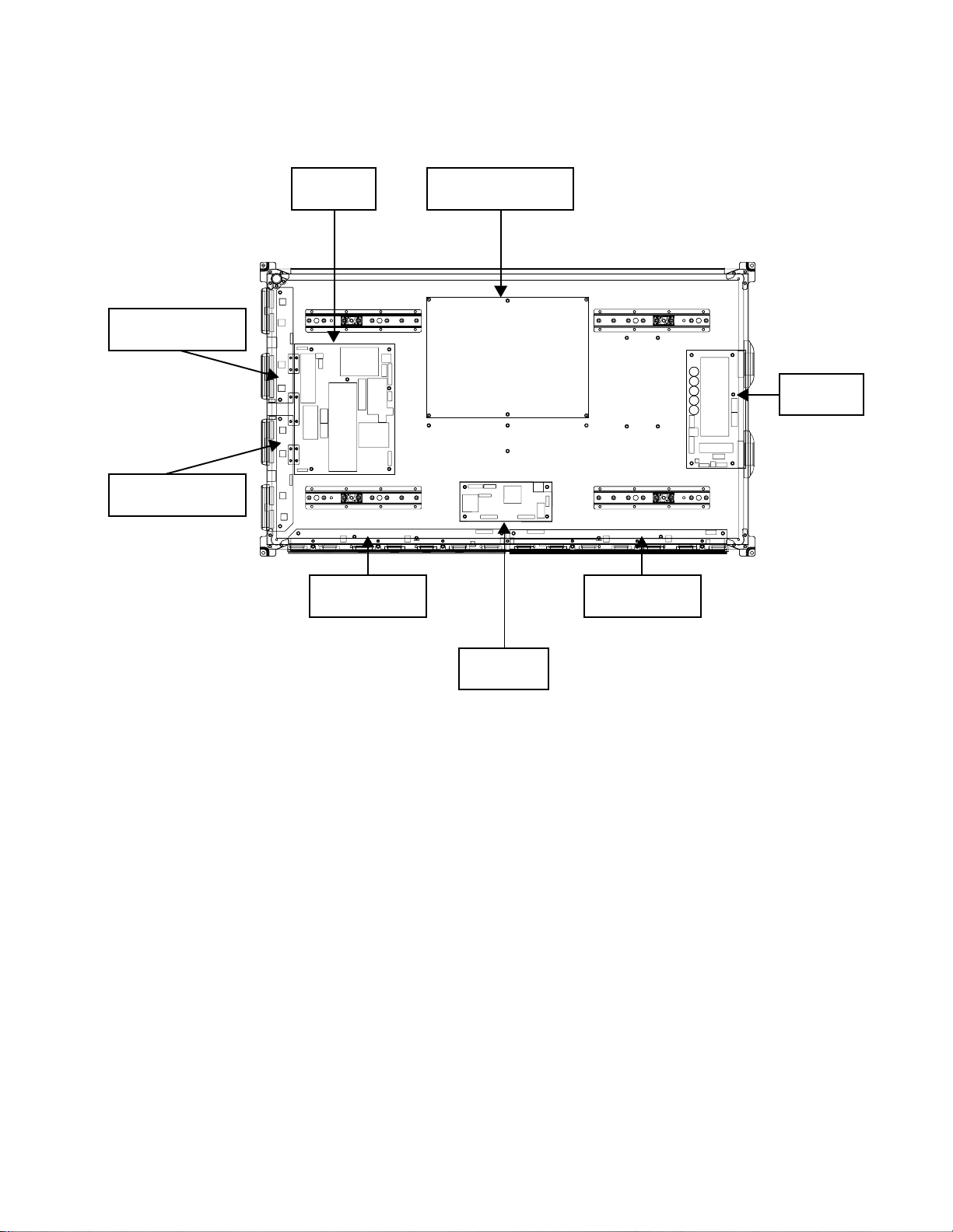
ELECTRICAL ADJUSTMENTS
3. ELECTRICAL ADJUSTMENT PARTS LOCATION GUIDE (WIRING CONNECTION)
PDP PANEL
SPEAKER
SPEAKER
J2275
CP301
CP303
J4201
CP901
J4205
J4211
AV PCB
CP2251
REMOCON PCB
OPERATION PCB
CP3801
CP4201
J4204
CP3803
CP3807
CP2203
TU5800
CP3802
CP3804
CP4202
CP4204
CP4203
CD4203
CD4204
CP2200
CP802
CP803
CP7202
CP4302
SCALER PCB
SIDE JACK PCB
J4209
J4208
J4207
CP4200
J4206
CP3900
CP3901
CP3201
J4301
CP3601
CP3602
CP3603
J3601
D-5
FILTER PCB
CD3810
AC IN

POWER DOES NOT TURN ON
TROUBLESHOOTING GUIDE
IS F3900 BROKEN ?
NO
IS THERE VOLTAGE
AT PIN 11 OF CP3201
5V ?
YES
IS THERE VOLTAGE
AT PIN 2 OF IC3804
AT3.3V ?
YES
CHANGE SCALER PCB.
YES
NO
NO
CHANGE F3900.
CHECK CP3201 AND
CP3804.
CHECK IC3804 AND
PERIPHERAL CIRCUIT.
OR CHANGE AV PCB.
E-1

THE PICTURE DOES NOT
APPEAR (1).
TROUBLESHOOTING GUIDE
IS CD7206 CONNECTED ?
YES
IS THERE SIGNAL
AT IC7202 ?
YES
IS THERE SIGNAL
AT IC7501 ?
YES
CHECK IC801.
OR CHANGE SCALER PCB.
NO
NO
NO
CONNECT CP7202.
CHANGE IC7202.
CHANGE IC7501.
E-2

THE PICTURE DOES NOT
APPEAR (2).
TROUBLESHOOTING GUIDE
IS THERE SIGNAL
AT IC4201 ?
YES
IS CD4203 CONNECTED
AND IS THERE SIGNAL ?
YES
CHECK IC801 AND
PERIPHERAL CIRCUIT.
NO
NO
CHECK IC4201 AND
PERIPHERAL CIRCUIT.
CONNECT CD4203.
CHECK IC4201 AND
PERIPHERAL CIRCUIT.
E-3

THE PICTURE APPEARS, BUT
THE AUDIO DOES NOT
APPEAR.
TROUBLESHOOTING GUIDE
IS CD301 AND CD303
CONNECTED ?
YES
IS THERE SIGNAL
CD301 AND CD303 ?
NO
IS THERE SIGNAL
AT PINS 11 AND 15
OF IC301 ?
NO
IS THERE SIGNAL
AT PINS 27 AND 28
OF IC904 ?
NO
YES
YES
NO
CONNECT CD301 AND CD303.
CHANGE SP301 AND SP302.
CHECK IC301 AND
PERIPHERAL CIRCUIT.
CHECK IC904 AND
PERIPHERAL CIRCUIT.
YES
CHANGE AV PCB.
E-4

THE COLOR DOES NOT
APPEAR.
TROUBLESHOOTING GUIDE
IS SETTING OF
COLOR NORMAL ?
YES
IS THE COLOR
SIGNAL RECEIVED ?
YES
IS THERE SIGNAL
AT IC801 ?
YES
IS THERE SIGNAL
AT IC2101 ?
NO
NO
NO
NO
CHANGE THE SETTING OF
COLOR.
RECEIVE THE COLOR SIGNAL.
CHECK IC801 AND
PERIPHERAL CIRCUIT.
CHECK IC2101 AND
PERIPHERAL CIRCUIT.
YES
CHANGE SCALER PCB.
E-5

ON SCREEN DISPLAY DOES
NOT APPEAR.
TROUBLESHOOTING GUIDE
IS THERE SIGNAL AT
PINS 2, 3, 4 AND 5 OF
IC101 ?
YES
IS THE COLOR SIGNAL
AT PINS 57, 58, 59 AND
60 OF IC801 ?
YES
CHANGE SCALER PCB.
NO
NO
CHECK IC101 AND
PERIPHERAL CIRCUIT.
CHECK IC801 AND
PERIPHERAL CIRCUIT.
E-6

INTERFACE
AV SWITCH/AV
SWITCH2/AV
JACK/STEREO/
SOUND AMP/
JACK
DIGITAL RGB
DDVS
DDHS
DDCK
VGA_HS
VGA_VS
SW_CVBS
SW_Y
SW_C
SCART1_B_IN
SCART1_G_IN
SCART1_R_IN
AUDIO_MUTE
SCL
SDA
SCALER/LVDS/MICON/ADC/VIDEO ENHANCER/REGULATOR BLOCK DIAGRAM
64
A/D CONVERTER
66
67
IC2101
MST9883C-LF-110
30
31
54
48 43
DIGITAL
24bit RGB
DDHS, DDVS, DDCK
56
57
58
27
28
13
42
31
SCALER
IC801
R8J66607A72FP
33 44
21
MICON
IC101
OEC7164A
57
60
2
5
DIGITAL
24bit RGB
DCLK2,DHS,DVS,DEN
84
X801
54MHz
85
4SI_SDA_IN/4SI_SCL
4SI_CHIP_SE/4SI_SDA_OUT
54
54
53
18
VIDEO ENHANCER
IC7501
DV1000-75
DIGITAL 24bit RGB
DHS1,DVS1,DENO
LVDS IC
IC7202
ICSV385AGLFT
EEPROM IC 256K
IC103
AT24C256N-10SU-2.7
6
EEP_SCL
5
EEP_SDA
EEPROM IC 256K
IC104
AT24C256N-10SU-2.7
6
EEP_SCL
5
EEP_SDA
TX OUT0~3+
TX OUT0~3TXCLKOUT+
TXCLKOUT-
POWER_ON-H
PDP PANEL
V801
PDP42X3
TUNER/DIGITAL/
POWER
PSU_5VD
LCD_H
POWER_FAIL
LCD_ON
AT+3.3V
P.CON+3.8V
P.CON+3.3V REG
IC3201
BA00BC0WFP-E2
P.CON+1.5V REG
IC3202
BD7820FP-E2
P.CON+1.8V REG
IC3203
BD7820FP-E2
SCART2 OUT CVBS SW
6
4
IC8103
MM1501XNRE
2
1
1 4
2
2
1 4
IC102
1
74
90 17 89 10 76
16
OS2251
1
3
RESET
OPE AMP
SCALER_H
IC2275
NJM4580V (TE1)
3 7
Q2275~Q2277
SW
IR PASS THROUGH
J2275
2
L
R
3
2
SYSTEM RESET
2
1
D105
4
P.CON+3.3V
P.CON+1.5V
P.CON+1.8V
PST3229NR
F-1 F-2

AV SWITCH/AV SWITCH2/AV JACK/STEREO/SOUND AMP/JACK BLOCK DIAGRAM
TUNER/POWER
SCALER/LVDS/
MICON/ADC/VIDEO
ENHANCER/
REGULATOR
SCALER/LVDS/
MICON/ADC/VIDEO
ENHANCER/
REGULATOR
MICON2
TUNER/
POWER
YELLOW
WHITE
S_VIDEO JACK
J4206
SW_CVBS
SW_Y
SW_C
PC AUDIO IN
J4301
PC_A_IN_L
PC_A_IN_R
HDMI AUDIO IN
J3601
DVI_A_IN_L
DVI_A_IN_R
AUDIO_MUTE
CP901
4
HDMI_I2SSCK
3
HDMI_I2SSDO
2
HDMI_I2SWS
TUNER_VIDEO
SOUND+B
J4207
J4208
RED
J4209
SCL
SCA
2
3
SCL
SDA
AV SW
IC4201 AN15853B-E1
SIDE_V_IN
2
2
2
3
4
4
2
18
SIDE_A_IN_L
15
SIDE_A_IN_R
17
SIDE_Y_IN
11
SIDE_C_IN
13
SCL
25
24
SDA
SW_A_R
28
30
SW_A_L
31
SW_CVBS
SW_Y
33
35
SW_C
16 TUNER_V
5
3
7
YUV/HDMI/DVI Lch SW
IC4304 NJM2534V (TE2)
YUV/HDMI/DVI Rch SW
IC4305 NJM2534V (TE2)
AV1_IN
S1_Y_IN
S1_C_IN
AV1_A_IN_L
AV1_A_IN_R
S2_Y_IN
S2_C_IN
AV2_IN
YUV1_A_IN_R
YUV1_A_IN_L
YUV2_A_IN_L
YUV2_A_IN_R
5
3
2
3
2
4
6
3
5
20
22
9
12
10
19
21
STEREO
IC904 MSP4440G-QA-C13-100
SW_A_IN_L56
SW_A_IN_R
57
SW2_A_IN_L
53
7
SW2_A_IN_R
54
I2C_CL
2
3
I2C_DA
36
VARIOUT_R
37
VARIOUT_L
AV2_A_IN_L
AV2_A_IN_R
XTAL_IN
XTAL_OUT
50
51
71
72
X901
18.432MHz
COMPONENT SW
IC4204
NJM2584AM(TE1)
3
5
6
SW
IC8104
NJM2584AM(TE1)
9
1
14
11 8
5
6
3
16
14
11
16
Y
9
U
V
1
Y
8
U
V
5
67
SIF
AUDIO_OUT_JACK
J4201
4
I2S_CL
I2S_DA_IN1
7
I2S_WS
5
SPOUT_R
SPOUT_L
27
28
SOUND AMP
IC301 TA2024-ASE
15
INV2
11
INV1
33
VDDA
VDD1
30
12
MUTE
VDD1
29
VDD2
26
25 VDD2
OUTP1
OUTM1
OUTM2
OUTP2
31
28
27
24
INPUT 1/2
J4205
14
3
4
17
20
9
10
15
18
22
AUDIO_IN 4/5
J4204
5
2
3
7
CS_IN 4/5
J4211
2
5
8
3
6
9
SCART1_R_IN
SCART1_G_IN
SCART1_B_IN
SIF
VGA_B
VGA_G
VGA_R
SCALER/LVDS/
MICON/ADC/VIDEO
ENHANCER/
REGULATOR
TUNER/POWER
INTERFACE
SPEAKER
SP304
SPEAKER
SP302
SPEAKER
SP301
F-3
SPEAKER
SP303
F-4

TUNER/POWER BLOCK DIAGRAM
TU5800
CP3801
1
SOUND+B
2
CP3803
1
2
3
7
8
CP3802
1
CP3804
1
2
3
5
LCD_ON
6
SOUND+B
5VSC
5VSC
5VSC
12VSC
12VSC
9VSC
POWER FAIL
LCD_H
AT+5V
5VD
DC-DC CONVERTER
IC3803
BD9300FV-E2
8
5
P.CON+3.8V
IC3808
BA7810T-V5
2
P.CON32V REG
LA7995M-TLM
4
IC3805
7
14
+B
15
+32V
11
1
SDA
10
SCL
2
V_OUT
17
AT+3.3V REG
PQ070XF01SZH
SIF OUT
143
IC3804
SCL
SDA
TUNER VIDEO
SIF
SOUND+B
AT+3.3V
AT+5V
P.CON+12V
P.CON+3.8V
P.CON+9V
AV SWITCH/
AV SWITCH2/
AV JACK/STEREO/
SOUND AMP/JACK
AV SWITCH/
AV SWITCH2/AV JACK/
STEREO/
SOUND AMP/JACK
SCALER/LVDS/
MICON/ADC/ADC2/
AV SWITCH1/
REGULATOR
PSU_5VD
LCD_ON
LCD_H
POWER_FAIL
F-6F-5

INTERFACE BLOCK DIAGRAM
HDMI
CONNECTOR
CP3601
19 DET
18
POWER
16
SDA
15
SCL
CLK-
12
10
CLK+
9D0-
D0+
7
D1-
6
D1+
4
D2-
3
1
D2+
HDMI
CONNECTOR
CP3603
19 DET
18
POWER
16
SDA
15
SCL
CLK-
12
10
CLK+
9D0-
D0+
7
D1-
6
D1+
4
D2-
3
1
D2+
D-SUB
CP4302
1
VGA-R
2
VGA-G
3
VGA-B
VGAHS
13
14
VGAVS
EEP_ROM
IC3609 BR24L02F-WE2
5
SDA
6
SCL
7
WP
8
VCC
VGA-R
VGA-G
VGA-B
VGA_HS
VGA_VS
EEP_ROM
IC3606 BR24L02F-WE2
5
SDA
6
SCL
7
WP
8
VCC
Q3615
BUFFER
Q3603
BUFFER
Q3619
SW
L3601
ACM2012D-900-2P
1
2
L3602
ACM2012D-900-2P
1
2
L3608
ACM2012D-900-2P
1
2
L3606
ACM2012D-900-2P
1
2
AV SWITCH/AV
SWITCH2/AV JACK/
STEREO/SOUND
AMP/JACK
SCALER/LVDS/
MICON/ADC/VIDEO
ENHANCER/
REGULATOR
4
3
4
3
4
3
4
3
Q3616
BUFFER
Q3604
BUFFER
Q3613
SW
L3603
ACM2012D-900-2P
1
2
L3604
ACM2012D-900-2P
1
2
L3607
ACM2012D-900-2P
1
2
L3605
ACM2012D-900-2P
1
2
4
3
4
3
4
3
4
3
HDMI INTERFACE
IC3605 SII9021CTU
DSDA1
29
DSCL1
30
DSDA0
31
DSCL0
32
39
R0XC-
40
R0XC+
R0X0-
43
44
R0X0+
R0X1-
47
48
R0X1+
51
R0X2R0X2+
52
R1XC-58
59
R1XC+
R1X0-
62
63
R1X0+
R1X1-
66
67
R1X1+
70
R1X2R1X2+
71
Q23
Q20
Q19
Q16
Q15
Q12
Q11
Q7
Q6
Q5
Q4
Q0
ODCK
HSYNC
VSYNC
SCK
WS
SD0
OVCC
OVCC
OVCC
OVCC
OVCC
OVCC
OVCC
OVCC
CSCL
CSDA
RESET#
INT
VCC
DVCC2
VCC
VCC
DVCC
VCC
VCC
VCC
DACDVCC
VCC
VCC
110
113
116
119
123
126
129
133
136
137
140
144
121
2
3
86
85
84
5
6
26
76
89
109
122
134
28
27
102
104
105
94
92
79
74
114
128
139
22
23
35
3.3VREG
IC3602 BA00BC0WFP-E2
OUT
IN
1
4
1.8VREG
IC3601 BD7820FP-E2
IN
1
OUT
4
DIGITAL RGB
DDCK
DDHS
DDVS
DDVS
SCK
WS
SDO
CSCL
CSDA
RXT_RST#
H_INT
SCALER/LVDS/
MICON/ADC/VIDEO
ENHANCER/
REGULATOR
MICON2
F-7
F-8

RXT_RST#
H_INT
MICON2 BLOCK DIAGRAM
HDMI MICON IC
IC3611
SST89E58RD2-40-C-TQJE
36
RX1_RST
8
RX1_INT
VCC
38
X1
X2
15
14
X3601
11.0592MHz
INTERFACE
CSDA
CSCL
WS
DSO
SCK
Q3606
BUFFER
Q3605
BUFFER
EEP ROM IC
IC3608
BR24L32F-WE2
VCC
WP
SCL
A2
3
SDA
29
3
EA-/VPP
CSDA
V-SYNC
41
Q3620
LEVEL SHIFT
DDVS
INTERFACE
8
7
6
2
CSCL
5
F-9
AV SWITCH/AV
SWITCH2/AV
JACK/STEREO/
SOUND AMP/
JACK
CP3602
4
HDMI_I2SSCK
3
HDMI_I2SSDO
2
HDMI_I2SWS
F-10

R320
R2280
D2275
Q2275
C2280
R2287
R2285
C342_1
L300
R2281
R2282
C2279
C2277
IC2275
J2275
R2256
Q2252
CP303
C2276
R2279
R2278
D2252
R2257
R2259
R321
L301
C2278
CEF211A
OS2251
D2251
C2256
W919
W917
W889
W848
CP301
L302
C340_1
L4221
Q2251
CP2251
C337
R2252
C339
J4201_1
C2252
4
C2255_1
C341
L303
L4220
HS300
IC301
Q4209
W884
L4218 L4219
R4232
Q4207
R4229
SOUND
C323
C332
R319
R318
C331
R317
C326
C328
C324
W911
W910
S801Y
L3808
L4211
L2275
C2282
L4214
L4212
W945
C3849
HS3801
Q4201
Q3808
R4245
C4279
C3825
L903
R4241
J4205
D3803
C4273
D4205
W893
R4236
R4235
L904
W894
C3839
R3824
R3825
X901
S801X
CP901
L3809
C3823
R3822
C3821
C3826
C951
C952
C953
C955
C933
C949
R906
R905
C948
W892
D4207 D4206
C950
C941
W821
C3817
C3820_1
C320
C946
1
C916
PRINTED CIRCUIT BOARDS
AV/REMOCON (TOP SIDE)
L3805
CMF091A
W890
R3855
R902
R903
IC904
C919
C960
C922
IC3808
C4448
R324
B4215
B4216
4165
25
W857
C927
C4450
R4252
C4297
W856
C914
C4451
C4296
R4254
L901
C961
C918
STEREO
C962
C963
R4261
C4452
D3804
J4211
C915
C3801
C3802
C3848
C906
C319
R4212
IC3804
C3827
R4209
C4453
C4242
C4218
C4207
C4224
C4206
C4247
C4246
IC4204
L4202
C4223
C4449
C4222
C4217
L3810
C4227
C4464
L3802
C4203
IC4201
C4205
C4215
C4229_1
CP4201
L4213
C4220
C4214
D4211
C4243
L4215
J4204
CP3801
C4233
L4216
CP3807
C4202 C4239
C4201
C4238
D4208
D4210
C4250
C4251
C4416
C4415
D4212
C4230
L4217
L3803
L3801
C3803
C3805
TOP\\REFLOW
L5800
C4232
L4403
TUNER
C3837
L3804
C3834
C3836
C3832
C3833
C3835
NTSC
Q300
C3829
C3830
TU5800
4
D3805
R311
CP3804CP3802CP3803
C904
D901
C5815
C304
Q302
C5812
C5807 C5809
C4261
C5803
Q301
R5803
L4207
R325
L5801
R5802
L4204
C4260
C364
Q4402
R4409
C4256
C4264_1
W869
JACK
W876
R4233
R4234
L4206
C2275
C365
Q4403
Q4208
L4203
C4265_1
R4223
R4410
Q3804
W839
R4230
Q4210
Q3805
R4231
C4252
CP4202_1
W870
R3808
R4402
D4209
R3802
R3801
R3805
CP4203 CP4204
R4401
R3806
G-1
G-2

PRINTED CIRCUIT BOARDS
AV/REMOCON (BOTTOM SIDE)
R4213
R4214
C4414
Q4231
Q4233
R4415
R4225
Q4203
C4413
W852
W928
R4228
Q4205
W929
R4211
R4210
R3803
Q3801
Q3802
Q4206
R4420
C4267
D306
R4216
C4292
C4240
W886
Q901
R913
R323
R322
Q902
R5805
R914
R5801
C5806
B5802
R915
C5811
C5801
C5810
B5801
C5804
W802
W844
R4257
C3828
C3831
IC3805
R5800
C3804
C5802
C4287
C4231
C4213
R4219
C4226
C4211
C4289
R4220
C4210
C4285
C4216 C4228
D4203
C4282
D4202
C4221
R4299
C4225
C4456
C3806
C4208
W865
C4290
W867
R4294
B4204
R4260
R4267
R3835
R4242
R4270
R3831
R3834
C4276
B4218
R4268
D3809
B4205
D3808
R4296
C4284
C917
R4259
R4271
W842
B4220
C958
C920
R4295
R4297
C4258
R302
R4250
R4253
C4278
R4269
C3847
C4288
C4455
R4262
B4211
C926
C934
B4221
B4222
C4454
C936
R4251
R4255
B4219
R4272
R304
R4298
R3856
R4240
C959
C940
R916
R3857
C942
R3858
C944
R904
R3823
R3821
R3820
C954
R3826
C3816
IC3803
R3828
C945
B904
Q3806
W920
W836
C956 C957
C943
B906
R3832
R3827
B4217
R4249
Q3807
R3833
C3822
C3819
C4283
R3830
R4248
Q4200
R4244
B4214
C4277
Q4211
R4243
R4239
R4246
C4274
C4271
R314
R4247
R315
C4275
CMF091A
R338
C4272
C301
R4237
C4300
D305
R4238
CEF211A
C358
C351
C338
C353
C355
D304
D303
R4263
C4301
B4206
R2255
R2253
C359
C350
R2254
C362
D302
C2283
R2289
R2276
R2277
B2271
C354
W907
C2281
C349
Q2277
R2288
C348
R2275
C352
Q2276
R2283
R2284
R2286
C363
G-3
G-4

PRINTED CIRCUIT BOARDS
SCALER (TOP SIDE)
C3694
C3702C3703C3707 C3705
CP3602
R3224
R3223
J3601
C3693
R3698
W860
X3602
W1024
B3612 B3606
C3658
Q3205
R3712
R3697
C3648_1
C3604
C3611
109
C3634
W859
L3605
C3213
R3626
R3625
CP3603
L3606
R3627
IC3201
L3607
IC3605
C3615
L3608
R3652
R3649
R3632
R3648
R3718
D3626
Q3620
D3627
3773
1
C3659
R3717
C3723
C3641
R3610
34
1
R3645
C3639
C3640
C3633
D3602
W969
R3643
W957
R3638
Q3613
C3685
R3679
R3680
R3621
IC3611
W970
Q3606
R3644
C3638
R3622R3651
D3609
Q3605
R3641
C3632
R3647
23
12
IC3608
R3628
R3637
L3604
C3686
C3637
R3639
R3640
L3602
C3687
R3633
B3622
C3643
D3613
R3631
D3207
CP3601
L3603
C3650
C3654
W968
C3642
R3619
C3217
L3601
R3684
R3687
CP3604
NR7504
D3603
C3722
L3623
X3601
97
NR7503
D3206
IC3202
D3601
R3716
NR3603
NR3604
NR3605
NR3606
C7521
R3714
R3601
R3600
R3713
Q3619
C3600
L4306
C7519
IC7501
C7503
B4308
C4324
C7238
C7239
C7240
C7241
C7242
C7518
X7501
3365
1
NR7501
C3224
CEF156A
J4301
C4315
C4314
C850C856
NR7502
C4362
W905
C868
C898
R4314
R4313
X801
R7513
B4307
C4337
C4366
C876
C859
55
109 163
NR806
NR805
R7505
C858
R833
D805
C810
NR801
C861R825R830
B804
NR807
R7507
C834
NR804
R4305
IC801
NR803
CP4302
C4328
C832
D802D803
R4309
B4303
C830
NR802
R4308
C883
1
B801
R4315
B4304
R7201
W964
W1014
C815
C857
C860
C863
C891
C892
B4305
R4316
R4310
C8131
C2801
C7203
R4304
R4323
C8123
C8122
C8125
C8124
W972
C8120
W963
C8121
C8126
L8104
R2112
C2149
NR2102
R135
IC103
IC2101
C136
C125
C2133
NR2103
C2106
D105
C2802
W1025
C2130
W967
NR2106
121
NR2105
NR2101
C7208
L2103
C7209
C7219
R189
R188
R149
IC102
W843
4161
R121
L8105
Q2101
C2139
C128
R114
R115
R148
R147
R146
R145
W944
W900
R2114
NR2104
C131
R118
R129
R126
R123R122
R120
R134R119
C8150
C8149
C8151
C2103C2121 C2127
R2109
R2115
R208
D109
R110
W907
R163
R127
R164
R128
26
51 76
R8105
R8122
R8124
R173
X101
IC101
R174
W1017
W990
1
W1016
C109
W1018
W823
W982
W874
W981
W985
W984
C110
C101
CP803
W877
C801
CP802
CP103
W820
CP102
CP101
G-5
B3201
B3205
B3203
B3202
CP3201
B3206
B3207
W857
CP7202
IC104
R142R141
Q105 Q101
R151
C117
C116
D4301
C4372
CP2200
D4302
C4378
G-6

PRINTED CIRCUIT BOARDS
SCALER (BOTTOM SIDE)
R154
R157
R156
R155
CEF156A
D808
W980
R200
R103R104
R102
R175
R158
R199
C107
C104
C106
C123
R131
C111
R160R161
W971
W895
R105
W896
W821W983
W978
W979
C114
R106
W987
C118
C113
W897
R107
R176
R109
R133
R177
R204
R132
R194
Q104
W880
R205
L2101L2102
C2120
R2103
C2116
R178
R136
Q106
R2102
C2113
R137
D807
Q8105
R116
R117
R138
R140
R192
R195
C2124
C2112
C2111
C2109
R193
R8145
R8143
R2110
C2126
R2108
R2106
R209
Q8106
C2129
C2138
R198
R8148
R8146
L2106
C2143
C2145
C2132
C2105
C126
R8120
R8121
R8114
Q8102
C8147
R8130
C2131 C2137
C2110
C2108
IC8104
C8144
R8128
R8129
C2136
R2104
R8117
R8118
Q8101
C8146
Q8103
R8131
C2125
B2101
R8125
C2150
L2107
C2144
R8115
IC8103
R8123
C8112 C8129
R2111
C7201
R8119
C8137
C8110
C8109
C2151
NR3601
L7203
L7202
L7201
C8128
C8113
NR3602
C7202
L8102
R8116
R8113
W802
B802
C853
W810
C871
C877 C873
C878
C886
B805
W889
W835
C851
B803
B7202
C7226
W834
C822
R831
C7222
W882
R7211
W931
C7229
R7210
W805
C824
C893
C837
C836 C838
W801
W807
C812C816
C814
C823
C841
C839
C840
R817 R818
R819 R820
R821
R822
R829
C813
C889
C894
C7218
IC7202
NR7203
R7206
R7207
W929
C826
C842
R826
R828
C895
W891
W892
C817
C843
C896
C844
C879
C897
C835
C820
C818
C845
C847
R823
C821
NR7204
C819
C846
C862
R834
C827
C870
C872
C875
W809
W930
W830
L4301
R807
R835
C849
B806
R804
R844
C884
C7227
Q4305
R845
C888
R836
C7221
R4333
R4324
W803
C852
C855
C887
W1010
Q4302
W883
C7509
R4329
R4328
NR7506
C7510
W974
W989
W988
R4320
R4319
W975
C7508
C7504
R3235
R3236
D3605
NR7505
C7516
C7512
C7511
R3234
IC3203
R7506
D3209
D3630
D3600
C7515
C3223
B7502
L7502
R7508
D3208
C3222
R3688
R3630
R7510
R7512
R3232
R3220
R3605
IC3606
W1023
R7509
W973
C7506
C7505
C7502
W869
C3216
W854
C4350
R3686 R3683
Q3621
R3681
W1022
C7514
C7513
W872
C7507
B7501
W871
W870
R3221
C3215
R3237
R3608
R3607
Q3603
R3606
Q3604
R3222
R3609
R3635
Q3614
C3651
R3634
C3652
R3217
C4351
B3621
R3216
C4357
IC4305IC4304
D3212
Q3211
R3245
C4352
C3713
R181
C3646
C3647
W1015
C4358
C4353
C3717
C3718
C3617
C3714
C3608
C3715
C3716
C3619
C3616
R3669
R3617
B3603
Q3210
R3692
R3694
R3693
C3609
R3244
W1013
W852
C3602
R3653
R3246
R3709
IC3609
C3621
C3719
C3712
IC3601
C3721
C3720
C3610
R3209
C3203
Q3615
C3622
Q3618
R3711
Q3617
R3695
C3625
C3657
C3212
C3201
R3685
R3710
C3623
C3618
C3626
C3627
R3654
C3211
Q3616
C3656
C3688
Q3607
R3678
C3620
C3711
R3701
R3211
R3238
R3690
C3607
C3624
C3710
R3702
D3629
W839
R3212
D3604
C3605
C3628
R3689 B3605
R3703
C3635
R3704
D3628
C3205
C3606
C3630
C3697
C3709
C3207
B3601
B3602
C3689
C3655
C3614
C3691
C3699
C3701
C3708
W1012
R3705
C3206
C3612
C3690
C3613
R3696R3629
C3692C3700
C3695C3696
C3698
R3699
R3700
C3204
C3629_1
IC3602
C3219
C3218
R3706
C3653
C3649
Q3206
R3707
R3708
C3645
B3604
C3706
R3228
W1007
C3704
B3613
G-7
G-8

PRINTED CIRCUIT BOARDS
OPERATION
SOLDER SIDE
SW2205
CEE133A
SW2201
SW2203
R2205
R6509
B4209
J4206
R6508
R6506
B4208
B4210
SIDE JACK
SOLDER SIDE
C6543
J4207
R6504
R6505
W001
R4493
FILTER
SOLDER SIDE
J4208
L4200
L4227
CP4200
C6542
J4209
CEE134A
D2202
C2209
R2206
CP2203
W855
R2203
W858
W857
R2204
W856
R2201
R2202
C2204
D2203
SW2202 SW2204
SW2206
W860 W859
CEE131A
D3902
D3901
PH3900
CP3900
D3900
PH3901
CP3901
RISK OF FIRE
- REPLACE
AS MARKED.
FH3900
F3900
FH3901
G-9
G-10

ABC D E F GH
AV SWITCH2 SCHEMATIC DIAGRAM
8
FROM/TO POWER
7
FROM AV JACK
6
5
FROM/TO SWITCH/AMP
4
3
2
CP4202_1
A2001WV2-6P
6
5
4
1
3
2
1
(AV PCB)
AT+3.3V
AT+5V
P.CON+9V
GND
P.CON+5V
SIDE/DVD_Y
Q4210
G
SIDE/DVD_C
3.3
S
0.1 B
C4250
1B
C4251
1B
R4219
100
R4220
100
R4257
390
R4210
R4211
10K
8.9
2.4
1.8
10K
W869
L4207
47uH 0305
L4206
47uH 0305
L4203
47uH 0305
L4204
33uH
C4292
10P CH
R4223
1K
10025V YK
C4252
BUFFER
Q4203
KTC3875S_Y_RTK
390
R4213
390
R4214
NOTE:THIS SCHEMATIC DIAGRAM IS THE LATEST AT THE TIME
820
R4216
OF PRINTING AND SUBJECT TO CHANGE WITHOUT NOTICE
C4256
R4409
CH
33P
820
KTC3875S_Y_RTK
R4410
BUFFER
Q4205
1K
56
R4234
56
R4233
2.7K
2.7K
R4231
R4230
8.9
2.1
1.5
BUFFER
Q4206
KTC3875S_Y_RTK
8.9
2.1
1.5
W928
W929
390
390
R4228
R4225
10025V YK
C4260
NOTE:THE DC VOLTAGE AT EACH PART WAS MEASURED
WITH THE DIGITAL TESTER WHEN THE COLOR BROADCAST
WAS RECEIVED IN GOOD CONDITION AND PICTURE IS NORMAL.
C4261
LEVEL SHIFT
Q4208
KTK5132E
9
D
3.3
C4264_1
10025V YK
LEVEL SHIFT
KTK5132E
8
5.0
D
3.35.0
G
3.3
S
0.1 B
C4265_1
L4202
47uH 0305
YUV1_A_IN_L
YUV1_A_IN_R
YUV2_A_IN_L
YUV2_A_IN_R
S_SW_1
S_SW_2
S1_Y_IN
S1_C_IN
S2_Y_IN SCL
S2_C_IN
AV1_IN
AV2_IN IR-THROUGH
AV1_A_IN_L
AV1_A_IN_R
REMOCON_IN
STANDBY_LED
SIDE_S_SW
CD2203
CU23A002
CD3831
CU012202
CD3900
CUU21001
CD3901
CUU33002
CD4202
CU267901
FROM/TO TUNER
(CP2251)
P.ON LED
STANDBY LED
AT+5V
GND
REMOCON IN
IR-THROUGH
SCL
SDA
S2_C_IN
S2_Y_IN
S_SW_2
YUV2_A_IN_L
YUV2_A_IN_R
TUNER_VIDEO
C4229_1
47P CH
1SS133
C4232
C4205
470P CH
C4211
470P B
1025V KA
C4210
470P B
470P CH
47P CH
C4213
C4214
47P CH
C4216
1B
C4215
1B
C4220
C4217
47P CH
C4207
470P CH
C4206
1B
C4414
SIDE_V_IN
SIDE_A_IN_R
SIDE_A_IN_L
S_SW_1
SIDE/DVD_C SDA
YUV1_A_IN_R SCL
SIDE/DVD_Y
YUV1_A_IN_L
AV2_IN
S1_C_IN
R4401
220 1/4W
AV1_A_IN_R
S1_Y_IN
C4456
47P CH
AV1_A_IN_L
AV1_IN
STANDBY_LED
REMOCON_IN
W870
D4209
C4230
1025V KA
C4231
1B
C4226
1B
C4228
470P CH
C4227
1B
C4208
47P CH
C4225
1B
C4218
1B
C4221
1B
C4224
1B
C4222
1B
C4223
47P CH
C4413
470P CH
D4212 UDZS12B
C4233
1B
D4211
UDZS12B
D4202
UDZS12B
D4203
0.1 B
R4402
330 1/4W
SIDE_A_IN_R
SIDE_A_IN_L
SIDE_C_IN
YUV1_A_IN_R
SIDE_Y_IN
YUV1_A_IN_L
AV2_IN
AV1_A_IN_R
UDZS12B
AV1_A_IN_L
0
0
GND
SIDE_V_IN
TUNER_V
S_SW_1
S1_C_IN
S1_Y_IN
AV1_IN
4.9
4.9
0
4.7
4.5
4.7
4.5
0
5.4
7.5
4.7
7.5
5.4
0
89
NC
0
5.4
7.5
5.4
4567
7.5
3
5.4
2
0
D_L1_Vin
1 101112131415161718
4.9
SW
Q4231
KRA103SRTK
SW
Q4233
KRC102SRTK
Vref
S_SW_2
SDA
SCL
GND
6dB
BIAS
6dB
+
Vcc
6dB
D_SW_1
AV SW IC
IC4201
AN15853B-E1
CAUTION: DIGITAL TRANSISTOR
YUV2_A_IN_L
4.5
C4201
19
4.7
S2_Y_IN
20212223242526272829
YUV2_A_IN_R
4.6
C4202
4.7
S2_C_IN
0
3.5
3.5
0
4.7
7.5
SW_A_R
5.7
4.5
SW_A_L
303132333435
5.7
SW_CVBS
4.5
4.5
SW_Y
9.0
5.3
SW_C
5.0
NC
36
1B
1B
C4203
0.01 B
C4267
1B
C4242
D4208
UDZS12B
D4210
UDZS12B
R4212
3.9K 1/4W
R4209
3.9K 1/4W
W802
C4415
C4416
47P CH
47P CH
10025V YK
C4238
470P CH
C4239
470P CH
C4243
0.01 B
C4246
2216V KA
C4247
0.01 B
C4240
1B
CAUTION: DIGITAL TRANSISTOR
W865
10
W867
TR4202
W5T29X7.5X19
TR4201
W5T29X7.5X19
TR3805
ZCAT3035-1330
SIDE_S_SW
SIDE_V_IN
SIDE_A_IN_L
SIDE_A_IN_R
W852
SW_AUDIO_R[PC]
SW_AUDIO_L[PC]
STEREO_RESET
FROM OPERATION/SIDE JACK/FILTER
CP4201
A2001WV2-8P
NC
NC
NC
NC
NC
NC
NC
NC
NC
NC
NC
TR3806
ZCAT2436-1330A
TR4205
ZCAT3035-1330
TR4206
ZCAT2436-1330A
CD4200
CU28A005
(CP4200)
SIDE_S_L
SIDE_S_Y
SIDE_S_C
SIDE_V_IN
GND
SIDE_A_IN_L
GND
SIDE_A_IN_R
FROM TUNER
SDA
TUNER_VIDEO
TO AV JACK2
SW_CVBS
FROM/TO STEREO
SCL
SDA
SW_AUDIO_R[JACK]
SW_AUDIO_L[JACK]
STEREO_RESET
SW_AUDIO_L[PC]
SW_AUDIO_R[PC]
FROM/TO SCALER(2/3)
CP4203
(CP803)
00_6232_029_006_800+
DVD/AV3_SW
DTUNER_H
DTV_MUTE_L
GND/INV_DET
DTUNER_RX
GND
DTUNER_TX
GND
DTUNER_RESET_L
GND
SW_AUDIO_R(PC)
GND
SW_AUDIO_L(PC)
SC2_AUDIO_OUT-H
STEREO_RESET
SCART3_SW
SCART_AUDIO_SW
SDA1
SCL1
GND
DTUNER_POWER
GND
DTUNER_SD_H
GND
SWITCH_CVBS
GND
SWITCH_VIDEO_Y
GND
SWITCH_VIDEO_C
PCBD20
CMF091
8
7
8
7
6
5
4
3
2
1
6
5
29
28
27
26
25
24
23
22
21
20
19
18
17
16
15
14
13
12
11
10
9
8
7
6
5
4
3
2
1
CD4203
2H0T0801
4
3
2
1
ABC D E F GH
H-2H-1

ABC D E F GH
SWITCH/AMP SCHEMATIC DIAGRAM
8
7
FROM/TO AV JACK
SW_YUV1/2
YUV1/YUV2_Y
YUV1/YUV2_PB
YUV1/YUV2_PR
FROM/TO AV SWITCH
SIDE_S_SW
REMOCON_IN
STANDBY_LED
6
TO AV JACK2
EXT_MUTE
FROM TUNER
AFT
5
TO SOUND AMP/HEADPHONE
AUDIO_MUTE
POWER_ON-H
4
FROM/TO POWER
PSU_ACD/P.FAIL
PSU_5VD/DSR/LIGHT_CTL
VS_ON/LCDON
RLY_ON/LCD-H
POWER_ON-H
AT+3.3V
AT+5V
GND
(AV PCB)
MUTE
Q4402
KRA103SRTK
0.2
8
7
EXT_MUTE
AT+5V
AT+3.3V
FROM/TO SCALER(2/3)
CP4204
4.7K
4.94.9
4.7K
R4420
4.9
0
LEVEL SHIFT
Q4403
KRC102SRTK
0
W876
STANDBY_LED
REMOCON_IN
AFT
AUDIO_MUTE
YUV1/YUV2_PB
YUV1/YUV2_Y
YUV1/YUV2_PR
PSU_ACD/P.FAIL
POWER_ON-H
VS_ON/LCDON
RLY_ON/LCD-H
SIDE_S_SW
SW_YUV1/2
PSU_5VD/DSR/LIGHT_CTL
R4415
NC
NC
NC
NC
NC
NC
NC
(CP802)
00_6232_030_006_800+
STANDBY LED
REMOCON IN
AFT
AGC
NC
HP_MUTE
AUDIO_MUTE
EXT_MUTE
GND
SCART1_B
GND
SCART1_G
GND
SCART1_R
GND
AFT_2
GND
D_IN_1
D_LINE3_2
SC2 CVBS_OUT-H
POWER_FAIL
POWER_ON-H
AFT_1
VS_ON/LCDON
DVB_FAN_ON-H
PDP_RLY/LCD-H
S_DET
D_LINE3_1
SW_YUV1/2
HP_IN
NC
5VD/LIGHT_CTL
30
29
CD4204
28
2H0U0802
27
26
25
24
23
22
21
20
19
18
17
16
15
14
13
12
11
10
9
8
7
6
5
4
3
2
1
6
5
4
3
2
PCBD20
CMF091
NOTE:THIS SCHEMATIC DIAGRAM IS THE LATEST AT THE TIME
1
OF PRINTING AND SUBJECT TO CHANGE WITHOUT NOTICE
NOTE:THE DC VOLTAGE AT EACH PART WAS MEASURED
WITH THE DIGITAL TESTER WHEN THE COLOR BROADCAST
WAS RECEIVED IN GOOD CONDITION AND PICTURE IS NORMAL.
CAUTION
:SINCE THESE PARTS MARKED BY
CRITICAL FOR SAFETY,USE ONES
DESCRIBED IN PARTS LIST ONLY
ARE
CAUTION: DIGITAL TRANSISTOR
CAUTION: DIGITAL TRANSISTOR
3
2
1
ABC D E F GH
H-4H-3

ABC D E F GH
AV JACK SCHEMATIC DIAGRAM
8
FROM POWER
GND
P.CON+5V
GND
P.CON+5V
L4403
10uH 0305
7
TO AV SWITCH
YUV1_A_IN_L
YUV1_A_IN_R
YUV2_A_IN_L
YUV2_A_IN_R
S_SW_1
S_SW_2
S1_Y_IN
S1_C_IN
6
5
S2_Y_IN
S2_C_IN
AV1_IN
AV2_IN
AV1_A_IN_L
AV1_A_IN_R
FROM/TO SWITCH/AMP
YUV1/YUV2_Y
YUV1/YUV2_PB
YUV1/YUV2_PR
SW_YUV1/2
C4448
R4298
1025V KA
1
IN1B
IN1A
COMPONENT SW IC
IC4204 NJM2584AM(TE1)
C4449
OUT2
CTL
OUT3
IN2A
1025V KA
NC
GND3
10111213141516
9
IN3A
IN3B
1M
NC NC
2345678
NC
OUT1
GND2
IN2B
V+
GND1
R4299
1M
(AV PCB)
10016V YK
C4464
AV4_Y
AV4_U
AV4_V
AV5_Y
AV5_U
AV5_V
C4454
CS_IN 4/5
J4211
AV6-53-13H
1
23
4
56
EEE
H1 H1 H1H2 H2 H2
7
89
GREEN
GREEN
BLUE
BLUE
RED
RED
C4284
B4218
BLM18BB600SN1
B4219
BLM18BB600SN1
Y
U
V
R4259
100P CH
150
R4260
BLM18BB600SN1
C4290
150
B4204
BLM18BB600SN1
B4211
100P CH
B4205
BLM18BB600SN1
R4270
150
R4271
150
R4267
150
150
R4272
R4268
150
R4269
150
Y
U
V
150
C4258
150
R4242
R4262
100P CH
C4276
100P CH
150
R4240
100P CH
BLM18BB600SN1
C4278
100P CH
B4220
R4255
150
8
7
6
5
R42951MR4296
1M
C4451
1025V KA
1025V KA
C4450
SW_YUV1/2
YUV1_A_IN_L
4
3
2
TO STEREO
AV2_A_IN_L
AV2_A_IN_R
GND
YUV1_A_IN_R
YUV2_A_IN_L
YUV2_A_IN_R
S_SW_1 S_SW_1
S1_C_IN S1_C_IN
S1_Y_IN S1_Y_IN
AV1_IN AV1_IN
AV1_A_IN_L AV1_A_IN_L
AV1_A_IN_R AV1_A_IN_R
S_SW_2 S_SW_2
S2_C_IN S2_C_IN
S2_Y_IN S2_Y_IN
AV2_IN AV2_IN
R42971MR4294
C4452
1M
1025V KA
C4453
1025V KA
YUV1_A_IN_L
YUV1_A_IN_R
YUV2_A_IN_L
YUV2_A_IN_R
AV2_A_IN_L
AV2_A_IN_R
C4271
C4272
R4261
1K
R4250
75
R4253
75
C4274
0.001 B
0.001 B
C4275
0.001 B
0.001 B
R4248
R4249
R4251
C4277
75
470P CH
1K
R4252
75
R4254
75
C4283
75
470P CH
C4282
L
R
C4285
0.001 B
0.001 B
C4287
C
Y
C4455
C4288
100P CH
V
L
R
L4212
22uH
C
Y
C4296
C4297
100P CH
V
BLM18BB600SN1
L
R
L4213
22uH
L
R
C4289
0.001 B
0.001 B
B4221
BLM18BB600SN1
100P CH
B4214
BLM18BB600SN1
L4214
22uH
B4215
BLM18BB600SN1
B4216
BLM18BB600SN1
100P CH
B4217
L4215
22uH
L4216
22uH
L4217
22uH
B4222
BLM18BB600SN1
L4219
22uH
L4218
22uH
AUDIO_IN 4/5
J4204
AV4-57A03-01H
23
H1 H2
5678
H2NC NC H1
INPUT 1/2
J4205
SAV-12CP-01Z5
1
2
7
9
10
8
14 15
H1H1 H2 H1 H2NCH1NC
17 18
2021 2223 34
E
1
E
4
56
111213
16
19
EEE
WHITE
WHITE
RED
RED
D4206
MTZJ8.2B-EIC
D4207
MTZJ8.2B-EIC
YELLOW
YELLOW
WHITE
WHITE
RED
RED
PCBD20
CMF091
4
3
2
1
NOTE:THIS SCHEMATIC DIAGRAM IS THE LATEST AT THE TIME
OF PRINTING AND SUBJECT TO CHANGE WITHOUT NOTICE
NOTE:THE DC VOLTAGE AT EACH PART WAS MEASURED
WITH THE DIGITAL TESTER WHEN THE COLOR BROADCAST
WAS RECEIVED IN GOOD CONDITION AND PICTURE IS NORMAL.
1
ABC D E F GH
H-6H-5

ABC D E F GH
FROM/TO POWER
C906
W839
0.6
10K
R915
4.9
SW
Q902
KTC3875S_Y_RTK
0
10K
R914
0.6
5.0
R913
0
1K
SW
Q901
KTC3875S_Y_RTK
22010V YK
L901
10uH 0305
8
AT+5V
P.CON+5V
GND
P.CON+8V
7
C922
0.1 B
NC
00
4.9 0 0 4.9 4.9 4.9 1.7 2.5
0
NC
C914
13
R916
1050V YK
0
12
0.1
0.1
0
NC
0
NC
0
NC
0
NC
0
NC
3.8
NC
0
3.8
3.8
100
7.1
8.0
7.1
C917
470P CH
C918
1050V YK
6
5
TO AV JACK2
AUDIO_JACK_OUT_R
AUDIO_JACK_OUT_L
C916
2216V KANP
C919
2216V KANP
R904
100
C915
1050V YK
4
FROM/TO AV SWITCH
STEREO_RESET
SCL
SDA
SW_AUDIO_L[PC]
3
SW_AUDIO_R[PC]
SW_AUDIO_L[JACK]
SW_AUDIO_R[JACK]
NC
NC
2526272829
SPOUT_R
SPOUT_L
NC
DACM_SUB
30313233343536373839
NC
NC
SC2_OUT_R
SC2_OUT_L
VREF1
VariOut_R
VariOut_L
CAPL_A
AHVSUP
40
NC
41 42 43 44 45 46 47 48 49550 51 52 53 54 55 56 57 58 59660 61 62 63 64
NC
NC
00 0
C920
0.0015 B
NC
RESETQ
I2S_DA_IN3
25 NC
26 VREF2
40 CAPL_M
AHVSS
AHVSS
I2S_WS3
AGNDC
C926
STEREO SCHEMATIC DIAGRAM
(AV PCB)
R906 100
R905 100
L903
10uH 0305
2250V YK
C904
MTZJ5.6B-EIC
NC
NCNCNCNC NC
NC
(DVD)
SW1_A_IN_L
NC NC NC
DVSS
I2S_DA_IN2
ASG4
SW_A_IN_R
0
DVSS
AV2_A_IN_L
C962
C933
DVSS
DVSUP
STEREO IC
IC904
MSP4440G-QA-C13-100
(AV2)
ASG2
AV2_A_IN_R
C934
0.33 B
C963
0.33 B
10006.3V YK
DVSUP
DVSUP
(PC/HDMI/DVI)
SW2_A_IN_L
SW2_A_IN_R
0.33 B
C936
0.33 B
C941
0.0015 B
ADR_CL
ASG1
C940
C943
C945
470P CH
NCNCNC
8809
ADR_DA
ADR_WS
(AV1/YUV/SIDE)
SW_A_IN_L
SW_A_IN_R
0.33 B
C942
0.33 B
C948
220P CH
7
I2S_DA_IN1
VREFTOP
0004.8
C944
0.1 B
C949
22P CH
NC
I2S_DA_OUT
80 STANDBYQ
79 ADR_SEL
65 AVSUP
NC
1050V YK
C946
I2S_WS
MONO_IN
C927
0.1 B
I2S_CL3
NC
NC
D901
3.8 3.8
3.350V KA
22P CH
02.63.83.803.83.803.700
4
I2S_CL
AVSS
3
I2C_DA
D_CTR_I/O_2
D_CTR_I/O_1
AUDIO_CL_OUT
XTAL_OUT
ANA_IN2+
AVSS
0
NC NCNC
C950
0.0015 B
R902 33
R903 33
0000 5.05.05.00.20.200000NC
110111213141516171819 22021222324
I2C_CL
XTAL_IN
TESTEN
ANA_IN-
SIF
AVSUP
NC
4.9
NC
0
NC
NC NC
TP
2.4
1.9
0
70 71 72 73 74 75 76 77 78 79
2.6
1.9
2.4
4.9
4.9
65 66 67 68 69
NC
C952
470P CH
C951
1050V YK
0
NC
0
NC
0
NC
0
4.4
NC
0
NC
56P CH
X901
100CT01803
18.432MHz
5P CH
C953
C957
C956
10PCH
C955
56P CH
C954
56P CH
L904
10uH 0305
S801X
W856
W857
C958
8
7
W894
W892
BLM18BD102SN1
B906
BLM18BD102SN1
B904
W920W893
HDMI_I2SSCK
HDMI_I2SSDO
HDMI_I2SWS
GND
CP901
A2001WV2-4P
FROM HDMI MICON2
(CP3602)
HDMI_I2SSCK/MCKL
HDMI_I2SSDO
HDMI_I2SWS
GND
CD901
CU247001
4
3
2
1
6
TO SOUND AMP
SP_AUDIO_OUT_L
SP_AUDIO_OUT_R
C959
C960
150V KA
0.0022 B
5
C961
150V KA
0.0022 B
FROM TUNER
SIF
4
3
FROM AV JACK
2
1
AV2_A_IN_L
AV2_A_IN_R
GND
NOTE:THIS SCHEMATIC DIAGRAM IS THE LATEST AT THE TIME
OF PRINTING AND SUBJECT TO CHANGE WITHOUT NOTICE
NOTE:THE DC VOLTAGE AT EACH PART WAS MEASURED
WITH THE DIGITAL TESTER WHEN THE COLOR BROADCAST
WAS RECEIVED IN GOOD CONDITION AND PICTURE IS NORMAL.
PCBD20
CMF091
2
1
ABC D E F GH
H-8H-7

ABC D E F GH
SOUND AMP/HEADPHONE AMP SCHEMATIC DIAGRAM
8
0.1 B
C324
C328
7
C301
390P CH
S801Y
6
5
4
FROM SWITCH/AMP
POWER_ON-H
AUDIO_MUTE
FROM STEREO
SP_AUDIO_OUT_R
SP_AUDIO_OUT_L
FROM POWER
GND
SOUND_GND
SOUND+B
AT+5V
R322
4.7K
W884
D306
RB520S-30-TE61
4.7K
R323
3
2
R304
680
R302
680
C304
0.1 B
C364
22016V YK
C365
22016V YK
C320
150V KANP
W886
C319
R311
10K
150V KANP
Q300
KTC3875S_Y_RTK
3.0
R324
47K
SW
0
0
R314
22K
R315
22K
C323
0.1 B
HS78
HS300
763WAAA066
NC
C326
0.1 B
R338
470K
(AV PCB)
SOUND AMP IC
IC301 TA2024-ASE
5.5
1101112131415161718
+5VGEN
23.0
2
DCAP2
14.0
0.1 B
3
DCAP1
5.5
456
VD5
0
AGND1
R317
0
8.2K
+-1%
C331
R318
REF
0
789
OVERLOADB
NC
0
AGND2
5.5
0.1 B
V5A
2.5
OAOUT1
22K
2.5
INV1
0
0
NC
NC
2.5
R319
OAOUT2
22K
2.5
INV2
2.5
C332
BIASCAP
0.1 B
0
AGND3
00
SLEEP FAULT
CPUMP
PGND1
NC
VDDA
NC
OUTP1
VDD1
VDD1
OUTM1
OUTM2
VDD2
VDD2MUTE
OUTP2
NC
DGND
NC
PGND2
24.0
C337
0
0
NC
11.0
0
NC
6.0
11.0
30 31 32 33 34 35 36
11.0
6.0
6.0
11.0
11.0
6.0
0
NC
0
0
NC
0
20 21 22 23 24 25 26 27 28 29
NC
19
150V KANP
C338
0.1 B
C339
0.1 B
C340_1
C341
0.1 B
C342_1
W907
SPEAKER
4 OHM 10W
(L)
SPEAKER
SPEAKER
(R)
4 OHM 10W
SPEAKER
EAS5PH134C
4 OHM 10W
EAS12D175B
EAS12D175B
SP303
EAS5PH134C
4 OHM 10W
L300
10uH7313N
L301
10uH7313N
L302
10uH7313N
L303
10uH7313N
C348
C349
C350
C351
D302
EC31QS04
82025V
D303
FM
82025V
FM
D304
D305
EC31QS04
EC31QS04
EC31QS04
0.47 B
0.47 B
0.47
0.47
C352
0.47 F
C354
R320
10 1/2W
B
R321
10 1/2W
C353
C355
0.47 F
B
4
TR301
W5T29X7.5X19
0.1 B
5
6
0.1 B
7
C363
C359
470P CH
C362
C358
470P CH
470P CH
470P CH
CP303 A2502WV2-2P
SP OUT L+
SP OUT L-
CP301 A2502WV2-3P
SP OUT R-
NC
NC
SP OUT R+
TR302
W5T29X7.5X19
CD303
CU12A501
2
1
1
2
CD301
CU13A301
3
1
2
2
1
3
8
7
SP304
SP302
6
SP301
5
4
3
4.8
R325
1K
0
0
SW
Q301
KTC3875S_Y_RTK
4.8
0
0
SW
Q302
KTC3875S_Y_RTK
W911W910
2
PCBD20
CMF091
1
CAUTION
:SINCE THESE PARTS MARKED BY
CRITICAL FOR SAFETY,USE ONES
DESCRIBED IN PARTS LIST ONLY
ARE
ATTENTION
:LES PIECES REPAREES PAR UN ETANT
DANGEREUSES AN POINT DE VUE SECURITE
N’UTILISER QUE CELLS DECRITES
DANS LA NOMENCLATURE DES PIECES
NOTE:THIS SCHEMATIC DIAGRAM IS THE LATEST AT THE TIME
OF PRINTING AND SUBJECT TO CHANGE WITHOUT NOTICE
NOTE:THE DC VOLTAGE AT EACH PART WAS MEASURED
WITH THE DIGITAL TESTER WHEN THE COLOR BROADCAST
WAS RECEIVED IN GOOD CONDITION AND PICTURE IS NORMAL.
3
2
1
ABC D E F GH
H-10H-9

ABC D E F GH
POWER SCHEMATIC DIAGRAM
C3819
10K
C3821
(AV PCB)
R3826
33K
0
2.5
17.5
1011121314
02421.71V1.5 0
NC
430P CH
0.047 B
R3827
22.5
89
1K
R3824
100K
+-1%
C3839
0.0056 B
C3822
0.1 B
R3825
6.8K
+-1%
R3830
1.2K
C3823
C3820_1
100035V FM
W836
10006.3V YK
W842
R3828
R3832
1.2K
10
Q3806
KTC3875S_Y_RTK
Q3807
KTA1505S-Y-RTK/P
R3833
10
REGULATOR IC
IC3804 PQ070XF01SZH
IN OUT GND
1234
4.9 3.3 5.3 1.2
10010V YK
C3827
R3835
CHOPER
Q3808
2SJ650
242311
S
G
D3805
0.01 B
C3828
15K
R3831
22K
R3834
22K
D
W945
D3803
SBR100-10J-CBC11
1
3
HS6S
HS3801
763WAAA070
1H3-E
P.CON32V REG IC
IC3805 LA7995M-TLM
1
C3829
0.22 MMTS
C3830
0.22 MMTS
D3808
EC31QS04
2
C3835
CH
C3831
150P
234567
0 30.630.99.517.05.19.4
0.22 MMTS
0.22 MMTS
D3809
EC31QS04
RCH8011NP-6R8Lor
SBC4-6R8-452
L3808
10uH7313N
C3825
560P500V B
C3849
0.22 MMTS
C3836
0.22 MMTS
33.717.80004.25.0
1011121314
C3832
C3833
REG +3.8V IC
IC3808 BA7810T-V5
CTL Vcc GND Vout ADJ
12345
100
R3855
L3809
6.8uH
82025V FM
C3847
C3826
CP3 CP3NCNCNCCOSCCVCC
C3834
1F
89
COUTCREGCP2CP2GNDCP1CP1
4.750V YK
82025V FM
C3848
C3837
1.23.904.33.2
W890
10010V YK
4.750V YK
R3856 1K
R3857
330 +-1%
R3858
1.8K
+-1%
AT+5V
D3804
1H3-E
P.CON+12V
P.CON+9V
AT+3.3V
P.CON+3.8V
GND
TO TUNER
P.CON+32V
GND
TO SWITCH/AMP
AT+5V
AT+3.3V
GND
TO STEREO
P.CON+8V
P.CON+5V
AT+5V
GND
TO AV JACK
P.CON+5V
GND
TO AV SWITCH
AT+5V
AT+3.3V
P.CON+9V
P.CON+5V
GND
FROM SWITCH/AMP
PSU_ACD/P.FAIL
PSU_5VD/DSR/LIGHT_CTL
VS_ON/LCDON
RLY_ON/LCD-H
POWER_ON-H
CD3807
CU2B3901
TO REGULATOR
CP3807
(CP3201)
A2001WV2-11P
P.CON+12V
P.CON+9V
P.CON+5V
AT+3.3V
P.CON+3.8V
P.CON+3.8V
GND
GND
GND
P.CON+5V
AT+5V
TO SOUND AMP/HEADPHONE
AT+5V
GND
SOUND+B
SOUND_GND
PCBD20
CMF091
8
7
6
5
4
1
2
3
4
5
6
7
8
9
10
11
3
2
8
7
6
CD3803
CU6C1701
5
4
3
2
CD3802
CU622201
CP3802
(CP509)
A2501WV2-2P
1
9VSC
2
GND
FROM/TO POWER MODULE
CP3803
(CP510)
A2501WV2-12P
1
5VSC
2
5VSC
3
5VSC
4
GND
5
GND
6
GND
7
12VSC
8
12VSC
9
GND
10
GND
11
NC/ST_BY_H
12
NC/INVERTER_DET
FROM/TO SOUND AMP/HEADPHONE
GND
FROM/TO PDP POWER MODULE
CP3804
(CP506)
A2501WV2-7P
1
ACD/P.FAIL
2
RLY ON/LCD-H
3
5VST_BY/AT+5V
4
GND
5
VS ON/LCDON
6
5VD/LIGHT_CTL
7
NC/POWER_ON_H
CD3804
CU672301
CP3801
(CP511)
A2501WV2-4P
1
30V or 24V
2
30V or 24V
3
SOUND GND
4
SOUND GND
CD3805
CU641802
L3810
NC
NC
L3801
22uH
TSL0808
10uH TSL0808
L3802
22uH
TSL0808
L3803
22uH TSL0808
R3801
47K
L3804
22uH TSL0808
NC
C3803
C3801
C3802
R3803
SW
Q3802
KRC102SRTK
100016V FM
100016V FM
100016V FM
4.7K
SW
Q3801
KRA103SRTK
0
0
0
R3802
0
C3806
100P CH
C3804
0.001 B
R3805
220K
AT+5V
R3806
47K
100K
R3808
4.7K
5
0.7
C3805
SW
Q3804
KRA103SRTK
0
Q3805
KRC102SRTK
YK
10006.3V
55
0
SW
0.7
0
L3805
6.8uH RCH8011NP-6R8L
W821
C3816
C3817
0.1 B
4.750V YK
R3820
R3821
1.21.21.2
22K
R3822
33K
15K +-1%
DC CONVERTER
IC3803 BD9300FV-E2
1
234567
R3823
1
NOTE:THE DC VOLTAGE AT EACH PART WAS MEASURED
WITH THE DIGITAL TESTER WHEN THE COLOR BROADCAST
WAS RECEIVED IN GOOD CONDITION AND PICTURE IS NORMAL.
ABC D E F GH
NOTE:THIS SCHEMATIC DIAGRAM IS THE LATEST AT THE TIME
OF PRINTING AND SUBJECT TO CHANGE WITHOUT NOTICE
CAUTION
:SINCE THESE PARTS MARKED BY
CRITICAL FOR SAFETY,USE ONES
DESCRIBED IN PARTS LIST ONLY
ARE
ATTENTION
:LES PIECES REPAREES PAR UN ETANT
DANGEREUSES AN POINT DE VUE SECURITE
N’UTILISER QUE CELLS DECRITES
DANS LA NOMENCLATURE DES PIECES
CAUTION: DIGITAL TRANSISTORCAUTION: DIGITAL TRANSISTOR
1
H-12H-11

ABC D E F GH
AV JACK2 SCHEMATIC DIAGRAM
8
7
6
FROM AV SWITCH
SW_CVBS
FROM STEREO
AUDIO_JACK_OUT_L
AUDIO_JACK_OUT_R
5
FROM POWER
P.CON+9V
(AV PCB)
R4244
47K
R4246
8
7
L4211
100uH 0305
R4239
R4236
100
R4232
330
R4229
330
1K
0.3
0
0
0.8
MUTE SW
0.2
R4235
100
Q4200
KTA1504S_Y_RTK
0
1K
D4205
MTZJ6.8B-EIC
1K
R4247
R4241
33
0
MUTE
Q4207
KTC3875S_Y_RTK
0.3
0
10K
R4243
MUTE
Q4209
KTC3875S_Y_RTK
C4273
10016V YK
8.8
0
0
R4245
4.5
0
0
MUTE SW
Q4211
KTA1504S_Y_RTK
C4279
220
1/2W
BUFFER
Q4201
KTA1504S_Y_RTK
R4237
270
47016V YK
R4238
270
R4263
75
C4300
L4220
22uH
0.001 B
BLM18BB600SN1
L4221
22uH
C4301
0.001 B
B4206
CVBS/AUDIO OUT
J4201_1
AV3-13P2-11S1
H1H1 H2
V
5
L
R
23
4
EE
1
5
6
GND
4
FROM SWITCH/AMP
EXT_MUTE
3
2
PCBD20
CMF091
4
3
2
1
NOTE:THIS SCHEMATIC DIAGRAM IS THE LATEST AT THE TIME
OF PRINTING AND SUBJECT TO CHANGE WITHOUT NOTICE
NOTE:THE DC VOLTAGE AT EACH PART WAS MEASURED
WITH THE DIGITAL TESTER WHEN THE COLOR BROADCAST
WAS RECEIVED IN GOOD CONDITION AND PICTURE IS NORMAL.
1
ABC D E F GH
H-14H-13

ABC D E F GH
TU5800
115-V-LA35ARH
C5802
0.001 B
B5802
BLM18PG181SN1D
R5805
100K
C5806
0.001 B
R5802
100
C5815
39P CH
L5800
22uH 0305
R5803
100
W844
L5801
22uH
11
C5803
C5804
0.1 B
R5800
150K
NC
R5801
47K
NC
B5801
BLM18PG181SN1D
C5801
0.1 B
10006.3V YK
68P CH
C5809
68P CH
C5807
C5810 0.1 B
C5811
0.1 B
C5812
10035V YK
8
7
AUDIO OUT
6
VIDO OUT
19
IF OUT
SCL
SDA
AFT
SIF OUT
+32V
20
18
1
NC
NC
2
NC
NC
3
+B
4
NC
NC
5
NC
NC
NC
NC
7
BT
8
NC
NC
9
NC
10
11
12
13
14
15
NC
NC
16
17
21
TUNER SCHEMATIC DIAGRAM
(AV PCB)
FROM POWER
P.CON+5V
P.CON+32V
AT+5V
GND
FROM SWITCH/AMP
AFT
FROM/TO AV SWITCH
SCL
SDA
TUNER_VIDEO
IR-THROUGH
TO STEREO
SIF
8
7
6
5
L2275
47uH
OPE AMP IC
IC2275 NJM4580V(TE1)
1
R2287
4
C2283
OUT PUT
100P CH
B2271
L
R
IR PASS THROUGH
J2275
3
MSJ-035-12A_PC
BLM18BB600SN1
2
3
1
SW
Q2277
KTA1504S_Y_RTK
4.9
0.5
R2288
R2289
4.8
22
KTA1544T-RTK/P
56
R2286
330
SW
Q2276
R2285
4.6
0
2.7K
4.5
4716V YK
C2282
R2284
220
Q2275
KTC3875S_Y_RTK
2.7K
R2283
4.9
SW
0
C2280
4.5
0.01 B
D2275
1SS355
R2281
R2282
1.2K
10K
C2279
C2281
150V KA
+VS
0.01 B
5678
0.2 0.2 0.3 5.2
220K
R2280
-
1234
+
-
+
-VS
0 0 0 0.1
C2278
10K
R2278
220P B
R2277
150
R2279
0.1 B
C2277
220K
R2275
R2276
12K
12K
C2276
C2275
0.01 B
4716V YK
CD801
CH011208
ACCESSORY
5
4
3
(REMOCON PCB)
CD802
CH011208
R2253
0
4.9
220K
R2254
ATTENTION
PIN PHOTO DIODE
Q2251
HPI6FGR4F2
1025V KA
C2255_1
PCBDA0
CEF211
:LES PIECES REPAREES PAR UN ETANT
DANGEREUSES AN POINT DE VUE SECURITE
N’UTILISER QUE CELLS DECRITES
DANS LA NOMENCLATURE DES PIECES
PANEL
V801
PDP42X3####
FILTER
V802
FG410NAA-05
CAUTION
C2256
1B
D2252
R2255
270
1SS133
12K
W919
Vout
2
FROM/TO AV SWITCH
(CP4202_1)
CP2251
A2001WR2-6P
IR-THROUGH
1
REMOCON IN
2
GND
3
AT+5V
4
STANDBY LED
5
POWER ON LED
6
G
R2252
47 1/4W
R
STANDBY/POWER
D2251
LTL-1BEFJ-002A
C2252
1006.3V KA
1
GND
2
B+
3
OS2251
ROM-V338TAO
W848
W917
5.2
2.8
R2259
3.5
KTC3875S_Y_RTK
W889
1K
BUFFER
Q2252
R2256
R2257
680K
390K
1
NOTE:THIS SCHEMATIC DIAGRAM IS THE LATEST AT THE TIME
OF PRINTING AND SUBJECT TO CHANGE WITHOUT NOTICE
NOTE:THE DC VOLTAGE AT EACH PART WAS MEASURED
WITH THE DIGITAL TESTER WHEN THE COLOR BROADCAST
WAS RECEIVED IN GOOD CONDITION AND PICTURE IS NORMAL.
BT001
MNAAA(R03)
BT002
MNAAA(R03)
:SINCE THESE PARTS MARKED BY
CRITICAL FOR SAFETY,USE ONES
DESCRIBED IN PARTS LIST ONLY
ABC D E F GH
CD3820
0T024504
000-103000440
TM101
2
1
ARE
H-16H-15

ABC D E F GH
MICON SCHEMATIC DIAGRAM
8
FROM/TO LVDS
POWER_ON-H
SDA2
SCL2
7
FROM/TO SCALER
DVB_FAN_ON-H
DVD/AV3
DIGI/ANA_CVBS
STANDBY_LED
REMOCON_IN
AFT
SCART2_SW
SCART1_SW
SCART1_Y
6
5
EXT_MUTE-H
POWER_FAIL
POWER_ON-H
HP_MUTE
STEREO_RESET
SDA1
SCL1
4SI_SCL
4SI_SDA_IN
4SI_SDA_OUT
4SI_CHIP_SE
AUDIO_MUTE
SCALER_RESET
S_DET
SW_SCART
SCART_AUDIO_SW
VS_ON
PDP_RLY
PSU_5VD/DSR
DVS
AFT_1[LOW]
AFT_2[HIGH]
DVB_MUTE-L
DVB_RX
DVB_TX
DVB_RESET-L
DVB_POWER_CTL-H
SCALER_SW
4
FROM/TO ADC
SCL1
SDA1
DDVS
TO HDMI
HDMI_SW
3
FROM/TO REGULATOR
AT+3.3V
P.CON+3.3V
SCALER-H
P.CON+5V
AT+5V
HDMI_H
2
FROM/TO AV_SWITCH1
FROM/TO VIDEO ENHANCER
1
GND
C_SYNC
C_SYNC_POP
SD_SW1
YUV_SW
DV1000_RESET
SCL1
SDA1
PSU_5VD/DSR EEPROM_SCL
SCART_AUDIO_SW
DVB_RESET-L
DVB_POWER_CTL-H
DVB_MUTE-L
R131 4.7K
SD_H
HP_MUTE
R132 100
SCART1_SW
SCART2_SW
SCART1_Y AFT_1[LOW]
DVS DVB_FAN_ON-H
SCALER-H
SCALER_RESET
R158 4.7K
S_DET SD_SW1
HDMI_SW
SW_SCART
IIC_OFF HDMI/DVI
R102 4.7K
AFT_2[HIGH]
VS_ON
PDP_RLY
AFT
KEY-B DVB_RX
KEY-A DVB_TX
DIGI/ANA_CVBS
DVD/AV3
P.CON+3.3V
NOTE:THE DC VOLTAGE AT EACH PART WAS MEASURED
NOTE:THIS SCHEMATIC DIAGRAM IS THE LATEST AT THE TIME
R133 100
C123 0.1 B
C106 0.1 B
W907
C104 0.1 B
JG137
R103
R104
2.2K
2.2K
R199
R200
1K
1K
WITH THE DIGITAL TESTER WHEN THE COLOR BROADCAST
WAS RECEIVED IN GOOD CONDITION AND PICTURE IS NORMAL.
C101
C110
JG101
JG120
R175
JG103
JG104
3.2
0
NC
3.2
NC
0
3.2
0
0
0
3.2
1K
3.2
NC
0
0
3.2
NC
0
0
1.4
3.2
3.2
0
0
3.2
2206.3V V-S
C107
0.1 F
3.2
0
0
0
NC
2206.3V V-S
R160
10K
OF PRINTING AND SUBJECT TO CHANGE WITHOUT NOTICE
JG114
R177 4.7K
R176 4.7K
NC
00000
76777879
5VD
SD_H
99
10098NC
4SI_DATA_OUT
3
4
R155 4.7K
R156 4.7K
4SI_SDA_OUT
4SI_SDA_IN
V_SYNC
COMPOSITE/RGB
DVB_ASPECT_IN
75 HEADPHONE_IN
76 SCALER-H
DIGI/ANA_CVBS
DVD/AV3
4SI_DATA_IN
4SI_CLK
BYTE
5
R105
4.7K
R106 4.7K
R157 4.7K
4SI_SCL
DVB_MUTE-L
A_TUNER_AGC_IN
CNVSS
(32KHz_IN)
8
JG116
C109
CNVSS
DISC_IN_DET
DVD_RESET
SW_HD/SCART_Y
SCALER_RESET
80818283848586878889
S_JACK_IN_DET
HDMI_SW
SW_SCART/COMPONENT_SW
IIC_OFF
LCD_H
AFT_1(LOW)
AFT_2(HIGH)
LCDON/PDWN
VS_ON/CPUGO
PDP_RLY/PDPGO
90919293949596979899
A_TUNER_AFT
KEY-B
KEY-A
AVSS
PANEL_READY
VREF
AVCC
100
4SI_CHIP_SE
C_SYNC
110
3.2 3.23.4 3.23.2 00003.23.3 03.09 3.2 3.2 3.3 3.16 3.2 0 0 3.2 0 0 3.2 0
R154 4.7K
R161
4.7K
4SI_CHIP_SE
C_SYNC
CAUTION
ATTENTION
2.7 2.7NCNC 2.5
SCART3_SW
DVB_RESET-L
DVB_POWER_CTL-H
RESET
(32KHz_OUT)
9
JG118
14
0.1 B
:SINCE THESE PARTS MARKED BY
CRITICAL FOR SAFETY,USE ONES
DESCRIBED IN PARTS LIST ONLY
:LES PIECES REPAREES PAR UN ETANT
DANGEREUSES AN POINT DE VUE SECURITE
N’UTILISER QUE CELLS DECRITES
DANS LA NOMENCLATURE DES PIECES
SCART1_SW/S_DET!
SCART2_SW/S_DET2
MICON IC
IC101
OEC7164A
XOUT
XIN
VSS
11 12 13 14 15 16 17 18 192 20 21 22 23 24 25
C113
X101
C111
18P CH
(SCALER PCB)
C116
2206.3V
V-S
C117
0.1 F
VSS
VCC2
HP_MUTE
SCART_AUDIO_SW
50
48
47
VCC1
0.1 B
16MHz
100WT01611
C114
NC
R107
18P CH
C118
POWER FAIL
REMOCON IN
4.7K
R109 27K
0.1 B
REMOCON_IN
POWER_FAIL
4.7K
R204
4.7K
R205
JG107
565758596606162636465666768697707172737475
AUDIO_MUTE
EXT_MUTE-H
SC2_CVBS_OUT-H
SC2_AUDIO_OUT-H49
STANDBY_LED
SW_POP1
SYNC_HD_IN
POWER ON-H
D109 RB520S-30-TE61
R164
100
DDHS
POWER_ON-H
ARE
R137
4.7K
R136
4.7K
55
3DY/C_RESET
STEREO_RESET
SDA1
28
SCL1
27
NC
26
DVD POWER ON-H
C_SYNC_POP
NC
JG112
R141
100
R142
100
DVB_SW-H
EEPROM_SCL
EEPROM_SDA
SW_POP2
SD_SW1
P50/^WRL/^WR
DTV/DVD_SW
HDMI/DVI
SCALER_SW
YUV_SW
COMPONENT/HDMI
POD_DET
HDMI_H
DV1000_RESET
DVB_RX
DVB_TX
(RST1)
(CLK1)
DVD_RX
DVD_TX
LIGHT_CTL
SCL2
SDA2
NC
4.7K
R208
R110 4.7K
C_SYNC_POP
CAUTION: DIGITAL TRANSISTOR
000000000000 3.2 3.4 3.2 3.23.2
51525354
0
50
0
0
DVB_FAN_ON-H
0
0
0
0
0
3.2
0
3.2
40 41 42 43 44 45 46 47 48 49
0
EPM
0
0
0
0
0
0
0
0
3.2
30 31 32 33 34 35 36 37 38 39
3.2
3.2
3.2
0
26 27 28 29
NC
DDVS
R163
DDVS
R173
100
R194
LEVEL SHIFT
Q106
KTK5132E
S
R195
100
NC
NC
JG102
JG105
JG106
4.7K
JG129
JG130
JG131
1K
R114 100
SCL1
JG134
R119
JG127
4.7K
R174
100
R126 1K
R181 1K
R198 1K
R127
R115 100
SDA1
4.7K
4.7K
4.7K
R128
R117
R116
C125
R118 4.7K
R134
1K
R120
1K
R123
1K
R129 4.7K
1006.3V V-S
S
LEVEL SHIFT
Q104
KTK5132E
100
D
G
R178
4.7K
R121
1K
R122
4.7K
R138 4.7K
R135
RB520S-30-TE61
C126
W895
D
G
R193
R192
5.6K
R145
100
R146
100
R148
100
R140 4.7K
R209 4.7K
00
RESET IC
OUTNCINNCGND
IC102 PST3229NR
123
3.4 3.4
10K
D105
C128
0.1 F
10K
R149
0.4750V V-S
C131
0.01 B
W896
5.6K
EEPROM_SDA
AUDIO_MUTE
EXT_MUTE-H
STANDBY_LED
SCALER_SW
COMPONENT/HDMI
DV1000_RESET
JG135
JG136
R147
100
2.250V V-S
C136
CAUTION: DIGITAL TRANSISTOR
AT+5V
YUV_SW
HDMI_H
RST1
CLK1
DVD_RX
DVD_TX
NCNC
45
0
SDA2
SCL2
0
3.3
0
AT+3.3V
SCALER_RESET
4SI_CHIP_SE
4SI_SCL
4SI_SDA_IN
4SI_SDA_OUT
EEPROM_SCL
EEPROM_SDA
IIC_OFF
DVD_TX
DVD_RX
RST1
CLK1
CNVSS
AT+5V
EEPROM_SCL
EEPROM_SDA
5.0
0
4.9
SW
Q101
KRC103SRTK
R151
10K
W897
3.3
5678
SDA
A0
0000
P.CON+5V
SW
Q105
KRA103SRTK
STEREO_RESET
PC_CONTROL
CP103
A2001WV2-7P
CHIP_SELECT
4SI_SCL
4SI_SDA_IN
4SI_SDA_OUT
CP101
A2001WV2-5P
EEPROM_SCL
EEPROM_SDA
3.3
SCL
A1
NC
RESET
GND
GND
IIC_OFF
GND
5678
3.3
0
VCC
TEST
VSS
A2
1234
7
6
5
4
3
2
1
1
2
3
4
5
SDA
SCL
GND
EEP ROM IC 256K
IC104
AT24C256N-10SU-2.7
FROM/TO JACK
HDMI/DVI
COMPONENT/HDMI
KEY-A
KEY-B
W820
VCCA0
TEST
A1
1234
EEP ROM IC 256K
IC103
R188
10K
R189
10K
A2001WV2-10P
NC
AT24C256N-10SU-2.7
FROM/TO ROM WRITER
MICON_DATA
CP102
GND
TX
BUSY
NC
VCC
CLK
RX
CNVSS
RESET
GND
PCBDS0
CEF156
1
2
3
4
5
6
7
8
9
10
8
7
6
5
4
3
2
1
ABC D E F GH
H-18H-17

ABC D E F GH
SCALER SCHEMATIC DIAGRAM
8
FROM/TO SWITCH/AMP
CP802
(CP4204)
00_6232_030_006_800+
1
STANDBY LED
REMOCON IN
2
AFT
3
AGC
4
5
HP_MUTE
6
7
6
5
4
3
AUDIO_MUTE
7
EXT_MUTE-H
8
9
SCART1_B
10
11
SCART1_G
12
13
SCART1_R
14
15
AFT_2/DTV_CVBS
16
17
SCART1_Y
18
SCART2_SW
19
SC2 CVBS_OUT-H
20
POWER_FAIL
21
POWER_ON-H
AFT_1
22
23
LCDON
24
DVB_FAN_ON-H
25
LCD-H/PDP_RLY
S_DET
26
SCART1_SW
27
SW_YUV1/2
28
29
LIGHT CTL/PSU_5VD
30
FROM/TO AV SWITCH
CP803
(CP4203)
00_6232_029_006_800+
1
DVD/AV3_SW/SPDIF
2
D/A_SW/INV_DET
3
SPIF/DTV_A_R
4
INVERT_DET/GND
5
POP_S_Y/DTV_A_L
6
GND
7
POP_S_C/DAD_A_R
8
GND
9
POP_CVBS/DVD_A_L
10
GND
11
SW_AUDIO_R(PC)
12
GND
13
SW_AUDIO_L(PC)
14
SC2_AUDIO_OUT-H
15
STEREO_RESET
16
SCART3_SW
17
SCART_AUDIO_SW
18
SDA1
19
SCL1
20
GND
21
DVD_Y_OUT
22
GND
23
DVD_C_OUT
24
GND
25
SWITCH_CVBS
26
GND
27
SWITCH_VIDEO_Y
28
GND
29
SWITCH_VIDEO_C
GND
GND
GND
GND
GND
NC
D807
1SS355
18
SW2_B/CB
19
NC
NC
C801
1B
NC
NC
SW2_G/Y
20
SW2_R/CR
W821
SPIF_134
W979
W978
W981
SW_AUDIO_R[PC]
SW_AUDIO_L[PC] DB4
W809W930
W801W929
2
FROM/TO AV_SWITCH1
SW_G/SW_Y
SW_R/SW_CR
SW_B/SW_CB
SW2_R/CR
SW2_G/Y
SW2_B/CB
SW_CVBS
SW_VIDEO_Y
1
HD/SCART_Y
W803
W880
D808
1SS355
W987
GND
W874
W877
W823
W980
W990
W984
W985
STANDBY_LED
REMOCON_IN
AFT
HP_MUTE
AUDIO_MUTE
EXT_MUTE-H
AFT_2[HIGH]
SCART1_Y
SCART2_SW
POWER_FAIL
POWER_ON-H
AFT_1[LOW] DDHS
DVB_FAN_ON-H
PDP_RLY
S_DET
SCART1_SW
SW_SCART
PSU_5VD/DSR
VS_ON
DVD/AV3
DIGI/ANA_CVBS
DVB_MUTE-L
DVB_RX
W982
DVB_TX
W983
DVB_RESET-L SW_VIDEO_C
STEREO_RESET
SCALER_SW
SCART_AUDIO_SW
SDA1
SCL1
DVB_POWER_CTL-H
SD_H
W883
GND
W802W931
16
SCALER_RESET
4SI_SCL
4SI_SDA_OUT
4SI_SDA_IN
4SI_CHIP_SE
B801
17
DIGITAL+3.3V
C814
0.1 B
C812
0.1 B
C816
0.1 B
C818
0.1 B
P.CON+3.3V
ANALOG+3.3V
B802
BLM18PG181SN1D
C2801
2206.3V
V-S
C815
2206.3V
V-S
C817
0.1 B
C819
0.1 B
15
SW_CVBS
SW_VIDEO_Y
SW_VIDEO_C
C810
0.1 B
W1014
BLM18PG181SN1D
C2802
2206.3V V-S
C822
0.1 B
DPR4
DPR5
DPR6
DPR7
DDVS
C824 0.1 B
C883
SW_CVBS
0.1 B
C823 0.1 B
SW_R/SW_CR
C826
0.1 B
D803
UDZS5.6B
SW_B/SW_CB
SW_VIDEO_Y
C820
0.1 B
C827
0.1 B
W805
W807
C836 0.1 B
C837 0.1 B
C838 0.1 B
C839 0.1 B
C840 0.1 B
C841 0.1 B
C830 0.1 B
D802
UDZS5.6B
C842 0.1 B
C843 0.1 B
C844 0.1 B
C832 0.1 B
C834
0.1 B
C845 0.1 B
C846 0.1 B
C847 0.1 B
C859 0.1 B
C876 0.1 B
D805
UDZS5.6B
R807 10K
C835
0.1 B
C7239
2.2 B
C7238
NC
NC
2.2 B
C7240
2.2 B
4D03WGJ0000T5E
3.4
3.4
3.4
3.4
3.4
3.4
3.4
3.4
1.6
1.2
0.7
0.9
3.4
3.4
1.6
1.1
0.7
1.3
3.4
3.4
3.4
1.6
1.1
0.7
0.5
3.4
2.0
3.4
1.6
1.1
0.7
0.5
3.4
1.3
1.3
3.4
3.4
3.7
3.7
3.3
3.3
3.4
C849
C7241
C851
0
0
0
0
0
0
0
0
0
0
0
0
C850
2.2 B
0.1 B
110
DVDD33
PXD24
3
PDX25
4
PDX26
5
PDX27
6
VDIN
HDIN/FBIN
DVDD33
DGND
VRPD
VROD
111213141516171819 22021222324
VRMD
VIND
AVDDD2
AVSSD2
AVDDD1
AVSSD1
VRPC
VROC
VRMC
VINC
AVDDC2
AVSSC2
AVDCC1
AVSSC1
2526272829
DVDD
DVSS
VRPB
VROB
VRMB
30313233343536373839
VIN1B
AVDDB2
VIN2B
AVSSB2
AVDDB1
AVSSB1
VRPA
VROA
VRMA
VIN1A
40414243444546474849
AVDDA2
VIN2A
AVSSA2
VIN3A
AVDDA1
AVSSA1
SVSS
DVDD33
DGND
RESET
50
QOECTL
5152
HDIN2
VDIN2
5354
DVDD33
55
56 57 58 59
0.1 B
2206.3V
V-S
C7242
2.2 B
NR801
DPR3
DPR2
DPR1
DPR0
DPB7
DPB6
DPB5
DPB4
1.803.3
3.3
3.3
1.803.3
3.3
3.3
3.3
3.3
3.3
3.3
PXD15
PXD16
PXD17
PXD20
PXD21
PXD22
PXD23
214
DVDD18
215
DGND
216
55
DGND
56
DVDD18
57
MPWEL
MPWEL
MPOE
MPCE
MPAH/PCXLKI
DVDDSD
MDQ15/C656IN7
60 61 62 63 64 65 66 67 68 69770 71 72 73 74 75 76 77 78 79880 81 82 83 84 85 86 87 88 89990 91 92 93 94 95 96 97 98 99
3.3
3.3
3.3
3.3
3.3
3.3
NC NCNC NC NC NC NC
B806
BLM18BB
600SN1
R804 47
3D_Y/C_656-CLK
(SCALER PCB)
DPB3
DPB2
DPB1
DPB0
C853
0.1 B
3.3
3.3
3.3
3.3
3.3
PXD11
PXD12
PXD13
PXD14
DVDDSD
MDQ14/C656IN6
MDQ13/C656IN5
MDQ12/C656IN4
MDQ11/C656IN3
DVDD33
0
3.3
3.3
3.3
3.3
C852
0.1 B
C855 0.1 B
2206.3V V-S
C856
NOTE:THE DC VOLTAGE AT EACH PART WAS MEASURED
WITH THE DIGITAL TESTER WHEN THE COLOR BROADCAST
WAS RECEIVED IN GOOD CONDITION AND PICTURE IS NORMAL.
C857
3.3
PXD10
DGND
1.8
0.1 B
3.3
PXD07
DVDD18
3.3
C858
DPG7
DPG6
C860
0.1 B
0
3.3
3.3
3.3
DGND
PXD06
DVDD18
DVDD33
MDQ10/C656IN2
MDQ9/C656IN1
MDQ8/C656IN0
MDQ7/C656OUT7
3.3
3.3
3.3
3.3
NCNC
0.1 B
R818 10K
R817 10K
DPG5
DPG4
DPG3
DPG2
3.3
3.3
3.3
3.3
PXD02
PXD03
PXD04
PXD05
MDQ6/C656OUT6
MDQ5/C656OUT5
MDQ4/C656OUT4
MDQ3/C656OUT3
3.3
3.3
3.3
3.3
R822 10K
R821 10K
R820 10K
R819 10K
DPG1
DPG0
DDCK
W810
B803
BLM18BB600SN1
3.3
3.3
3.3
PXCLK
PXD00
PXD01
DVDDSD
SCALER IC
IC801
R8J66607A72FP
MDQ2/C656OUT2
MDQ1/C656OUT1
DVDDSD
DGND
0
3.3
3.3
C862 0.1 B
R823 10K
R825
1M
X801
100YT05401
54MHz
C861
7P CH
C863
0
00000
DGND
MPSEL0
0
1.8
R826 10K
0.1 B
NC
QBLCD
XIN
1.8
W905
QBLCC
XOUT
R831
NCNCNC
QBLCA
QBLCB
TSTCLK
MPSEL1
MDQ0_C656OUT0
QE/PXCLK0QHQV
0
0
3.3
R828 10K
R829 10K
470
R830
21
C868
7P CH
10K
NCNCNC
000
QRR7
3.3
3.3
R844 47
R845 47
DHS
DVS
C871
NC
0
QRR5
QRR6
QDRVHA/QDE
3.3
3.3
DEN
0.1 B
3.3
QRR4
DVDD33
DVDD33
DGND
0
C870 0.1 B
0
DGND
DVDD18
000
1.8
C872
C873 0.1 B
1.8
DVDD18
QDRVHB
NC NC NCNC
C886
0.1 B
C878
0.1 B
C877 0.1 B
NC
NC
NC
3.3
000
0
3.3
DGND
QRR1
QRR2
QRR3
QDRVHC
0.1 B
DVDD33
DGND
163
DVDD18
164
QBR4
165
QGL0
106
DVDD18
107
DGND
108
QDRVHD
QDRVHE
DVDD33
DGND
101102 103104 105106107 108
100
0
0
3.3
C875
0.1 B
C879 0.1 B
DVDDSD
DVDDSD
3.3
NOTE:THIS SCHEMATIC DIAGRAM IS THE LATEST AT THE TIME
NCNCNCNCNC
B804
W1010
DCLK2
QBR6
QBR7
QDRVVA
QDRVVB
BLM18BB
600SN1
R833
QBR5
QCLKL
3.3
DCLK1
DVDD33
DVDD33
DVDD33
DVDD18
QCLKR
DVDD33
DVDD18
DVDD33
DVDD18
DVDD33
TEST1
TEST0
DVD33
3.3
47
22
1.8
QBR3
QBR2
QBR1
QBR0
DGND
QGR7
QGR6
QGR5
QGR4
QGR3
QGR2
DGND
QGR1
QGR0
QRL7
QRL6
QRL5
QRL4
QRL3
DGND
QRL2
QRL1
QRL0
QBL7
QBL5QBL6
QBL5
QBL4
QBL3
QBL2
DGND
QBL1
QBL0
QGL7
QGL6
QGL5
DGND
QGL4
QGL3
QGL2
QGL1
LPF1
1.8
0
163164165166167168169170171172173174175176177178179180181182183184185186187188189190191192193194195196197198199200201202203204205206207208209210211212213214215216
0
0
NC
0
NC
0
NC
0
NC
0
3.3
0
NC
0
NC
0
NC
0
NC
0
NC
0
NC
3.3
0
1.8
0
NC
C889
0
NC
0.1 B
0
NC
3.3
3.3
3.3
3.3
3.3
3.3
0
1.8
3.3
3.3
3.3
3.3
3.3
3.3
3.3
3.3
3.3
3.3
0
1.8
3.3
3.3
3.3
3.3
3.3
0
3.3
3.3
3.3
3.3
3.3
0
R835
10K
1.5
0
R834
10K
3.3
109110 111112 113114115 116117 118119 120121122 123124 125126 127128129 130131 132133 134135136 137138 139140 141142143 144145 146147 148149150 151152 153154 155156157 158159 160161 162
0
C887
R836
0.01 B
1K
C888
C884 0.1 B
0.001 B
00000
QRR0
QDRVHF
000
NC NCNC
OF PRINTING AND SUBJECT TO CHANGE WITHOUT NOTICE
C891
0.1 B
C892
0.1 B
C898
C893
0.1 B
C894
0.1 B
C813
0.1 B
C895 0.1 B
C896 0.1 B
C821 0.1 B
C897
0.1 B
GND
2206.3V
V-S
NR802
4D03WGJ0470T5E
NR803
4D03WGJ0470T5E
NR804
4D03WGJ0470T5E
NR806
4D03WGJ0470T5E
NR807
4D03WGJ0470T5E
B805
BLM18PG181SN1D
P.CON+1.5V
DR9
DR8
DR7
DR6
DR5
DR4
DR3
DR2
DB9
DB8
DB7
DB6
DB5
DB3
DB2
NR805
4D03WGJ0470T5E
DG9
DG8
DG7
DG6
DG5
DG4
DG3
DG2
TO LVDS
DCLK1
FROM ADC
DDHS
DDVS
DDCK SCALER_RESET
DPG7
DPG6
DPG5
DPG4
DPG3
DPG2
DPG1
DPG0 SW_SCART
DPR7 PDP_RLY
DPR6
DPR5
DPR4 PSU_5VD/DSR
DPR3
DPR2
DPR1
DPR0 DVB_FAN_ON-H
DPB7
DPB6 AFT_1[LOW]
DPB5
DPB4
DPB3 DVB_MUTE-L
DPB2
DPB1
DPB0 DVB_TX
TO VIDEO ENHANCER
DR2
DR3
DR4
DR5
DR6
DR7
DR8
DR9
DG2
DG3
DG4
DG5
DG6
DG7
DG8
DG9
DB2
DB3
DB4
DB5
DB6
DB7
DB8
DB9
DCLK2
DVS
DHS
DEN
FROM REGULATOR
P.CON+1.5V
P.CON+3.3V
GND
FROM JACK
SPIF_134
SW_AUDIO_R[PC]
SW_AUDIO_L[PC]
FROM/TO MICON
STANDBY_LED
REMOCON_IN
AFT
SCART2_SW
SCART1_SW
SCART1_Y
EXT_MUTE-H
POWER_FAIL
POWER_ON-H
HP_MUTE
STEREO_RESET
AUDIO_MUTE
SDA1
SCL1
4SI_CHIP_SE
4SI_SDA_OUT
4SI_SDA_IN
4SI_SCL
S_DET
VS_ON
SCART_AUDIO_SW
DVS
SCALER_SW
AFT_2[HIGH]
DVB_RX
DVB_RESET-L
DVB_POWER_CTL-H
SD_H
PCBDS0
CEF156
8
7
6
5
4
3
2
1
ABC D E F GH
H-20H-19

ABC D E F GH
ADC SCHEMATIC DIAGRAM
8
FROM/TO MICON
SCL1
SDA1
7
6
5
4
3
FROM REGULATOR
2
DDHS
DDVS
TO SCALER
DDHS
DDVS
DDCK
DPG7
DPG6
DPG5
DPG4
DPG3
DPG2
DPG1
DPG0
DPR7
DPR6
DPR5
DPR4
DPR3
DPR2
DPR1
DPR0
DPB7
DPB6
DPB5
DPB4
DPB3
DPB2
DPB1
DPB0
FROM HDMI
DDHS
DDVS
DDCK
DPG7
DPG6
DPG5
DPG4
DPG3
DPG2
DPG1
DPG0
DPR7
DPR6
DPR5
DPR4
DPR3
DPR2
DPR1
DPR0
DPB7
DPB6
DPB5
DPB4
DPB3
DPB2
DPB1
DPB0
P.CON+3.3V
P.CON+5V
GND
DIGITAL
ANALOG
L2101
22uH
NLCV32T
4D03WGJ0101T5E
DPG7
DPG6
DPG5
DPG4
4D03WGJ0101T5E
DPG3
DPG2
DPG1
DPG0
4D03WGJ0101T5E
DPB7
DPB6
DPB5
DPB4
4D03WGJ0101T5E
DPB3
DPB2
DPB1
DPB0
L2103
47uH
NLCV32T
1006.3V V-S
C2103
NR2101
NR2102
NR2103
NR2104
L2102
22uH
NLCV32T
C2105
0.1 B
C2106
DPR0
DPR1
DPR2
DPR3
NR2105
C2108
0.1 B
4D03WGJ0101T5E
C2110
0.1 B
0
110111213141516171819 220
GND
3.3
GREEN7
3.3
GREEN6
3.3
GREEN5
3.3
5
GREEN4
3.3
6
GREEN3
3.3
GREEN2
3.3
GREEN1
3.3
9
GREEN0
0
GND
3.3
VDD
3.3
BLUE7
3.3
BLUE6
3.3
BLUE5
3.3
BLUE4
3.3
BLUE3
3.3
BLUE2
3.3
BLUE1
3.3
BLUE0
0
GND
21 22 23 24 25 26 27 28 29330 31 32 33 34 35 36 37 38 39440
0
1006.3V V-S
VDD
VDD
VDD
VDD
3.3 3.3 0 0 3.3 3.3 0 3.3 3.8 3.8 0 1.3 1.3 3.3 0 0.4 0 3.3 0
C2111
0.1 B
C2109
0.1 B
RED0
80
GND
RED1
GND
21 GND
GND
C2112
RED2
PVD
(SCALER PCB)
DPR4
DPR5
DPR6
DPR7
NR2106
4D03WGJ0101T5E
RED5
RED4
RED3
GND
COAST
PVD
R2102
C2113
0.1 B
0.1 B
23
RED6
RED7
AD CONVERTER IC
IC2101
MST9883C-LF-110
HSYNC
VSYNC
1K
DDCK
DDHS
W967
HSOUT
61VDGND
41 GND
PVD
C2121
2206.3V V-S
NC
SOGOUT
GND
DDVS
W1025
VSOUT
MIDSCV
C2124
0.1 B
R2108
C2125
GND
REF BYPASS
CLAMP
1K
C2126
0.1 B
03.303.103.13.00
616263646566676869770717273747576777879880
0
VD
GND
60
C2130
3.3
0.1 B
1.3
3.9
SDA
3.9
SCL
0
A0
0.5
RAIN
0
GND
VD
VD
GND
SOGIN
GAIN
GND
VD
VD
GND
BAIN
VD
GND
VD
0.1 B
C2127
C2133
3.3
3.3
0
50 51 52 53 54 55 56 57 58 59
0.9
0.5
0
3.3
3.3
0
0.5
3.3
0
41 42 43 44 45 46 47 48 49
2206.3V V-S
2206.3V V-S
C2131
0.1 B
C2132
0.1 B
C2129
0.1 B
C2137
0.1 B
C2138
0.1 B
C2136
0.1 B
C2139
0.047 B
C2144
0.047 B
C2143
0.047 B
C2145
0.001 B
R2109
15uH
L2106
NLV25T
KTA1504S_Y_RTK
120
R2111
120
R2110
BUFFER
Q2101
100
R2112
L2107
22uH
NLCV32T
2206.3V V-S
C2149
1K
5.0
0
R2114
0.7
100
C2150
C2151
0.1 B
100P CH
FROM/TO AV_SW
27
SW_PR/R
28
SW_Y/G
29
SW_PB/B
FROM JACK
VGAVS
VGAHS
1
B2101
BLM18BB600SN1
R2104
100
3.33.33.33.30 3.33.33.33.3 3.33.33.3
VDD
GND
DATACK
FILT
PVD
GND
8.2K
R2103
C2116
0.0039 B
C2120
0.039 B
R2106
R2115
33
33
8
7
6
5
4
3
2
PCBDS0
CEF156
NOTE:THE DC VOLTAGE EACH PART WAS
1
MEASURED WITH THE DIGITAL TESTER
DURING PLAYBACK.
NOTE:THIS SCHEMATIC DIAGRAM IS THE LATEST AT THE TIME
OF PRINTING AND SUBJECT TO CHANGE WITHOUT NOTICE
1
ABC D E F GH
H-22H-21

ABC D E F GH
VIDEO ENHANCER SCHEMATIC DIAGRAM
8
DGO9
DGO8
DGO7
DGO6
NR7503
TO LVDS
7
6
5
4
3
DBO9
DBO8
DBO7
DBO6
DBO5
DBO4
DBO3
DBO2
DGO9
DGO8
DGO7
DGO6
DGO5
DGO4
DGO3
DGO2
DRO9
DRO8
DRO7
DRO6
DRO5
DRO4
DRO3
DRO2
DENO
DVS1
DHS1
DBO2
DBO3
DBO4
DBO5
DBO6
DBO7
DBO8
DBO9
NR7501
4D03WGJ0470T5E
NR7502
4D03WGJ0470T5E
W854
B7501
BLM18BB600SN1
JG7501
C7502
0.1 B
JG7502
JG7503
W871
W870
W869
C7505
0.1 B
C7503
0.1 B
C7504
0.1 B
2
DENO
DVS1
DHS1
DCLK2
4D03WGJ0470T5E
979899
G_Y_OUT7
SC_ADD_CTRL_IN
SC_ADD_CTRL_IN
100
SC_ADD_CTRL_IN
101102103104105106107108109110111112113114115116117118119120121122123124125126127128
TEST_MODE0
TEST_MODE1
TEST_MODE2
TEST_MODE3
TEST_OUT
VCC_BUF
VCC_CORE
PROCESS_CONTROL_IN
PROCESS_CONTROL_IN
CLK_VIDEO
VBLANK_IN
HBLANK_IN
B_CB_CRCB_OUT0
B_CB_CRCB_OUT1
VSS
VCC_CORE
B_CB_CRCB_OUT2
B_CB_CRCB_OUT3
B_CB_CRCB_OUT4
B_CB_CRCB_OUT5
VSS
VCC_BUF
B_CB_CRCB_OUT6
B_CB_CRCB_OUT7
B_CB_CRCB_OUT8
R_CR_IN2
110
JG7505
JG7504
W988
W989
DR2
G_Y_OUT6
R_CR_IN3
4
DR3
VSS
R_CR_IN4
5
DR4
DGO5
DGO4
DGO3
DGO2
NR7504
4D03WGJ0470T5E
G_Y_OUT2
G_Y_OUT3
G_Y_OUT4
G_Y_OUT5
98 SC_ADD_CTRL_IN
97 SC_ADD_CTRL_IN
96 G_Y_OUT9
95 G_Y_OUT8
128 VSS
127 B_CB_CRCB_OUT9
2 R_CR_IN1
1 R_CR_IN0
R_CR_IN5
R_CR_IN6
DR5
DR6
R_CR_IN7
DR7
VSS
6
C7507
0.1 B
C7506
0.1 B
VSS
VCC_BUF
VCC_CORE
R_CR_IN8
R_CR_IN9
VCC_BUF
11 12 13 14 15 16 17 18 192 20 21 22 23 24 25 26 27 28 293 30 31 32
JG7500
0.1 B
C7508
DR8
DR9
(SCALER PCB)
JG7507
JG7506
TEST_IN
G_Y_OUT0
G_Y_OUT1
SC_ADD_10BIT_7BIT_N_IN
VIDEO_ENHANCER IC
IC7501
DV1000-75
VSS
FIELD_OUT
VBLANK_OUT
HBLANK_OUT
JG7515
JG7508
DEN
DHS
47
R7512
R7513
R7508
47
R7506
HSYNC_IN
FIELD_IN
WINDOW_ENABLE_IN
VSYNC_OUT
HSYNC_OUT
WINDOW_ENABLE_OUT
33
33
R7507
33
R7505
C7509
DVS
47
VSYNC_IN
VCC_BUF
C7510
0.1 B
C7511
VSS
VCC_CORE
G_Y_IN0
VCC_CORE
0.1 B
W974
JG7509
DV1000_RESET
0.1 B
RESET_N_IN
CLARITY_IN7
CLARITY_IN6
68 CLARITY_IN2
67 CLARITY_IN1
66 CLARITY_IN0
65 B_CB_CRCB_IN9
64 VCC_BUF
63 B_CB_CRCB_IN8
34 R_CR_OUT1
33 R_CR_OUT0
32 G_Y_IN9
31 G_Y_IN8
G_Y_IN1
G_Y_IN2
G_Y_IN3
W975
JG7510
DG2
DG3
CLARITY_IN4
CLARITY_IN5
G_Y_IN4
G_Y_IN5
DG4
DG5
CLARITY_IN3
B_CB_CRCB_IN7
B_CB_CRCB_IN6
B_CB_CRCB_IN5
B_CB_CRCB_IN4
B_CB_CRCB_IN3
B_CB_CRCB_IN2
B_CB_CRCB_IN1
B_CB_CRCB_IN0
TEST_IN
VCC_CORE
CLK_SYSTEM
OUTPUT_ENABLE_N_IN
VCC_BUF
R_CR_OUT9
R_CR_OUT8
R_CR_OUT7
R_CR_OUT6
R_CR_OUT5
R_CR_OUT4
R_CR_OUT3
R_CR_OUT2
VCC_CORE
VCC_BUF
G_Y_IN6
G_Y_IN7
VSS
DG6
DG7
DG8
FROM/TO MICON
DV1000_RESET
SDA1
SCL1
DB9
6566676869770717273747576777879880818283848586878889990919293949596
60 61 62 63 64
VSS
SDA
51 52 53 54 55 56 57 58 59
SCL
50
VSS
VSS
40 41 42 43 44 45 46 47 48 49
33 34 35 36 37 38 39
DG9
C7512
0.1 B
C7513
0.1 B
C7514
0.1 B
C7515
0.1 B
JG7511
JG7512
W872
W973
C7516
0.1 B
JG7513
JG7514
C7518
0.1 B
20MHz
X7501
100DT02006
NR7505
4D03WGJ0470T5E
NR7506
4D03WGJ0470T5E
476.3V V-S
C7519
R7509
100
12
NC
B7502
BLM18PG181SN1D
476.3V V-S
C7521
R7510
34
100
DRO9
DRO8
DRO7
DRO6
DRO5
DRO4
DRO3
DRO2
L7502
47uH
NLCV32T
DB8
DB7
DB6
DB5
DB4
DB3
DB2
SDA1
SCL1
FROM SCALER
DCLK2
DHS
DVS
DEN
DB9
DB8
DB7
DB6
DB5
DB4
DB3
DB2
DG9
DG8
DG7
DG6
DG5
DG4
DG3
DG2
DR9
DR8
DR7
DR6
DR5
DR4
DR3
DR2
FROM REGULATOR
P.CON+1.8V
P.CON+3.3V
GND
PCBDS0
CEF156
8
7
6
5
4
3
2
1
1
ABC D E F GH
H-24H-23

ABC D E F GH
LVDS SCHEMATIC DIAGRAM
8
(SCALER PCB)
8
C7221
0.1 B
W830
DRO3 DRO7
7
6
5
4
FROM SCALER
DCLK1
FROM/TO VIDEO ENHANCER
DBO9
DBO8
DBO7
DBO6
DBO5
DBO4
DBO3
DBO2
DGO9
DGO8
DGO7
DGO6
DGO5
DGO4
DGO3
DGO2
DRO9
DRO8
DRO7
DRO6
DRO5
DRO4
DRO3
DRO2
DHS1
DVS1
DENO
FROM/TO MICON
SDA2
SCL2
POWER_ON-H
P.CON+3.3V
FROM/TO REGULATAR
3
GND
C7202
C7201
0.1 B
L7201
47uH
NLCV32T
2
2206.3V V-S
0.1 B
C7203
R7201
180
L7202
47uH
L7203
47uH
NLCV32T
NLCV32T
C7208
2206.3V V-S
2206.3V V-S
C7209
C7219
DRO9 DRO6
DGO4
DGO5 DRO4
DGO6 DRO2
DGO2
C7218
0.1 B
DGO3 PDP_TXOUT0+
DGO7
DGO8
DGO9
DBO4
DBO2 PDP_TXOUT2+
DBO3
DBO5 PDP_TXOUT3-
DBO6 PDP_TXOUT3+
DBO7
DBO8
DBO9
DHS1 DENO
DVS1
3304V V-S
LVDS IC
IC7202 ICSV385AGLFT
3.3
110111213141516171819 2202122232425262728
RS
3.3
TxIN5
3.3
3
TxIN6
3.3
4
TxIN7
0
5
GND
3.3
6789
TxIN8
3.3
TxIN9
3.3
TxIN10
3.3
Vcc
3.3
TxIN11
3.3
TxIN12
3.3
TxIN13
0
GND
3.3
TxIN14
3.3
TxIN15
3.3
TxIN16
0
R-FB
3.3
TxIN17
3.3
TxIN18
3.3
TxIN19
0
GND
3.3
TxIN20
3.3
TxIN21
3.3
TxIN22
0
NC
TxIN23
3.3
Vcc
3.3
3.3
TxIN25
PDP_L/LCD_ALL
TxIN4
TxIN3
TxIN2
GND
TxIN1
TxIN0
TxIN27
LVDSGND
TxOUT0-
TxOUT0+
TxOUT1-
TxOUT1+
LVDSVcc
LVDSGND
TxOUT2-
TxOUT2+
TxCLKOUT-
TxCLKOUT+
TxOUT3-
TxOUT3+
LVDSGND
PLLGND
PLLVcc
PLLGND
PWRDWN
TxCLKIN
TxIN26TxIN24
GND
3.3
3.3
3.3
0
3.3
3.3
3.3
50 51 52 53 54 55 56
0
1.3
1.2
1.3
1.2
3.2
0
1.2
1.3
1.2
40 41 42 43 44 45 46 47 48 49
1.3
1.3
1.2
0
0
3.3
0
3.3
2.8
3.3
30 31 32 33 34 35 36 37 38 39
0
29
4D03WGJ0220T5E
NR7203
4D03WGJ0220T5E
24
W882
BLM18BB600SN1
0.1 B
R7206
22
R7207
22
B7202
NR7204
C7227
C7226
0.1 B
DRO8
DRO5
PDP_TXOUT0-
PDP_TXOUT1PDP_TXOUT1+
PDP_TXOUT2-
PDP_TXCLKOUTPDP_TXCLKOUT+
DCLK1
C7229
0.1 B
C7222
0.1 B
PDP_TXOUT0-
PDP_TXOUT0+
PDP_TXOUT1-
PDP_TXOUT1+
PDP_TXOUT2-
PDP_TXOUT2+
PDP_TXCLKOUT-
PDP_TXCLKOUT+
PDP_TXOUT3-
PDP_TXOUT3+
P.CON+3.3V
POWER_ON-H
W834
SDA2
SCL2
R7211
4.7K
W889
W835
R7210
4.7K
PDP_L
CP7202
FI-TWE31PB-VF
NC
NC
NC
NC
NC
NC
NC
NC
NC
GND
RXIN0-
RXIN0+
RXIN1-
RXIN1+
GND
RXIN2-
RXIN2+
RXCLK IN-
RXCLK IN+
RXIN3-
RXIN3+
GND
GND
NC
NC
NC
NC
GND
NC
NC
NC
NC
RXIN4-
RXIN4+
GND
DISPEN
I2C SDA
I2C SCL
NC
GND
7
6
5
4
1
2
3
4
5
6
7
8
9
10
11
12
13
14
15
16
17
18
19
20
21
22
23
24
25
26
27
28
29
30
31
CD7206
CUZV6301
PCBDS0
CEF156
3
2
1
NOTE:THE DC VOLTAGE AT EACH PART WAS MEASURED
WITH THE DIGITAL TESTER WHEN THE COLOR BROADCAST
WAS RECEIVED IN GOOD CONDITION AND PICTURE IS NORMAL.
NOTE:THIS SCHEMATIC DIAGRAM IS THE LATEST AT THE TIME
OF PRINTING AND SUBJECT TO CHANGE WITHOUT NOTICE
CAUTION
:SINCE THESE PARTS MARKED BY
CRITICAL FOR SAFETY,USE ONES
DESCRIBED IN PARTS LIST ONLY
ARE
ATTENTION
:LES PIECES REPAREES PAR UN ETANT
DANGEREUSES AN POINT DE VUE SECURITE
N’UTILISER QUE CELLS DECRITES
DANS LA NOMENCLATURE DES PIECES
1
ABC D E F GH
H-26H-25

ABC D E F GH
JACK SCHEMATIC DIAGRAM
8
7
PC_A_IN_R
PC_A_IN_L
6
P.CON+9V
HDMI_A_IN_R
HDMI_A_IN_L
HDMI/DVI SW_AUDIO_L[PC]
P.CON+9V
PC_A_IN_L
PC_A_IN_R
VGA-R
VGA-G
VGA-B
DVI_A_IN_R
DVI_A_IN_L
COMPONENT/HDMI
AUDIO IN(DVI1/PC)
J4301
5
4
3
MSD-242VA1-03_NI_FE_LF
D-SUB
CP4302
1-1734344-1
10
11
12
13
14
15
1
2
3
4
5
6
7
8
9
1
E
WHITE L
H2NC H1
234
RED
VGA-R
VGA-G
VGA-B
NC
DGND
AGND
AGND
AGND
NC
DGND
NC
DDCD
VGAHS
VGAVS
DDCC
C4315
C4366
0.001 B
R4309
10K
75
R430875R4310
R4314
1K
R4313
1K
0.001 B
BLM18BB600SN1
75
1B
C4314
1B
B4303
R4315
10K
R4316
10K
R4319
180K
8.5
3.0
R4320
220K
R4324
B4304
BLM18BB600SN1
B4305
BLM18BB600SN1
VGAHS
VGAVS
BUFFER
Q4302
KTC3875S_Y_RTK
5.4
4.7K
R4328
3.0 2.4
R4329
180K
220K
8.5
R4333
BUFFER
Q4305
KTC3875S_Y_RTK
4.7K
B4307
MMZ1608R102CT
R
NC
NC
NC
NC
NC
B4308
MMZ1608R102CT
R4305
R4304 10
R4323 10
C4362
C4324
NLV32T
L4306
22uH
10016V V-S
25
26
(SCALER PCB)
L4301
47uH
NLC3225
C4328
C4337
0.1 B
10016V V-S
W891
W892
C4352
1B
C4353
1B
C4350
1B
C4351
1B
YUV/HDMI/DVI Rch SW
IC4305 NJM2534V
1234
4.74.84.6
BAIAS
4.8
YUV/HDMI/DVI Lch SW
IC4304 NJM2534V
1234
4.74.84.6
4.8
BUFFER
BAIAS
BUFFER
C4358
5678
1B
5.2 9.1 4.5 0
5678
C4357
1B
5.2 9.1 4.5 0
SW_AUDIO_R[PC]
C4378
470P CH
C4372
470P CH
KEY-B
KEY-A
D4301
UDZS5.6B
D4302
UDZS5.6B
FROM HDMI
DVI_A_IN_L
DVI_A_IN_R
HDMI_A_IN_L
HDMI_A_IN_R
TO SCALER
SPIF_134
SW_AUDIO_R[PC]
SW_AUDIO_L[PC]
FROM/TO MICON
COMPONENT/HDMI
HDMI/DVI
KEY-A
KEY-B
TO AV_SWITCH1
VGA-R
VGA-G
VGA-B
TO ADC
VGAVS
VGAVS
FROM OPERETION/FILTER/SIDE JACK
(CD2200)
CP2200
A2001WV2-3P
GND
KEY B
KEY A
FROM REGULATOR
P.CON+9V
GND
1
2
3
8
7
6
5
4
3
2
PCBDS0
CEF156
1
2
1
ABC D E F GH
H-28H-27

ABC D E F GH
AV SWITCH SCHEMATIC DIAGRAM
8
SW2_G/Y
W1016
SW2_G/Y_1
(SCALER PCB)
8
R8122
C8112
1B
C8113
1B
R8105
270
270
R8124
270
5.1
0
5.1
SCART2 OUT CVBS SW
IC8103 MM1501XNRE
456
VCC
H
BUFFER
L
R8145
8.9
4.4
0
123
0.7
100
C8129
C8128
1B
R8113
100K
R8143
5.0
0
B
0.1
C8131
47uH
1K
BUFFER
Q8105
KTA1504S_Y_RTK
W843
W944
W900
10016V V-S
R8116
1K
L8102
NLCV32T
R8148
100
C8137
R8146
5.0
0.7
0
C8121
1016V V-S-NP
C8120
1016V V-S-NP
SYSNC_SEPA
Q8101
KTA1504S_Y_RTK
5.5
820K
330P CH
R8119
1K
BUFFER
Q8106
KTA1504S_Y_RTK
NC
R8115
NC
R8114
1M
5.1
1.5
R8125
12K
2.7K
R8123
IN3A
NC
1M
OUT3
OUT2
GND2
OUT1
2345678
NC
1
IN1B
IC8104
NJM2584AM(TE1)
C8144
C8149
0.1 B
2206.3V V-S
C8146
1B
NLCV32T
0.1 B
C8150
IN3B
GND3
IN2A
CTL
V+
IN2B
GND1
IN1A
SYSNC_SEPA
KTC3875S_Y_RTK
12K
C8147
R8128
L8105
22uH
9
10111213141516
R8129
3.3K
Q8102
0.3
820P CH
C8151
100P CH
1M
R8117
1M
C8123
R8118
1016V V-S-NP
C8124
1M
R8120
1M
C8125
R8121
SYSNC_SEPA
KTC3875S_Y_RTK
R8130
4.7K
3.1
0
C8122
1016V V-S-NP
1016V V-S-NP
1016V V-S-NP
Q8103
7
SW_Y/G
SW_PB/B
SW_PR/R
P.CON+5V
6
W963
SW2_B/CB_1
W964
C8126
W972
L8104
47uH
NLCV32T
4716V V-S
SW2_G/Y_1
SW2_R/CR_1
YUV_SW
P.CON+5V
VGA-R
VGA-B
VGA-G
P.CON+5V
5
4
3
1K
R8131
1.0
0.7
0
C_SYNC
2
7
SW_G/SW_Y
SW2_B/CB
W1017
SW2_B/CB_1
SW_B/SW_CB
W1018
SW2_R/CR_1
6
5
4
FROM JACK
VGA-G
VGA-R
VGA-B
FROM/TO MICON
C_SYNC
C_SYNC_POP
SD_SW1
YUV_SW
FROM/TO SCALER
HD/SCART_Y
SW_VIDEO_Y
SW_R/SW_CR
SW_G/SW_Y
SW_B/SW_CB
SW2_R/CR
SW2_G/Y
SW2_B/CB
SW_CVBS
SW2_R/CR
SW_R/SW_CR
3
W971
NC
TO ADC
SW_Y/G
SW_PB/B
SW_PR/R
FROM/TO REGURATER
2
GND
P.CON+9V
P.CON+5V
C8109
1B
C8110
1B
SW_CVBS
SW_VIDEO_Y
1
SD_SW1
P.CON+9V
PCBDS0
CEF156
1
ABC D E F GH
H-30H-29

ABC D E F GH
REGULATOR SCHEMATIC DIAGRAM
8
FROM POWER
CP3201
(CP3807)
7
6
A2001WV2-11P
1
P.CON+12V
2
P.CON+9V
3
P.CON+5V
4
AT+3.3V
5
P.CON+3.8V
6
P.CON+3.8V
7
GND
8
GND
9
GND
10
HDMI5V
11
AT+5V
NC
BLM18PG181SN1D
B3201
BLM18PG181SN1D
B3202
BLM18PG181SN1D
B3203
BLM18PG181SN1D
B3206
BLM18PG181SN1D
B3207
B3205
BLM18PG181SN1D
C3203
C3201
470P CH
470P CH
5
C3205
C3204
C3206
C3207
470P CH
470P CH
470P CH
470P CH
3.3V_REG IC
IC3201 BA00BC0WFP
10K
R3209
V_C V_IN GND V_OUT V_ADJ
12 456
4.1 0 3.3 1.22.7
W859
C32121FC3211
1F
C3213
R3211
6.8K
+-1%
3.9K
+-1%
R3212
1006.3V V-S
220
R3238
(SCALER PCB)
P.CON+9V
P.CON+5V
AT+3.3V
GND
AT+5V
SCALER-H
P.CON+3.3V
W857
R3216
TO ADC
P.CON+3.3V
P.CON+5V
GND
TO SCALER
P.CON+3.3V
P.CON+1.5V
GND
1.5V_REG
IC3202 BD7820FP
V_C V_IN GND V_OUT V_ADJ
12 456
R3220
10K
D3207
D3212
EC31QS04
EC31QS04
330
330
R3217
2.7 2.8 0 1.6 0.7
D3206
EC31QS04
1F
1F
C3216
C3215
C3217
R3221
+-1%
1K
1K
R3222
+-1%
1006.3V V-S
10 +-1%
R3237
P.CON+1.5V
FROM/TO MICON
SCALER-H
P.CON+3.3V
AT+3.3V
AT+5V
P.CON+5V
HDMI_H
GND
TO LVDS
P.CON+3.3V
GND
TO JACK
8
7
6
5
P.CON+9V
GND
1.8V_REG IC
IC3203 BD7820FP
4
V_C V_IN GND V_OUT V_ADJ
D3209
EC31QS04
12 456
C32221FC3223
1F
C3224
R3234
+-1%
1K
680
+-1%
R3235
1006.3V V-S
10
R3236
P.CON+1.8V
RXT_RST#
R3232
10K
C3219
W860
R3228
W1007
2.2 B
8.2K
W1015
HDMI_VNREG+5V
HDMI+5V
HDMI_H
AT+3.3V
R3245
10K
0.6
R3246
10K
0
SW
Q3210
KTC3875S_Y_RTK
0
W1013
3
55
SW
Q3205
22K
SW
Q3206
KRC102SRTK
R3224
4.3
2SB1132
1K
0
1.8
0
C3218
2.2 B
R3223
2
R3244
3.3
0
D3208
EC31QS04
10K
SW
Q3211
KTC3875S_Y_RTK
0
TO HDMI
HDMI+5V
HDMI_VNREG+5V
GND
TO HDMI_MICON
HDMI+5V
GND
RXT_RST#
TO AV_SW
P.CON+9V
P.CON+5V
GND
TO VIDEO ENHANCER
P.CON+1.8V
P.CON+3.3V
GND
PCBDS0
CEF156
4
3
2
1
CAUTION
:SINCE THESE PARTS MARKED BY
CRITICAL FOR SAFETY,USE ONES
DESCRIBED IN PARTS LIST ONLY
ARE
ATTENTION
:LES PIECES REPAREES PAR UN ETANT
DANGEREUSES AN POINT DE VUE SECURITE
N’UTILISER QUE CELLS DECRITES
DANS LA NOMENCLATURE DES PIECES
CAUTION: DIGITAL TRANSISTOR
NOTE:THE DC VOLTAGE AT EACH PART WAS MEASURED
WITH THE DIGITAL TESTER WHEN THE COLOR BROADCAST
WAS RECEIVED IN GOOD CONDITION AND PICTURE IS NORMAL.
NOTE:THIS SCHEMATIC DIAGRAM IS THE LATEST AT THE TIME
OF PRINTING AND SUBJECT TO CHANGE WITHOUT NOTICE
1
ABC D E F GH
H-32H-31

8
7
HDMI CONNECTOR
CP3601
DC1R019JDA
6
19
18
17
16
15
14
13
12
11
10
9
8
7
5
6
5
4
3
2
1
19
18
17
16
4
15
14
13
12
11
10
9
8
7
6
5
4
3
3
2
1
HDMI CONNECTOR
CP3603
DC1R019JDA
HDMI AUDIO IN
J3601
MSJ-2000B_AG(O87)
2
1
ABC D E F GH
INTERFACE_HDMI IC SCHEMATIC DIAGRAM
D3630
UDZS5.6B
C3722
0.1 F
DET
POWER
GND
SDA
SCL
NC
CEC
CLK-
CLK-S
CLK+
D0-
D0-S
D0+
D1-
D1-S
D1+
D2-
D2-S
D2+
DET
POWER
GND
SDA
SCL
NC
CEC
CLK-
CLK-S
CLK+
D0-
D0-S
D0+
D1-
D1-S
D1+
D2-
D2-S
D2+
1
3
R
2
L
L
D3600
R
RB160L-40
UDZS5.6B
AVRL161A1R1NT
AVRL161A1R1NT
NC
NC
NC
NC
MMZ1608R102CT
C3629_1
100P CH
D3604
D3602
C3633
0.1 F
D3601
D3603
R3621
1K
R3716
R3601
10
D3627
AVRL161A1R1NT
D3626
AVRL161A1R1NT
ACM2012D-900-2P
1
4
23
ACM2012D-900-2P
1
4
23
B3622
MMZ1608R102CT
B3621
C3648_1
VDD5_PS
RB160L-40
1K
10
R3610
1
L3608
23
L3607
ACM2012D-900-2P
1
L3606
23
L3605
ACM2012D-900-2P
C3687
R3634
1K
C3652
0.001 B
C3686
0.001 B
100P CH
10016V V-S
3.3
R3685
R3709
47
4
4
C3651
1B
D
G
3.3
S
3.2
470K
R3608
R3607 47
R3606 47
D
3.3
G
S
470K
3.2
R3690
5.0
D
G
BUFFER
Q3615
S
KTK5132E
470K
3.2
R3710
47
1
23
ACM2012D-900-2P
1
23
R3681
180K
3.0
R3635
220K
5.0
BUFFER
Q3603
KTK5132E
5.0
BUFFER
Q3616
KTK5132E
4
L3603
4
R3633
1K
8.5
BUFFER
Q3614
KTC3875S_Y_RTK
5.4
R3683
BUFFER
Q3604
KTK5132E
L3601
ACM2012D-900-2P
1
23
L3602
ACM2012D-900-2P
1
23
L3604
ACM2012D-900-2P
C3650
1B
1K
D3605
RB160L-40
5.0
R3692
4
4
R3684
180K
3.0
R3687
220K
D
G
3.2
S
47K
R3693
2.2K
R3694
8.5
BUFFER
Q3621
KTC3875S_Y_RTK
2.4
1K
R3686
EEP_ROM IC
47K
R3605
3.3
470K
R3609
2.2K
W852
2.9
5678
SDA GND
4.8
SCL A2
4.9
WP
4.8
VCC
EEP_ROM IC
IC3609
BR24L02F-WE2
L3623
22uH
NLCV32T
44
NOTE:THIS SCHEMATIC DIAGRAM IS THE LATEST AT THE TIME
R3630
2.2K
R3688
5.0
3.3
0
0
5.0
G
0
A1
0
3.3
1234
A0
JG3608
P.CON+9V
43
DVI_A_IN_L
DVI_A_IN_R
OF PRINTING AND SUBJECT TO CHANGE WITHOUT NOTICE
IC3606 BR24L02F-WE2
5.0
5678
5.0
0
4.9
2.2K
3.3
S
BUFFER
Q3618
G
KTK5132E
D
3.3
S
BUFFER
Q3617
KTK5132E
D
B3601
HCB2012K-600T25
C3609
0.001
B
C3606
0.1 F
C3607
0.1 F
C3605
0.001 B
SDA GND
SCL
WP
VCC
C3604
1016V V-S
C3602
0.001 B
C3621
0.001 B
C3622
0.001 B
C3623
0.001 B
C3624
0.001 B
C3628
0.001 B
C3630
0.001 B
C3655
0.001 B
C3656
0.1 F
C3688
0.1 F
C3689
0.1 F
C3690
0.1 F
C3611
4710V V-S
C3612
0.1 F
(SCALER PCB)
0
0
A2
0
A1
0
1234
A0
KTC3875S_Y_RTK
10K
0.01 B
C3720
R3695
10K
0.01 B
C3721
R3711
0.1 F
C3718
0.001 B
C3717
0
3.2
3.2
1.8
3.3
PVCC0
373839
3.3
AVCC
3.3
3.3
0
3.3
3.3
3.3
0
3.3
3.3
3.3
0
3.3
3.3
3.3
0
0
3.3
3.3
3.3
3.3
3.3
0
3.3
3.3
3.3
0
3.3
3.3
3.3
0
3.3
3.3
3.3
0
B3602
HCB2012K-600T25
R0PWR5V
R0XC-
R0XC+
40414243444546474849
AGND
AVCC
R0X0-
R0X0+
AGND
AVCC
R0X1-
R0X1+
AGND
AVCC
50
R0X2-
515253545556575859
R0X2+
AGND
PGND
PVCC1
ANTSTO
AVCC
R1XC-
R1XC+
AGND
60616263646566676869
AVCC
R1X0-
R1X0+
AGND
AVCC
R1X1-
R1X1+
AGND
AVCC
R1X2-
707172
R1X2+
AGND
OGND
DVCC
73 74 75 76 77 78 79880 81 82 83 84 85 86 87 88 89990 91 92 93 94 95 96 97 98 99
1.8 03.3 3.2 0 0 0 03.3 3.3 3.3 3.3 3.3 3.3001.8 1.8 1.800 03.2 3.4 3.3 3.3 0 0 3.3 2.9 1.8 01.7 03.3
0
C3691
C3613
0.001 B
C3614
0.1 F
3.1
3.1
3.1
3.1
DSDA0
DSCL0
DSCL1
R1PWR5V
36 DGND
73 DGND 109 OVCC
OVCC
VCC
MUTEOUT
RSPDIF
0.001 B
JG3601
R3712 33
MUTE_H
C3699
0.001 B
CSCL
3.3
DSDA1
GND
Q3613
CSDA
3.3
CSCL
SD3/NC
JG3609
SW
C3617
3.3
CSDA
SD2/NC
JG3610
R3638
0
0
0.001 B
0
OGND
OVCC
SD1/NC
SD0WSSCK
JG3611
R3627 33
SDOWSSCK
4.7K
3.3
C3714
0
R3626 33
C3685
GND
R3679
100K
220K
R3680
10 B
RXT1_RST
JG3604
ANBPB
C3608
0.1 F
0.001 B
1.8
1.8
VCC
R3696
R3625 33
0
0
DACDGND
DACDVCC
MCLKOUT
MCLKIN
33
C3692
R3629 33
MCLK
C3715
0
3.3
AnBPb
DACVCCB
HDMI_I/F IC
IC3605
SiI9021CTU
OGND
OVCC
0.001 B
DACGNDB
GND
NOTE:THE DC VOLTAGE AT EACH PART WAS MEASURED
4.7K
R3600
W968
0
3.3
SW
Q3619
KTC3875S_Y_RTK
SW
JG3602
ANRPR
JG3603
ANGY
C3713
0.001 B
C3716
0
0
3.3
1516171819 220212223242526272829 330313233343536
AnGY
DACVCCG
VCC
NC
X3602
C3700
0.001 B
WITH THE DIGITAL TESTER WHEN THE COLOR BROADCAST
WAS RECEIVED IN GOOD CONDITION AND PICTURE IS NORMAL.
0.001 B
0.001 B
0
3.3
13
14
AnRPr
DACGNDG
DGND2
DVCC2
R3697
R3698
28.322MHz
100DT02801
C3693
C3695
C3632
C3619
0
12
DACVCCR
DACGNDR
XTALOUT
XTALIN
33
1M
C3694
18P CH
B
0.001
1016V V-S
R3622
82 +-1%
C3719
C3616
0.01 B
R3651
0.01 B
100 +-1%
000
3.3
11
3.3
COMP
RSET
VREF
DACAGND
NC
XTALVCC
REGVCC
TEST
101102 103104 105106 107108
100
NC
C3698
0.01 B
0.01 B
C3697
R3699
18P CH
0.1 F
C3696
0.001 B
C3620
3.3
6
7
DACOVCC
DACAVCC
1 DE35 DVCC
RESET#
SCDT
4.7K
JG3612
RXT_RST#
3.3
5
OVCC
INT
RX_INT
C3618
0.001 B
0
4
C3701
OGND
VCC
0.001 B
0.1 F
3.3
VSYNC
GND
3.2
R3700
W1012
C3610
3.3
110
HSYNC
VCC
GND
OGND
OVCC
Q10
Q11
VCC
GND
Q12
Q13
Q14
Q15
OVCC
ODCK
OGND
Q16
Q17
Q18
Q19
GND
VCC
Q20
Q21
Q22
Q23
CLK48B
33
0
Q0
Q1
Q2
Q3
Q4
Q5
Q6
Q7
Q8
Q9
OGND
0.1 F
C3600
C3625
3.3
3.3
3.3
3.3
3.3
140141 142143 144
1.8
3.3
3.3
3.3
3.3
3.3
3.3
3.3
130131 132133 134135 136137138 139
3.3
1.8
3.3
3.3
3.3
3.3
3.3
3.3
120121 122123 124125 126127128 129
3.3
3.3
3.3
3.3
3.3
3.3
3.3
3.3
3.3
110111 112113 114115 116117118 119
3.3
109
C3702
TO ADC
DPB0
DPB1
DPB2
DPB3
DPB4
DPB5
DPB6
R3714
100K
220K
R3713
10 B
RXT0_RST
R3669 33
R3617 33
B3603
HCB2012K-600T25
226.3V V-S
C3654
0.1 F
C3712
0
0.001 B
0
C3626
0.001 B
C3711
0
0.001 B
C3710
R3689
0.001 B
0
0
1016V V-S
C3709
0.001 B
C3708
0.001 B
C3703
120
C3704
1016V V-S
DDVS
DDHS
JG3613
30
DPB0
DPB1
DPB2
DPB3
NR3601
4D03WGJ0000T5E
DPB4
DPB5
DPB6
DPB7
NR3602
4D03WGJ0000T5E
31
DPG0
DPG1
DPG2
DPG3
NR3603
4D03WGJ0000T5E
NR3604
4D03WGJ0000T5E
DPG4
DPG5
DPG6
DPG7
B3605
DDCK
BLM18BB600SN1
32
DPR0
DPR1
DPR2
DPR3
NR3606
4D03WGJ0000T5E
DPR4
DPR5
DPR6
DPR7
NR3605
4D03WGJ0000T5E
B3613
HCB2012K-600T25
1016V V-S
C3705
0.1 F
V_C V_IN GND V_OUT V_ADJ
2.8 5.0 0 3.3 1.4
C3653
D3628
EC31QS04
D3629
EC31QS04
V_C V_IN GND V_OUT V_ADJ
12 456
2.8 4.5 0 0.71.9
C3627
0.1 F
C3615
1016V V-S
C3707
0.1 F
C3706
3.3V_REG IC
IC3602 BA00BC0WFP
12 456
C3645
0.1 F
0.1 F
2206.3V V-S
1006.3V V-S
C3658
C3634
1.8V_REG IC
IC3601 BD7820FP
C3657
1006.3V V-S
BUFFER
Q3607
KTK5132E
C3649
R3701
0.1 F
+-1%
1006.3V V-S
C3659
C3635
B3604
HCB2012K-600T25
2.5
D
3.3
G
S
2.1
R3678
4.7K
RX_INT
R3708
6.8K
+-1%
1K
0.1 F
0.1 F
R3702
R3703
R3707
R3706
R3704
220
680 +-1%
10
3.9K +-1%
220
R3705
HDMI_H
H_INT
220
W1022
W1023
DPB7
DPG0
DPG1
DPG2
DPG3
DPG4
DPG5
DPG6
DPG7
DPR0
DPR1
DPR2
DPR3
DPR4
DPR5
DPR6
DPR7
DDVS
DDHS
DDCK
FROM REGULATOR
HDMI+5V
HDMI_VNREG+5V
P.CON+9V
GND
FROM MICON
HDMI_H
TO JACK
DVI_A_IN_R
DVI_A_IN_L
HDMI_A_IN_R
HDMI_A_IN_L
FROM/TO HDMI MICON2
SW
CSDA
CSCL
H_INT
VDD3
DDVS
SCK
WS
SDO
PCBDS0
CEE156
8
7
6
5
4
3
2
1
ABC D E F GH
H-34H-33

ABC D E F GH
HDMI MICON2 SCHEMATIC DIAGRAM
8
7
EEPROM IC
IC3608
4.7K
R3640
BR24L32F-WE2
0
1234
A0
0
A1
5.0
A2
6
FROM/TO INTERFACE_HDMI
HDMI+5V
GND
VDD3
SW
0
VCC
SCL
SDAGND
WP
C3637
5.0
0
4.6
4.6
5678
0.1 F
G
3.3
3.0
D
4.6
BUFFER
Q3605
KTK5132E
S
5
R3637 4.7K
CSCL
CSDA
H_INT
DDVS
4
WS
SDO
SCK
FROM MICON
R3639 4.7K
C3638
3.3
2.2K
R3641
0.1 F
C3639
C3640
0.1 F
R3643 4.7K
0.1 F
4.6
D
G
BUFFER
Q3606
KTK5132E
3.0
S
R3644 4.7K
C3641
UC_SCL
UC_SDA
1016V V-S
D3613
UDZS3.3B
R3645 8.2K
(SCALER PCB)
C3642
18P CH
C3643
18P CH
R3619 4.7K
X3601
100CT01101
11.0592MHz
JG3605
W957
R3631 4.7K
R3628 4.7K
D3609
UDZS3.3B
NCNC
2.7
NC
1213141516171819
5.0
NC
2.7
2.4
0
1.2
NC
0
NC
5.0
NC
5.0
5.0
NC
1.3
CEC
P3.3/INT1-
RX2_INT
12
X2
AKM_SMUTE
13
X1
GND
NC
MUTE_CTL
NC
21
VIDEO_SEL
22
AUDIO_SEL
202122
RST1_RST
23 24 25 26 27 28 29330 31 32 33
5.0 5.0 5.0 5.0 1.5 1.4 5.0 0 3.4 0 5.0
RXT0_RST
NC
NC
NC
NC
4.91.245.0 05.03.04.9
4
56789
NC
TXD
HDMI MICON IC
IC3611
NC
ALE/PROG-
C3646
0.1 F
RXD
NC 44
NC
AKM_ACKS
RX2_RST
EA-/VPP
RX1_INT
SST89E58RD2-40-C-TQJE(HD201)
PSEN-
NC NC NC NC
RESET
NC
43
35
34
NCNC
W970
CSDA
NC
4.6 04.62.5
W969
2
CSCL
H_SYNC
V_SYNC
PROGRAM
AKM_PD
RX1_RST
P_SEL
NC
11011
NC
NC
VCC
AKM_DIF0
8
7
1
2
3
4
5
6
7
8
9
H_INT
CP3604
A2001WV2-9P
VCC
RX
TX
TX
RX
GND
NC
NC NC
UC_SCL
UC_SDA
EN
NC
6
5.0
NC
5.0
NC
5.0
NC
0
5.0
40 41 42 43 44
0
5.0
5.0
3.3
5.0
0
34 35 36 37 38 39
R3648 33
R3647 10K
NC
R3632 4.7K
R3652 4.7K R3654 4.7K
C3647
0.1 F
R3653 4.7K
5.6K
R3718
R3649 4.7K
LEVEL SHIFT
Q3620
KTK5132E
D
G
3.3
R3717
00
S
100
C3723
100P CH
DDVS
5
AKM_PD#
RXT_RST#
AKM_ACKS
4
AKM_DIF0
HDMI_SW
HDMI_SW
TO STEREO
(CP901)
CP3602
A2001WV2-4P
4
3
HDMI_I2SSCK/MCKL
HDMI_I2SSDO
3
HDMI_I2SWS
2
GND
1
2
1
B3606
BLM18BD102SN1
W1024
B3612
BLM18BD102SN1
W839
NOTE:THIS SCHEMATIC DIAGRAM IS THE LATEST AT THE TIME
OF PRINTING AND SUBJECT TO CHANGE WITHOUT NOTICE
RXT0_RST
RXT1_RST
NOTE:THE DC VOLTAGE AT EACH PART WAS MEASURED
WITH THE DIGITAL TESTER WHEN THE COLOR BROADCAST
WAS RECEIVED IN GOOD CONDITION AND PICTURE IS NORMAL.
PCBDS0
CEF156
3
2
1
ABC D E F GH
H-36H-35

ABC D E F GH
SCHEMATIC DIAGRAMOPERATION/SIDE JACK/FILTER
8
8
(OPERATION PCB)
TO AV SWITCH
CP4200
A2001WV2-8P
7
6
R2205
390 1/4W
W855
D2202
MTZJ4.7B-EIC
C2209
SW2203
EVQ21505R
5
VOL UP/DOWN
SW2205
EVQ21505R
POWER ON/OFF
0.01 B
(INSERT)(INSERT)
TO JACK
(CP2200)
CP2203
A2001WR2-3P
KEY A
KEY B
GND
3
2
CD2203
1
CU23A002
1
2
3
4
5
6
7
8
(SIDE JACK PCB)
(CP4201)
SIDE_A_IN_R
GND
SIDE_A_IN_L
GND
SIDE_V_IN
SIDE_S_C
SIDE_S_Y
SIDE_S_L
R6504
1K 1/4W
R6505
1K 1/4W
B4208
W4BRH3.5X6X1.0X2
L4200
22uH
L4227
22uH
W4BRH3.5X6X1.0X2
R6506
560 1/4W
B4210
W4BRH3.5X6X1.0X2
B4209
J4206
S4-25SZ
R4493
75 1/4W
SIDE VIDEO JACK
J4207
AV-5A-66H
HNC
2
V
3
NC
SIDE AUDIO L JACK
J4208
AV-5A-68H
HNC
2
L
3
NC
C6543
0.001 B
SIDE AUDIO R JACK
J4209
AV-5A-67H
HNC
23
R
C6542
0.001 B
C
34
12
Y
R6508
75 1/4W
1
E
1
E
1
E
R6509
75 1/4W
56
YELLOW
7
WHITE
RED
6
5
D2203
FH3901
EYF-52BCY
C2204
0.01 B
MTZJ4.7B-EIC
D3900
ENE471D-10A
PCB270
CEE133
D3901
D3902
PH3900
003P-2100
1
PH3901
ENE271D-10A
003P-2100
1
DSS-272M
W859
W860
CP3901
A3963WV2-3PD
PCBD90
PCBD00
CEE131
CEE134
4
3
2
1
2
W856
SW2202
EVQ21505R
VOL DOWN/UP
R2204
390 1/4W
SW2204
SW2201
INPUT SELECT
4
EVQ21505R
CH UP/DOWN
R2201
5.6K 1/4W
EVQ21505R
W858
W857
R2202
2.2K 1/4W
SW2206
EVQ21505R
CH DOWN/UP
R2203
1.2K 1/4W
R2206
820 1/4W
(FILTER PCB)
3
2
1
FH3900
EYF-52BCY
A3963WV2-3PD
2
8A 125V
8A125V
CP3900
F3900
CD3900
CUU21001
1
CAUTION
:SINCE THESE PARTS MARKED BY
CRITICAL FOR SAFETY,USE ONES
DESCRIBED IN PARTS LIST ONLY
ARE
ATTENTION
:LES PIECES REPAREES PAR UN ETANT
DANGEREUSES AN POINT DE VUE SECURITE
N’UTILISER QUE CELLS DECRITES
DANS LA NOMENCLATURE DES PIECES
NOTE:THE DC VOLTAGE AT EACH PART WAS MEASURED
WITH THE DIGITAL TESTER WHEN THE COLOR BROADCAST
WAS RECEIVED IN GOOD CONDITION AND PICTURE IS NORMAL.
CD3901
CUU33002
NOTE:THIS SCHEMATIC DIAGRAM IS THE LATEST AT THE TIME
OF PRINTING AND SUBJECT TO CHANGE WITHOUT NOTICE
8A 125V
CAUTION
ATTENTION
:FOR CONTINUED PROTECTION AGAINST FIRE HAZARD,
REPLACE ONLY WITH THE SAME TYPE FUSE
:POUR UNE PROTECTION CONTINUE LES RISQUES D’INCEIE
N’UTILISER QUE DES FUSIBLE DE MEME TYPE
8A 125V (F3900)
8A 125V (F3900)
1
ABC D E F GH
H-38H-37

WAVEFORMS
ADC
20ns
1.0V
1
SOUND AMP/HEADPHON AMP
2.0ms
500mV
2
2.0ms
500mV
2.0ms
2.0V
6
2.0ms
2.0V
7
AV SWITCH2
100µs
2.0V
TUNER
20µs
1.0V
11
STEREO
2.0ms
500mV
12
2.0ms
500mV
3
2.0ms
2.0V
4
2.0ms
2.0V
5
8
100µs
2.0V
20µs
500mV
10
13
MICON
50ns
500mV
9
14
SCALER
20µs
500mV
15
NOTE:
The following waveforms were measured at the point of the corresponding
balloon number in the schematic diagram.
I-1

WAVEFORMS
20µs
500mV
16
20µs
500mV
17
20µs
200mV
20µs
500mV
21
10µs
2.0V
22
ADC
5µs
2.0V
1.0ms
1.0V
26
ADC
5µs
500mV
27
5µs
500mV
18
20µs
200mV
19
20µs
200mV
20
23
LVDS
10ms
100mV
24
JACK
1.0ms
1.0V
25
28
5µs
500mV
29
INTERFACE_HDMI IC
20µs
1.0V
30
NOTE:
The following waveforms were measured at the point of the corresponding
balloon number in the schematic diagram.
I-2

20µs
1.0V
31
20µs
1.0V
32
WAVEFORMS
1.0ms
1.0V
43
1.0ms
1.0V
44
NOTE:
The following waveforms were measured at the point of the corresponding
balloon number in the schematic diagram.
I-3

MECHANICAL EXPLODED VIEW
106A
106B
106
203
132
126
116
130
203
203
138
134
203
203
203
224
221
125
V801
136
203
118
207
PCBD90
(SIDE JACK PCB ASS'Y)
203
203
114
203
203
203
123
124
131
139
138
223
121
125
PCBD00
(FILTER PCB ASS'Y)
224
221
133
211
117
223
224
124
124
125
223
224
221
223
139
138
122
215
222
101H
101E
219
203
101K
136
215
101I
215
203
227
215
101H
101I
101E
122
101B
101N
222
101H
101E
203
219
101F
101G
101A
129
101
203
128
NOTE: Speaker is not included in Front Cabinet Ass'y.
222
219
101G
V802
215
222
121
101L
215
101M
101F
104A
227
101H
101E
219
101J
141
104A
221
125
215
101C
216
223
107B
215
203
216
101D
113
213
104A
104B
104
223
203
203
119
203
119
119
215
203
216
PCB270
216
(OPERATION PCB ASS'Y)
115
216
130
203
203
223
104A
210
202
109
202
103A
202
103B
202
202
202
202
203
203
203
119
119
203
107A
129
PCBDA0
(REMOCON PCB ASS'Y)
203
203
134
127
223
107
202
202
137
217
138
202
223
205
214
214
111
202
218
103B
214
103
223
138
223
120
223
138
223
223
PCBDS0
(SCALER PCB ASS'Y)
214
112
214
201
214
223
223
110
214
223
108A
214
202
223
214
214
111
202
218
214
108
108B
214
202
223
138
223 223
138
205
202
210
202
205
109
105
138
206
212
102B
202
214
105C
140
135
223
PCBD20
(AV PCB ASS'Y)
202
102C
214
223
203
202
223
102F
105B
214
225
220
102E
203
202
220
226
204
214
102E
102D
202
204
105A
202
220
208
102A
204
208
102
204
102E
220
220
220
102E
209
102G
220
208
220
102E
212
J-1
J-2

MECHANICAL EXPLODED VIEW
(PACKING DIAGRAM)
148
151
153
148
144
148
152
148
147
149, 150,
CD3820, TM101
144
142
145
143
145
146
J-3

MECHANICAL REPLACEMENT PARTS LIST
Location No. TSB P/N Reference No. Description
101 75003955 7A701A759A FRONT CABI ASS'Y
101A 75003942 701WPJD329 CABINET FRONT
101B 72784166 702WPA1216 COVER,SPEAKER (L)
101C 72784167 702WPA1217 COVER,SPEAKER (R)
101D 72783966 713WPA0386 GLASS,LED
101E 72783968 761WPA0431 HOLDER,SPEAKER
101F 72784208 800WF00065 CUSHION
101G 72781222 800WQ0A092 FELT SHEET
101H 72794733 801WR00001 DAMPER SPEAKER
101I 72795699 899EFBA002 WIRING-CLIP
101J 72783965 711WPA0254 PLATE,REMOCON
101K 75003946 7235490087 BADGE,BRAND
101L 72783969 774WPA0009 HOLDER CORD
101M 75003948 729000A003 FLAME RETARDENT
101N 72796300 800WQ0A108 FELT SHEET
102 72784202 7A7040011A STAND ASS'Y
102A 72784207 7G7610050A ANGLE STAND ASS'Y
102B 72784171 704WPB0016 STAND
102C 72784187 761WEB0010 FRAME,BOTTOM-L
102D 72784188 761WEB0011 FRAME,BOTTOM-R
102E 72783974 800WRA0008 CUSHION,LEG
102F 72781311 899000NK4N CABLE CLAMPS
102G 72781991 89982E42A0 BAND
103 72784201 7A7020071A BACK CABI ASS'Y
103A 72784170 702WSB0128 CABINET,BACK
103B 72784211 800WQ00114 FELT SHEET
104 72784203 7G7520032B ANGLE PCB ASS'Y
104A 72783992 709WPA0043 HOLDER,CORD
104B 72784194 762WSAA015 ANGLE PCB
105 75003957 7G761A029A PLATE JACK ASS'Y
105A 75003951 761WSBA005 PLATE JACK
105B 75003945 723000D384 SHEET JACK 1
105C 72783989 7230008140 SHEET,JACK-2
106 72783984 7A7010192A PLATE,JACK-SIDE ASS'Y
106A 72783985 711WPA0256 PLATE,JACK-SIDE
106B 72783986 7230008098 SHEET,JACK(SIDE)
107 75003956 7G752A008B SHIELD MAIN-BOTTOM ASS'Y
107A 72783992 709WPA0043 HOLDER,CORD
107B 75003953 762WSA0093 SHIELD MAIN-BOTTOM
108 75003958 7G761A031A COVER BACK ASS'Y
108A 72783978 702WPA1218 COVER,CONNECTOR
108B 75003952 761WSBA006 COVER BACK
109 72784018 899ML02111 CABLE,CLAMP
110 72784179 752WSA0565 SHIELD SCALER
111 72784172 705WPA0020 HANDLE BACK
112 75003943 722549A618 SHEET RATING
113 72784001 7260000353 SHEET EARTH MARK
114 75003947 723549A068 POP LABEL
115 72784002 738WPB0077 BUTTON,FRAME
116 72784003 752WSA0554 SHIELD,JACK-SIDE
117 72784181 752WSA0594 SHIELD,PLATE
118 72784182 753WEAA003 SHEET CU
119 72784184 753WUA0083 SPRING,EARTH
120 75003961 8965TS0270 CUSHION W6/H2/L70
121 72784186 761WEA0008 FRAME,MAIN
122 72784226 8965TS2A15 CUSHION W6/H2/L1015
123 72784227 8965TS2A50 CUSHION W6/H2/L1050
124 72784007 761WPA0427 HOLDER,BUSH
125 72784189 761WPA0445 HOLDER,CAP-LG
126 72784190 762WSA0079 SHIELD,MAIN-L
127 72784191 762WSA0080 SHIELD,MAIN-R
128 72784192 762WSA0081 SHIELD,MAIN-TOP
129 75003959 800WFAA022 CUSHION
K1-1

MECHANICAL REPLACEMENT PARTS LIST
Location No. TSB P/N Reference No. Description
130 72784210 800WFA0087 CUSHION
131 72784220 890201FR50 TAPE 100*50
132 72784221 890MP2401G TAPE 30X12
133 72781306 8965TS1060 CUSHION W10/H10/L60
134 72784222 8965TS0640 CUSHION W6/H2/L640
135 72781305 8965TS1015 CUSHION 65TS10-5(10*5*15)
136 72784225 8965TS2550 CUSHION W6/H2/L550
137 72784176 7250000606 SHEET CAUTION
138 72795699 899EFBA002 WIRING-CLIP
139 72795680 8995034000 CORD CLIP UL CO.
140 75003949 752WSAA132 SHIELD JACK
141 75003950 753WEAA006 SHEET CU
142 72784020 791WHA0117 LAMI BAG
143 72784021 791WHA0118 LIGHTRON SHEET
144 72784195 792WHA0647 PACKAGE,TOP
145 72784196 792WHA0648 PACKAGE,BOTTOM
146 72784198 793WCA0018 GIFT,BOX BOTTOM
147 75003954 793WCDD233 GIFT BOX TOP
148 72784026 794WHAA003 HANDLE
149 75003970 J30A0121A INSTRUCTION BOOK(E/F)
150 72794754 JA4UD100 POLYBAG INSTRUCTION(RED CAUTION)
151 75003944 723000D358 SHEET BAR CODE
152 75003963 A30A01C975 INSTRUCTION BOOK KIT
153 72784178 7290000174 SHEET,PICTURE SHIFT
201 72784033 810763080S SCREW,TAP TITE(S) BRAZIER 3*8 BK
202 72784031 8117540A6S SCREW,TAPPING(B0) TRUSS 4*16 BK
203 72798791 8110630A0U SCREW TAP TITE(P) BRAZIER 3*10 CH
204 72784034 810923080S SCREW TAP TITE(B) BIND 3*8 BK
205 72784214 810273060S SCREW,PLANE-R M3*6 BK
206 72781255 8109I3080U SCREW TAP TITE(B) WH7 3*8 CH
207 72798789 8109I30A0U SCREW TAP TITE(B) WH7 3*10 CH
208 72784215 810A140A4U SCREW WASHER(A) M4*14 CH
209 72781977 814623080U SCREW TAP TITE(B) BIND 3*5.7+4*2.3 CH
210 75003960 810B150A2S SCREW,SEMS(B) 5*12 BK
211 72784217 810B140A0U SCREW SEMS(B) 4*10 CH
212 72784039 810B150B0S SCREW,SEMS(B) 5*20 BK
213 72784035 810C14080U SCREW WASHER C 4*8 CH TOOTHED
214 72784041 810F23060S SEMS(F)-R BIND 3*6 BK
215 72784042 8110230A4S SCREW TAP TITE(P) BIND 3*14 BK
216 72798790 811063080U SCREW TAP TITE(P) BRAZIER 3*8 CH
217 72784043 8110630A0S SCREW TAP TITE(P) BRAZIER 3*10 BK
218 72784044 8110E3080S SCREW,TAP TITE(P) WH10 3*8 BK
219 72781276 8117140A2U SCREW,TAPPING(B0) PAN 4*12 CH
220 72781277 8117540A0U SCREW TAPPING(B0) TRUSS 4*10 CH
221 72798795 8117540B0U SCREW TAPPING(B0) TRUSS 4*20 CH
222 72781295 8162540A6U SCREW TAPPING (BO) WASHER 18
223 72784036 810B13080U SCREW WASHER(B) M3*8 CH
224 72784218 8167150B0U SCREW WASHER(B) 5*20 CH
225 72784032 810213080S SCREW PAN M3*8 BK
226 72784040 810233080S SCREW,FLAT M3*8 BK
227 72781292 8159130A0S SCREW TAPPING(B) WASHER12 PAN 3*10 BLACK
K1-2

ELECTRICAL REPLACEMENT PARTS LIST
Location No. TSB P/N Reference No. Description
C340 72784046 E61FF3821D CE 820 UF 25V
C342 72784046 E61FF3821D CE 820 UF 25V
C3801 72784045 E61FF2102D CE 1000 UF 16V
C3802 72784045 E61FF2102D CE 1000 UF 16V
C3803 72784045 E61FF2102D CE 1000 UF 16V
C3823 72781395 E61FF4102D CE 1000 UF 35V
C3825 72784046 E61FF3821D CE 820 UF 25V
C3826 72784046 E61FF3821D CE 820 UF 25V
D105 72781371 DD7R20S300 DIODE,SCHOTTKY BARRIER RB520S-30-TE61
D109 72781371 DD7R20S300 DIODE,SCHOTTKY BARRIER RB520S-30-TE61
D302 72797300 D28R1QS040 DIODE EC31QS04-TE12L
D303 72797300 D28R1QS040 DIODE EC31QS04-TE12L
D304 72797300 D28R1QS040 DIODE EC31QS04-TE12L
D305 72797300 D28R1QS040 DIODE EC31QS04-TE12L
D306 72781371 DD7R20S300 DIODE,SCHOTTKY BARRIER RB520S-30-TE61
D802 72781375 DE7RB5R62B DIODE,ZENER UDZS5.6B TE-17
D803 72781375 DE7RB5R62B DIODE,ZENER UDZS5.6B TE-17
D805 72781375 DE7RB5R62B DIODE,ZENER UDZS5.6B TE-17
D807 72795897 DD7R0S3550 DIODE,SILICON 1SS355 TE-17
D808 72795897 DD7R0S3550 DIODE,SILICON 1SS355 TE-17
D901 72783214 D9WU05R62B DIODE,ZENER MTZJ5.6B-EIC
D2202 72783367 D9WU04R72B DIODE,ZENER MTZJ4.7B-EIC
D2203 72783367 D9WU04R72B DIODE,ZENER MTZJ4.7B-EIC
D2251 72794467 0021E9Q010 LED LTL-1BEFJ-002A
D2252 72794491 D1VT001330 DIODE,SILICON 1SS133T-77
D2275 72795897 DD7R0S3550 DIODE,SILICON 1SS355 TE-17
D3206 72797300 D28R1QS040 DIODE EC31QS04-TE12L
D3207 72797300 D28R1QS040 DIODE EC31QS04-TE12L
D3208 72797300 D28R1QS040 DIODE EC31QS04-TE12L
D3209 72797300 D28R1QS040 DIODE EC31QS04-TE12L
D3212 72797300 D28R1QS040 DIODE EC31QS04-TE12L
D3600 72781372 DD7R60L400 DIODE,SCHOTTKY RB160L-40-TE25
D3601 72781361 D77R1A1R10 DIODE,VARISTA AVRL161A1R1NT
D3602 72781375 DE7RB5R62B DIODE,ZENER UDZS5.6B TE-17
D3603 72781361 D77R1A1R10 DIODE,VARISTA AVRL161A1R1NT
D3604 72781372 DD7R60L400 DIODE,SCHOTTKY RB160L-40-TE25
D3605 72781372 DD7R60L400 DIODE,SCHOTTKY RB160L-40-TE25
D3609 72781374 DE7RB3R32B DIODE,ZENER UDZS3.3B TE-17
D3613 72781374 DE7RB3R32B DIODE,ZENER UDZS3.3B TE-17
D3626 72781361 D77R1A1R10 DIODE,VARISTA AVRL161A1R1NT
D3627 72781361 D77R1A1R10 DIODE,VARISTA AVRL161A1R1NT
D3628 72797300 D28R1QS040 DIODE EC31QS04-TE12L
D3629 72797300 D28R1QS040 DIODE EC31QS04-TE12L
D3630 72781375 DE7RB5R62B DIODE,ZENER UDZS5.6B TE-17
D3803 72781352 D23A0010J0 DIODE,SCHOTTKY SBR100-10J-CBC11
D3804 72783759 D4AT01H3E0 DIODE,RECTIFIER 1H3-E
D3805 72783759 D4AT01H3E0 DIODE,RECTIFIER 1H3-E
D3808 72797300 D28R1QS040 DIODE EC31QS04-TE12L
D3809 72797300 D28R1QS040 DIODE EC31QS04-TE12L
! D3900 72784073 D6C047110A DIODE,VARISTA ENE471D-10A
! D3901 72795544 D6E027110A DIODE,VARISTA ENE271D-10A
! D3902 72794484 DOU002720M DIODE,VARISTA DSS-272M-S00B
D4202 72784074 DE7RB1202B DIODE,ZENER UDZS12B TE-177
D4203 72784074 DE7RB1202B DIODE,ZENER UDZS12B TE-177
D4205 72781369 D9WU06R82B DIODE,ZENER MTZJ6.8B-EIC
D4206 72783414 D9WU08R22B DIODE,ZENER MTZJ8.2B-EIC
D4207 72783414 D9WU08R22B DIODE,ZENER MTZJ8.2B-EIC
D4208 72784074 DE7RB1202B DIODE,ZENER UDZS12B TE-177
D4209 72794491 D1VT001330 DIODE,SILICON 1SS133T-77
D4210 72784074 DE7RB1202B DIODE,ZENER UDZS12B TE-177
D4211 72784074 DE7RB1202B DIODE,ZENER UDZS12B TE-177
D4212 72784074 DE7RB1202B DIODE,ZENER UDZS12B TE-177
D4301 72781375 DE7RB5R62B DIODE,ZENER UDZS5.6B TE-17
D4302 72781375 DE7RB5R62B DIODE,ZENER UDZS5.6B TE-17
IC101 75004039 S30A01CM01 MEMORY DATA OEC7164A
IC102 72795101 I9UF032290 IC PST3229NR
IC103 75003971 S30A01CE01 MEMORY DATA AT24C256N-10SU-2.7
IC104 75003972 S30A01CE02 MEMORY DATA AT24C256N-10SU-2.7
! IC301 72781462 I1MFPA2020 IC TA2024-ASE
IC801 72784084 I56K07A720 IC R8J66607A72FP
IC904 72781455 I19FF4440G IC MSP4440G-QA-C13-100
IC2101 72781516 IFSK0883C0 IC MST9883C-LF-110
IC2275 72797569 I0QF0580V0 IC NJM4580V(TE1)
CAPACITORS
DIODES
ICS
K2-1

ELECTRICAL REPLACEMENT PARTS LIST
Location No. TSB P/N Reference No. Description
ICS
! IC3201 72781440 I07F0C0WF0 IC BA00BC0WFP-E2
! IC3202 72783780 I07F078200 IC BD7820FP-E2
! IC3203 72783780 I07F078200 IC BD7820FP-E2
! IC3601 72783780 I07F078200 IC BD7820FP-E2
! IC3602 72781440 I07F0C0WF0 IC BA00BC0WFP-E2
IC3605 72784078 IG1F090210 IC SII9021CTU
IC3606 72796085 I57J0L02F0 IC BR24L02F-WE2
IC3608 72784079 I57J0L32F0 IC BR24L32F-WE2
IC3609 72796085 I57J0L02F0 IC BR24L02F-WE2
IC3611 72784080 ICMF0T89E0 IC SST89E58RD2-40-C-TQJE
IC3803 72781439 I07F093000 IC BD9300FV-E2
! IC3804 72781444 I0GA9XF010 IC PQ070XF01SZH
IC3805 72797534 I03D979950 IC LA7995M-TLM
IC3808 72784081 I07A078100 IC BA7810T-V5
IC4201 72794501 I01F05853B IC AN15853B-E1
IC4204 72797567 I0QF025840 IC NJM2584AM(TE1)
IC4304 72795918 I0QF02534V IC NJM2534V(TE2)
IC4305 72795918 I0QF02534V IC NJM2534V(TE2)
IC7202 72784082 IF8F0385A0 IC ICSV385AGLFT
IC7501 72784083 IF8K010000 IC DV1000-75
IC8103 72794502 I0UF015010 IC MM1501XNRE
IC8104 72797567 I0QF025840 IC NJM2584AM(TE1)
Q101 72794567 TNAAC05002 COMPOUND TRANSISTOR KRC103SRTK
Q104 72783825 T2AA5132E0 FET KTK5132E-RTK/P
Q105 72798367 TPAAC05002 COMPOUND TRANSISTOR KRA103SRTK
Q106 72783825 T2AA5132E0 FET KTK5132E-RTK/P
Q300 72794571 TCAA3875SY TRANSISTOR,SILICON KTC3875S_Y_RTK
Q301 72794571 TCAA3875SY TRANSISTOR,SILICON KTC3875S_Y_RTK
Q302 72794571 TCAA3875SY TRANSISTOR,SILICON KTC3875S_Y_RTK
Q901 72794571 TCAA3875SY TRANSISTOR,SILICON KTC3875S_Y_RTK
Q902 72794571 TCAA3875SY TRANSISTOR,SILICON KTC3875S_Y_RTK
Q2101 72794566 TAAA1504SY TRANSISTOR,SILICON KTA1504S_Y_RTK
Q2251 72784102 0001L00070 PHOTO DIODE HPI6FGR4F2
Q2252 72794571 TCAA3875SY TRANSISTOR,SILICON KTC3875S_Y_RTK
Q2275 72794571 TCAA3875SY TRANSISTOR,SILICON KTC3875S_Y_RTK
Q2276 72783824 TAAA1544T0 TRANSISTOR,SILICON KTA1544T-RTK/P
Q2277 72794566 TAAA1504SY TRANSISTOR,SILICON KTA1504S_Y_RTK
Q3205 72798319 T77J011320 TRANSISTOR,SILICON 2SB1132T100(Q,R)
Q3206 72795962 TNAAB05003 COMPOUND TRANSISTOR KRC102SRTK
Q3210 72794571 TCAA3875SY TRANSISTOR,SILICON KTC3875S_Y_RTK
Q3211 72794571 TCAA3875SY TRANSISTOR,SILICON KTC3875S_Y_RTK
Q3603 72783825 T2AA5132E0 FET KTK5132E-RTK/P
Q3604 72783825 T2AA5132E0 FET KTK5132E-RTK/P
Q3605 72783825 T2AA5132E0 FET KTK5132E-RTK/P
Q3606 72783825 T2AA5132E0 FET KTK5132E-RTK/P
Q3607 72783825 T2AA5132E0 FET KTK5132E-RTK/P
Q3613 72794571 TCAA3875SY TRANSISTOR,SILICON KTC3875S_Y_RTK
Q3614 72794571 TCAA3875SY TRANSISTOR,SILICON KTC3875S_Y_RTK
Q3615 72783825 T2AA5132E0 FET KTK5132E-RTK/P
Q3616 72783825 T2AA5132E0 FET KTK5132E-RTK/P
Q3617 72783825 T2AA5132E0 FET KTK5132E-RTK/P
Q3618 72783825 T2AA5132E0 FET KTK5132E-RTK/P
Q3619 72794571 TCAA3875SY TRANSISTOR,SILICON KTC3875S_Y_RTK
Q3620 72783825 T2AA5132E0 FET KTK5132E-RTK/P
Q3621 72794571 TCAA3875SY TRANSISTOR,SILICON KTC3875S_Y_RTK
Q3801 72798367 TPAAC05002 COMPOUND TRANSISTOR KRA103SRTK
Q3802 72795962 TNAAB05003 COMPOUND TRANSISTOR KRC102SRTK
Q3804 72798367 TPAAC05002 COMPOUND TRANSISTOR KRA103SRTK
Q3805 72795962 TNAAB05003 COMPOUND TRANSISTOR KRC102SRTK
Q3806 72794571 TCAA3875SY TRANSISTOR,SILICON KTC3875S_Y_RTK
Q3807 72783823 TAAA1505SY TRANSISTOR,SILICON KTA1505S-Y-RTK/P
Q3808 72781787 T0300J6500 FET 2SJ650
Q4200 72794566 TAAA1504SY TRANSISTOR,SILICON KTA1504S_Y_RTK
Q4201 72794566 TAAA1504SY TRANSISTOR,SILICON KTA1504S_Y_RTK
Q4203 72794571 TCAA3875SY TRANSISTOR,SILICON KTC3875S_Y_RTK
Q4205 72794571 TCAA3875SY TRANSISTOR,SILICON KTC3875S_Y_RTK
Q4206 72794571 TCAA3875SY TRANSISTOR,SILICON KTC3875S_Y_RTK
Q4207 72794571 TCAA3875SY TRANSISTOR,SILICON KTC3875S_Y_RTK
Q4208 72783825 T2AA5132E0 FET KTK5132E-RTK/P
Q4209 72794571 TCAA3875SY TRANSISTOR,SILICON KTC3875S_Y_RTK
Q4210 72783825 T2AA5132E0 FET KTK5132E-RTK/P
Q4211 72794566 TAAA1504SY TRANSISTOR,SILICON KTA1504S_Y_RTK
Q4231 72798367 TPAAC05002 COMPOUND TRANSISTOR KRA103SRTK
Q4233 72795962 TNAAB05003 COMPOUND TRANSISTOR KRC102SRTK
TRANSISTORS
K2-2

ELECTRICAL REPLACEMENT PARTS LIST
Location No. TSB P/N Reference No. Description
TRANSISTORS
Q4302 72794571 TCAA3875SY TRANSISTOR,SILICON KTC3875S_Y_RTK
Q4305 72794571 TCAA3875SY TRANSISTOR,SILICON KTC3875S_Y_RTK
Q4402 72798367 TPAAC05002 COMPOUND TRANSISTOR KRA103SRTK
Q4403 72795962 TNAAB05003 COMPOUND TRANSISTOR KRC102SRTK
Q8101 72794566 TAAA1504SY TRANSISTOR,SILICON KTA1504S_Y_RTK
Q8102 72794571 TCAA3875SY TRANSISTOR,SILICON KTC3875S_Y_RTK
Q8103 72794571 TCAA3875SY TRANSISTOR,SILICON KTC3875S_Y_RTK
Q8105 72794566 TAAA1504SY TRANSISTOR,SILICON KTA1504S_Y_RTK
Q8106 72794566 TAAA1504SY TRANSISTOR,SILICON KTA1504S_Y_RTK
L300 72798924 021W0G100M COIL 10 UH
L301 72798924 021W0G100M COIL 10 UH
L302 72798924 021W0G100M COIL 10 UH
L303 72798924 021W0G100M COIL 10 UH
L901 72795062 02167F100J COIL 10 UH
L903 72795062 02167F100J COIL 10 UH
L904 72795062 02167F100J COIL 10 UH
L2101 72798914 0216S8220K COIL F 22 UH
L2102 72798914 0216S8220K COIL F 22 UH
L2103 72798916 0216S8470K COIL F 47 UH
L2106 72798912 0216S8150K COIL F 15 UH
L2107 72798914 0216S8220K COIL F 22 UH
L2275 72796089 02167F470J COIL 47 UH
L3601 72798955 02D6000068 COIL,CHOKE ACM2012D-900-2P-T00
L3602 72798955 02D6000068 COIL,CHOKE ACM2012D-900-2P-T00
L3603 72798955 02D6000068 COIL,CHOKE ACM2012D-900-2P-T00
L3604 72798955 02D6000068 COIL,CHOKE ACM2012D-900-2P-T00
L3605 72798955 02D6000068 COIL,CHOKE ACM2012D-900-2P-T00
L3606 72798955 02D6000068 COIL,CHOKE ACM2012D-900-2P-T00
L3607 72798955 02D6000068 COIL,CHOKE ACM2012D-900-2P-T00
L3608 72798955 02D6000068 COIL,CHOKE ACM2012D-900-2P-T00
L3623 72784092 0216SD220J COIL 22 UH
L3801 72796513 02167E220K COIL R7 22 UH
L3802 72796513 02167E220K COIL R7 22 UH
L3803 72796513 02167E220K COIL R7 22 UH
L3804 72796513 02167E220K COIL R7 22 UH
L3805 72798897 0214646R8M COIL 6.8 UH
L3808 72798924 021W0G100M COIL 10 UH
L3809 72798897 0214646R8M COIL 6.8 UH
L3810 72796087 02167E100K COIL R6-1 10 UH
L4200 72796402 021LA6220K COIL 22 UH
L4202 72796089 02167F470J COIL 47 UH
L4203 72796089 02167F470J COIL 47 UH
L4204 72794536 021LA6330J COIL 33 UH
L4206 72796089 02167F470J COIL 47 UH
L4207 72796089 02167F470J COIL 47 UH
L4211 72794540 02167F101J COIL 100 UH
L4212 72796571 021LA6220J COIL 22 UH
L4213 72796571 021LA6220J COIL 22 UH
L4214 72796571 021LA6220J COIL 22 UH
L4215 72796571 021LA6220J COIL 22 UH
L4216 72796571 021LA6220J COIL 22 UH
L4217 72796571 021LA6220J COIL 22 UH
L4218 72796571 021LA6220J COIL 22 UH
L4219 72796571 021LA6220J COIL 22 UH
L4220 72796571 021LA6220J COIL 22 UH
L4221 72796571 021LA6220J COIL 22 UH
L4227 72796402 021LA6220K COIL 22 UH
L4301 72798916 0216S8470K COIL F 47 UH
L4306 72798914 0216S8220K COIL F 22 UH
L4403 72795062 02167F100J COIL 10 UH
L5800 72794526 02167F220J COIL 22 UH
L5801 72796571 021LA6220J COIL 22 UH
L7201 72798916 0216S8470K COIL F 47 UH
L7202 72798916 0216S8470K COIL F 47 UH
L7203 72798916 0216S8470K COIL F 47 UH
L7502 72798916 0216S8470K COIL F 47 UH
L8102 72798916 0216S8470K COIL F 47 UH
L8104 72798916 0216S8470K COIL F 47 UH
L8105 72798914 0216S8220K COIL F 22 UH
J2275 72796730 060J121014 JACK,RCA,3.5 MSJ-035-12A_PC
J3601 72784085 060J131019 HEADPHONE JACK MSJ-2000B_AG(O87)
J4201 72784086 060K411049 RCA JACK AV3-13P2-11S1
J4204 75003937 060K471011 RCA JACK AV4-57A03-01H
COILS &TRANSFORMERS
JACKS
K2-3

ELECTRICAL REPLACEMENT PARTS LIST
Location No. TSB P/N Reference No. Description
JACKS
J4205 72784089 063E000082 JACK PLATE SAV-12CP-01Z5
J4206 72783793 063E700012 JACK S4-25SZ
J4207 72783794 060K421056 RCA JACK AV-5A-66H
J4208 72783795 060K421058 RCA JACK AV-5A-68H
J4209 72783796 060K421057 RCA JACK AV-5A-67H
J4211 75003936 060K441006 RCA JACK AV6-53-13H
J4301 72784091 060J431025 RCA JACK MSD-242VA1-03_NI_FE_LF
SW2201 72794688 0504101T34 SWITCH,TACT EVQ21505R
SW2202 72794688 0504101T34 SWITCH,TACT EVQ21505R
SW2203 72794688 0504101T34 SWITCH,TACT EVQ21505R
SW2204 72794688 0504101T34 SWITCH,TACT EVQ21505R
SW2205 72794688 0504101T34 SWITCH,TACT EVQ21505R
SW2206 72794688 0504101T34 SWITCH,TACT EVQ21505R
PCB270 75003962 A30A01C270 OPERATION PCB ASS'Y CEE133A
PCBD00 75003964 A30A01CD00 FILTER PCB ASS'Y CEE131A
PCBD20 75003965 A30A01CD20 AV PCB ASS'Y CMF091A
PCBD90 75003966 A30A01CD90 SIDE JACK PCB ASS'Y CEE134A
PCBDA0 75003967 A30A01CDA0 REMOCON PCB ASS'Y CEF211A
PCBDS0 75003968 A30A01CDS0 SCALER PCB ASS'Y CEF156A
B801 72798930 024AC5181J CORE,BEADS BLM18PG181SN1D
B802 72798930 024AC5181J CORE,BEADS BLM18PG181SN1D
B803 72798931 024AC5600E CORE,BEADS BLM18BB600SN1D
B804 72798931 024AC5600E CORE,BEADS BLM18BB600SN1D
B805 72798930 024AC5181J CORE,BEADS BLM18PG181SN1D
B806 72798931 024AC5600E CORE,BEADS BLM18BB600SN1D
B904 72798929 024AC5102F CORE,BEADS BLM18BD102SN1D
B906 72798929 024AC5102F CORE,BEADS BLM18BD102SN1D
B2101 72798931 024AC5600E CORE,BEADS BLM18BB600SN1D
B2271 72798931 024AC5600E CORE,BEADS BLM18BB600SN1D
B3201 72798930 024AC5181J CORE,BEADS BLM18PG181SN1D
B3202 72798930 024AC5181J CORE,BEADS BLM18PG181SN1D
B3203 72798930 024AC5181J CORE,BEADS BLM18PG181SN1D
B3205 72798930 024AC5181J CORE,BEADS BLM18PG181SN1D
B3206 72798930 024AC5181J CORE,BEADS BLM18PG181SN1D
B3207 72798930 024AC5181J CORE,BEADS BLM18PG181SN1D
B3601 72796605 024HC36001 CORE,BEADS HCB2012K-600T25
B3602 72796605 024HC36001 CORE,BEADS HCB2012K-600T25
B3603 72796605 024HC36001 CORE,BEADS HCB2012K-600T25
B3604 72796605 024HC36001 CORE,BEADS HCB2012K-600T25
B3605 72798931 024AC5600E CORE,BEADS BLM18BB600SN1D
B3606 72798929 024AC5102F CORE,BEADS BLM18BD102SN1D
B3612 72798929 024AC5102F CORE,BEADS BLM18BD102SN1D
B3613 72796605 024HC36001 CORE,BEADS HCB2012K-600T25
B3621 72795787 0246C51024 CORE,BEADS MMZ1608R102CT
B3622 72795787 0246C51024 CORE,BEADS MMZ1608R102CT
B4204 72798931 024AC5600E CORE,BEADS BLM18BB600SN1D
B4205 72798931 024AC5600E CORE,BEADS BLM18BB600SN1D
B4206 72798931 024AC5600E CORE,BEADS BLM18BB600SN1D
B4208 72794355 024HT03563 CORE,BEADS W4BRH3.5X6X1.0X2
B4209 72794355 024HT03563 CORE,BEADS W4BRH3.5X6X1.0X2
B4210 72794355 024HT03563 CORE,BEADS W4BRH3.5X6X1.0X2
B4211 72798931 024AC5600E CORE,BEADS BLM18BB600SN1D
B4214 72798931 024AC5600E CORE,BEADS BLM18BB600SN1D
B4215 72798931 024AC5600E CORE,BEADS BLM18BB600SN1D
B4216 72798931 024AC5600E CORE,BEADS BLM18BB600SN1D
B4217 72798931 024AC5600E CORE,BEADS BLM18BB600SN1D
B4218 72798931 024AC5600E CORE,BEADS BLM18BB600SN1D
B4219 72798931 024AC5600E CORE,BEADS BLM18BB600SN1D
B4220 72798931 024AC5600E CORE,BEADS BLM18BB600SN1D
B4221 72798931 024AC5600E CORE,BEADS BLM18BB600SN1D
B4222 72798931 024AC5600E CORE,BEADS BLM18BB600SN1D
B4303 72798931 024AC5600E CORE,BEADS BLM18BB600SN1D
B4304 72798931 024AC5600E CORE,BEADS BLM18BB600SN1D
B4305 72798931 024AC5600E CORE,BEADS BLM18BB600SN1D
B4307 72795787 0246C51024 CORE,BEADS MMZ1608R102CT
B4308 72795787 0246C51024 CORE,BEADS MMZ1608R102CT
B5801 72798930 024AC5181J CORE,BEADS BLM18PG181SN1D
B5802 72798930 024AC5181J CORE,BEADS BLM18PG181SN1D
B7202 72798931 024AC5600E CORE,BEADS BLM18BB600SN1D
B7501 72798931 024AC5600E CORE,BEADS BLM18BB600SN1D
B7502 72798930 024AC5181J CORE,BEADS BLM18PG181SN1D
BT001 72783174 141U004016 BATTERY,MANGAN MNAAA(R03)
SWITCHES
P.C.BOARD ASSEMBLIES
MISCELLANEOUS
K2-4

ELECTRICAL REPLACEMENT PARTS LIST
Location No. TSB P/N Reference No. Description
MISCELLANEOUS
BT002 72783174 141U004016 BATTERY,MANGAN MNAAA(R03)
CD301 72784048 06CU13A301 CORD,CONNECTOR CU13A301
CD303 72784159 06CU12A501 CORD,CONNECTOR CU12A501
CD801 72784062 06CH011208 CORD,CONNECTOR CH011208
CD802 72784062 06CH011208 CORD,CONNECTOR CH011208
CD901 72784063 06CU247001 CORD,CONNECTOR CU247001
CP101 72796798 069S250629 CONNECTOR PCB SIDE A2001WV2-5P
CP102 72796806 069S2A0629 CONNECTOR PCB SIDE A2001WV2-10P
CP103 72796801 069S270629 CONNECTOR PCB SIDE A2001WV2-7P
CP301 72784066 069S130419 CONNECTOR PCB SIDE A2502WV2-3P
CP303 72796792 069S120419 CONNECTOR PCB SIDE A2502WV2-2P
CP802 72799028 069EVU3030 CONNECTOR PCB SIDE 00_6232_030_006_800+
CP803 72799027 069EVT3030 CONNECTOR PCB SIDE 00_6232_029_006_800+
CP901 72796796 069S240629 CONNECTOR PCB SIDE A2001WV2-4P
CD2203 75003938 06CU23A002 CORD,CONNECTOR CU23A002
CD3802 72784051 06CU622201 CORD,CONNECTOR CU622201
CD3803 72784161 06CU6C1701 CORD,CONNECTOR CU6C1701
CD3804 72784053 06CU672301 CORD,CONNECTOR CU672301
CD3805 72784160 06CU641802 CORD,CONNECTOR CU641802
CD3807 72784054 06CU2B3901 CORD,CONNECTOR CU2B3901
! CD3820 75003940 120T024504 CORD,AC 0T024504
CD3831 72784056 06CU012202 CORD,CONNECTOR CU012202
CD3900 72784057 06CUU21001 CORD,CONNECTOR CUU21001
CD3901 72784058 06CUU33002 CORD,CONNECTOR CUU33002
CD4200 72784059 06CU28A005 CORD,CONNECTOR CU28A005
CD4202 72784060 06CU267901 CORD,CONNECTOR CU267901
CD4203 72799271 122H0T0801 CORD,JUMPER 2H0T0801
CD4204 72799273 122H0U0802 CORD,JUMPER 2H0U0802
CD7206 72784061 06CUZV6301 CORD,CONNECTOR CUZV6301
CP2200 72796794 069S230629 CONNECTOR PCB SIDE A2001WV2-3P
CP2203 72796795 069S230639 CONNECTOR PCB SIDE A2001WR2-3P
CP2251 72799047 069S260639 CONNECTOR PCB SIDE A2001WR2-6P
CP3201 72796807 069S2B0629 CONNECTOR PCB SIDE A2001WV2-11P
CP3601 72799030 069HYJ3010 CONNECTOR PCB SIDE DC1R019JDA
CP3602 72796796 069S240629 CONNECTOR PCB SIDE A2001WV2-4P
CP3603 72799030 069HYJ3010 CONNECTOR PCB SIDE DC1R019JDA
CP3604 72796804 069S290629 CONNECTOR PCB SIDE A2001WV2-9P
CP3801 72784067 069S140019 CONNECTOR PCB SIDE A2501WV2-4P
CP3802 72784068 069S120019 CONNECTOR PCB SIDE A2501WV2-2P
CP3803 72784069 069S1C0019 CONNECTOR PCB SIDE A2501WV2-12P
CP3804 72784070 069S170019 CONNECTOR PCB SIDE A2501WV2-7P
CP3807 72796807 069S2B0629 CONNECTOR PCB SIDE A2001WV2-11P
! CP3900 72796817 069S320419 CONNECTOR PCB SIDE A3963WV2-3PD
! CP3901 72796817 069S320419 CONNECTOR PCB SIDE A3963WV2-3PD
CP4200 72796803 069S280629 CONNECTOR PCB SIDE A2001WV2-8P
CP4201 72796803 069S280629 CONNECTOR PCB SIDE A2001WV2-8P
CP4202 72796800 069S260629 CONNECTOR PCB SIDE A2001WV2-6P
CP4203 72799027 069EVT3030 CONNECTOR PCB SIDE 00_6232_029_006_800+
CP4204 72799028 069EVU3030 CONNECTOR PCB SIDE 00_6232_030_006_800+
CP4302 72799010 0694S15017 CONNECTOR PCB SIDE 1-1734344-1
CP7202 72784072 069HTR001A CONNECTOR PCB SIDE FI-TWE31PB-VF
ELD002 72797070 124120301A EYE LET XRY20X30BD
! F3900 72784075 081PC08005 FUSE 51MS080L
FH3900 72794496 06710T0009 HOLDER,FUSE EYF-52BCY
FH3901 72794496 06710T0009 HOLDER,FUSE EYF-52BCY
NR801 72799237 110P4000M4 R,NETWORK 4D03WGJ0000T5E
NR802 72799240 110P4470M4 R,NETWORK 4D03WGJ0470T5E
NR803 72799240 110P4470M4 R,NETWORK 4D03WGJ0470T5E
NR804 72799240 110P4470M4 R,NETWORK 4D03WGJ0470T5E
NR805 72799240 110P4470M4 R,NETWORK 4D03WGJ0470T5E
NR806 72799240 110P4470M4 R,NETWORK 4D03WGJ0470T5E
NR807 72799240 110P4470M4 R,NETWORK 4D03WGJ0470T5E
NR2101 72797034 110P4101M4 R,NETWORK 4D03WGJ0101T5E
NR2102 72797034 110P4101M4 R,NETWORK 4D03WGJ0101T5E
NR2103 72797034 110P4101M4 R,NETWORK 4D03WGJ0101T5E
NR2104 72797034 110P4101M4 R,NETWORK 4D03WGJ0101T5E
NR2105 72797034 110P4101M4 R,NETWORK 4D03WGJ0101T5E
NR2106 72797034 110P4101M4 R,NETWORK 4D03WGJ0101T5E
NR3601 72799237 110P4000M4 R,NETWORK 4D03WGJ0000T5E
NR3602 72799237 110P4000M4 R,NETWORK 4D03WGJ0000T5E
NR3603 72799237 110P4000M4 R,NETWORK 4D03WGJ0000T5E
NR3604 72799237 110P4000M4 R,NETWORK 4D03WGJ0000T5E
NR3605 72799237 110P4000M4 R,NETWORK 4D03WGJ0000T5E
NR3606 72799237 110P4000M4 R,NETWORK 4D03WGJ0000T5E
NR7203 72799238 110P4220M4 R,NETWORK 4D03WGJ0220T5E
K2-5

ELECTRICAL REPLACEMENT PARTS LIST
.
.
Location No. TSB P/N Reference No. Description
NR7204 72799238 110P4220M4 R,NETWORK 4D03WGJ0220T5E
NR7501 72799240 110P4470M4 R,NETWORK 4D03WGJ0470T5E
NR7502 72799240 110P4470M4 R,NETWORK 4D03WGJ0470T5E
NR7503 72799240 110P4470M4 R,NETWORK 4D03WGJ0470T5E
NR7504 72799240 110P4470M4 R,NETWORK 4D03WGJ0470T5E
NR7505 72799240 110P4470M4 R,NETWORK 4D03WGJ0470T5E
NR7506 72799240 110P4470M4 R,NETWORK 4D03WGJ0470T5E
OS2251 72784093 077A033001 REMOTE RECEIVER ROM-V338TAO
PH3900 72796825 069W01001A CONNECTOR PCB SIDE 003P-2100
PH3901 72796825 069W01001A CONNECTOR PCB SIDE 003P-2100
! SP301 72784103 0701016002 SPEAKER EAS12D175B
! SP302 72784103 0701016002 SPEAKER EAS12D175B
! SP303 72784104 0701026001 SPEAKER EAS5PH134C
! SP304 72784104 0701026001 SPEAKER EAS5PH134C
TM101 75003939 076D0KK030 TRANSMITTER 000-103000440
TR301 72796088 02AHB9A972 CORE,FERRITE W5T29X7.5X19
TR302 72796088 02AHB9A972 CORE,FERRITE W5T29X7.5X19
TR3805 72784107 02A6C0A3Y1 CORE,FERRITE ZCAT3035-1330
TR3806 72784106 02A6B3A3T1 CORE,FERRITE ZCAT2436-1330A
TR4201 72796088 02AHB9A972 CORE,FERRITE W5T29X7.5X19
TR4202 72796088 02AHB9A972 CORE,FERRITE W5T29X7.5X19
TR4205 72784107 02A6C0A3Y1 CORE,FERRITE ZCAT3035-1330
TR4206 72784106 02A6B3A3T1 CORE,FERRITE ZCAT2436-1330A
TR6502 72796088 02AHB9A972 CORE,FERRITE W5T29X7.5X19
TU5800 75003831 0162300048 RF UNIT 115-V-LA35ARH
! V801 72784162 09HD142004 PDP PDP42X3####
V802 72784163 09JE042002 PDP FILTER FG410NAA-05
X101 72799226 100WT01611 CRYSTAL HC-49/U-S
X801 72799227 100YT05401 CRYSTAL FCX-03
X901 72797001 100CT01803 CRYSTAL HC-49/U-S
X3601 72799220 100CT01101 CRYSTAL HC-49/U-S
X3602 72783835 100DT02801 CRYSTAL SMD-49
X7501 72784110 100DT02006 CRYSTAL DSO751SV
RESISTOR
CAPACITORS
RC..................
CC..................
CE................... ALUMI ELECTROLYTIC CAPACITOR
CP................... POLYESTER CAPACITOR
CPP.................POLYPROPYLENE CAPACITOR
CPL................. PLASTIC CAPACITOR
CMP................ METAL POLYESTER CAPACITOR
CMPL.............. METAL PLASTIC CAPACITOR
CMPP..............METAL POLYPROPYLENE CAPACITOR
CARBON RESISTOR
CERAMIC CAPACITOR
K2-6

TOSHIBA CORPORATION
1-1, SHIBAURA 1-CHOME, MINATO-KU, TOKYO 105-8001, JAPAN
 Loading...