

Toshiba 42HP66 Schematic
FILE NO. 050-200611GR
(MFR’S VERSION A)
SERVICE MANUAL
42" DIGITAL PLASMA
COLOR TELEVISION
42HP66
The above model is classified as a green product (*1), as indicated by the underlined serial number.
This Service Manual describes replacement parts for the green product. When repairing this green
product, use the part(s) described in this manual and lead-free solder (*2).
For (*1) and (*2), see the next page.
DOCUMENT CREATED IN JAPAN, March, 2006 GREEN

(*1) GREEN PRODUCT PROCUREMENT
The EC is actively promoting the WEEE & RoHS Directives that define standards for recycling
and reuse of Waste Electrical and Electronic Equipment and for the Restriction of the use of
certain Hazardous Substances. From July 1, 2006, the RoHS Directive will prohibit any
marketing of new products containing the restricted substances.
Increasing attention is given to issues related to the global environmental. Toshiba Corporation
recognizes environmental protection as a key management tasks, and is doing its utmost to
enhance and improve the quality and scope of its environmental activities. In line with this,
Toshiba proactively promotes Green Procurement, and seeks to purchase and use products,
parts and materials that have low environmental impacts.
Green procurement of parts is not only confined to manufacture. The same green parts used in
manufacture must also be used as replacement parts.
(*2) LEAD-FREE SOLDER
This product is manufactured using lead-free solder as a part of a movement within the consumer
products industry at large to be environmentally responsible. Lead-free solder must be used in
the servicing and repair of this product.
WARNING
This product is manufactured using lead free solder .
DO NOT USE LEAD BASED SOLDER TO REPAIR THIS PRODUCT !
The melting temperature of lead-free solder is higher than that of leaded solder by 86°F to 104°F
(30°C to 40°C). Use of a soldering iron designed for lead-based solders to repair product made
with lead-free solder may result in damage to the component and or PCB being soldered. Great
care should be made to ensure high-quality soldering when servicing this product especially
when soldering large components, through-hole pins, and on PCBs as the level of heat
required to melt lead-free solder is high.
A1-1

SERVICING NOTICES ON CHECKING
1. KEEP THE NOTICES
As for the places which need special attentions,
they are indicated with the labels or seals on the
cabinet, chassis and parts. Make sure to keep the
indications and notices in the operation manual.
2. AVOID AN ELECTRIC SHOCK
There is a high voltage part inside. Avoid an
electric shock while the electric current is
flowing.
3. USE THE DESIGNATED PARTS
The parts in this equipment have the specific
characters of incombustibility and withstand
voltage for safety. Therefore, the part which is
replaced should be used the part which has
the same character.
Especially as to the important parts for safety
which is indicated in the circuit diagram or the
table of parts as a mark, the designated
parts must be used.
11.
When you remove the cover, do not scratch the
FPC on both ends of PDP Module.
12.
Hold the four ends holder and be careful not to
touch the glass area.
13.
Take care for the damage of vacuum exhaust
pipe due to a collision.
14.
Moisture condensation may damage the PDP
Module.
So, leave it for 48 hours at the service room.
5. PUT PARTS AND WIRES IN THE
ORIGINAL POSITION AFTER
ASSEMBLING OR WIRING
There are parts which use the insulation
material such as a tube or tape for safety, or
which are assembled in the condition that
these do not contact with the printed board.
The inside wiring is designed not to get closer
to the pyrogenic parts and high voltage parts.
Therefore, put these parts in the original
positions.
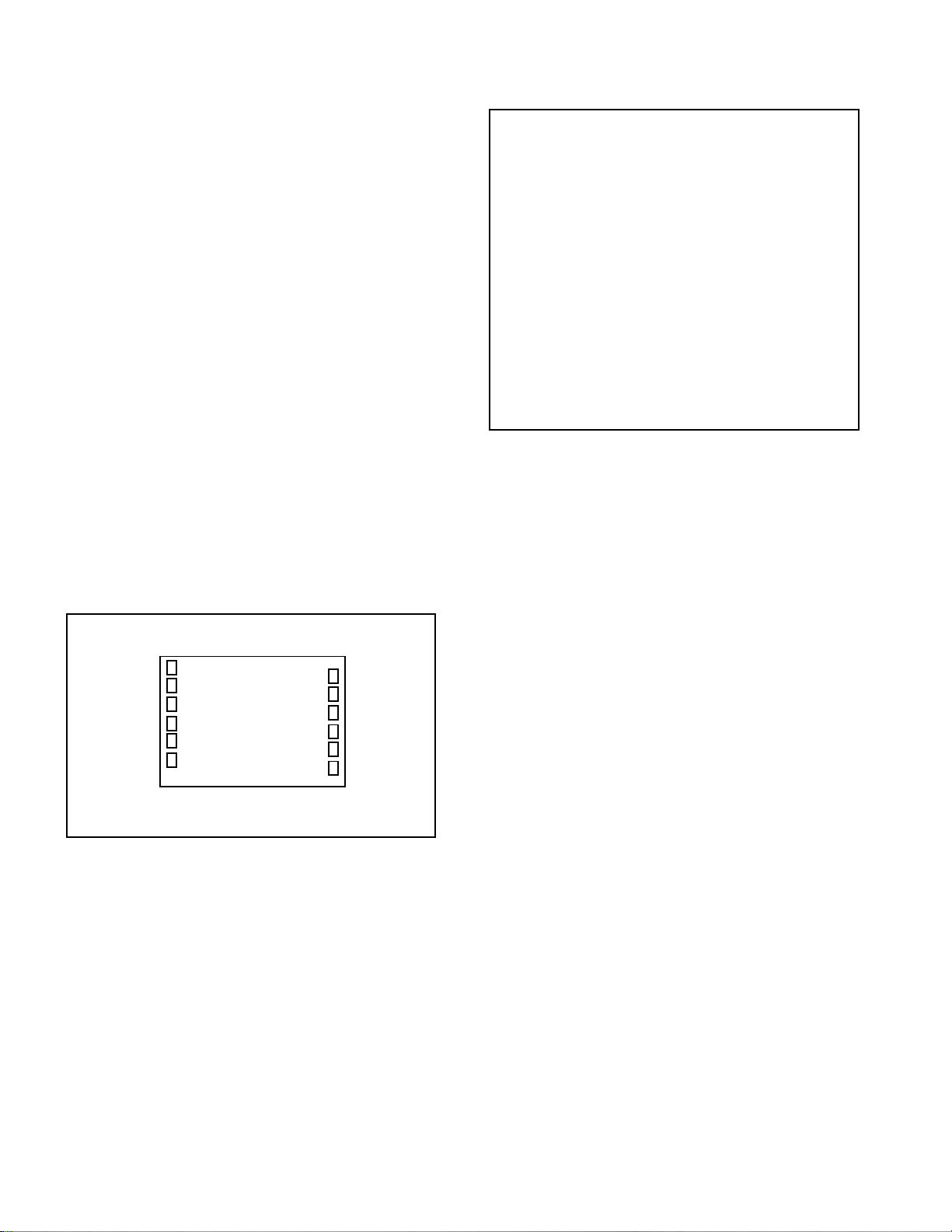
4. BE CAREFUL WITH THE PDP PANEL
1.
When you handle the PDP Filter you must
wear the gloves twice, because, you are to
avoid soil it by your sweat and dust.
2.
When you lift the PDP Filter you should hold it
with the palm of your hand.
Don’t pick up it with your fingers.
3.
The back side of PDP Filter tends to damaged.
Since there is no coating.
Therefore, it put into the packing box at the
time of delivery, without piling up even at the
time of unused.
Also, when you take out it from a packing box,
be careful of the rubbing.
4.
When the surface becomes dirty, wipe it with a
soft cloth as you draw a circle.
When it is dirty hardly, wipe it with a cloth
ethanol infiltrated.
Don’t use ethanol for the back side.
5.
Do not apply it to direct sunshine so that the
characteristic may change.
6.
When you inspect the surface (the scratch, the
dirt and the air bubble), use the fluorescent
light.
7.
When you use SCREW DRIVER and SCREW,
be careful of a metallic powder being mixed.
8.
Do not damage the PDP Module with a
DRIVER.
9.
Do Handling with the PDP Module by 2
persons.
10.
There is a step difference between the cover
and PDP Module.
So, when you remove the screws, place a
cushion on it so that the PDP Module is not
being scratched.
Then remove the screws carefully.
PERFORM A SAFETY CHECK AFTER
6.
SERVICING
Confirm that the screws, parts and wiring which
were removed in order to service are put in the
original positions, or whether there are the
portions which are deteriorated around the
serviced places serviced or not. Check the
insulation between the antenna terminal or
external metal and the AC cord plug blades.
And be sure the safety of that.
(INSULATION CHECK PROCEDURE)
Unplug the plug from the AC outlet.
1.
Remove the antenna terminal on TV and turn
2.
on the TV.
Insulation resistance between the cord plug
3.
terminals and the eternal exposure metal
[Note 2] should be more than 2.5M ohm by
using the 500V insulation resistance meter
[Note 1].
If the insulation resistance is less than 2.5M
4.
ohm, the inspection repair should be
required.
[Note 1]
If you have not the 500V insulation
resistance meter, use a Tester.
[Note 2]
External exposure metal: Antenna terminal
Screw
21pin jack
Side RCA jack
Rrar RCA jack
Headphone jack
A1-2

HOW TO ORDER PARTS
Please include the following informations when you order parts. (Particularly the VERSION LETTER.)
1. MODEL NUMBER and VERSION LETTER
The MODEL NUMBER can be found on the back of each product and the VERSION LETTER can be
found at the end of the SERIAL NUMBER.
2. PART NO. and DESCRIPTION
You can find it in your SERVICE MANUAL.
IMPORTANT
When you exchange IC and Transistor with a heat sink, apply silicon grease (YG6260M) on the contact
section of the heat sink. Before applying new silicon grease, remove all the old silicon grease.
(Old grease may cause damage to the IC and Transistor).
PANEL LOCK
To unlock the Password of Panel Lock, please follow the steps below.
Turn Unit ON.
1.
Press and hold the ‘VOLUME DOWN’ key on the front panel for more than 10 seconds.
2.
The Panel Lock has now been cleared.
3.
A1-3

TABLE OF CONTENTS
GREEN PRODUCT PROCUREMENT ........................................................................................
LEAD-FREE SOLDER ................................................................................................................
SERVICING NOTICES ON CHECKING.....................................................................................
HOW TO ORDER PARTS ..........................................................................................................
IMPORTANT ...............................................................................................................................
PANEL LOCK..............................................................................................................................
TABLE OF CONTENTS..............................................................................................................
GENERAL SPECIFICATIONS ...................................................................................................
DISASSEMBLY INSTRUCTIONS
1.EXCHANGE METHOD OF PDP MODULE...........................................................................
2. REMOVAL AND INSTALLATION OF FLAT PACKAGE IC..................................................
SERVICE MODE LIST ................................................................................................................
WHEN REPLACING EEPROM (MEMORY) IC ..........................................................................
RE-WRITE FOR DIGITAL SOFT FIRMWARE...........................................................................
FUNCTION OF PCB ....................................................................................................................
ELECTRICAL ADJUSTMENTS..................................................................................................
TROUBLESHOOTING GUIDE ...................................................................................................
BLOCK DIAGRAM
SCALER/LVDS/MICON/ADC/JACK/AV SWITCH1/REGULATOR.........................................
AV SWITCH2/STEREO/SOUND AMP....................................................................................
TUNER/DIGITAL/POWER.......................................................................................................
INTERFACE.............................................................................................................................
MICON2 ...................................................................................................................................
PRINTED CIRCUIT BOARDS
AV/REMOCON ........................................................................................................................
SCALER...................................................................................................................................
DIGITAL ...................................................................................................................................
OPERATION/SIDE JACK/FILTER ..........................................................................................
SCHEMATIC DIAGRAMS
AV SWITCH2 ...........................................................................................................................
TUNER/OUT JACK..................................................................................................................
AV JACK ..................................................................................................................................
STEREO ..................................................................................................................................
SOUND AMP/HEADPHONE AMP ..........................................................................................
POWER ...................................................................................................................................
AV JACK2 ................................................................................................................................
IR PASS ...................................................................................................................................
TUNER.....................................................................................................................................
MICON .....................................................................................................................................
SCALER...................................................................................................................................
ADC1........................................................................................................................................
ADC2........................................................................................................................................
LVDS........................................................................................................................................
JACK ........................................................................................................................................
AV SWITCH1 ...........................................................................................................................
REGULATOR...........................................................................................................................
INTERFACE_HDMI IC ............................................................................................................
HDMI MICON2.........................................................................................................................
ASIC.........................................................................................................................................
SDRAM ....................................................................................................................................
FLASH .....................................................................................................................................
FRONT END ............................................................................................................................
AV OUT....................................................................................................................................
POWER2 .................................................................................................................................
OPERATION/SIDE JACK/FILTER ..........................................................................................
INTERCONNECTION DIAGRAM ...............................................................................................
WAVEFORMS .............................................................................................................................
MECHANICAL EXPLODED VIEWS...........................................................................................
MECHANICAL REPLACEMENT PARTS LIST .........................................................................
ELECTRICAL REPLACEMENT PARTS LIST...........................................................................
A1-1
A1-1
A1-2
A1-3
A1-3
A1-3
A2-1
A3-1~A3-5
B1-1~B1-8
B2-1, B2-2
C-1
C-2
C-3
C-4
D-1~D-5
E-1~E-7
F-1, F-2
F-3, F-4
F-5, F-6
F-7, F-8
F-9, F-10
G-1~G-4
G-5~G-8
G-9, G-10
G-11, G-12
H-1, H-2
H-3, H-4
H-5, H-6
H-7, H-8
H-9, H-10
H-11, H-12
H-13, H-14
H-15, H-16
H-17, H-18
H-19, H-20
H-21, H-22
H-23, H-24
H-25, H-26
H-27, H-28
H-29, H-30
H-31, H-32
H-33, H-34
H-35, H-36
H-37, H-38
H-39, H-40
H-41, H-42
H-43, H-44
H-45, H-46
H-47, H-48
H-49, H-50
H-51, H-52
H-53, H-54
I-1~I-3
J-1~J-3
K1-1~K1-3
K2-1~K2-8
A2-1
GENERAL SPECIFICATIONS
G-1 TV PDP PDP Size / Visual Size 42.32 inch / 1074.9 mmV
System Number of Pixels(H x V) 1024(H) x 768(V)
G-2 Tuning Broadcasting System Analog
System Digital ATSC(8VSB)/QAM
G-3 Signal Video Signal Input Level 1 V p-p/75 ohm
G-4 Power Power Source AC 120V AC 60Hz
G-5 Regulation Safety UL/CSA
G-6 Temperature Operation +/-0oC ~ +40oC
G-7 Operating Humidity Less than 80% RH
G-8 Clock and Clock
Timer Sleep Timer Max Time 120 Min
Color System NTSC
Speaker 4 Speaker
Main Size 2.2 x 5.0 inch
Tweeter Size 2.0 inch
Sound Output MAX 10W + 10W
Tuner and System 1Tuner
Receive CH Destination USA(W/ CABLE)
Intermediate Digital 44.00MHz
Frequency Analog Picture(FP) 45.75MHz
Preset CH
Stereo/Dual TV Sound US-Stereo
Tuner Sound Muting Yes
RGB Signal Output Level -Audio Signal Input Level -8.0dBm/50k ohm
Power Consumption at AC 360 W at AC 120 V 60 Hz
Protector Power Fuse Yes
On Timer Program Yes
Off Timer Program No
Game Timer Yes
Wake Up Timer No
Timer Back-up (at Power Off Mode) more than -- Min Sec
Position Front
Impedance 4 ohm
Impedance 8 ohm
10%(Typical) ---
US System
M
CH Coverage 2 - 69, 4A, A-5 - A-1,
A - I, J - W, W+1 - W+84
Sound(FS) 41.25MHz
FP-FS 4.50MHz
No
Output Level 1 V p-p/75 ohm
S/N Ratio (Weighted) -Horizontal Resolution at DVD Mode --
--
Output Level at DVD --
at TV -8 dBm/1k ohm (0dBm=0.775Vrms)
0-600mV /1k ohm (Variable out mode)
Digital Output Level 0.5 V p-p/75 ohm
S/N Ratio at DVD (Weighted) -Harmonic Distortion 0.02% (1KHz)
Frequency Response : at DVD --
at Video CD --
at SVCD --
at CD --
DC ---
at DC -Stand by (at AC) 1 W at AC 120 V 60 Hz
Per Year -- kWh/Year
Energy Star Yes
Safety Circuit Yes
IC Protector(Micro Fuse) No
Radiation FCC/IC
X-Radiation ---
Storage -20oC ~ +60oC
Yes
Step 10 Min
A3-1
GENERAL SPECIFICATIONS
G-9 Remote Unit RC-KK
Control Glow in Dark Remocon Yes
Remocon Format TOSHIBA
Format TOSHIBA
Custom Code
Power Source Voltage(D.C) 3V
Total Keys 44
Keys
Multi Brand Keys
UM size x pcs UM-4 x 2 pcs
Power
Input
Display
Mute
1
2
3
4
5
6
7
8
9
0
100 / +10
CH Return / Ent
CH +
CH VOL +
VOL SLEEP
Picture Size
UP
LEFT / FAV MENU/ENTER/DVD MENU
RIGHT / FAV +
DOWN
EXIT
TV
CBL/SAT
VCR
DVD
ENTER
PAUSE
PLAY
STOP
REW
FF
SKIP/SEARCH|<<
SKIP/SEARCH>>|
TOP MENU
REC
CLEAR
TV/VCR
40-BF h
Yes
Yes
Yes
Yes
Yes
Yes
Yes
Yes
Yes
Yes
Yes
Yes
Yes
Yes
Yes
Yes
Yes
Yes
Yes
Yes
Yes
Yes
Yes
Yes
Yes
Yes
Yes
Yes
Yes
Yes
Yes
Yes
Yes
Yes
Yes
Yes
Yes
Yes
Yes
Yes
Yes
Yes
Yes
Yes
A3-2
GENERAL SPECIFICATIONS
English
G-10 Features Auto Shut Off Yes
Power On Memory Yes
Auto Search No
DNR Yes
Comb Filter Yes
Just Clock Function No
Game Position No
Auto Setup(Language/CH Program) Yes
Picture Setting(TV) Yes
Mode(Picture Preference) Yes
Brightness , Contrast , Color Yes
Tint Yes
Sharpness Yes
Color Temperature Yes
Cable Clear Yes
Picture Setting(PC) Yes
BRIGHTNESS , CONTRAST Yes
HOR POSITION , VER POSITION Yes
PHASE , CLOCK Yes
AUTO ADJUST No
RED , GREEN , BLUE Yes
Audio MTS Yes
Tone Control (Bass/Treble/Balance) Yes
Stable Sound Yes
Surround No
BBE No
SRS WOW (SRS 3D/Focus/Tru Bass) Yes
Valiable Audio Out Yes
Tuning CH Program Yes
TV/Cable Yes
ADD/ERASE Yes
Screen Saver Inversion(Reverse) Yes
Full White(White) Yes
Screen Saver(Picture Shift) Yes
Side Panel Color Yes
Label CH Label Yes
Video Label Yes
Favorite CH Yes
V-Chip
RRT Setup
Lock Hotel Lock No
Channel Lock Yes
Video Lock Yes
Panel Lock Yes
OSD Language
Closed Caption
CC Advanced
Picture Size Yes
Picture Scroll Yes
Aspect Yes
Backlight No
PFC(Power Factor circuit) Yes
Freeze frame No
PIP/POP No
Digital Out Dolby Digital Yes
MPEG No
PCM Yes
DTS No
PC Monitor Input Yes
VGA (640x480) Yes (60Hz)
VGA (720x400) No
WVGA (848x480) Yes (60Hz)
SVGA (800x600) Yes (60Hz)
XGA (1024x768) Yes (60Hz)
WXGA (1280x768) Yes (60Hz)
WXGA (1280x720) Yes (60Hz)
WXGA (1360x768) Yes (60Hz)
SXGA (1280x1024) No
3D
3D
Yes
Yes
Yes
No
A3-3
GENERAL SPECIFICATIONS
HDMIIn put Yes
Component Input Yes
G-11 Accessories Owner's Manual Language English / French / Spanish
Remote Control Unit Yes
Rod Antenna
Loop Antenna (W/ Antenna Change Plug)
U/V Mixer
DC Car Cord (Center+)
Guarantee Card
Warning Sheet
Circuit Diagram
Antenna Change Plug
Service Facility List
Important Safeguard
Dew/AHC Caution Sheet
Quick Set-up Sheet
Battery Yes
AC Adapter
AC Cord (for AC Adapter)
AC Cord Yes
AV Cord (2Pin-1Pin)
HDMI-DVI Cable
Registration Card Yes
300 ohm to 75 ohm Antenna Adapter
Information Sheet Yes
Information Sheet(for IMPORTANT NOTICE) Yes
Information Sheet(for PICTURE SHIFT) Yes
VGA (640×480) Yes (60Hz)
720x480i (4:3) Yes (60Hz)
720x480i (16:9) Yes (60Hz)
720x480p (4:3) Yes (60Hz)
720x480p (16:9) Yes (60Hz)
720x576i (4:3) No
720x576i (16:9) No
720x576p (4:3) No
720x576p (16:9) No
1280x720p Yes (60Hz)
1920x1080i Yes (60Hz)
720x480i (4:3) Yes (60Hz)
720x480i (16:9) Yes (60Hz)
720x480p (4:3) Yes (60Hz)
720x480p (16:9) Yes (60Hz)
720x576i (4:3) No
720x576i (16:9) No
720x576p (4:3) No
720x576p (16:9) No
1280x720p Yes (60Hz)
1920x1080i Yes (60Hz)
w/Guarantee Card Yes
No
Poles Terminal -
No
Terminal -
No
No
No
No
No
No
No
No
No
No
UM size x pcs UM-4 x 2 pcs
OEM Brand No
No
No
No
No
No
A3-4
GENERAL SPECIFICATIONS
G-12 Interface Switch Power (Tact) Yes
Indicator Power / Stand-by Yes(GREEN / RED)
Terminals Rear Video Input 1 RCA x 1
Side Video Input 3 RCA x 1
G-13 Set Size Approx. W x D x H (mm) 1,070 x 350 x 779.5
G-14 Weight Net Approx. 38.4kg (84.7 lbs)
G-15 Carton Master Carton
Gift Box Material Double/Brown
Drop Test
Container Stuffing 100
G-16 Material Cabinet Cabinet Front ABS 94V0 Non-DECABROM
PCB Non-Halogen
G-17 Environment Environmental standard requirement Green procurement of TOSHIBA
Pb-free Phase3(Pha
System Select No
Main Power SW No
Channel Up/Menu Up Yes
Channel Down/Menu Down Yes
Volume Up/Menu > Yes
Volume Down/Menu < Yes
Input Select Yes
Menu No
Main Power SW No
On Timer No
Audio Input
S- Input
Video Input 2 RCA x 1
Audio Input
S- Input
Video Output RCA x 1
Audio Output RCA x 2(Variable L, R)
Component In 1
Audio Input (Component In use)
Component In 2
Audio Input (Component In use)
Other Terminal No
Euro Scart (21Pin) No
PC Monitor Input (D-Sub)
Audio Input
HDMI Input 1
Audio Input(DVI 1) PC Monitor Audio Input Alternative
HDMI Input 2
Audio Input(DVI 2)
Sub Woofer Out No
Diversity No
Digital Audio Out (Coaxial)
Digital Audio Out (Optical)
IR Pass Through
Ext Speaker No
DC Jack 12V(Center +) No
VHF/UHF Antenna Input(Digital/Analog)
AC Inlet
Audio Input RCA x2(L/MONO,R)
S- Input
Other Terminal No
Gross Approx. 45.4kg (100.1 lbs)
Content --- Sets
Material --- / --Dimensions W x D x H(mm) --Description of Origin ---
Dimensions W x D x H(mm) 1,180 x 440 x 895
Design As per Buyer's
Description of Origin Yes
Height (cm) 50(ORION SPEC:31)
Cabinet Rear Steel
Eyelet Yes
RCA x 2(L/MONO, R)
Yes
RCA x 2(L/MONO, R)
Yes
RCA x 3
RCA x 2(L/MONO, R)
RCA x 3
RCA x 2(L/MONO, R)
Yes
RCA x 2(L/MONO, R)
Yes
Yes
Mini Pin Jack(3.5), STEREO
Yes
Yes
Yes
F Type
Yes
Yes
No
Natural Dropping At 1 Corner / 2 Edges /
4 Surfaces
Sets/40' container
No
A3-5
DISASSEMBLY INSTRUCTIONS
1. EXCHANGE METHOD OF PDP MODULE
NOTE
1.
Do handling with the PDP Module by 2 persons.
REMOVAL METHOD OF PDP MODULE
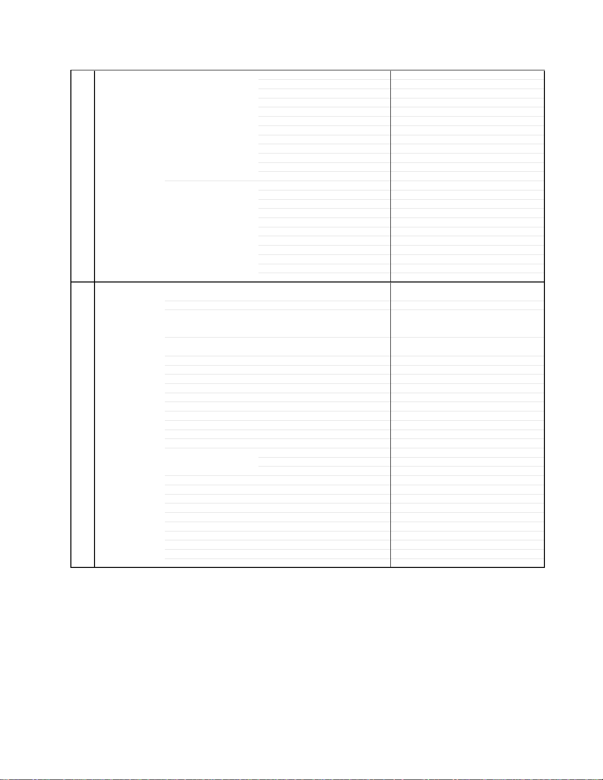
1-1: CABINET BACK/COVER BACK
1.
Remove the screw.
2.
Remove the Cabinet Back and Cover Back.
Cabinet Back
Cover Back
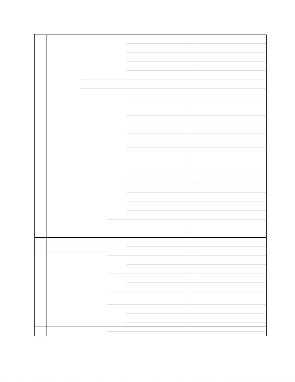
1-2: STAND ASS'Y
Spread a sheet on the plane table and place the PDP Module carefully with the panel face down.
1.
2.
Remove the screw.
Remove the Stand Ass'y.
3.
Stand Ass'y
B1-1
DISASSEMBLY INSTRUCTIONS
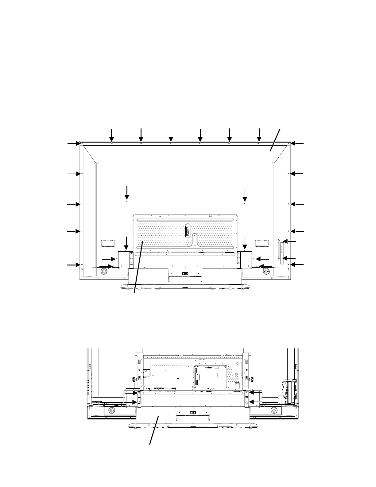
1-3: CHASSIS BLOCK
Disconnect the connector.
1.
2.
Remove the screw.
Remove the Chassis Ass'y.
3.
Chassis Ass'y
1-4: PDP MODULE
Remove the screw.
1.
Remove the Side Jack.
2.
3.
Hold the Frame Main carefully and remove the PDP Module.
NOTE
1.
When removing the PDP Module, raise the cushion carefully so that you do not scratch the face.
Frame Main
Raise the cushion.
PDP Module
Frame Main
B1-2
Side Jack
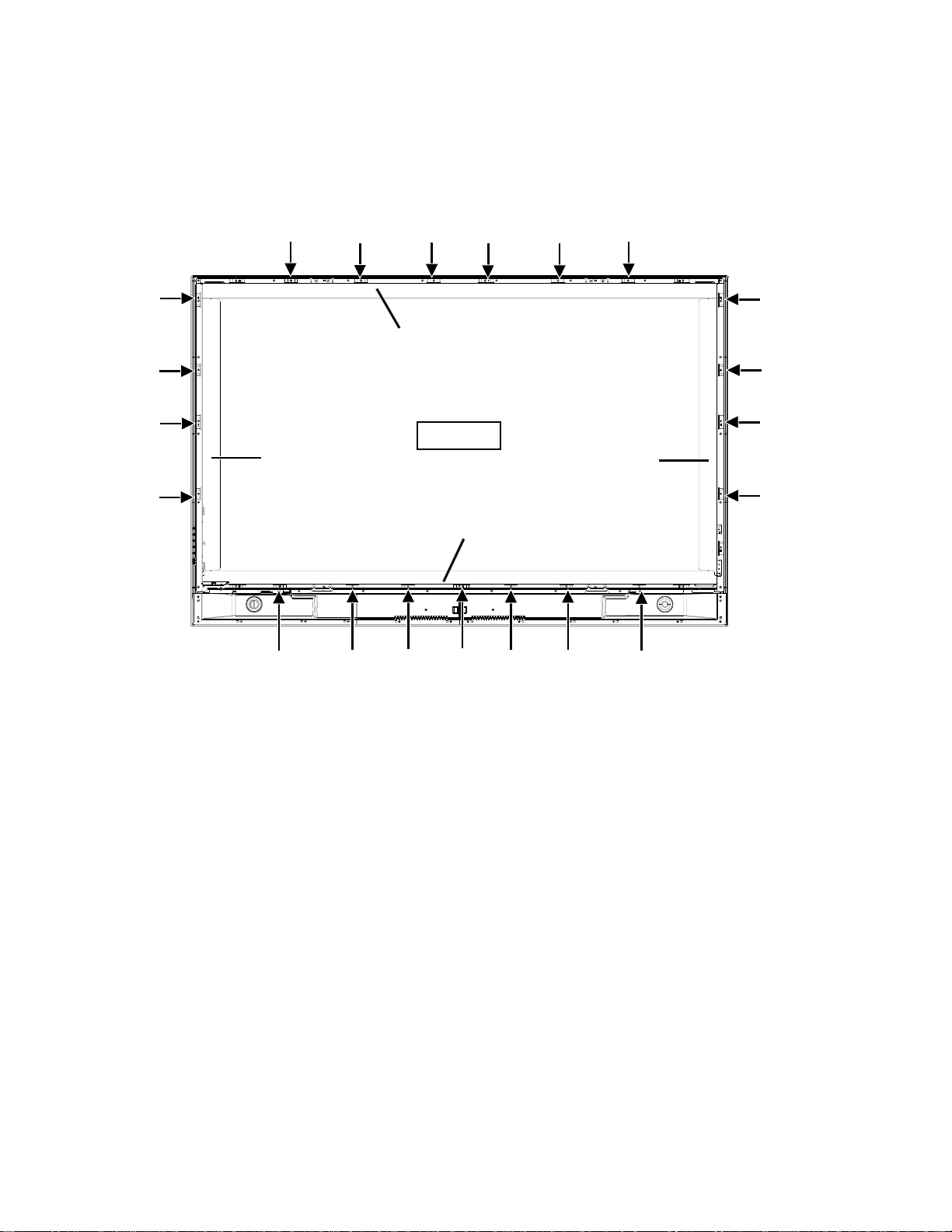
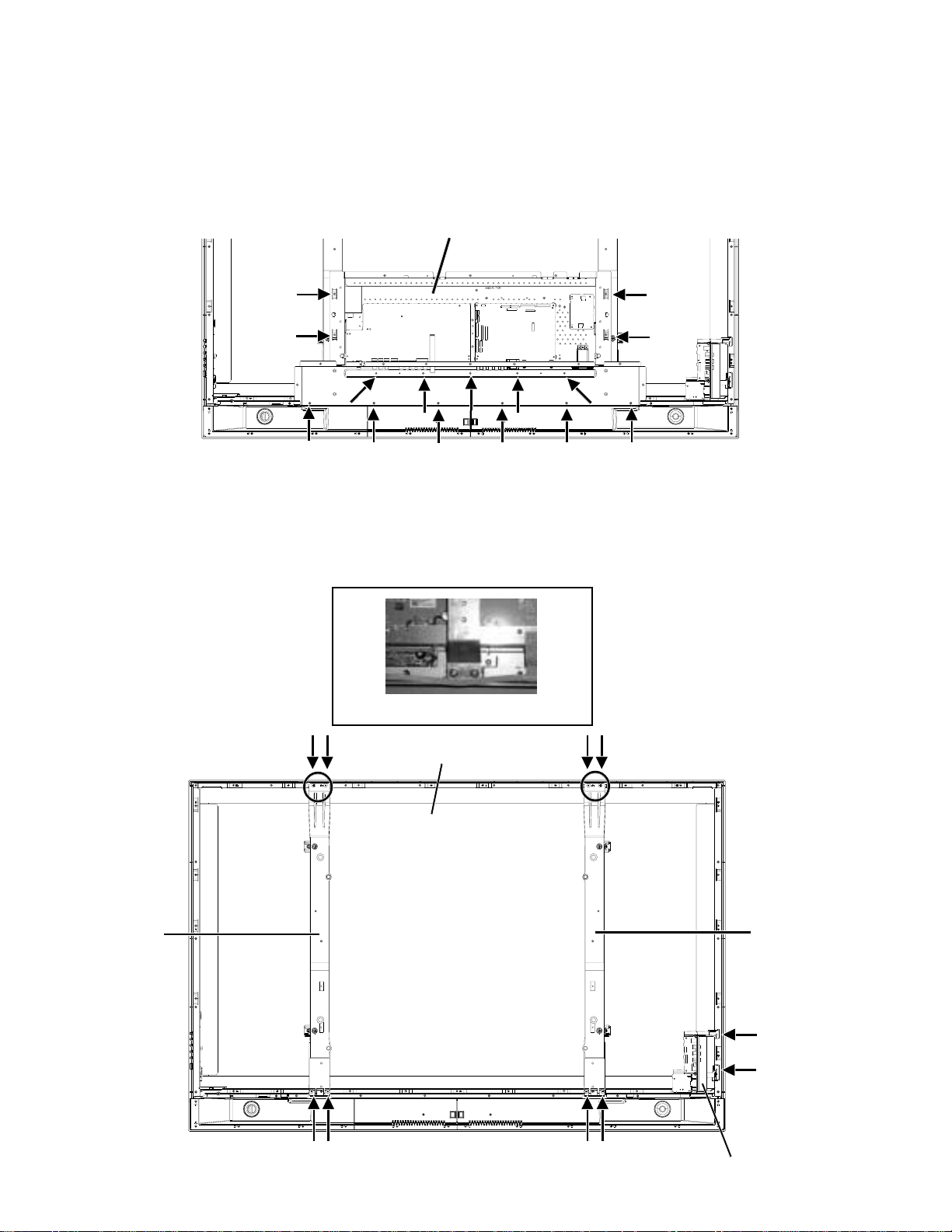
1-5: PDP FILTER
1.
Remove the screw.
Remove the Shield Main.
2.
3.
Remove the PDP Filter.
DISASSEMBLY INSTRUCTIONS
Shield Main L
Shield Main Top
PDP Filter
Shield Main R
Shield Main Bottom
B1-3
DISASSEMBLY INSTRUCTIONS
12345678901234567890123456789012123456789012345678
12345678901234567890123456789012123456789012345678
12
12
12
12
12
12
12
12
12
12
12
12
12
12
12
12
12
12
12
12
12
12
12
12
12
12
12
12
12
12
4
4
4
4
4
4
4
4
4
4
4
4
4
4
4
4
4
4
4
4
4
4
4
4
4
4
4
4
4
4
4
5
5
INSTALLATION METHOD OF PDP MODULE
NOTES FOR NEW PDP FILTER HANDLING
1.
When you handle the PDP Filter, you must wear gloves to avoid soiling it with sweat and dust.
2.
When you lift the PDP Filter, use the palm of your hand. Don’t pick it up with your fingers.
3.
The back side of the PDP Filter tends to get damaged, since there is no coating. Therefore, it needs to be put into the
packing box at the time of delivery, even if it is not being used at the time. Also, when you take it out of the packing box, be
careful not to rub the appearance.
4.
When the surface becomes dirty, use a cloth which is soft and dust free and wipe it in a circular motion.
When very dirty, lightly use alcohol on the cloth to wipe. Do not use alcohol for the back side.
5.
Do not apply it to direct sunlight, the characteristics may change.
6.
When you inspect for scratches and dirt, use a light to check for air bubbles on the PDP Filter surface.
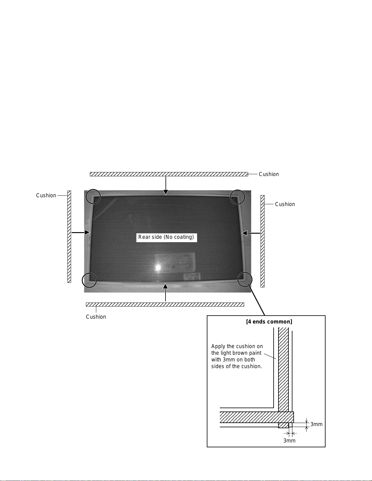
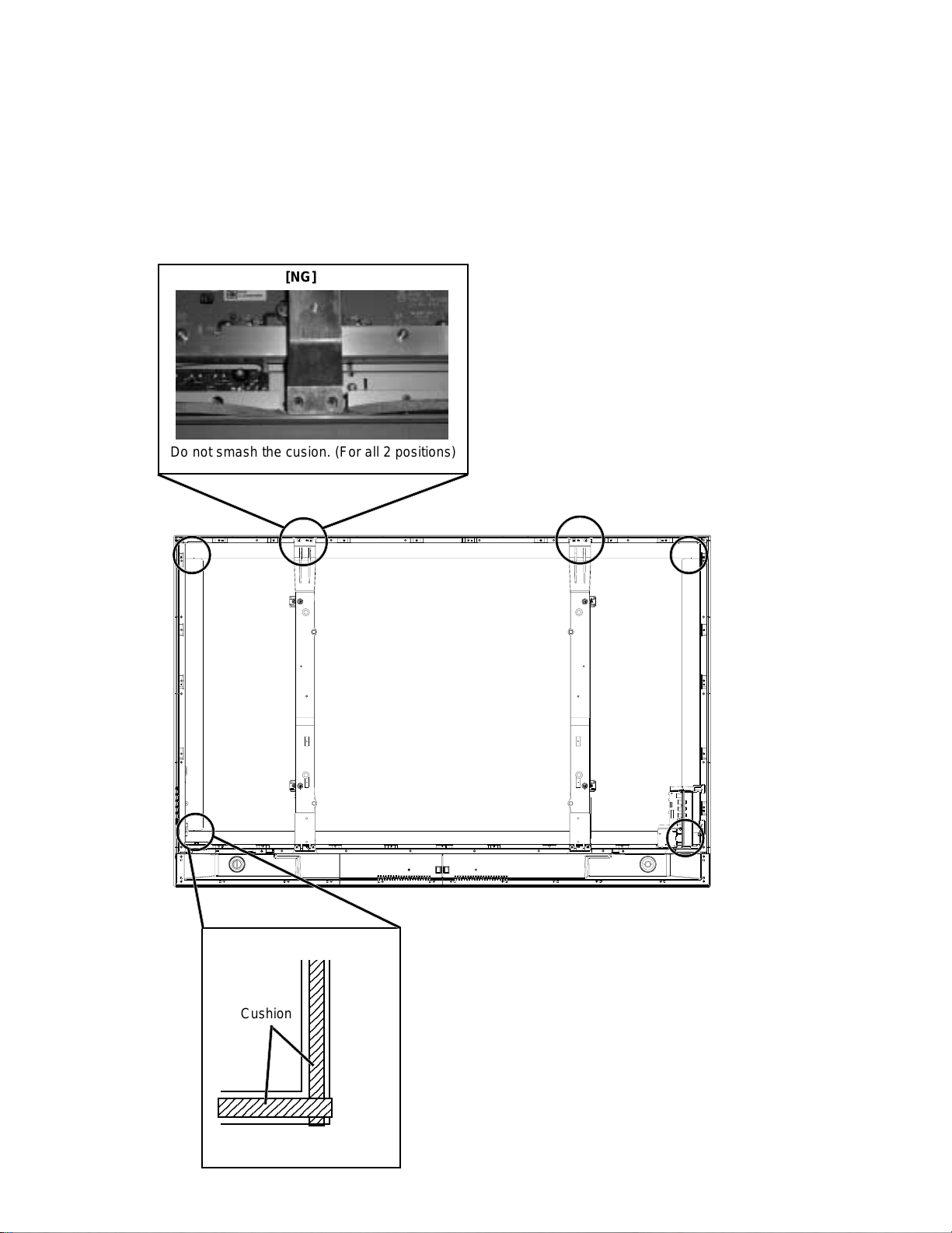
1-6: PDP FILTER (PREPARATION)
Fix the cushion. (Order the cushion new.)1.
Cushion
Cushion
Cushion
Rear side (No coating)
Cushion
B1-4
[4 ends common]
Apply the cushion on
the light brown paint
with 3mm on both
sides of the cushion.
23456789012345678901234
23456789012345678901234
23
23
23
23
23
23
23
23
23
23
23
23
23
23
23
23
23
23
23
23
23
23
23
23
23
23
23
23
23
23
23
3mm
3mm
DISASSEMBLY INSTRUCTIONS
NOTES FOR NEW PDP MODULE HANDLING
Handle the PDP Module with 2 people.
1.
There is a step difference between the cover and the PDP Module, so when you remove the screws, place a cushion on it
2.
to keep the PDP Module from being scratched. Then remove the screws carefully.
When you remove the cover, do not scratch the FPC on both ends of PDP Module.
3.
Hold all four ends of the holder and be careful not to touch the glass area.
4.
Be careful not to damage the vacuum exhaust pipe.
5.
Moisture condensation may damage the PDP Module, so leave it in the service room for 48 hours.
6.
Reuse the cover, vinyl sheet and screws when returning the PDP Module.
7.
Vacuum Exhaust Pipe
FPC
B1-5
DISASSEMBLY INSTRUCTIONS
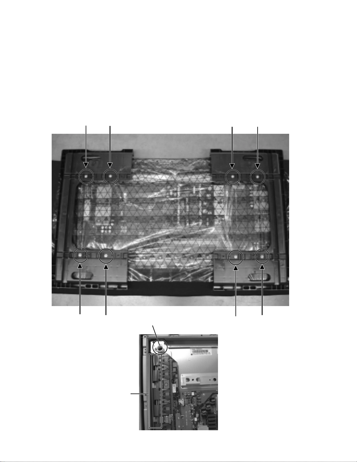
1-7: PDP MODULE (PREPARATION)
Remove the fixing screw of Power PCB. Then fix the Wiring Clip. (Use the clips on defective PDP Module)
1.
Fix the Cord Clip. (Use the clips on defective PDP Module)
2.
Fix the Wiring Clip. (Use the clips on defective PDP Module)
3.
Wiring Clip
Set SW501 (24V)
Cord Clip
45˚
Cord Clip
B1-6
DISASSEMBLY INSTRUCTIONS
3
3
3
3
3
3
3
3
3
3
3
3
3
3
3
3
3
3
3
3
5
1-8: PDP MODULE
Assemble the Frame Main. (Use the clips on defective PDP Module)
1.
Install the PDP Filter on the set.
2.
Install the Shield Main on the set.
3.
Hold the Frame Main carefully and install the New PDP Module on the set.
4.
Install the Side Jack on the set.
5.
[NG]
Do not smash the cusion. (For all 2 positions)
[4 ends common]
Cushion
2345678901234
Pile up the cushion.
2
2
2
2
2
2
2
2
2
2
2
2
2
2
2
2
2
2
2
2
B1-7
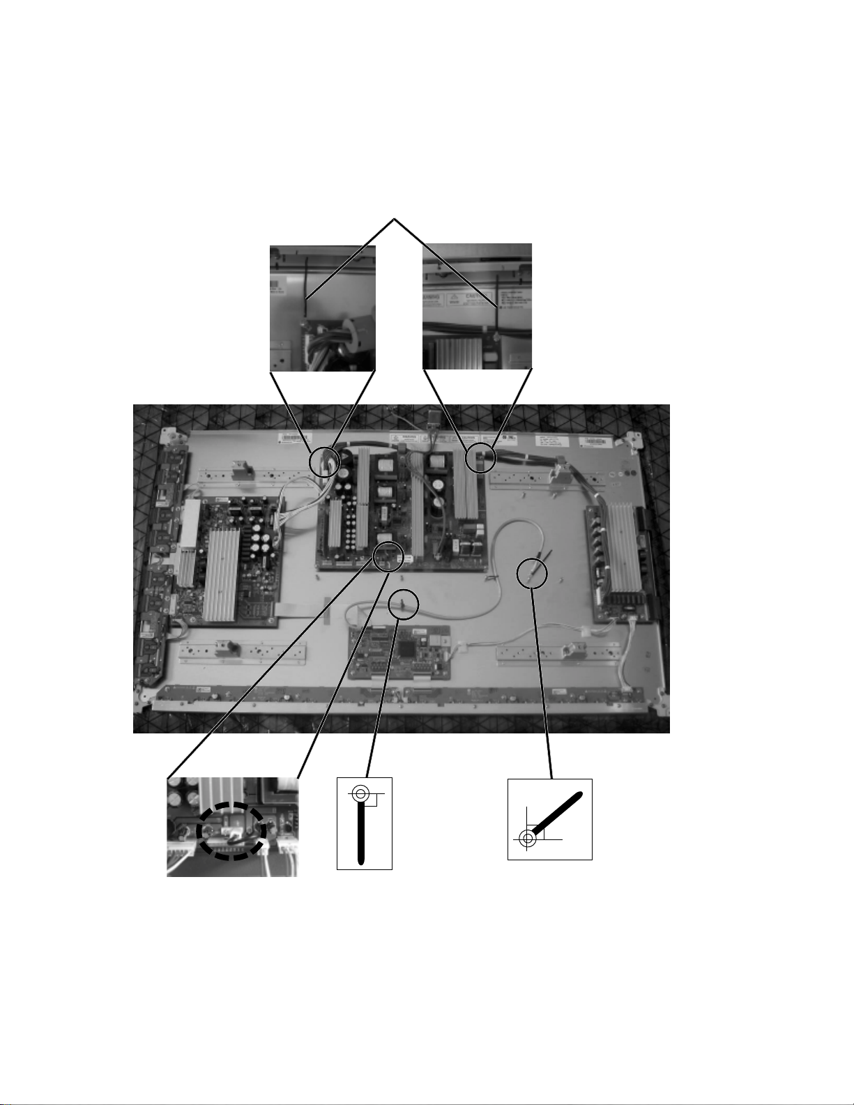
DISASSEMBLY INSTRUCTIONS
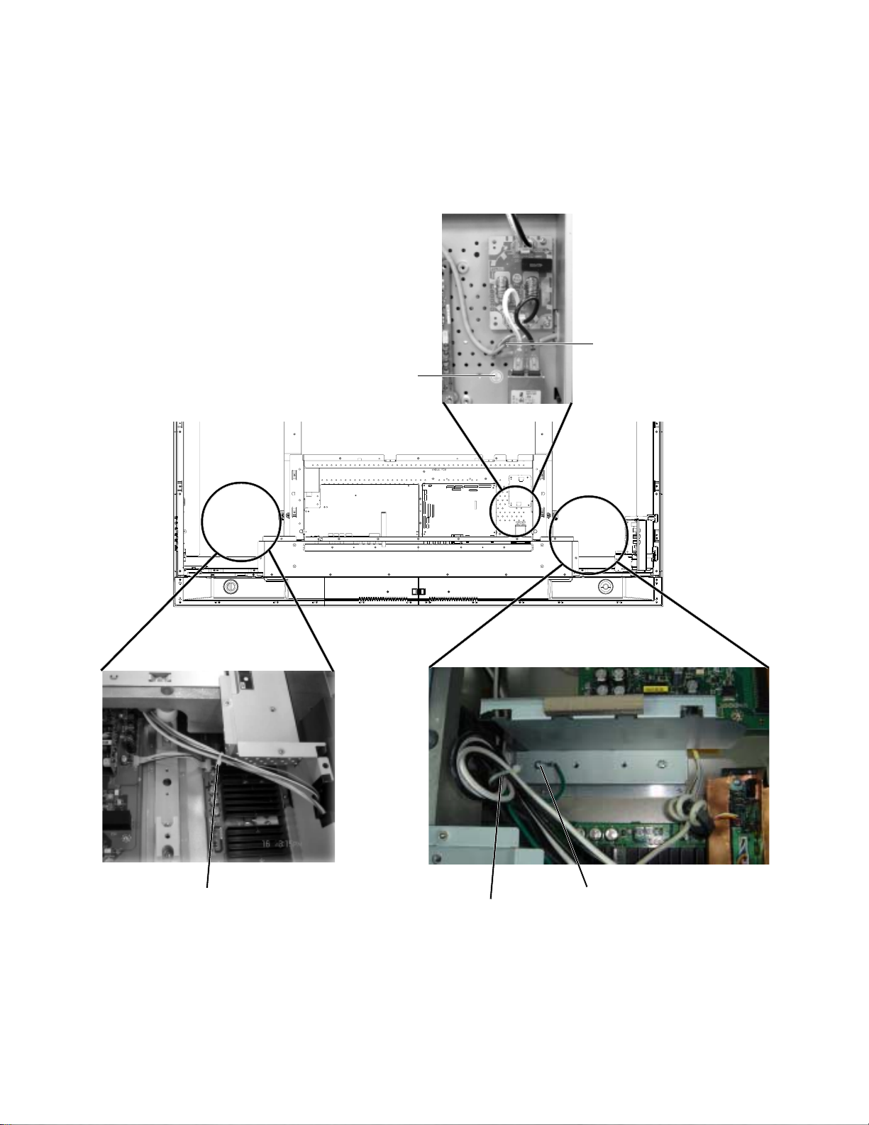
1-9: CHASSIS BLOCK
Do the wire fixing as shown in the photo, then install the Chassis Ass'y.
1.
Install the Stand Ass'y.
2.
Sheet Earth Mark
Earth wire of AC Inlet.
Band Cord Clamp
1-10: CABINET BACK/COVER BACK
1.
Check if the wire handlings are correct.
2.
Check if the cushion positions are correct.
3.
Check if the tape positions are correct.
4.
Install the Cabinet Back and Cover Back.
Band Cord Clamp
Earth wire
B1-8
DISASSEMBLY INSTRUCTIONS
2.
REMOVAL AND INSTALLATION OF
FLAT PACKAGE IC
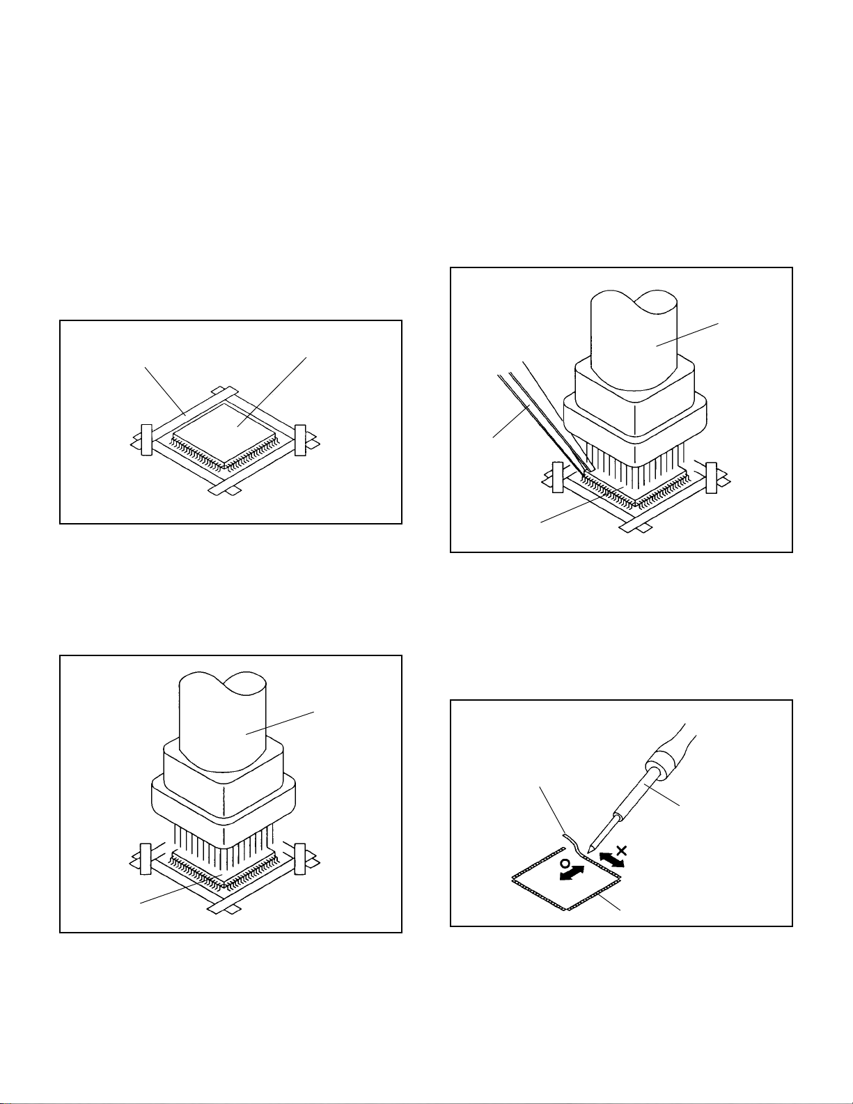
REMOVAL
Put Masking Tape (cotton tape) around the Flat Package
1.
IC to protect other parts from any damage.
(Refer to Fig. 2-1.)
NOTE
Masking is carried out on all the parts located within 10
mm distance from IC leads.
When IC starts moving back and forth easily after
3.
desoldering completely, pickup the corner of the IC using a
tweezers and remove the IC by moving with the IC
desoldering machine. (Refer to Fig. 2-3.)
NOTE
Some ICs on the PCB are affixed with glue, so be
careful not to break or damage the foil of each IC leads
or solder lands under the IC when removing it.
Blower type IC
desoldering
machine
Masking Tape
(Cotton Tape)
Heat the IC leads using a blower type IC desoldering
2.
IC
machine. (Refer to Fig. 2-2.)
NOTE
Do not rotate or move the IC back and forth , until IC
can move back and forth easily after desoldering the
leads completely.
Blower type IC
desoldering machine
Fig. 2-1
Tweezers
IC
Peel off the Masking Tape.4.
Absorb the solder left on the pattern using the Braided
5.
Shield Wire. (Refer to Fig. 2-4.)
NOTE
Do not move the Braided Shield Wire in the vertical
direction towards the IC pattern.
Fig. 2-3
Braided Shield Wire
Soldering Iron
IC
Fig. 2-2
IC pattern
Fig. 2-4
B2-1
DISASSEMBLY INSTRUCTIONS
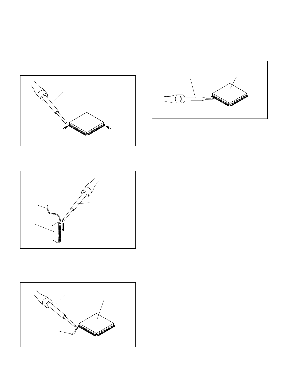
INSTALLATION
Take care of the polarity of new IC and then install the new
1.
IC fitting on the printed circuit pattern. Then solder each
lead on the diagonal positions of IC temporarily.
(Refer to Fig. 2-5.)
Soldering Iron
Solder temporarily
Supply the solder from the upper position of IC leads
2.
sliding to the lower position of the IC leads.
(Refer to Fig. 2-6.)
Solder temporarily
Fig. 2-5
When bridge-soldering between terminals and/or the
4.
soldering amount are not enough, resolder using a Thin-tip
Soldering Iron. (Refer to Fig. 2-8.)
Thin-tip Soldering Iron
IC
Fig. 2-8
Finally, confirm the soldering status on four sides of the IC
5.
using a magnifying glass.
Confirm that no abnormality is found on the soldering
position and installation position of the parts around the IC.
If some abnormality is found, correct by resoldering.
NOTE
When the IC leads are bent during soldering and/or
repairing, do not repair the bending of leads. If the
bending of leads are repaired, the pattern may be
damaged. So, always be sure to replace the IC in this
case.
Soldering IronSolder
IC
Supply soldering
from upper position
to lower position
Fig. 2-6
Absorb the solder left on the lead using the Braided Shield
3.
Wire. (Refer to Fig. 2-7.)
NOTE
Do not absorb the solder to excess.
Soldering Iron
IC
Braided Shield Wire
Fig. 2-7
B2-2
SERVICE MODE LIST
This unit is provided with the following SERVICE MODES so you can repair, examine and adjust easily.
To enter to the SERVICE MODE function, press and hold both buttons simultaneously on the main unit and on the remote
control for more than the standard time in the appropriate condition. (See below chart.)
Set
Condition
TV mode
TV mode
TV mode
ALL mode
ALL mode
Set Key Operations
VOL. DOWN
(Minimum)
VOL. DOWN
(Minimum)
VOL. DOWN
(Minimum)
VOL. DOWN
(Minimum)
VOL. DOWN
(Minimum)
Remocon
Key
0 2 sec.
1 2 sec.
6 2 sec.
8
9 2 sec.
Standard
Time
2 sec.
Releasing of V-CHIP PASSWORD.
Initialization of factory TV data.
NOTE:
Can be checked of the INITIAL DATA of MEMORY IC.
Refer to the "WHEN REPLACING EEPROM (MEMORY) IC".
Check of the SUM DATA, POWER ON total hours, MICON
VERSION and DIGITAL TV MICON FIRMWARE on the screen.
Refer to the "WHEN REPLACING EEPROM (MEMORY) IC".
Display of the Adjustment MENU on the screen.
Refer to the "ELECTRICAL ADJUSTMENT" (On-Screen Display
Adjustment).
If you set factory initialization, the memories are reset
such as the channel setting, and the POWER ON total
hours.
C-1
WHEN REPLACING EEPROM (MEMORY) IC
CONFIRMATION OF CHECK SUM, POWER ON TOTAL HOURS, MICON VERSION AND
DIGITAL TV MICON FIRMWARE
Initial total of MEMORY IC, POWER ON total hours, MICON VERSION and Digital TV MICON Firmware can be checked on
the screen. Total hours are displayed in 16 system of notation.
NOTE:
1.
2.
3.
4.
If you set a factory initialization, the total hours is reset to "0".
Please refer to "CONFIRMATION OF INITIAL DATA" when SUM DATA is not corresponding.
Turn on the POWER, and set to the TV mode.
Set the VOLUME to minimum.
Press both VOL. DOWN button on the set and Channel
button (8) on the remote control for more than 2 seconds.
After the confirmation of each check sum, POWER ON
total hours, MICON VERSION and Digital TV MICON
Firmware, turn off the power.
*1 DVP1 is different according to each set.
MICON Version
INIT : 6082
VOLUME : 2E25
ROM : 0000
ADC : BFDE
DVP1 : EE40 *1
DVP2 : D172
PICENH : 5626
PDP ON :0001
OEC7147A_079
Initial setting data check sum.
VOLUME CURVE data check sum.
Rom correction data check sum.
AD CONVERTER data check sum.
SCALER data check sum.
DV1000 data check sum.
POWER ON total hours.
= (16 x 16 x 16 x thousands digit value)
+ (16 x 16 x hundreds digit value)
+ (16 x tens digit value)
+ (ones digit value)
CONFIRMATION OF INITIAL DATA
If a service repair is undertaken where it has been required to change the MEMORY IC, the following steps should be taken to
ensure correct data settings while making reference to INITIAL SETTING TABLE (Attached "INITIAL DATA").
Turn on the POWER, and set to the TV mode.
1.
Set the VOLUME to minimum.
2.
Press both VOL. DOWN button on the set and Channel button (6) on the remote control for more than 2 seconds.
3.
ADDRESS and DATA should appear as FIG 2.
ADDRESS DATA
INIT 0000 B4
PDP ON 0001
OEC7147A_079
DTV d-l62155
INIT :0000
ROM : 0000
VOLUME : 2E25
FIG. 2
ADDRESS is now selected and should "blink". Using the UP/DOWN buton on the remote, step through the ADDRESS
4.
until required ADDRESS to be changed is reached.
Press RIGHT/LEFT button to select DATA. When DATA is selected, it will "blink".
5.
Again, step through the DATA using UP/DOWN button until required DATA value has been selected.
6.
Pressing RIGHT/LEFT button will take you back to ADDRESS for further selection if necessary.
7.
Repeat steps 4 to 6 until all data has been checked.
8.
When satisfied correct DATA has been entered, turn POWER off (return to STANDBY MODE) to finish DATA input.
9.
After the data input, set to the initializing of shipping.
Turn POWER on.
10.
Press both VOL. DOWN button on the set and Channel button (1) on the remote control for more than 2 seconds.
11.
After the finishing of the initializing of shipping, the unit will turn off automatically.
12.
The unit will now have the correct DATA for the new MEMORY IC.
C-2
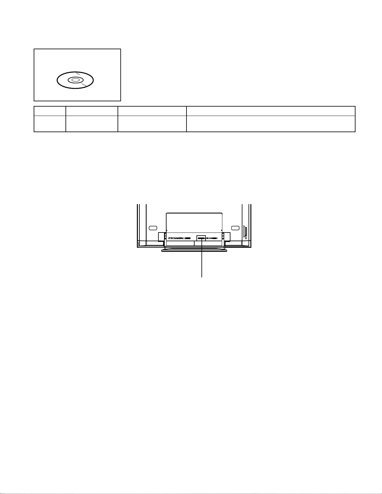
RE-WRITE FOR DIGITAL SOFT FIRMWARE
JG176
Ref. No.
JG176
NOTE:
Prepare the following tools for Up-Date of the Firmware.
1 Computer of WINDOWS2000
2 USB Flash Memory (Use only SanDisk Cruzer Mini USB Flash Drive 256Mb)
USA HD DTV ROM
DISC
Part No. Parts Name
APJG176095
The operating manual for Re-writing is included in USA HD DTV ROM DISC (JG176).
USA HD DTV ROM
DISC
Up-Date of the Firmware
SET (REAR)
Remarks
USB CONNECTOR
C-3
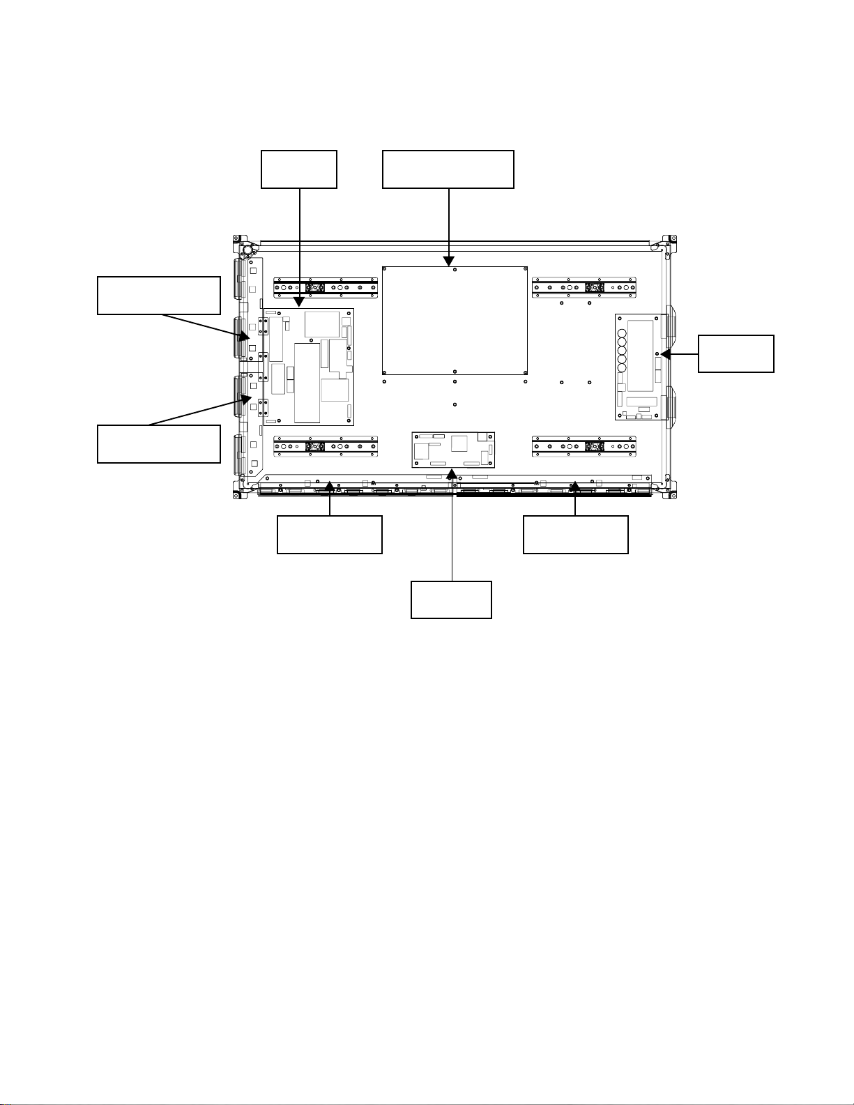
FUNCTION OF PCB
TDRV TOP
YDRV BOT
Y SUS
XRLT
42 SANKEN PSU
POWER
Z SUS
XRRT
42 SANKEN PSU :
Y SUS :
Z SUS :
CTRL :
XRLT :
XRRT :
TDRV TOP :
TDRV BOT :
CTRL
A supplier which supplies voltage and current to each PCB and Panel.
According to the timing provided from Panel Control, switches FETs and
generates driving waveform signal which is provided to Y electrode through
Scan Driver IC of TDRV TOP and TDRV BOT.
According to the timing provided from Panel Control, switches FETs and
generates driving waveform signal which is provided to Z electrode through
Connector.
Controls Y electrode, Z electrode, and ADDRESS electrode.
Generates Address electrode and supplies to Address electrode by Driver IC.
Generates Address electrode and supplies to Address electrode by Driver IC.
Generates Scan electrode and supplies to Y electrode by Driver IC.
Generates Scan electrode and supplies to Y electrode by Driver IC.
C-4
ELECTRICAL ADJUSTMENTS
1. ADJUSTMENT PROCEDURE
Read and perform these adjustments when repairing the
circuits or replacing electrical parts or PCB assemblies.
CAUTION
•
Use an isolation transformer when performing any
service on this chassis.
•
When removing a PCB or related component, after
unfastening or changing a wire, be sure to put the wire
back in its original position.
•
When you exchange IC and Transistor with a heat sink,
apply silicon grease (YG6260M) on the contact section of
the heat sink. Before applying new silicon grease,
remove all the old silicon grease. (Old grease may cause
damage to the IC and Transistor).
Prepare the following measurement tools for electrical
adjustments.
1. Pattern Generator
2. BASIC ADJUSTMENTS
On-Screen Display Adjustment
1.2.Set the VOLUME to minimum.
Press the VOL. DOWN button on the set and the
channel button (9) on the remote control for more than
2 seconds to display adjustment mode on the screen as
shown in Fig. 2-1.
TV
AUTO
01 H POSI OSD
3.
Use the Channel UP/DOWN button or Channel button
(0-9) on the remote control to select the options shown
in Fig. 2-2.
4.
Press the MENU button on the remote control to end
the adjustments.
5.
To display the adjustment screen for AV, YUV, HDMI
and PC mode, press the INPUT button on the remote
control to set to the AV, YUV, HDMI and PC mode.
Press the VOL.DOWN button on the set and the
channel (9) on the remote control for more than 2
seconds.
90
Fig. 2-1
NO.
FUNCTION
NO.
H POSI OSD
01
V POSI OSD
02
R DRIVE (N)
03
R CUT OFF (N)
04
G DRIVE (N)
05
G CUT OFF (N)
06
B DRIVE (N)
07
B CUT OFF (N)
08
R DRIVE (C)
09
R CUT OFF (C)
10
G DRIVE (C)
11
G CUT OFF (C)
12
B DRIVE (C)
13
B CUT OFF (C)
14
R DRIVE (W)
15
R CUT OFF (W)
16
G DRIVE (W)
17
G CUT OFF (W)
18
FUNCTION
19
B DRIVE (W)
20
B CUT OFF (W)
22
H POSI 60Hz
24
V POSI 60Hz
28
BRIGHT CENT
29
BRIGHT MAX
30
BRIGHT MIN
31
TINT
35
CONTRAST CENTER
36
CONTRAST MAX
37
CONTRAST MIN
38
COLOR CENT
39
COLOR MAX
40
COLOR MIN
Fig. 2-2
2-1: CONTRAST MAX
1.
Receive the monoscope pattern. (VIDEO Input)
2.
Press the INPUT button on the remote control to set to the
AV mode.
3.
Activate the adjustment mode display of Fig. 2-1 and press
the channel button (36) on the remote control to select
"CONTRAST MAX".
4.
Press the VOL UP/DOWN button on the remote control
until the contrast step No. becomes "155".
5.
Check if the picture is normal.
6.
Receive the monoscope pattern. (RF Input)
7.
Press the INPUT button on the remote control to set to the
TV mode.
8.
Activate the adjustment mode display of Fig. 2-1 and press
the channel button (36) on the remote control to select
"CONTRAST MAX".
9.
Press the VOL UP/DOWN button on the remote control
until the contrast step No. becomes "145".
10.
Check if the picture is normal.
11.
Receive the digital broadcast. (RF Input)
12.
Perform the above adjustments 3 and 5.
13.
Playback the DVD(480i) disc. (COMPONENT Input)
14.
Press the INPUT button on the remote control to set to the
YUV mode.
15.
Activate the adjustment mode display of Fig. 2-1 and press
the channel button (36) on the remote control to select
"CONTRAST MAX".
16.
Press the VOL UP/DOWN button on the remote control
until the contrast step No. becomes "162".
17.
Check if the picture is normal.
18.
Playback the DVD(480i) disc. (HDMI Input)
19.
Press the INPUT button on the remote control to set to the
HDMI mode.
20.
Activate the adjustment mode display of Fig. 2-1 and press
the channel button (36) on the remote control to select
"CONTRAST MAX".
21.
Press the VOL UP/DOWN button on the remote control
until the contrast step No. becomes "130".
22.
Check if the picture is normal.
D-1

ELECTRICAL ADJUSTMENTS
2-2: WHITE BALANCE
1.
Place the set in Aging Test for more than 15 minutes.
2.
Receive the gray scale pattern from the Pattern
Generator.
3.
Press the INPUT button on the remote control to set to
the AV mode.
4.
Using the remote control, set the brightness and contrast
to normal position.
5.
Activate the adjustment mode display of Fig. 2-1 and
press the channel button (03) on the remote control to
select “R DRIVE (N)”.
6.
Press the CH. UP/DOWN button on the remote control to
select the “R CUTOFF (N)”, “B.DRIVE(N)”, “B CUTOFF
(N)”, “R DRIVE (C)”, “R CUTOFF (C)”, “B.DRIVE(C)”, “B
CUTOFF (C)”, “R DRIVE (W)”, “R CUTOFF (W)”,
“B.DRIVE(W)”and “B CUTOFF (W)”.
7.
Adjust the VOL. UP/DOWN button on the remote control
to whiten the R CUTOFF (N), B.DRIVE(N), B CUTOFF
(N), R DRIVE (C), R CUTOFF (C), B.DRIVE(C), B
CUTOFF (C), R DRIVE (W), R CUTOFF (W),
B.DRIVE(W) and B CUTOFF (W) at each step tone
sections equally.
8.
Perform the above adjustments 6 and 7 until the white
color is looked like a white.
2-3: BRIGHT CENT
1.
Receive the monoscope pattern. (VIDEO Input)
2.
Press the INPUT button on the remote control to set to
the AV mode.
3.
Set the screen mode to FULL.
4.
Using the remote control, set the brightness and contrast
to normal position.
5.
Activate the adjustment mode display of Fig. 2-1 and
press the channel button (28) on the remote control to
select "BRIGHT CENT".
6.
Press the VOL. UP/DOWN button on the remote control
until the white 8.1% is starting to be visible.
7.
Receive the monoscope pattern. (RF Input)
8.
Press the INPUT button on the remote control to set to
the TV mode. Then perform the above adjustments 4~6.
9.
Receive the digital broadcast. (RF Input)
10.
Perform the above adjustments 4~6.
11.
Playback the DVD(480i) disc. (COMPONENT Input)
12.
Press the INPUT button on the remote control to set to
the YUV mode. Then perform the above adjustments
4~6.
13.
Playback the DVD(480i) disc. (HDMI Input)
14.
Press the INPUT button on the remote control to set to
the HDMI mode. Then perform the above adjustments
4~6.
D-2
ELECTRICAL ADJUSTMENTS
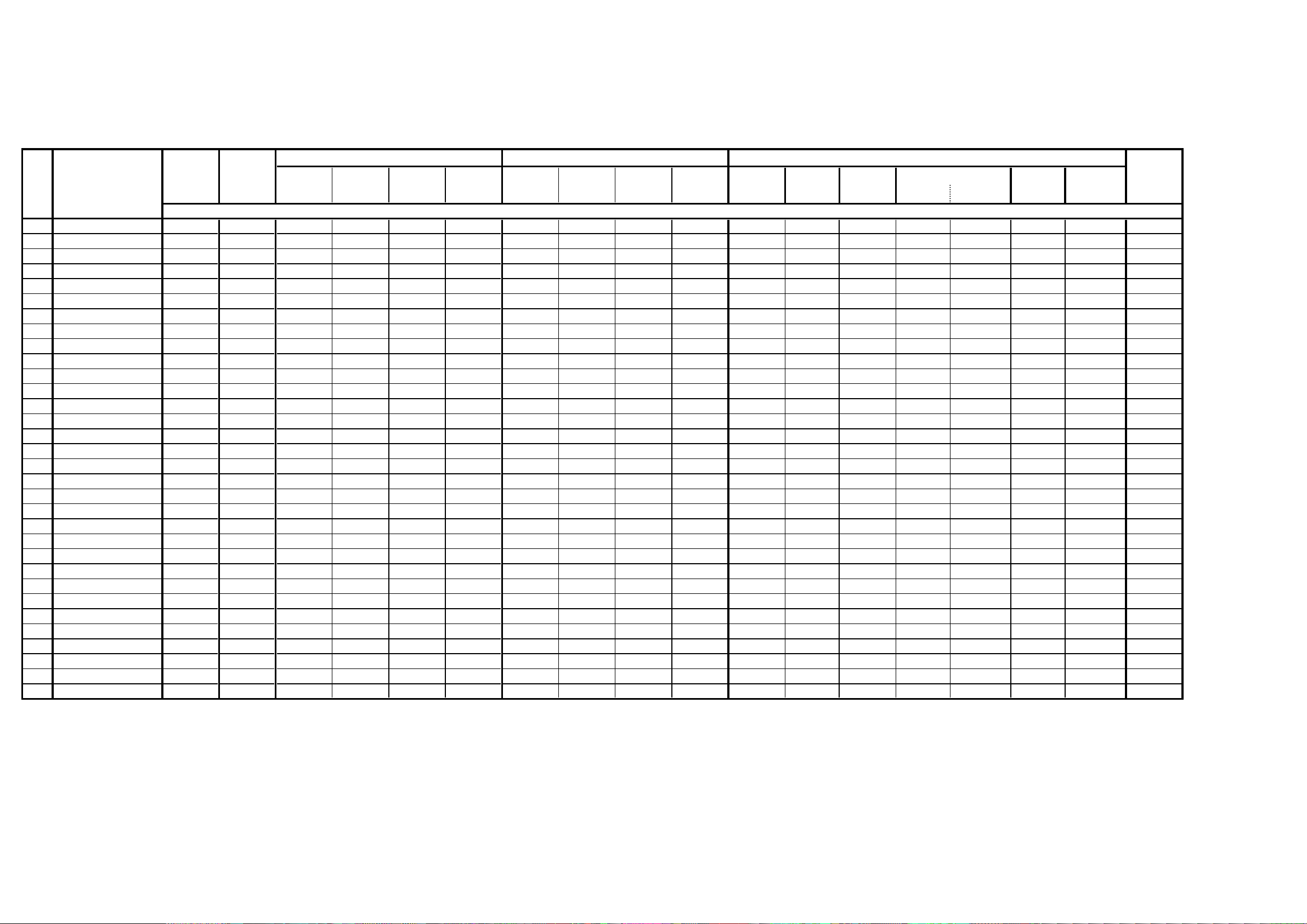
2-4: Confirmation of Fixed Value (Step No.)
Please check if the fixed values of each the adjustment items are set correctly referring below. (TV/AV/YUV/HDMI/PC/DTV)
YUV PCHD-MI
TV AV DTV
480i 480p 720p 1080i 480i 480p 720p 1080i 60*480 800*600 1024*768 1280*768 1280*720 848*480 1360*768
NO. FUNCTION
1 H POSI OSD 180 180 180 180 180 180 180 180 180 180 180 180 180 180 180 180 180 180
2 V POSI OSD 80 80 80 80 80 80 80 80 80 80 80 80 80 80 80 80 80 133
3 R DRIVE (N) 133 133 133 133 133 133 133 133 133 133 120 120 120 120 120 120 120 133
4 R CUT OFF (N) 129 129 129 129 129 129 129 129 129 129 ... ... ... ... ... ... ... 129
5 G DRIVE (N) 128 128 128 128 128 128 128 128 128 128 122 122 122 122 122 122 122 128
6 G CUT OFF (N) 128 128 128 128 128 128 128 128 128 128 ... ... ... ... ... ... ... 128
7 B DRIVE (N) 116 116 116 116 116 116 116 116 116 116 128 128 128 128 128 128 128 116
8 B CUT OFF (N) 135 135 135 135 135 135 135 135 135 135 ... ... ... ... ... ... ... 135
9 R DRIVE (C) 123 123 123 123 123 123 123 123 123 123 ... ... ... ... ... ... ... 123
10 R CUT OFF (C) 130 130 130 130 130 130 130 130 130 130 ... ... ... ... ... ... ... 130
11 G DRIVE (C) 128 128 128 128 128 128 128 128 128 128 ... ... ... ... ... ... ... 128
12 G CUT OFF (C) 128 128 128 128 128 128 128 128 128 128 ... ... ... ... ... ... ... 128
13 B DRIVE (C) 124 124 124 124 124 124 124 124 124 124 ... ... ... ... ... ... ... 124
14 B CUT OFF (C) 134 134 134 134 134 134 134 134 134 134 ... ... ... ... ... ... ... 134
15 R DRIVE (W) 135 135 135 135 135 135 135 135 135 135 ... ... ... ... ... ... ... 135
16 R CUT OFF (W) 129 129 129 129 129 129 129 129 129 129 ... ... ... ... ... ... ... 129
17 G DRIVE (W) 128 128 128 128 128 128 128 128 128 128 ... ... ... ... ... ... ... 128
18 G CUT OFF (W) 128 128 128 128 128 128 128 128 128 128 ... ... ... ... ... ... ... 128
19 B DRIVE (W) 107 107 107 107 107 107 107 107 107 107 ... ... ... ... ... ... ... 107
20 B CUT OFF (W) 137 137 137 137 137 137 137 137 137 137 ... ... ... ... ... ... ... 137
22 H POSI 60Hz 282 282 282 142 312 260 278 140 268 218 47 214 158 190 189 110 365 294
24 V POSI 60Hz 24 24 24 24 24 24 24 24 24 24 22 22 22 20 20 22 20 24
28 BRIGHT CENT 107 107 107 115 115 115 95 95 95 95 50 50 50 50 50 50 50 115
29 BRIGHT MAX 185 185 185 185 185 185 185 185 185 185 100 100 100 100 100 100 100 185
30 BRIGHT MIN 60 60 60 60 60 60 60 60 60 60 30 30 30 30 30 30 30 60
31 TINT 117 121 121 126 126 126 123 123 123 123 ... ... ... ... ... ... ... 137
35 CONTRAST CENTER 128 128 128 128 128 128 128 128 128 128 130 130 130 130 130 130 130 128
36 CONTRAST MAX 145 155 162 155 155 155 130 130 130 130 150 150 150 150 150 150 150 155
37 CONTRAST MIN 70 70 70 70 70 70 70 70 70 70 90 90 90 90 90 90 90 70
38 COLOR CENT 80 88 106 56 56 56 78 78 78 78 ... ... ... ... ... ... ... 60
39 COLOR MAX 180 180 180 180 180 180 180 180 180 180 ... ... ... ... ... ... ... 180
40COLOR MIN 0000000000.....................0
Step No.
VGA SVGA XGA WVGA WXGA
WXGA
D-3 D-4
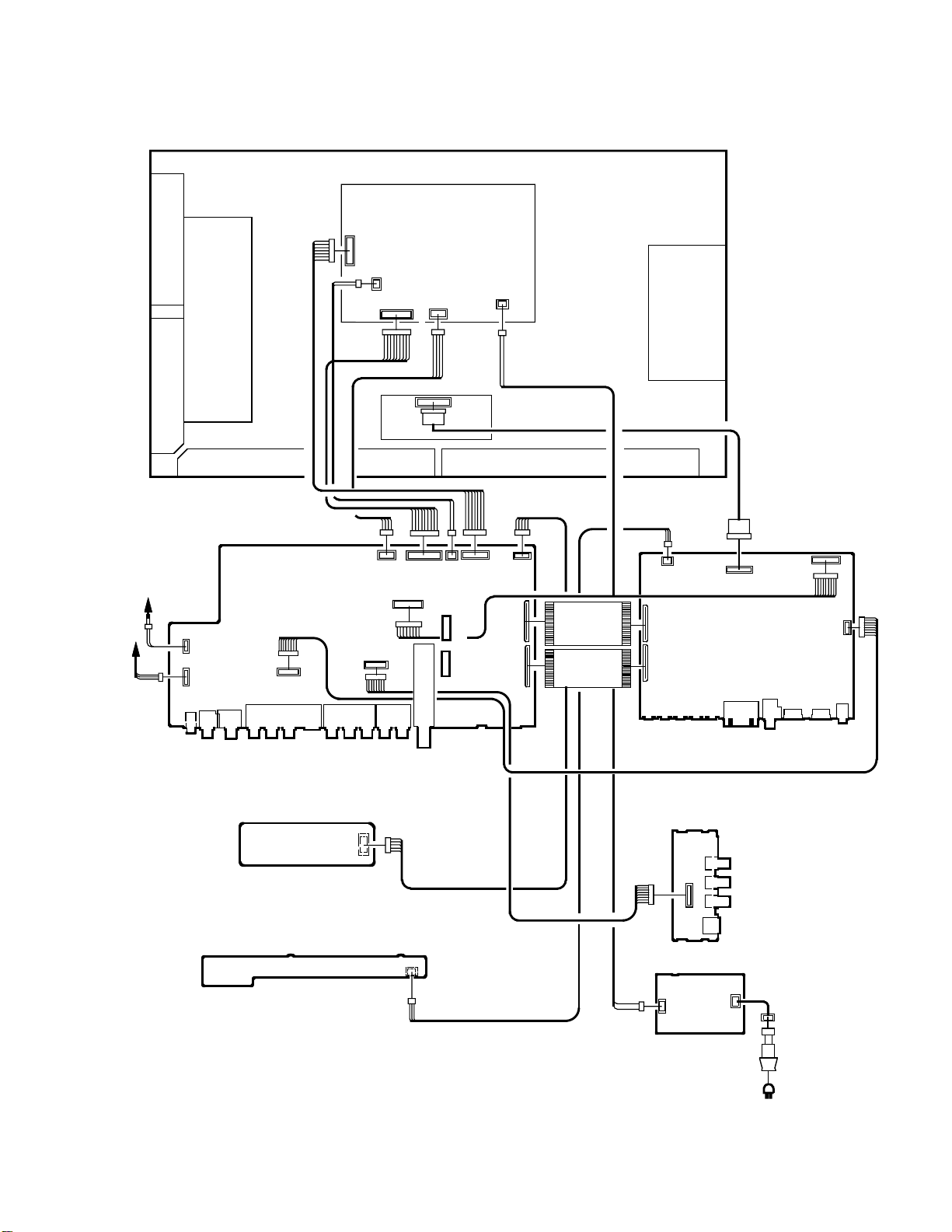
ELECTRICAL ADJUSTMENTS
3. ELECTRICAL ADJUSTMENT PARTS LOCATION GUIDE (WIRING CONNECTION)
PDP PANEL
SPEAKER
SPEAKER
J2275
CP301
CP303
J4201
CP901
J4202
J4205
REMOCON PCB
OPERATION PCB
J4211
AV PCB
CP2251
CP3801
CP4201
J4204
CP3803
CP3807
CP2203
CP3802
DIGITAL PCB
TU5801
CP3804
CP4202
CP4204
CP4203
CD4203
CD4204
CP2200
CP802
CP803
CP7202
CP4302
SCALER PCB
SIDE JACK PCB
J4209
CP4200
J4208
J4207
J4206
CP3901
CP3900
CP3201
J4301
CP3601
CP3602
CP3603
J3601
D-5
FILTER PCB
CD3810
AC IN
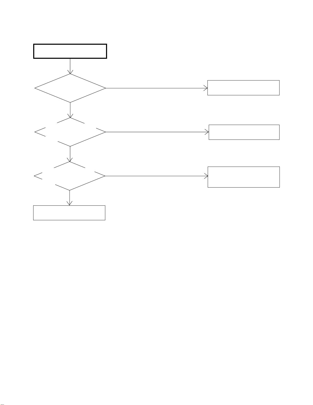
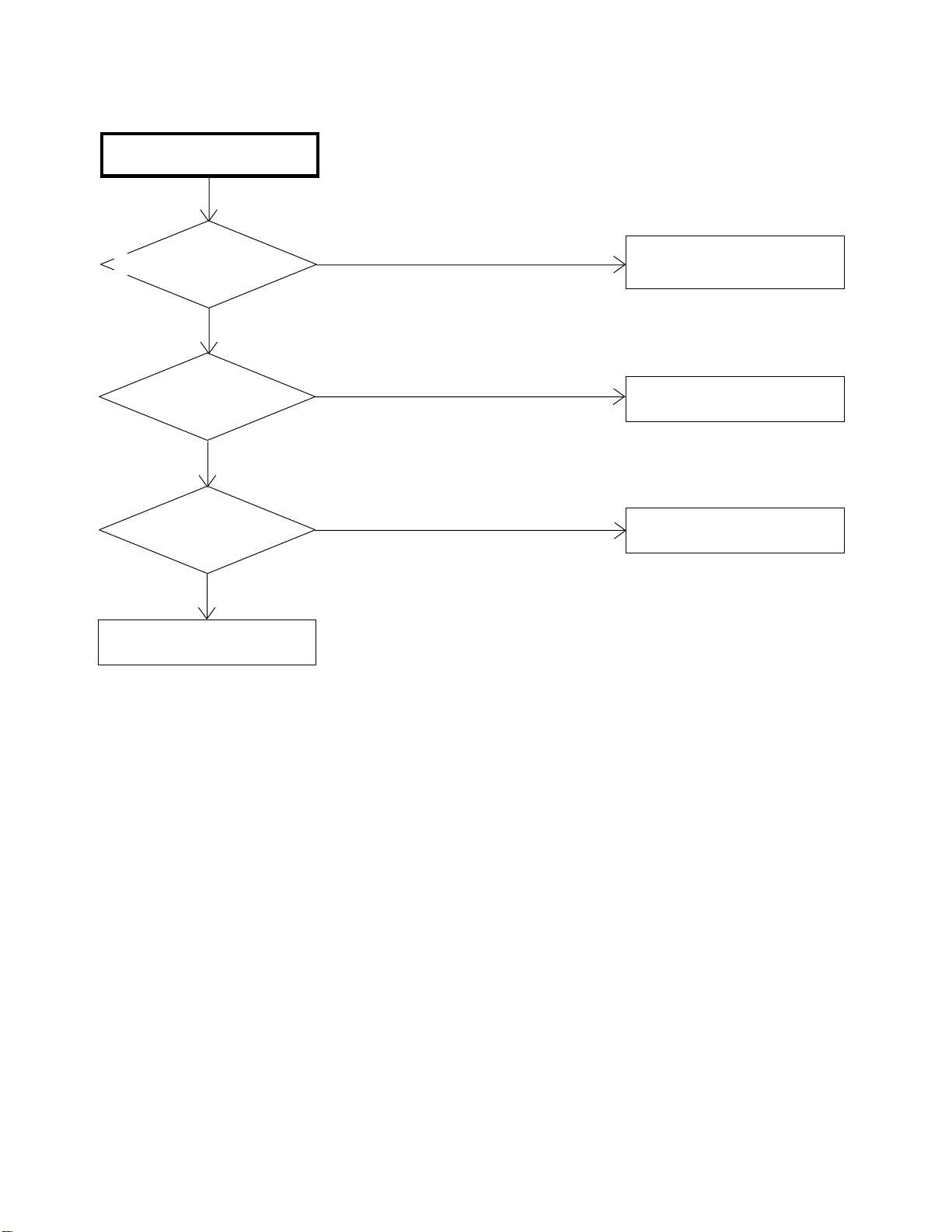
POWER DOES NOT TURN ON
TROUBLESHOOTING GUIDE
IS F3900 BROKEN ?
NO
IS THERE VOLTAGE
AT PIN 11 OF CP3201
5V ?
YES
IS THERE VOLTAGE
AT PIN 2 OF IC3804
AT3.3V ?
YES
CHANGE SCALER PCB.
YES
NO
NO
CHANGE F3900.
CHECK CP3201 AND
CP3804.
CHECK IC3804 AND
PERIPHERAL CIRCUIT.
OR CHANGE AV PCB.
E-1
THE PICTURE DOES NOT
APPEAR (1).
TROUBLESHOOTING GUIDE
IS CD3201 CONNECTED ?
YES
IS CD7204 CONNECTED ?
YES
IS THERE SIGNAL
AT IC7202 ?
YES
CHECK IC801.
OR CHANGE SCALER PCB.
NO
NO
NO
CONNECT CP3201.
CONNECT CD7202.
CHANGE IC7202.
E-2
 Loading...