

Toshiba 42DPC85 Schematic

SERVICE MANUAL
DOCUMENT CREATED IN JAPAN, Sept., 2005
Revision 1
Plasma Monitor
42DPC85
FILE NO. 020-200521
TOSHIBA CORPORATION 2005
-
1
-
Published in Japan, Sep. 2005 (YC)

TABLE OF CONTENTS
SERVICE SAFETY PRECAUTIONS .................................................................................................................................... 3
SERVICE MODE .................................................................................................................................................................. 5
LAYOUT OF MAJOR BOARDS .......................................................................................................................................... 10
MECHANICAL DISASSEMBLY .......................................................................................................................................... 11
EXPLODED VIEW .............................................................................................................................................................. 13
PACKING DISASSEMBLY ................................................................................................................................................. 15
CHASSIS AND CABINET REPLACEMENT PARTS LIST ................................................................................................. 16
PC BOARDS TOP & BOTTOM VIEW ................................................................................................................................ 19
CIRCUIT BLOCK DIAGRAM .............................................................................................................................................. 33
APPENDIX:
SCHEMATIC DIAGRAM
-
2
-
GENERAL ADJUSTMENTS
SPECIFIC INFORMATIONS
SERVICE SAFETY PRECAUTIONS
• The caution items shown here describe major safety issues and should always be observed.
• The meanings of the various indications are as follows.
WARNING
CAUTION
* Physical damage means major damage to a home, furnishings and other possessions.
Examples of marks
SHOCK HAZARD
PROHIBIT DISASSEM-
BLING
UNPULUG
Indicates a hypothetical situation in which service personnel and nearby third parties, or even
end users due to a product defect after the service operation is completed, could possibly be in
danger of injury or even death in the event of operational error.
Indicates a hypothetical situation in which service personnel and nearby third parties, or even
end users after the service operation is completed, could possibly be in danger of injury, or
where there could be physical damage in the event of operational error.
The" indicates caution (including danger and warning).
"
The actual meaning of this caution is indicated inside the
The example shown to the left indicates the danger of "electrical shock".
The
indicates a forbidden action.
The actual meaning of this caution is indicated inside the
The example shown to the left indicates that disassembly is forbidden.
The
-
indicates a forced action (an action that must be performed).
The actual meaning of this forced action is indicated by
The example shown to the left indicates that the power plug must be disconnected.
or nearby illustrations or text.
or nearby illustrations or text.
-
or nearby illustrations or text.
-
3
-
KEEP CHILDREN
AWAY
UNPULUG
SHOCK HAZARD
USE SPECIFIED
PARTS
CAUTION FOR
WIRING
CAUTION FOR
ASSEMBLING /
WIRING
WARNING
• Always advise users to keep children away.
There is danger of injury to children from tools, disassembled products, etc.
• Always disconnect the power plug before starting work whenever power is not required.
Failure to disconnect the power plug before starting work can result in electrical shock.
• Depending on the model, use an insulation transformer or wear gloves when servicing with the
power on, and disconnect the power plug to avoid electrical shock when replacing parts.
In some cases, alternating current is also impressed in the chassis, so electrical shock is possible if the chassis is contacted with the power on.
• Always use the replacement parts specified for the particular model when making repairs.
The parts used in products have the necessary safety characteristics such as inflammability,
voltage resistance, etc.; therefore, use only replacement parts that have these same characteristics.
Use only the specified parts when the
• Parts mounting and routing of the wiring should be the same as that used originally.
For safety purposes, insulating materials such as tubing or tape is sometimes used and printed
circuit boards are sometimes mounted floating.
Also make sure that wiring is routed and clamped to avoid parts that generate heat and which
use high voltage. Always follow the original scheme.
• After a repair has been completed, reassemble all disassembled parts, and route and reconnect the wiring, in accordance with the original scheme.
Do not allow internal wiring to be pinched by cabinets, panels, etc.
Any error in reassembly or wiring can result in electrical leakage, flame, etc., and may be
hazardous.
mark is included in a circuit diagram or parts list.
CHECK INSULATION
RESISTANCE
PROHIBIT
REMODELING
• After completing the work, disconnect the power plug from the outlet, remove the antenna, turn
on the power switch. Then, use a 500V insulation resistance meter to check the insulation
resistance of the antenna terminal, other metallic parts and between the prongs of the power
plug to make sure that the insulation resistance is 1M 1 or more.
The set will require inspection and repair if the insulation resistance is below this value.
• Never remodel the product in any way.
Remodeling can result in improper operation, malfunction, or electrical leakage and flame,
which may be hazardous
-
4
-
SERVICE MODE
Recall
Recall
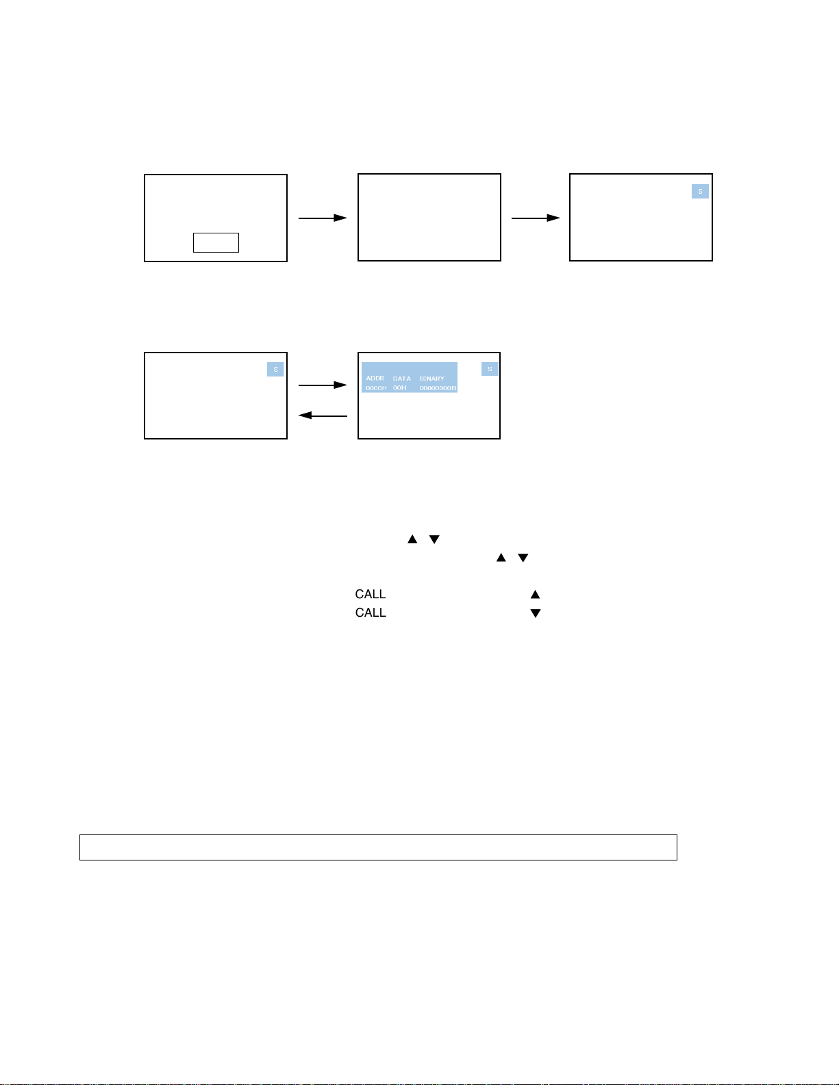
1. ENTERING SERVICE MODE
1) Press MUTE button twice on 2) Press MUTE button again and 3) While pressing the MUTE button,
Remote Control. keep pressing. press MENU button on TV set.
MUTE
2. DISPLAYING THE ADJUSTMENT MENU
1) Press MENU button on Remote Control.
Service mode Adjustment mode
Press
Press
3. KEY FUNCTION IN THE SERVICE MODE
The following key entry during display of adjustment menu provides special functions.
(Service mode display)
Test signal selection : TV/VIDEO button (on Remote)
Selection of the adjustment items : Channel
Change of the data value : Volume W / X (on TV) or
Adjustment menu mode ON/OFF : MENU button (on Remote)
Initialization of the memory : CALL + Channel button on TV ( )
Reset the count of operating protect circuit to “00” :
“RCUT” selection : 1 button
“GCUT” selection : 2 button
“BCUT” selection : 3 button
“CNTX” selection : 4 button
“COLC” selection : 5 button
“UVTT” selection : 6 button
Automatic A/D Adjustment(PC, Component) : 7 button
Self diagnostic display ON/OFF : 9 button
CAUTION : Never try to perform initialization unless you have changed the memory IC.
CALL + Channel button on TV ( )
/ (on TV or Remote)
-----
Color thickness correction
note: Displayed differently as shown below, depending
on the setting of the receiving color system.
COLP (PAL)
COLC (NTSC)
COLS (SECAM)
/ (on Remote)
-
7
-
4. SELECTING THE ADJUSTING ITEMS
Recall
1) Every pressing of CHANNEL
button for reverse order)
(
5. ADJUSTING THE DATA
1) Pressing of VOLUME W / X , / button will change the value of data in the range from 00H to FFH. The
variable range depends on the adjusting item.
6. EXIT FROM SERVICE MODE
1) Pressing POWER button to turn off the TV once.
INITIALIZATION OF MEMORY DATA
After replacing EEPROM IC, the following initialization is required.
1. Enter the service mode, then select any register item.
2. Press and hold the CALL button on the Remote, then press the CHANNEL
EEPROM IC has been completed.
3. Check the picture carefully. If necessary, adjust any adjustment item above.
Perform “Auto tune” on the owner’s manual.
CAUTION: Never attempt to initialize the data unless EEPROM IC has been replaced.
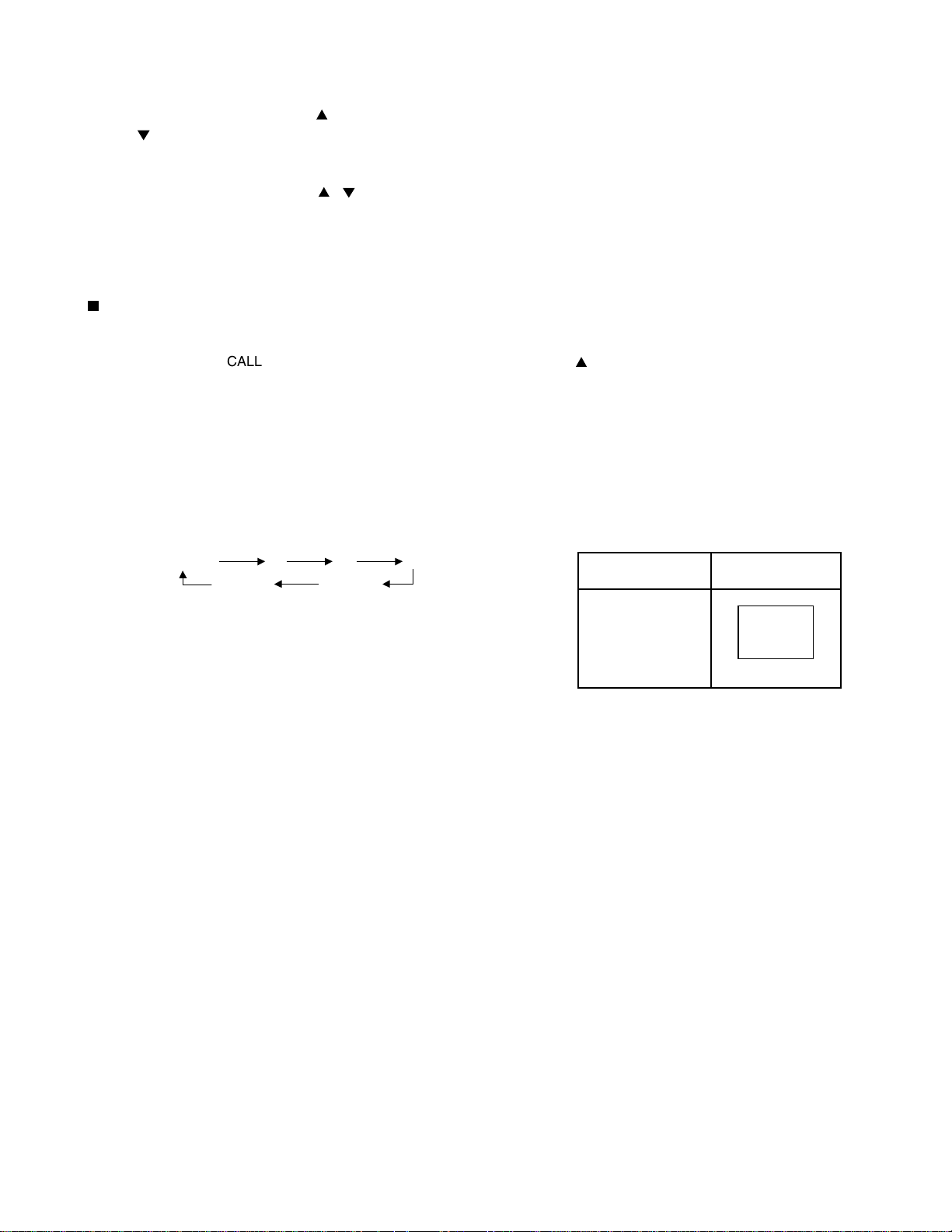
7. TEST SIGNAL SELECTION
1) Every pressing of TV/VIDEO button on the Remote Control changes the built-in test patterns on screen as described
below in SERVICE MODE.
button in the service mode changes the adjustment items in the order of table-2.
button on the TV. The initialization of
R
All BlackAll White
BSignal off G
Signals Picture
• Red raster
• Green raster
• Blue raster
• All Black
• All White
-
8
-
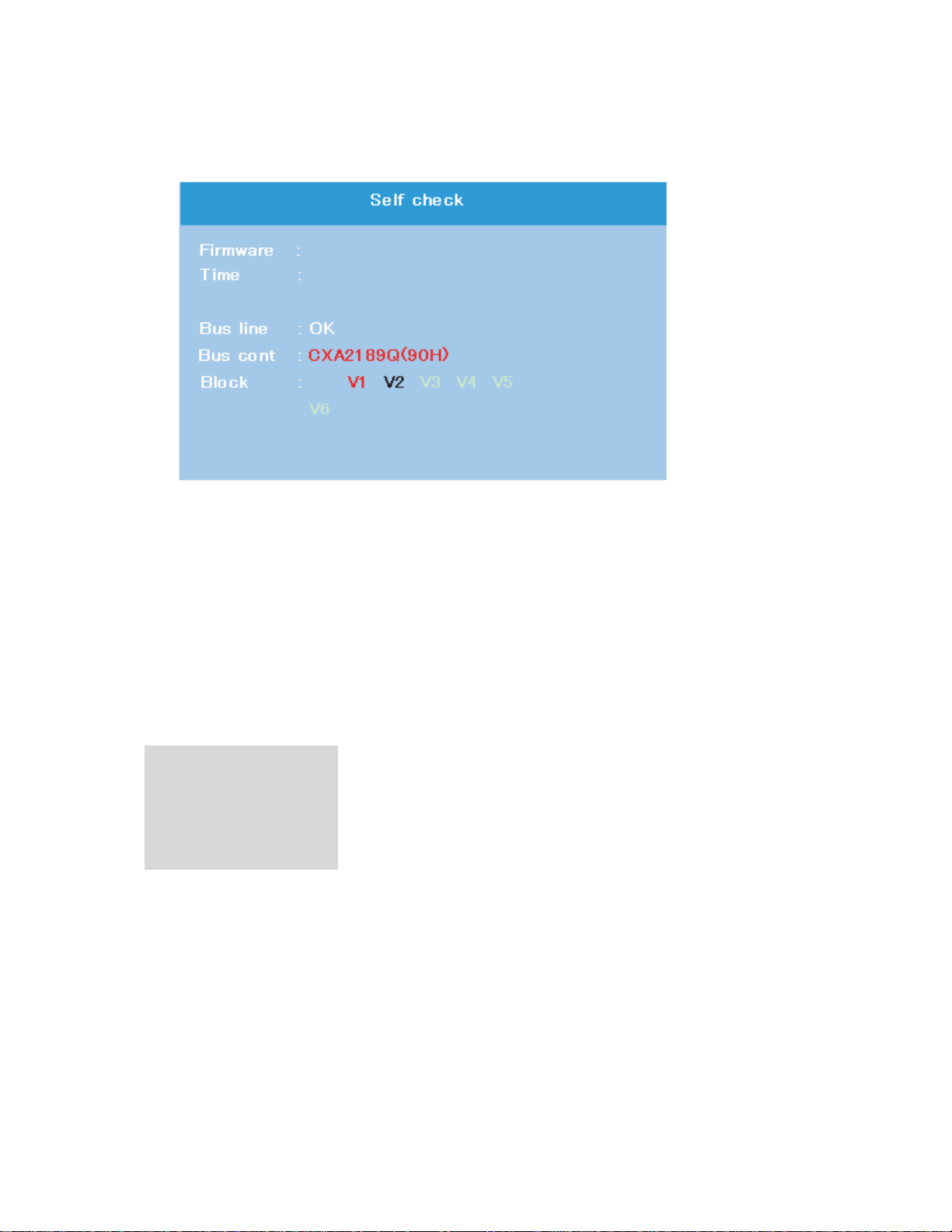
8. SELF DIAGNOSTIC FUNCTION
000000
DPC85_0100
1) Press “9” button on Remote Control during display of adjustment menu in the service mode.
The diagnosis will begin to check if interface among IC’s is executed properly.
2) During diagnosis, the following displays are shown.
M
N
O
P
Q
M Firmware :
Version information of microprocessor
In case of file name : DPC85 and Version : 0100 indicates[DPC85_0100].
N Time : Total hour of turn the TV on. (Unit : H)
O Bus line : --"OK" is normal
"SCL-GND"(Red indication) : SCL-GND short circuit
"SDA-GND"(Red indication) : SDA-GND short circuit
"SCL-SDA"(Red indication) : SCL-SDA short circuit
P Bus cont : --- "OK" is normal.
NG is abnormal(Red indication), when type name of semiconductor indicates.
Q Block
V1 : VIDEO 1 input mode
V2 : VIDEO 2 input mode
V3 : VIDEO 3 input mode
V4 : ColorStream 1 IN
V5 : ColorStream 2 IN
V6 : HDMI A/V IN
-
7
-
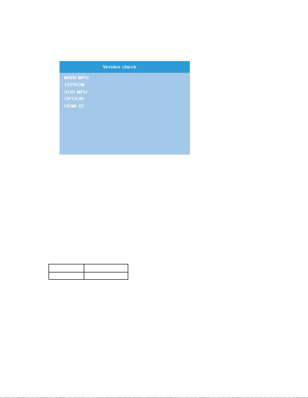
9. VERSION CHECK MODE
DPC85_0100(U15)
01
36
24 00 01 57 00 00
00000155
LG−42
1) Press “9” button twice on Remote Control during display of adjustment menu in the service mode. The version of main
MPU will begin to check.
2) During Version Check, the following displays are shown.
M
N
O
P
Q
R
M
MAIN MPU :
Version information of microprocessor
In case of file name : DPC85, Version 0100 for Code Program Version
and (U15) for OSD Version indicates [DPC85_0100(U15)]
N EEPROM :
Version information of EEPROM : Display 1 byte data.
O SUB MPU :
Version information of SUB MPU : Display 1 byte data.
P OPTION :
Option information : Display six numbers of 1 byte data.
Q HDMI ID :
HDMI ID information : Display 4 byte data.
R PDP Panel Vender information display
The following Panel Vender and screen size are displayed.
Panel Vender Screen Size(Inch)
LG -42
Example : LG-42 indicates that vender is LG and Screen Size is 42 inch.
-
8
-
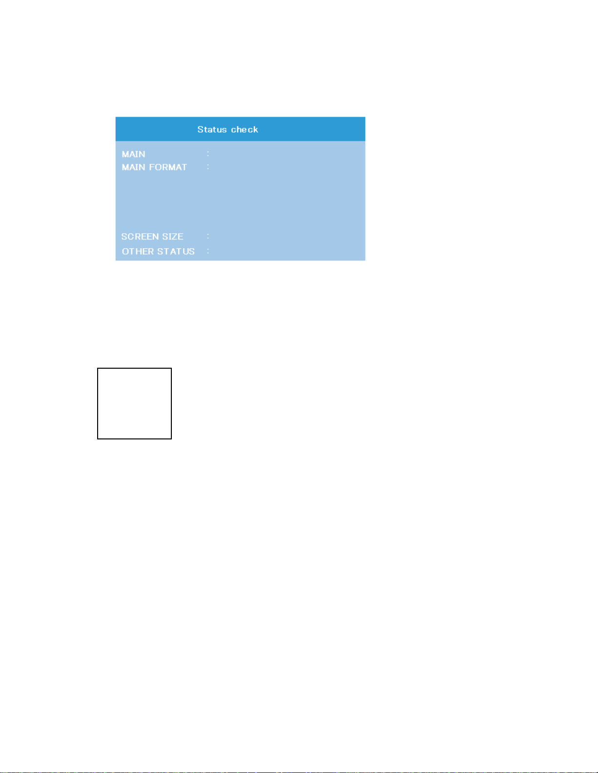
10. STATUS CHECK MODE
EXT1
480i
NATURAL
0000 0000 0000
1) Press “9” button thrice on Remote Control during display of adjustment menu in the service mode. The status of this
model will begin to check.
2) During Status Check, the following displays are shown.
M
N
O
P
M MAIN :
Main source information :
Display RF position number (0 - 99) on the main screen, or Input Source (EXT1/2/3/HDMI etc.)
N MAIN FORMAT :
Display Video and PC format information
O SCREEN SIZE :
Display the screen size as follows.
Theater Wide 1
Theater Wide 2
Theater Wide 3
FULL
NATURAL
P
OTHER STATUS :
Other status information : Display three numbers of 2 byte data.
-
9
-
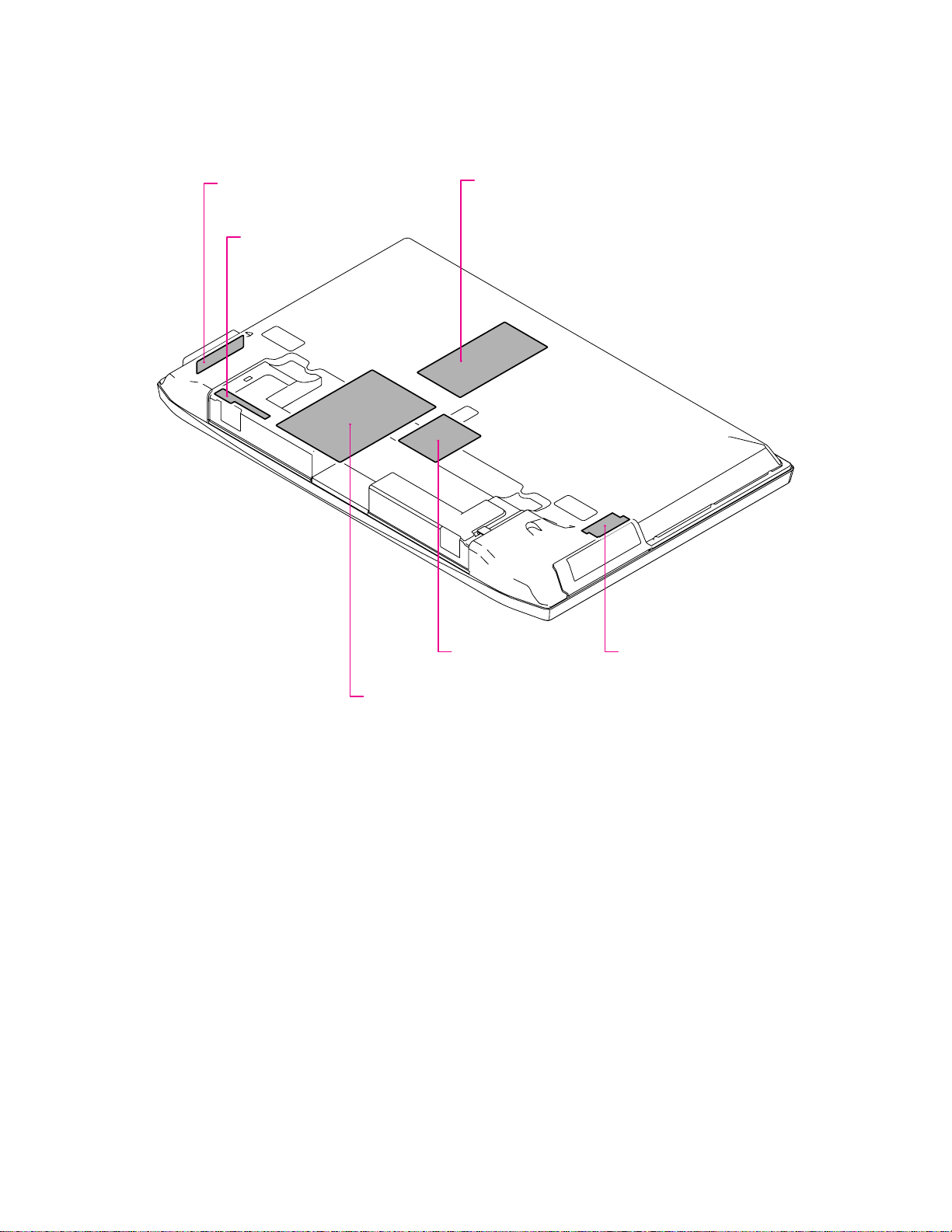
LAYOUT OF MAJOR BOARDS
U105D
KEY-SW BOARD
U105C
LED-RMT BOARD
U803
LOWB BOARD
U101
SIGNAL BOARD
U105A
AV/AOUT BOARD
U105B
FRONT AV BOARD
-
10
-
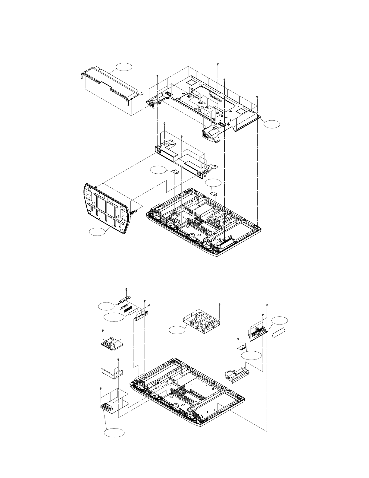
MECHANICAL DISASSEMBLY
1. Remove the stand (foot) and back cover.
A410
PP4×8 SBN ×6
PP4×8 SBN ×9
PP3×8 SBN
BITTB4×12 SBN ×14
PP6×35+SW+W
SBN×4
A403
2.
Remove the boards (AV/AOUT, FRONT AV, KEY-SW) and piece key ass'y.
PP3×8 SBN
BITTB3×8 ECO ×2
A221
U105D
BITTB3×12 SBN ×4
BITTB4×12
SBN×7
A206
PP4×8 ECO
U800
A206
PP3×8 ECO ×8
BITTB3×12
A401
PP4×12 SBN ×2
PP4×8 SBN ×2
A220
ECO×2
PP3×8 ECO
×
2
PP3×8 ECO ×6
U105A
-
11
U105B
-
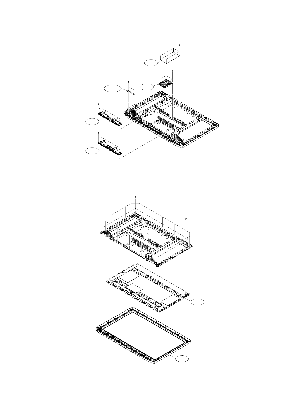
3. Remove the boards (SIGNAL, LED-RMT, LOWB) and speaker.
PP3×8 ECO ×6
U803
BITTB3×12
ECO×2
PP3×8 ECO ×4
4. Remove the display.
U105C
BITTB3×8 SBN
×
6
W662
BITTB3×8 SBN
×
6
W661
U101
BITTB4×12 ECO ×4
BITTB4×12 ECO ×19
-
12
B001
A201
-
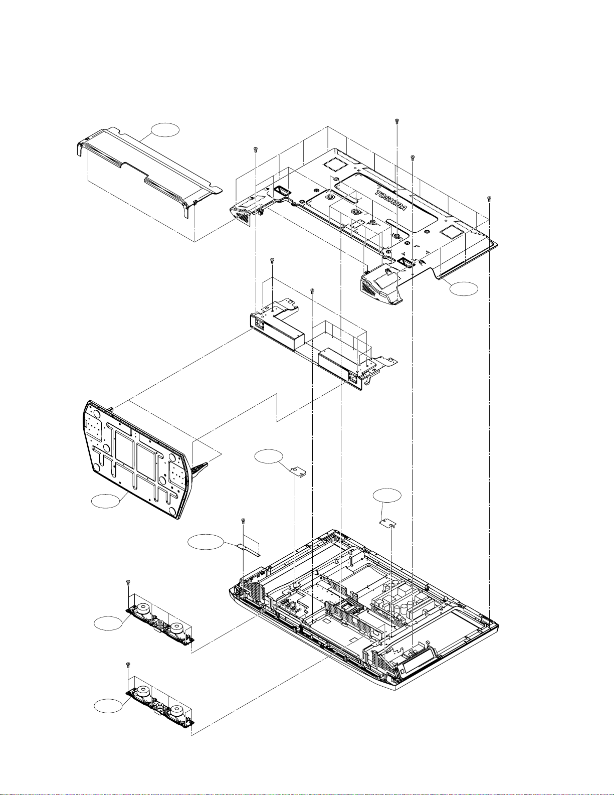
1. Chassis Block
EXPLODED VIEWS
A410
PP4×8 SBN ×6
PP6×35+SW+W
SBN×4
BITTB4×12
SBN×7
PP4×8 SBN ×9
PP3×8 SBN
BITTB4×12 SBN ×14
A401
A403
W662
W661
U105C
BITTB3×8 SBN ×6
BITTB3×8 SBN ×6
BITTB3×12
ECO×2
A206
A206
-
13
-
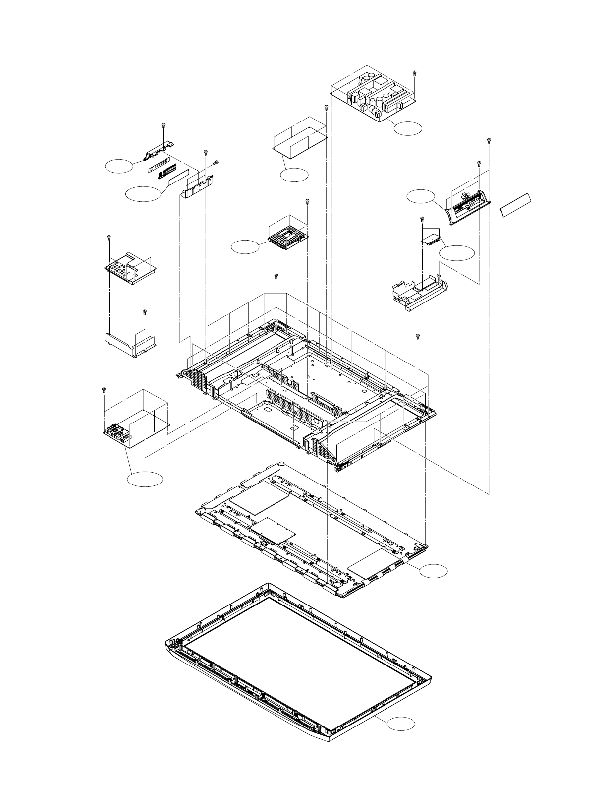
2. Main Block
PP3×8 SBN
BITTB3×8 ECO ×2
PP3×8 ECO ×8
PP3×8 ECO ×6
U800
PP4×12 SBN ×2
A221
U105D
BITTB3×12 SBN ×4
PP3×8 ECO ×2
PP3×8 ECO ×6
PP4×8 ECO
U803
PP3×8 ECO ×4
U101
BITTB4×12 ECO ×4
PP4×8 SBN ×2
A220
BITTB3×12
ECO×2
U105B
BITTB4×12 ECO ×19
U105A
-
14
B001
A201
-
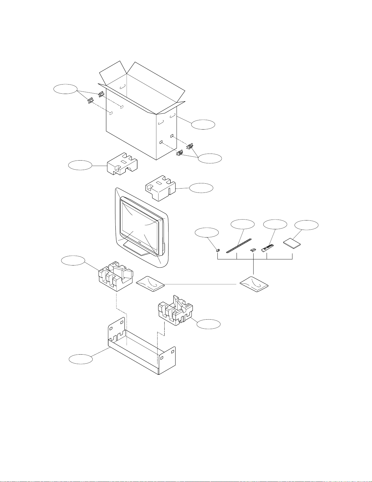
A705
PACKING DISASSEMBLY
A701A
A705
A702A
A702A
A702B
A701B
Y170
A702B
Y174
K902
Y101
-
15
-
CHASSIS AND CABINET REPLACEMENT PARTS LIST
WARNING: BEFORE SERVICING THIS CHASSIS, READ THE “SERVICE SAFETY PRECAUTIONS” ON PAGE 3 OF THIS
MANUAL.
CAUTION: The international hazard symbols " " in the schematic diagram and the parts list designate components which
have special characteristics important for safety and should be replaced only with types identical to those in the original
circuit or specified in the parts list. The mounting position of replacements is to be identical with originals. Before replacing
any of these components, read carefully the SERVICE SAFETY PRECAUTIONS. Do not degrade the safety of the receiver
through improper servicing.
NOTICE:
•
The part number must be used when ordering parts, in order to assist in processing, be sure to include the Model
number and Description.
•
The PC board assembly with ∗ mark is no longer available after the end of the production.
Model : 42DPC85
Capacitors ............. CD : Ceramic Disk PF : Plastic Film EL : Electrolytic
Resistors ............... CF : Carbon Film CC : Carbon Composition MF : Metal Film
OMF : Oxide Metal Film VR : Variable Resistor FR : Fusible Resistor
(All CD and PF capacitors are ±5%, 50V and all resistors, ±5%, 1/6W unless otherwise noted.)
Location
No.
Parts No. Description
CAPACITORS
C605 76109102 CERAMIC CHIP, 50V B 1000PF K
C606 76109102 CERAMIC CHIP, 50V B 1000PF K
C656 76797100 ELECTROLYTIC, 50V 10UF M
C660 76669479 ELECTROLYTIC, 50V 4.7UF M
C661 76669479 ELECTROLYTIC, 50V 4.7UF M
C662 76109681 CERAMIC CHIP, 50V B 680PF K
C663 76109681 CERAMIC CHIP, 50V B 680PF K
C669 76109102 CERAMIC CHIP, 50V B 1000PF K
C670 76669100 ELECTROLYTIC, 50V 10UF M
C671 76669100 ELECTROLYTIC, 50V 10UF M
C673 76619102 ELECTROLYTIC CHIP, 16V 47UF M
C674 76092731 CERAMIC CHIP, 16V B 1UF K
C677 76092731 CERAMIC CHIP, 16V B 1UF K
C678 76285104 CERAMIC CHIP, 50V B 0.1UF K
C679 76285104 CERAMIC CHIP, 50V B 0.1UF K
C680 76668102 ELECTROLYTIC, 35V 1000UF M 3A
C681 76073073 ELECTROLYTIC, 35V 2200UF M 3A
C682 76073073 ELECTROLYTIC, 35V 2200UF M 3A
C684 76109103 CERAMIC CHIP, 50V B 0.01UF K
C685 76092538 CERAMIC CHIP, 10V F 1UF Z
C690 76664102 ELECTROLYTIC, 6.3V 1000UF M 3A
C691 76092463 CERAMIC CHIP, 16V B 0.22UF K
C692 76092463 CERAMIC CHIP, 16V B 0.22UF K
C6600 76092731 CERAMIC CHIP, 16V B 1UF K
C6601 76092726 CERAMIC CHIP, 10V B 2.2UF K
C6602 76092726 CERAMIC CHIP, 10V B 2.2UF K
C6603 76092726 CERAMIC CHIP, 10V B 2.2UF K
C6604 76092726 CERAMIC CHIP, 10V B 2.2UF K
C6605 76092515 CERAMIC CHIP, 16V F 4.7UF Z
C6606 76092726 CERAMIC CHIP, 10V B 2.2UF K
C6607 76092726 CERAMIC CHIP, 10V B 2.2UF K
C6615 76092726 CERAMIC CHIP, 10V B 2.2UF K
C6616 76092726 CERAMIC CHIP, 10V B 2.2UF K
CB01 76202221 ELECTROLYTIC, 10V 220UF M 7L 3A
CB02 76202221 ELECTROLYTIC, 10V 220UF M 7L 3A
CB03 76100104 CERAMIC CHIP, 25V F 0.1UF Z
CB04 76100104 CERAMIC CHIP, 25V F 0.1UF Z
CB05 76202221 ELECTROLYTIC, 10V 220UF M 7L 3A
CB38 76100104 CERAMIC CHIP, 25V F 0.1UF Z
CC01 76109102 CERAMIC CHIP, 50V B 1000PF K
Location
No.
CC02 76109102 CERAMIC CHIP, 50V B 1000PF K
CC03 76109102 CERAMIC CHIP, 50V B 1000PF K
CC04 76109102 CERAMIC CHIP, 50V B 1000PF K
CC05 76109102 CERAMIC CHIP, 50V B 1000PF K
CC06 76109102 CERAMIC CHIP, 50V B 1000PF K
CC07 76109102 CERAMIC CHIP, 50V B 1000PF K
CC08 76109102 CERAMIC CHIP, 50V B 1000PF K
CC10 76109102 CERAMIC CHIP, 50V B 1000PF K
CC11 76109102 CERAMIC CHIP, 50V B 1000PF K
CC12 76109102 CERAMIC CHIP, 50V B 1000PF K
CC13 76109102 CERAMIC CHIP, 50V B 1000PF K
CC14 76109102 CERAMIC CHIP, 50V B 1000PF K
CC15 76109102 CERAMIC CHIP, 50V B 1000PF K
CE03 76539104 PLASTIC FILM, 50V 0.1UF J
CE05 76073090 ELECTROLYTIC, 50V 100UF M 3A
CE10 76666470 ELECTORLYTIC, 16V 47UF M 3A
CE11 76539474 PLASTIC FILM, 50V 0.47UF J
CE12 76666470 ELECTORLYTIC, 16V 47UF M 3A
CE60 76073186 ELECTROLYTIC, 35V 470UF M
CE61 76617028 ELECTROLYTIC, 16V 1200UF M
CE62 76073020 ELECTROLYTIC, 10V 1000UF M 3A
CE63 76539104 PLASTIC FILM, 50V 0.1UF J
CE64 76539104 PLASTIC FILM, 50V 0.1UF J
CE65 76666470 ELECTORLYTIC, 16V 47UF M 3A
CE66 76539474 PLASTIC FILM, 50V 0.47UF J
CE67 76666470 ELECTORLYTIC, 16V 47UF M 3A
CE85 76666470 ELECTORLYTIC, 16V 47UF M 3A
CV38 76109102 CERAMIC CHIP, 50V B 1000PF K
CV68 76797010 ELECTROLYTIC, 50V 1UF M
CV72 76794471 ELECTROLYTIC, 16V 470UF M
CV74 76794101 ELECTROLYTIC, 16V 100UF M
CV76 76100104 CERAMIC CHIP, 25V F 0.1UF Z
CV122 76105101 CERAMIC CHIP, 50V CH 100PF J
CY650 76109103 CERAMIC CHIP, 50V B 0.01UF K
Parts No. Description
RESISTORS
R264 76871750 CHIP, 1/8W 75 OHM J
R265 76871750 CHIP, 1/8W 75 OHM J
R266 76871750 CHIP, 1/8W 75 OHM J
R286 76871750 CHIP, 1/8W 75 OHM J
R287 76871750 CHIP, 1/8W 75 OHM J
-
16
-

Location
No.
R288 76871750 CHIP, 1/8W 75 OHM J
R657 76011473 CHIP, 1/20W 47K OHM J
R658 76011473 CHIP, 1/20W 47K OHM J
R659 76011103 CHIP, 1/20W 10K OHM J
R664 76011104 CHIP, 1/20W 100K OHM J
R670 76011472 CHIP, 1/20W 4.7K OHM J
R671 76011472 CHIP, 1/20W 4.7K OHM J
R672 76011182 CHIP, 1/20W 1.8K OHM J
R673 76011182 CHIP, 1/20W 1.8K OHM J
R678 76871229 CHIP, 1/8W 2.2 OHM J
R679 76871229 CHIP, 1/8W 2.2 OHM J
R680 76011473 CHIP, 1/20W 47K OHM J
R681 76011473 CHIP, 1/20W 47K OHM J
R683 76011103 CHIP, 1/20W 10K OHM J
R684 76011104 CHIP, 1/20W 100K OHM J
R685 76011222 CHIP, 1/20W 2.2K OHM J
R686 76011102 CHIP, 1/20W 1K OHM J
R687 76871102 CHIP, 1/8W 1K OHM J
R688 76871102 CHIP, 1/8W 1K OHM J
R689 76871102 CHIP, 1/8W 1K OHM J
R690 76011473 CHIP, 1/20W 47K OHM J
R691 76011103 CHIP, 1/20W 10K OHM J
R692 76011223 CHIP, 1/20W 22K OHM J
R693 76871102 CHIP, 1/8W 1K OHM J
R694 76871102 CHIP, 1/8W 1K OHM J
R695 76871102 CHIP, 1/8W 1K OHM J
R6603 76011223 CHIP, 1/20W 22K OHM J
R6604 76011102 CHIP, 1/20W 1K OHM J
R6605 76011103 CHIP, 1/20W 10K OHM J
R6606 76011104 CHIP, 1/20W 100K OHM J
R6614 76011102 CHIP, 1/20W 1K OHM J
R6615 76011102 CHIP, 1/20W 1K OHM J
R6616 76011104 CHIP, 1/20W 100K OHM J
R6617 76011104
R6620 76011101 CHIP, 1/20W 100 OHM J
R6622 76011100 CHIP, 1/20W 10 OHM J
R6623 76011100 CHIP, 1/20W 10 OHM J
R6624 76011100 CHIP, 1/20W 10 OHM J
R6625 76011104 CHIP, 1/20W 100K OHM J
R6626 76011104 CHIP, 1/20W 100K OHM J
R6627 76011104 CHIP, 1/20W 100K OHM J
R6628 76011104 CHIP, 1/20W 100K OHM J
R6629 76011222 CHIP, 1/20W 2.2K OHM J
R6633 76011101 CHIP, 1/20W 100 OHM J
R6634 76011100 CHIP, 1/20W 10 OHM J
R6635 76011104 CHIP, 1/20W 100K OHM J
R6636 76011104 CHIP, 1/20W 100K OHM J
R6638 76011473 CHIP, 1/20W 47K OHM J
R6639 76011473 CHIP, 1/20W 47K OHM J
R6657 76011100 CHIP, 1/20W 10 OHM J
R6658 76011104 CHIP, 1/20W 100K OHM J
R6659 76011101 CHIP, 1/20W 100 OHM J
R6660 76011104 CHIP, 1/20W 100K OHM J
RA71 76011683 CHIP, 1/20W 68K OHM J
RA72 76011223 CHIP, 1/20W 22K OHM J
RA73 76011103 CHIP, 1/20W 10K OHM J
RA74 76000445 CHIP JUMPER, 1608TYPE
RA77 76011103 CHIP, 1/20W 10K OHM J
RA78 76000445 CHIP JUMPER, 1608TYPE
RA79 76000445 CHIP JUMPER, 1608TYPE
RB08 76011470 CHIP, 1/20W 47 OHM J
RB09 76011470 CHIP, 1/20W 47 OHM J
RB15 76011471 CHIP, 1/20W 470 OHM J
RB24 76000445 CHIP JUMPER, 1608TYPE
RC01 76011101 CHIP, 1/20W 100 OHM J
RC02 76011101 CHIP, 1/20W 100 OHM J
Parts No. Description
CHIP, 1/20W 100K OHM J
Location
No.
RC03 76011101 CHIP, 1/20W 100 OHM J
RC04
RC05 76011101 CHIP, 1/20W 100 OHM J
RC06 76011101 CHIP, 1/20W 100 OHM J
RC07 76011101 CHIP, 1/20W 100 OHM J
RC08 76011101 CHIP, 1/20W 100 OHM J
RC09 76011101 CHIP, 1/20W 100 OHM J
RC10 76011101 CHIP, 1/20W 100 OHM J
RC11 76011101 CHIP, 1/20W 100 OHM J
RC12 76011101 CHIP, 1/20W 100 OHM J
RE04 76366222 CARBON FILM, 1/6W 2.2K OHM J
RE06 76366473 CARBON FILM, 1/6W 47K OHM J
RE10 76367180 CARBON FILM, 1/6W 18 OHM G
RE11 76367222 CARBON FILM, 1/6W 2.2K OHM G
RE12 76366472 CARBON FILM, 1/6W 4.7K OHM J
RE13 76366102 CARBON FILM, 1/6W 1K OHM J
RE15 76366182 CARBON FILM, 1/6W 1.8K OHM J
RE16 76366473 CARBON FILM, 1/6W 47K OHM J
RE17 76366103 CARBON FILM, 1/6W 10K OHM J
RE18 76366153 CARBON FILM, 1/6W 15K OHM J
RE19 76366473 CARBON FILM, 1/6W 47K OHM J
RE60 76000142 METAL FILM, 1/4W 240 OHM F
RE61 76000360 METAL FILM, 1/4W 1.2K OHM F
RE63 76366102 CARBON FILM, 1/6W 1K OHM J
RE65 76367620 CARBON FILM 1/6W 62 G
RE66 76367222 CARBON FILM, 1/6W 2.2K OHM G
RE85 76552222 OXIDE METAL FILM, 1/2W 2.2K OHM J
RE86 76366103 CARBON FILM, 1/6W 10K OHM J
RV40 76871750 CHIP, 1/8W 75 OHM J
RV41 76000445 CHIP JUMPER, 1608TYPE
RV42 76000445 CHIP JUMPER, 1608TYPE
RV43 76000445 CHIP JUMPER, 1608TYPE
RV44 76000445 CHIP JUMPER, 1608TYPE
RV76 76011750 CHIP, 1/20W 75 OHM J
RV123 76872750 CHIP, 1/16W 75 OHM J
RV330 76871750 CHIP, 1/8W 75 OHM J
RV331 76011101 CHIP, 1/20W 100 OHM J
RV340 76871750 CHIP, 1/8W 75 OHM J
RV370 76871750 CHIP, 1/8W 75 OHM J
RV376 76000445 CHIP JUMPER, 1608TYPE
RV377 76000445 CHIP JUMPER, 1608TYPE
Parts No. Description
76011101 CHIP, 1/20W 100 OHM J
COIL & TRANSFORMERS
LC01 23103828 INDUCTOR, BEAD, TEM2121M
LC02 23103828 INDUCTOR, BEAD, TEM2121M
LE10 23289980 COIL, PEAKING, TRF4220AZ
LE60 23248456 COIL, CHOKE, TLN3540AH
LE61 23289980 COIL, PEAKING, TRF4220AZ
LE62 23248387 COIL, CHOKE 9X11H 22MMHK 2.5A TLN3499AA
LV121 23277002 FERRITE CORE, ACM3225-102-2PT100
LV200 23103272 FILTER, EMI 2012 361OHM 0.22A TEM2034AD
LV201 23103272 FILTER, EMI 2012 361OHM 0.22A TEM2034AD
LV202 23103272 FILTER, EMI 2012 361OHM 0.22A TEM2034AD
LV203 23103272 FILTER, EMI 2012 361OHM 0.22A TEM2034AD
LV204 23103272 FILTER, EMI 2012 361OHM 0.22A TEM2034AD
LV205 23103272 FILTER, EMI 2012 361OHM 0.22A TEM2034AD
LV206 23103272 FILTER, EMI 2012 361OHM 0.22A TEM2034AD
LV207 23103272 FILTER, EMI 2012 361OHM 0.22A TEM2034AD
LV208 23103272 FILTER, EMI 2012 361OHM 0.22A TEM2034AD
LV209 23103272 FILTER, EMI 2012 361OHM 0.22A TEM2034AD
LV284 23277002 FERRITE CORE, ACM3225-102-2PT100
SEMICONDUCTORS
Q651 23205325 TRANSISTOR, RN2404(F)
Q652 23205302 TRANSISTOR, 2SC3326-B(F)
Q653 23205302 TRANSISTOR, 2SC3326-B(F)
-
17
-
Location
No.
Q660 23205506 TRANSISTOR, 2SC4081 Q
Q661 23205506 TRANSISTOR, 2SC4081 Q
Q664 23205506 TRANSISTOR, 2SC4081 Q
Q665 23205325 TRANSISTOR, RN2404(F)
Q670 23085039 IC, TA8246AHQ
Q671 23205302 TRANSISTOR, 2SC3326-B(F)
Q672 23205302 TRANSISTOR, 2SC3326-B(F)
Q673 23205443 TRANSISTOR, 2SA1162-Y(F)
Q6600 23009613 IC, CD4052BNSR
Q6603 23205329 TRANSISTOR, RN1404(F)
Q6604 23205329 TRANSISTOR, RN1404(F)
QB07 23205463 TRANSISTOR, 2SC2712-Y(TE85L,F)
QE02 23205313 TRANSISTOR, 2SC1815-Y(F)
QE03 23205315 TRANSISTOR, RN1206(F)
QE04 23205313 TRANSISTOR, 2SC1815-Y(F)
QE10 23135077 IC, SI-3090CA
QE11 23205315 TRANSISTOR, RN1206(F)
QE60 23085381 IC, SI-8050SS
QE65 23135076 IC, SI-3050C
QE85 23205339 TRANSISTOR, 2SC2655-Y(F)
QV16 23085823
D607 23357802 DIODE, ZENER, MA8330-M
D670 23362140 DIODE, KDS160-RTK
D671 23362140 DIODE, KDS160-RTK
D672 23357744 DIODE, ZENER, MA8056-L
D674 23362140 DIODE, KDS160-RTK
D675 23362140 DIODE, KDS160-RTK
D676 23362140 DIODE, KDS160-RTK
D678 23362140 DIODE, KDS160-RTK
DB01 23358606 DIODE, LED RED, SLR-56VC3FPQ
DB20 23357406 DIODE, ZENER, UDZS5.6B
DB22 23357703 DIODE, 1SS355
DB23 23357703 DIODE, 1SS355
DE01 23357706 DIODE, AK04
DE02 23357706 DIODE, AK04
DE03 23357823 DIODE, ZENER, MTZJ3.6A
DE05 23357499 DIODE, ERB12-01
DE07 23357821 DIODE, ZENER, MTZJ3.3A
DE60 23357810 DIODE, FMB-G14L
DE61 23357697 DIODE, 1SS133
DE62 23357845 DIODE, ZENER, MTZJ7.5B
DE85 23357861 DIODE, ZENER, MTZJ11A
DE86 23357697 DIODE, 1SS133
DE99 23357840 DIODE, ZENER, MTZJ6.2B
Parts No. Description
IC, 2IN-1OUTSW 6DBAMP CLP(PB F MM1508XNRE
MISCELLANEOUS
B001 23301670 DISPLAY, PDP42V70440
B001A 23405525 OPTICAL FILTER, PDP42V T40 SSC PM00TZ001
B205 23940542 PIECE, AV COVER ASSEMBLY 42DPC85
B213 23717219 SCREW, PP3X8+SW+W SBN
B214 23717214 SCREW, BITTB3X12SBN
FE20 23144373
GR605 76000445 CHIP JUMPER, 1608TYPE
KB01 23009710 REMOCON RECEIVER, GP1UE281RK
MJ22 23389359 CABLE, FFC 0.5 50P L70 GOLD
MJ60 23389359 CABLE, FFC 0.5 50P L70 GOLD
MZ01 23368939 CABLE, LVDS 600MM PDP1
N110 23969797 TAPE
P601 23713755 PLUG, 4P 2.5MM G, B4B-EH-F1-TV4
P602A 23713938 CONNECTOR, CONNECT B5B-PH-K-S(LF)
P602B 23713938 CONNECTOR, CONNECT B5B-PH-K-S(LF)
P661 23023302 EARPHONE JACK
P801 23372249 POWER CORD, LU/CSA 2M
P803A 23713763 PLUG, NP 2.5MM G, B12B-EH-F1A
P803B 23713763 PLUG, NP 2.5MM G, B12B-EH-F1A
P804A 23713757 PLUG, 6P 2.5MM G, B6B-EH-F1-TV4
FUSE, RADIAL LEAD SUB-MINIATUR 250V 630MA
Location
No.
P804B 23713757 PLUG, 6P 2.5MM G, B6B-EH-F1-TV4
P807A 23367072 PLUG, NP 2.5MM G JST-EH, B12B-EH-F1A
P809A 23367071 PLUG, NP 2.5MM G JST-EH, B11B-EH-F1A
P881 23023131 INLET, NOISE FILTER, GL-2080FVP-L
PJ21A 23713934 CONNECTOR, 2MM 3P S WHT B3B-PH-K-S(LF)
PJ22A 23757176 CONNECTOR, IRS 9637S-50Y902 GLD
PJ41C 23713943 CONNECTOR, CONNECT B11B-PH-K-S(LF)
PJ60A 23757176 CONNECTOR, IRS 9637S-50Y902 GLD
PP01 23974994 BAND, KESSOKU
PP03 23845859 HOLDER, WIRE, PVC-C0AT, L=70MM
PP05 23974994 BAND, KESSOKU
PV01 23023473 JACK, PIN 1S6P SMK LAP5030-0113F
PV02 23023315 JACK, PIN 7P SMK LAP5030-0203F
PV03 23023313 JACK, PIN 5P, LAP5030-0201G
PV05 23023474 JACK, PIN 3P SMK LAP5030-0216F
PV60 23365275 JACK, PHONO 3P V-L-R YKC21
Q670B 23717240 SCREW
QE10B 23717240 SCREW
SA01 23344507 SWITCH, PUSH, SKHHLMA010
SA02 23344507 SWITCH, PUSH, SKHHLMA010
SA03 23344507 SWITCH, PUSH, SKHHLMA010
SA04 23344507 SWITCH, PUSH, SKHHLMA010
SA05 23344507 SWITCH, PUSH, SKHHLMA010
SA06 23344507 SWITCH, PUSH, SKHHLMA010
SA07 23344507 SWITCH, PUSH, SKHHLMA010
U800 23122502
W661 23351320
W662 23351320
ZA01 23103778 FERRITE CORE, TFE1008
ZA02 23103839 FERRITE CORE, TFE1012
ZA03 23103840 FERRITE CORE, TFE1013
ZA04 23103914 FERRITE CORE, TFE1015AD
Parts No. Description
POWER UNIT, POWER BLOCK MODULE 1H276W
SPEAKER, ASSY, 6X12 8-OHM 10W SPK-1468AO
SPEAKER, ASSY, 6X12 8-OHM 10W SPK-1468AO
PC BOARD ASSEMBLIES
U101 75001688 PC BOARD ASSY, PD2222D1 SIGNAL
*
U105A 75001689 PC BOARD ASSY, PD2239A1 AV/AOUT
*
U105B 75001690 PC BOARD ASSY, PD2239A2 FRONT AV
*
U105C 75001691 PC BOARD ASSY, PD2239A3 LED-RMT
*
U105D 75001692 PC BOARD ASSY, PD2239A4 KEY-SW
*
U803 75001687 PC BOARD ASSY, PD2202F1 LOWB
*
ACCESSORIES
A701A 23015211 CARTON, TOP CASE 42DPC85
A701B 23015181 CARTON, BOTTOM CASE
A702A 23580047 PACKING, TOP PACKING
A702B 23580048 PACKING, BOTTOM PACKING
A705 23518043 PACKING, JOINT
K902 23306626 REMOCON HAND UNIT IR, MTVUSA CT-90232
Y101 23566768 OWNERS MANUAL, ENGLISH/FRENCH 42DPC85
Y170 23845800 HOLDER, WIRE, NYLON66 D6.8
Y174 23845510 BAND
CABINET PARTS
A201 23533667 COVER, FRONT BEZEL ASSY 42DPC85
A206 23469406 INSULATOR, INSULATOR
A220 23940543 PIECE, PIECE FRONT AV ASSY 42DPC85
A221 23940544 PIECE, PIECE CONTROL ASSY 42DPC85
A231 23717214 SCREW, BITTB3X12SBN
A235 23717177 SCREW, PP5X12+SW+W SBN
A237 23717250 SCREW, PP4X12+SW+W SBN
A401 23533556 COVER, BACK COVER ASSY
A403 23436887 FOOT, STAND ASSY
A410 23533616 COVER, CABLE COVER PROPER
A423 23717217 SCREW, PP6X35+SW+W SBN
-
18
-
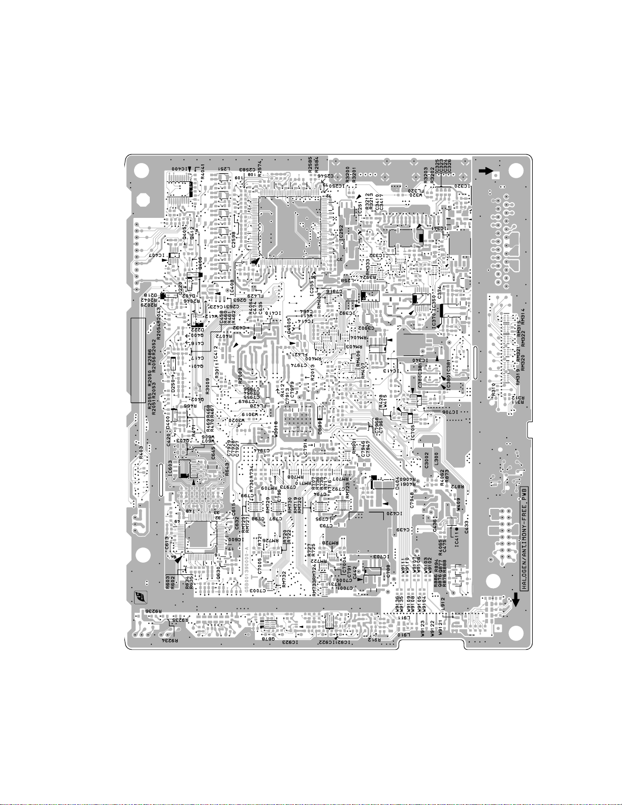
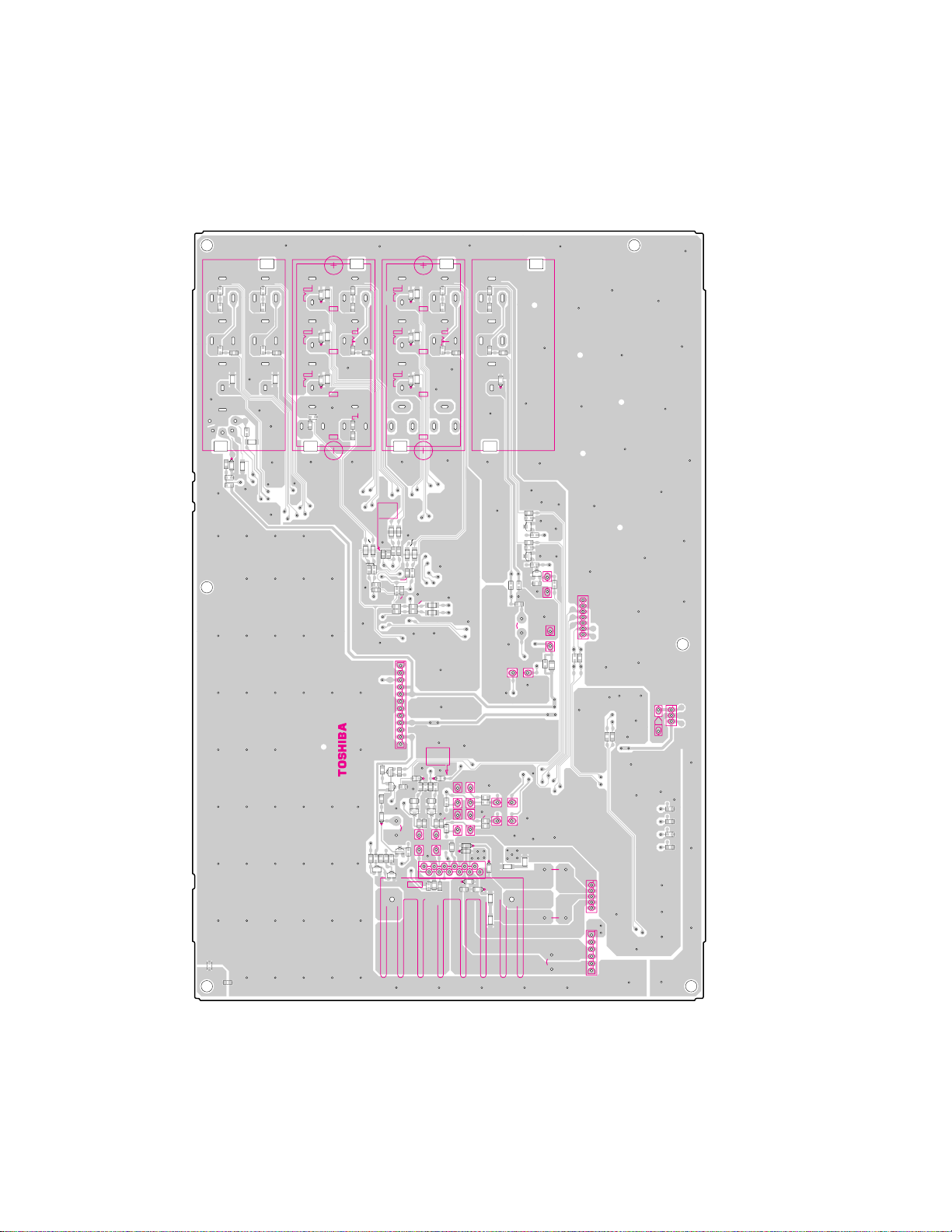
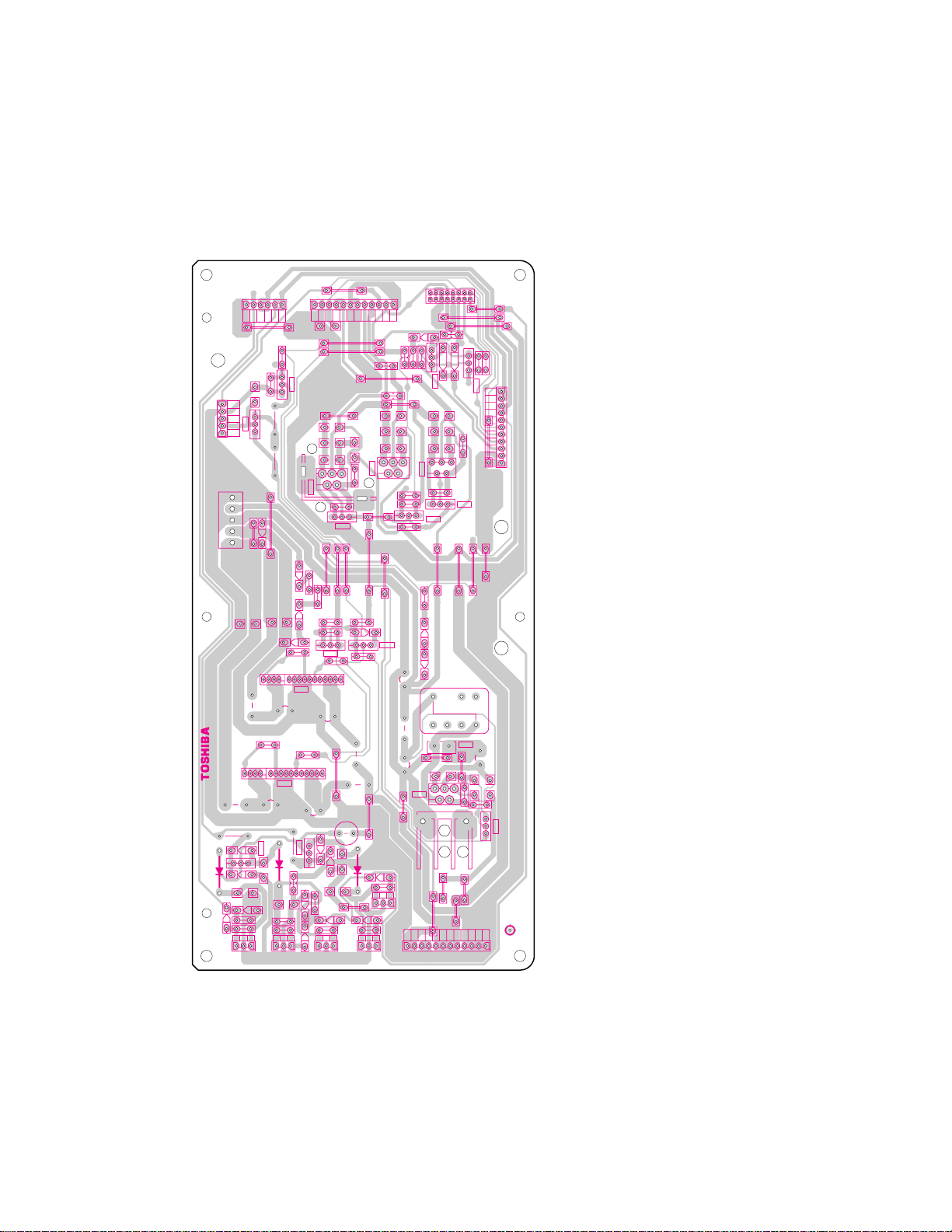
BOTTOM (FOIL) SIDE
SIGNAL BOARD PD2222D1 (U101)
-
20
- -
19
-
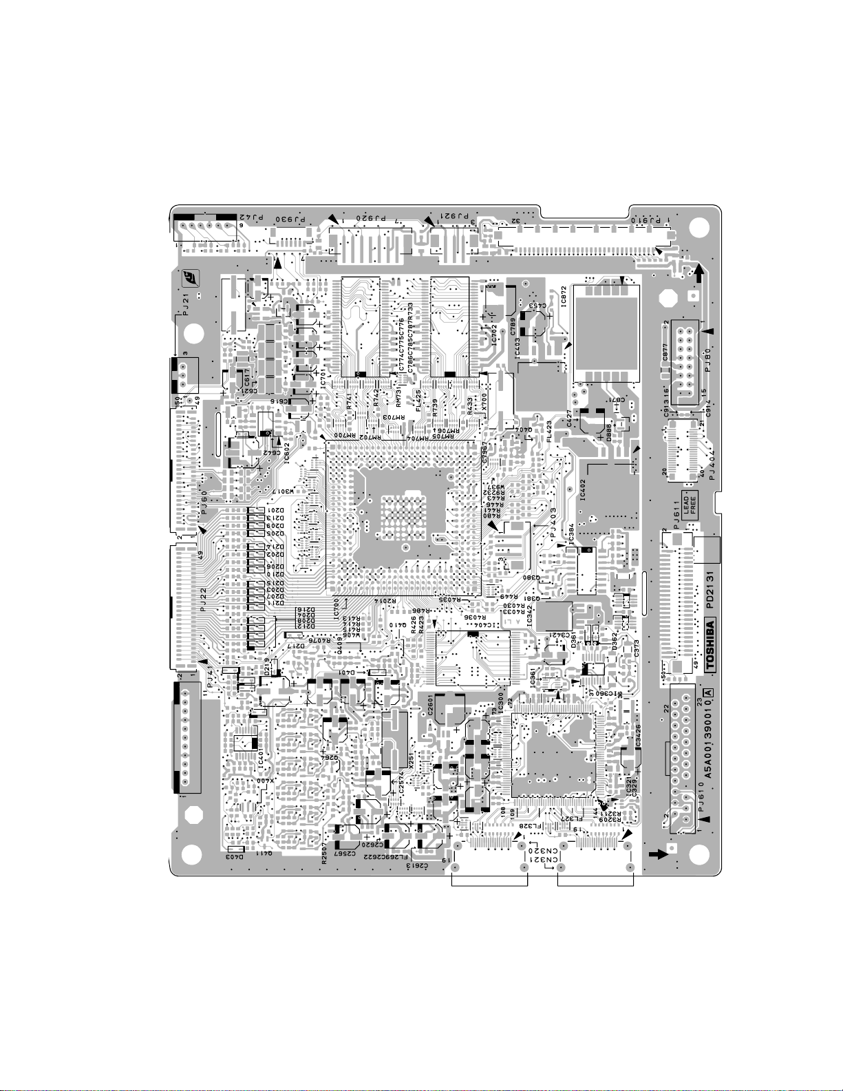
TOP (COMPONENT) SIDE
SIGNAL BOARD PD2222D1 (U101)
-
22
- -
21
-
PV01
R
R
CC02
CC04
CC02
CC04
RC02
RC04
RC02
RC04
L
L
RC03
RC01
CC01CC03
RC01
RC03
CC01
CC03
V
V
RV40
RV340
EXT1
RV40
RV340
EXT2
S
RV370
CV38
CV38
RV370
RV331
RV330
RV331
DV08
DV08
RV330
RV334
RV334
RV333
RV333
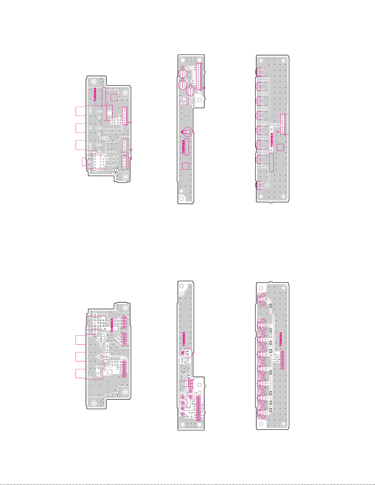
BOTTOM (FOIL) SIDE
AV/AOUT BOARD PD2239A1 (U105A)
RV60
RV60
RV59
RV59
CR
DV01
DV01
CB
DV02
DV02
Y
DV03
DV03
EXT4
R
CC14
RC11
RC11
HDMI-1
23547874
PV02
R
R266
L
R265
R265
R264 R266
R264
L
CC14
DS-1107A
PV03
CR
R
CC05
CC05
RC06
RC06
RC05
RC05
EXT4
DV04
CC07
CC07
R288
DV04
R288
RC08
CB
CC06
CC06
Y
RC08
L
DV05
R287
R287
DV05
DV06
DV06
CC08
RC07
RC07
CC08
EXT5
R286
R286
EXT5
CC15
CC15
RC12
RC12
HDMI-1
R6634
R6636
R6633
R6635
C6607
C6606
C6607
C6606
C6603
C6615
C6604
C6603
C6604
R6623
R6624
R6623
R6624
R6627
R6628
R690
R690
Q660
C6616
R6634
R6633
R6635
C6616
C6615
R6636
R6659
R6657
R6659
R6657
R6627
R6628
R6658
R6660
R6658
C6601
R6660
R6620
C6601
R6625
R6620
R6625
R6622
R6626
C6602
R6626
C6602
R6622
NC
12
GND
ACDETECT
5V-3
5V-3
GND
GND
NC
9V-1
P803B
NC
5V-1
GND
1
Q664
R6605
R6605
Q664
Q665
Q665
R685
R685
+
D678
D678
C690
R692
R683
R691
C685
R692
C685
R691
R683
Q660
Q661
D676
R680
R664
R681
C669
R6603
D680
R6603
D680
D676
R6606
R6606
C691
Q672
R686
Q673
Q673
R686
Q661
C664
R681
R680
R664
C669
C691
C692
C692
R676
R676
Q672
Q671
Q671
R673
C665
R673
R672
C663
C662
C663
C662
R677
R677
R672
C670
C671
D670
C674
C674
D671
+
+
1
2
Q670
D671
D607
C684
C677
R684
R6604
C684
R684
C677
R6604
Q670A
PV05
R
CC11
CC11
LC01
LC01
-
24
L
LC02
CC12
LC02
CC12
V
DV07
DV07
MONITOR OUT
R6615
R6615
R6617
R6617
Q653
R658
R658
R6614
R6614
R6616
R6616
Q652
Q652 Q653
R657
R657
Q651
+
Q651
R656
R659
RV377
RV377
C666
R674
R674
R670
R670
C660
R675
R675
R671
C661
R671
C667
D670
R678
D674
D674
R678
12
D607
D675
D675
R679
R679
C679
C679
R659
RV376
RV376
R656
RV76
RV76
CV72
+
+
CV68
++
C678
C678
7
C656
1
PV25A
CV74
+
RV56
RV55
RV56
RV55
GRV76
LV43
GRV76
LV43
C681
+
P602A
5
C682
+
61
P804B
C680
+
1
TUNER GND
TUNER GND
R_E3
L_E3
GND
V_E3
GND
1
5V-2
GND
9V1
DE99
3
RB577
RB577
RB578
RB578
GND_AUDIO
L_OUT
R_OUT
GND_AUDIO
NC
GND
NC
SOUND GND
SOUND GND
26V
26V
PJ21A
RV44
RV44
RV43
RV43
RV42
RV42
RV41
RV41
- -
23
-
RV58
RV58
RV57
RV57
-1
PD2239
TOP (COMPONENT) SIDE
AV/AOUT BOARD PD2239A1 (U105A)
PV01
SW
G
G
EXT1
V
L
R
LV201
LV202
LV201
LV202
LV200
LV200
Y
C
G
R
EXT2
V
L
R
HDMI-1
EXT4
PV02
Y
CB
CR
23590317
5
6
7
8
+
1
26V
C680
Q670A
2
1
+
+
C673
C673
C671
C690
D672
1
Q6600
8
LV204
LV204
LV205
LV205
HDMI-1
L
1
EXT4
L
3
R
4
C670
+
C664
C675
C675
1
GND
5V-1
NC
9V-1
NC
GND
P803B
GND
5V-3
5V-3
ACDETECT
GND
NC
12
C6600
C6600
D672
R6629
R6629
C6605
C6605
16
Q6600
R6638
9
R6638
Q6603
Q6603
Q6604
Q6604
R6639
R6639
LV207
LV207
LV203
LV208
LV203
LV206
LV208
LV206
PV03 PV05
EXT5
Y
6
EXT5
L
CB
7
3
R
CR
8
4
C667
C665
C666
MONITOR OUT
C682
+
+
12
Q670
11
C681
C661
+
+
C660
CV68
+
+
QV16
QV16
CV76
CV76
+
CV72
LV284
LV284
+
V
L
R
26V
SOUND GND
SOUND GND
P804B
6
5
P602A
1
QB517
CB512
CB512
LV209
LV209
1
CV74
GND
V_E3
GND
L_E3
PV25A
R_E3
TUNER GND
TUNER GND
7
C656
NC
GND
NC
GND_AUDIO
R_OUT
L_OUT
9
16
QB517
GND_AUDIO
50
-
30
PJ60A
PJ60A
20
10
1
5040
30
PJ22A
PJ22A
20
10
1
8
1
3
RB576
RB576
RB575
RB575
9V1
DE99
GND
5V-2
1
PJ21A
26
- -
25
-
-2
23590317
PD2239
LV121
LV121
PV60
TOP (COMPONENT) SIDE
R693
R695
R695
R694
R693
C605
R694
R689
C606
R687
R688
R689
R687
R688
CY650
D652
D653
CY650
P661
D653
FRONT AV BOARD PD2239A2 (U105B)
11
CB05
PJ41C
+
1
+
CB01
CB02
+
KB01
7
PV25B
1
P602B
5
R_GND
R_AMP
L_AMP
L_GND
1
C605
1
L_GND
C606
L_SPK
P601
R_SPK
R_GND
4
D652
TOP (COMPONENT) SIDE
LED-RMT BOARD PD2239A3 (U105C)
DB01A
DB01
23590317
TOP (COMPONENT) SIDE
-3
PD2239
KEY-SW BOARD PD2239A4 (U105D)
UP
SA01
SA02
DOWN
VOL-UP
81
SA04 SA03
VOL-DOWN
PJ42
MENU
SA06 SA05
VIDEO
-4
SA08
GUIDE
PD2239
23590317
POWER
SA07
-
28
P661
23547874
DS-1107A
GR604
GR604
RC10
PV60
BOTTOM (FOIL) SIDE
CC10
CC10
RC10
GR605
GR605
RC09
RC09
RV132
RV132
CC13
CC13
RV133
RV133
RV123
RV123
DV121
DV122
CV122
DV121
DV122
CV122
FRONT AV BOARD PD2239A2 (U105B)
RA79
SA07
RA79
P601
11
P602B
5
17 4
PV25B
BOTTOM (FOIL) SIDE
LED-RMT BOARD PD2239A3 (U105C)
23547874
DS-1107A
DB01
DB01A
RB18
RB18
RB15
RB15
QB07
QB07
DB23
DB23
DB22
DB22
DB20
DB20
KB01
CB03
+
CB03
RB09
RB08
++
RB09
1
RB08
CB01
CB02
PJ41C
CB04
CB38
CB04
CB38
RB24
CB05
RB24
RB22
RB22
11
BOTTOM (FOIL) SIDE
KEY-SW BOARD PD2239A4 (U105D)
23547874
GUIDEVIDEOMENUVOL-DOWN
SA08
RA76 RA78
DS-1107A
RA76
SA06
RA78
RA77
RA77
21
SA05
345
PJ42
6
7
8
RA71
SA04
RA71 RA72 RA73
VOL-UP
SA03
RA72RA73
DOWN
SA02
RA74
UP POWER
RA74
SA01
- -
27
-
PODFAN_STOP
SOUND GND
26V
SOUND GND
26V
GND
P804A
1
234
5
6
RE29
RE26
PJ63A
CE25
32V
1
+
GND
2
BE
20V
3
4
20V
5
NC
GND
6VD
GND
3.3VD-b
3.3VD-a
RE28
QE25
RE27
5
DE72
1
PJ62A
CE32
CE72
+
BOTTOM (FOIL) SIDE
13
16
LE31
CE31
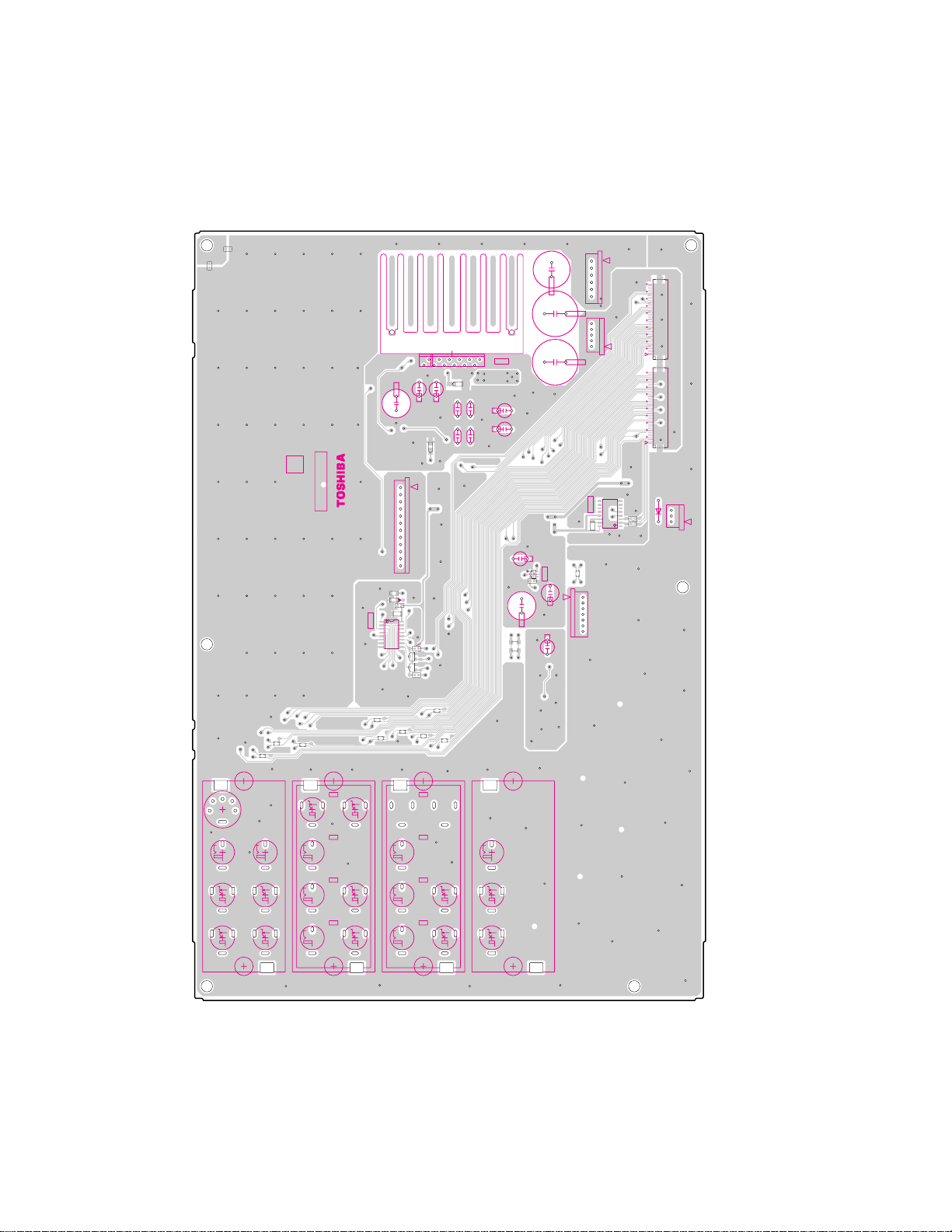
LOWB BOARD PD2202F1 (U803)
CCP-6400 23547851
DE08
DE09
3
P818
+
RE70
TCI-A7S D 94V-0
QE70
13
11
16
LE71
CE71
+
RE85
DE86
QE85
E
B
+
DE05
CE85
DE85
CE08
+
+
DE04
RE86
RE09
RE08
RE05
1
1
2
2
P819
VCC
VCC
GND
GND
FAN-
S_FAN
FAN-
9V-1
9V-2
ACDETECT
5V-3
5V-3
GND
GND
GND
NC
P803A
10
11
12
CE03
B
QE26
E
CE12
+
CE10
+
CE11
LE10
3
5
1
QE10
QE10A
DE71
RE73
RE33
RE17
+
DE31
DE32
B
RE30
QE30
5
11
RE74
1
5
CE70
+
DE88
E
RE87
QE86
B
DE87
DE07
RE06
CE05
1
3
DE06
VCC
FAN-
S_FAN
QE15
RE10
4
2
RE11
B
E
QE11
RE16
B
QE04
RE15
RE34
1
CE30
+
LE30
LE70
F630mAL 250V
FE20
+
DE89
CE86
CE87
+
FAN-VCC
DE10
RE07
3
2
1
2
P820
VCC
GND
GND
FAN-
S_FAN
15
5V-1
32V
GND
16
1
2
3456789
RE13
CE17
+
CE15
+
CE16
5
3
1
QE65
4
2
RE03
RE02
B
RE01
RE63
RE04
DE74
DE61
QE71
EE
DE62
CE62
LE62
++
CE61
QE60
DE20
RE20
1
2
3
P822
DE14
GND
S_FAN
RE14
1
2
3
P821
20V
20V
GND
S_FAN
POWER_SIG
ACDETECT
5V-1
GND
GND
GND
NC
NC
1
2
NC
GND
QE03
3
2
QE01
K
2
12V
GND
DE01
CE67
+
CE65
+
CE66
5
4
RE66
BE
A
CE63
3
4
PJ80A
STOP_FAN
POWTV
POWDB
RE19
E
RE18
B
26V
11
QE02
DE02
10
26V
9
SOUND GND
8
SOUND GND
7
PROTECT
ACDETECT
6
5
POWER_SIG
4
POWER
3
5V-1
RE65
GND
2
1
32V
P809A
QE66
PP80
PP81
LE60
DE60
CE60
+
RE61
5
CE64
LE61
RE60
EB
QE61
NC
DE03
E
B
RE12
1
E
1
QE60A
-
30
- -
6
789
101211
435
12V
12V
GND
P807A
12V
12V
GND
GND
GND
GND
29
-
SCHEMATIC DIAGRAM
MODEL : 42DPC85
WARNING : BEFORE SERVICING THIS CHASSIS, READ THE "SERVICE SAFETY PRECAUTIONS" ON PAG E 3 OF
THIS MANUAL.
CAUTION : The international hazard symbols " " in the schematic diagram and the parts list designate components
which have special characteristics important for safety and should be replaced only with types identical to those in the
original circuit or specified in the parts list. The mounting position of replacements is to be identical with originals. Before
replacing any
model. Do not degrade the safety of the receiver through improper servicing.
NOTE:
1. RESISTOR Resistance is shown in ohm [K = 1.000, M = 1.000.000]. All resistors are 1/6W and 5%
2. CAPACITOR Unless otherwise noted in schematic, all capacitor values less than 1 are expressed in
3. The parts indicated with " * " have special characteristics, and should be replaced with identical parts only.
4. Voltages read with DIGITAL MULTI-METER from point indicated to chassing ground, using a color bar signal with all
controls at normal, line voltage 220 volts.
5. Waveforms are taken
6. Voltage reading shown are nominal values and may vary ±20% except H.V.
of these components, read carefully the SERVICE SAFETY PRECAUTIONS on the MANUAL for this
tolerance carbon resistor, unless otherwise noted as the following marks.
1/2R = Metal or Metal oxide of 1/2 watt 1/2S = Carbon compsistion of 1/2 watt
1RF = Fuse resistor of 1 watt 1
K = ±10% G = ±2% F = ± 1%
?F, and the values more than 1 in pF.
All capacitors are ceramic 50V, unless otherwise noted as the following marks.
Electolytic
receiving color bar signal with enough sensitivity.
capacitor Mylar capacitor
0W = Cement of 10 watt
-
31
-

SCHEMATIC DIAGRAM STRUCTURE:
AV/AOUT CONNECTOR [SHEET-1/4] ........ 1/47
AV-TERMINAL [SHEET-2/4] ........ 2/47
A-OUT [SHEET-3/4] ........ 3/47
EXPANDER FOR PDP [SHEET-4/4] ........ 4/47
FRONT-AV ........................................................................................................................................................... 5/47
IR LED ................................................................................................................................................................ 6/47
KEY ..................................................................................................................................................................... 7/47
LOWB .................................................................................................................................................................. 8/47
SIGNAL ANALOG IN [SHEET-200] ........ 9/47
D IN A [SHEET-300] ...... 10/47
D IN B [SHEET-301] ...... 11/47
HDMI (
Link, I2C) [SHEET-302] ...... 12/47
HDMI Rx#2 (Video/Audio) [SHEET-303] ...... 13/47
HDMI Rx#3 (PWR,Audio) [SHEET-304] ...... 14/47
HDMI AUDIO PLL [SHEET-305] ...... 15/47
HDMI AUDIO DAC [SHEET-306] ...... 16/47
HDMI AUDIO OUT [SHEET-307] ...... 17/47
HDMI CONTROLLER [SHEET-308] ...... 18/47
EEPROM1 [SHEET-309] ...... 19/47
EEPROM2 [SHEET-310] ...... 20/47
MICRO I/O [SHEET-
400] ...... 21/47
OCM MEMORY I/F [SHEET-401] ...... 22/47
FLASH MEMORY [SHEET-402] ...... 23/47
SYNC SEPA [SHEET-403] ...... 24/47
E2P OTHER [SHEET-404]...... 25/47
STD-BY MICOR [SHEET-405] ...... 26/47
CORTEZ REG 1 [SHEET-406] ...... 27/47
CORTEZ REG 2 [SHEET-407] ...... 28/47
CORTEZ REG 3 [SHEET-408] ...... 29/47
BOOT CONFIG [SHEET-409] ...... 30/47
SERVICE CONN
ECTOR [SHEET-410] ...... 31/47
I2C Switch [SHEET-411] ...... 32/47
STBY MICRO for DVD internal [SHEET-412] ...... 33/47
DVD 10pin connector [SHEET-413] ...... 34/47
I2C Level shift [SHEET-414] ...... 35/47
AUDIO [SHEET-600] ...... 36/47
AUDIO MSP [SHEET-601] ...... 37/47
CORTEZ 1 [SHEET-700] ...... 38/47
CORTEZ 2 [SHEET-701] ...... 39/47
DDR I/F [SHEET-702] ...... 40/47
DDR
SDRAM [SHEET-703] ...... 41/47
DDR TERMINATION [SHEET-704] ...... 42/47
DCDC CONV. [SHEET-802] ...... 43/47
LVDS OUT [SHEET-900] ...... 44/47
LVDS OUT(SHARP LCD) [SHEET-901] ...... 45/47
Powe r Connector and Dimming [SHEET-902] ...... 46/47
LVDS Powe r and Others [SHEET-903] ...... 47/47
-
32
-
 Loading...