

Toshiba 42DPC85 Service Manual

SERVICE MANUAL
DOCUMENT CREATED IN JAPAN, Sept., 2005
Revision 1
Plasma Monitor
42DPC85
FILE NO. 020-200521
TOSHIBA CORPORATION 2005
-
1
-
Published in Japan, Sep. 2005 (YC)

TABLE OF CONTENTS
SERVICE SAFETY PRECAUTIONS .................................................................................................................................... 3
SERVICE MODE .................................................................................................................................................................. 5
LAYOUT OF MAJOR BOARDS .......................................................................................................................................... 10
MECHANICAL DISASSEMBLY .......................................................................................................................................... 11
EXPLODED VIEW .............................................................................................................................................................. 13
PACKING DISASSEMBLY ................................................................................................................................................. 15
CHASSIS AND CABINET REPLACEMENT PARTS LIST ................................................................................................. 16
PC BOARDS TOP & BOTTOM VIEW ................................................................................................................................ 19
CIRCUIT BLOCK DIAGRAM .............................................................................................................................................. 33
APPENDIX:
SCHEMATIC DIAGRAM
-
2
-
GENERAL ADJUSTMENTS
SPECIFIC INFORMATIONS
SERVICE SAFETY PRECAUTIONS
• The caution items shown here describe major safety issues and should always be observed.
• The meanings of the various indications are as follows.
WARNING
CAUTION
* Physical damage means major damage to a home, furnishings and other possessions.
Examples of marks
SHOCK HAZARD
PROHIBIT DISASSEM-
BLING
UNPULUG
Indicates a hypothetical situation in which service personnel and nearby third parties, or even
end users due to a product defect after the service operation is completed, could possibly be in
danger of injury or even death in the event of operational error.
Indicates a hypothetical situation in which service personnel and nearby third parties, or even
end users after the service operation is completed, could possibly be in danger of injury, or
where there could be physical damage in the event of operational error.
The" indicates caution (including danger and warning).
"
The actual meaning of this caution is indicated inside the
The example shown to the left indicates the danger of "electrical shock".
The
indicates a forbidden action.
The actual meaning of this caution is indicated inside the
The example shown to the left indicates that disassembly is forbidden.
The
-
indicates a forced action (an action that must be performed).
The actual meaning of this forced action is indicated by
The example shown to the left indicates that the power plug must be disconnected.
or nearby illustrations or text.
or nearby illustrations or text.
-
or nearby illustrations or text.
-
3
-
KEEP CHILDREN
AWAY
UNPULUG
SHOCK HAZARD
USE SPECIFIED
PARTS
CAUTION FOR
WIRING
CAUTION FOR
ASSEMBLING /
WIRING
WARNING
• Always advise users to keep children away.
There is danger of injury to children from tools, disassembled products, etc.
• Always disconnect the power plug before starting work whenever power is not required.
Failure to disconnect the power plug before starting work can result in electrical shock.
• Depending on the model, use an insulation transformer or wear gloves when servicing with the
power on, and disconnect the power plug to avoid electrical shock when replacing parts.
In some cases, alternating current is also impressed in the chassis, so electrical shock is possible if the chassis is contacted with the power on.
• Always use the replacement parts specified for the particular model when making repairs.
The parts used in products have the necessary safety characteristics such as inflammability,
voltage resistance, etc.; therefore, use only replacement parts that have these same characteristics.
Use only the specified parts when the
• Parts mounting and routing of the wiring should be the same as that used originally.
For safety purposes, insulating materials such as tubing or tape is sometimes used and printed
circuit boards are sometimes mounted floating.
Also make sure that wiring is routed and clamped to avoid parts that generate heat and which
use high voltage. Always follow the original scheme.
• After a repair has been completed, reassemble all disassembled parts, and route and reconnect the wiring, in accordance with the original scheme.
Do not allow internal wiring to be pinched by cabinets, panels, etc.
Any error in reassembly or wiring can result in electrical leakage, flame, etc., and may be
hazardous.
mark is included in a circuit diagram or parts list.
CHECK INSULATION
RESISTANCE
PROHIBIT
REMODELING
• After completing the work, disconnect the power plug from the outlet, remove the antenna, turn
on the power switch. Then, use a 500V insulation resistance meter to check the insulation
resistance of the antenna terminal, other metallic parts and between the prongs of the power
plug to make sure that the insulation resistance is 1M 1 or more.
The set will require inspection and repair if the insulation resistance is below this value.
• Never remodel the product in any way.
Remodeling can result in improper operation, malfunction, or electrical leakage and flame,
which may be hazardous
-
4
-
SERVICE MODE
Recall
Recall
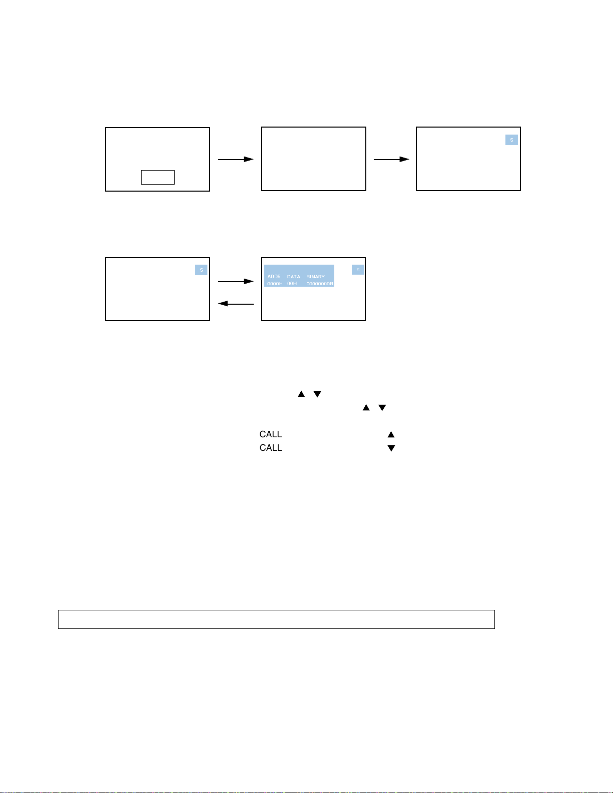
1. ENTERING SERVICE MODE
1) Press MUTE button twice on 2) Press MUTE button again and 3) While pressing the MUTE button,
Remote Control. keep pressing. press MENU button on TV set.
MUTE
2. DISPLAYING THE ADJUSTMENT MENU
1) Press MENU button on Remote Control.
Service mode Adjustment mode
Press
Press
3. KEY FUNCTION IN THE SERVICE MODE
The following key entry during display of adjustment menu provides special functions.
(Service mode display)
Test signal selection : TV/VIDEO button (on Remote)
Selection of the adjustment items : Channel
Change of the data value : Volume W / X (on TV) or
Adjustment menu mode ON/OFF : MENU button (on Remote)
Initialization of the memory : CALL + Channel button on TV ( )
Reset the count of operating protect circuit to “00” :
“RCUT” selection : 1 button
“GCUT” selection : 2 button
“BCUT” selection : 3 button
“CNTX” selection : 4 button
“COLC” selection : 5 button
“UVTT” selection : 6 button
Automatic A/D Adjustment(PC, Component) : 7 button
Self diagnostic display ON/OFF : 9 button
CAUTION : Never try to perform initialization unless you have changed the memory IC.
CALL + Channel button on TV ( )
/ (on TV or Remote)
-----
Color thickness correction
note: Displayed differently as shown below, depending
on the setting of the receiving color system.
COLP (PAL)
COLC (NTSC)
COLS (SECAM)
/ (on Remote)
-
7
-
4. SELECTING THE ADJUSTING ITEMS
Recall
1) Every pressing of CHANNEL
button for reverse order)
(
5. ADJUSTING THE DATA
1) Pressing of VOLUME W / X , / button will change the value of data in the range from 00H to FFH. The
variable range depends on the adjusting item.
6. EXIT FROM SERVICE MODE
1) Pressing POWER button to turn off the TV once.
INITIALIZATION OF MEMORY DATA
After replacing EEPROM IC, the following initialization is required.
1. Enter the service mode, then select any register item.
2. Press and hold the CALL button on the Remote, then press the CHANNEL
EEPROM IC has been completed.
3. Check the picture carefully. If necessary, adjust any adjustment item above.
Perform “Auto tune” on the owner’s manual.
CAUTION: Never attempt to initialize the data unless EEPROM IC has been replaced.
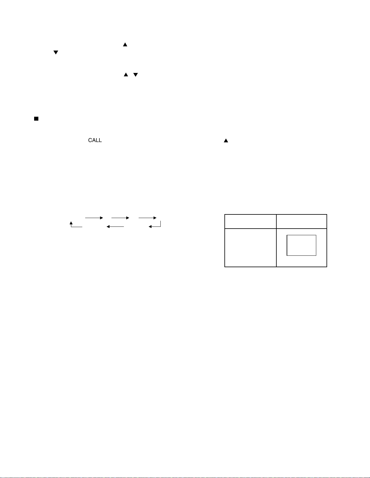
7. TEST SIGNAL SELECTION
1) Every pressing of TV/VIDEO button on the Remote Control changes the built-in test patterns on screen as described
below in SERVICE MODE.
button in the service mode changes the adjustment items in the order of table-2.
button on the TV. The initialization of
R
All BlackAll White
BSignal off G
Signals Picture
• Red raster
• Green raster
• Blue raster
• All Black
• All White
-
8
-
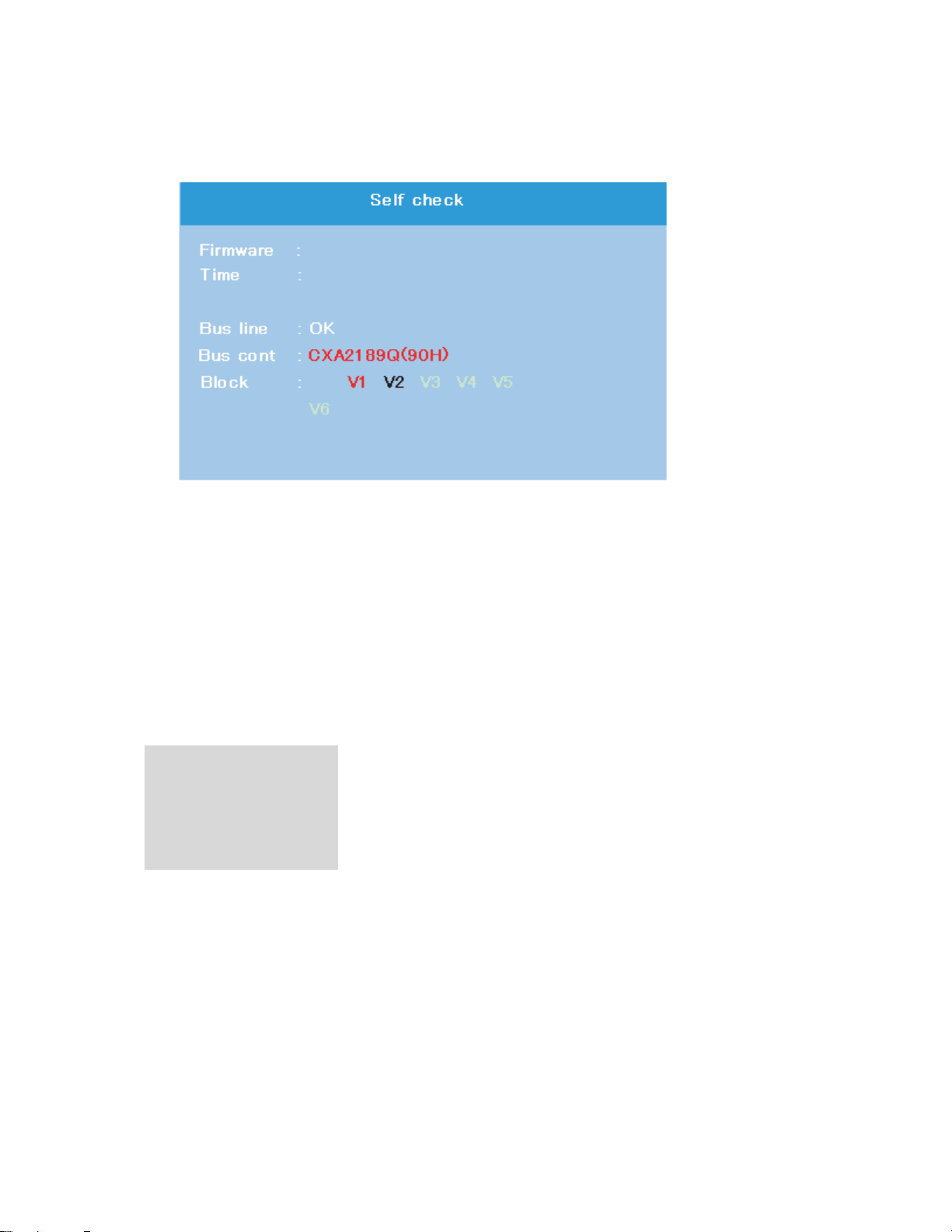
8. SELF DIAGNOSTIC FUNCTION
000000
DPC85_0100
1) Press “9” button on Remote Control during display of adjustment menu in the service mode.
The diagnosis will begin to check if interface among IC’s is executed properly.
2) During diagnosis, the following displays are shown.
M
N
O
P
Q
M Firmware :
Version information of microprocessor
In case of file name : DPC85 and Version : 0100 indicates[DPC85_0100].
N Time : Total hour of turn the TV on. (Unit : H)
O Bus line : --"OK" is normal
"SCL-GND"(Red indication) : SCL-GND short circuit
"SDA-GND"(Red indication) : SDA-GND short circuit
"SCL-SDA"(Red indication) : SCL-SDA short circuit
P Bus cont : --- "OK" is normal.
NG is abnormal(Red indication), when type name of semiconductor indicates.
Q Block
V1 : VIDEO 1 input mode
V2 : VIDEO 2 input mode
V3 : VIDEO 3 input mode
V4 : ColorStream 1 IN
V5 : ColorStream 2 IN
V6 : HDMI A/V IN
-
7
-
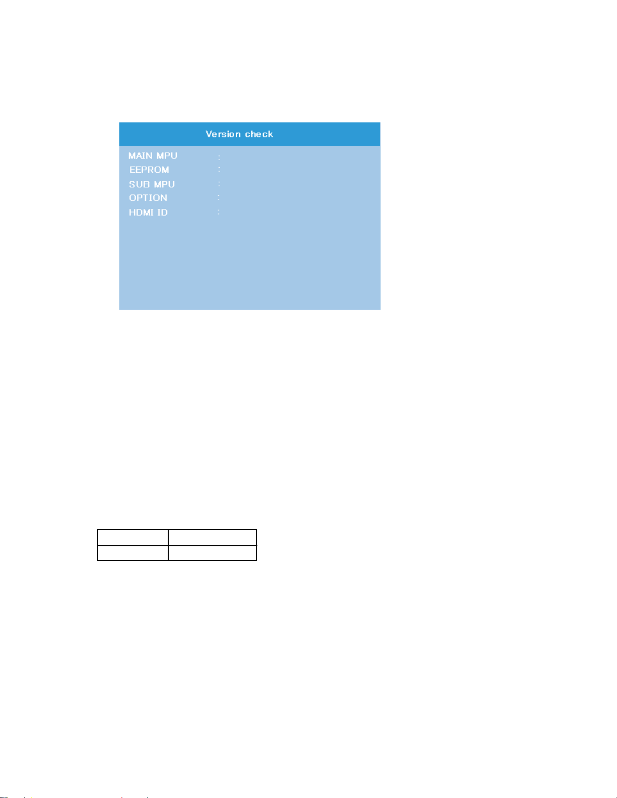
9. VERSION CHECK MODE
DPC85_0100(U15)
01
36
24 00 01 57 00 00
00000155
LG−42
1) Press “9” button twice on Remote Control during display of adjustment menu in the service mode. The version of main
MPU will begin to check.
2) During Version Check, the following displays are shown.
M
N
O
P
Q
R
M
MAIN MPU :
Version information of microprocessor
In case of file name : DPC85, Version 0100 for Code Program Version
and (U15) for OSD Version indicates [DPC85_0100(U15)]
N EEPROM :
Version information of EEPROM : Display 1 byte data.
O SUB MPU :
Version information of SUB MPU : Display 1 byte data.
P OPTION :
Option information : Display six numbers of 1 byte data.
Q HDMI ID :
HDMI ID information : Display 4 byte data.
R PDP Panel Vender information display
The following Panel Vender and screen size are displayed.
Panel Vender Screen Size(Inch)
LG -42
Example : LG-42 indicates that vender is LG and Screen Size is 42 inch.
-
8
-
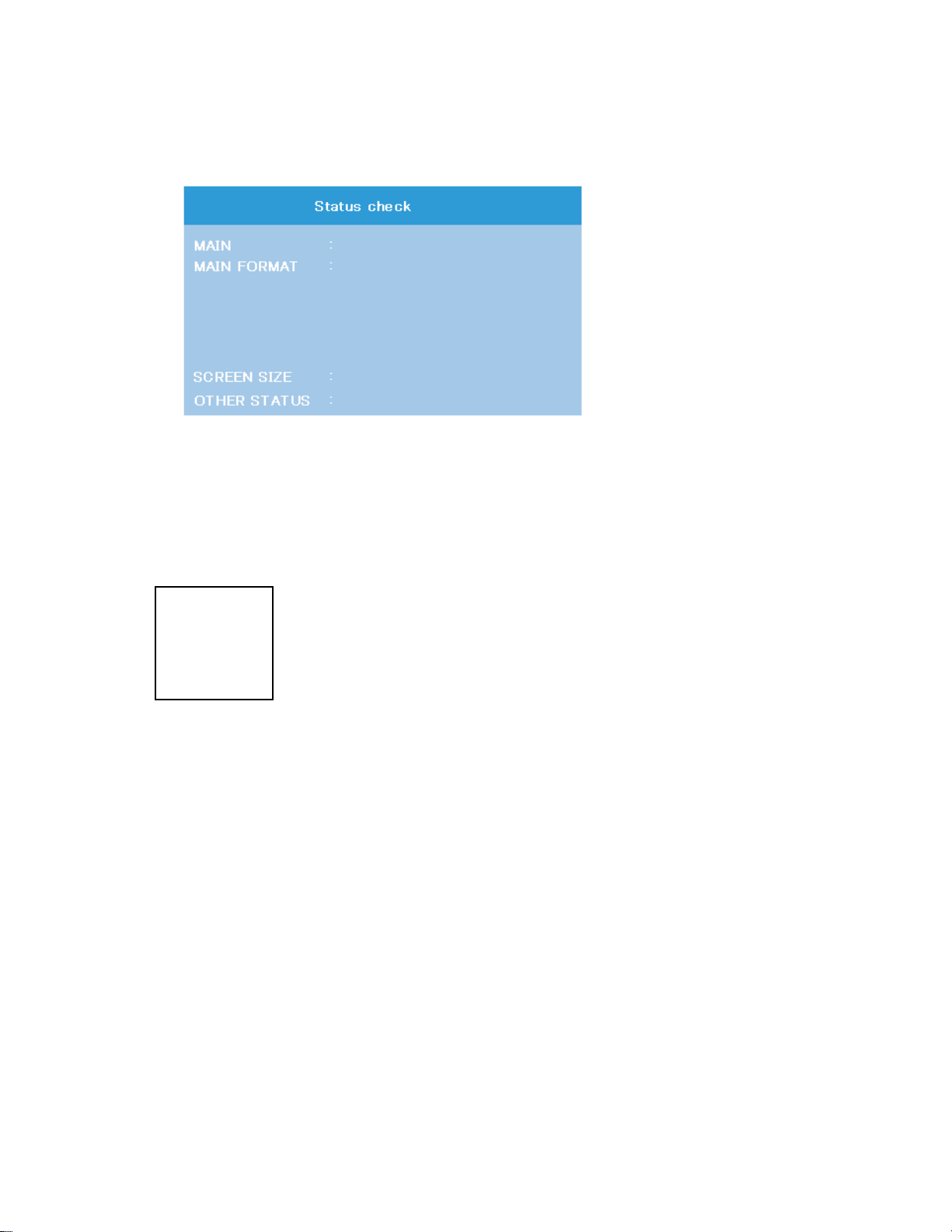
10. STATUS CHECK MODE
EXT1
480i
NATURAL
0000 0000 0000
1) Press “9” button thrice on Remote Control during display of adjustment menu in the service mode. The status of this
model will begin to check.
2) During Status Check, the following displays are shown.
M
N
O
P
M MAIN :
Main source information :
Display RF position number (0 - 99) on the main screen, or Input Source (EXT1/2/3/HDMI etc.)
N MAIN FORMAT :
Display Video and PC format information
O SCREEN SIZE :
Display the screen size as follows.
Theater Wide 1
Theater Wide 2
Theater Wide 3
FULL
NATURAL
P
OTHER STATUS :
Other status information : Display three numbers of 2 byte data.
-
9
-
 Loading...