

Page 1
SERVICE MANUAL
LCD Color Television
42AV554D
This model is classified as a green product (*1), as indicated by the underlined serial number.
Ver. 2.00
This Service Manual describes replacement parts for the green product. When repairing this
green product, use the part(s) described in this manual and lead-free solder (*2).
For (*1) and (*2), refer to GREEN PRODUCT PROCUREMENT and LEAD-FREE
SOLDER.
© TOSHIBA CORPORATION
Page 2

IMPORTANT NOTICE
WARNING:
You are requested that you shall not modify or alter the information or data
provided herein without prior written consent by Toshiba. Toshiba shall not
be liable to anybody for any damages, losses, expenses or costs, if any,
incurred in connection with or as a result of such modification or alteration.
THE INFORMATION OR DATA HEREIN SHALL BE PROVIDED "AS IS"
WITHOUT ANY WARRANTY OF ANY KIND, EITHER EXPRESS OR IMPLIED
WARRANTY OF MERCHANTABILITY AND FITNESS FOR A PARTICULAR
PURPOSE.
Toshiba shall not be liable for any damages, losses, expenses or costs, if
any, incurred in connection with or as a result of use of any information or
data provided herein.
Page 3

GREEN PRODUCT PROCUREMENT
p
p
The EC is actively promoting the WEEE & RoHS Directives that define standards for
recycling and reuse of Waste Electrical and Electronic Equipment and for the Restriction of
the use of certain Hazardous Substances. From July 1, 2006, the RoHS Directive will
rohibit any marketing of new products containing the restricted substances.
Increasing attention is given to issues related to the global environmental. Toshiba
Corporation recognizes environmental protection as a key management tasks, and is doing its
utmost to enhance and improve the quality and scope of its environmental activities. In line
with this, Toshiba proactively promotes Green Procurement, and seeks to purchase and use
roducts, parts and materials that have low environmental impacts.
Green procurement of parts is not only confined to manufacture. The same green parts used
in manufacture must also be used as replacement parts.
Page 4

LEAD-FREE SOLDER
p
p
This product is manufactured using lead-free solder as a part of a movement within the
consumer products industry at large to be environmentally responsible. Lead-free solder must
be used in the servicing and repair of this product.
WARNING: This product is manufactured using lead free solder.
DO NOT USE LEAD BASED SOLDER TO REPAIR THIS PRODUCT!
The melting temperature of lead-free solder is higher than that of leaded solder by 86ºF to
104ºF (30ºC to 40ºC). Use of a soldering iron designed for lead-based solders to repair
roduct made with lead-free solder may result in damage to the component and or PCB being
soldered. Great care should be made to ensure high-quality soldering when servicing this
roduct especially when soldering large components, through-hole pins, and on PCBs as the
level of heat required to melt lead-free solder is high.
Page 5

SAFETY INSTRUCTION
WARNING: BEFORE SERVICING THIS CHASSIS, READ THE "SAFETY
PRECAUTION" AND "PRODUCT SAFETY NOTICE" INSTRUCTIONS BELOW.
Safety Precaution
WARNING: SERVICING SHOULD NOT BE ATTEMPTED BY ANYONE
UNFAMILIAR WITH THE NECESSARY PRECAUTIONS ON THIS RECEIVER.
THE FOLLOWING ARE THE NECESSARY PRECAUTIONS TO BE OBSERVED
BEFORE SERVICING THIS CHASSIS.
1. An isolation transformer should be connected in the power line between the receiver
and the AC line before any service is performed on the receiver.
2. Always disconnect the power plug before any disassembling of the product. It may
result in electrical shock.
3. When replacing a chassis in the cabinet, always be certain that all the protective
devices are put back in place, such as nonmetallic control knobs, insulating covers,
shields, isolation resistor-capacitor network, etc.
4. Always keep tools, components of the product, etc away from the children, These items
may cause injury to children.
5. Depending on the model, use an isolation transformer or wear suitable gloves when
servicing with the power on, and disconnect the power plug to avoid electrical shock
when replacing parts. In some cases, alternating current is also impressed in the
chassis, so electrical shock is possible if the chassis is contacted with the power on.
Page 6

6. Always use the replacement parts specified for the particular model when making
repairs. The parts used in products require special safety characteristics such as
inflammability, voltage resistance, etc. therefore, use only replacement parts that have
these same characteristics. Use only the specified parts when the mark is indicated
in the circuit diagram or parts list.
7. Parts mounting and routing dressing of wirings should be the same as that used
originally. For safety purposes, insulating materials such as isolation tube or tape are
sometimes used and printed circuit boards are sometimes mounted floating. Also make
sure that wirings is routed and clamped to avoid parts that generate heat and which use
high voltage. Always follow the manufactured wiring routes / dressings.
8. Always ensure that all internal wirings are in accordance before re-assembling the
external casing after a repairing completed. Do not allow internal wiring to be pinched
by cabinets, panels, etc. Any error in reassembly or wiring can result in electrical
leakage, flame, etc., and may be hazardous.
9. NEVER remodel the product in any way. Remodeling can result in improper operation,
malfunction, or electrical leakage and flame, which may be hazardous.
10. Touch current check. (After completing the work, measure touch current to prevent an
electric shock.)
z Plug the AC cord directly into the AC outlet. Do NOT use an isolation transformer
for this check.
z Connect a measuring network for touch currents between each exposed metallic part
on the set and a good earth ground such as a water pipe.
Annex D
(normative)
Measuring network for TOUCH CURRENTS
Page 7
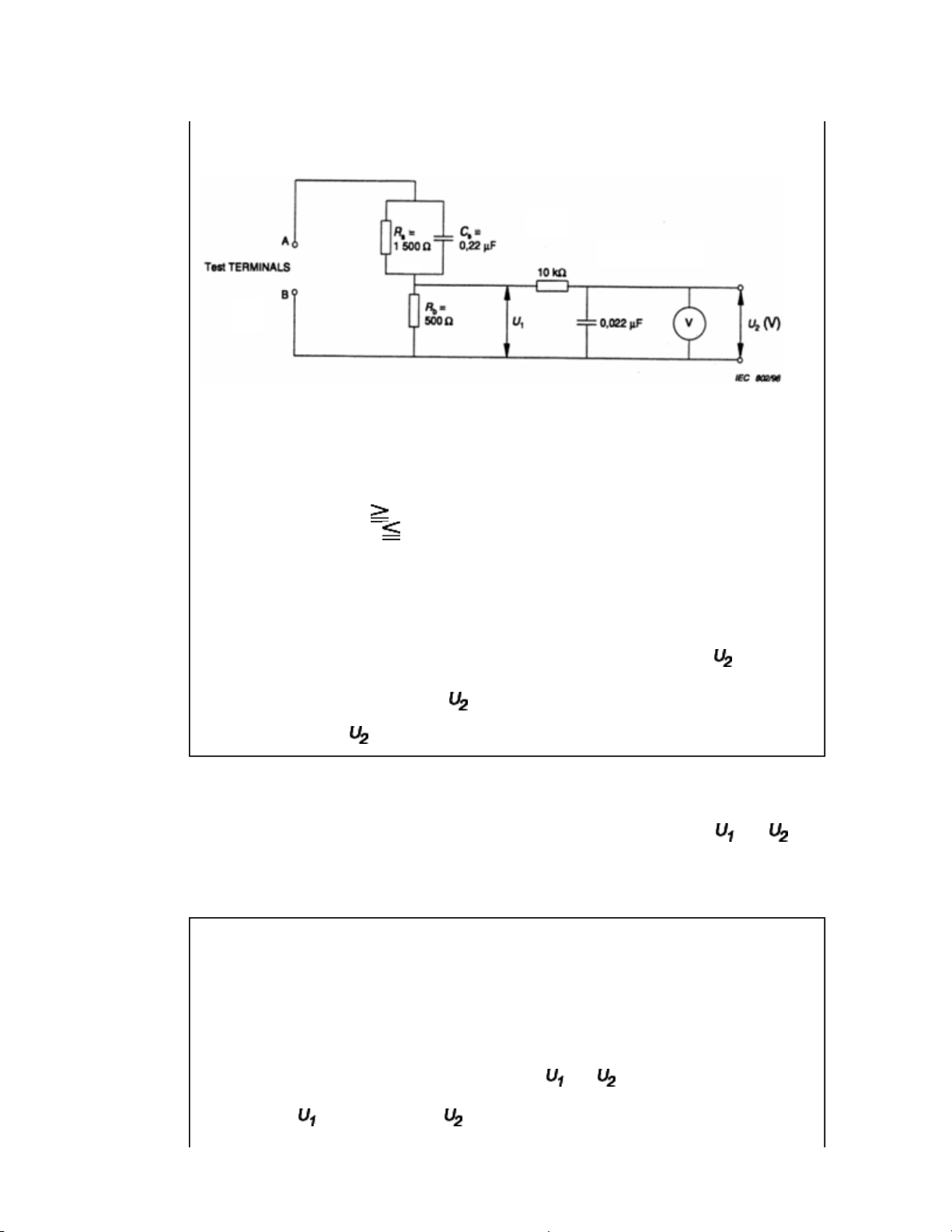
Resistance values in orms (Ω).
V: Voltmeter or oscilloscope
(r.m.s. or peak reading)
Input resistance : 1 MΩ
Input capacitance : 200 pF
Frequency range : 15 Hz to 1 MHz and d.c. respectively
Note: Appropriate measures should be taken to obtain the correct value in case of non
sinusoidal waveforms.
The measuring instrument is calibrated by comparing the frequency factor of with the
solid line in figure F.2 of IEC 60990 at various frequencies. A calibration curve is
constructed showing the deviation of from the ideal curve as a function of frequency.
TOUCH CURRENT = /500 (peak value).
z The potential at any point (TOUCH CURRENT) expressed as voltage and
does not exceed the following value:
The part or contact of a TERMINAL is not HAZARDOUS LIVE if:
a) The open-circuit voltage should not exceed 35 V (peak) a.c. or 60 V d.c. or, if a) is not
met.
b) The measurement of the TOUCH CURRENT shall be carried out in accordance with
IEC 60990, with the measuring network described in Annex D of this standard.
The TOUCH CURRENT expressed as voltages and , does not exceed the
following values:
- for a.c. : = 35 V (peak) and = 0.35 V (peak);
Page 8

- for d.c. : = 1.0 V
Note: The limit values of = 0.35 V (peak) for a.c. and = 1.0 V for d.c. correspond to
the values 0.7 mA (peak) a.c. and 2.0 mA d.c.
Product Safety Notice
Many electrical and mechanical parts in this chassis have special safety-related
characteristics. These characteristics are often passed unnoticed by a visual inspection and
the protection afforded by them cannot necessarily be obtained by using replacement
components rated for higher voltage, wattage, etc. Replacement parts which have these
special safety characteristics are identified in this manual and its supplements; electrical
components having such features are identified by the international hazard symbols on the
schematic diagram and the parts list.
Before replacing any of these components, read the parts list in this manual carefully. The
use of substitute replacement parts which do not have the same safety characteristics as
specified in the parts list may create electrical shock, fire, or other hazards.
Page 9
SAFETY INSTRUCTION
Handling the LCD Module
Safety Precaution
In the event that the screen is damaged or the liquid crystal (fluid) leaks, do not breathe in or
drink this fluid.
Also, never touch this fluid. Such actions could cause toxicity or skin irritation. If this fluid
should enter the mouth, rinse the mouth thoroughly with water. If the fluid should contact the
skin or clothing, wipe off with alcohol, etc., and rinse thoroughly with water. If the fluid
should enter the eyes, immediately rinse the eyes thoroughly with running water.
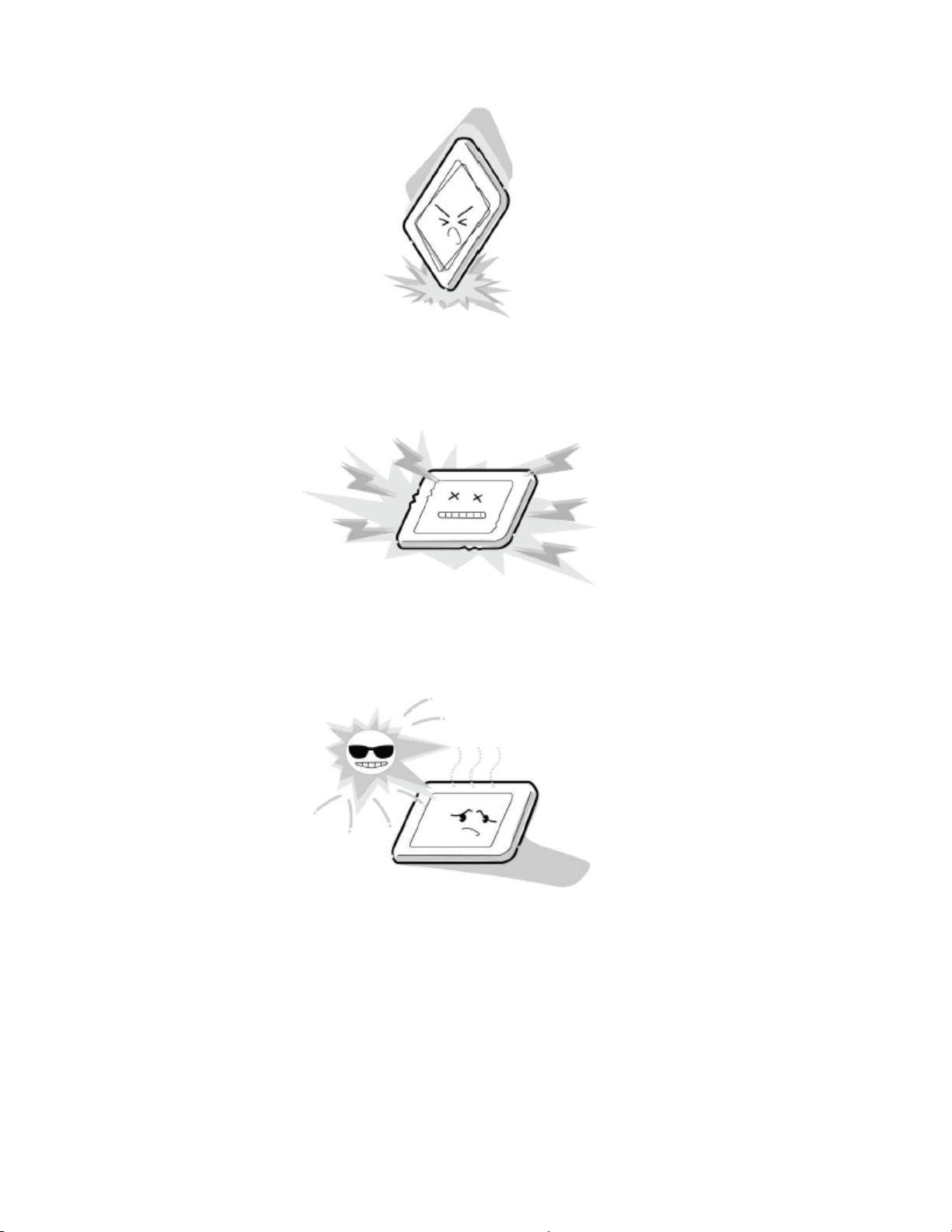
Precautions for Handling the LCD Module
CAUTION: The metal edges of the LCD module are sharp, handle it with
care.
The LCD module can easily be damaged during disassembly or reassembly; therefore,
always observe the following precautions when handling the module.
1. When attaching the LCD module to the LCD cover, position it appropriately and fasten
at the position where the display can be viewed most conveniently.
2. Carefully align the holes at all four corners of the LCD module with the corresponding
holes in the LCD cover and fasten with screws. Do not strongly push on the module
Page 10
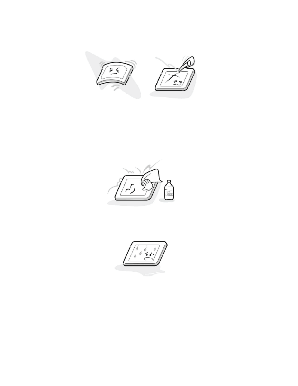
because any impact can adversely affect the performance. Also use caution when
handling the polarized screen because it can easily be damaged.
3. If the panel surface becomes soiled, wipe with cotton or a soft cloth. If this does not
remove the soiling, breathe on the surface and then wipe again.
If the panel surface is extremely solied, use a CRT cleaner as a cleaner. Wipe off the
panel surface by drop the cleaner on the cloth. Do not drop the cleaner on the panel.
Pay attention not to scratch the panel surface.
4. Leaving water or other fluids on the panel screen for an extended period of time can
result in discoloration or stripes. Immediately remove any type of fluid from the screen.
5. Glass is used in the panel, so do not drop or strike with hard objects. Such actions can
damage the panel.
Page 11
6. CMOS-LSI circuitry is used in the LCD module, so avoid damage due to static
electricity. When handling the module, use a wrist ground or anchor ground.
7. Do not expose the LCD module to direct sunlight or strong ultraviolet rays for an
extended period of time.
8. Do not store the LCD module below the temperature conditions described in the
specifications. Failure to do so could result in freezing of the liquid crystal due to cold
air or loss of resilience or other damage.
Page 12
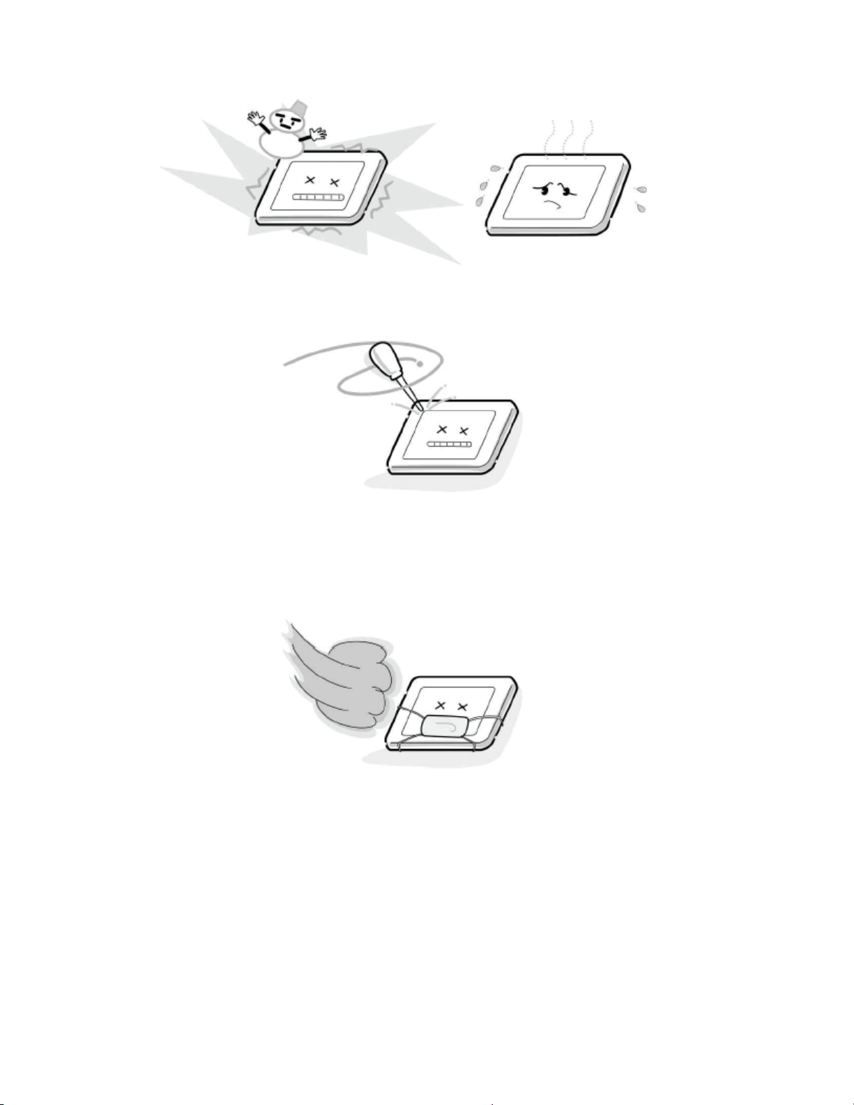
9. Do not disassemble the LCD module. Such actions could result in improper operation.
10. When transporting the LCD module, do not use packing containing epoxy resin
(amine) or silicon resin (alcohol or oxim). The gas generated by these materials can
cause loss of polarity.
Page 13

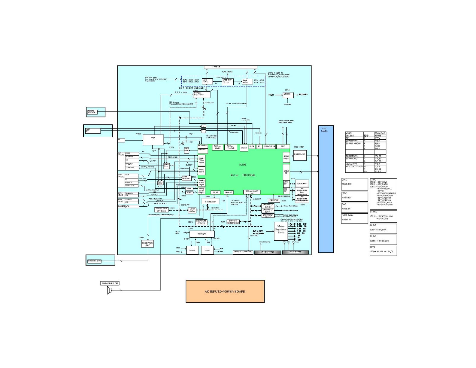
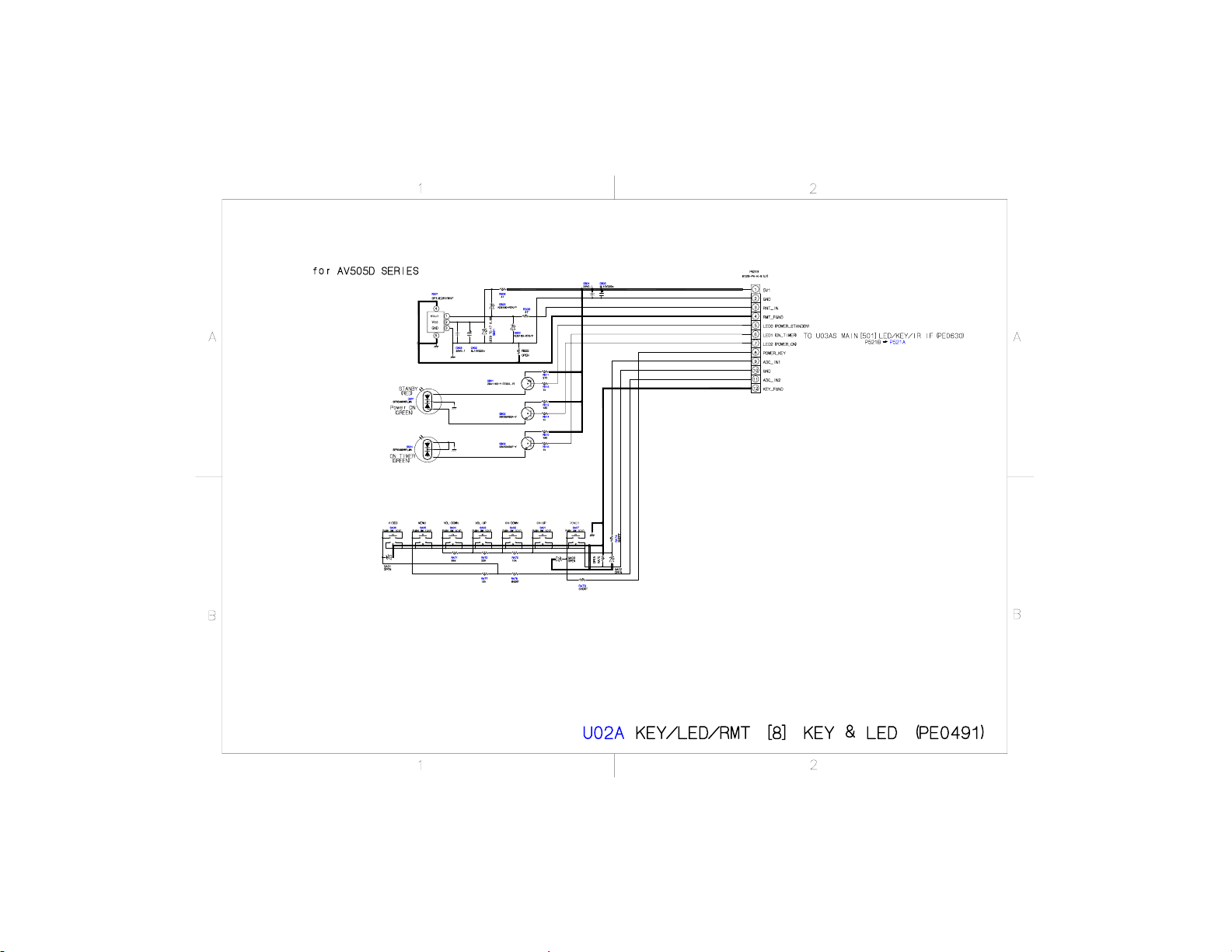
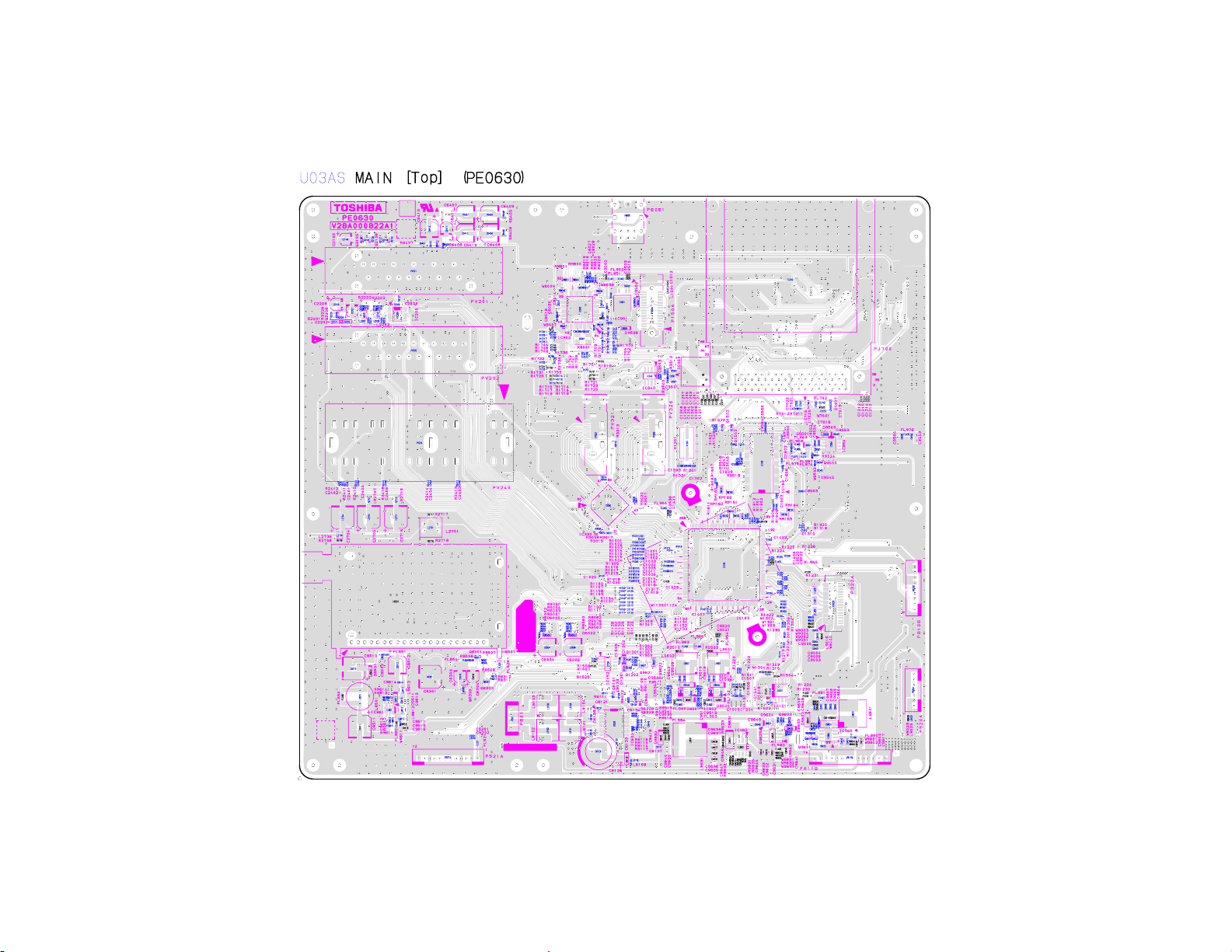
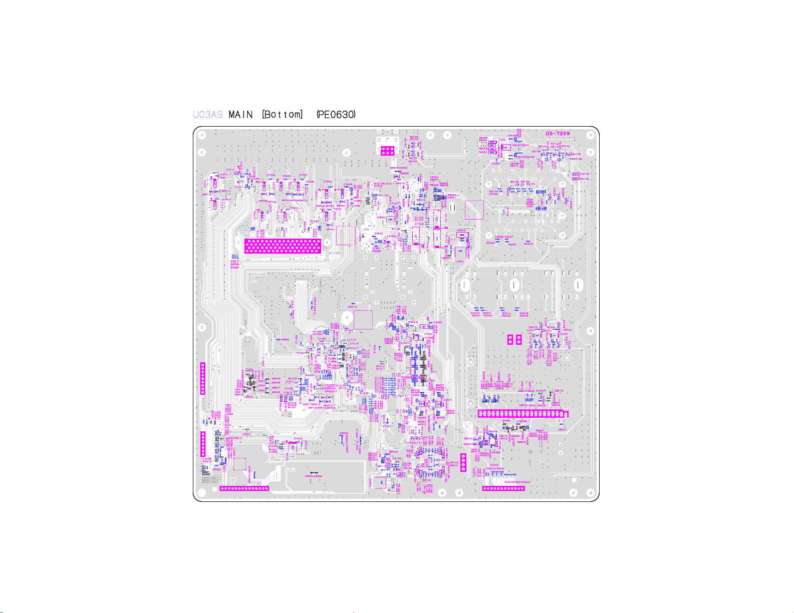
U03A
MAIN
POWER
U02A
KEY/LED/RMT
Page 14
Page 15

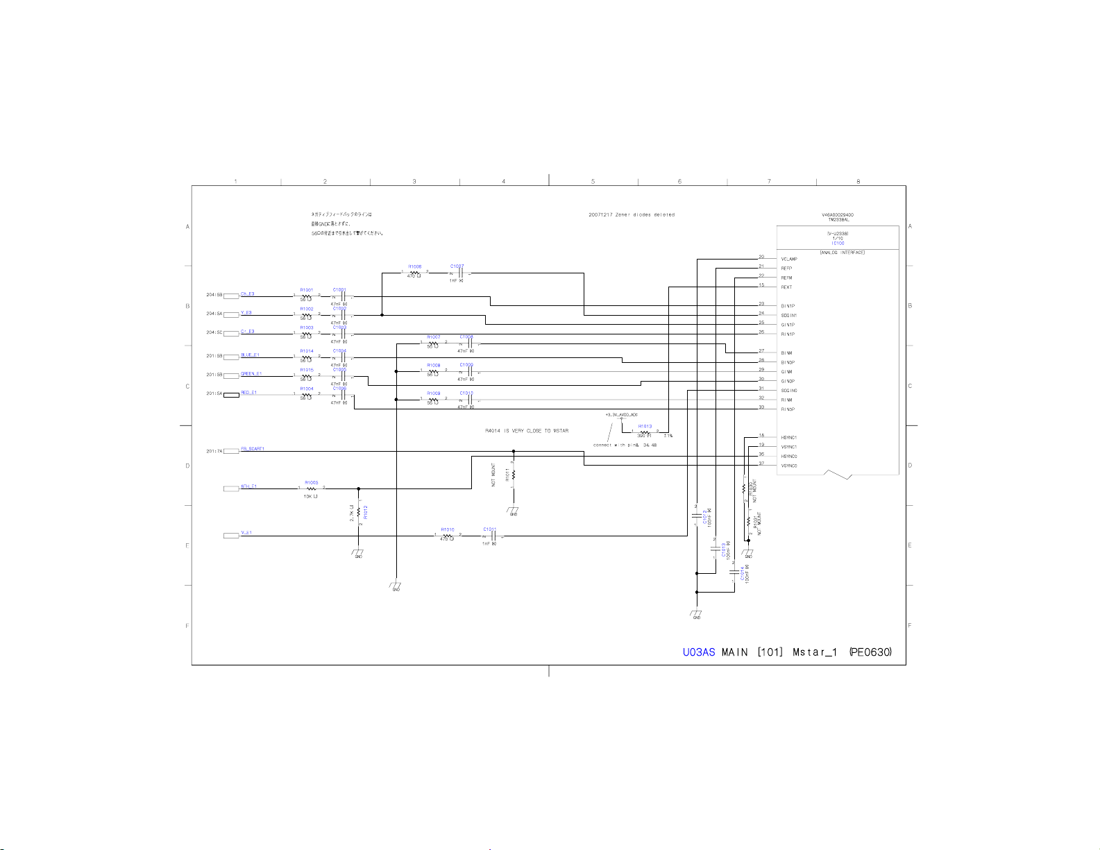
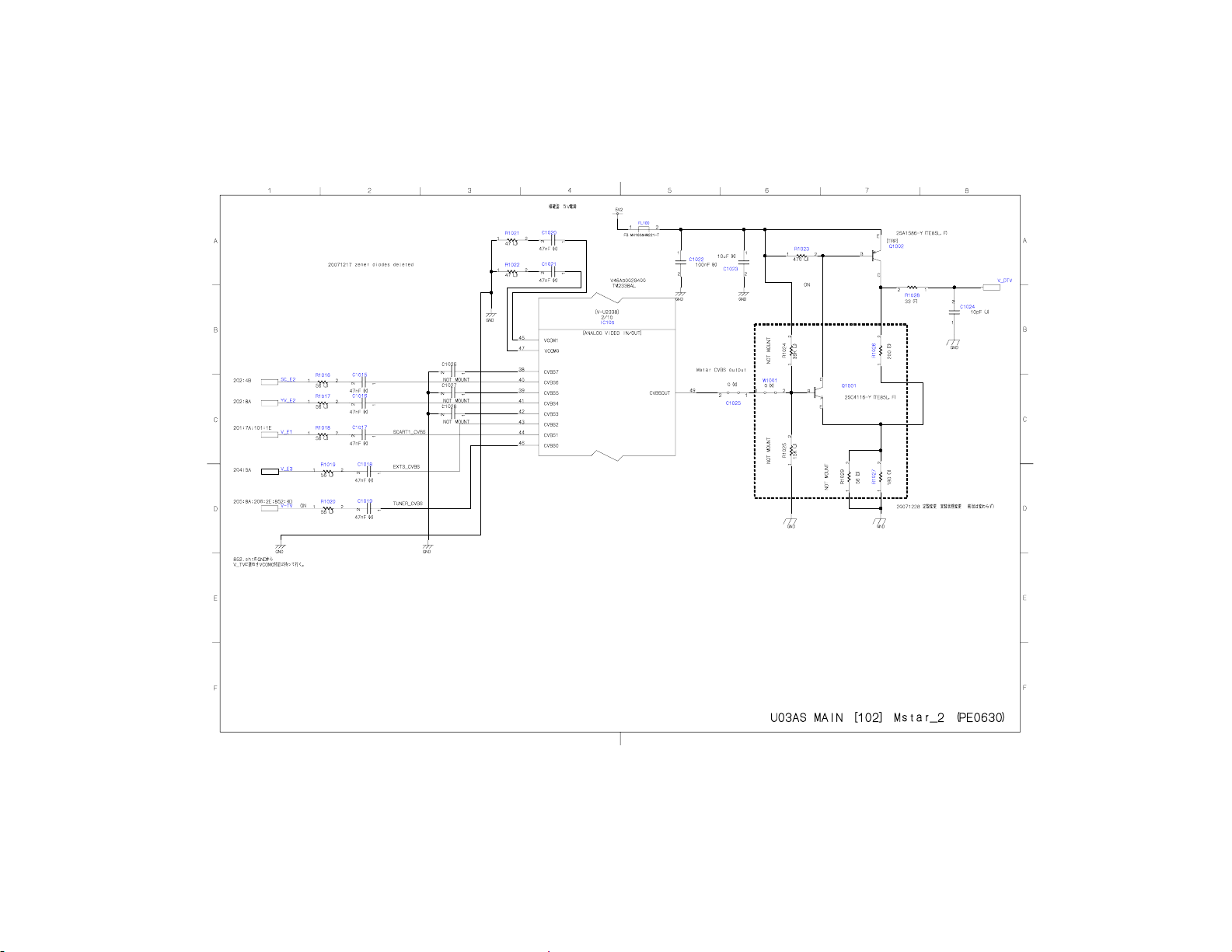
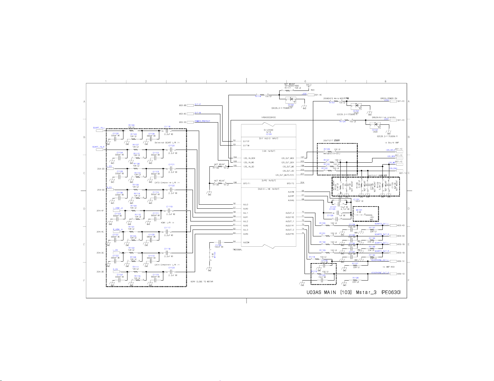
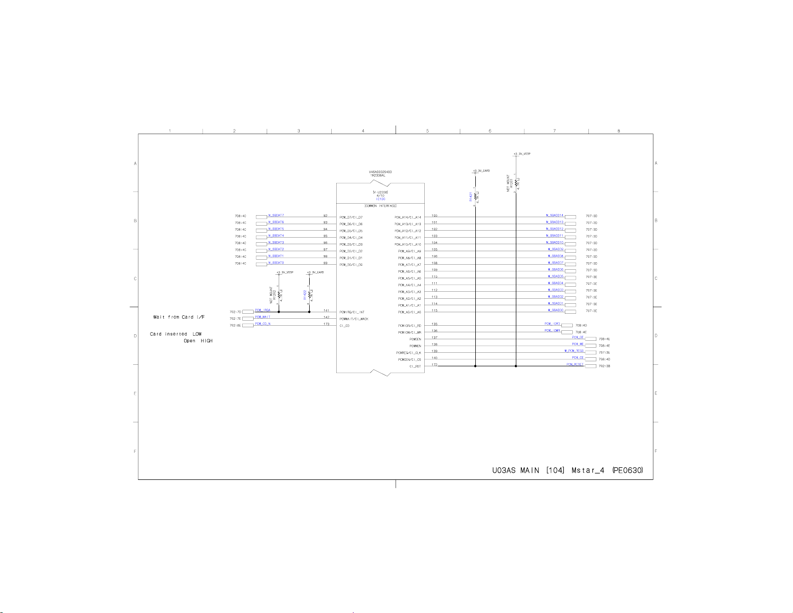
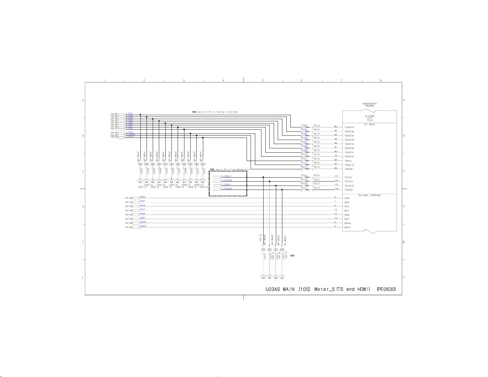
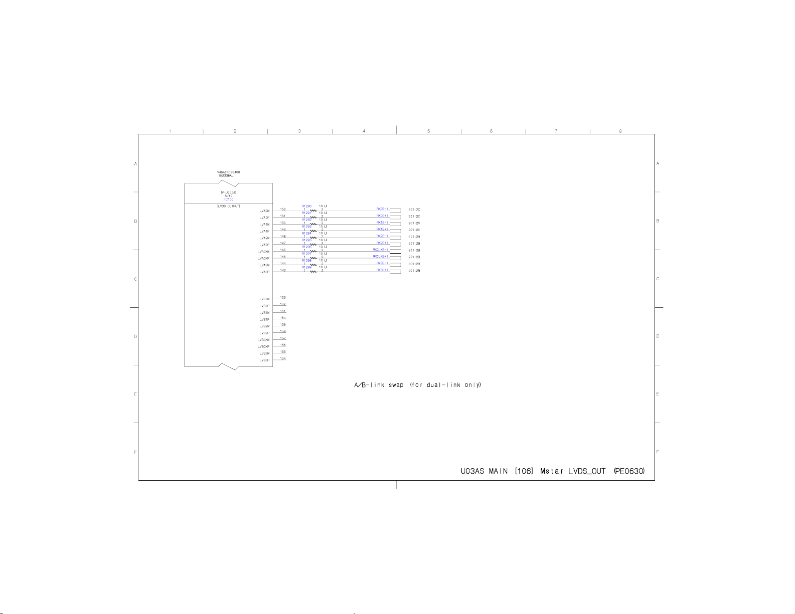
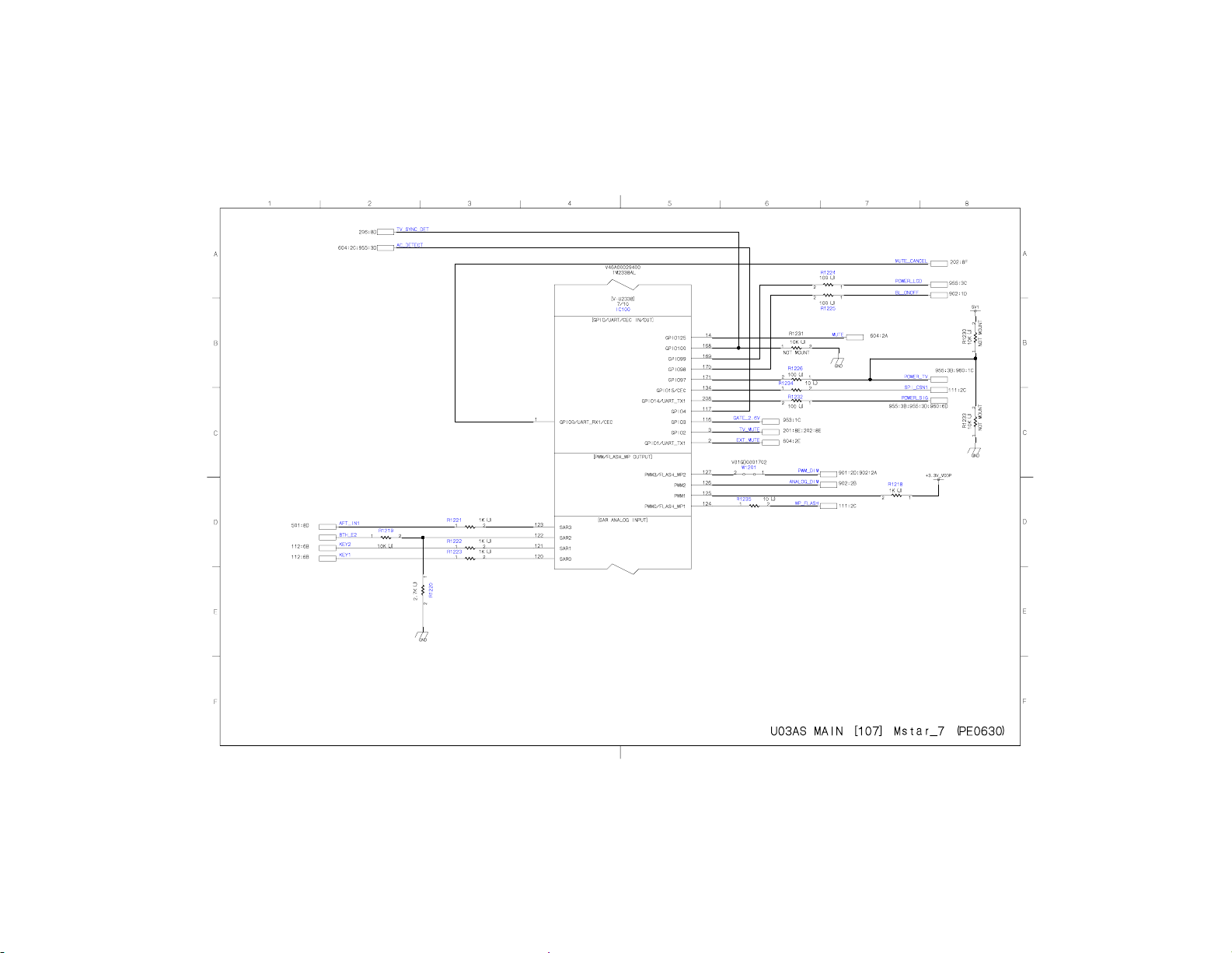
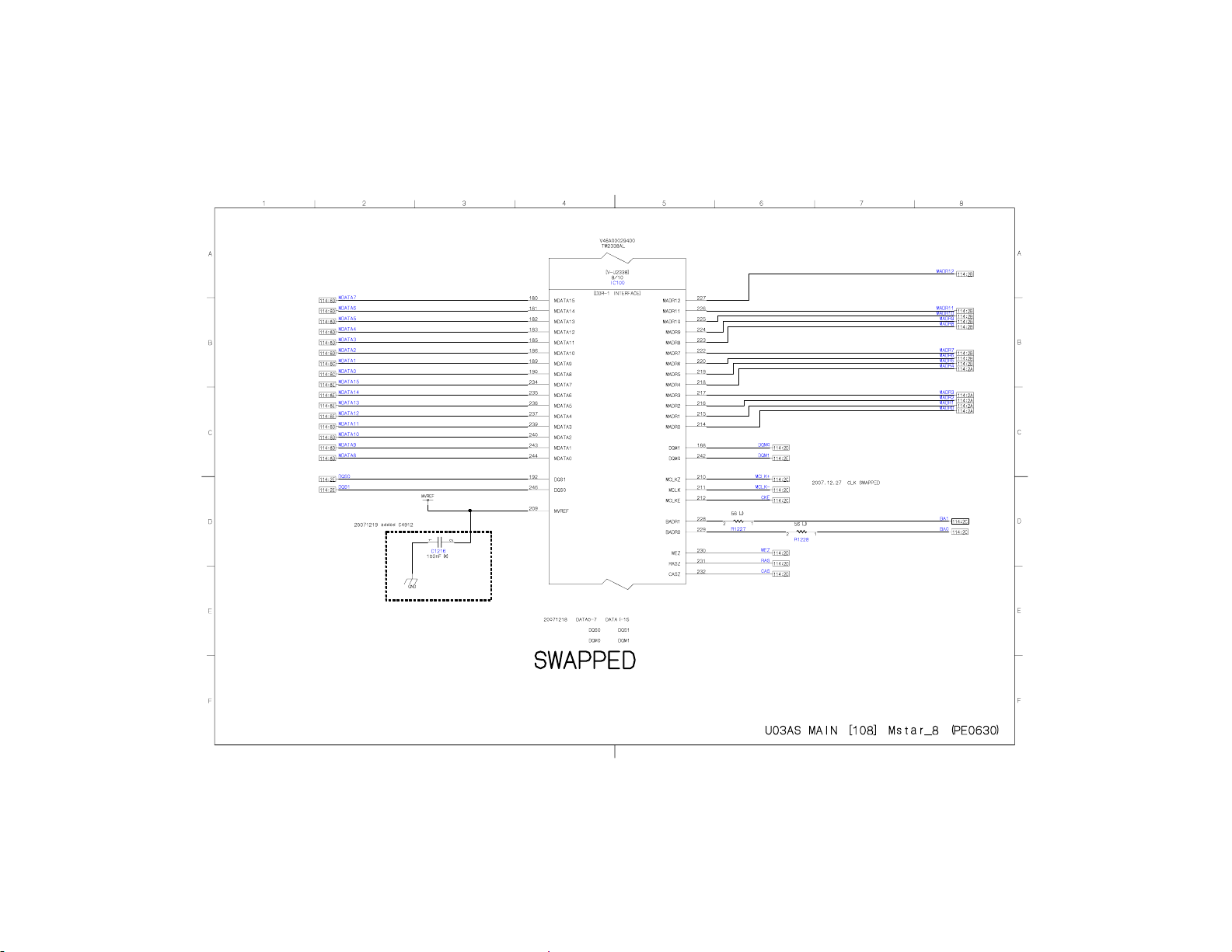
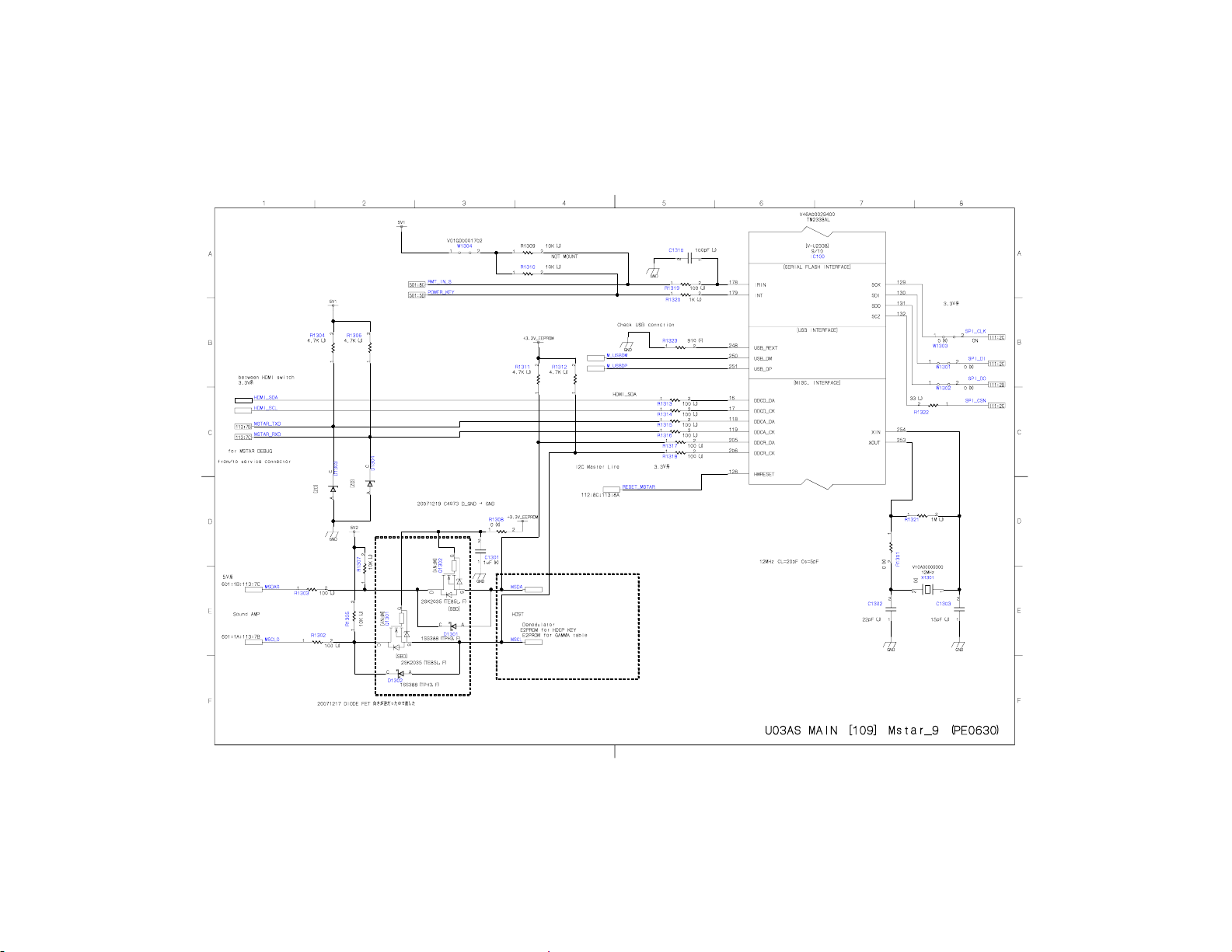
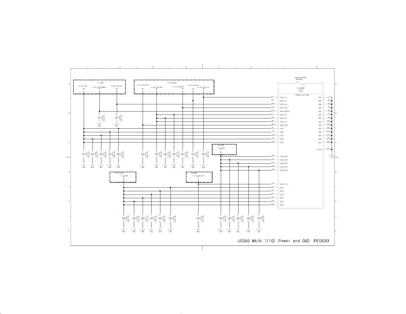
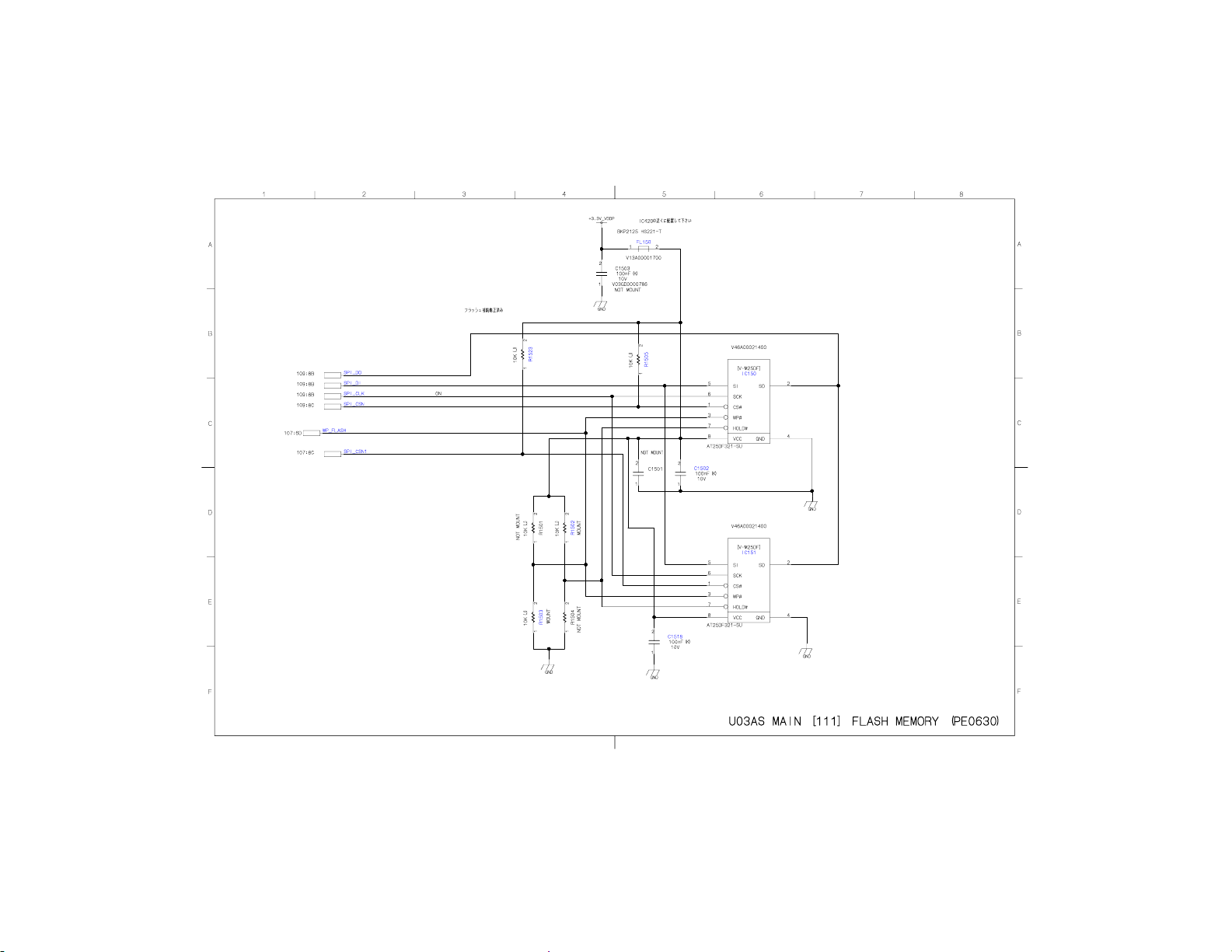
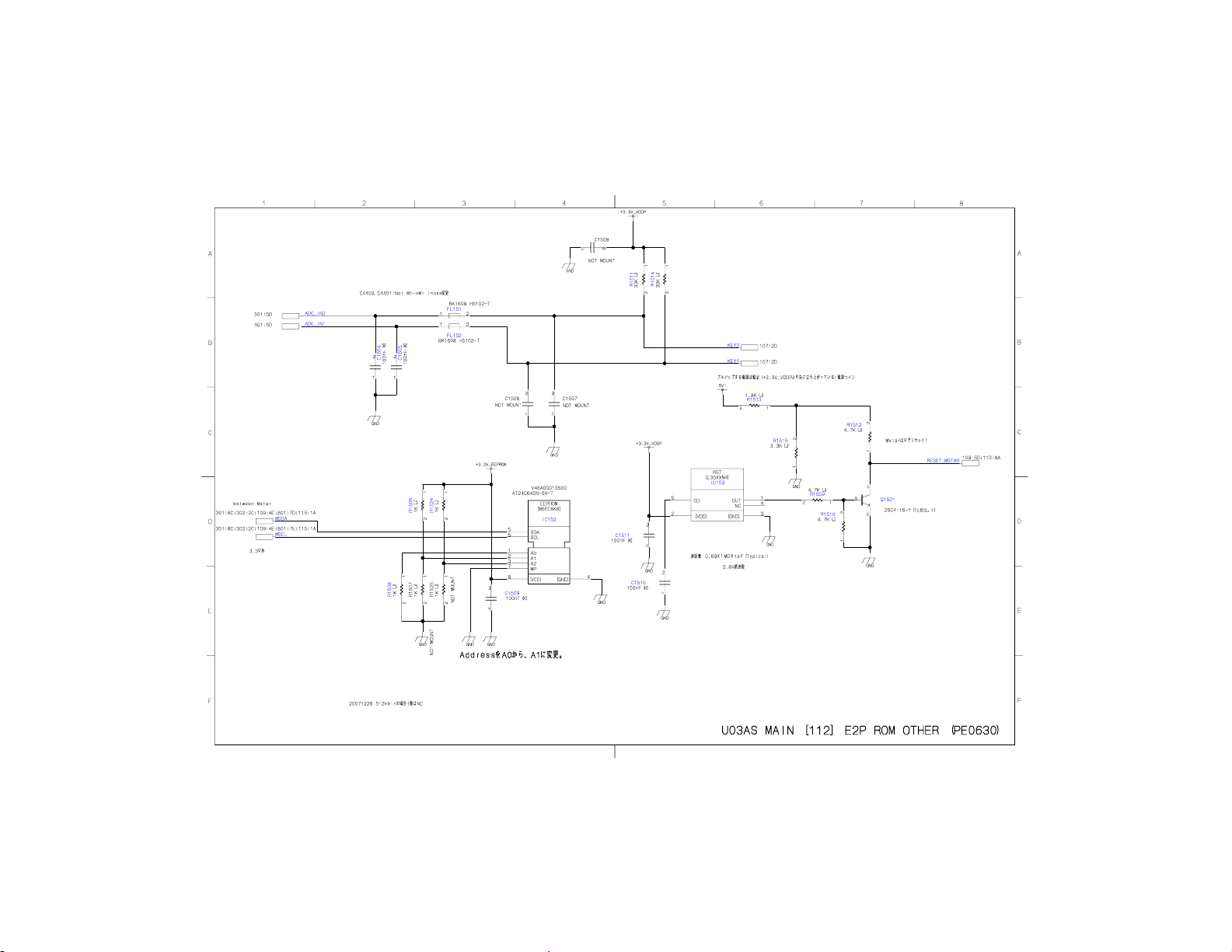
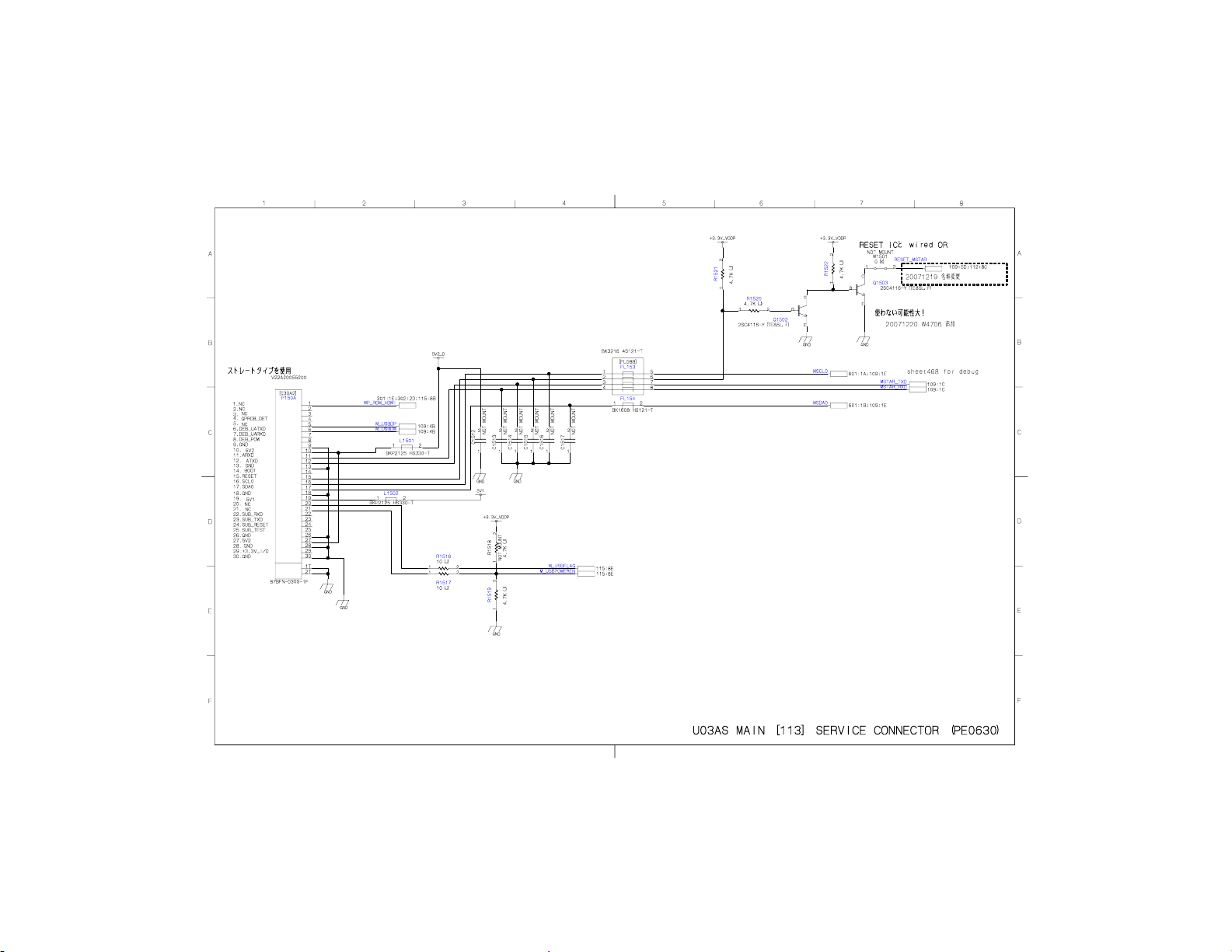
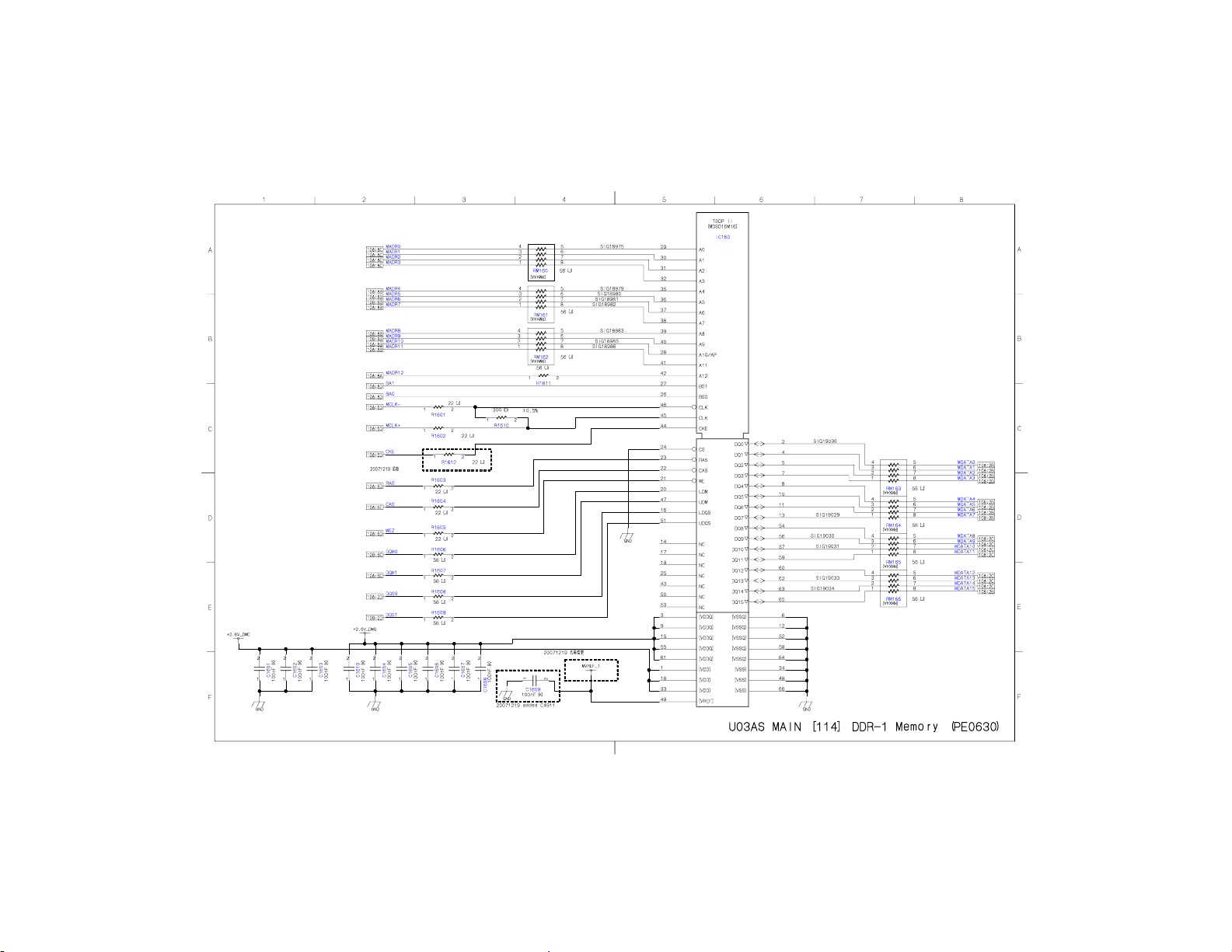
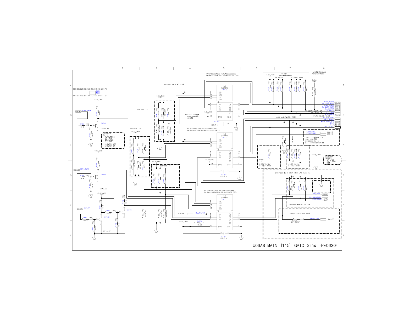
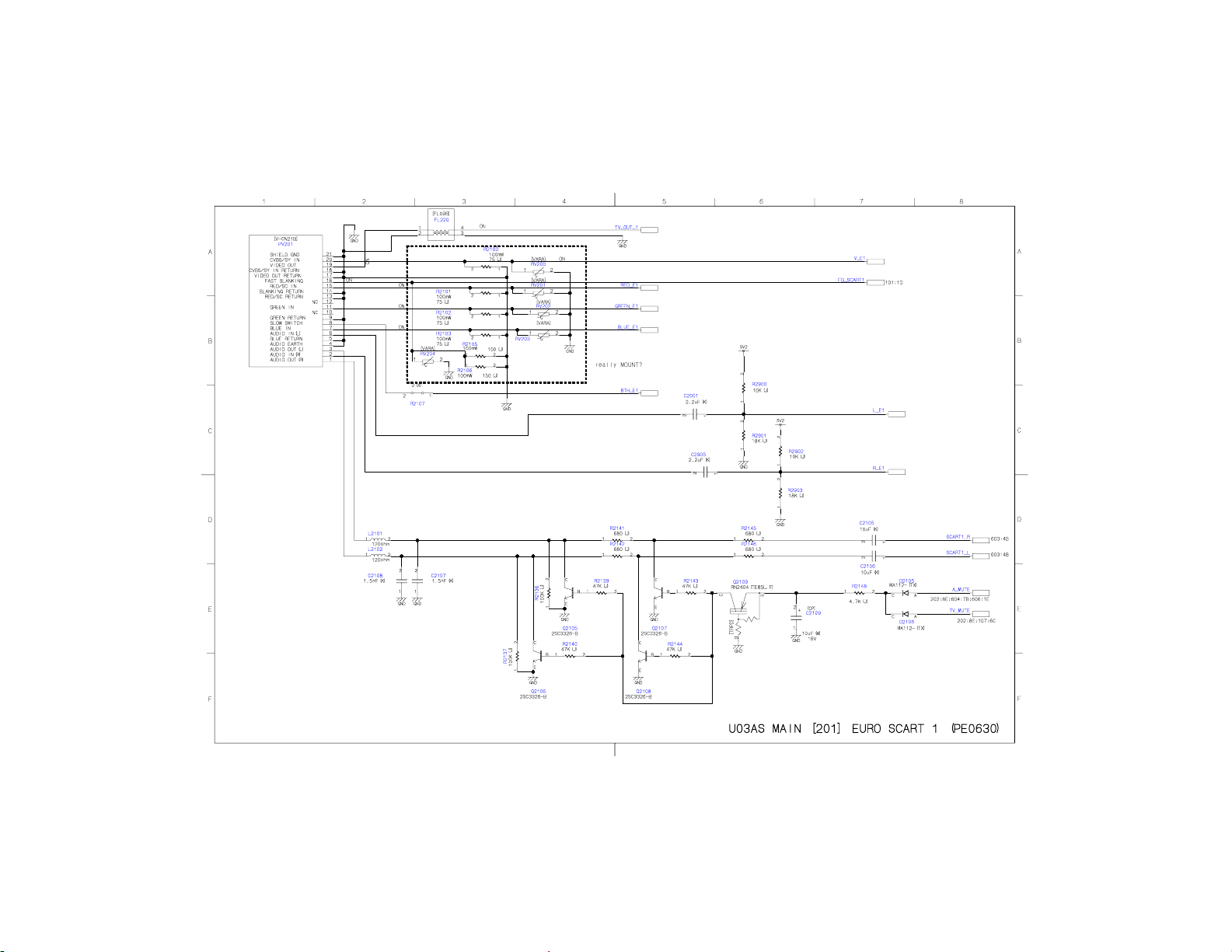
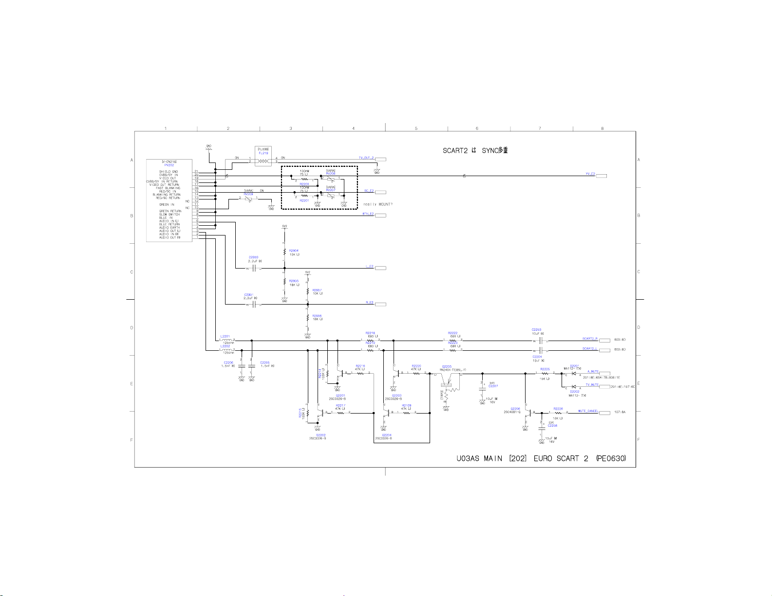
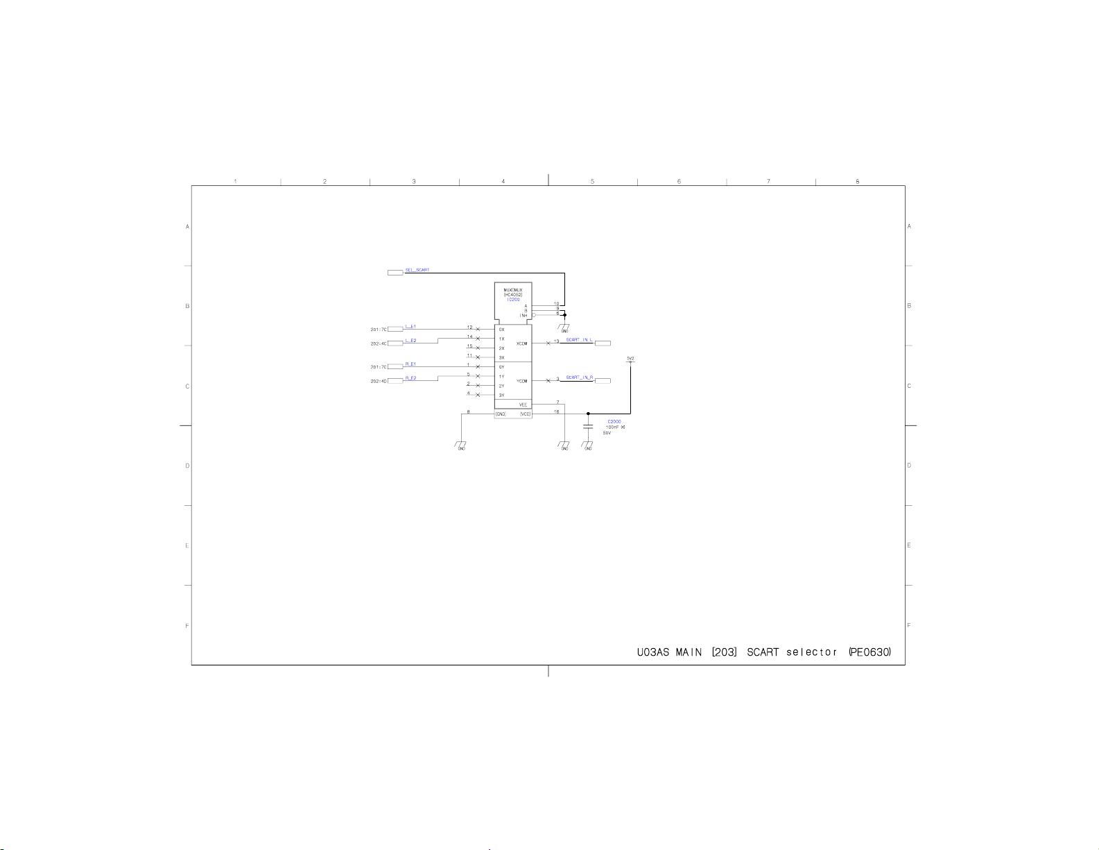
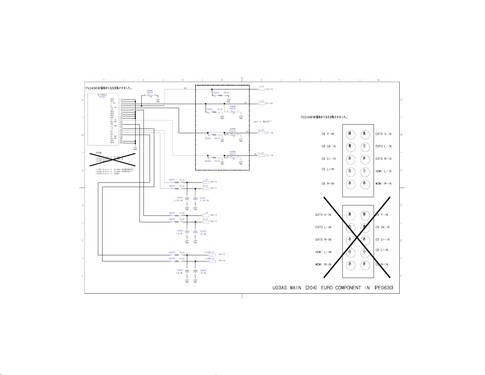
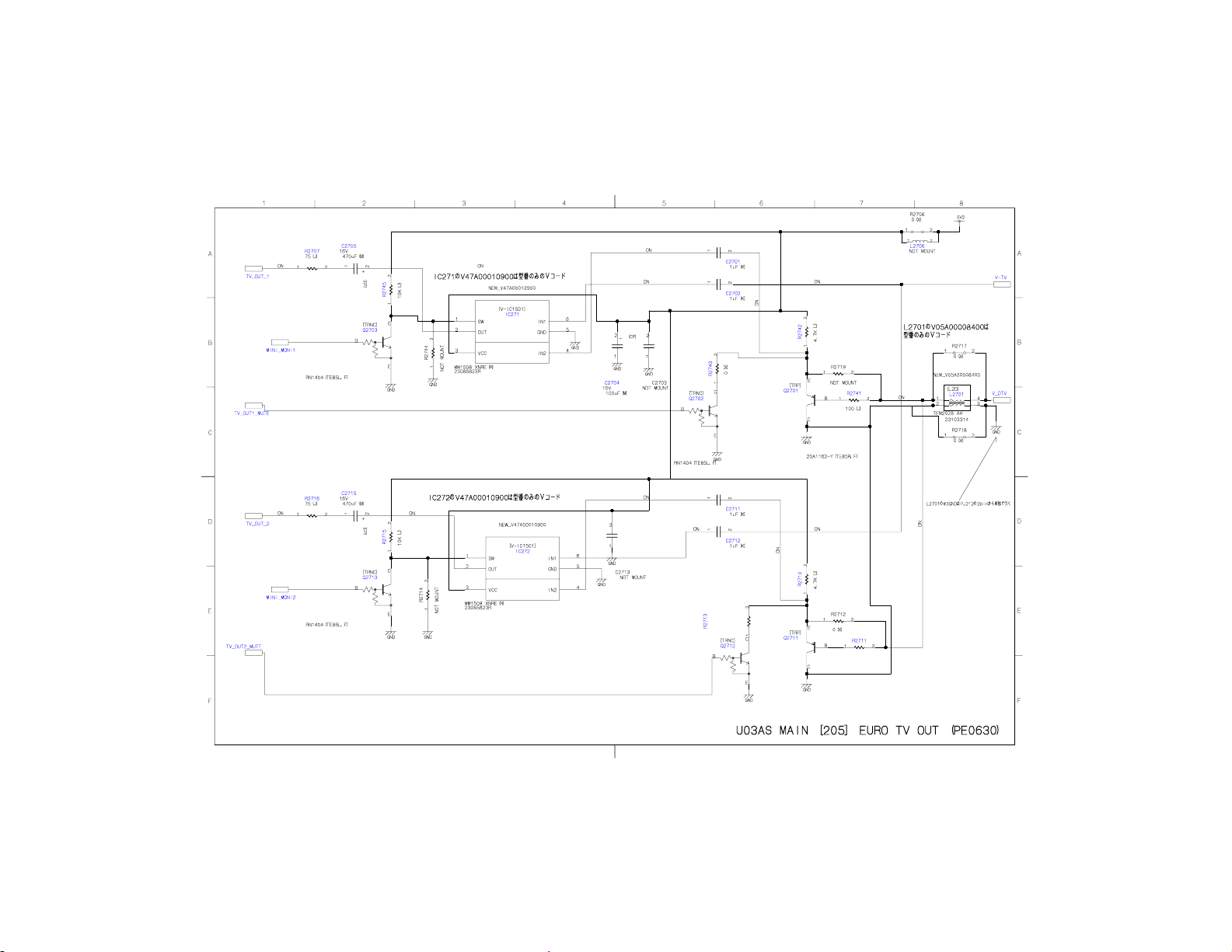
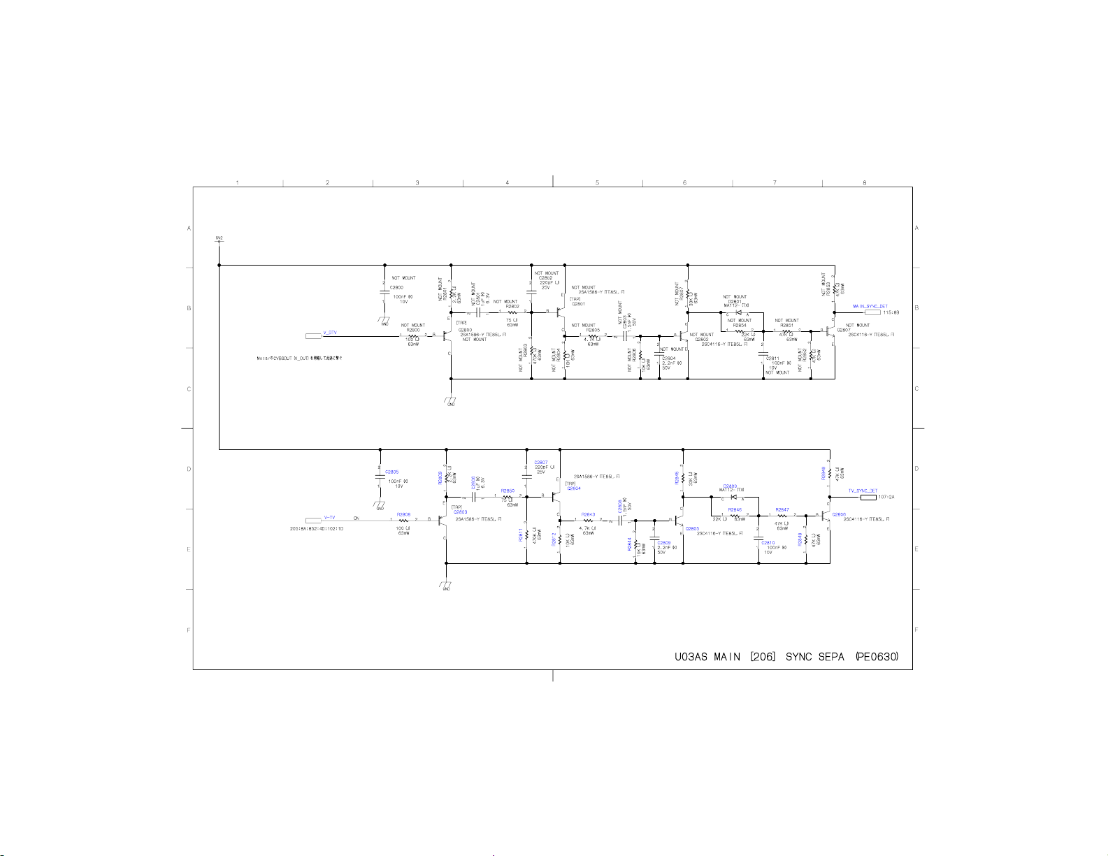
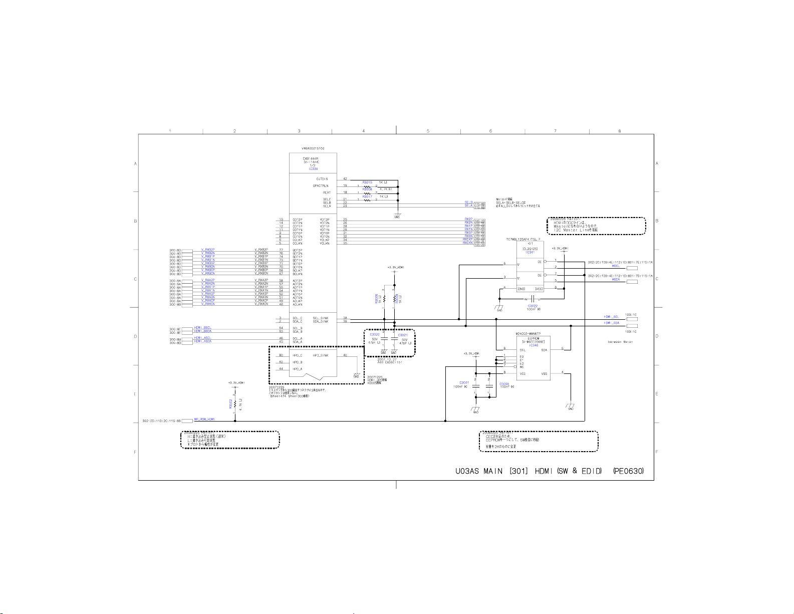
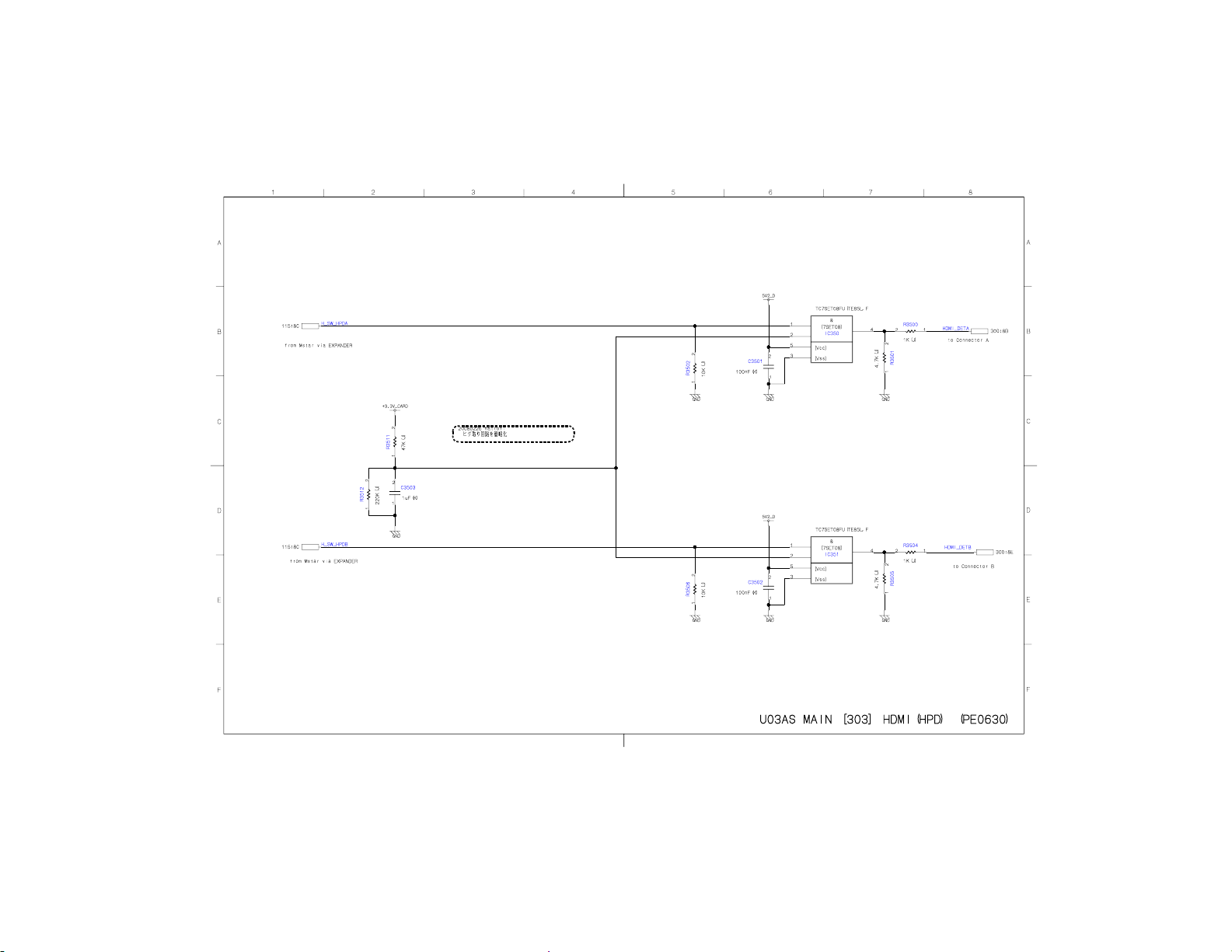
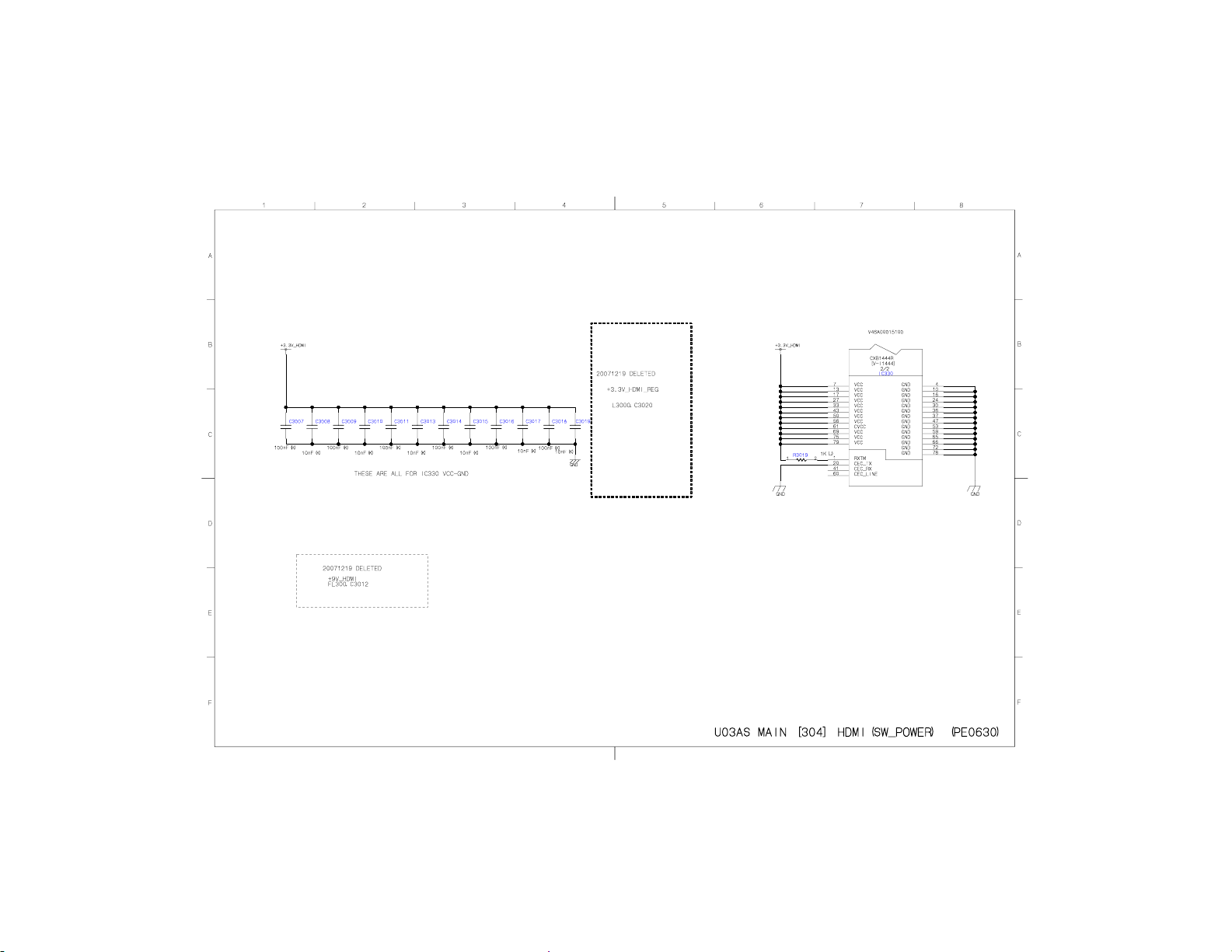
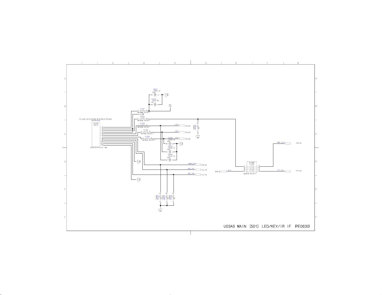
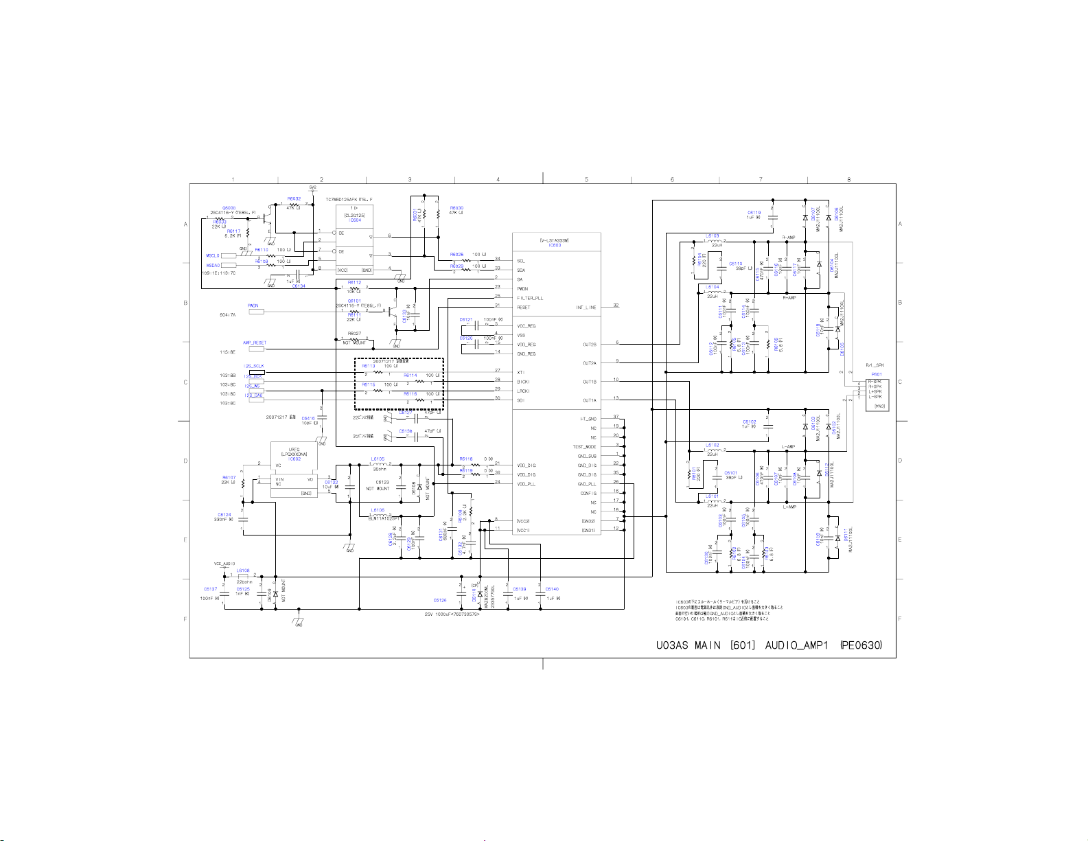
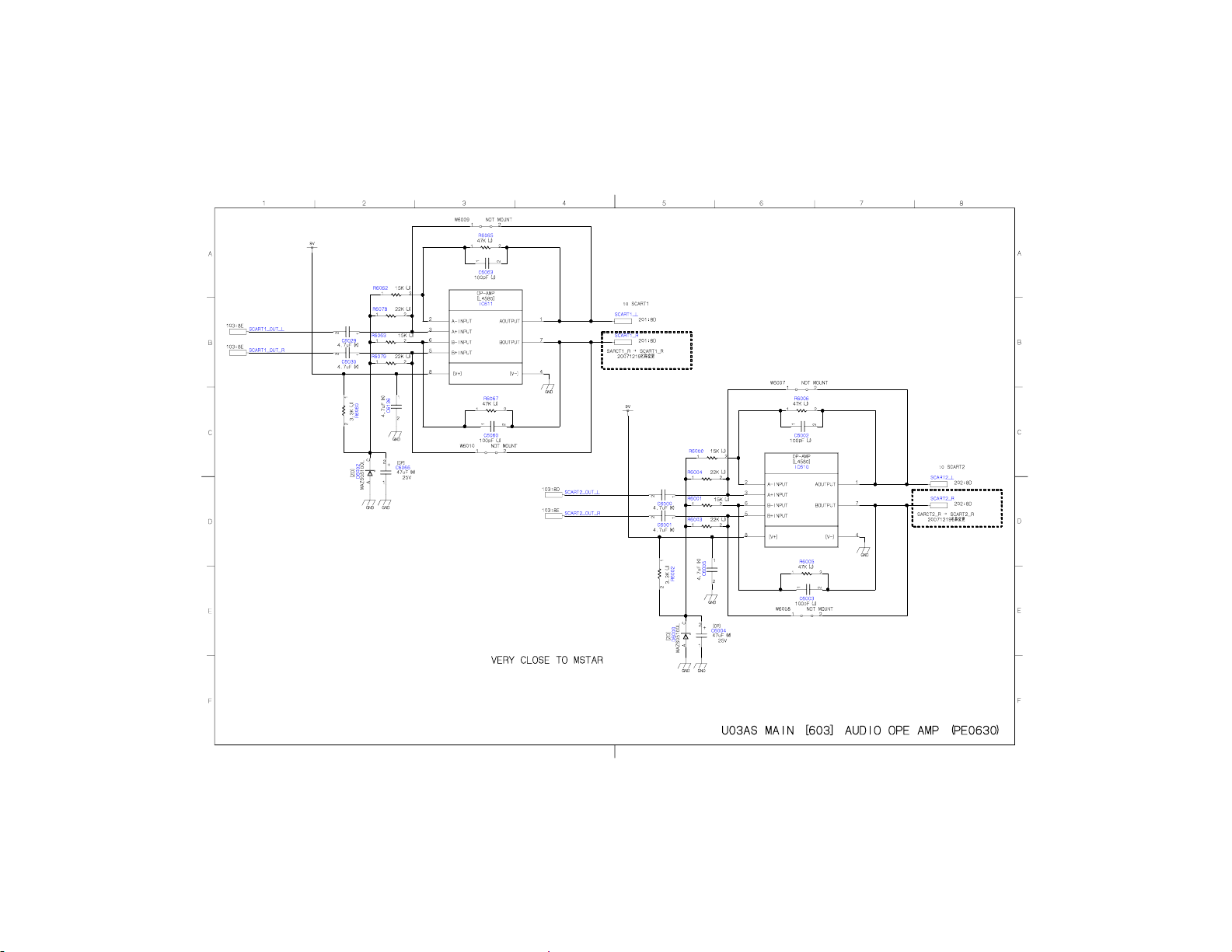
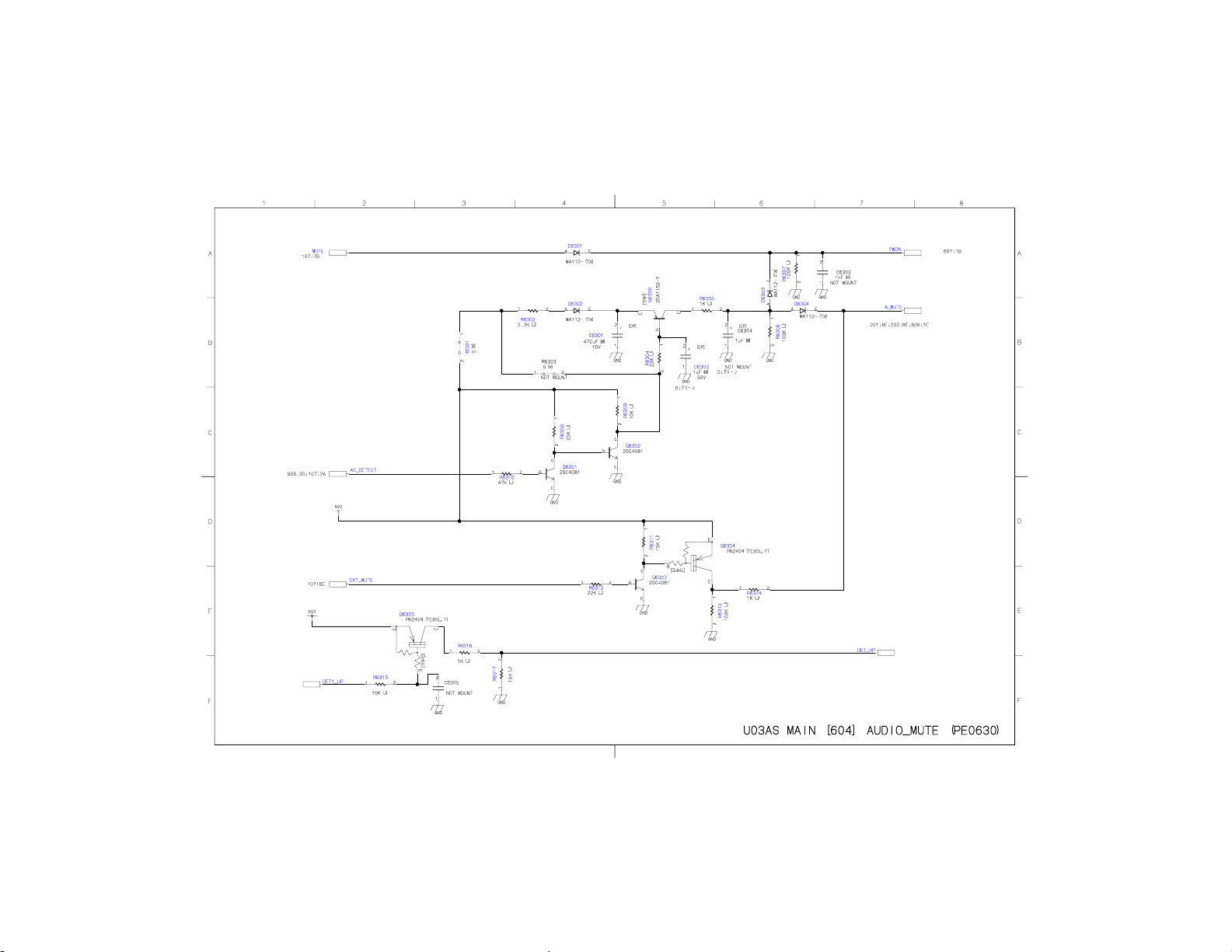
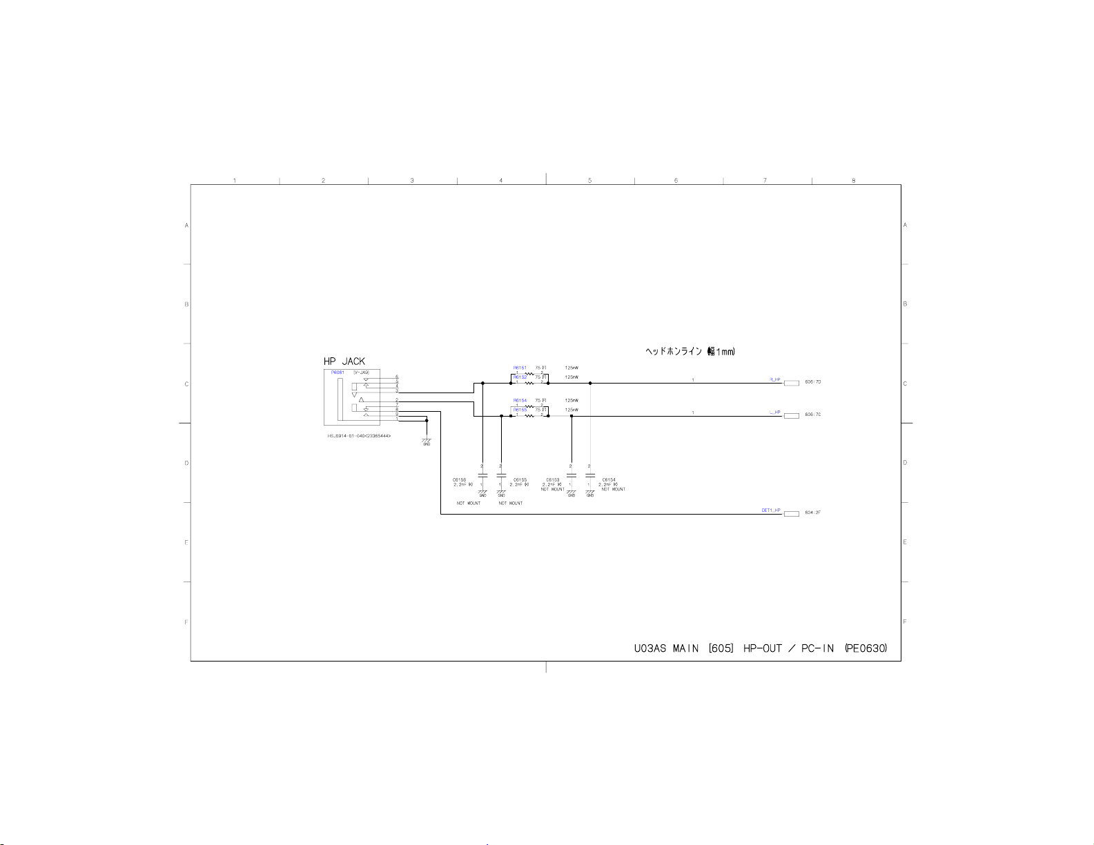
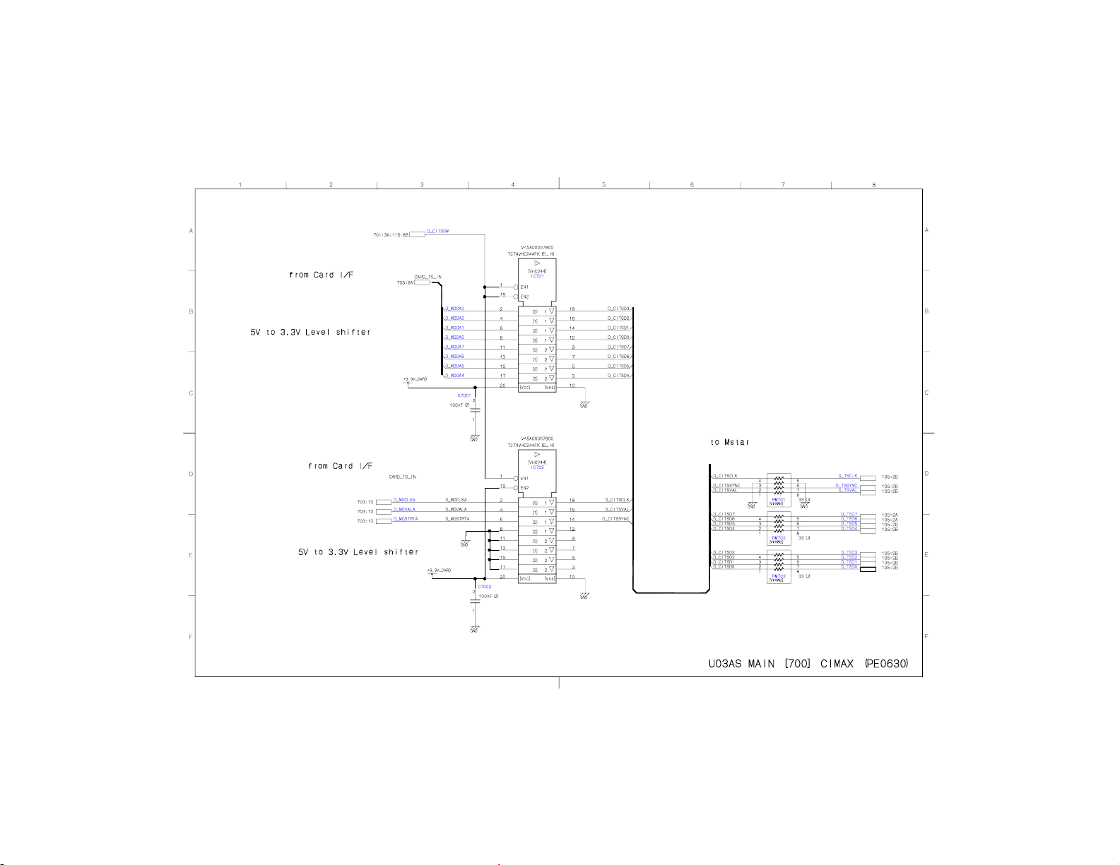
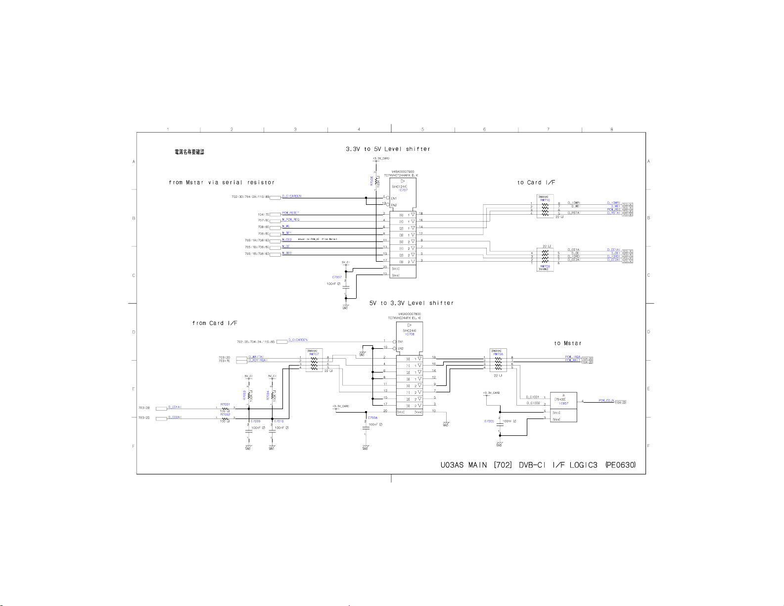
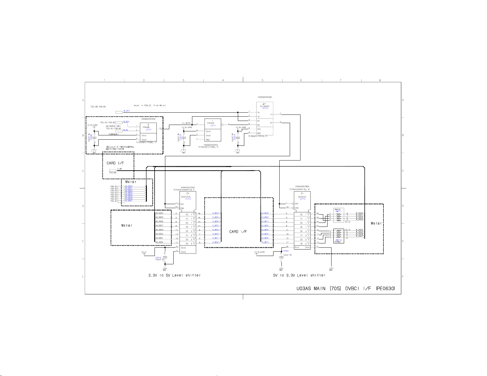
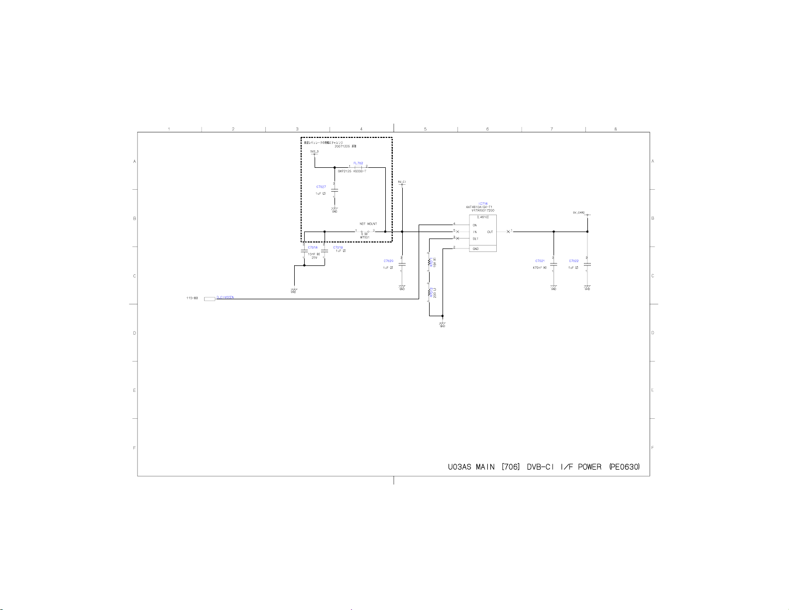
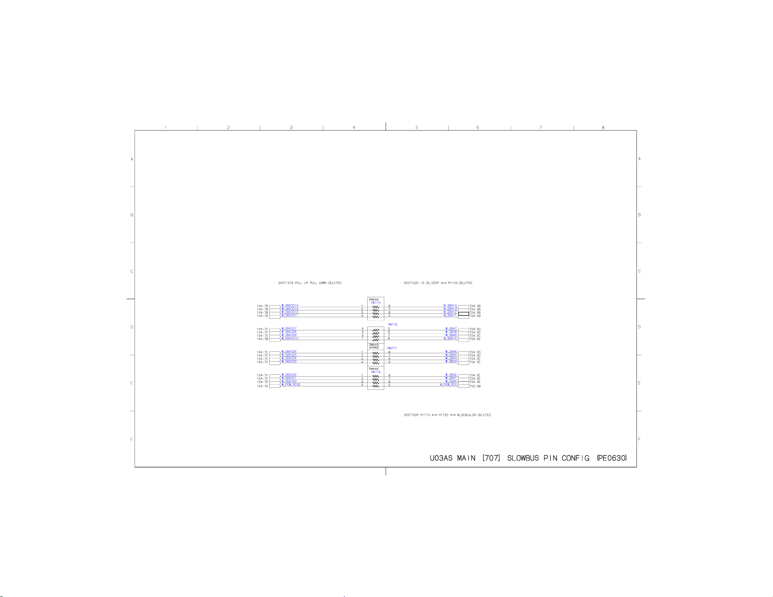
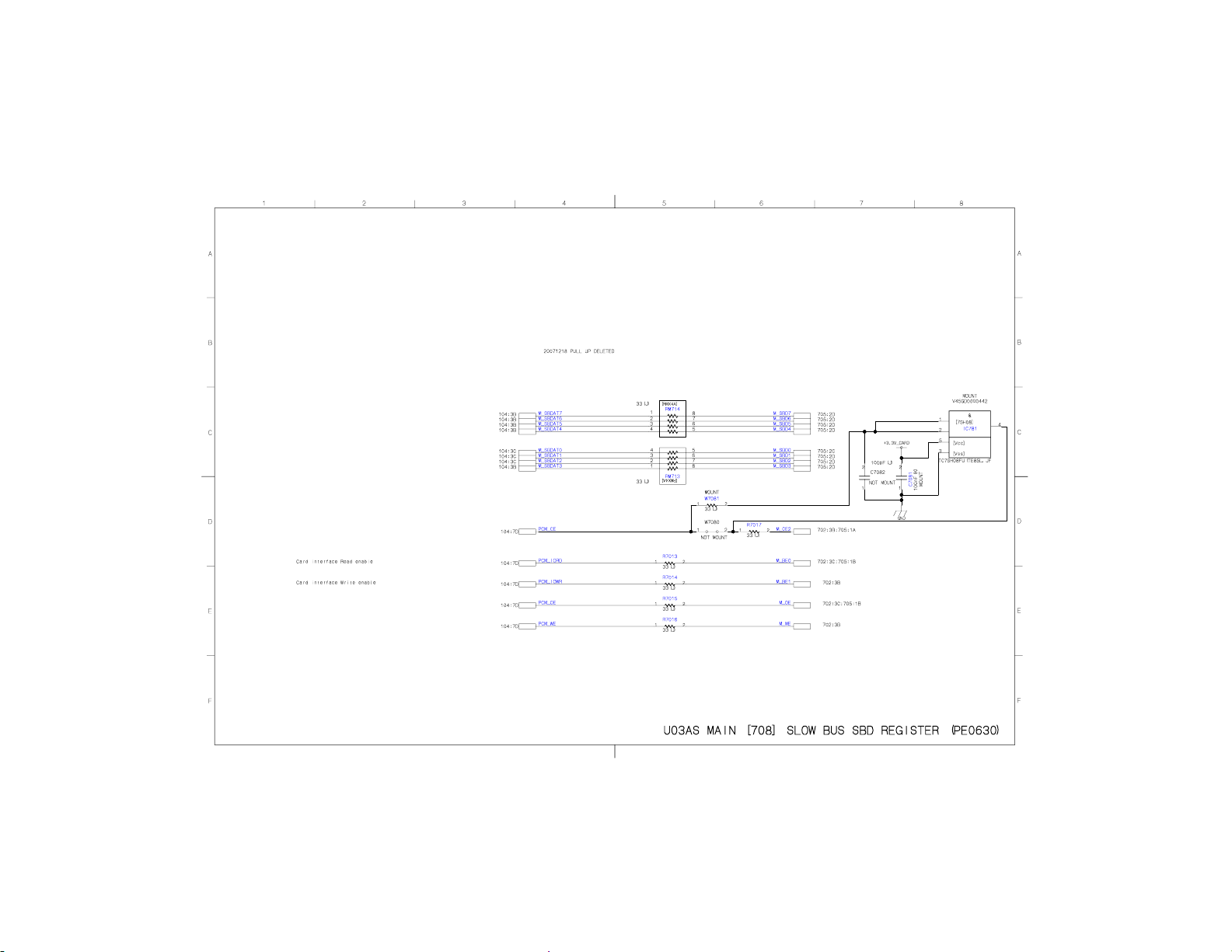
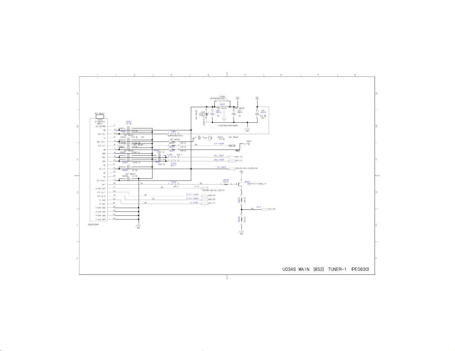
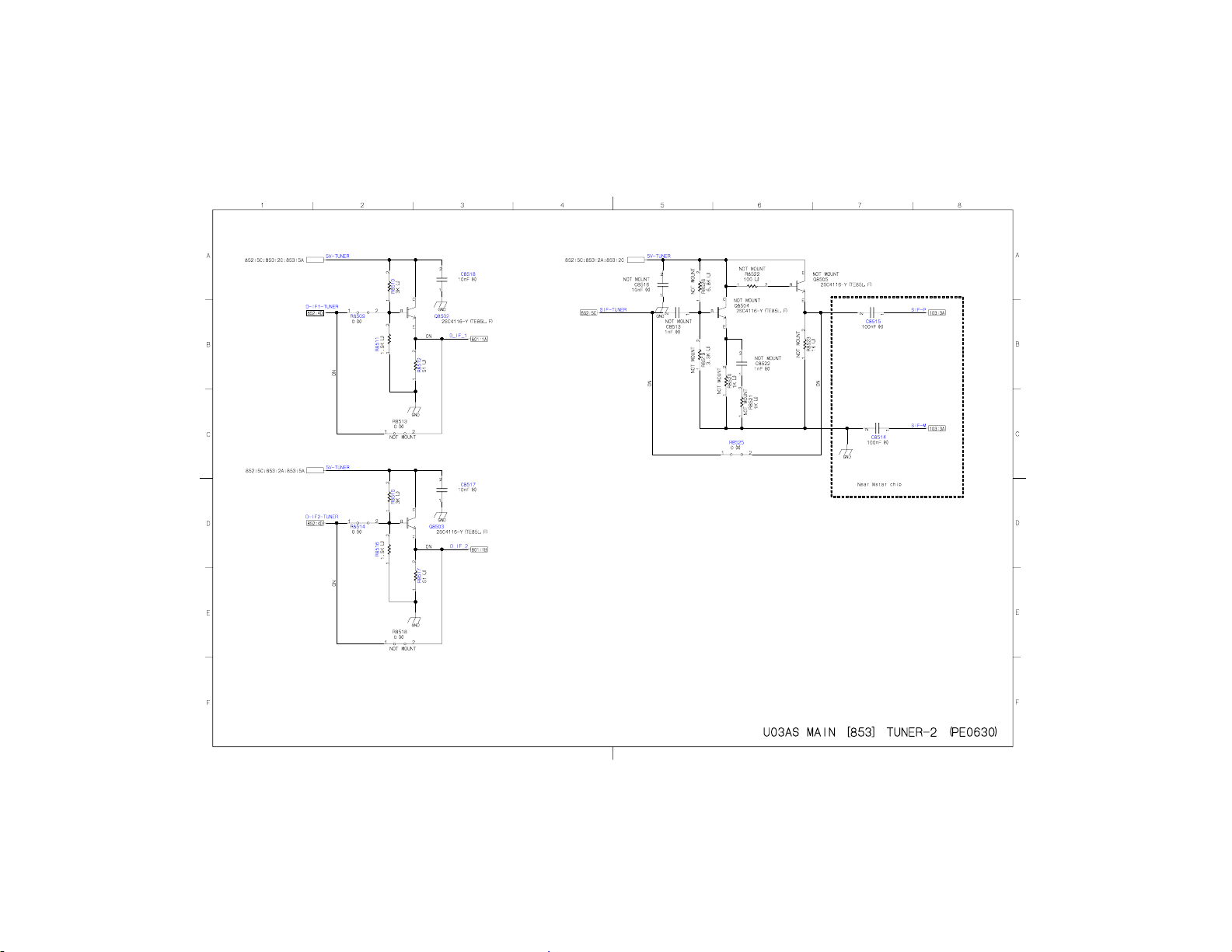
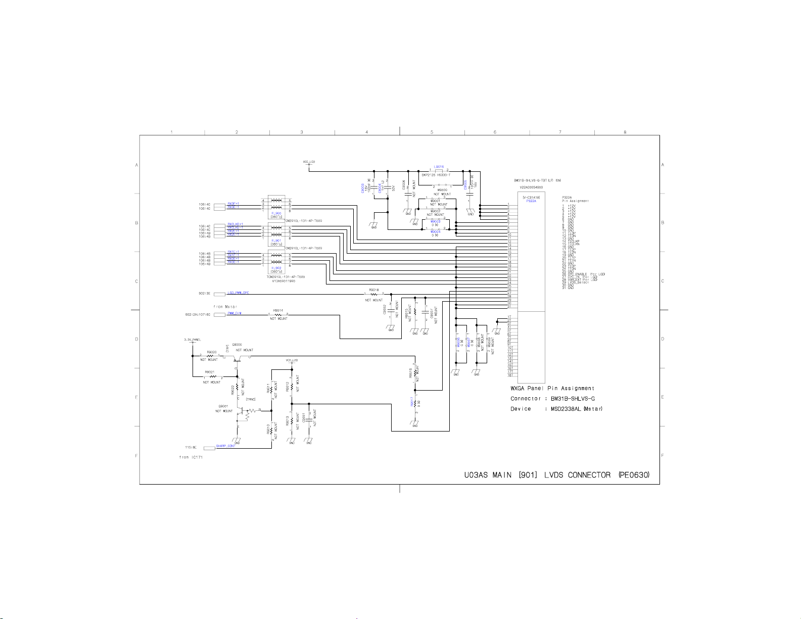
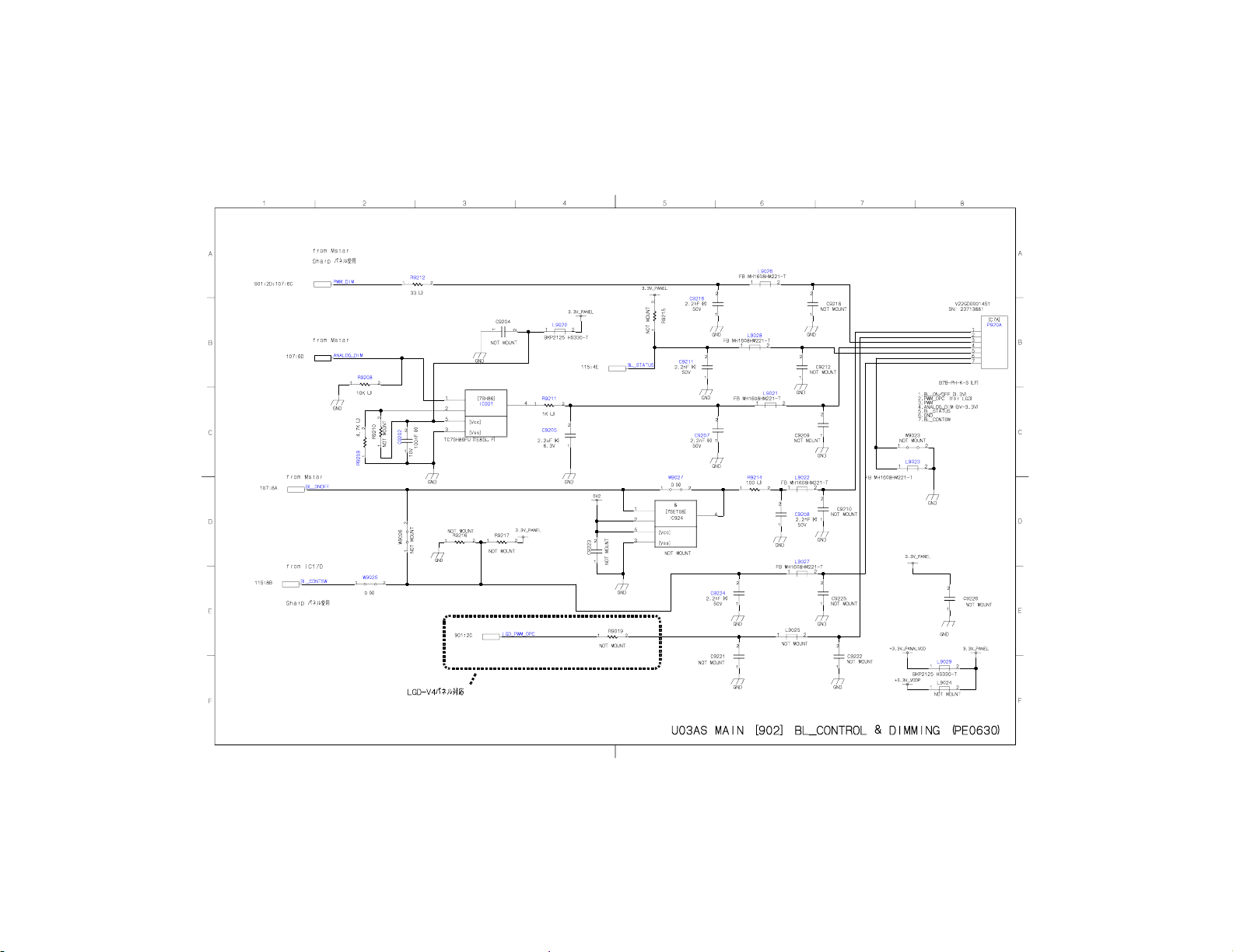
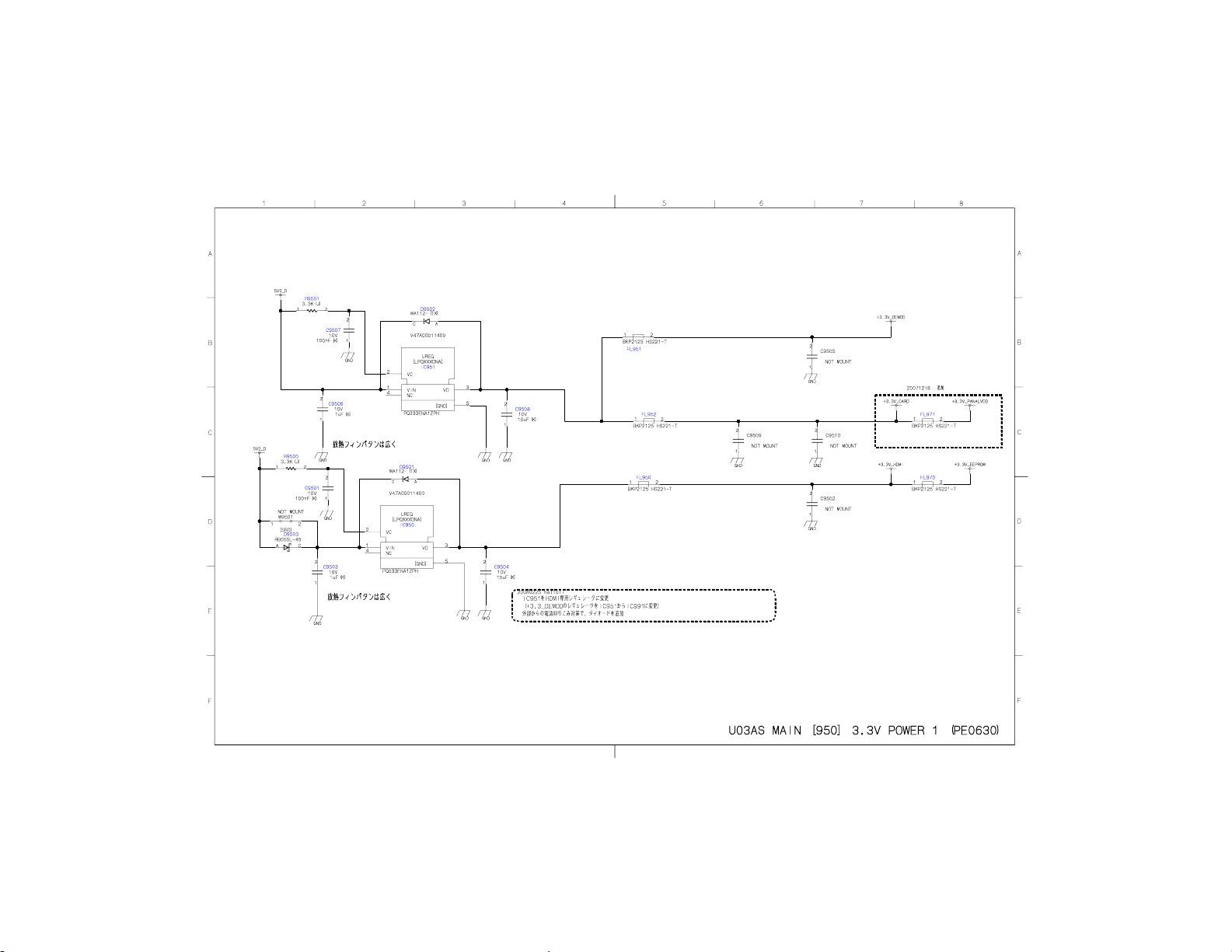
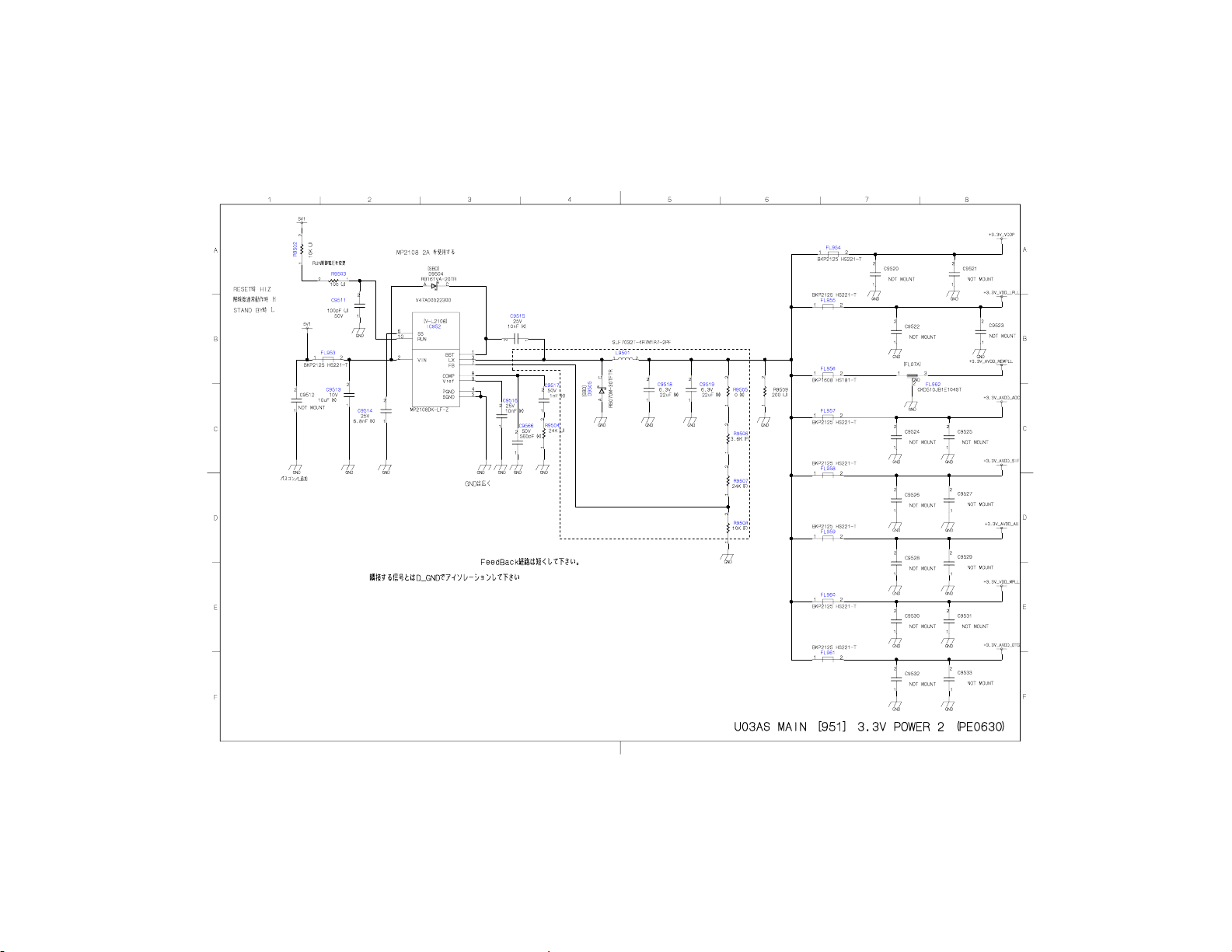
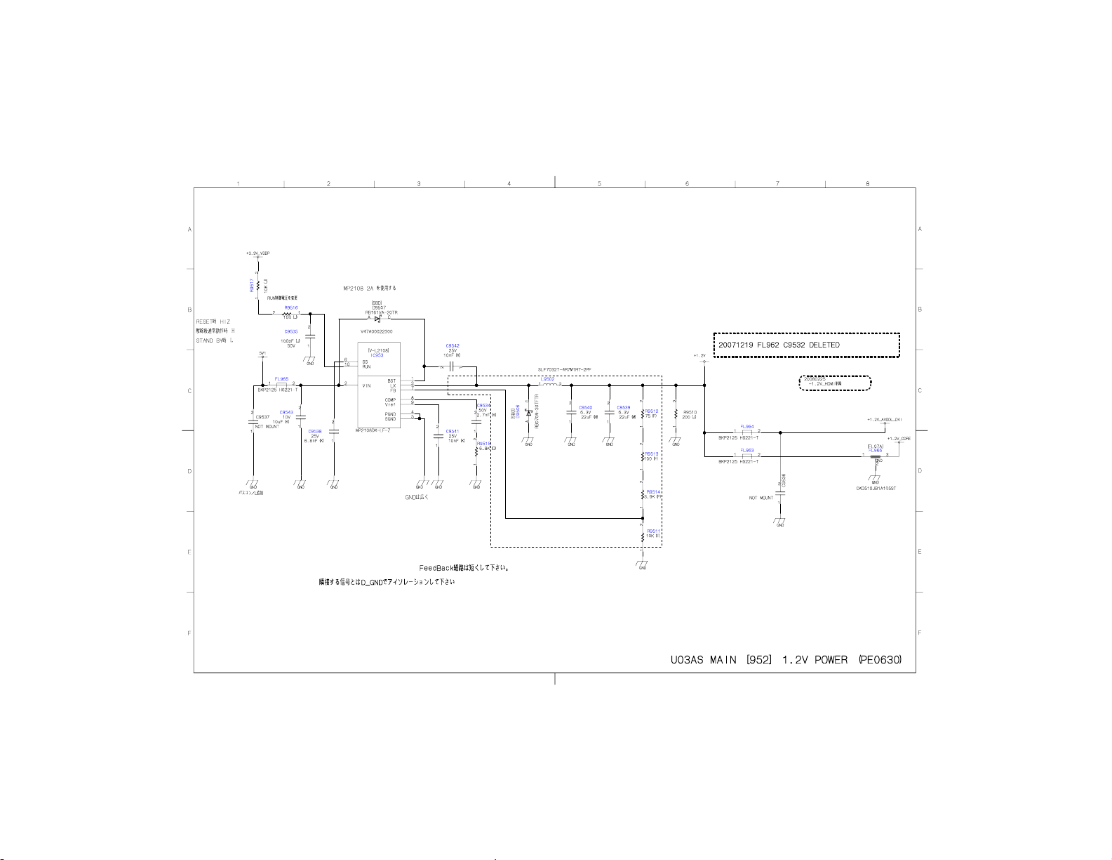
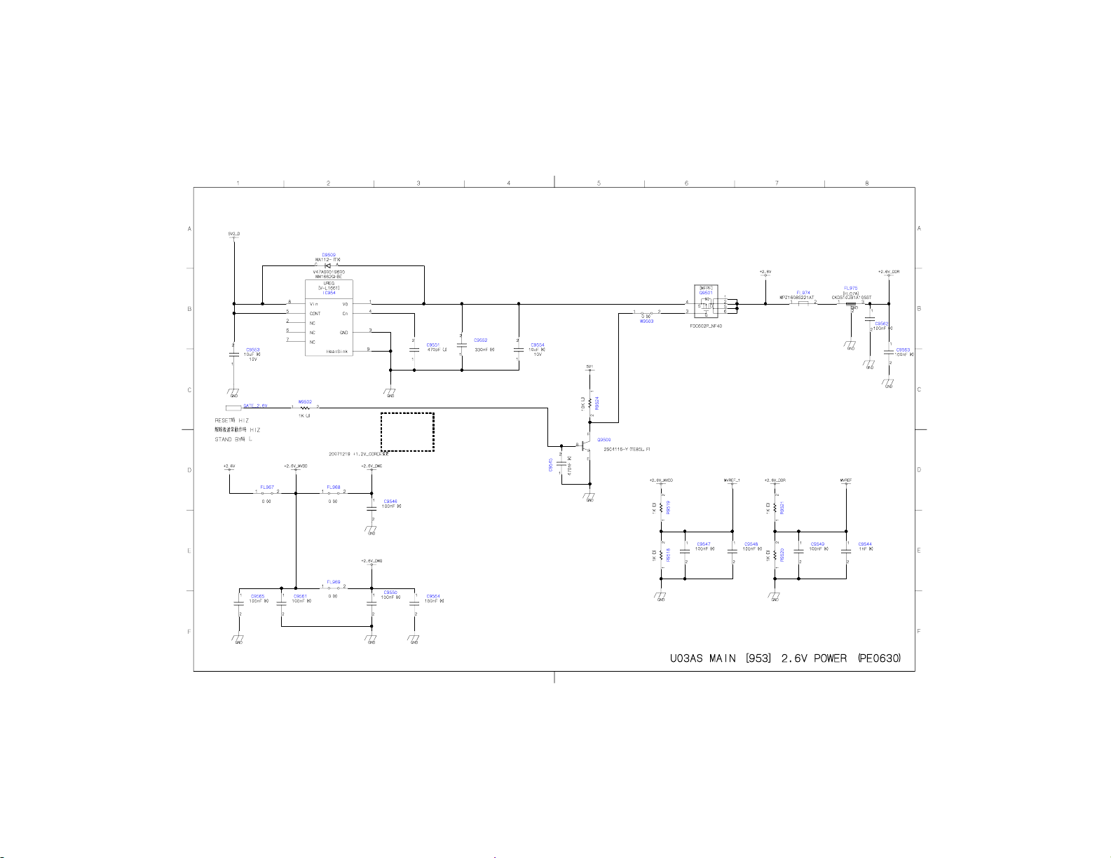
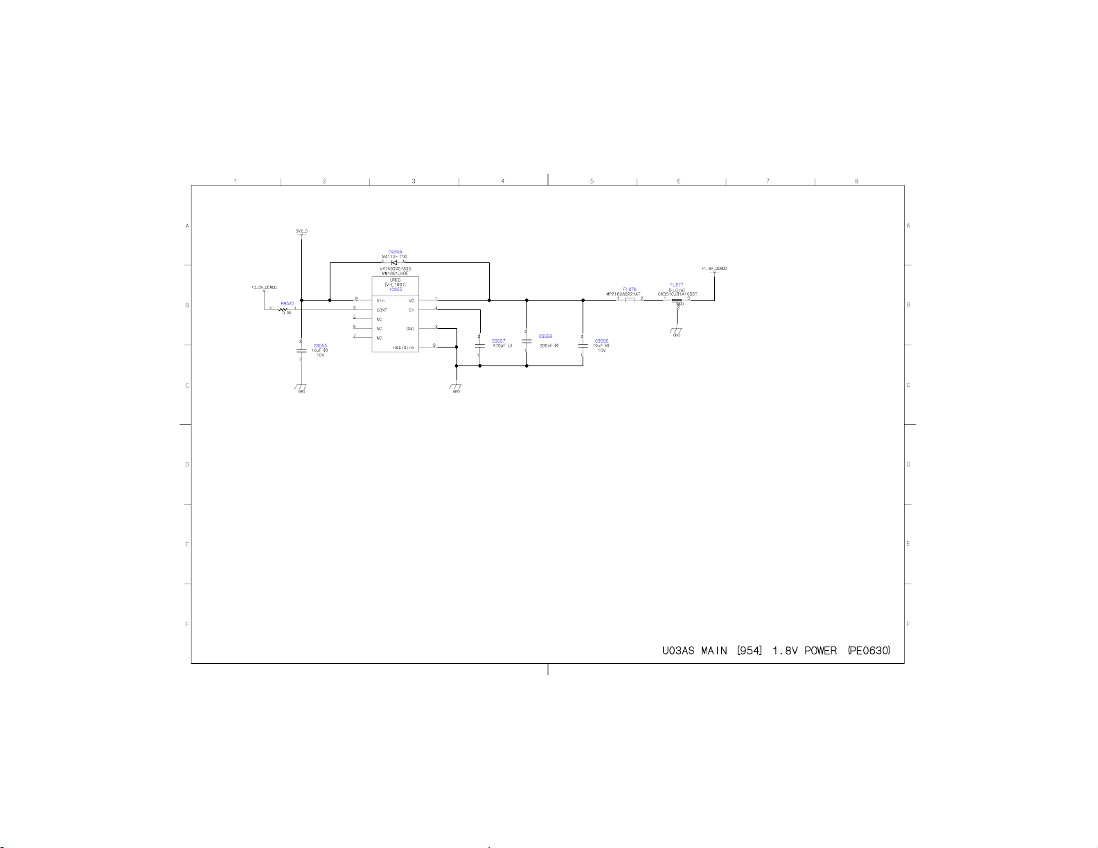
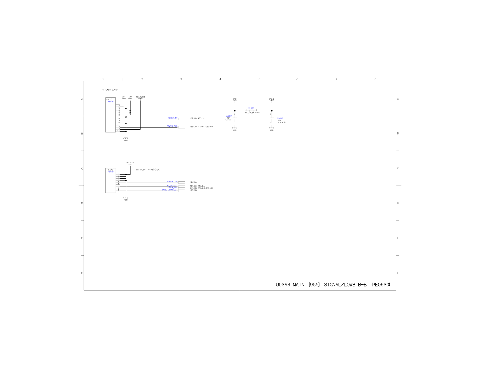
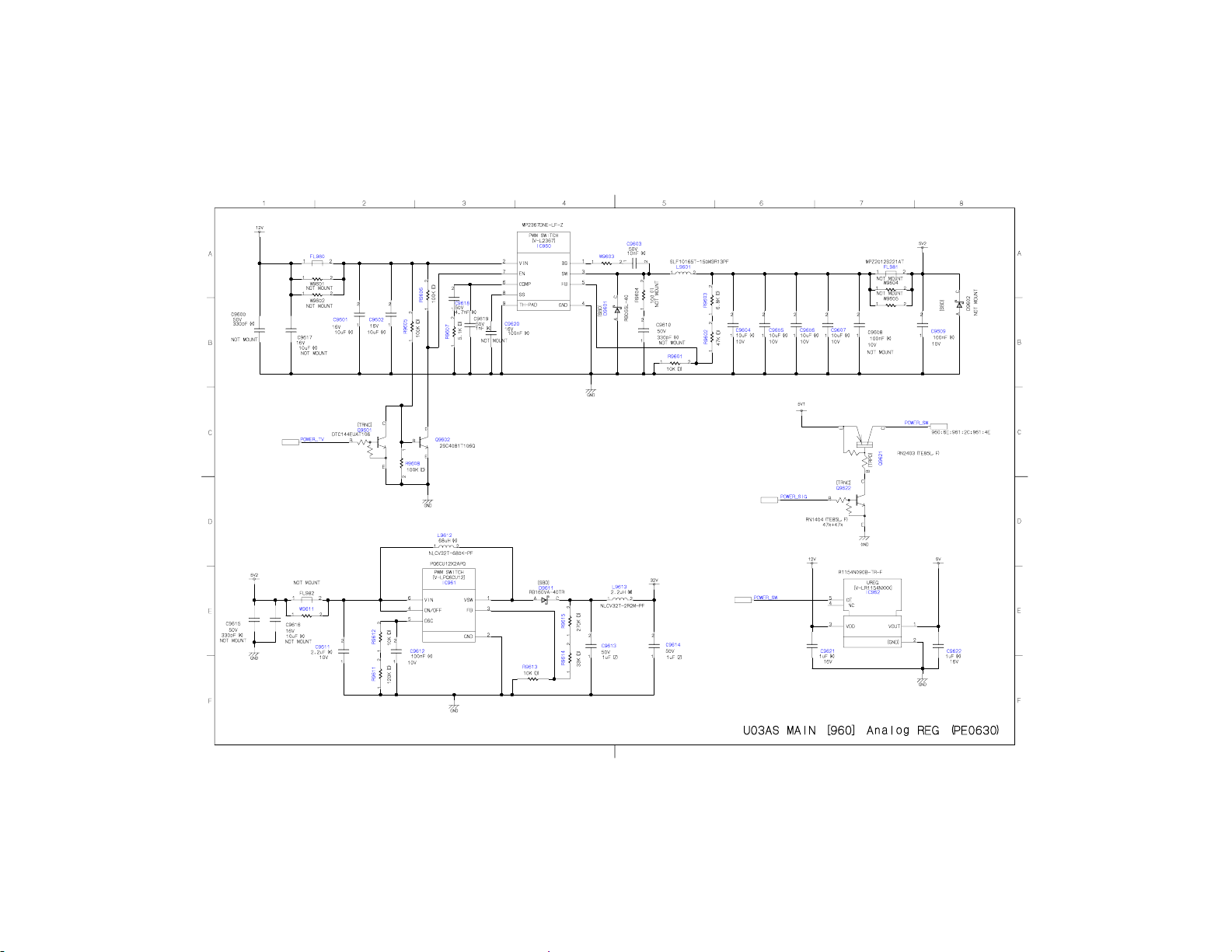
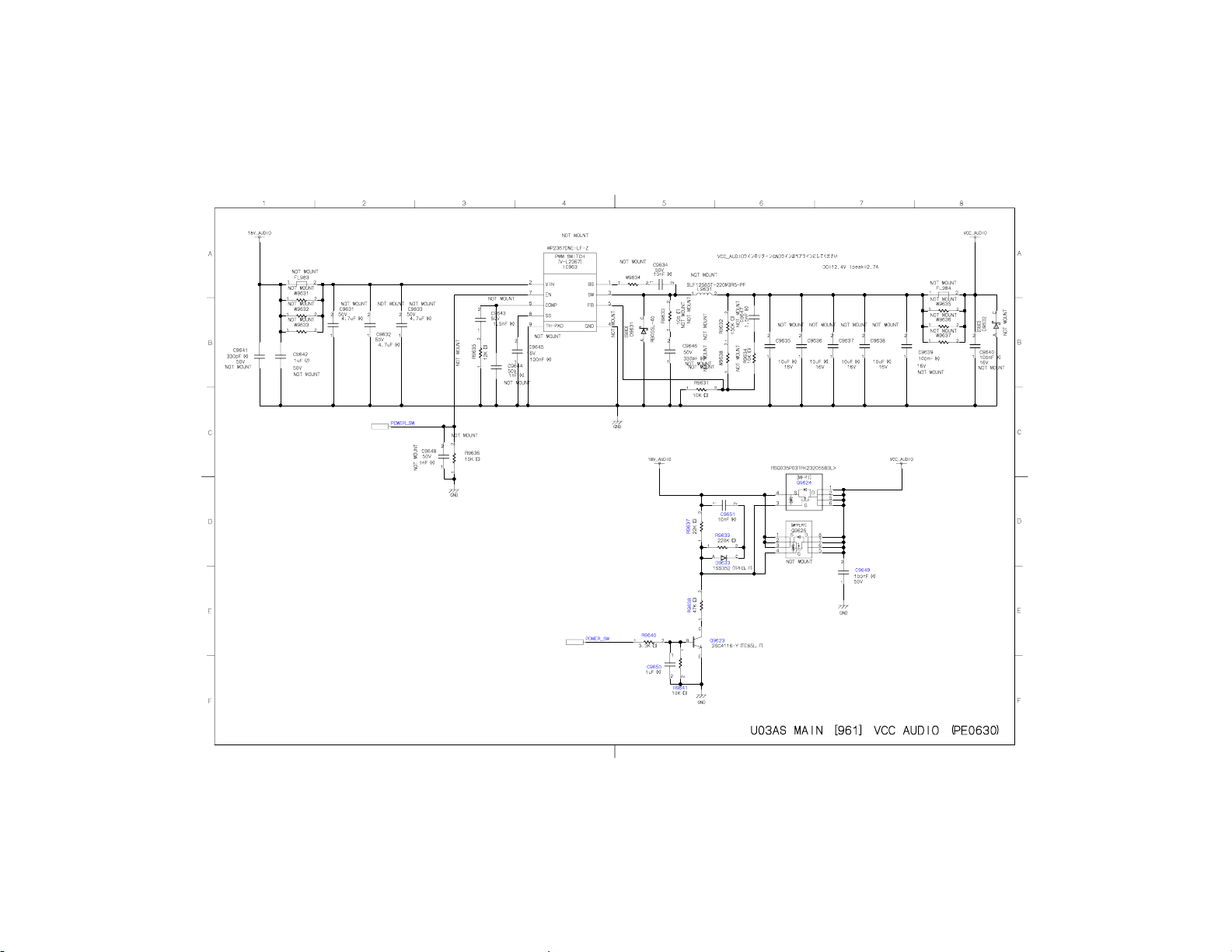
SCHEMATIC DIAGRAM
Precaution
WARNING: BEFORE SERVICING THIS CHASSIS, READ THE "X-RAY
RADIATION PRECAUTION" FOR DIRECT VIEW CTV ONLY, "SAFETY
PRECAUTION" AND "PRODUCT SAFETY NOTICE" OF THIS MANUAL.
CAUTION: The international hazard symbols " " in the schematic diagram
and the parts list designate components which have special characteristics
important for safety and should be replaced only with types identical to
those in the original circuit or specified in the parts list.
The mounting position of replacements is to be identical with originals.
Before replacing any of these components, read carefully the SAFETY
PRECAUTION and PRODUCT SAFETY NOTICE.
Do not degrade the safety of the receiver through improper servicing.
Note:
1. RESISTOR
Resistance is shown in ohm [K=1,000, M=1,000,000]. All resistors are 1/6 W and 5 %
tolerance carbon resistor, unless otherwise noted as the following marks.
1/2R : Metal or Metal oxide of 1/2 watt
1/2S : Carbon composition of 1/2 watt
1RF : Fuse resistor of 1 watt
10 W : Cement of 10 watt
K : ±10 %
G : ±2 %
F : ±1 %
2. CAPACITOR
Page 16

Unless otherwise noted in schematic, all capacitor values less than 1 are expressed in
µF, and the values more than 1 in pF.
All capacitors are ceramic 50 V, unless otherwise noted as the following marks.
= Electrolytic capacitor
= Mylar capacitor
3. The parts indicated with " " have special characteristics, and should be replaced with
identical parts only.
4. Voltages read with DIGITAL MULTI-METER from point indicated to chassis ground,
using a color bar signal with all controls at normal, line voltage at nominal AC volts.
5. Waveforms are taken receiving color bar signal with enough sensitivity.
6. Voltage reading shown are nominal values and may vary ±20 % except H.V.
Page 17
Page 18
Page 19
Page 20
Page 21
Page 22
Page 23
Page 24
Page 25
Page 26
Page 27
Page 28
Page 29
Page 30
Page 31
Page 32
Page 33
Page 34
Page 35
Page 36
Page 37
Page 38
Page 39

Page 40
Page 41

Page 42
Page 43
Page 44
Page 45
Page 46
Page 47
Page 48
Page 49

Page 50
Page 51

Page 52
Page 53

Page 54

Page 55
Page 56
Page 57
Page 58
Page 59

Page 60
Page 61
Page 62
Page 63
Page 64
Page 65
Page 66
Page 67
Page 68
Page 69
Page 70
Page 71
Page 72

Page 73
Page 74
Page 75

ADJUSTMENT
Service Mode
Entering to Service Mode
1. Set VOLUME to minimum and press
button once on remote control.
↓
↓
Service Mode display
2. Press button again and hold button down.
3. While holding the button, press MENU
button on TV set.
Page 76
Displaying the Adjustment Menu
Press MENU button on TV.
Service Mode
Press ↑ ↓ Press
Adjustment Mode
Page 77
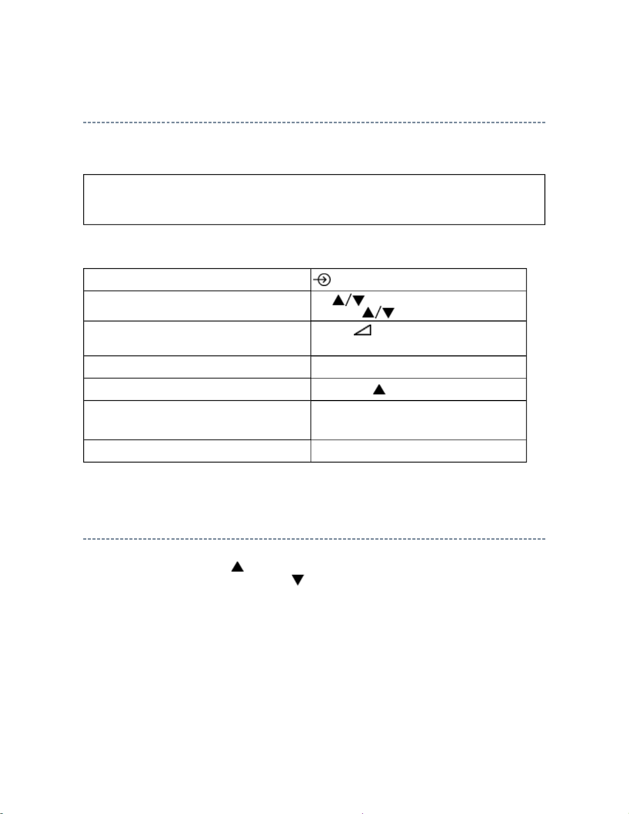
Key Function in the Service Mode
The following key entry during display of adjustment menu provides special functions.
CAUTION: Never try to perform initialization unless you have changed the
memory IC.
Test signal selection
Selection of the adjustment items
Change of the data value
Adjustment menu mode ON/OFF MENU button (on TV)
Initialization of the memory (IC152) CALL + CH button on TV
Automatic A/D Adjustment
(Component, Composite (PAL, NTSC), RGB)
Self diagnostic display ON/OFF 9 button
button (on remote control)
CH (on TV)
or MENU (on remote control)
Volume +/- (on TV)
or MENU RIGHT/LEFT (on remote control)
7 button
Selecting the Adjusting Item
Every pressing of MENU UP button in the service mode changes the adjustment items in
the order of table below. (MENU DOWN button for reverse order)
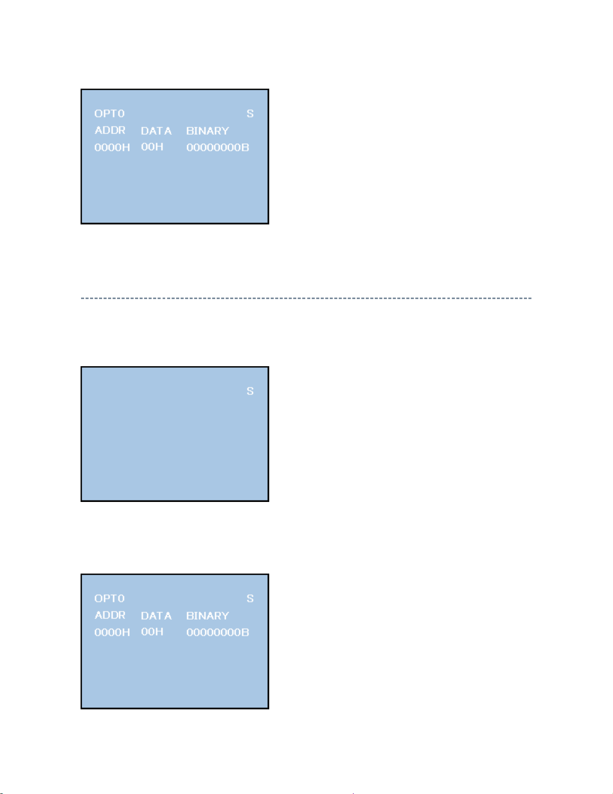
SETTING & ADJUSTING DATA
[ SERVICE MODE ]
ADJUSTING ITEMS AND DATA IN THE SERVICE MODE:
Note:
Page 78
The image system data of RCUT-BDRV is different by each image format.
N
The PAL value is indicated in the table.
ever adjust H.POS and V.POS except PAL/WIDE mode.
Item Name of adjustment
PLLW0 PLL WAIT TIME
PLLW1 PLL WAIT TIME
PLLW2 PLL WAIT TIME
PLLW3 PLL WAIT TIME
PLLW4 PLL WAIT TIME
PLLW5 PLL WAIT TIME
OPT1 TV SET OPTION 1
OPT2 TV SET OPTION 2
OPT3 TV SET OPTION 3
OPT4 TV SET OPTION 4 (PANEL OPT DATA FOR VENDOR)
OPT5 TV SET OPTION 5 (PANEL OPT DATA FOR INCH)
OPT6 TV SET OPTION 6 (HOTEL MODE)
OPT7 TV SET OPTION 7 (HOTEL MODE)
OPT8 TV SET OPTION 8 (HOTEL MODE)
TVOP TV SET OPTION
ID MODEL ID
BDWID BORDER WIDTH FOR EXACT SCAN
BDHIT BORDER HEIGHT FOR EXACT SCAN
VOLUX MAX VOLUME LIMITED
RCUT R CUT OFF
GCUT G CUT OFF
BCUT B CUT OFF
RDRV R DRIVE
GDRV G DRIVE
BDRV B DRIVE
Page 79

CNTX DTV DYNAMIC CONTRAST MAX FOR DTV DYNAMIC
CNTX DTV STANDARD CONTRAST MAX FOR DTV STANDARD
CNTX DTV MILD CONTRAST MAX FOR DTV MILD
CNTX DTV MOVIE CONTRAST MAX FOR DTV MOVIE
CNTX VIDEO DYNAMIC CONTRAST MAX FOR VIDEO DYNAMIC
CNTX VIDEO STANDARD CONTRAST MAX FOR VIDEO STANDARD
CNTX VIDEO MILD CONTRAST MAX FOR VIDEO MILD
CNTX VIDEO MOVIE CONTRAST MAX FOR VIDEO MOVIE
CNTX YPBPR HD DYNAMIC CONTRAST MAX FOR YPBPR HD DYNAMIC
CNTX YPBPR HD STANDARD CONTRAST MAX FOR YPBPR HD STANDARD
CNTX YPBPR HD MILD CONTRAST MAX FOR YPBPR HD MILD
CNTX YPBPR HD MOVIE CONTRAST MAX FOR YPBPR HD MOVIE
CNTX YPBPR SD STANDARD CONTRAST MAX FOR YPBPR SD STANDARD
CNTX YPBPR SD MILD CONTRAST MAX FOR YPBPR SD MILD
CNTX YPBPR SD MOVIE CONTRAST MAX FOR YPBPR SD MOVIE
CNTX HDMI PC DYNAMIC CONTRAST MAX FOR HDMI PC DYNAMIC
CNTX HDMI PC STANDARD CONTRAST MAX FOR HDMI PC STANDARD
CNTX HDMI PC MILD CONTRAST MAX FOR HDMI PC MILD
CNTX HDMI PC MOVIE CONTRAST MAX FOR HDMI PC MOVIE
CNTX HDMI HD DYNAMIC CONTRAST MAX FOR HDMI HD DYNAMIC
CNTX HDMI HD STANDARD CONTRAST MAX FOR HDMI HD STANDARD
CNTX HDMI HD MILD CONTRAST MAX FOR HDMI HD MILD
CNTX HDMI HD MOVIE CONTRAST MAX FOR HDMI HD MOVIE
CNTX HDMI SD DYNAMIC CONTRAST MAX FOR HDMI SD DYNAMIC
CNTX HDMI SD STANDARD CONTRAST MAX FOR HDMI SD STANDARD
CNTX HDMI SD MILD CONTRAST MAX FOR HDMI SD MILD
CNTX HDMI SD MOVIE CONTRAST MAX FOR HDMI SD MOVIE
CNTX ATV DYNAMIC CONTRAST MAX FOR ATV DYNAMIC
CNTX ATV STANDARD CONTRAST MAX FOR ATV STANDARD
CNTX ATV MILD CONTRAST MAX FOR ATV MILD
Page 80

CONTRAST MAX FOR ATV MOVIE
BRTC DTV DYNAMIC BRIGHTNESS CENTER FOR DTV DYNAMIC
BRTC DTV STANDARD BRIGHTNESS CENTER FOR DTV STANDARD
BRTC DTV MILD BRIGHTNESS CENTER FOR DTV MILD
BRTC DTV MOVIE BRIGHTNESS CENTER FOR DTV MOVIE
BRTC VIDEO DYNAMIC BRIGHTNESS CENTER FOR VIDEO DYNAMIC
BRTC VIDEO STANDARD BRIGHTNESS CENTER FOR VIDEO STANDARD
BRTC VIDEO MILD BRIGHTNESS CENTER FOR VIDEO MILD
BRTC VIDEO MOVIE BRIGHTNESS CENTER FOR VIDEO MOVIE
BRTC YPBPR HD DYNAMIC BRIGHTNESS CENTER FOR YPBPR HD DYNAMIC
BRTC YPBPR HD STANDARD BRIGHTNESS CENTER FOR YPBPR HD STANDARD
BRTC YPBPR HD MILD BRIGHTNESS CENTER FOR YPBPR HD MILD
BRTC YPBPR HD MOVIE BRIGHTNESS CENTER FOR YPBPR HD MOVIE
BRTC YPBPR SD DYNAMIC BRIGHTNESS CENTER FOR YPBPR SD DYNAMIC
BRTC YPBPR SD STANDARD BRIGHTNESS CENTER FOR YPBPR SD STANDARD
BRTC YPBPR SD MILD BRIGHTNESS CENTER FOR YPBPR SD MILD
BRTC YPBPR SD MOVIE BRIGHTNESS CENTER FOR YPBPR SD MOVIE
BRTC HDMI PC DYNAMIC BRIGHTNESS CENTER FOR HDMI PC DYNAMIC
BRTC HDMI PC STANDARD BRIGHTNESS CENTER FOR HDMI PC STANDARD
BRTC HDMI PC MILD BRIGHTNESS CENTER FOR HDMI PC MILD
BRTC HDMI PC MOVIE BRIGHTNESS CENTER FOR HDMI PC MOVIE
BRTC HDMI HD DYNAMIC BRIGHTNESS CENTER FOR HDMI HD DYNAMIC
BRTC HDMI HD STANDARD BRIGHTNESS CENTER FOR HDMI HD STANDARD
BRTC HDMI HD MILD BRIGHTNESS CENTER FOR HDMI HD MILD
BRTC HDMI HD MOVIE BRIGHTNESS CENTER FOR HDMI HD MOVIE
BRTC HDMI SD DYNAMIC BRIGHTNESS CENTER FOR HDMI SD DYNAMIC
BRTC HDMI SD STANDARD BRIGHTNESS CENTER FOR HDMI SD STANDARD
BRTC HDMI SD MILD BRIGHTNESS CENTER FOR HDMI SD MILD
BRTC HDMI SD MOVIE BRIGHTNESS CENTER FOR HDMI SD MOVIE
BRTC ATV DYNAMIC BRIGHTNESS CENTER FOR ATV DYNAMIC
Page 81

BRIGHTNESS CENTER FOR ATV STANDARD
BRTC ATV MILD BRIGHTNESS CENTER FOR ATV MILD
BRTC ATV MOVIE BRIGHTNESS CENTER FOR ATV MOVIE
COLC DTV DYNAMIC COLOR CENTER FOR DTV DYNAMIC
COLC DTV STANDARD COLOR CENTER FOR DTV STANDARD
COLC DTV MILD COLOR CENTER FOR DTV MILD
COLC DTV MOVIE COLOR CENTER FOR DTV MOVIE
COLC VIDEO DYNAMIC COLOR CENTER FOR VIDEO DYNAMIC
COLC VIDEO STANDARD COLOR CENTER FOR VIDEO STANDARD
COLC VIDEO MILD COLOR CENTER FOR VIDEO MILD
COLC VIDEO MOVIE COLOR CENTER FOR VIDEO MOVIE
COLC YPBPR HD DYNAMIC COLOR CENTER FOR YPBPR HD DYNAMIC
COLC YPBPR HD STANDARD COLOR CENTER FOR YPBPR HD STANDARD
COLC YPBPR HD MILD COLOR CENTER FOR YPBPR HD MILD
COLC YPBPR HD MOVIE COLOR CENTER FOR YPBPR HD MOVIE
COLC YPBPR SD DYNAMIC COLOR CENTER FOR YPBPR SD DYNAMIC
COLC YPBPR SD STANDARD COLOR CENTER FOR YPBPR SD STANDARD
COLC YPBPR SD MILD COLOR CENTER FOR YPBPR SD MILD
COLC YPBPR SD MOVIE COLOR CENTER FOR YPBPR SD MOVIE
COLC HDMI PC DYNAMIC COLOR CENTER FOR HDMI PC DYNAMIC
COLC HDMI PC STANDARD COLOR CENTER FOR HDMI PC STANDARD
COLC HDMI PC MILD COLOR CENTER FOR HDMI PC MILD
COLC HDMI PC MOVIE COLOR CENTER FOR HDMI PC MOVIE
COLC HDMI HD DYNAMIC COLOR CENTER FOR HDMI HD DYNAMIC
COLC HDMI HD STANDARD COLOR CENTER FOR HDMI HD STANDARD
COLC HDMI HD MILD COLOR CENTER FOR HDMI HD MILD
COLC HDMI HD MOVIE COLOR CENTER FOR HDMI HD MOVIE
COLC HDMI SD DYNAMIC COLOR CENTER FOR HDMI SD DYNAMIC
COLC HDMI SD STANDARD COLOR CENTER FOR HDMI SD STANDARD
COLC HDMI SD MILD COLOR CENTER FOR HDMI SD MILD
Page 82

COLOR CENTER FOR HDMI SD MOVIE
COLC ATV DYNAMIC COLOR CENTER FOR ATV DYNAMIC
COLC ATV STANDARD COLOR CENTER FOR ATV STANDARD
COLC ATV MILD COLOR CENTER FOR ATV MILD
COLC ATV MOVIE COLOR CENTER FOR ATV MOVIE
UVTT DTV DYNAMIC BASE BAND TINT FOR DTV DYNAMIC
UVTT DTV STANDARD BASE BAND TINT FOR DTV STANDARD
UVTT DTV MILD BASE BAND TINT FOR DTV MILD
UVTT DTV MOVIE BASE BAND TINT FOR DTV MOVIE
UVTT VIDEO DYNAMIC BASE BAND TINT FOR VIDEO DYNAMIC
UVTT VIDEO STANDARD BASE BAND TINT FOR VIDEO STANDARD
UVTT VIDEO MILD BASE BAND TINT FOR VIDEO MILD
UVTT VIDEO MOVIE BASE BAND TINT FOR VIDEO MOVIE
UVTT YPBPR HD DYNAMIC BASE BAND TINT FOR YPBPR HD DYNAMIC
UVTT YPBPR HD STANDARD BASE BAND TINT FOR YPBPR HD STANDARD
UVTT YPBPR HD MILD BASE BAND TINT FOR YPBPR HD MILD
UVTT YPBPR HD MOVIE BASE BAND TINT FOR YPBPR HD MOVIE
UVTT YPBPR SD DYNAMIC BASE BAND TINT FOR YPBPR SD DYNAMIC
UVTT YPBPR SD STANDARD BASE BAND TINT FOR YPBPR SD STANDARD
UVTT YPBPR SD MILD BASE BAND TINT FOR YPBPR SD MILD
UVTT YPBPR SD MOVIE BASE BAND TINT FOR YPBPR SD MOVIE
UVTT HDMI PC DYNAMIC BASE BAND TINT FOR HDMI PC DYNAMIC
UVTT HDMI PC STANDARD BASE BAND TINT FOR HDMI PC STANDARD
UVTT HDMI PC MILD BASE BAND TINT FOR HDMI PC MILD
UVTT HDMI PC MOVIE BASE BAND TINT FOR HDMI PC MOVIE
UVTT HDMI HD DYNAMIC BASE BAND TINT FOR HDMI HD DYNAMIC
UVTT HDMI HD STANDARD BASE BAND TINT FOR HDMI HD STANDARD
UVTT HDMI HD MILD BASE BAND TINT FOR HDMI HD MILD
UVTT HDMI HD MOVIE BASE BAND TINT FOR HDMI HD MOVIE
UVTT HDMI SD DYNAMIC BASE BAND TINT FOR HDMI SD DYNAMIC
Page 83
y
BASE BAND TINT FOR HDMI SD STANDARD
UVTT HDMI SD MILD BASE BAND TINT FOR HDMI SD MILD
UVTT HDMI SD MOVIE BASE BAND TINT FOR HDMI SD MOVIE
UVTT ATV DYNAMIC BASE BAND TINT FOR ATV DYNAMIC
UVTT ATV STANDARD BASE BAND TINT FOR ATV STANDARD
UVTT ATV MILD BASE BAND TINT FOR ATV MILD
UVTT ATV MOVIE BASE BAND TINT FOR ATV MOVIE
Factory preset data will be loaded after setting Model ID data.
(Refer to Initialization of Memory Data of IC152 and setting data of signal board.)
Adjusting the Data
Pressing of MENU RIGHT/LEFT button will change the value of data in the range from 00H
to FFH. The variable range depends on the adjusting item.
Setting TVOP
Enter to service mode and select menu of TVOP by pressing MENU UP or DOWN during
display of adjustment menu. After selecting TVOP, press MENU RIGHT or LEFT to set
WDT function to disable or enable as below.
TVOP FUNCTION DESCRIPTION 1 0 (Normal)
D5 (bit5) TV-Micon Watch Dog Timer (WDT) Disable Enable
Setting Panel Option Data
Panel option data is subject to OP4 and OP5.
Enter to service mode and select menu of OPT4 or OPT5 b
pressing P or P during
Page 84
display of adjustment menu. After selecting OPT4 or OPT5, press + or - to set OPT4
or OPT5 value as table below.
Panel option data
Series Model name Panel vendor OPT4 value OPT5 value
AV554D EU Digital 32AV554D SHARP 0x02 0x05
37AV554D LGD 0x01 0x06
42AV554D LGD 0x01 0x07
OPT4
Ex. OPT4 value 0x02 indicates that panel vendor is SHARP.
OPT4
Panel vendor LGD ----0001
SHARP ----0010
CMO ----0011
AUO PMVA----0100
AUO AMVA----0101
SAMSUNG----0110
IPS ----0111
D7
(bit7)
D6
(bit6)
D5
(bit5)
D4
(bit4)
D3
(bit3)
D2
(bit2)
D1
(bit1)
D0
(bit0)
OPT5
Ex. OPT5 value 0x05 indicates that panel size is 32.
OPT5
Size 26 ----0011
32 ----0101
37 ----0110
D7
(bit7)
D6
(bit6)
D5
(bit5)
D4
(bit4)
D3
(bit3)
D2
(bit2)
D1
(bit1)
D0
(bit0)
Page 85

42 ----0111
Backlight Status
Logic
Backlight Status
Check
Backlight Force
Twice On
Positive --1----Negative 0
Execute -1-----Unexecuted 0
Execute 1------Unexecuted 0
Convert from Bit (Binary) to Hex
The table for converting from bit (D7-D0) to hex (0x**).
BIT (Binary)
High nibble D7 D6 D5 D4
Low nibble D3 D2 D1 D0
HEX 0 0000
1 0001
2 001 0
3 0011
4 0 1 00
5 0 1 0 1
6 0 110
7 0 111
81000
91001
A10 1 0
B10 11
C1100
D110 1
Page 86

E1110
F1111
E.g. If Bit D7-0 = 0101 1010, Hex data is 0x5A.
Exit from Service Mode
Pressing POWER button to turn off the TV once.
Initialization of Memory Data of IC152 and Setting Data of Signal Unit
After replacing IC152 or signal board, the following initialization is required.
CAUTION: Never attempt to initialize the data unless IC152 has been
replaced.
Whenever using new signal board to the set, setting the Model ID data
according to Panel option data.
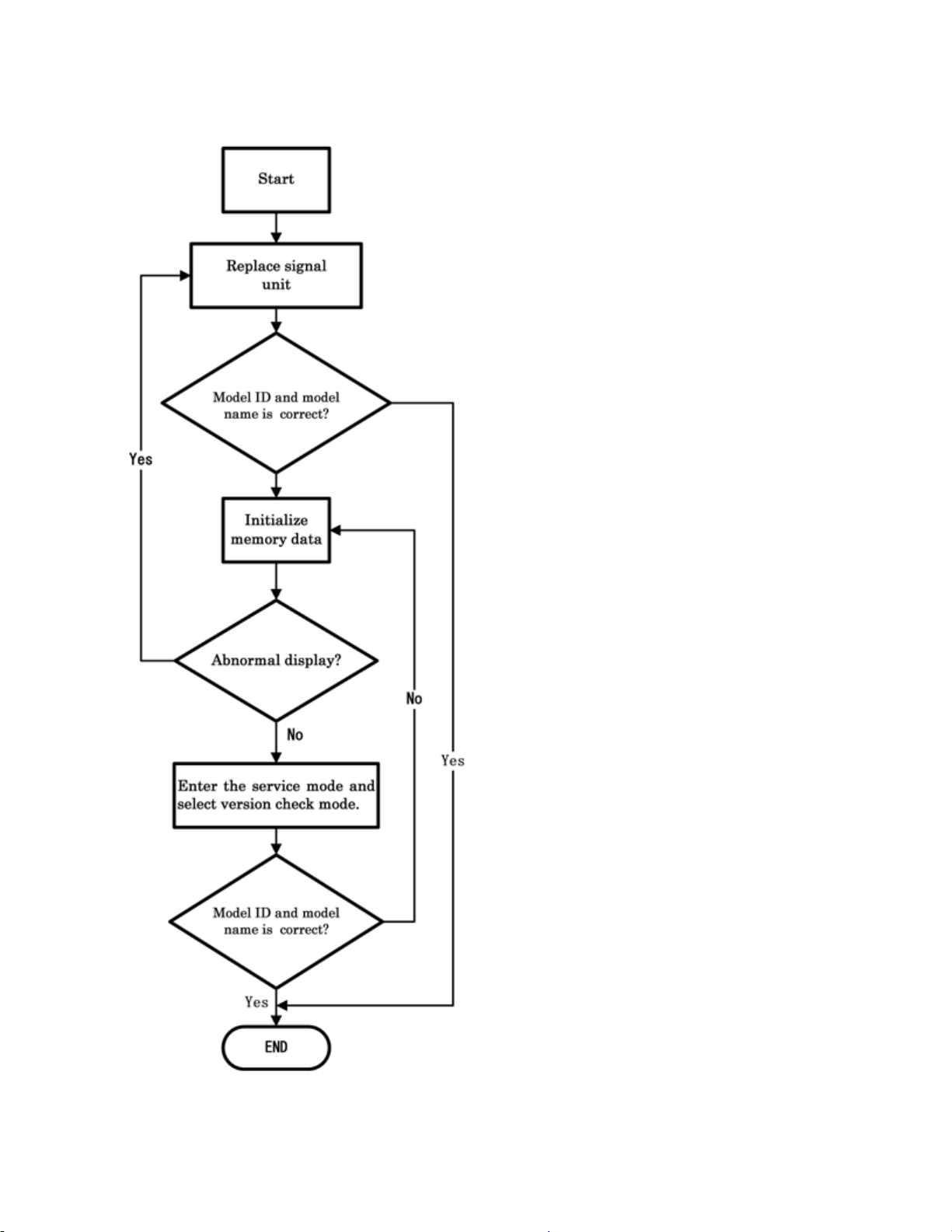
1) Enter the service mode.
2) Select menu of ID by pressing P or P during display of adjustment menu in the
service mode.
3) Change ID data into MODEL ID to initialize by pressing + or -, refer to table
below.
For example, if want to initialize 32AV555D, change MODEL ID into "0x01".
Note:
MODEL ID is hex value. For example, set value is not Decimal 11 but hex 11.
4) Press and hold the CALL button on the remote control, then press the CHANNEL
button on the TV.
Page 87
5) Initialization progress dialog including model name and panel vendor is shown.
Progress status is "WRITING".
6) Progress status is changed "OK" and power cycle (automatically). Then IC152
initialization has been completed.
7) Enter the service mode and select version check mode. Confirm if model name and
model id set is correct. If not, repeat steps 1) to 6).
Note:
In case initialization by setting wrong MODEL ID is done, there is a possibility of
abnormal display.
8) Set I2C check function of TVOP to enable.
9) Check the picture carefully. If necessary, adjust any adjustment item above.
Perform "Auto tune" on the owner's manual.
MODEL ID (HEX) Model name Panel vendor
0x01 32AV554D SHARP
0x02 37AV554D LGD
0x03 42AV554D LGD
0x04
0x05
0x06
0x07
0x08
0x09
0x10
0x11
0x12
0x13
0x14
0x15
Page 88
0x16
0x17
0x18
0x19
0x20
0x21
0x22
0x23
0x24
0x25
0x26
0x27
0x28
0x29
0x30
0x31
0x32
0x33
Initializing Data setting flowchart after replacing the Signal Unit
Page 89
Page 90
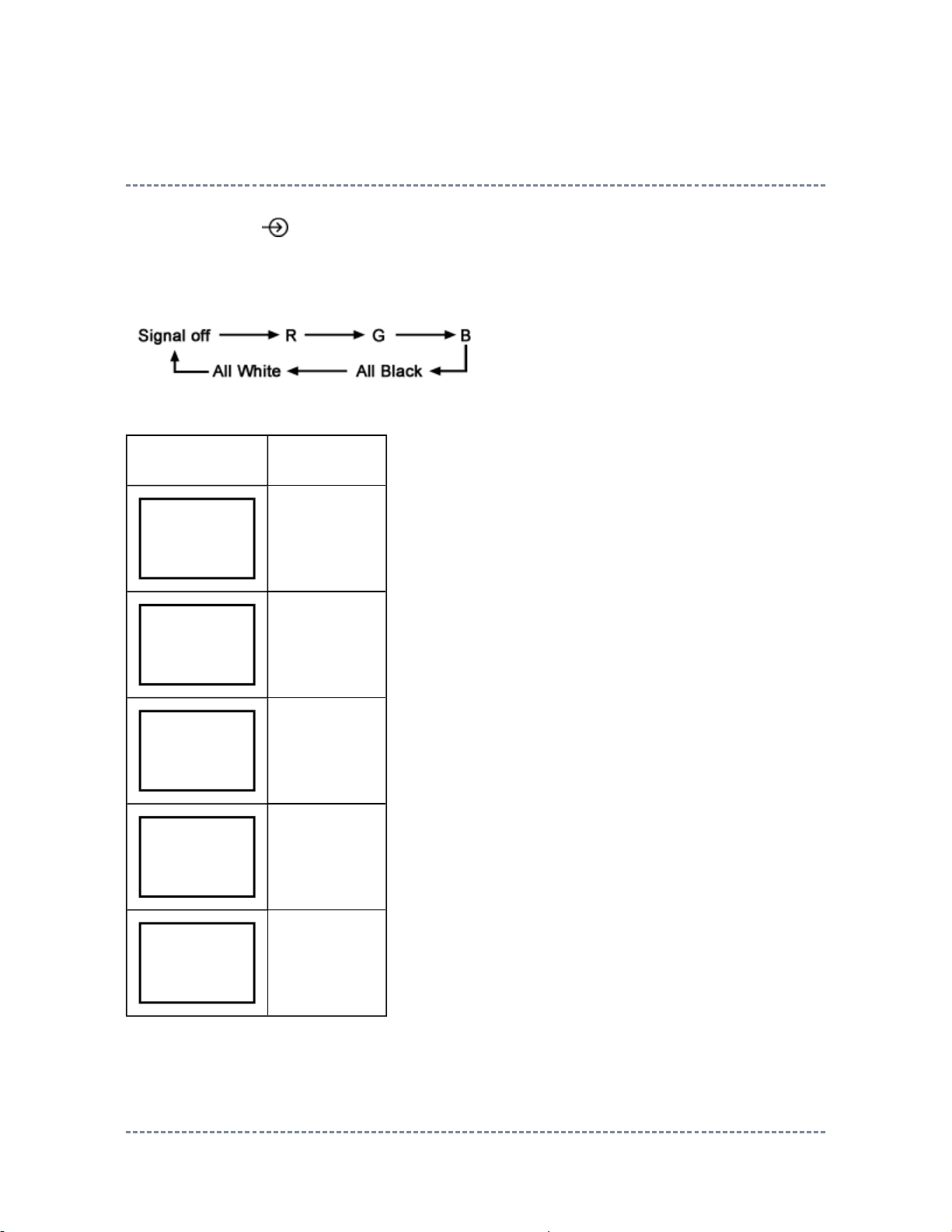
Test Signal Selection
Every pressing of button on the remote control changes the built-in test patterns on
screen as described below in Service Mode.
Picture Signal
Red raster
Green raster
Blue raster
All Black
All White
Self Diagnostic Function
Page 91
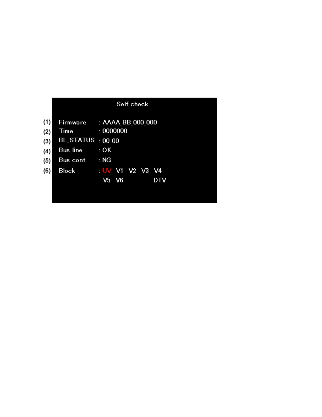
1. Press "9" button on remote control during display of adjustment menu in the service
N
mode. The diagnosis will begin to check if interface among IC's is executed properly.
2. During diagnosis, the following displays are shown.
* Self check display and Item are subject to the models.
(1) Firmware :
Version information of microprocessor
Series name (AAAA) and market area (BB) and software program version (000_000).
(2) Time : Total hour of turn the TV on. (Unit : H)
(3) BL_STATUS :
Counter for saving BackLight on error1.
This value is counted till 99 (Decimal).
(4) Bus line : -- "OK" is normal
SCL-GND (Red indication) : SCL-GND short circuit
SDA-GND (Red indication) : SDA-GND short circuit
SCL-SDA (Red indication) : SCL-SDA short circuit
(5) Bus cont : --- "OK" is normal.
G is abnormal (Red indication).
When the abnormal status is detected, type name of semiconductor is
indicated in red colour.
(6) Block
UV : TV reception mode
Page 92
V1 - V6:VIDEO 1-6 input mode
DTV : DTV mode
UV ATV
V1
(SCART (FULL))
V2
(SCART (S+AV))
V3
V4
V5 HDMI1
V6 HDMI2
V7 -V8 -V9 --
PC -YUV -DTV DTV
(Component)
(Composite)
1
2
3
4
Version Check Mode
1. Press "9" button twice on remote control during display of adjustment menu in the
service mode.
The version of main MPU will be checked.
2. During Version Check, the following displays are shown.
* Version check display and Item are subject to the models.
Page 93
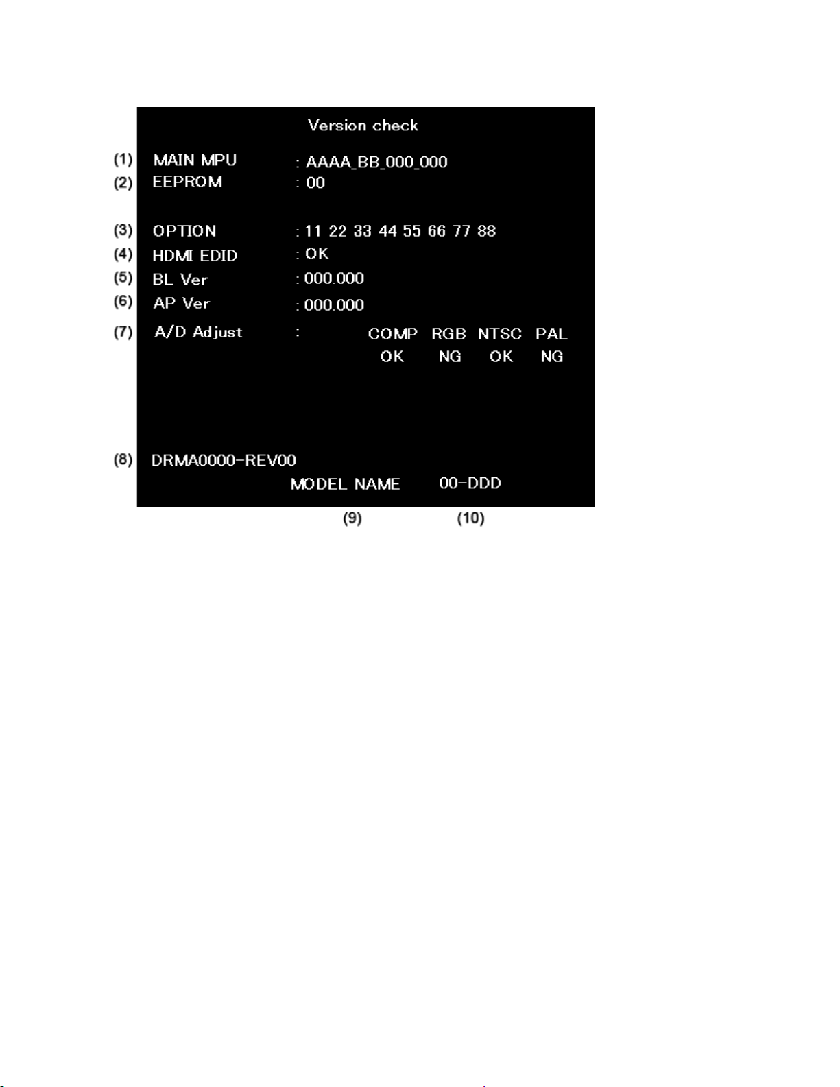
(1) MAIN MPU :
Version information of microprocessor
Series name and Code Program Version (5 figure number) and software program
version (000_000).
(2) EEPROM :
Version information of EEPROM : Display 1 byte data.
(3) OPTION :
Option information : Display eight numbers of 1 byte data.
(4) HDMI EDID :
EDID data check item.
OK : EDID data is enable.
NG : EDID data is disable.
(5) BL Ver
Version information of Boot Loader software as Toshiba release.
(6) AP Ver
Version information of Application software as Toshiba release.
(7) A/D Adjust
Page 94

A/D adjustment item.
--COMP:Component input
--RGB : RGB Signal (SCART input)
--NTSC :NTSC (60 Hz) SD signal (composite input).
--PAL : PAL (50 Hz) SD signal (composite input).
--OK :A/D adjustment set correctly.
--NG :A/D adjustment set incorrect.
(8) Memory Data Version
Version information of EEPROM.
DRMA**** means model number of EEPROM.
REV** means version of EEPROM.
(9) Model Name
Model name information (ascii code). : Display 8 byte data.
(10) LCD Panel Vendor information display
The following Panel Vendor (DDD) and screen size (00) and displayed.
Example : AUO-32 (1080p) indicates that Vendor is AUO and Screen Size is 32 inch
and Full HD panel.
Status Check Mode
1. Press "9" button thrice on remote control during display of adjustment menu in the
service mode.
The status of this model will be checked.
2. During Status Check, the following displays are shown.
* Status check display and Item are subject to the models.
Page 95
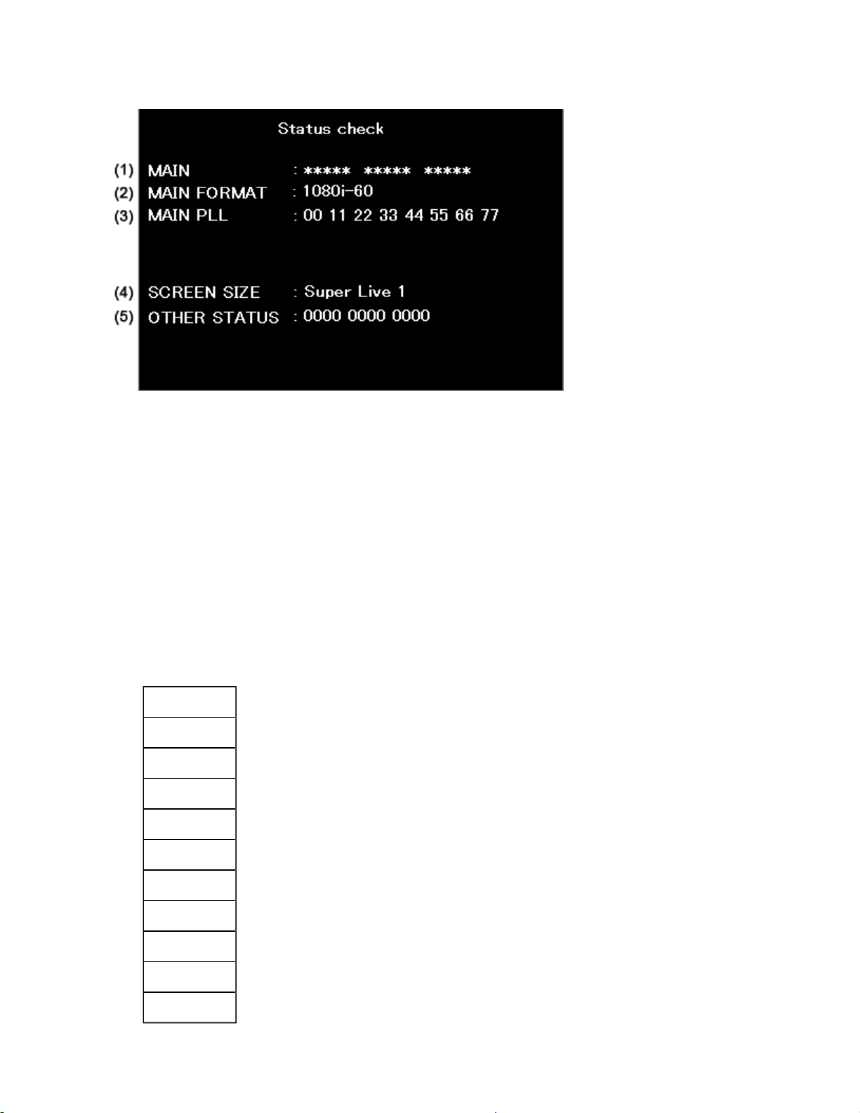
(1) MAIN :
Main source information :
Display RF position number (0 - 999) on the main screen, or Input Source
(EXT1/2/3/HDMI etc.)
(2) MAIN FORMAT :
Display Video format information
(3) MAIN PLL :
Main PLL information : Display 1 byte data at eight.
(4) SCREEN SIZE :
Display the screen size as follows.
Native
Wide
Super Live 2
Cinema 2
4:3
Super Live 1
Cinema 1
Subtitle
14:9
PC-Normal
PC-Wide
Page 96

Note:
Exact Scan is shown only when 1080p panel model and video input mode except pc.
(5) OTHER STATUS :
Other status information : Display three numbers of 2 byte data.
LED Indications
The Green and Red LEDs on the TV (at the bottom center of the TV) indicate the TV's
status, as described below.
z Red ON (solid) and Green OFF = The TV power cord is plugged in.
z Green ON (solid) only = The TV is operating.
z Green ON (solid) and Red ON = Active standby mode.
Page 97

SOFTWARE UPGRADE
Software Upgrade
1. Unplug AC Power.
2. Insert USB Flash memory containing software to TV set.
3. Plug AC Power.
4. Progress bar is shown on TV screen while upgrading.
"100 %" is shown when completed.
Never power off while upgrading.
5. Unplug AC Power.
6. Remove USB Flash memory.
7. Plug AC Power.
Page 98
PANEL IDENTIFICATION
Panel Identification
If the several panels are alternatively used in the same model without amending the model
name, the identification marking will be shown at the last digit of the set serial number on the
specification label on the back cover.
In servicing, do not alter the panel because several setting and parts are different.
Marking Panel Vendor Marking Panel Vendor Marking Panel Vendor
A AUO J S SHARP
B K SAMSUNG T
CCMO LLGD U
D M V
E N W
F P X
G Q Y
HIPS R Z
With this alternative use, some of key parts may differ and their combinations are
indicated with the suffix marking on the location number in the part list
(Miscellaneous).
e.g.
Location No. Part No. Description
B001A 75007869 LCD Panel, 32" LGD
B001B 75007870 LCD Panel, 32" AUO
MZ01A 75006036 LDVS Cable
MZ01B 75007893 LDVS Cable
Page 99

Page 100

PARTS LIST
Precaution
WARNING: BEFORE SERVICING THIS CHASSIS, READ THE "X-RAY
RADIATION PRECAUTION" FOR DIRECT VIEW CTV ONLY, "SAFETY
PRECAUTION" AND "PRODUCT SAFETY NOTICE" OF THIS MANUAL.
CAUTION: The international hazard symbols " " in the schematic diagram
and the parts list designate components which have special characteristics
important for safety and should be replaced only with types identical to
those in the original circuit or specified in the parts list.
The mounting position of replacements is to be identical with originals.
Before replacing any of these components, read carefully the SAFETY
PRECAUTION and PRODUCT SAFETY NOTICE.
Do not degrade the safety of the receiver through improper servicing.
Note:
z The part number must be used when ordering parts, in order to assist in processing, be
sure to include the Model number and Description.
z The PC board assembly with mark is no longer available after the end of the
production.
Abbreviations
Capacitors CD : Ceramic Disk
Resistors CF : Carbon film
OMF : Oxide Metal Film
PF : Plastic Film
 Loading...