

Page 1

FILE NO. 030-200004
SERVICE MANUAL
COLOUR TELEVISION
C00P Chassis
40WH08G,40WH08B
PRINTED IN JAPAN Jun., 1999 T
Page 2

CHAPTER 1 GENERAL ADJUSTMENTS
SAFETY INSTRUCTIONS........................................................................................................................................3
CRT ASSEMBLY REPLACEMENT AND MOUNTING .............................................................................................4
PICTURE TUBE COMPONENTS ADJUSTMENT.................................................................................................... 6
SERVICE POSITION................................................................................................................................................9
SERVICE MODE ....................................................................................................................................................10
DESIGN MODE ......................................................................................................................................................13
GENERAL ADJUSTMENTS
ELECTRICAL ADJUSTMENT ................................................................................................................................14
CONVERGENCE ADJUSTMENT ..........................................................................................................................22
SCREEN AND MIRROR ALIGNMENTS ................................................................................................................31
CIRCUIT CHECKS .................................................................................................................................................32
CHAPTER 2 SPECIFIC INFORMATIONS
SETTING & ADJUSTING DATA ..............................................................................................................................33
LOCATION OF CONTROLS ...................................................................................................................................34
CIRCUIT BLOCK DIAGRAM ..................................................................................................................................36
TABLE OF CONTENTS
MECHANICAL DISASSEMBLY ..............................................................................................................................37
CHASSIS AND CABINET REPLACEMENT PARTS LIST......................................................................................38
PC BOARDS BOTTOM VIEW.................................................................................................................................65
TERMINAL VIEW OF TRANSISTORS ...................................................................................................................80
SPECIFICA TIONS .................................................................................................................................................. 81
APPENDIX:
CIRCUIT DIAGRAM
– 2 –
Page 3

CHAPTER 1 GENERAL ADJUSTMENTS
SAFETY INSTRUCTIONS
WARNING: BEFORE SERVICING THIS CHASSIS, READ THE “X-RAY RADIATION PRECAUTION”, “SAFETY PRECAU-
TION” AND “PRODUCT SAFETY NOTICE” INSTRUCTIONS BELOW.
X-RAY RADIATION PRECAUTION
1. Excessive high voltage can produce potentially hazardous X-RAY RADIATION. To avoid such hazards, the high
voltage must not be above the specified limit. The nominal
value of the high voltage of this receiver is (A) kV at zero
beam current (minimum brightness) under a (C) V AC po wer
source. The high voltage must not, under any circumstances, exceed (B) kV.
Refer to table-1 for high voltage (A), (B) & AC voltage (C).
(See SETTING & ADJUSTING DATA on page 33)
Each time a receiver requires servicing, the high voltage
should be checked following the HIGH VOLTAGE CHECK
procedure in this manual. It is recommended that the reading of the high voltage be recorded as a part of the service
record. It is important to use an accurate and reliable high
voltage meter.
SAFETY PRECAUTION
WARNING : Service should not be attempted by any one unfamiliar with the necessary precautions on this receiver . The following
are the necessary precautions to be observed before servicing this chassis.
1. An isolation transformer should be connected in the power line between the receiver and the AC line before any service is
performed on the receiver.
2. Always discharge the picture tube anode to the CRT conductive coating before handling the picture tube. The picture tube
is highly evacuated and if broken, glass fragments will be violently expelled. Use shatter proof goggles and keep picture tube
away from the unprotected body while handling.
3. When replacing a chassis in the cabinet, always be certain that all the protective devices are put back in place, such as; nonmetallic control knobs, insulating covers, shields, isolation resistor-capacitor network etc.
2. The only source of X-RAY RADIATION in this TV receiver
is the picture tube. For continued X-RAY RADIATION protection, the replacement tube must be exactly the same
type tube as specified in the parts list.
3. Some part in this receiver have special safety-related characteristics for X-RAY RADIATION protection. For continued safety, parts replacement should be undertaken only
after referring to the PRODUCT SAFETY NOTICE belo w.
GENERAL ADJUSTMENTS
PRODUCT SAFETY NOTICE
Many electrical and mechanical parts in this chassis have special safety-related characteristics. These characteristics are
often passed unnoticed by a visual inspection and the protection afforded b y them cannot necessarily be obtained b y using
replacement components rated for higher voltage, wattage, etc. Replacement parts which have these special safety characteristics are identified in this manual and its supplements; electrical components having such features are identified by
the international hazard symbols on the schematic diagram and the parts list.
Before replacing any of these components, read the parts list in this manual carefully. The use of substitute replacement
parts which do not have the same safety characteristics as specified in the parts list may create shock, fire, X-ray
radiation or other hazards.
– 3 –
Page 4
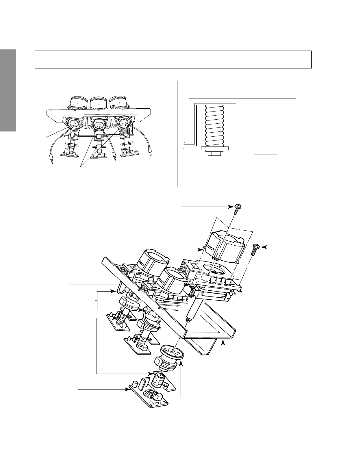
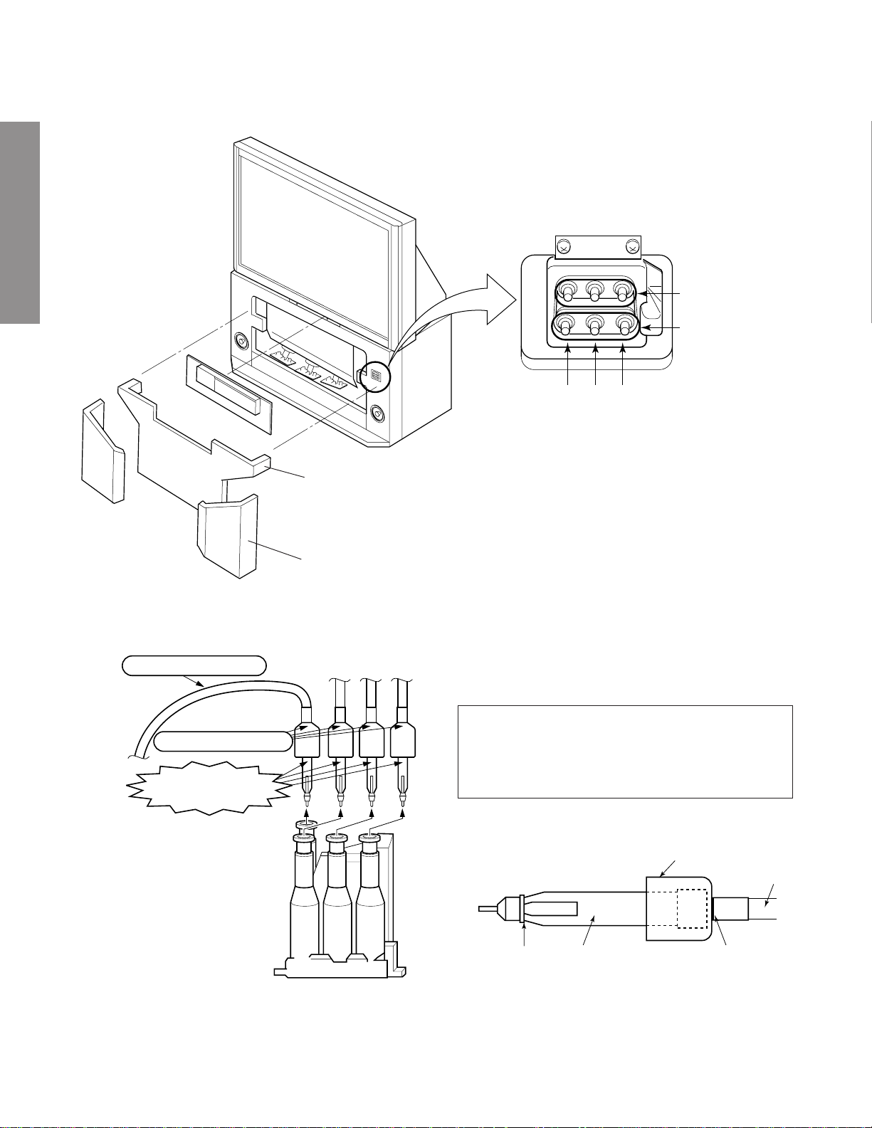
CRT ASSEMBLY REPLACEMENT AND MOUNTING
CAUTION : DO NOT LOOSEN THE HEX HEAD BOLTS WITH SPRINGS (12 PCS), BECAUSE THOSE ARE FOR
SEALING OF CRT COOLANT.
GENERAL ADJUSTMENTS
Attention Serviceman
The Hex Head
Bolts with
Springs. (see
sketch) used on
CRT assembly,
are “NOT”
Adjustment Screws
DO NOT LOOSEN-FLUID
LEAKAGE WILL OCCUR.
4 Screws
Lens Assembly
CRT Assembly
CRT Anode Cap Assembly
S.V.M. Coil
CRT DRIVE Board
4 Screws
CRT Mounting
Deflection Yoke and Conver Yoke
Lens and Neck Components View
– 4 –
Page 5
TO REMOVE CRT (Same procedure for R, G, B)
1. Remove CRT DRIVE Board, S. V. M. COIL and
DEF. YOKE from CRT.
2. Remove Lens Assembly.
3. Detach CRT Anode Cap from CRT.
4. Remove CRT Assembly from CRT Mounting.
CRT REPLACEMENT (Same procedure for R, G, B)
Reverse the removal procedures except the followings.
1. Anode Cable should be replaced with new one.
See "SERVICING PRECAUTIONS" shown below.
2. Install silicon (T461B) to the CRT, replace the Anode
cable and put enough silicon again on around the Anode Cap as illustrated.
CAUTION: Align the Anode cable as illustrated on page
4.
ADJUSTING PROCEDURE IN REPLACING CRT
1. R.G.B. CUTOFF (SCREEN VR) ADJUSTMENT (page 6.)
2. R.G.B. FOCUS ADJUSTMENT (page 6.)
3. PICTURE TILT ADJUSTMENT (page 7.)
4. USER CONVERGENCE CENTER CHECK
(Refer to owner's manual.)
5. CENTERING ADJUSTMENT (page 7.)
6. CONVERGENCE ADJUSTMENT (page 22.)
7. WHITE BALANCE ADJUSTMENT (page 14.)
Adjustments are complete.
Anode Cap
GENERAL ADJUSTMENTS
Silicon
(On shaded area)
TSE3843W #23960136
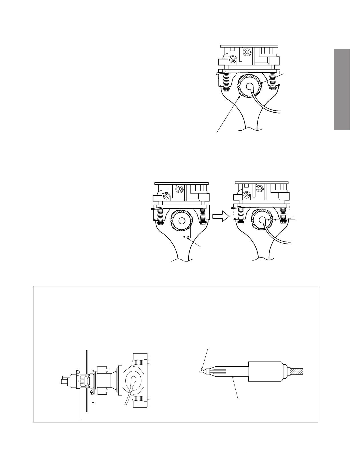
SERVICING PRECAUTIONS
■ Do not use a magnetized screw driver for screws
of Deflection Yoke and Velocity Modulation Coil to
avoid magnetization of electron gun.
Magnetization of electron gun will degrade basic
function and result in unbalance of right and left
shift of user static convergence, and result in no
variable quantity.
2 ~ 5 mm
15 ~ 25 mm
■ When replacing the anode cap assembly (CRT) or
anode lead assembly (F.B.T.), remove the anode
lead holder from old one and attach the holder
again to new anode lead.
■ Check the point of anode lead in a straight
line, if it is winding, please revise it.
Screw
for D.Y
Screw for SVM coil
Anode lead holder
– 5 –
Page 6
WARNING: BEFORE SERVICING THIS CHASSIS, READ THE "X-RAY RADIATION PRECAUTION", "SAFETY PRE-
CAUTION" AND "PRODUCT SAFETY NOTICE" ON PAGE 3 OF THIS MANUAL.
PICTURE TUBE COMPONENTS ADJUSTMENT
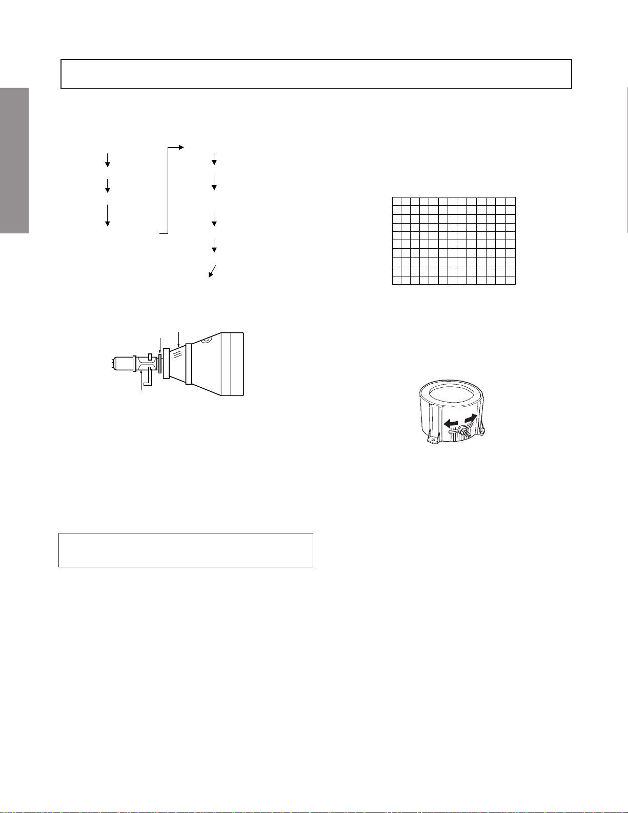
ADJUSTING PROCEDURE IN REPLACING CRT
Cutoff
Lens focus
Electrical focus
GENERAL ADJUSTMENTS
Yoke horizontal
DESCRIPTION OF NECK COMPONENTS
S.V.M. COIL
1 Deflection yoke and convergence yoke.
The position on the neck is required most front (CRT funnel side) and the screw is fastened after rotating yoke
adjusting picture tilt.
2 Centering magnet
After adjusting picture tilt, picture position is finally fixed
by this magnet.
In order to get maximum margin of user convergence control for center of screen, this magnet have to be used for
center convergence adjustment.
PREPARATION
Operate the receiver for at least 5 minutes.
R, G, B CUTOFF (SCREEN VR) ADJUSTMENT
1. Adjust before replace the screen assembly.
2. Set user control to reset position.
CONTRAST → Max
(
BRIGHTNESS, COLOR, TINT → Center.
3. Call up the adjustment mode display, then select the
item RCUT.
4. Adjust the data of items RCUT, GCUT, and BCUT to
"40H".
5. Press the -/-- ("Info") button on Remote. (Y-MUTE : ON)
6. Gradually rotate R, G and B screen volume of FOCUS
PAC clockwise or counterclockwise until the raster
appears slightly on the CRT through the each lens, and
leave them.
(Lookin to the lens in order to check the raster.)
7. Press the -/-- ("Info") button on Remote. (Return to Normal)
Picture)
2
User convergence center check
Centering (PAL)
Convergence adjustment
(PAL/NTSC)
White balance
Sub bright adjustment
End
1
RGB FOCUS ADJUSTMENT
1. Call-up the adjustment mode (see page 10)
2. Press a b utton on the remote controller in order to display
the internally-generated black cross-hatch (See TEST
SIGNAL SELECTION on page 11.)
3. Expose only RED by cover ing the GREEN and BLUE
lenses with caps.
4. Loosen the RED lens fixing screws (refer to Fig. a), and
adjust the RED lens focus to obtain the sharpest point
while observing the middle and peripheral sections of the
screen.
Fig. a
5. Use the focus VR of “R” of the focus pac k in order to adjust
the electric focus in the middle and peripheral sections of
the screen to its sharpest level.
6. Check the RED focus of the whole screen and if necessary
repeat steps 4 and 5.
7. Fix the RED lens by tightening its fixing screws.
8. Expose only GREEN by covering the RED and BLUE
lenses with caps.
9. Display the internally-generated black cross-hatch signal.
10. Adjust the GREEN lens focus on the left border of the
screen to its sharpest level, then check the focus on the
right border, and if it is at its sharpest level, fix it in that
)
position by tightening the lens screws.
(1) If the horizontal line toward the right border is red-
flared, turn the lens screw slightly right in order to
balance it with the left border. (After adjustment, the
left border tends to be slightly green-flared, and the
right border tends to be slightly red-flared.)
(2) If the horizontal line toward the right border is green-
flared, turn the lens screw slightly left in order to
balance it with the left border. (After adjustment, the
left border tends to be slightly red-flared, and the
right border tends to be slightly green-flared.)
– 6 –
Page 7
Note: The aim of the abov
for the Green lens focus is to obtain the best lens focus
after 2 - 3 hours of warming up taking into account the
focus drift; it applies if the war ming up time before the
adjustment is less than 30 minutes. (The horizontal line
in the screen middle section tends to be slightly redflared.)
e-descr
ibed adjustment procedure
Note: Keep in mind that only the BLUE electric focus is ad-
justed with the black cross-hatch.
18. Check the BLUE focus of the whole screen and if necessary repeat steps 17 and 19.
19. Fix the BLUE lens by tightening its fixing screws.
In case of warming up of more than 2 hours under a condition
that the large anode current is running through the projection
tube so that for example the all-white pattern appears, adjust
to obtain the sharpest focus while observing the whole screen
like in the RED case.
11. Use the focus VR of “G” of the focus pack in order to adjust the electric focus in the middle section of the screen
to its sharpest level.
Note: Nor mally the most clearly visible point of the scanning
line is the sharpest point of the Green focus, howev er as
the characteristics vary depending on the projection tube,
the sharpest focus points of the vertical and horizontal
lines may not match each other , thus when you turn the
focus VR, if the picture tends to be tremendously unstable
(rolls horizontally or vertically), adjust the balance of the
vertical and horizontal lines to its best position.
12. Check the GREEN focus of the whole screen and if
necessary repeat steps 10 and 11.
13. Fix the GREEN lens by tightening up its fixing screws.
14. Expose only BLUE by covering the RED and GREEN
lenses with caps.
15. Display the internally-generated black cross-hatch.
16. Loosen the BLUE lens fixing screws (refer to Fig. a), and
adjust the BLUE lens focus while observing the middle
and peripheral screen sections.
17. Use the focus VR of “B” of the f ocus pack in order to adjust
the focus in the middle section of the screen to its sharpest
level.
(The point of the Blue focus becomes sharpest when the
brightness level of BLUE is lowest, the cross-hatch is
clearly visible.)
TILT ADJUSTMENT
Rotate R, G, B deflection yoke so that picture becomes horizon, then fasten screw.
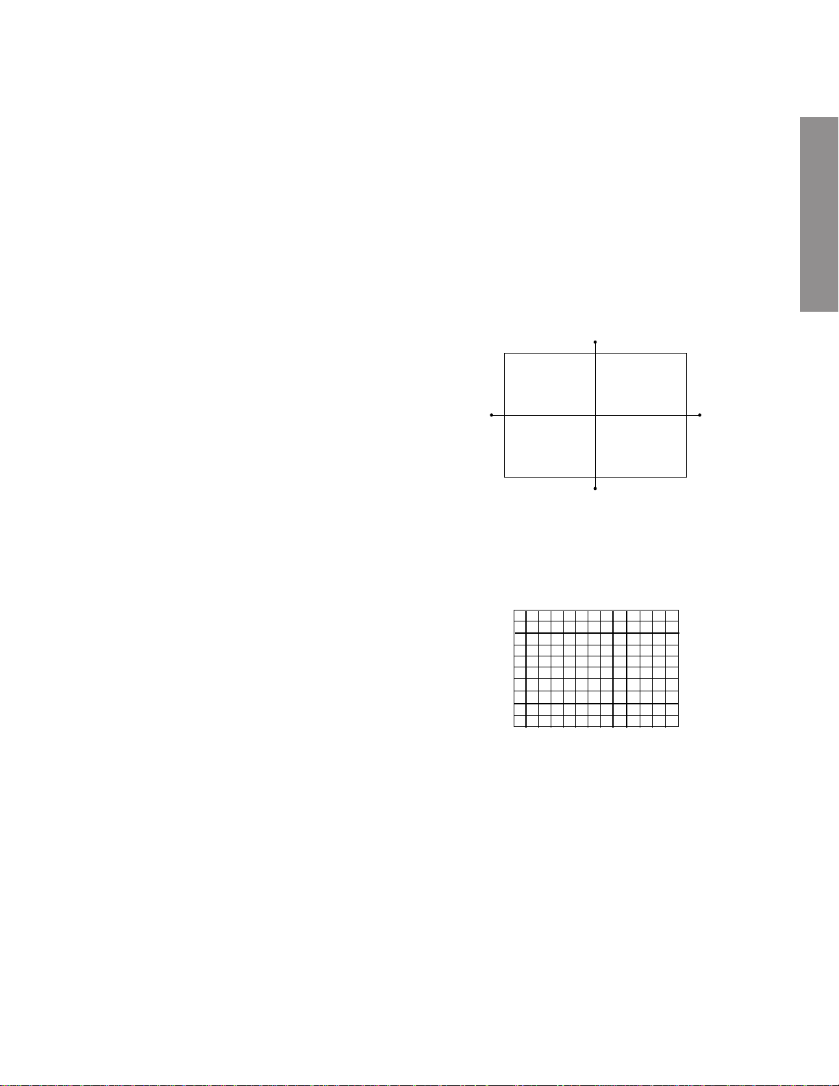
CENTERING ADJUSTMENT
1. Stretch a thread between two center of screen edge
(top and bottom, left and right).
2. Select the adjustment mode. (See page 10.)
3. Press TV/VIDEO button on the Remote Control to displa y
the black cross-hatch.
GENERAL ADJUSTMENTS
4. Adjust G centering magnet so that the cross-hatch pattern center comes to screen center.
5. Perform HEIGHT adjustment . (See page 14.)
6. Perform WIDTH adjustment. (See page 14.)
7. Check whole quality of green line.
8. Adjust R, B centering magnet so that the cross-hatch pattern center comes to screen center.
– 7 –
Page 8
LOCATION OF SCREEN AND FOCUS VR'S
To remove the Speaker grille and Front panel.
GENERAL ADJUSTMENTS
SCREEN VR
FOCUS VR
Front panel
Speaker grille
REPLACEMENT OF HIGH VOLTAGE CABLE
ANODE LEAD
RUBBER BOOT
LEAD HOLDER
B
1. When replacing Anode Lead or Anode Cap with new
one, remove Lead Holder from old lead as shown in
figure below , and put it on new lead. Do not throw awa y
Lead Holder.
NOTE : THE LEAD HOLDER IS ATTACHED TO
TP A5007 (Z450), BUT IS NO T A TTACHED TO
ANODE LEAD AND ANODE CAP. RUBBER
BOOT IS ATTA CHED TO ANODE LEAD AND
ANODE CAP.
RG
Fig. a
Z450 TPA5007
– 8 –
2. Detaching Lead Holder
LOCK
LEAD HOLDER
RUBBER BOOT
Fig. b
OLD
ANODE LEAD
or
ANODE CAP
Cut here rubber boot
and lead together to
detach Lead Holder.
Page 9
WARNING: BEFORE SER VICING THIS CHASSIS , READ THE "X-RAY RADIA TION PRECA UTION", "SAFETY PRECAU-
TION" AND "PRODUCT SAFETY NOTICE" ON PAGE 3 OF THIS MANUAL.
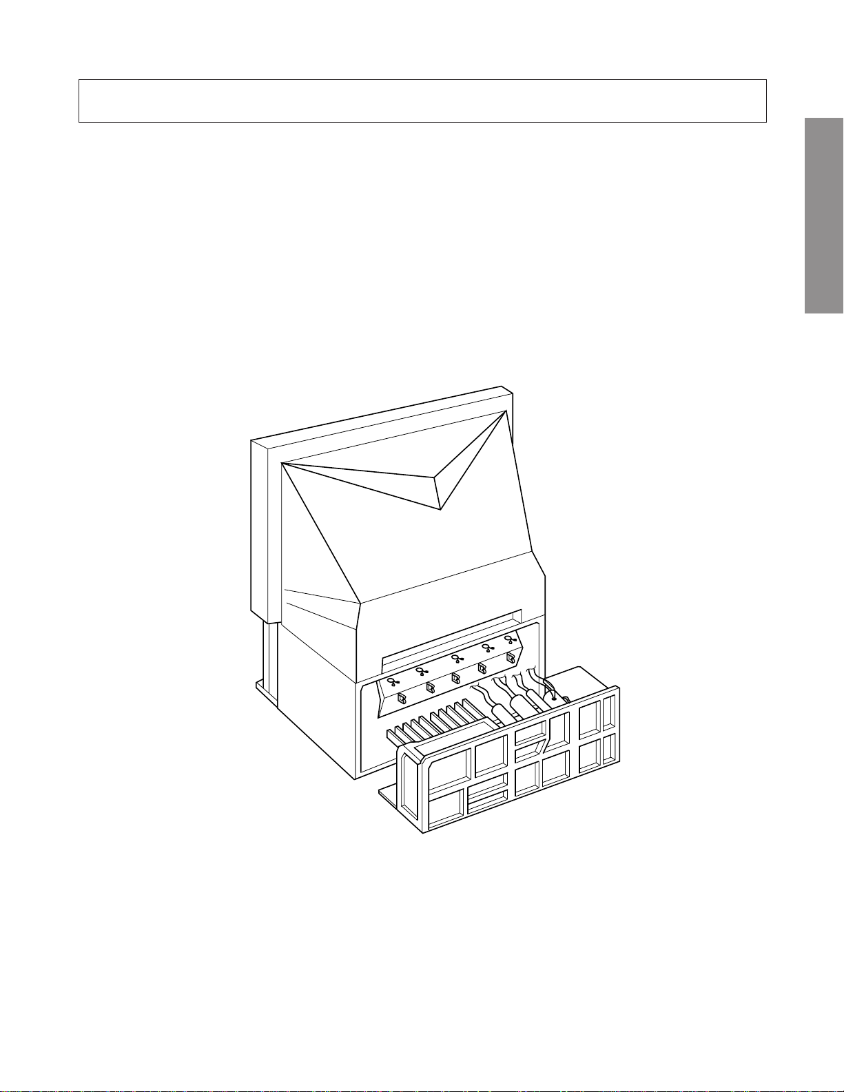
SERVICE POSITION
In order to assure the performance, processed wires shall be replaced after the repair work.
Work procedures are as follows:
1. Remove the back board.
2. Remove lead wires.
3. Draw out the chassis.
4. Rest the chassis against the back cabinet, chassis as shown bellow.
After repair work finished, replace it in the opposite procedure.
GENERAL ADJUSTMENTS
– 9 –
Page 10
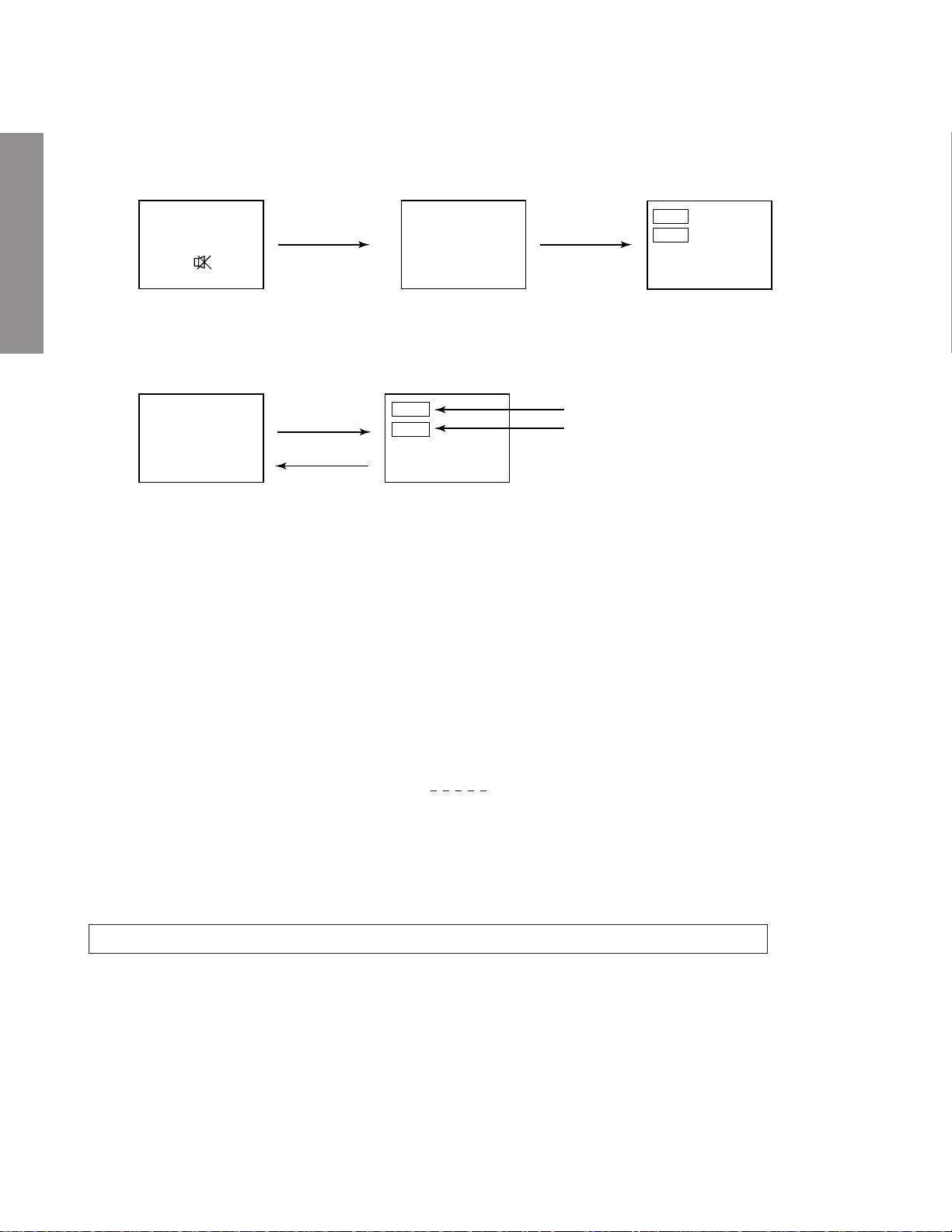
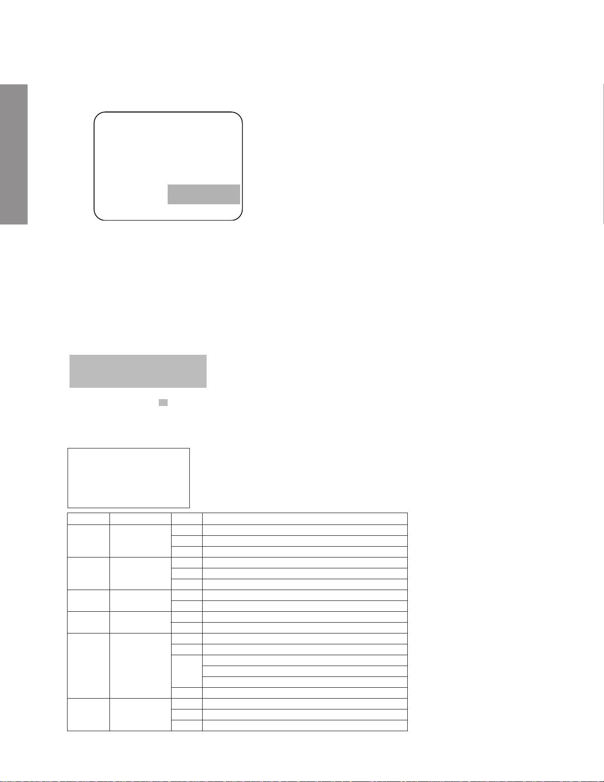
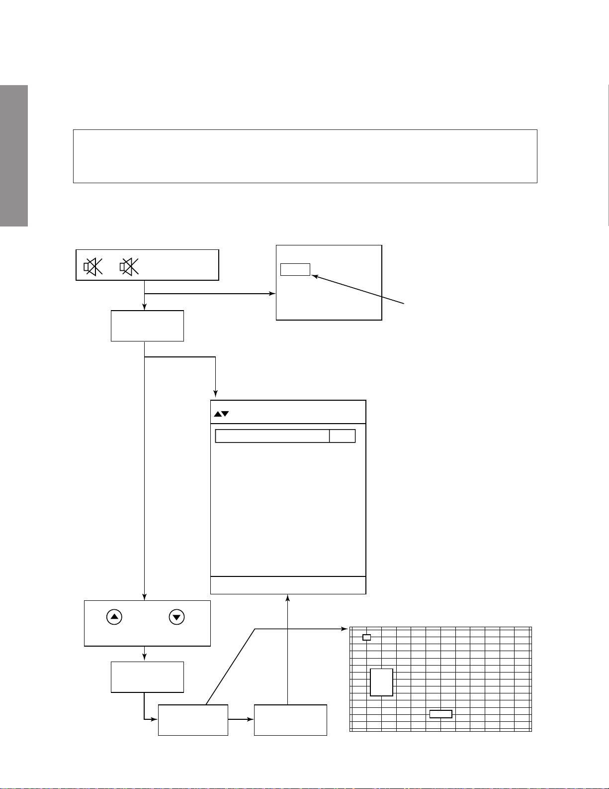
1. ENTERING TO SERVICE MODE
1) Press o button once on
Remote Control.
SERVICE MODE
2) Press o button again to
keep pressing.
3) While pressing the o button,
press MENU button on TV set.
or Sound Mute
GENERAL ADJUSTMENTS
2. DISPLAYING THE ADJUSTMENT MENU
1) Press MENU button on TV.
Service mode
3. KEY FUNCTION IN THE SERVICE MODE
The following key entry during display of adjustment menu provides special functions.
Screen adjustment mode ON/OFF: -/-- ("Info") button (on Remote)
Test signal selection : a button (on Remote)
Selection of the adjustment items : Channel s/t (on TV or Remote)
Change of the data value : Volume ; +/– (on TV or Remote)
Adjustment menu mode ON/OFF : MENU button (on TV)
Initialization of the memory (QA02) : CALL + Channel button on TV (s)
Reset the count of operating protect
circuit to “00”: CALL + Channel button on TV (t)
“RCUT” selection : 1 button
“GCUT” selection : 2 button
“BCUT” selection : 3 button
“SCNT” selection : 4 button
“COLC” selection : 5 button
“TNTC” selection : 6 button
Convergence adj : YELLOW button
Self diagnostic display ON/OFF : 9 button
Item
Data
(Service mode display)
Adjustment mode
S
Press
Press
Item
Data
S
Color thickness correction
note: Displayed differently as shown below, de-
pending on the setting of the receiving color
system.
COLP (PAL)
COLC (NTSC)
COLS (SECAM)
CAUTION : Never try to perform initialization unless you have changed the memory IC.
– 10 –
Page 11
4. SELECTING THE ADJUSTING ITEMS
1) Every pressing of CHANNEL s button in the service mode changes the adjustment items in the order of table-2.
(t button for reverse order)
Refer to table-2 for preset data of adjustment mode.
(See SETTING & ADJUSTING DATA on page 33)
5. ADJUSTING THE DATA
1) Pressing of VOLUME ; +/– button will change the value of data in the range from 00H to FFH. The variable
range depends on the adjusting item.
6. EXIT FROM SERVICE MODE
1) Pressing POWER button to turn off the TV once.
■ INITIALIZATION OF MEMORY DATA OF QA02
After replacing QA02, the following initialization is required.
1. Enter the service mode, then select any register item.
2. Press and hold the CALL button on the Remote, then press the CHANNEL s button on the TV. The initialization of QA02 has
been complated.
3. Check the picture carefully. If necessary, adjust any adjustment item above.
Perfor m “Auto search Memory” on the owner’s manual.
CAUTION: Never attempt to initialize the data unless QA02 has been replaced.
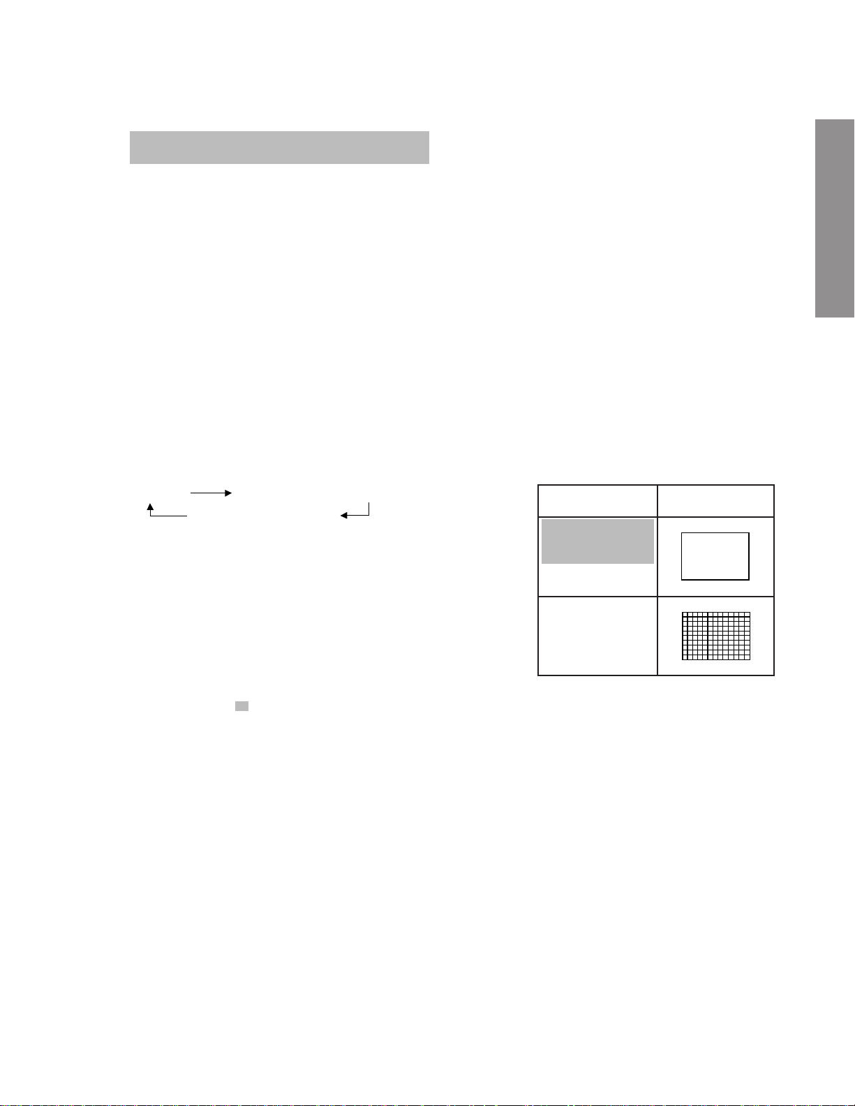
7. TEST SIGNAL SELECTION
1) Every pressing of a button on the Remote Control changes the built-in test patterns on screen as described below
in SERVICE MODE.
Signal off
NTSC signals (5 patterns)
PAL signals (5 patterns)
Signals Picture
• Red raster
• Green raster
• Blue r aster
• All White
• Black cross-hatch
GENERAL ADJUSTMENTS
The signals marked with are not usable to display in the Test signal for some model.
*
– 11 –
Page 12
8. SELF DIAGNOSTIC FUNCTION
1) Press “9” button on Remote Control during display of adjustment menu in the service mode.
The diagnosis will begin to check if interface among IC’s are executed properly.
2) During diagnosis, the following displays are shown.
<SELF CHECK>
1
2300****
2
TIME : 000000
3
POWER : 00
4
BUS CONT : OK
5
BLOCK : UV V1 V2 V3
QV01
GENERAL ADJUSTMENTS
1 Part number of microcomputer (QA01)
2 Total hour of turn the Power on. (unit: hour)
3 Operation number of protecting circuit ----“00” is nor-
mal.
When indication is other than “00”, overcurrent apts to
flow, and circuit parts may possibly be damaged.
4 BUS CONT ----“OK” is normal.
When indication shows “Q uuu (Green: OK, Red:
NG)”, the device with the number ma y possibly be damaged.
5 BLOCK
UV : TV reception mode
V1 : VIDEO 1 input mode (a1)
V2 : VIDEO 2 input mode (a2)
V3 : VIDEO 3 input mode (a3)
Indicated color of mode now selected : Green and Red
Indicated color of other modes : White
Green :Normal
Red : The microcomputer operates to provide judgement
of no video signal. The red color is still indicated
though the signal is input, failure may e xist in input
signal line including QV01.
QV01 : In case of indication green ---Normal
In case of indication red with input signal---Failure may exist in output line including QV01.
The items marked with are not usable to display in the SELF DIAGNOSTIC FUCTION for some model.
*
3) Press "9" button on Remote Control during display of selfcheck display as above, the selfcheck screen for EPG/TEXT
unit as shown below is displayed. (This function is only 40WH08G (EPG model).
SELFCHECK
EPG/TEXT
QF01 XXX QF10 XXX
QF02 XXX QF03 XXX
QF04 XXX QF05 XXX
Part No.
QF01
QF10
QF02
QF03
QF04
Part Name
MEGATEXT
DRAM
SUB-MICOM
PROGRAM
FLASH-ROM
DATA
FLASH-ROM
XXX
ERR
00
20
00
18
20
02
04
ERR
xxyy
ERR
00
A4
Contents
MEGATEXT plus SDA5275 access failed
Unknown
MEGATEXT plus SDA5275-3P C02-22
no DRAM
8 Mbit DRAM (2k-refresh type 16 Mbit DRAM)
16 Mbit DRAM (4k-refresh type 16 Mbit DRAM)
C161RI Version BB step
C161RI Version AA step
ROM access failed
Subsystem Version xx.yy
FLASH-ROM access failed
no FLASH-ROM
AM29F040 (AMD, 4Mbit)
MBM29F040C (Fujitsu, 4Mbit)
MX29F040 (Macronix, 4Mbit)
Unknown 4Mbit FLASH-ROM
EEPROM access failed
No EEPROM
8kbit EEPROM
QF05
EEPROM
FF
ERR
00
12
– 12 –
Page 13

1. ENTERING TO DESIGN MODE
1) Select the Service mode.
DESIGN MODE
2) While pressing CALL button on Remote
and press MENU button on TV.
3) Press MENU button on TV.
S D
(Design mode) (Adjustment mode)
When QA02 is initialized, items “OPT0” and “OPT1” of DESIGN MODE are set to the data of the representative model of this
chassis family.
Therefore, because ON-SCREEN specification remains in the state of the representative of model. This model is required to
reset the data of items “OPT0” and “OPT1”.
2. SELECTING THE ADJUSTING ITEMS
Every pressing of CHANNEL t button in the design mode changes the adjustment items in the order of table-3.
(s button for reverse order)
Refer to table-3 for data of design mode.
(See SETTING & ADJUSTING DATA on page 33)
3. ADJUSTING THE DATA
Pressing of VOLUME s or t button will change the value of data.
Press
Press
ITEM
DATA
GENERAL ADJUSTMENTS
– 13 –
Page 14
PAL
ELECTRICAL ADJUSTMENT
ITEM ADJUSTMENT PROCEDURE
WIDTH
(WID)
GENERAL ADJUSTMENTS
HEIGHT
(HIT)
1. Select picture size WIDE mode.
2. Call up the adjustment mode display, and press the TV/VIDEO
button on the remote untill the white cross dot pattern appears on
the screen.
3. Press the CHANNEL s or t button to select the item WID and
press the VOLUME s or t button to get the pictuer so the left and
right edges of rester begin to lack.
4. Press the VOLUME s or t to advance the data 13 steps.
* CAUTION
"WID" data don't adjust other picture size, only WIDE mode.
1. Call up the adjustment mode display, then select the item HIT.
2. Press the VOLUME s or t button to get the picture so the top of
raster begins to lack.
3. Press the VOLUME s button to advance the data by following steps.
WIDE: 11 steps
Super Live: 13 steps
CINEMA: 21 steps
Sub Title: 17 steps
* CAUTION
First adjust WIDE mode next other.
Note : Check the vertical picture position is correct.
ITEM ADJUSTMENT PROCEDURE
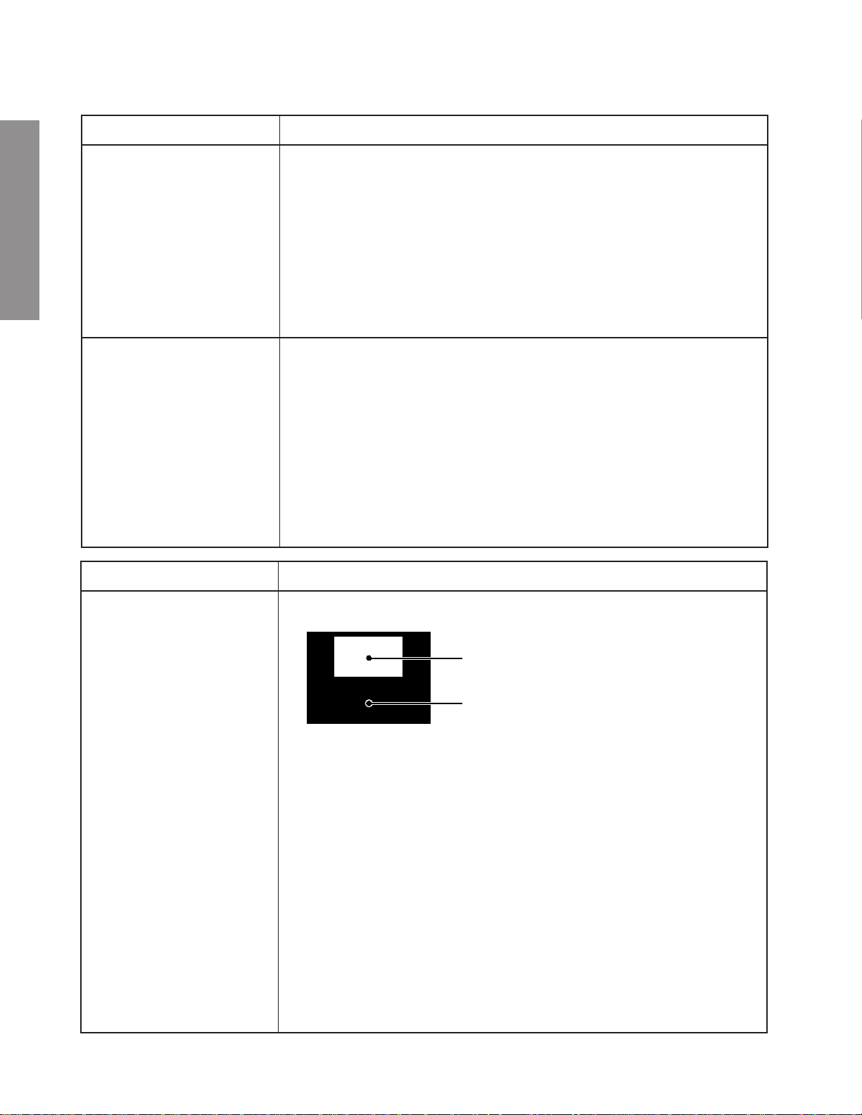
WHITE BALANCE
(RCUT)
(GCUT)
(BCUT)
(RDRV)
(BDRV)
Black and White pattern
High light area
Adjust "RDRV" or "BDRV" to be white.
Low light area
Fine adjust "RCUT", "GCUT" or "BCUT" to be black.
1. Set user control to reset position.
CONTRAST → Max.
(
BRIGHTNESS, COLOR, TINT → Center.
2. Call up the adjustment mode display, then select the item RCUT.
3. Adjust the data of items RCUT, GCUT, and BCUT to "40H".
4. Press the "Info" button on Remote control. (Y-MUTE : ON)
5. Gradually rotate R, G and B screen volume of FOCUS PAC clockwise or
counterclockwise until the raster appears slightly on the CRT through the
each lens, and leave them.
(Lookin to the lens in order to check the raster.)
6. Press the "Info" button on Remote control. (Return to Normal Picture)
7. Press the a button on Remote, and select the Black and White pattern.
8. Adjust the data of items RCUT, GCUT and BCUT for proper white-balanced
picture in low light area.
9. Adjust the data of items RDR V and BDR V for proper white-balanced picture in
high light area.
10. Check the white balance in both low and high light areas.
If necessary, perform again steps from 8 to 9.
)
– 14 –
Page 15

(Reference factory adjustment)
Item Name Setting Input signal Measuring point Adjusting method Adjustment standard
– 15 –
[SCNT]
[BRTC]
[COLP]
[COLS]
[SRY]
[SBY]
Sub-contrast
Sub-bright
center
Sub-color
center
PAL
Sub-color
center
SECAM
SECAM
R-Y black level
SECAN
B-Y black level
Picture mode 1
A
udio system: I
Wide mode
Picture mode 1
Wide mode
Picture mode 1
Wide mode
Picture mode 1
Wide mode
Sub-bright signal
(PAL-I signal)
Sub-bright signal
Sub-bright signal
(PAL)
SECAM color bar
SECAM color bar
SECAM color bar
TP46B SIGNAL unit
Screen adjustment
TP46B
SIGNAL unit
TP46B
SIGNAL unit
TP02
SIGNAL unit
TP01
SIGNAL unit
y Adjust the amplitude from the pedestal
level to the white peak.
y Adjust the number of collapsed black
bars of the sub-bright signal.
x Carry out adjustment after adjusting the
W/B and SCNT.
y Adjust the amplitude of the color bar.
x Adjust the P-P value of the upper half.
y Adjust the amplitude of the color bar.
x Adjust the P-P value of the upper half.
y Adjust so that the level of the mono-
chrome signal part can meet the level of
the H.BLK.
y Adjust so that the level of the mono-
chrome signal part can meet the level of
the H.BLK.
2.4 ± 0.1 Vpp
4 ± 1.5 bars
1.20 ± 0.1 Vpp
1.75 ± 0.1Vop
0 ± 10 mV
0 ± 10 mV
GENERAL ADJUSTMENTS
Page 16

GENERAL ADJUSTMENTS
Item Name Setting Input signal Measuring point Adjusting method Adjustment standard
– 16 –
Screen
adjustment
Focus
adjustment
RDRV
BDRV
RCUT
BCUT
Vert. Center
voltage
adjustment
Screen
Focus
Bright part W/B
Dark part W/B
Center voltage
Factory- screenadjustment mode
Dynamic mode
Cinema mode
Dynamic mode
Wide mode
Retoma signal
(PAL-I)
Crosshatch signal
Phillips pattern
(PAL-I)
CRT screen
Screen adjustment
Screen adjustment
Screen adjustment
Between TP-V and
TP-G
y Make the surrounding as dark as
possible.
x Enter factory-screen-adjustment mode.
(Y mute, DRV.CUT. = 40 H)
c Directly observe the CRT screen, and
adjust the screen VR to the point where
it begins to emit light.
v Use R, G, and B tubes respectively to
perform above-mentioned adjustments.
y Make adjustments to achieve the best
possible position by repeating electrical
and optical focusing.
x Use jigs to protect the CRTs, except the
axis under adjustment, from any light.
c Use R, G, ad B tubes respectively to
perform above-mentioned adjustments.
y Adjust the color temperature of the
bright part (103cd/m
y Adjust the color temperature of the dark
part (17cd/m
2
2
).
).
y Connect a voltmeter and adjust the high
voltage to +30 ± 10mV.
Point where it
begins to emit light.
For details, refer to
the focus adjustment method
8750k–0.002uv
8750k–0.002uv
+30 ± 10mV
Page 17

Focus adjustment method (1/2)
Model Adjustment points Adjustment methods
– 17 –
40WH08G
40WH08B
Electrical focus
Lens focus
(Precautions)
Conditions: (1) RED, BLUE: Internal Retoma signals (PAL)
(2) GREEN: Internal crosshatch signal (white crosshatch on black background)
(3) User adjustment: Dynamic mode, cinema mode
(4) Carry out electrical focus and lens focus after rough adjustment.
(5) Use the jig to protect everything, except the color subjected to adjustment, from exposure to light.
(1)Receive the internal Retoma signals, use the focus VR of the focus pack (Z410), and adjust the electrical focus of
each R and B projection tube to the position where the center of the screen gets optimally focused.
(2)Receive the internal crosshatch signals, use the focus VR of the focus pack (Z410), and adjust the electrical focus of
G so that the vertical scanning lines on the screen center can appear most clearly.
(1)R, B: Receive the internal Retoma signals, watch the screen center and its periphery, and make adjustment to the
best possible focus.
(2)G: Adjust this by the method
y Carry out anticipated adjustment on the G lens, considering the time until the lens focus stabilizes.
x The level of anticipated adjustment on the G lens results in a required level of correction, if an adjustment point is
set on the screen.
c During a heat run, be sure to keep lower the G’s screen VR of the focus pack from turning on the power of the set
until immediately before the cutoff adjustment in order to stabilize the G’s coupling liquid temperature.
GENERAL ADJUSTMENTS
Page 18
– 18 –
GENERAL ADJUSTMENTS
Focus adjustment method (2/2)
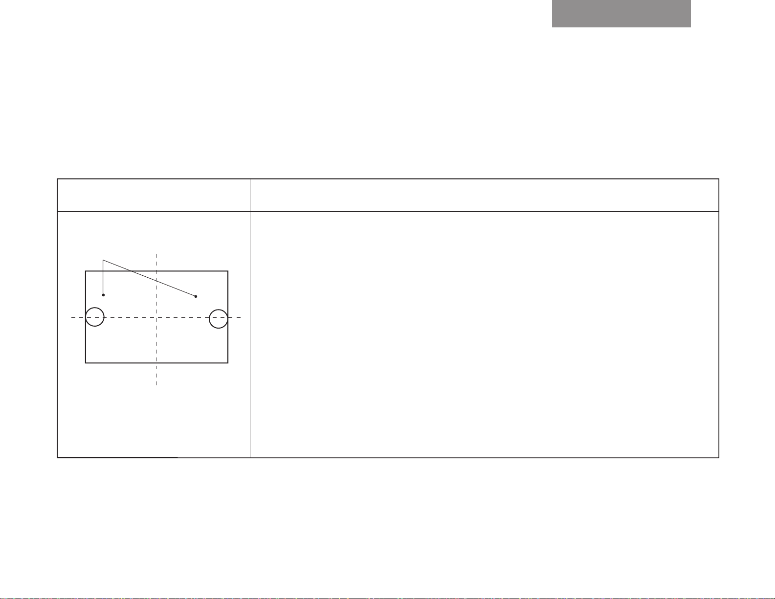
GREEN lens focus adjustment
Model Metodo di regolazione
[1] 40WH08 series (1)Receive internal crosshatch signals, use the lens cap, and concentrate on the single color of G.
(2)Watch the horizon of both the left and right ends on the horizontal axis of the screen, adjust the lens focus of G to
Adjusting points
Left end
Screen
Right end
the very best, and check that the left-and-right focus balance is appropriate.
(Check left-and right balance of G lens focus)
y Use the left (or right) end crosshatch and make the best adjustment on the G’s lens focus.
x Check the right (or left) end focus.
(3)If the left and right lens focus is not properly balanced (tendency for flare), divide and adjust it to the middle grade.
(4)Check on the periphery, and make certain that the focus grade lies within a tolerable level (including flare).
ø 100 mm ø 100 mm
(Point of observation)
Inside the circle of 100mm that is in contact with
left and right bezels.
Page 19

Completion of adjustment
– 19 –
Item Name Setting Input signal Measuring point Adjusting method
Screen
position
adjustment
HIT
VLIN
HIT
HIT
Vertical amplitude adjustment
(PAL WIDE)
Vertical amplitude adjustment
(PAL Super-live)
Vertical amplitude adjustment
(PAL cinema)
Picture mode 1
Picture mode 1
WIDE mode
Picture mode 1
Super-live mode
Picture mode 1
CINEMA mode
Phillips pattern
(PAL-I)
Phillips pattern
(PAL-I)
Phillips pattern
(PAL-I)
Phillips pattern
(PAL-I)
Screen adjustment
Screen adjustment
Screen adjustment
Screen adjustment
(1)Adjust the vertical and horizontal
screen positions and centering magnet
so that the central + mark of the dummy
screen and the + mark of the Phillips
pattern can overlap in conformity.
Carry this out individually on 3 tubes of
R, G, and B
(Note) Do not move HPOS, VPOS data
(1)Turn the screen size to WIDE.
(2)In the first place, shorten the vertical
amplitude using HIT data until the upper
and low flags emerge on the screen.
(3)Then, extend the vertical amplitude with
the HIT data until either upper or lower
flag end conforms to the screen end
(Adjust the vertical center of the pattern
to the central mark of the screen.)
(1)Turn the screen size to Super-live.
(2)Adjust with the HIT so that the top and
bottom of the inner circle of Phillips
pattern will contact the screen edge.
(Note) VLIN adjustment is not performed.
(1)Turn the screen size to CINEMA.
(2)Adjust the registers on the top and
bottom of the Phillips pattern
(Note) Do not touch the centering magnet
Adjustment standard
Less than ø7mm
Upper and lower
flags are to be in
contact
The inner circle is
to contact the
screen edge
GENERAL ADJUSTMENTS
Page 20

Completion of adjustment
GENERAL ADJUSTMENTS
– 20 –
Item Name Setting Input signal Measuring point Adjusting method
HIT
WID
NHIT
NLIN
NHIT
NHIT
NHIT
Vertical amplitude adjustment
(PAL SUBTITLE)
Vertical amplitude adjustment
PAL WIDE
Vertical amplitude adjustment
NTSC WIDE
Vertical amplitude adjustment
SUPER-LIVE
NTSC
Vertical amplitude adjustment
CINEMA
NTSC
Vertical amplitude adjustment
SUB-TITLE
NTSC
Picture mode 1
Super-live mode
Picture mode 1
WIDE mode
Picture mode 1
WIDE mode
Picture mode 1
SUPER-LIVE mode
Picture mode 1
CINEMA mode
Picture mode 1
SUB-TITLE mode
Phillips pattern
(PAL-I)
Phillips pattern
(PAL-I)
Monosco signals
NTSC
LEADERE-435B
Monosco signals
NTSC
LEADER-435B
Monosco signals
NTSC
LEADER-435B
Monosco signals
NTSC
LEADER-435B
Screen adjustment
Screen adjustment
Screen adjustment
Screen adjustment
Screen adjustment
Screen adjustment
(1)Turn the screen size to SUB-TITLE.
(2)Adjust the registers on the top and
bottom of the Phillips pattern as shown
in the next page.
(Note) Do not touch the centering magnet
(1)Turn the screen size to WIDE.
(2)The left and right flags of the Phillips
pattern are to contact the screen edge.
(3)The user center position adjustment is to
be 0.
(1)Turn the screen size to WIDE mode.
(2)The 1st line on the screen is to be
hidden by the mask.
(1)Turn the screen size to SUPER-LIVE
mode.
(2)Adjust so that the upper side 3rd line on
the screen will contact the screen edge.
(3)Do not adjust the NVLI.
(1)Turn the screen size to CINEMA mode.
(2)Adjust so that the character 30 on the
upper, lower, and left-and-right ends will
contact the screen edge.
(1)Turn the screen size to SUB-TITLE
mode.
(2)Adjust so that the upper side 5th line of
the register on the screen will contact the
screen.
(3)The NVLI is not to be adjusted.
Adjustment standard
Page 21

Completion of adjustment
– 21 –
Item Name Setting Input signal Measuring point Adjusting method
NWIDE Horizontal
amplitude
adjustment
WIDE NTSC
Picture mode 1
WIDE mode
Monosco signals
NTSC
LEADER-435B
Screen adjustment (1)Turn the screen size to WIDE.
(2)Adjust the 2nd left register to the left
edge of the screen.
Adjustment standard
GENERAL ADJUSTMENTS
Page 22
1. Screen Adjustment
The four PAL screens Wide/4:3, Super Live, Cinema and Subtitle, and the four NTSC screens Wide/4:3, Super Live,
Cinema and Subtitle are adjusted. When adjusting, input an external signal for matching the sync.
CAUTION: The con vergence circuit eliminates screen distortion but cannot mak e large corrections such as changing
the overall screen size. Use caution because the protection circuit will be activated if corrections are excessively
large. Before starting to adjust the various screens, alwa ys adjust the v ertical size (HIT) and horizontal size (WID) by
changing the main deflection data.
Execute the adjustment screens in the sequence Wide/4:3 → Super Live → Cinema → Subtitle for both PAL and
NTSC.
GENERAL ADJUSTMENTS
1-1. Entering Adjustmet Menu
CONVERGENCE ADJUSTMENT
+ + MENU key
F+7 key
Menu screen
CONVER ADJUST MENU
1
Adjust PAL Wide
2
PAL Wide to Others
3
Adjust PAL S.Live
4
Adjust PAL Cinema
5
Adjust PAL S.title
6
PAL to NTSC (Wide)
7
PAL to NTSC (ALL)
8
Adjust NTSC Wide
9
NTSC Wide to Others
10
Adjust NTSC S.Live
11
Adjust NTSC Cinema
12
Adjust S.title
S
Service data indication
+
or
MENU SELECTION
+ key
SCREEN
ADJUSTMENT
CALL: to exit
Adjusting screen
+ key
– 22 –
Page 23
1-2. Remote Control Key
b
h
i
g
j
n
o
F
1 2 3
4 5 6
7 8 9
INFO.
NexTView
MENU EXIT
SIZE
CALL
TEXT
TV
0
P
ENTER
P
a
o key ...............Push this key twice and the set con-
sole menu key to enter the service
l
b
F key .................Push this key and 7 key to enter
c
k
P
c
Yellow key Convergence adjusting screen key.
g
5 key .................
h
2 key ................. Cursor up / adjusting point up.
i
4 key ................. Cursor left / adjusting point left
j
8 key ................. Cursor down / adjusting point down
k
6 key ................. Cursor right / adjusting point right
l
3 key .................Cursor colour change (Adjusting
m
+ key .................Excutetion key on convergence menu.
n
s key ................ Up key on convergence menu.
o
t key ................ Down key on convergence menu.
mode .
the con vergence menu.
..........
Cursor shift / data change mode
change-over.
colour selection).
GENERAL ADJUSTMENTS
m
VTR / DVD
VTR / DVD
a
Fig. 2
– 23 –
Page 24
1-3. Adjusting Screen
1) Adjusting menu
NO Description
1 Adjust PAL Wide Used for manual adjustment of the Wide/4:3 screen in the PAL mode.
2 P AL Wide to others Automatically sa ves approximate supplementary data f or the other P AL screens based
GENERAL ADJUSTMENTS
3 Adjust PAL S.Live Used for manual adjustment of the PAL Super Live screen.
4 Adjust PAL Cinema Used for manual adjustment of the PAL Cinema screen.
5 Adjust PAL S.title Used for manual adjustment of the PAL S.title screen.
Item
Returns to the original screen data screen before data conversion, explained below.
on the PAL Wide/4:3 screen data.
First, the PAL Wide/4:3 screen data are converted to Super Live and the values are
saved. Next, the data are converted to Cinema and the values are saved. Finally, the
data are converted to Subtitle and the values are sav ed, and then the oper ation ends .
Manually check the other screen modes as described below and make corrections if
distortion, etc., is present.
Please be aware that all PAL screens are re-adjusted when this menu is selected and
executed.
Select this mode for Super Live screen color matching and distortion adjustment.
Use the specified dimensions when adjusting.
Select this mode for Cinema screen color matching and distortion adjustment.
Use the specified dimensions when adjusting.
Select this mode for S.title screen color matching and distortion adjustment.
Use the specified dimensions when adjusting.
6 PAL to NTSC (Wide) PAL Wide/4:3 screen data is calculated, converted to NTSC Wide/4:3 approximate
data and saved.
To assure accurate adjustments, select the manual mode explained below and chec k,
then apply color matching and distortion adjustments.
7 PAL to NTSC (All) Data for all PAL screens is converted to approximate data for the NTSC screens and
saved.
To assure accurate adjustments, select the manual mode explained below and chec k,
then apply color matching and distortion adjustments.
8 Adjust NTSC Wide Used for manual adjustment of the NTSC Wide/4:3 screen.
Select this mode for Wide/4:3 screen color matching and distortion adjustment.
Use the specified dimensions when adjusting.
9 NTSC Wide to others Approximate supplementary data for the other NTSC screens is automatically saved
based on the NTSC Wide/4:3 screen data.
First, the NTSC Wide/4:3 screen data are converted to Super Live and the values are
saved. Next, the data are converted to Cinema and the values are saved. Finally, the
data are converted to Subtitle and the values are sav ed, and then the oper ation ends .
Manually check the other screen modes as described below and make corrections if
distortion, etc., is present.
Please be aware that all NTSC screens are re-adjusted when this menu is selected
and executed.
– 24 –
Page 25
NO Description
Item
10 Adjust NTSC S.Live Used for manual adjustment of the NTSC Super Live screen.
Select this mode for Super Live screen color matching and distortion adjustment.
Use the specified dimensions when adjusting.
11 Adjust NTSC Cinema Used for manual adjustment of the NTSC Cinema screen.
Select this mode for Cinema screen color matching and distortion adjustment.
Use the specified dimensions when adjusting.
12 Adjust NTSC S.title Used for manual adjustment of the NTSC Subtitle screen.
Select this mode for Subtitle screen color matching and distortion adjustment.
Use the specified dimensions when adjusting.
2) Adjustment Screen
X : 1
Y : 1
C : R
S : 08
GENERAL ADJUSTMENTS
Wide
Displayed when the cursor blinks and cleared
when the cursor lights steady.
X Cursor horizontal position display
Displayed when the cursor blinks and
cleared when the cursor lights steady.
Displays the current screen mode.
Y Cursor vertical position display
C Cursor color select display
S Menu select display
3) Adjustment Sequence
When the initial screen opens, X = 1, Y = 1, C = R and S = [Select Menu] are displayed as the defaults. The cursor can
now be moved up, down, left and right using the (2), (8), (4) and (6) keys of the remote control. Select the desired
adjustment and press the (5) key; the cursor will light steady and the screen display will be cleared. Again press the (2),
(8), (4) and (6) keys of the remote control to adjust the shape of the screen. When adjustment has been completed, press
the (+) key to return to the Adjustment Menu. When all of the screen adjustments ha ve been completed, turn off the main
power supply of the set to reset the menu.
– 25 –
Page 26

2. Case Study
In many cases, color matching problems can be solved by returning the HIT and WID data for main deflection to the
initial adjustment values. Convergence cannot be re-adjusted in the following cases.
2-1 When the CRT has been replaced
Main deflection re-adjustment and color matching are necessary when the CRT has been replaced. Use the following
procedure.
1. Replace the blue and red CRTs.
2. Perform the blue and red yoke horizontal adjustments in relation to the green CRT. Press the yokes and speed
modulation coils + alignments onto the CRTs and fasten after making sure that there are no gaps.
3. Adjust the blue and red alignments (refer to the detailed alignment adjustment item).
4. Use centering magnets to center the blue and red CRTs in relation to the green CRT.
5. Adjust the main deflection HIT and WID data, using the most accurate location in relation to the green as data.
6. Use convergence to match the colors for each screen. Green will not work at this time.
GENERAL ADJUSTMENTS
7. When the convergence adjustments have been completed for all screens, then replace the green CRT.
Repeat the procedures in steps 2 - 5 for the green CR T but this time use con vergence to match the colors using red and
blue as reference.
2-2 When replacing the convergence unit
Generally , all of the screens m ust be re-adjusted when the conv ergence unit is replaced, b ut the process can be greatly
shortened by using the following method.
1. Replace the memory (Q711, Q712, Q713) of the new unit with the memory (Q711, Q712, Q713) of the defective unit.
This makes it possible to quickly reproduce the previous screen status when installed in the set.
2. Install the new unit with the old memory in the set and turn on the power . The entire screen will move linearly in either
the vertical or horizontal direction.
3. Use centering magnets to re-adjust the green, red and blue centers.
4. There is possibility of color mismatching or differences in screen siz e when the various screens are check ed. In such
case, adjust the main deflection and apply a slight amount of convergence color matching.
2-3 When none of the above cases apply (rare case)
An unexpected situation or major operational error, etc., could be considered but it is recommended that all screens be
matched starting from the beginning. If the initial positions of the centering magnets are unknown, disconnect the
connectors for the convergence sub-yoke outputs one at a time, adjust the CRT centering and then start the following
adjustments.
1. Make sure that there is plenty of room for the static cross convergence to be moved left, right, up and down. If
sufficient space is not available, move to an appropriate location and then re-adjust the centering.
2. Enter the convergence adjustment mode and call out the menu. (Leave the PAL signal connected.)
3. Select 1. Adjust PAL Wide and adjust the PAL mode Wide/4:3 screen manually in accordance with the dimension
diagram.
4. When the Wide/4:3 screen adjustment has been completed, return to the Main Menu and select 2. PAL Wide to
others.
The screen will change automatically and the Wide, Cinema and Subtitle screens will be created automatically.
5. Next, select 3. Adjust PAL S.Live and mainly adjust in the horizontal direction in accordance with the dimension
diagram.
6. Next, select 4. Adjust PAL Cinema and fine adjust to remove any Cinema screen distortion.
7. Next, select 5. Adjust PAL Subtitle and fine adjust to remove any Subtitle screen distortion.
8. Next, select 7. PAL to NTSC (ALL), then calculate and copy the data for all PAL screens in the NTSC mode. At this
time, the calculations and screen shape changes will be performed automatically and the NTSC screen data
corresponding to the PAL screens will be transferred.
9. Select in sequence 8. Adjust NTSC Wide, 10. Adjust NTSC S.Live, 11. Adjust NTSC Cinema and 12. Adjust NTSC
Subtitle, check the respective NTSC screen modes and, if necessary, adjust for any distortion.
All of the screens can be adjusted with the above process but make every effort not to change the factory data unless
absolutely necessary. Try not to change the convergence data any more than necessary.
– 26 –
Page 27
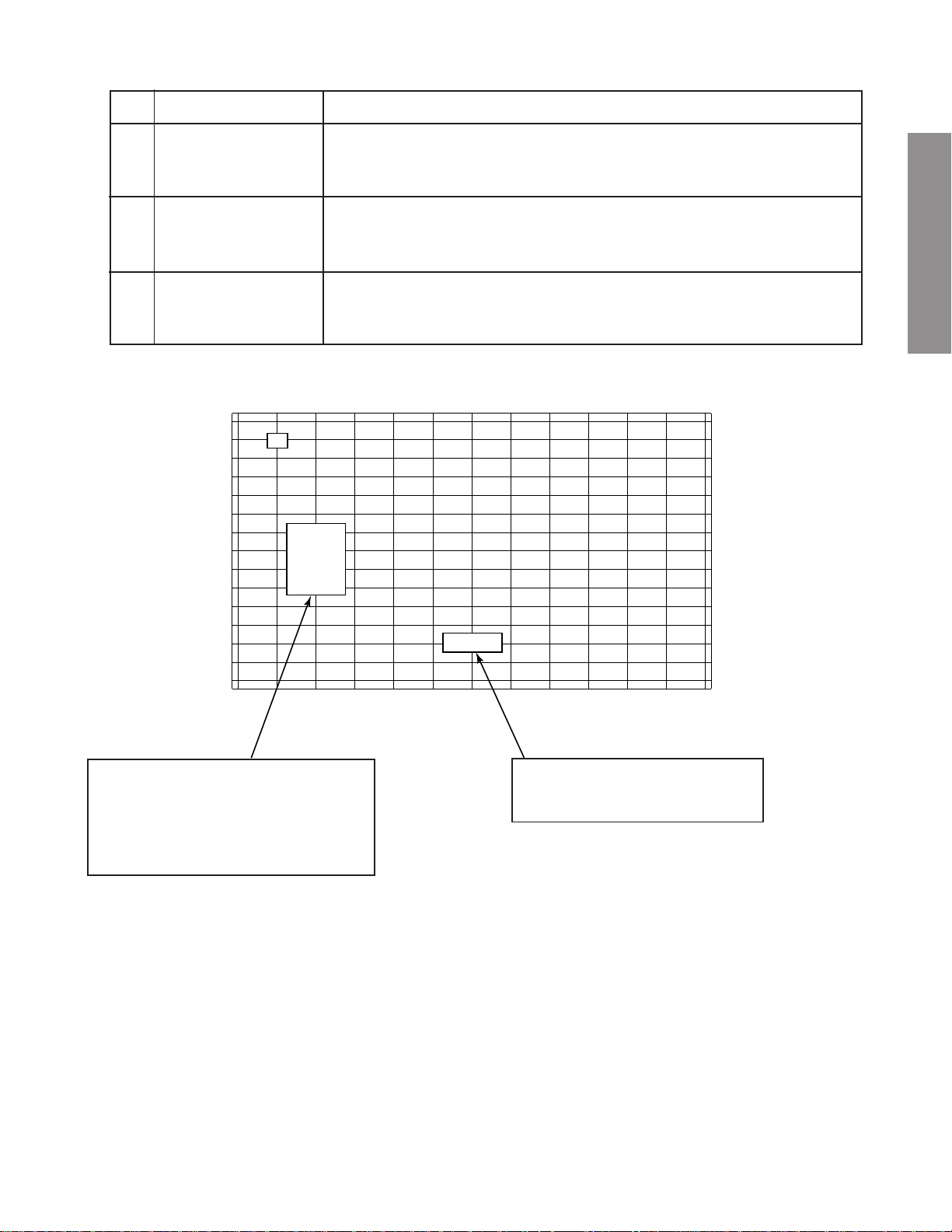
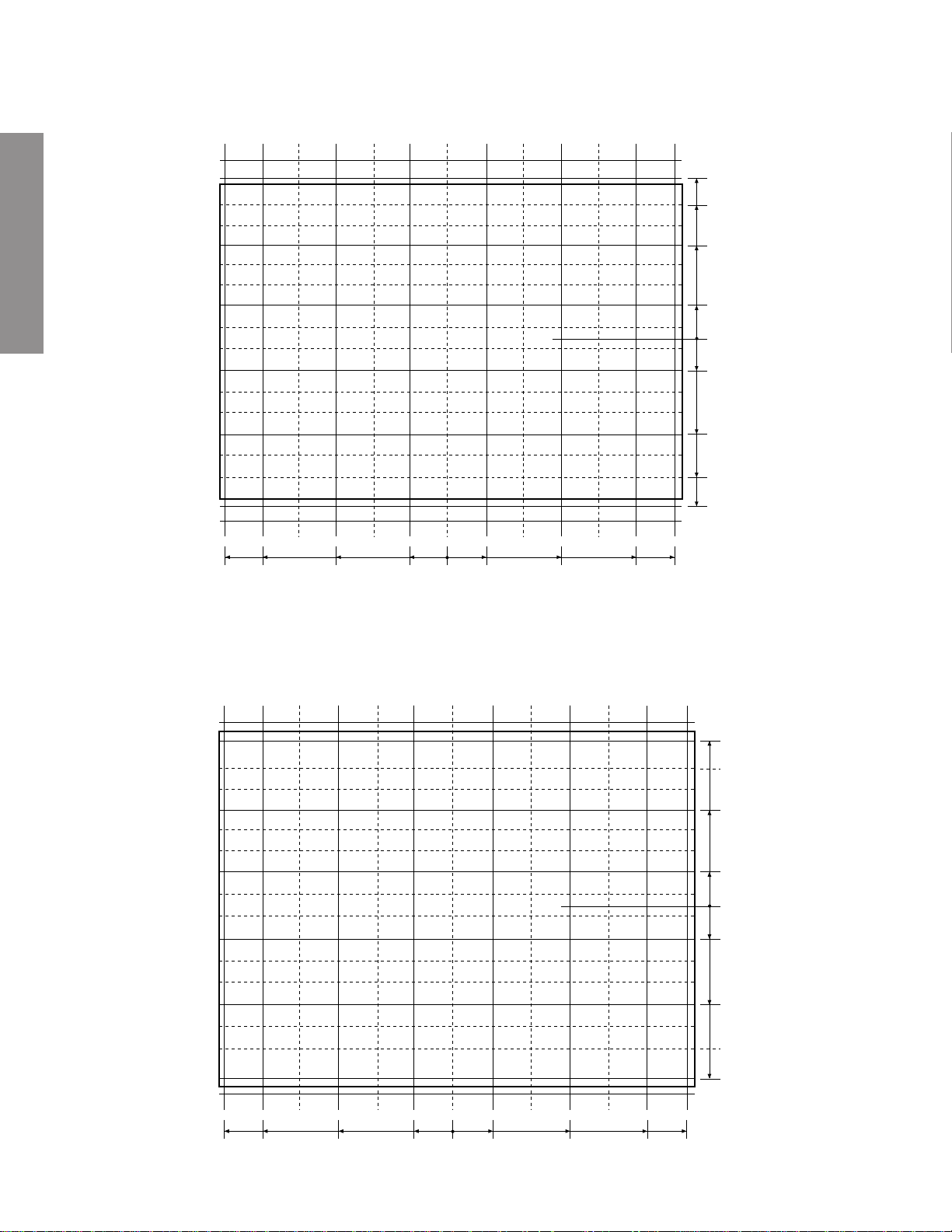
3 Screen adjustment dimensions
3-1 WIDE/4:3 (PAL mode)
380.0
432.5
228.0
76.0
235
207.5
124.5
41.5
0
(screen center)
41.5
124.5
207.5
235
0
76.0
228.0
380.0
432.5
GENERAL ADJUSTMENTS
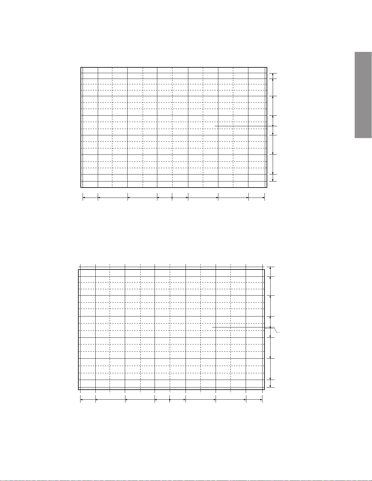
3-2 Super Wide (PAL mode)
428.0
372.0
218.5
72.5
249.0
220.0
130.5
40
0
(pattern center)
-5
49.5
136.5
221.0
249.0
0
72.5
218.5
372.0
428.0
Caution: Do not perform the VLIN adjustment.
– 27 –
Page 28
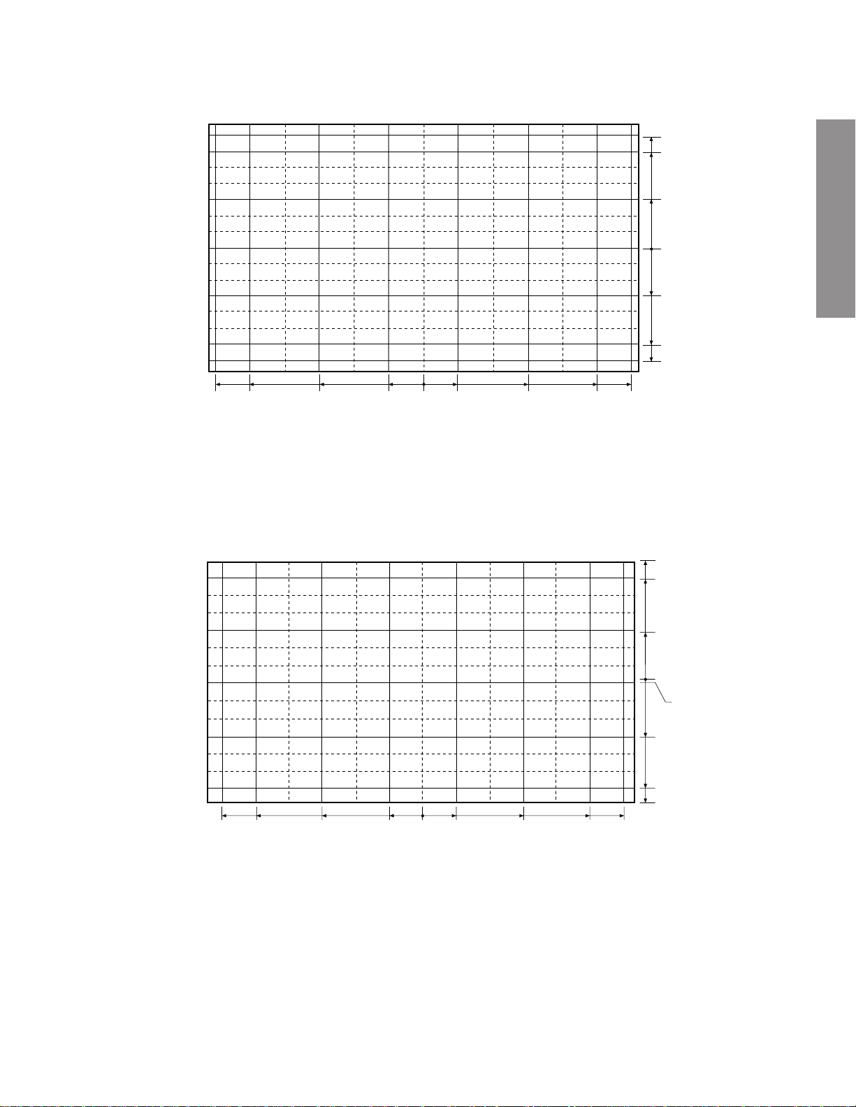
3-3 Cinema (PAL mode)
Note: The cursor will move outside the screen limits in the Cinema mode; therefore, be careful to consider the position
of the cursor displayed on the screen when making adjustments.
262.5
227.5
157.5
52.5
GENERAL ADJUSTMENTS
3-4 Subtitle (PAL mode)
Note: The cursor will move outside the screen limits in the Subtitle mode; therefore, be careful to consider the position
of the cursor displayed on the screen when making adjustments.
Note: Please be aware that the Subtitle screen con vergence pattern center is located at the center of the screen b ut the
image center is located approximately 13mm above that.
432.5
380.0
228.0
76.0
0
52.5
157.5
227.5
262.5
0
76.0
228.0
380.0
432.5
272
240
Screen limit changed
432.5
380.0
228.0
76.0
0
– 28 –
76.0
228.0
380.0
144
48
0
48
144
240
272
432.5
Page 29
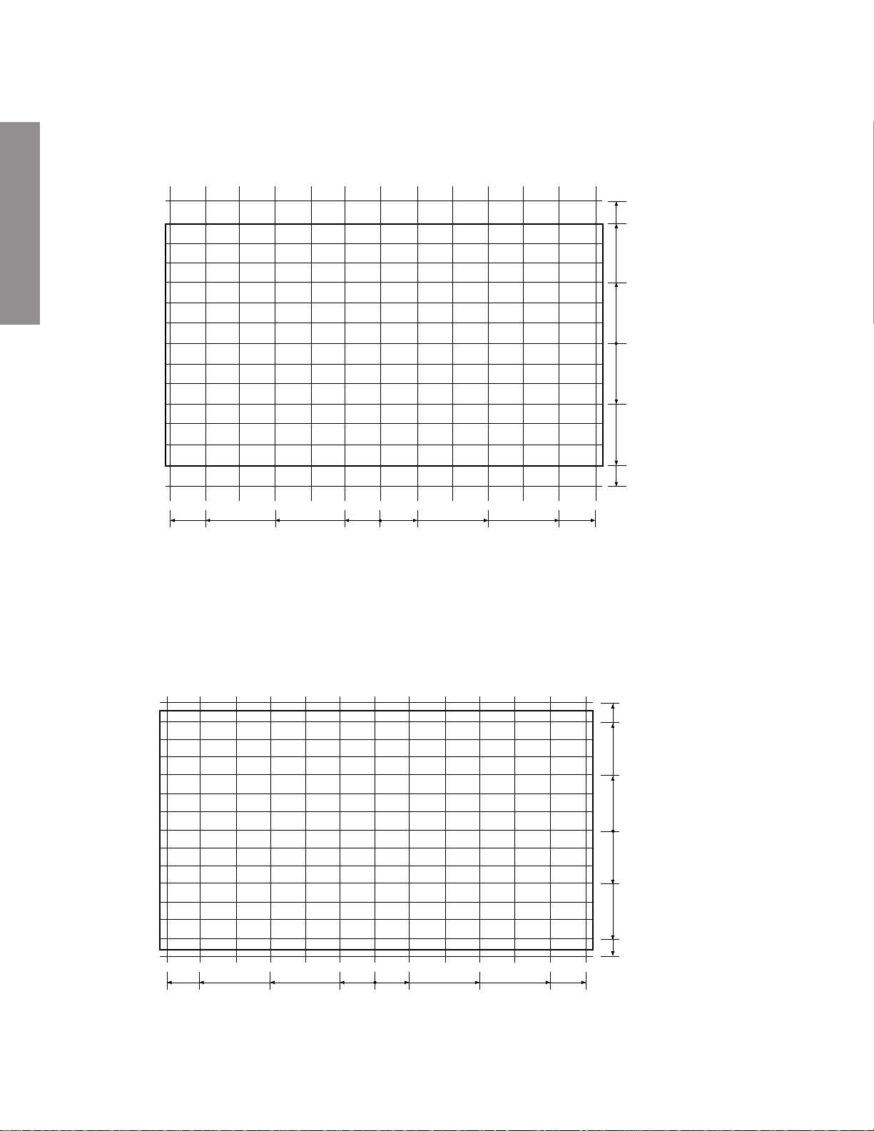
3-5 WIDE/4:3 (NTSC mode)
231
198
99
(screen center)
0
432.5
380.0
3-6 Super Live (NTSC mode)
228.0
76.0
99
198
231
0
76.0
228.0
380.0
432.5
249
213
105
0
(pattern center)
-5
GENERAL ADJUSTMENTS
0
428.0
372.0
218.5
72.5
Caution: Do not perform the VLIN adjustment.
– 29 –
72.5
218.5
372.0
112
216
249
428.0
Page 30
3-7 Cinema (NTSC mode)
Note: The cursor will move outside the screen limits in the Cinema mode; therefore, be careful to consider the position
of the cursor displayed on the screen when making adjustments.
Note: Please be aware that the Cinema screen convergence pattern center is located at the center of the screen but
the image center is located approximately 13mm above that.
GENERAL ADJUSTMENTS
287
246
123
0
123
246
287
0
432.5
380.0
228.0
76.0
76.0
228.0
380.0
432.5
3-8 Subtitle (NTSC mode)
Note: The cursor will move outside the screen limits in the Subtitle mode; therefore, be careful to consider the position
of the cursor displayed on the screen when making adjustments.
Note: Please be aware that the Subtitle screen convergence pattern center is located at the center of the screen but
the image center is located approximately 32mm above that.
266
228
114
0
114
228
266
432.5
380.0
228.0
76.0
0
76.0
228.0
380.0
432.5
– 30 –
Page 31

SCREEN AND MIRROR ALIGNMENTS
ASSEMBLING AND MOUNTING OF
FRONT SCREEN
* Please refer to MECHANICAL DISASSEMBLY page 37.
CLEANING OF LENS AND MIRROR
CAUTION : Do not hold the optical system parts (lens and
mirror) with bare hand to avoid finger-prints on
the surface of those parts.
GENERAL ADJUSTMENTS
HOW TO CLEAN LENS AND MIRROR
1. Be sure to remove sand dust with an air brush, etc.
2. When it is stained slightly, breathe upon it and wipe away
with the specified cleaning cloth.
For other stains than the above, wipe the stains away with
the specified cloth into which a cleaning liquid has been
soaked.
Cleaning liquid ................... LENS LUSTER (Manufactured
by Edmund Scientific Co.), etc.
HOW TO CLEAN SCREEN
When cleaning the screen, use a soft cloth so as not to damage the screen.
1. Wipe the stain away with a diluted neutral detergent soaked
cloth.
2. Wipe the detergent away with a water soaked cloth.
3. Wipe the screen with a dry cloth to remove moisture on the
screen.
Note : Absolutely do not use alcohol, benzine, thinner, etc.
for cleaning in order not to wipe away the black print
on the surface.
– 31 –
Page 32

HIGH VOLTAGE CHECK
CAUTION: There is no HIGH VOLTAGE ADJUSTMENT on this chassis. Checking should be done following the steps below.
1. Connect an accurate high voltage meter to the anode of the picture tube.
2. Turn on the receiver. Set the BRIGHTNESS and CONTRAST to minimum (zero beam current).
3. High voltage must be measured below (B) kV.
Refer to table-1 for high voltage (B).
(See SETTING & ADJUSTING DATA on page 33)
4. Vary the BRIGHTNESS to both extremes to be sure the high voltage does not exceed the limit under any conditions.
CAUTION:
When the following parts fail, check the High Voltage after replacing.
GENERAL ADJUSTMENTS
CIRCUIT CHECKS
Location
No.
T461
D489
Q480
Q483
R435
R489
R490
R450
C440
C443
C444
ANODE VOLTAGE MEASURING METHOD
CAUTION: Take extra precaution when measuring this high voltage. High voltages are also present in surrounding circuit
boards (CRT DRIVE assembly, DEFLECTION assembly, and POWER SUPPLY assembly).
1. Disconnect the FBT anode cable as outlined below. Measure high voltage at the point where the cable enters the FBT.
2. Holding the rubber cover firmly, turn it counterclockwise and check that the lock has been disengaged. (See Fig. b on page
8.)
3. Determine the extent of the rubber cover before disconnecting the cable.
4. Pull straight up the anode cable to disconnect.
5. When reconnecting the cable, proceed in the reverse order.
After reconnecting, tug on the cable to check that it is secure.
Name
Flyback Trans.
Zener Diode
Transistor
IC
Resistor
Resistor
Resistor
VR
Capacitor
Capacitor
Capacitor
Name
TFB3078BD
MTZJ3.6B
2SC2023
TA7508P(J)
33k ohm, ±5%
3.3k ohm, ±5%
3.3k ohm, ±5%
1k ohm
1000pF, ±3%
6800pF, ±3%
5100pF, ±3%
– 32 –
Page 33

CHAPTER 2 SPECIFIC INFORMATIONS
SETTING & ADJUSTING DATA
SAFETY INSTRUCTIONS
HIGH VOLTAGE AT ZERO BEAM:
MAX HIGH VOLTAGE:
AV VOLTAGE
Table-1
SERVICE MODE
(A)
(B)
(C)
40"
32.3 kV
33.8 kV
230 V
ADJUSTING ITEMS AND DATAS IN THE SERVICE MODE:
Item
RCUT
GCUT
BCUT
RDRV
BDRV
BRTC
COLP
COLS
SCNT
SRY
SBY
HPOS
* This data is not a service item of WH08. (described references data for wide)
R CUTOFF (B/W)
G CUTOFF (B/W)
B CUTOFF (B/W)
R DRIVE
B DRIVE
SUB BRIGHT CEN
SUB COLOR CEN PAL
SUB COLOR CEN SECAM
SUB CONTRAST
SECAM R-Y
SECAM B-Y
50Hz H-POSITION
Adjustment
*
ITEM
HIT
VLIN
Reference data
67H (WIDE)
WIDE
3FH
11H
40H
40H
40H
40H
40H
80H
3DH
3DH
08H
07H
01H
Reference data by Picture Size
4:3
3FH
11H
(PAL WIDE)
Item
VPOS
HIT
VLIN
VSC
VPS
WID
P
ARA
CNR
TRAP
VFCV-F CORRECTION* 0FH (WIDE)
VCEN
Table-2
SuperLive
4CH
0EH
Table-2-1
-POSITION*
V
HEIGHT (Table 2-1)
V-LINEARITY (Table 2-1)
V-S CORRECTION*
V-SHIFT*
PICTURE WIDTH
E-W PARABOLA*
E-W CORNER*
TRAPEZIUM*
-CENTER
V
Cinema
62H
11H
Adjustment
Substitle
51H
11H
14:9
51H
11H
Reference data
09H (WIDE)
3FH (WIDE)
11H (WIDE)
0BH (WIDE)
1CH (WIDE)
1EH (WIDE)
11H (WIDE)
01H (WIDE)
20H (WIDE)
6AH (WIDE)
SPECIFIC INFORMATIONS
DESIGN MODE
ADJUSTING ITEMS AND DATAS IN THE DESIGN MODE:
Item Name of adjustment
OPT1
OPT0
OPTION 1
OPTION 0
Preset Data of Preset Data of
40WH08G 40WH08B
7EH 7EH
B0H 91H
Remarks
Table-3
– 33 –
Page 34

Front
LOCATION OF CONTROLS
SPECIFIC INFORMATIONS
Back
EXTERNAL SPEAKER
SWITCH
EXTERNAL SPEAKER
TERMINAL
HEAD PHONE
(VIDEO-3) S-VIDEO TERMINAL
VIDEO-3
MENU
VOLUME DOWN
VOLUME UP
POSITION DOWN
DIGITAL AUDIO INPUT (COAXIAL)
DIGITAL AUDIO INPUT (OPTICAL)
MAIN SWITCH
POWER (RED)
ON TIMER (GREEN)
BILINGUAL (ORANGE)
STEREO (GREEN)
EXIT
POSITION UP
WOOFER SWITCH
WOOFER OUT
VIDEO-1 (21PINS FULL)
VIDEO-2 (21PINS S-VIDEO/AV)
AERIAL TERMINAL
AUDIO OUT (FIXED)
VIDEO-4 (COMP. VIDEO IN)
VIDEO-3 (21PINS S-VIDEO/AV)
– 34 –
Page 35

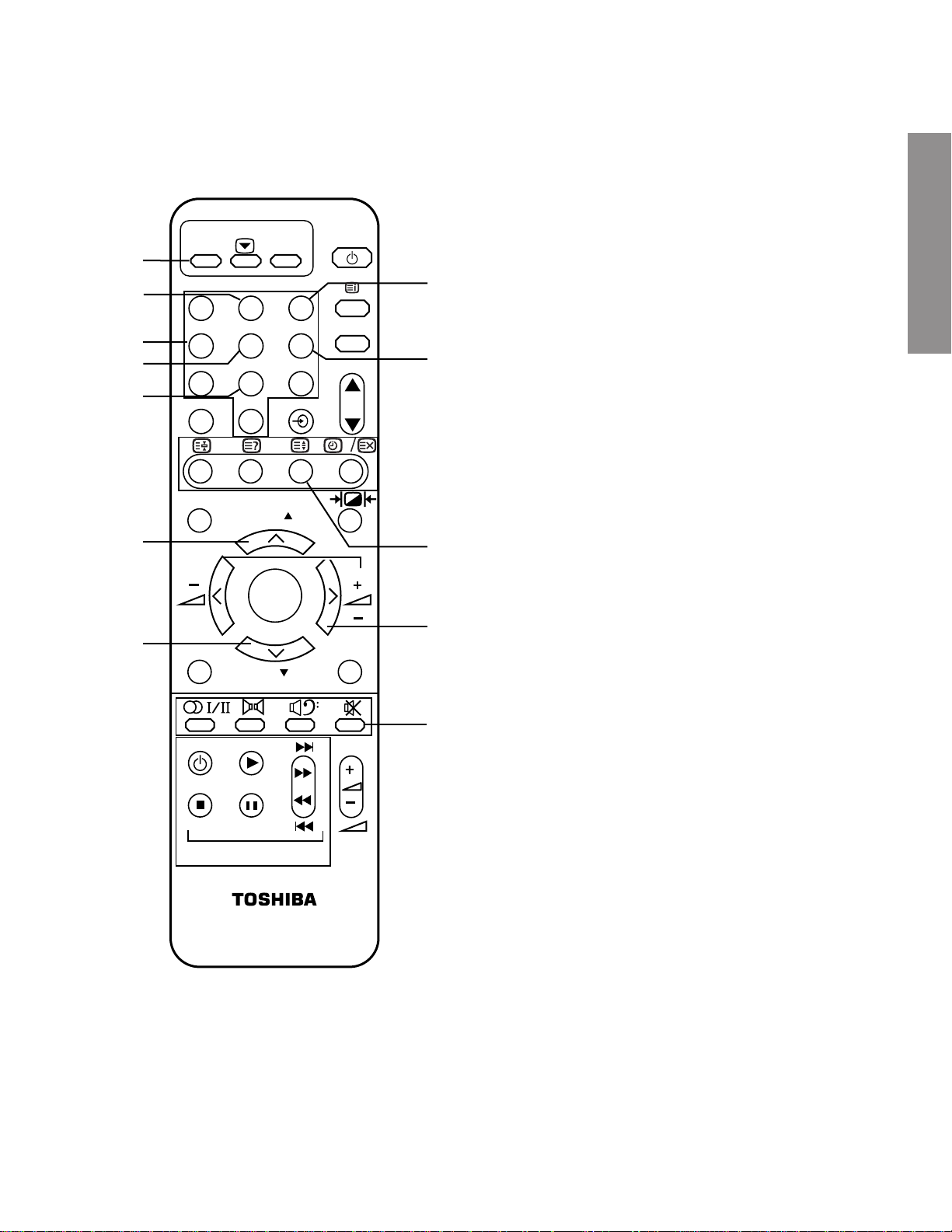
Remote Controller
SIZE Button
Keypad Number Buttons
INFO Buttons
Teletext
NexTView Buttons
Menu Control Buttons
MENU Buttons
F
F
1 2 3
4 5 6
SIZE
CALL
TEXT
TV
Power ON/ OFF
CALL
Teletext
7 8 9
INFO.
0
P
•Programme Position up/down
VIDEO
NexTView
P
Picture Controls
SPECIFIC INFORMATIONS
Menu Control Buttons
ENTER
MENU EXIT
P
ENTER
EXIT
Video Recoder/DVD Buttons
to operate your Toshiba
Video Recorder & DVD
VTR / DVD
VTR / DVD
•Stereo/Bilingual
•Sound Mute
Volume
– 35 –
Page 36

Rear
INT SPEAKEREXT SPEAKER
CRT .RCRT . GCRT.B
VIDEO OUT
VIDEO OUT
VIDEO OUT
SVM OUT
Q761,Q771
Q901,Q902
SVM OUT
Q711,Q712
Q911,Q912
SVM OUT
Q784,Q785
Q921,Q922
V OUT
Q301
H OUT
Q401
C
CONVER OUT
Q751,Q752
DY
DY
DY
SVMSVMSVM
D CONVER
RGBYs
Rear AMP
Q641
Center AMP
Q621
Main AMP
Q610
RGB PROCESSOR
Q510
RGB
SVM
OSD
QR01
RGB
RGB
MIXER
SCAN PROCESSOR
Q4420
E/W
CORRECTION
VP
DPC OUT
H
UP CONVERTER
VD
BLK/CP/B-MASK
YCbCr->YUV
Y2/U/Vin
TEXT
RGBYs
Q460
Q302
FBT
AFC
AMP
Y
U
V
ADC
MPX
ADC
TC90A61F
DFS
VD
PLL
PLL
HD
HD
EM636327Q
SGRAM
TIF
MAA
H001
H002
L,R,SL,SR,C
L,R
C
SL,SR
W
L,R OUT-1
TV-L,R
TV-V
ANT
DIGITAL
AUDIO IN
W-OUT
AMP
W
AV SWQV01
E1
E2
E3
I/O1
I/O2
I/O3
#8
#8
#8
TV-L,R out
V,L,R OUT-2
AUDIO OU T
FIX
RGBYs
Y/V,C,L,R
S1
V1
V,L,R
S2
FRONT
S+AV
MICRO
PROCESSOR
QA01
EEP-ROM
QA02
CLK,DATA,CS,BUSY,RST
SGV
SDA3,SCL3
SDA,SCL
SYNC-AV
SYNC-OUT
RGB
MULTI COLOR DECODER
Q501
EPG SW
CVBSout
Y1 in
Yviout
SYNCin
YCbCr
HD/VD
RGB1in
E4(YCbCr)
YCbCr1in
CVBS/Y2in
C-OUT
C1in
D-COMB
Y-OUT
CVBS/Y1in
COMBin
QZ01
5V-1
D801
Q810
REG
D802
Q801
STR-Z4369
AUDIO31V
+B(120V)
+15V
-15V
11V
7V
T862
D856
D860
D855
D854
D859
PROTECTOR
Z801
REG
REG
REG
REG
REG
9V
9V
5V
5V
5V
Q830
Q831
Q832
Q833
Q834
D820
STR-F6668
Q823
T864
AUDIO26V
D832
MIP0224SY
Q825
T865
32V
EPG-5V
SI F
Q631
S631
W
S601
Y/V,C,L,R
SPECIFIC INFORMATIONS
CIRCUIT BLOCK DIAGRAM
– 36 –
Page 37

K502
MECHANICAL DISASSEMBLY
K501
LABELS
16 SCREWS
8 SCREWS
A201
A264
10 SCREWS
8 SCREWS
A262
K601
A262
SCREWS
A420
A424
SPECIFIC INFORMATIONS
A103
K101
K102
K103
A213 (A214)
(A223)
A202
A268
A102
6 SCREWS
A101
– 37 –
Page 38

CHASSIS AND CABINET REPLACEMENT PARTS LIST
WARNING: BEFORE SERVICING THIS CHASSIS, READ THE “X-RAY RADIATION PRECAUTION”, “SAFETY
PRECAUTION” AND “PRODUCT SAFETY NOTICE” ON PAGE 3 OF THIS MANUAL.
CAUTION: The international hazard symbols “ ” in the schematic diagram and the parts list designate com-
ponents which have special characteristics important for safety and should be replaced only with types identical to
those in the original circuit or specified in the parts list. The mounting position of replacements is to be identical with
originals. Before replacing any of these components, read carefully the PRODUCT SAFETY NOTICE. Do not
degrade the safety of the receiver through improper servicing.
NOTICE:
•
The part number must be used when ordering parts, in order to assist in processing, be sure to include the Model
number and Description.
•
The PC board assembly with * mark is no longer available after the end of the production.
ABBREVIATIONS:
Capacitors ............. CD : Ceramic Disk PF : Plastic Film EL : Electrolytic
Resistors ............... CF : Carbon Film CC : Carbon Composition MF : Metal Film
OMF : Oxide Metal Film VR : Variable Resistor FR : Fusible Resistor
(All CD and PF capacitors are ±5%, 50V and all resistors, ±5%, 1/6W unless otherwise noted.)
Models :40WH08G, 40WH08B
Location
No.
CAPACITORSCAPACITORS
CAPACITORS
CAPACITORSCAPACITORS
C102 24763221 EL, 220?F, ±20%, 16V
C105 24212102 CD, 1000pF, ±10%
C106 24797100 EL, 10?F, ±20%, 50V
SPECIFIC INFORMATIONS
C108 24763221 EL, 220?F, ±20%, 16V
C109 24232103 CD, 0.01?F, +80%, -20%
C110 24797479 EL, 4.7?F, ±20%, 50V
C111 24797220 EL, 22?F, ±20%, 50V
C115 24232103 CD, 0.01?F, +80%, -20%
C201 24567104 PF, 0.1?F
C202 24232103 CD, 0.01?F, +80%, -20%
C203 24567104 PF, 0.1?F
C204 24669010 EL, 1?F, ±20%, 50V
C205 24669229 EL, 2.2?F, ±20%, 50V
C206 24206220 EL, 22?F, ±20%, 50V
C212 24794100 EL, 10?F, ±20%, 16V
C214 24567334 PF, 0.33?F
C215 24436101 CD, 100pF
C219 24436100 CD, 10pF, ±0.25pF
C220 24436100 CD, 10pF, ±0.25pF
C221 24436100 CD, 10pF, ±0.25pF
C229 24092398 CD, 0.1?F, +80%, -20%, 25V
C230 24232103 CD, 0.01?F, +80%, -20%
C232 24092398 CD, 0.1?F, +80%, -20%, 25V
C261 24669101 EL, 100?F, ±20%, 50V
C262 24232103 CD, 0.01?F, +80%, -20%
C263 24794470 EL, 47?F, ±20%, 16V
C264 24794100 EL, 10?F, ±20%, 16V
C301 24567683 PF, 0.068?F
C302 24567224 PF, 0.22?F
C304 24567104 PF, 0.1?F
C305 24567103 PF, 0.01?F
C306 24591102 PF, 1000pF
C307 24617915 EL, 1?F, ±10%, 50V
C308 24591203 PF, 0.02?F
C309 24591102 PF, 1000pF
C310 24669101 EL, 100?F, ±20%, 50V
C311 24567103 PF, 0.01?F
C312 24591102 PF, 1000pF
C313 24666101 EL, 100?F, ±20%, 16V
C314 24567104 PF, 0.1?F
Part No. Description
Location
No.
C315 24666102 EL, 1000?F, ±20%, 16V
C315 24797478 EL, 0.47?F, ±20%, 50V
C316 24666101 EL, 100?F, ±20%, 16V
C317 24591222 PF, 2200pF
C318 24591182 PF, 0.0018?F
C319 24667101 EL, 100?F, ±20%, 25V
C320 24669101 EL, 100?F, ±20%, 50V
C321 24669101 EL, 100?F, ±20%, 50V
C322 24567393 PF, 0.039?F
C323 24567563 PF, 0.056?F
C324 24669101 EL, 100?F, ±20%, 50V
C325 24082057 PF, 0.22?F, 100V
C326 24567224 PF, 0.22?F
C327 24666101 EL, 100?F, ±20%, 16V
C328 24082260 PF, 4700pF, 100V
C329 24669100 EL, 10?F, ±20%, 50V
C330 24085946 EL, 10?F, ±20%, 16V,
C331 24567103 PF, 0.01?F
C332 24669221 EL, 220?F, ±20%, 50V
C333 24693473 PF, 0.047?F, 100V
C334 24212471 CD, 470pF, ±10%
C335 24567104 PF, 0.1?F
C350 24567474 PF, 0.47?F
C351 24567104 PF, 0.1?F
C370 24669229 EL, 2.2?F, ±20%, 50V
C371 24591623 PF, 0.056?F
C372 24212101 CD, 100pF, ±10%
C401 24214332 CD, 3300pF, ±10%, 500V
C401 24232103 CD, 0.01?F, +80%, -20%
C402 24214391 CD, 390pF, ±10%, 500V
C403 24567223 PF, 0.022?F
C404 24797229 EL, 2.2?F, ±20%, 50V
C405 24567124 PF, 0.12?F
C412 24829823 PF, 0.082?F, 400V
C415 24092478 CD, 470pF, ±10%, 2kV
C416 24676220 EL, 22?F, ±20%, 100V
C417 24095716 PF, 1.5?F, ±10%, 250V
C423 24095786 PF, 0.33?F, 400V
C424 24763101 EL, 100?F, ±20%, 16V
C425 24095787 PF, 0.3?F, 400V
Part No. Description
Non-Polar
– 38 –
Page 39

TERMINAL VIEW OF TRANSISTORS
1 2SD2253
(old)
2SC5243
B
C
E
6 RN2203
RN2201
RN2004
RN1203
SPECIFIC INFORMATIONS
RN1204
RN2204
RN1205
RN1202
RN1201
B
C
E
2 2SC3852
2SD1763A
2SC1569
2SC4544
2SA1788
2SA1306
2SA1186A
B
C
E
7 2SD1554
2SD2253
2SD1556
2SC5143
2SD2553
2SC5144
B
C
E
3 2SC752GTM
2SC2482
2SC2655
2SC4721P
E
C
B
8 ON4409
B
C
E
4 2SC752
2SA562TM
2SA1015
2SC1815
2SC2878
2SC1740S
2SC2120
2SA9335
E
C
B
5 2SA1788
B
C
E
– 80 –
Page 40

FILE NO. 033-200205
SERVICE MANUAL
COLOUR TELEVISION
C00S Chassis
32ZP18Q
– SUMMARY –
32ZP18Q is the same as 32ZP18P except for the parts tabled on back of this sheet.
Use this service manual together with the original service manual of
No. 030-200105).
36ZP18P, 32ZP18P
(File
PUBLISHED IN JAPAN, Feb., 2002 So
Page 41

REPLACEMENT PARTS LIST DIFFERENCES
Location
No.
CT01 24792221 EL, 220?F, ±20%, 6.3V
CT02 24109103 Chip, 0.01?F, ±10%
CT03 24109103 Chip, 0.01?F, ±10%
CT04 24793101 EL, 100?F, ±20%, 10V
CT05 24100104 Chip, 0.1?F, +80%, -20%, 25V
CT06 24793470 EL, 47?F, ±20%, 10V
CT07 24092538 Chip, 1?F, +80%, -20%, 10V
CT08 24105560 Chip, 56pF
CT09 24105560 Chip, 56pF
CT10 24793470 EL, 47?F, ±20%, 10V
CT11 24100104 Chip, 0.1?F, +80%, -20%, 25V
CT12 24793470 EL, 47?F, ±20%, 10V
CT13 24100104 Chip, 0.1?F, +80%, -20%, 25V
CT14 24100104 Chip, 0.1?F, +80%, -20%, 25V
CT17 24100104 Chip, 0.1?F, +80%, -20%, 25V
CT19 24794100 EL, 10?F, ±20%, 16V
CT20 24109103 Chip, 0.01?F, ±10%
CT21 24794100 EL, 10?F, ±20%, 16V
CT23 24100104 Chip, 0.1?F, +80%, -20%, 25V
CX111 24092621 Chip, 1?F, ±10%, 10V
CX121 24774470 Chip, 47pF, CH
CX130 24092293 Chip, 0.1?F, +80%, -20%, 25V
CX241 24092293 Chip, 0.1?F, +80%, -20%, 25V
CX243 24092293 Chip, 0.1?F, +80%, -20%, 25V
CX244 24092293 Chip, 0.1?F, +80%, -20%, 25V
CX245 24092293 Chip, 0.1?F, +80%, -20%, 25V
CX246 24092293 Chip, 0.1?F, +80%, -20%, 25V
CX247 24872331 Chip, 330 ohm, 1/16W
CX249 24092293 Chip, 0.1?F, +80%, -20%, 25V
CX250 24092293 Chip, 0.1?F, +80%, -20%, 25V
GT03 24011472 Chip, 4700 ohm, 1/20W
GT04 24011472 Chip, 4700 ohm, 1/20W
GT05 24011472 Chip, 4700 ohm, 1/20W
GT07 24000445 Chip Jumper, 1680 Type
GT09 24011103 Chip, 10k ohm, 1/20W
K902 23306435 Remote Hand Unit, CT-90101
LT01 23103828 Chip (Ferrite Bead), TEM2121M
LT02 23103828 Chip (Ferrite Bead), TEM2121M
LT03 23103828 Chip (Ferrite Bead), TEM2121M
LT04 23103828 Chip (Ferrite Bead), TEM2121M
LT05 23103828 Chip (Ferrite Bead), TEM2121M
LT07 23103828 Chip (Ferrite Bead), TEM2121M
LT08 23103828 Chip (Ferrite Bead), TEM2121M
LT09 23103828 Chip (Ferrite Bead), TEM2121M
LT11 23103828 Chip (Ferrite Bead), TEM2121M
LT12 23103828 Chip (Ferrite Bead), TEM2121M
LX241 23103822 Chip (Ferrite Bead), TEM2117T
QA01 23009082 IC, 750010-179S
QR01 23009037 IC, MB90096P-232
QR03 23205123 Transistor, 2SA933ASQ
QT01 23000724 IC, SAA5665/0531
QT02 23314993 Transistor, 2SC4081T106Q
QT03 70114402 Transistor, 2SC3437Y-L
QT05 23314993 Transistor, 2SC4081T106Q
QT06 23000283 IC, R1121N331B-T
QT08 23314993 Transistor, 2SC4081T106Q
QT09 23000727 IC, M51008BVP12V
QT10 23314993 Transistor, 2SC4081T106Q
QT11 23009114 IC, BD4746G-TR
QT12 23314994 Transistor, 2SA1576AT106
QT13 23314994 Transistor, 2SA1576AT106
QT14 23314994 Transistor, 2SA1576AT106
QT15 23314994 Transistor, 2SA1576AT106
Part No. Description
Location
No.
QX02 23000198 IC, EM636327Q-8
QX21 23318824 IC, TC7S08F T85L
RT01 24011101 Chip, 100 ohm, 1/20W
RT02 24011101 Chip, 100 ohm, 1/20W
RT03 24011102 Chip, 1k ohm, 1/20W
RT04 24011102 Chip, 1k ohm, 1/20W
RT05 24011100 Chip, 10 ohm, 1/20W
RT06 24011332 Chip, 3300 ohm, 1/20W
RT07 24011473 Chip, 47k ohm, 1/20W
RT08 24011473 Chip, 47k ohm, 1/20W
RT09 24011332 Chip, 3300 ohm, 1/20W
RT10 24011222 Chip, 2200 ohm, 1/20W
RT11 24011332 Chip, 3300 ohm, 1/20W
RT12 24011222 Chip, 2200 ohm, 1/20W
RT13 24011102 Chip, 1k ohm, 1/20W
RT14 24011102 Chip, 1k ohm, 1/20W
RT15 24011473 Chip, 47k ohm, 1/20W
RT16 24011473 Chip, 47k ohm, 1/20W
RT18 24011223 Chip, 22k ohm, 1/20W
RT19 24000445 Chip Jumper, 1680 Type
RT20 24011102 Chip, 1k ohm, 1/20W
RT21 24011332 Chip, 3300 ohm, 1/20W
RT22 24011222 Chip, 2200 ohm, 1/20W
RT23 24000445 Chip Jumper, 1680 Type
RT24 24000594 Chip, 12k ohm, ±1%, 1/16W
RT26 24011472 Chip, 4700 ohm, 1/20W
RT27 24000594 RM73B1J123FD
RT28 24011101 Chip, 100 ohm, 1/20W
RT29 24011101 Chip, 100 ohm, 1/20W
RT30 24011473 Chip, 47k ohm, 1/20W
RT31 24011103 Chip, 10k ohm, 1/20W
RT32 24011103 Chip, 10k ohm, 1/20W
RT33 24011472 Chip, 4700 ohm, 1/20W
RT34 24011222 Chip, 2200 ohm, 1/20W
RT35 24011102 Chip, 1k ohm, 1/20W
RT37 24011101 Chip, 100 ohm, 1/20W
RT38 24011151 Chip, 150 ohm, 1/20W
RT39 24011561 Chip, 560 ohm, 1/20W
RT40 24011151 Chip, 150 ohm, 1/20W
RT42 24011470 Chip, 47 ohm, 1/20W
RT43 24011151 Chip, 150 ohm, 1/20W
RT44 24011103 Chip, 10k ohm, 1/20W
RX107 24872821 Chip, 820 ohm, 1/16W
RX130 24872561 Chip, 560 ohm, 1/16W
RX131 24782102 Chip, 1k ohm, 1/16W
U104 23787220 TEXT Board, PD0267B
*
U105 23784880 DFS SDRAM Board, PB9512A
*
U902A 23787222 SIGNAL/BLA Board, PD0039C
*
XT01 23153930 Crystal, 12.0MHz
Y101 23565500 Owner’s Manual, English,
Y102 23565496 Owner’s Manual, French,
Y103 23565497 Owner’s Manual, German,
Y104 23565498 Owner’s Manual, Italian,
Y105 23565495 Owner’s Manual, Spanish,
Y106 23565499 Owner’s Manual, Portuguese,
Y131 23565569 QSUG
Part No. Description
32ZP18Q
32ZP18Q
32ZP18Q
32ZP18Q
32ZP18Q
32ZP18Q
TOSHIBA CORPORATION
1-1, SHIBAURA 1-CHOME, MINATO-KU, TOKYO 105-8001, JAPAN
Page 42

SCHEMATIC DIAGRAM
MODEL : 36ZP18P / 32ZP18P
WARNING: BEFORE SERVICING THIS CHASSIS, READ THE "X-RAY RADIATION PRECAUTION", "SAFETY
PRECAUTION" AND "PRODUCT SAFETY NOTICE" ON THE MANUAL FOR THIS MODEL.
CAUTION: The international hazard symbols "*" in the schematic diagram and the parts list designate components
which have special characteristics important for safety and should be replaced only with types identical to those in the
original circuit or specified in the parts list. The mounting position of replacements is to be identical with originals.
Before replacing any of these components, read carefully the PRODUCT SAFETY NOTICE on the MANUAL for this
model. Do not degrade the safety of the receiver through improper servicing.
NOTE:
1. RESISTOR Resistance is shown in ohm [K = 1.000, M = 1.000.000]. All resistors are 1/6W and 5%
tolerance carbon resistor, unless otherwise noted as the following marks.
1/2R = Metal or Metal oxide of 1/2 watt 1/2S = Carbon compsistion of 1/2 watt
1RF = Fuse resistor of 1 watt 10W = Cement of 10 watt
K = ±10% G = ±2% F = ±1%
2. CAPACITOR Unless otherwise noted in schematic, all capacitor values less than 1 are expressed in
?F, and the values more than 1 in pF.
All capacitors are ceramic 50V, unless otherwise noted as the following marks.
Electolytic capacitor Mylar capacitor
3. The parts indicated with " * " have special characteristics, and should be replaced with identical parts only.
4. Voltages read with DIGITAL MULTI-METER from point indicated to chassing ground, using a color bar signal with all
controls at normal, line voltage 220 volts.
5. Waveforms are taken receiving color bar signal with enough sensitivity.
6. Voltage reading shown are nominal values and may vary ±20% except H.V.
SCHEMATIC DIAGRAM STRUCTURE:
SIGNAL / CONVER Circuit
POWER / EW100Hz / TEXT Circuit
DFS Ver4.01 Dual SDRAM Circuit
D-COMB & MCD PART Circuit
BACK AV / BACK Digital-IN Circuit
CONTROL / LED Circuit
CRT-D Circuit
DEF Circuit
Page 43

SCHEMATIC DIAGRAM MODEL : 36ZP18P / 32ZP18P
WARNING: BEFORE SERVICING THIS CHASSIS, READ THE "X-RAY RADIATION PRECAUTION", "SAFETY
PRECAUTION" AND "PRODUCT SAFETY NOTICE" ON THE MANUAL FOR THIS MODEL.
CAUTION: The international hazard symbols "*" in the schematic diagram and the parts list designate components
which have special characteristics important for safety and should be replaced only with types identical to those in the
original circuit or specified in the parts list. The mounting position of replacements is to be identical with originals.
Before replacing any of these components, read carefully the PRODUCT SAFETY NOTICE on the MANUAL for this
model. Do not degrade the safety of the receiver through improper servicing.
NOTE:
1. RESISTOR Resistance is shown in ohm [K = 1.000, M = 1.000.000]. All resistors are 1/6W and 5%
tolerance carbon resistor, unless otherwise noted as the following marks.
1/2R = Metal or Metal oxide of 1/2 watt 1/2S = Carbon compsistion of 1/2 watt
1RF = Fuse resistor of 1 watt 10W = Cement of 10 watt
K = ±10% G = ±2% F = ±1%
2. CAPACITOR Unless otherwise noted in schematic, all capacitor values less than 1 are expressed in
?F, and the values more than 1 in pF.
All capacitors are ceramic 50V, unless otherwise noted as the following marks.
Electolytic capacitor Mylar capacitor
3. The parts indicated with " * " have special characteristics, and should be replaced with identical parts only.
4. Voltages read with DIGITAL MULTI-METER from point indicated to chassing ground, using a color bar signal with all
controls at normal, line voltage 220 volts.
5. Waveforms are taken receiving color bar signal with enough sensitivity.
6. Voltage reading shown are nominal values and may vary ±20% except H.V.
Page 44

Page 45

Page 46

Page 47

Page 48

Page 49

Page 50

Page 51

Page 52

Page 53

Page 54

Page 55

Page 56

Page 57

Page 58

Page 59

Page 60

Page 61

Page 62

Page 63

Page 64

Page 65

Page 66

Page 67

Page 68

Page 69

Page 70

Page 71

Page 72

Page 73

Page 74

Page 75

Page 76

Page 77

Page 78

Page 79

Page 80

Page 81

Page 82

Page 83

Page 84

Page 85

Page 86

Page 87

Page 88

Page 89

Page 90

Page 91

Page 92

Page 93

Page 94

Page 95

Page 96

Page 97

Page 98

 Loading...