

Page 1
SERVICE MANUAL
LCD Color Television
Print this page
40HL933G
Updating history
Currently there are no updates available.
Please check back at a later time for any future
updates.
TOSHIBA WEB-ZEUS
Ver. 1.00
>> terms and conditions >> privacy policy
Copyright © 1995-2012 TOSHIBA Corporation, All Rights Reserved.
5
5
6
6
Page 2

Print this page
IMPORTANT NOTICE
WARNING:
You are requested that you shall not modify or alter the information or data provided
herein without prior written consent by Toshiba. Toshiba shall not be liable to anybody
for any damages, losses, expenses or costs, if any, incurred in connection with or as a
result of such modification or alteration.
THE INFORMATION OR DATA HEREIN SHALL BE PROVIDED "AS IS" WITHOUT ANY
WARRANTY OF ANY KIND, EITHER EXPRESS OR IMPLIED WARRANTY OF
MERCHANTABILITY AND FITNESS FOR A PARTICULAR PURPOSE.
Toshiba shall not be liable for any damages, losses, expenses or costs, if any, incurred
in connection with or as a result of use of any information or data provided herein.
TOSHIBA WEB-ZEUS
>> terms and conditions >> privacy policy
Copyright © 1995-2012 TOSHIBA Corporation, All Rights Reserved.
Page 3

Print this page
GREEN PRODUCT PROCUREMENT
The EC is actively promoting the WEEE & RoHS Directives that define standards for recycling
and reuse of Waste Electrical and Electronic Equipment and for the Restriction of the use of
certain Hazardous Substances. From July 1, 2006, the RoHS Directive will prohibit any
marketing of new products containing the restricted substances.
Increasing attention is given to issues related to the global environmental. Toshiba Corporation
recognizes environmental protection as a key management tasks, and is doing its utmost to
enhance and improve the quality and scope of its environmental activities. In line with this,
Toshiba proactively promotes Green Procurement, and seeks to purchase and use products,
parts and materials that have low environmental impacts.
Green procurement of parts is not only confined to manufacture. The same green parts used in
manufacture must also be used as replacement parts.
TOSHIBA WEB-ZEUS
>> terms and conditions >> privacy policy
Copyright © 1995-2012 TOSHIBA Corporation, All Rights Reserved.
Page 4

Print this page
LEAD-FREE SOLDER
This product is manufactured using lead-free solder as a part of a movement within the
consumer products industry at large to be environmentally responsible. Lead-free solder must be
used in the servicing and repair of this product.
WARNING: This product is manufactured using lead free solder.
DO NOT USE LEAD BASED SOLDER TO REPAIR THIS PRODUCT!
The melting temperature of lead-free solder is higher than that of leaded solder by 86ºF to 104ºF
(30ºC to 40ºC). Use of a soldering iron designed for lead-based solders to repair product made
with lead-free solder may result in damage to the component and or PCB being soldered. Great
care should be made to ensure high-quality soldering when servicing this product especially
when soldering large components, through-hole pins, and on PCBs as the level of heat required
to melt lead-free solder is high.
TOSHIBA WEB-ZEUS
>> terms and conditions >> privacy policy
Copyright © 1995-2012 TOSHIBA Corporation, All Rights Reserved.
Page 5

Print this page
SAFETY INSTRUCTION
Product Safety Notice
Many electrical and mechanical parts in this chassis have special safety-related characteristics.
These characteristics are often passed unnoticed by a visual inspection and the protection
afforded by them cannot necessarily be obtained by using replacement components rated for
higher voltage, wattage, etc. Replacement parts which have these special safety characteristics
are identified in this manual and its supplements; electrical components having such features are
identified by the international hazard symbols on the schematic diagram and the parts list.
Before replacing any of these components, read the parts list in this manual carefully. The use of
substitute replacement parts which do not have the same safety characteristics as specified in
the parts list may create electrical shock, fire, or other hazards.
TOSHIBA WEB-ZEUS
>> terms and conditions >> privacy policy
Copyright © 1995-2012 TOSHIBA Corporation, All Rights Reserved.
Page 6
Print this page
SAFETY INSTRUCTION
Handling the LCD Module
Safety Precaution
In the event that the screen is damaged or the liquid crystal (fluid) leaks, do not breathe in or
drink this fluid.
Also, never touch this fluid. Such actions could cause toxicity or skin irritation. If this fluid should
enter the mouth, rinse the mouth thoroughly with water. If the fluid should contact the skin or
clothing, wipe off with alcohol, etc., and rinse thoroughly with water. If the fluid should enter the
eyes, immediately rinse the eyes thoroughly with running water.
Precautions for Handling the LCD Module
CAUTION: The metal edges of the LCD module are sharp, handle it with care.
The LCD module can easily be damaged during disassembly or reassembly; therefore, always
observe the following precautions when handling the module.
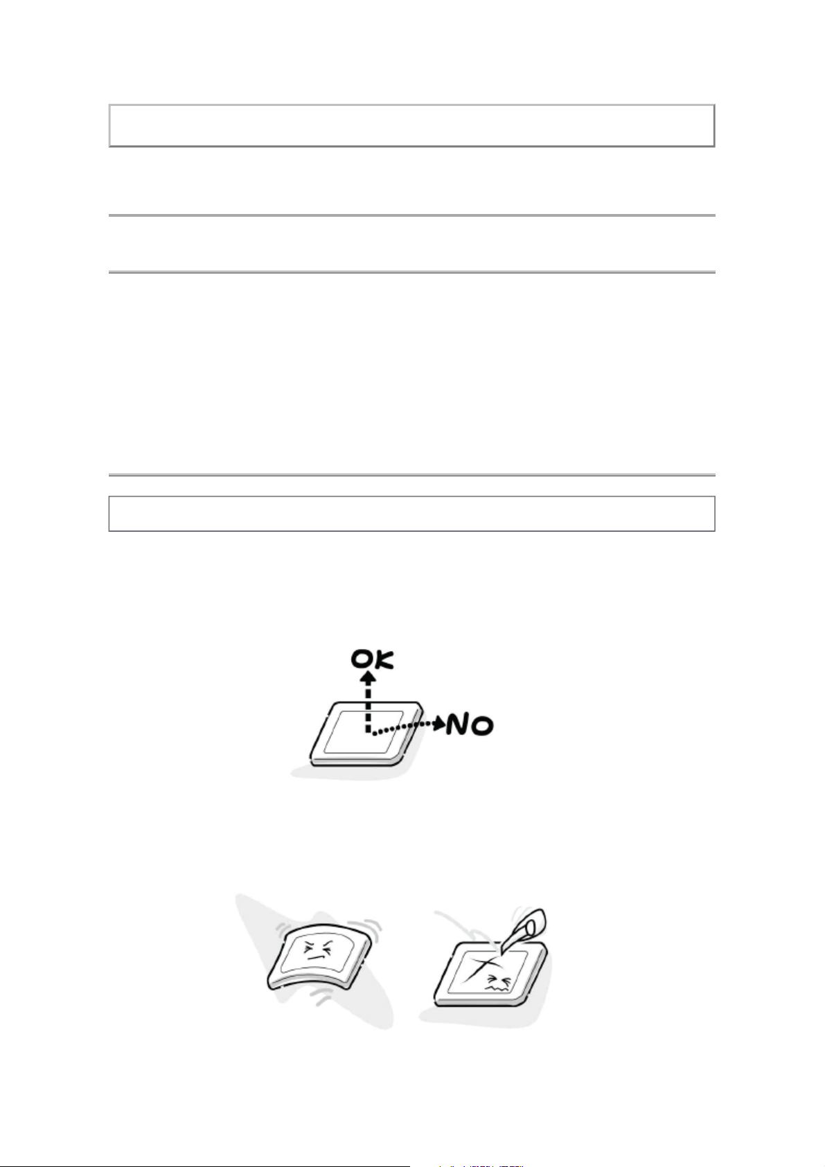
1. When attaching the LCD module to the LCD cover, position it appropriately and fasten at
the position where the display can be viewed most conveniently.
2. Carefully align the holes at all four corners of the LCD module with the corresponding holes
in the LCD cover and fasten with screws. Do not strongly push on the module because any
impact can adversely affect the performance. Also use caution when handling the polarized
screen because it can easily be damaged.
3. If the panel surface becomes soiled, wipe with cotton or a soft cloth. If this does not remove
Page 7
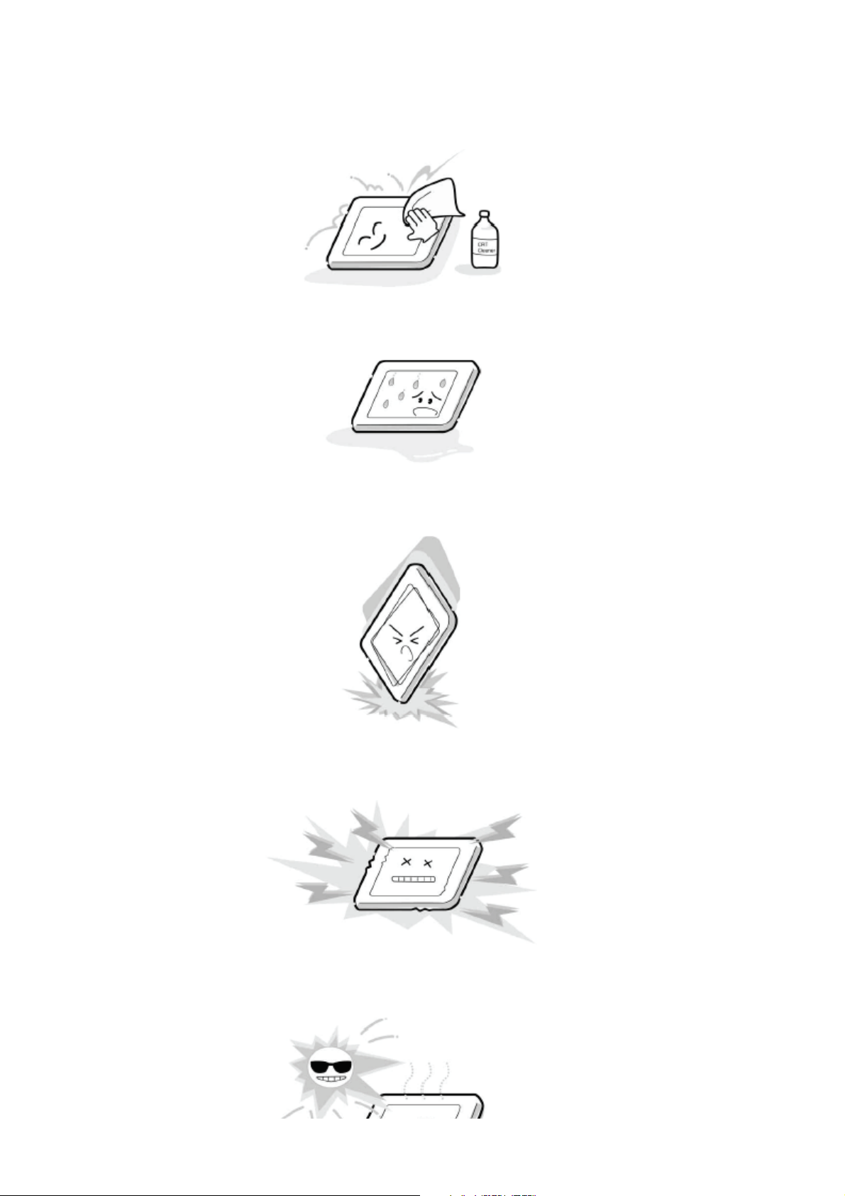
the soiling, breathe on the surface and then wipe again.
If the panel surface is extremely solied, use a CRT cleaner as a cleaner. Wipe off the panel
surface by drop the cleaner on the cloth. Do not drop the cleaner on the panel. Pay
attention not to scratch the panel surface.
4. Leaving water or other fluids on the panel screen for an extended period of time can result
in discoloration or stripes. Immediately remove any type of fluid from the screen.
5. Glass is used in the panel, so do not drop or strike with hard objects. Such actions can
damage the panel.
6. CMOS-LSI circuitry is used in the LCD module, so avoid damage due to static electricity.
When handling the module, use a wrist ground or anchor ground.
7. Do not expose the LCD module to direct sunlight or strong ultraviolet rays for an extended
period of time.
Page 8

8. Do not store the LCD module below the temperature conditions described in the
specifications. Failure to do so could result in freezing of the liquid crystal due to cold air or
loss of resilience or other damage.
9. Do not disassemble the LCD module. Such actions could result in improper operation.
10. When transporting the LCD module, do not use packing containing epoxy resin (amine) or
silicon resin (alcohol or oxim). The gas generated by these materials can cause loss of
polarity.
TOSHIBA WEB-ZEUS
>> terms and conditions >> privacy policy
Copyright © 1995-2012 TOSHIBA Corporation, All Rights Reserved.
Page 9

Page 10

P201 P202 CN1 CN12
1 24V 1 12V 1 +12V_NORMAL 1 PANEL_VCC
2 24V 2 12V 2 +12V_NORMAL 2 PANEL_VCC
3 24V 3 12V 3 +12V_NORMAL 3 PANEL_VCC
4 24V 4 GND 4 GND 4 PANEL_VCC
5 24V 5 GND 5 GND 5 OD_OCP_SEL
6 GND 6 GND 6 GND 6 PANEL_VCC
7 GND 7 5VSB 7 +5V_Standby 7 RXE4+
8 GND 8 5VSB 8 +5V_Standby 8 GND
9 GND 9 5VSB 9 +5V_Standby 9 RXE3+
10 GND 10 ACD 10 ACDetect 10 RXE4-
11 BRIGHT_ADJ 11 BD_PS_ON 11 GND 11 RXEC+
12 INV_ON_OFF 12 BRIGHT_ADJ 12 OCP_OUTPUT_PWM 12 RXE3-
13 INV_ON_OFF 13 INVERTER_ON_OFF 13 GND
14 PS_ON 14 STANDBY 14 RXEC-
15 RXE2+
16 GND
17 RXE1+
18 REX2-
19 REX0+
20 REX1-
21 GND
22 REX0-
23 RXO4+
24 GND
25 RXO3+
26 RXO4-
27 RXOC+
28 RXO3-
29 GND
30 RXOC-
31 RXO2+
32 GND
33 RXO1+
34 RXO2-
35 RXO0+
36 RXO1-
37 GND
38 RXO0-
39 BRIGHT_ADJ
40 OCP_OUTPUT_PWM
CN2
1 GND
2 LED_TIMER
3 LED_ON_OFF
4 LED_ON_OFF CN11
5 IRIN 1 SPK_R-
6 +5V_Standby 2 SPK_R+
3 SPK_L-
4 SPK_L+
CN202
1 +5V_STBY
2 IRIN
3 GND
4 LED_ON_OFF
5 LED_ON_OFF
6 LED_TIMER
IR_LED BORAD
Speaker
MAIN BOARD
PSU Unit
PANEL (T-CON)
PANEL INVERTER
Speaker
Page 11

TROUBLESHOOTING GUIDE
UNDER CONSTRUCTION
Note: Please check back in the future.
Print this page
TOSHIBA WEB-ZEUS
>> terms and conditions >> privacy policy
Copyright © 1995-2012 TOSHIBA Corporation, All Rights Reserved.
Page 12

FIRMWARE UPDATING PROCEDURE
Firmware Upgrade - USB
USB upgrade flow
1. Firmware upgrade.
Copy a Firmware BIN file to USB disk (root directory) with FAT 32.
For example the naming as below.
xx_xV_xL_DB_933x_022_REV00.bin, shall have difference version of firmware number
show on red.
2. Plug USB disk into TV USB port.
3. IR key MENU → SETUP → Software Upgrade → USB Upgrade.
During F/W upgrade will display percent on the screen when is finished will shown a
message on LCD screen then unplug USB disk. TV will auto reset and power on again.
Print this page
Note:
Not allow copy more then 1 versions of firmware in USB disk.
TOSHIBA WEB-ZEUS
>> terms and conditions >> privacy policy
Copyright © 1995-2012 TOSHIBA Corporation, All Rights Reserved.
Page 13

MODEL ID and PANEL ID
Print this page
Total digits
Max 14
YWK
Y : Year 8 2008
9 2009
A 2010
B 2011
C 2012
YWK
YWK
3 digits
·
·
·
Model_ID
xxx
3 digits
·
·
·
SERIAL
******
6 digits
(M00001~M99999)
Panel
**
2digits
WK : Week 01 WK01
02 WK02
03 WK03
04 WK04
53 WK53
Model/Panel Information
Model Model ID Panel ID Panel
19EL933RB K86 L1 LC185EXE-TEA1
19EL934RB K87 L1 LC185EXE-TEA1
23EL933RK L22 K1 LTM230HT10
·
·
·
·
·
·
23EL934RK L23 K1 LTM230HT10
26EL933B K90 L1 LC260EXN-SDA3
Page 14

26EL933G
K91L1LC260EXN
-
SDA3
26EL933RB K93 L1 LC260EXN-SDA3
26EL934G K94 L1 LC260EXN-SDA3
32EL933B L27 L1 LC320EXN-SEA1
32EL933G K96 L1 LC320EXN-SEA1
32EL933N K98 L1 LC320EXN-SEA1
32EL933RB K99 L1 LC320EXN-SEA1
32EL934G L01 L1 LC320EXN-SEA1
32EL934RB L02 L1 LC320EXN-SEA1
32HL933B L17 K1 LTA320HN03
32HL933G L16 K1 LTA320HN03
32HL933N L30 K1 LTA320HN03
32HL933RK L18 K1 LTA320HN03
40HL933B L20 K1 LTA400HM22
40HL933G L19 K1 LTA400HM22
40HL933N L31 K1 LTA400HM22
40HL933RK L21 K1 LTA400HM22
Model Model ID Panel ID Panel
32AV933G L03 L1 LC320WXN-SCC1
32AV933N L28 L1 LC320WXN-SCC1
32AV933RB L05 L1 LC320WXN-SCC1
32AV934G L06 L1 LC320WXN-SCC1
32AV934RB L07 L1 LC320WXN-SCC1
32LV933G L08 A1 T315HW04 V4(REV.6)
32LV933N L10 A1 T315HW04 V4(REV.6)
32LV933RB L11 A1 T315HW04 V4(REV.6)
K1 LTA400HM01-R
40LV933G L12
C1 V400HJ2-L01
K1 LTA400HM01-R
40LV933N L29
C1 V400HJ2-L01
K1 LTA400HM01-R
40LV933RB L14
C1 V400HJ2-L01
Page 15

Panel vendor
Marking Panel Vendor Marking Panel Vendor Marking Panel Vendor
A AUO J S SHARP
B K SAMSUNG T
C CMO L LPL/LGD U
D M V
E N W
F P CPT X
G Q Y
H IPS R Z
TOSHIBA WEB-ZEUS
>> terms and conditions >> privacy policy
Copyright © 1995-2012 TOSHIBA Corporation, All Rights Reserved.
Page 16

DESTINATION SETTING CHANGE
Whenever replacing the Main PCB with new one, perform this procedure.
1. IR Key MENU → APPLICATIONS → Sleep Timer → OK.
2. When display _ _ : _ 0 input 4 numbers 2766.
The Factory menu will display.
Print this page
3. Move to Tag "3" by Right/Left Arrow key on the Remote.
4. Select "Model Type" cell.
Page 17

5. Select the appropriate model type by Right/Left Arrow key on the Remote. Model type is
written on the rating label.
6. Select "Reset to Def".
7. Select "Yes" and press "OK" button on the Remote.
Page 18

TOSHIBA WEB-ZEUS
>> terms and conditions >> privacy policy
Copyright © 1995-2012 TOSHIBA Corporation, All Rights Reserved.
Page 19

Print this page
VR
Variable Resistor
PARTS LIST
Precaution
WARNING: BEFORE SERVICING THIS CHASSIS, READ THE "SAFETY PRECAUTION"
AND "PRODUCT SAFETY NOTICE".
CAUTION: The international hazard symbols " " in the schematic diagram and the
parts list designate components which have special characteristics important for safety
and should be replaced only with types identical to those in the original circuit or
specified in the parts list.
The mounting position of replacements is to be identical with originals.
Before replacing any of these components, read carefully the "SAFETY PRECAUTION"
AND "PRODUCT SAFETY NOTICE".
Do not degrade the safety of the receiver through improper servicing.
Note:
The part number must be used when ordering parts, in order to assist in processing, be
sure to include the Model number and Description.
The PC board assembly with mark is no longer available after the end of the production.
Abbreviations
Capacitors CD : Ceramic Disk
Resistors CF : Carbon film
OMF : Oxide Metal Film
PF : Plastic Film
CC : Carbon Composition
:
EL : Electrolytic
MF : Metal Film
FR : Fusible Resistor
All CD and PF capacitors are ±5 %, 50 V and all resistor, ±5 %, 1/6 W unless otherwise noted.
Page 20

TOSHIBA WEB-ZEUS
>> terms and conditions >> privacy policy
Copyright © 1995-2012 TOSHIBA Corporation, All Rights Reserved.
Page 21

Currently there are no updates available.
Please check back at a later time for any future updates.
 Loading...