

Page 1

1-1
1.1 Features
The 400CS/400CDT (400 Series) is one of the lightest and most advanced portable computers
available. Utilizing advanced technology and high-speed components, the 400 series offers
multimedia functions, excellent display legibility, battery operation, and IBM PC/AT compatibility. The 400 series system unit has the following features:
❑ Microprocessor
An Intel Pentium® processor 75 MHz with Voltage Reduction Technology (VRT)
that operates at 75 MHz and 2.9 volts.
❑ Disk storage
An internal 810 million byte (770 MB) Hard Disk Drive (HDD). A 3.5-inch Floppy
Disk Drive (FDD) supports 2HD (1.44 MB) floppy disks and 2DD (720 KB) floppy
disks. The FDD can also be installed in an attachment (option with 400CS) for connection as an external device.
❑ CD-ROM Drive (option with 400CS)
A full-size, quadruple-speed CD-ROM drive module can be installed instead of the
FDD module. The CD-ROM drive contains an ATAPI (AT attachment packet interface) interface controller, and supports the following formats: audio CD, photo CD,
and ISO 9660.
❑ Memory
Standard with 8 MB of CMOS RAM. This includes 640 KB of conventional memory
and 7360 KB of extended memory, which can be utilized as expanded memory compatible with the Lotus/Intel/Microsoft Expanded Memory Specification (LIM-EMS).
❑ Display
The 400CS has a 10.4" full color, Dual-scan Supertwist Nematic (DSTN) LCD 640 X
480 pixels. The 400CDT has a 10.4" full color, Thin Film Transistor (TFT) LCD 640
X 480 pixels. The built-in display controller supports Video Graphics Array (VGA)
for the internal LCD and Super VGA (SVGA) for the external CRT.
❑ Keyboard
An-easy-to-use 82/84-key keyboard provides a numeric keypad overlay for fast numeric data entry or for cursor and page control. The computer’s keyboard supports
software that uses a 101- or 102-key enhanced keyboard.
400 Series
Page 2

1-2
❑ Batteries
Three different batteries: a Li-Ion main battery, a backup battery (for memory
backup), and a RTC battery (Real Time Clock).
❑ Expansion memory slot
An optional 8, 16, or 32 MB memory module can be installed in the memory slot.
❑ Parallel port
Can be used to connect a Centronics compatible printer or other parallel device;
supports ECP (Enhanced Capabilities Port) conforming to IEEE·1284.
❑ Serial port (9-pin)
The serial controller is 16550UART compatible. This port can be used to connect such
serial devices as a serial printer, serial mouse, or external modem.
❑ RGB port
The female, 15-pin, D-shell connector can be connected to an external SVGA monitor.
❑ Ext. Keyboard/Mouse port
Either a PS/2 compatible keyboard or a PS/2 compatible mouse can be connected to
this port. The computer automatically recognizes which device is connected.
❑ FDD port
Enables a connection of the external FDD attachment if the CD-ROM module is
installed inside the system unit.
❑ PC card slot
Supports up to two Personal Computer Memory Card International Association
(PCMCIA) standard version release 2.0 cards. The upper and lower slots can each
accommodate one Type II (5.0 mm) card, or the lower slot can accommodate one
Type III (10.5 mm) card when the upper slot is empty.
❑ Enhanced port replicator port
Enables connection of an enhanced port replicator. The enhanced port replicator has
two PC card slots (Type III), and expands connections to the following devices: PS/2
keyboard, PS/2 mouse, serial port, parallel port, external CRT, joystick/MIDI port,
audio line-in, audio line-out, headphone, external FDD, AC-in, and AC-out.
400 Series
Page 3

1-3
❑ AccuPoint
A pointer control stick, located in the center of the keyboard, provides convenient
control of the cursor without requiring desk space for a mouse.
❑ Infrared port
This machine incorporates an IrDA1.0 (115.2Kbps supported) standard infrared
transmitter and receiver.
❑ Sound System
A Sound BlasterTM ProTM compatible sound system provides capability to record sound
and play it back with a built-in microphone and speaker. The sound system is equipped
with a volume control dial, headphone jack, microphone jack, and audio line-in jack.
400 Series
Page 4
1-4
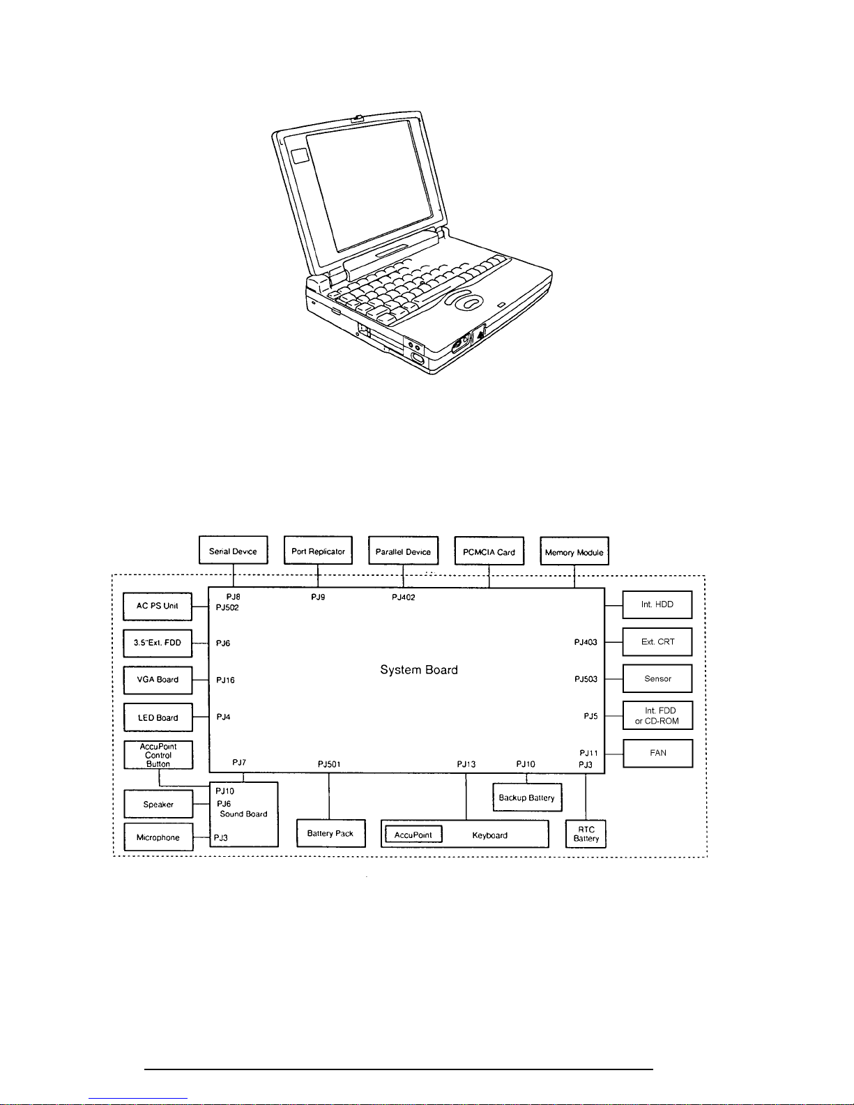
The 400 Series Personal Computer is shown in figure 1-1.
Figure 1-1 400 series personal computer
The 400 system configuration is shown in figure 1-2.
Figure 1-2 400 system unit configuration
400 Series
Page 5
1-5
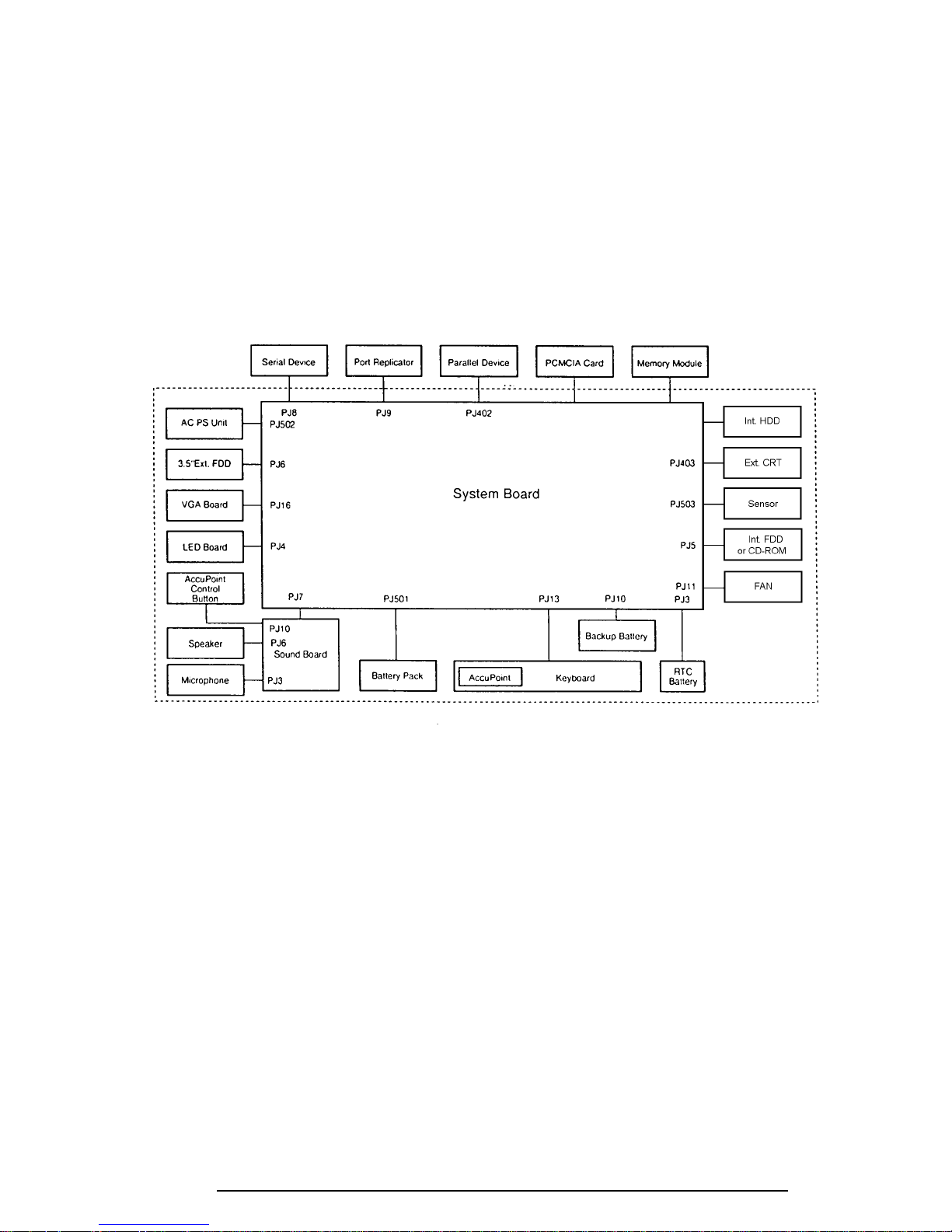
1.2 System Unit Block Diagram
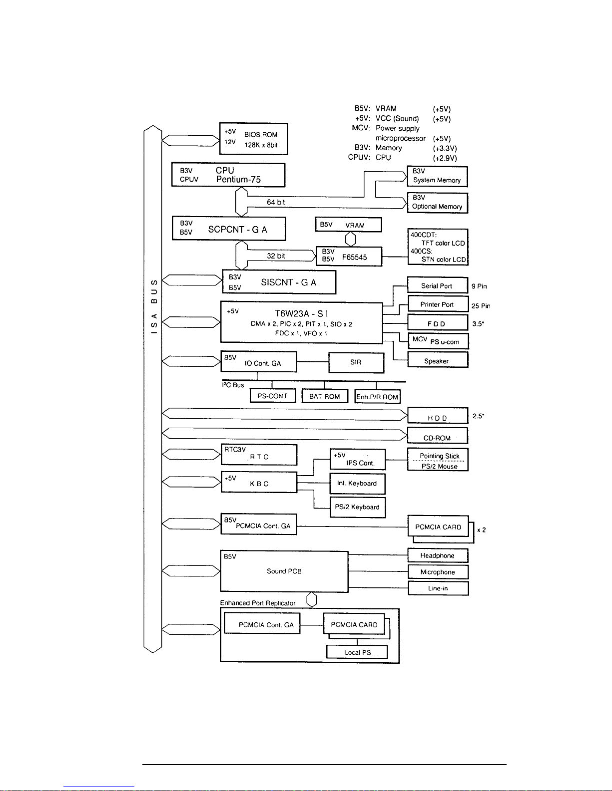
Figure 1-3 is a block diagram of the 400 series system unit.
Figure 1-3 400 series system board block diagram
400 Series
Page 6

1-6
The 400 series system board is composed of the following major components:
❑ One Intel Pentium processor 75 MHz with VRT 64-bit microprocessor
Intel Pentium processor operates at 75 MHz and 2.9 volts.
❑ Standard RAM
8 MB, four 1Mx16-bit chips
3.3 volt operation
No parity bit
Access time 70 ns
Data transfer is 64-bit width
EDO (extended data output) supported
❑ BIOS ROM (Flash EEPROM)
128 MB (one 128Kx8-bit chip) memory
64 KB in the ROM are used for system BIOS
40 KB in the ROM are used for VGA BIOS
24 KB in the ROM are reserved
Access time 150 ns
Data transfer is 8-bit width
❑ Video RAM
1 MB (Two 256Kx16-bit DRAM)
5 volt operation
❑ Optional memory
One expansion memory slot is available for 8, 16, and 32 MB memory modules, which
may consist of 1 MBx16-bit chips
Total maximum memory size is 40 MB (if a 32 MB memory module is installed)
3.3 volt operation
No parity bit
Access time 60 ns
Data transfer is 64-bit width
EDO (extended data output) supported
❑ One super integration (SI)
The following components:
- Two DMACs 82C37 equivalent
- Two PICs 82C59 equivalent
- Two UART 16550 equivalent
- One PIT 82C54 equivalent
- One FDC TC8565 equivalent
- One VFO TC8568 equivalent
- One I/O port decode
- One SIO port control
- One printer port control supported ECP
- One FDD control
- One speaker control
- One power communication control
400 Series
Page 7

1-7
❑ System Controller Gate Array (SCPCNT-GA)
This gate array has the following functions:
CPU control
SMI control
CPU clock control
Memory control
64-bit bus memory control
32-bit bus memory control
Bus control
64-bit data bus <==>32-bit data bus
32-bit local bus control
Address latch control
I/O register control
Processing speed control
❑ ISA Bus Controller Gate Array (SISCNT3-GA)
This gate array has the following functions:
Bus control
32-bit data bus <==> 16-bit data bus
ISA bus interface control
ISA bus access control
DMAC control
DMA address generation
I/O control
Suspend/Resume sequence
Memory control
IAS bus interface control
Refresh address generation
I/O register control
Suspend/Resume sequence
❑ PCMCIA Controller Gate Array
This gate array has the following functions:
PCMCIA memory card control
PCMCIA I/O card control
❑ I/O Controller Gate Array (IOCNT-GA)
This gate array has the following functions:
Internal Communication controller
KBC, main CPU communication register file
KBC interrupt controller
KBC communication controller
I2C bus control
Others
Speaker volume adjust PWM control
Sound board interface
BIOS-ROM interface
SIM control
IrDA (SIR) control
400 Series
Page 8

1-8
❑ Video Controller
Chips & Technologies F65546 is used
Controls internal TFT/STN color LCD and external SVGA compatible CRT
❑ Keyboard Controller (KBC)
One M38802M4 chip is used
This KBC includes the keyboard scan controller and keyboard interface controller
The KBC controls the internal keyboard, external keyboard, PS/2 mouse
❑ Real Time Clock (RTC)
One T9934 chip is used
The T9934 has 128 of bytes memory
Fourteen bytes of memory are used for the calendar and clock, the remaining 114
bytes are used for the system configuration data
400 Series
Page 9
1-9
1.3 3.5-inch Floppy Disk Drive
The 400 series 3.5-inch Floppy Disk Drive (FDD) is a thin, high-performance reliable drive
that supports 720-KB (formatted) 2DD and 1.44-MB (formatted) 2HD 3.5-inch floppy disks.
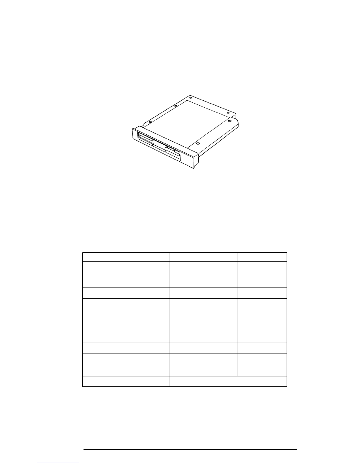
The 400 series FDD is shown in figure 1-4.
Figure 1-4 3.5-inch FDD
The specifications for the FDD are listed in table 1-1.
Table 1-1 3.5-inch FDD specifications
Item 2-MB mode 1-MB mode
Storage capacity (KB)
Unformatted 2,000 1,000
Formatted 1,311 737
Number of heads 2 2
Number of cylinders 80 80
Access time (ms)
Track to track 3 3
Average 181 181
Head settling time 15 15
Recording track density (tpi) 135 135
Data transfer rate (Kbps) 500 250
Rotation speed (rpm) 300 300
Recording method Modified Frequency Modulation (MFM)
400 Series
Page 10
1-10
1.4 2.5-inch Hard Disk Drive
The 770 MB Hard Disk Drive (HDD) is a random access non-volatile storage device. It has a
non-removable 2.5-inch magnetic disk and mini-winchester type magnetic heads.
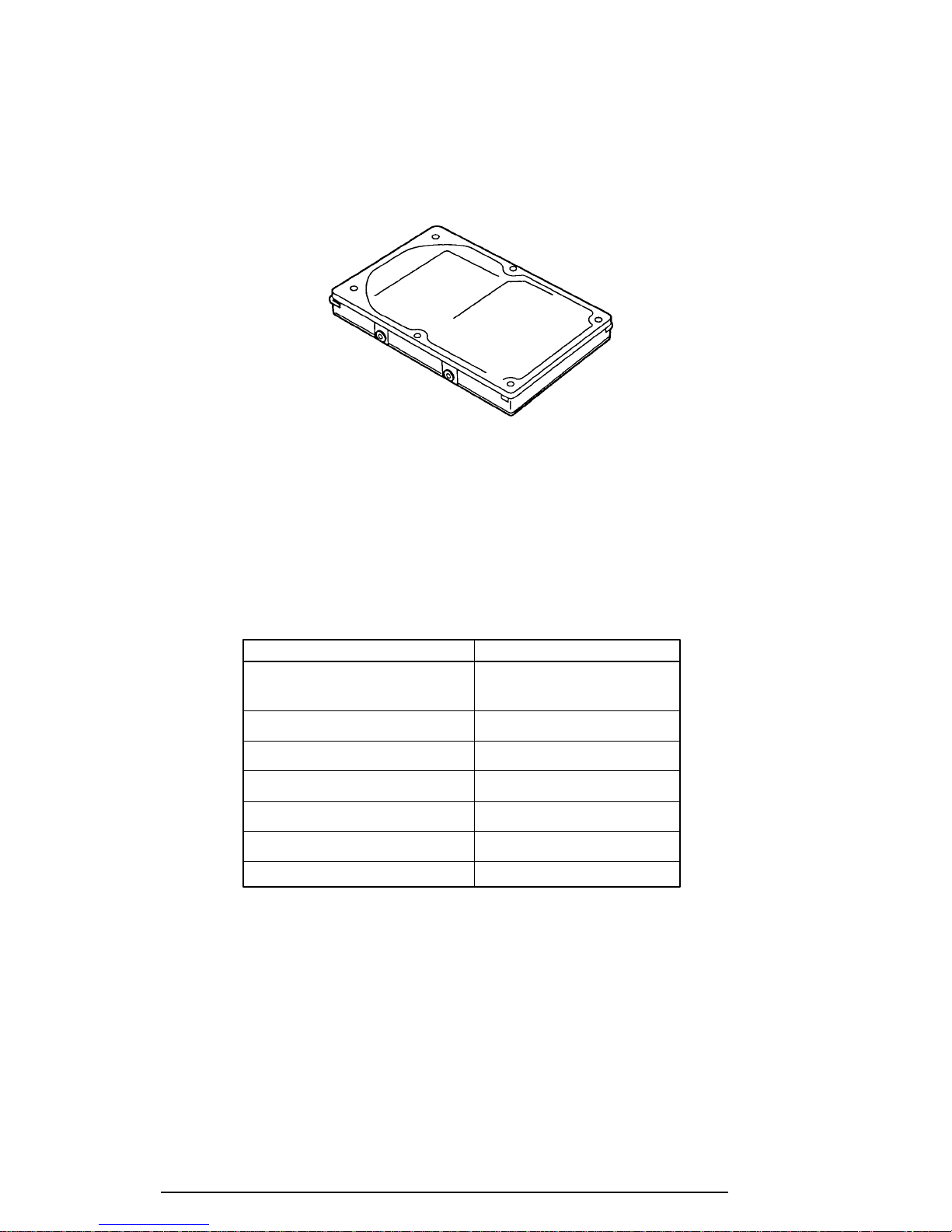
The 400 series is shown in figure 1-5.
Figure 1-5 2.5-Inch HDD
Specifications for the HDD are listed in table 1-2.
Table 1-2 2.5-inch HDD specifications
Items (MK1926FCV)
Storage capacity (MB)
Formatted 815
Number of disks 3
Data heads 6
Data surfaces 6
Bytes per sector 512
Rotation speed (rpm) 4200
Recording method 8-9 RLL
400 Series
Page 11
1-11
1.5 Keyboard
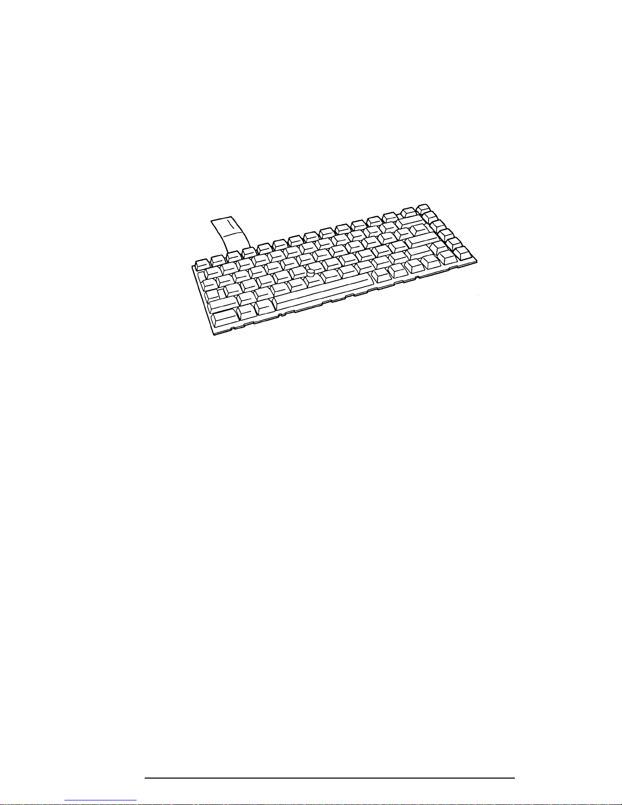
The 82-(USA) or 84-(European) keyboard is mounted on the 400 series system unit. The
keyboard is connected to the keyboard controller on the system board through a 25-pin flat
cable. The 400 series pointer control stick, located in the center of the keyboard, provides
convenient control of the cursor without requiring desk space for a mouse. The keyboard is
shown in figure 1-6.
See Appendix E for optional keyboard configurations.
Figure 1-6 Keyboard
400 Series
Page 12
1-12
1.6 CD-ROM Drive
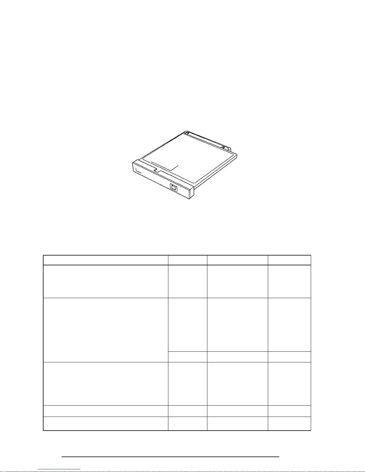
The 400 series internal CD-ROM drive accommodates either 12 cm (4.72") or 8 cm (3.15")
CDs (option with 400CS). It provides high-performance, quadruple-speed play (reads 300KB
per second). This drive supports the following formats:
Audio CD
Photo CD
ISO 9660
The 400 series CD-ROM drive is shown in figure 1-7.
Figure 1-7 CD-ROM
The specifications for the CD-ROM drive are listed in table 1-3.
Table 1-3 CD-ROM specifications
Item 1✕ mode 2✕ mode 4✕ mode
Data Capacity (bytes/block)
Mode 1 2,048 2,048 2,048
Mode 2 2,336 2,336 2,336
Transfer Rate
Sustained Block transfer speed (blocks/s) 75 150 300
Sustained Data transfer speed (kbytes/s)
Mode 1 150 300 600
Mode 2 171 342 684
ATAPI Burst (Mbytes/s) 3.33* 3.33* 3.33*
Access time (ms)
Average Random Access 360 255 210
Average Random Seek 250 210 185
Average Full Stroke Access 540 450 355
Rotation speed (rpm) 200 to 530 400 to 1,060 800 to 2,120
Data Buffer Capacity (Kbytes) 128 128 128
*(PIO mode 0)
400 Series
Page 13
1-13
1.7 STN Color LCD (400CS)
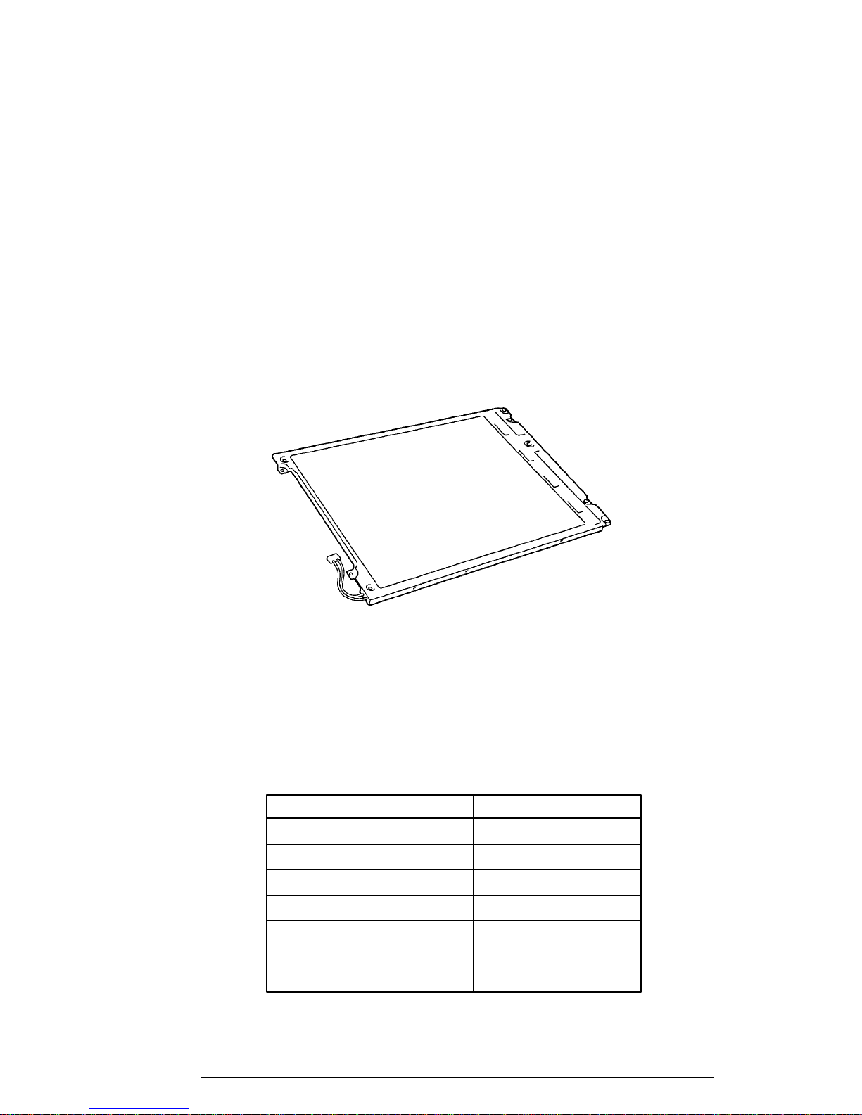
The STN Color Liquid Crystal Display (LCD) contains an LCD module, a Fluorescent Lamp
(FL), and an FL inverter board.
1.7.1 STN Color LCD Module
The 400CS STN color LCD is backlit and supports 640x480 pixels with a Video controller.
This video controller includes the functions of Video Graphics Array (VGA).
The 400CS LCD receives vertical and horizontal synchronizing signals, 16-bit data signal, 8bit upper block data signal, 8-bit lower block data signal, and has a shift clock for data
transmission. All signals are CMOS-level compatible.
The STN LCD is shown in figure 1-8.
Figure 1-8 STN color LCD
The specifications for the LCD are listed in table 1-4.
Table 1-4 STN color LCD specifications
Item Specifications
Number of Dots (dots) 640x480
Dot pitch (mm) 0.33x0.33
Display area (mm) 217.2 (W)x164.4 (H)
Contrast (Typically) 20:1
FL current (mA) 5.0/3.0
FL frequency (KHz) 40
(Bright/Semi-bright)
400 Series
Page 14
1-14
1.7.2 STN Color Fluorescent Lamp (FL) Inverter Board
The FL inverter board supplies high frequency current to light the LCD’s Fluorescent Lamp.
The specifications for the FL inverter are listed in table 1-5.
Table 1-5 STN color FL inverter board specifications
Item Specifications
Input Voltage (VDC) 5
Power (W) 4.25
Output Voltage (VAC) 1,100
Current (mA) 5.0
Frequency (KHz) 40
400 Series
Page 15
1-15
1.8 TFT Color LCD (400CDT)
The TFT Color Liquid Crystal Display (LCD) contains an LCD module, a Fluorescent Lamp
(FL), and an FL inverter board.
1.8.1 LCD Module
The 400CDT TFT color LCD supports 640x480 pixels with an internal display controller.
This controller includes the functions of Video Graphics Array (VGA) and Super VGA
(SVGA) for external display.
The 400CDT LCD receives 18-bit data signals, data enable signals, and has a shift clock for
data transmission. All signals are CMOS-level compatible.
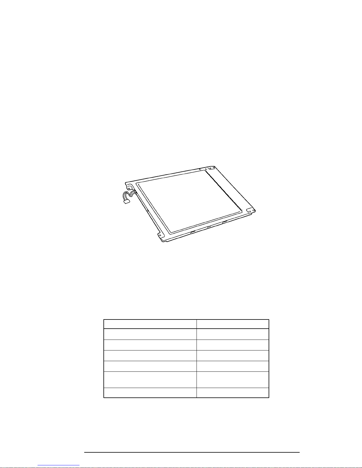
The TFT LCD is shown in figure 1-9.
Figure 1-9 TFT color LCD
The specifications for the LCD are listed in table 1-6.
Table 1-6 TFT color LCD specifications
Item Specifications
Number of dots (dots) 640x480
Dot pitch (mm) 0.33 (W)x0.33 (H)
Display area (mm) 211.2 (W)x158.4 (H)
Contrast 100:1 (minimum)
FL current (mA) 4.6/2.8
FL frequency (KHz) 40
(Bright/Semi-bright)
400 Series
Page 16
1-16
1.8.2 Fluorescent Lamp (FL) Inverter Board
The FL inverter board supplies high frequency current to light the LCD’s Fluorescent Lamp.
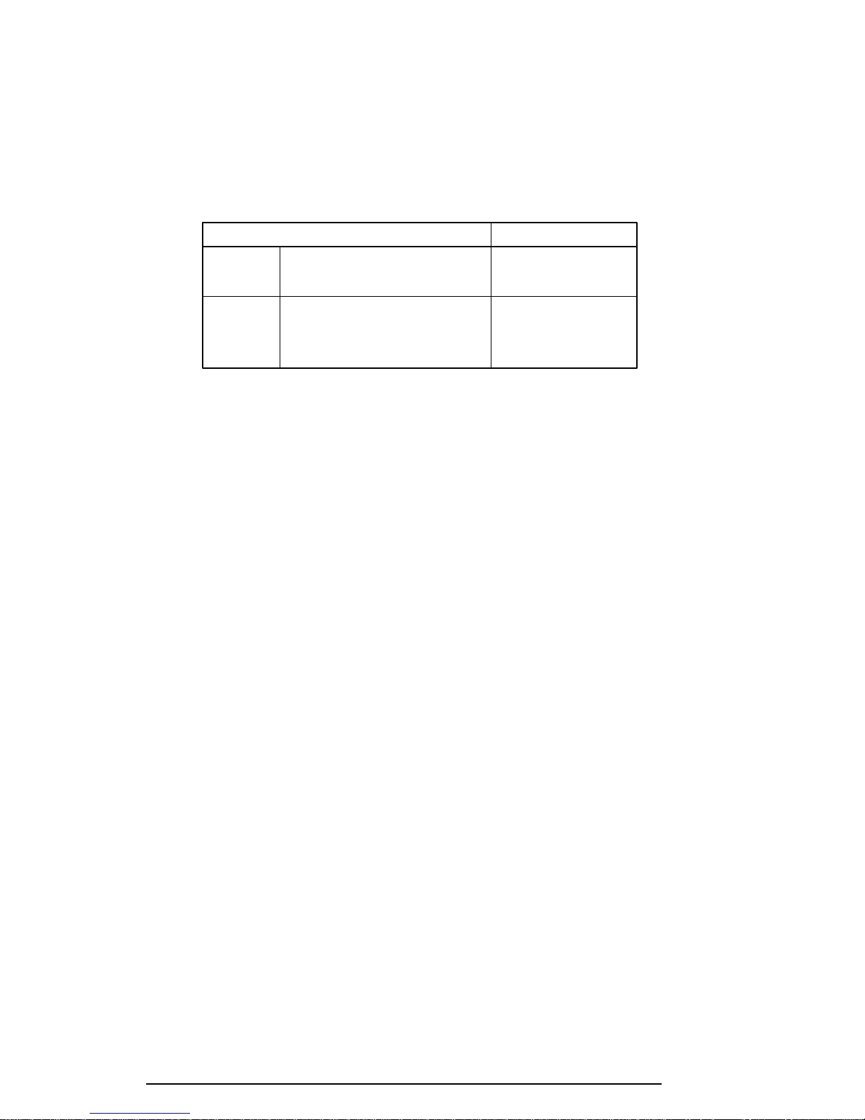
The specifications for the FL inverter are listed in table 1-7.
Table 1-7 FL inverter board specifications
Item Specifications
Input Voltage (VDC) 5
Power (W) 4.25
Output Voltage (VAC) 1,100 (r.m.s.)
Current (mA) 4.6/2.8
Frequency (KHz) 40
400 Series
Page 17
1-17
1.9 Power Supply
The power supply supplies five kinds of voltages to the 400 series system board. The power
supply has one microprocessor, which operates at 500 KHz, and performs the following
functions:
1. Determines if the AC cable or battery is connected to the computer.
2. Detects AC output and circuit malfunctions.
3. Controls the LED icon and speaker.
4. Turns the battery charging system on and off and detects a fully charged battery.
5. Determines if the power can be turned on and off.
6. Provides more accurate detection of a low battery.
7. Calculates the remaining battery capacity.
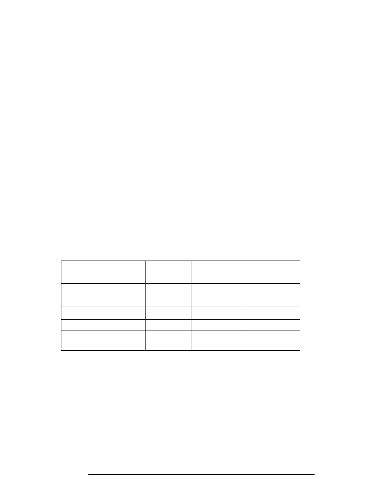
The power supply output rating is specified in table 1-8.
Table 1-8 Power supply output rating
Use for Name voltage tolerance
System logic, FDD, HDD, VCC +5 ±5
Display
CPU CPUV +2.9 ±5
Flash ROM, PCMCIA 12V +12 ±5
CPU, RAM, GA B3V +3.3 ±0.3V
VRAM, GA B5V +4.7 ±5
DC Regulation
(%)
400 Series
Page 18
1-18
1.10 Batteries
The 400 series has three types of batteries:
❑ Main battery pack
❑ Backup battery
❑ Real Time Clock (RTC) battery
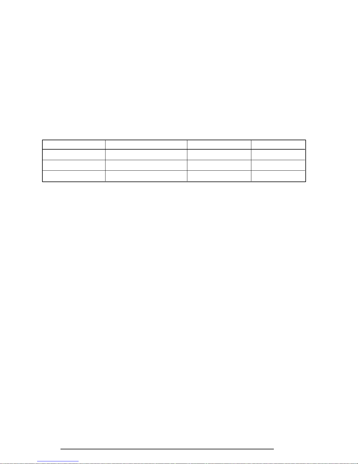
Battery specifications are listed in table 1-9.
Table 1-9 Battery specifications
Battery name Material Output voltage Capacity
Main battery Lithium-Ion 10.8 V 1,200 mAH
Backup battery Nickel Metal Hydride 7.2 V 110 mAH
RTC battery Nickel Metal Hydride 3.6 V 30 mAH
1.10.1 Main Battery
The removable main battery pack is the computer’s main power source when the AC power
cord is not attached. The main battery recharges the backup battery. The backup and main
battery maintain the state of the computer when you enable AutoResume.
❏ Battery Icon
The Battery icon is located on top of the back rim of the 400 series. The icon shows
the status of the removable battery pack.
The status of each can be determined by color:
Orange The battery is being charged. (AC power cord is attached.)
Green The battery is fully charged. (AC power cord is attached.)
Blink orange The battery is low when the power is on.
No light Under any other conditions, the LED does not light.
400 Series
Page 19
1-19
1.10.2 Battery Charging Control
Battery charging is controlled by a power supply microprocessor that is mounted on the
power supply. The microprocessor controls whether the charge is on or off and detects a full
charge when the AC power cord and battery are attached to the computer. The system
charges the battery using quick charge or trickle charge.
❏ Quick Battery Charge
When the AC power cord is attached, there are two types of charge: quick charge
when the system is powered off and trickle charge when the system is powered on.
Table 1-10 Time required for quick charges
Charging time
Power off About 2 to 3 hours
Power on About 5 to 8 hours
If one of the following occurs, the battery quick-charge process stops:
1. The battery becomes fully charged.
2. The battery is removed.
3. The battery or AC output voltage is abnormal.
4. The charge current is abnormal.
❏ Trickle Battery Charge
When the main battery is fully charged and the AC power cord is attached, the power
supply microprocessor automatically changes from quick charge to trickle charge.
400 Series
Page 20
1-20
1.10.3 Backup Battery
The backup battery maintains data for AutoResume. The power source used to back up the
AutoResume data is determined according to the following priority:
AC power > Main battery > Backup battery
The backup battery is charged by the main battery or AC power cord. Table 1-11 shows the
charging time and data preservation period of the backup battery.
Table 1-11 Backup battery charging/data preservation time
Time
Charging Time Power On 20 H
Power Off 20 H
Data preservation period (full charge) 4 H
1.10.4 RTC Battery
The RTC battery provides power to keep the current date, time, and other setup information
in memory while the computer is turned off. Table 1-12 shows the charging time and data
preservation period of the RTC battery.
Table 1-12 RTC battery charging/data preservation time
Time
Charging Time With AC power 48 H
or main battery
Data preservation period (full charge) Doesn’t charge
400 Series
Page 21

2-1
2.1 Troubleshooting
Chapter 2 describes how to determine if a Field Replaceable Unit (FRU) in the 400 series is
causing the computer to malfunction. The FRUs covered are:
1. Power Supply
2. System Board
3. Sound Board
4. Floppy Disk Drive
5. Hard Disk Drive
6. Keyboard
7. Display
8. VGA Board
9. CD-ROM Drive
The Diagnostics Disk operations are described in Chapter 3 and detailed replacement procedures are given in Chapter 4.
The following tools are necessary for implementing the troubleshooting procedures:
1. A 400 series Diagnostics Disk
2. A Phillips screwdriver (2 mm)
3. A Toshiba MS-DOS system disk(s)
4. A 2DD or 2HD formatted work disk for floppy disk drive testing
5. A cleaning kit for floppy disk drive troubleshooting
6. A printer port LED
7. An RS-232-C wraparound connector
8. A printer wraparound connector
9. A multimeter
10. An external CRT
400 Series
Page 22

2-2
2.2 Troubleshooting Flowchart
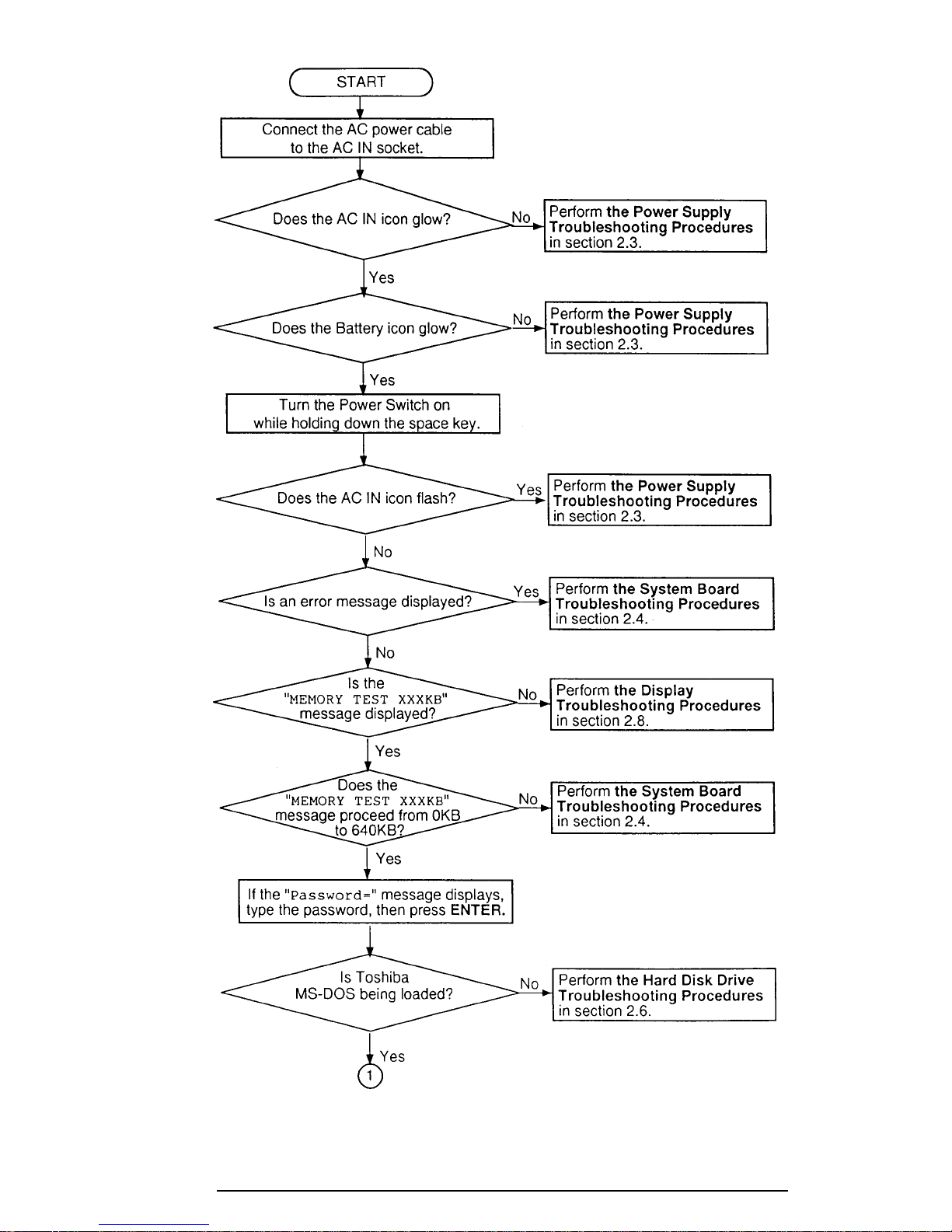
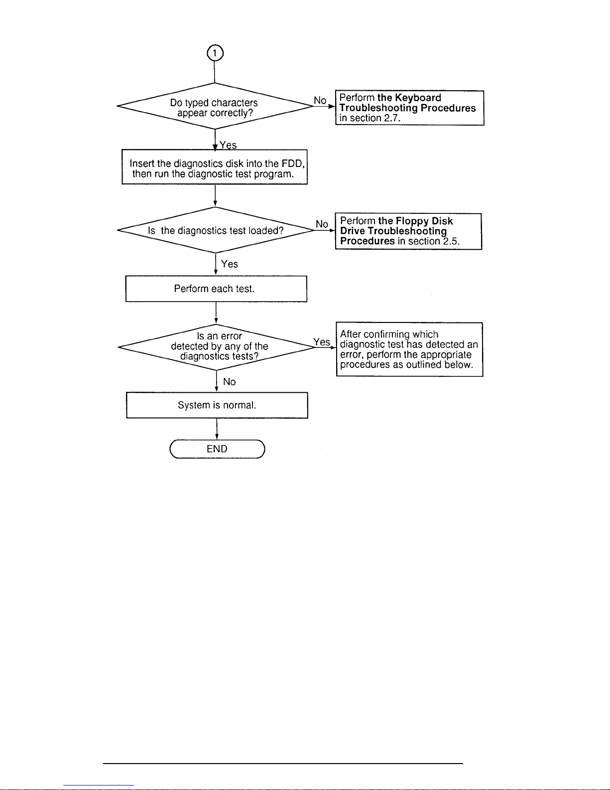
Use the flowchart in figure 2-1 as a guide for determining which troubleshooting procedures
to execute. Before going through the flowchart steps, do the following:
❑ Verify with the customer that Toshiba MS-DOS is installed on the hard disk. Non-
Toshiba operating systems can cause the computer to malfunction.
❑ Make sure all optional equipment is disconnected from the computer.
❑ Make sure the floppy disk drive is empty.
400 Series
Page 23
400 Series
2-3
Figure 2-1 Troubleshooting flowchart (1/2)
Page 24
2-4
Figure 2-1 Troubleshooting flowchart (2/2)
If the diagnostics program cannot detect an error, the problem may be intermittent. The
Running Test program should be executed several times to isolate the problem. Check the
Log Utilities function to confirm which diagnostic test detected an error(s), then perform the
appropriate troubleshooting procedures as follows:
1. If an error is detected on the system test, memory test, display test, ASYNC test,
printer test, or real timer test perform the system board troubleshooting procedures in section 2.4.
2. If an error is detected on the floppy disk test, perform the floppy disk drive
troubleshooting procedures in section 2.5.
3. If an error is detected on the hard disk test, perform the hard disk drive
troubleshooting procedures in section 2.6.
4. If an error is detected on the keyboard test, perform the keyboard troubleshooting
procedures in section 2.7.
400 Series
Page 25

2-5
5. If an error is detected on the display test, perform the display troubleshooting
procedures in section 2.8.
6. If an error is detected on the CD-ROM test, perform the CD-ROM drive troubleshooting procedures in section 2.9.
400 Series
Page 26

2-6
2.3 Power Supply Troubleshooting
The 400 series power supply controls many functions and components in the 400 series. To
determine if the power supply is functioning properly, start with Procedure 1 and continue
with the other Procedures as instructed. The procedures described in this section are:
Procedure 1: AC IN Icon Check
Procedure 2: Battery Icon Check
Procedure 3: AC PS Unit Replacement Check
Procedure 1 AC IN Icon Check
The 400 series AC PS unit converts AC power to DC power and contains a charging circuit
which charges the 400 series batteries. The AC power cord connects to the AC IN socket
connector on the back side of the computer. When the AC power cord is connected to the
400 series and the power is turned off, the AC charges the batteries.
The AC IN icon displays whether or not the AC power cord is connected and supplying
power.
When the AC IN icon is green, the AC power cord is connected and supplying power to the
400 series.
If the AC IN icon does not light, the AC power cord is not supplying power to the 400 series
or the AC power cord is not attached to the 400 series, go to Check 1.
If the AC IN icon is flashing orange, the AC power cord’s voltage supply is abnormal or the
power supply is not functioning properly, go to Check 2.
If any of the above indicator conditions are abnormal, make sure the icon lights are not burned
out before performing the following checks:
Check 1 Make sure the correct AC power cord is firmly plugged into the AC IN socket on
the back of the computer.
Check 2 If the AC IN icon flashes orange when the AC power cord is connected, output
voltage is abnormal. Connect a new AC power cord and turn the 400 series on
again to verify the indicator condition.
Check 3 The battery pack may be malfunctioning. Replace the battery pack with a new one
and turn the computer on again. If the problem still exists, go to Procedure 2.
400 Series
Page 27

2-7
Procedure 2 Battery Icon Check
The Battery icon shows the battery charging status. The Battery icon, identified by a battery
icon on the front of the computer, glows orange when the AC power cord is charging the 400
series battery pack.
If the Battery icon glows green, the AC power cord is connected and the battery is fully
charged.
If the Battery icon glows orange, the AC power cord is connected and the battery is being
charged.
If the Battery icon does not glow, go to Check 1.
Check 1 Make sure the AC power cord is firmly plugged into the AC IN socket and wall
outlet. If these cables are connected correctly, go to Check 2.
Check 2 Make sure the battery pack is installed in the computer correctly. If the battery
pack is installed correctly, go to Check 3.
Check 3 Remove the battery pack and check that the battery and system board terminals
are clean and not bent.
If the battery and/or system board terminal appears dirty, clean it/them gently with
a cotton swab dipped in alcohol.
If either terminal looks bent or damaged, replace the battery or system board.
If the terminals are clean and not bent, go to Check 4.
Check 4 Connect a new AC power cord. If the Battery icon still does not glow, go to
Check 5.
Check 5 Install a new battery pack. If the Battery icon still does not glow, go to Procedure
3.
Procedure 3 AC PS Unit Replacement Check
Power is supplied to the system board through the AC IN plug located on the AC PS unit. If
the AC PS unit is damaged, replace it.
Refer to chapter 4 for instructions on how to disassemble the 400 series, and then perform the
following checks:
Check 1 Replace the AC PS unit with a new one and restart the system. If the system is
still not functioning properly, perform Check 2.
Check 2 Replace the system board with a new one and restart the system. If the problem
still exists, other FRUs may be damaged.
400 Series
Page 28

2-8
2.4 System Board and Sound Board Troubleshooting
This section describes how to determine if the system board and sound board are defective or
not functioning properly. Start with Procedure 1 and continue with the other procedures as
instructed. The procedures described in this section are:
Procedure 1: Message Check
Procedure 2: Printer Port LED Check on Boot Mode
Procedure 3: Printer Port LED Check on Resume Mode
Procedure 4: Diagnostic Test Program Execution Check
Procedure 5: Replacement Check
Procedure 1 Message Check
When the power is turned on, the system performs the Initial Reliability Test (IRT) installed in
the BIOS ROM. The IRT tests each IC on the system board and initializes it.
❑ If an error message is shown on the display, perform Check 1.
❑ If there is no error message, go to Procedure 2.
❑ If the Toshiba MS-DOS is properly loaded, go to Procedure 3.
Check 1 If one of the following error messages is displayed on the screen, press the F1 key
as the message instructs. These errors occur when the data is lost or when the
system configuration preserved in the RTC memory (CMOS type memory) is not
the same as the actual configuration.
If you press the F1 key as the message instructs, the system configuration in the
RTC memory configuration is set to the default setting. If error message (b)
appears often when the power is turned on, replace the RTC battery. If any other
error message is displayed, perform Check 2.
(a) *** Bad HDD type ***
Check system. Then press [F1] key ......
(b) *** Bad RTC battery ***
Check system. Then press [F1] key ......
(c) *** Bad configuration ***
Check system. Then press [F1] key ......
(d) *** Bad memory size ***
Check system. Then press [F1] key ......
(e) *** Bad time function ***
Check system. Then press [F1] key ......
(f) *** Bad check sum (CMOS) ***
Check system. Then press [F1] key ......
(g) *** Bad check sum (ROM) ***
Check system. Then press [F1] key ......
400 Series
Page 29

2-9
Check 2 If the following error message is displayed on the screen, press any key as the
message instructs.
WARNING: RESUME FAILURE.
PRESS ANY KEY TO CONTINUE.
This error message appears when data stored in RAM under the resume function is
lost because the battery has become discharged or the system board is damaged.
Go to Procedure 3.
If any other message appears, perform Check 3.
400 Series
Page 30

2-10
Check 3 The IRT checks the system board. When the IRT detects an error, the system
stops or an error message appears.
If one of the following error messages (1) through (19), (20), (27), or (28) is
displayed, replace the system board.
If error message (21) is displayed, go to the Keyboard Troubleshooting Proce-
dures in section 2.7.
If error message (22), (23), or (24) is displayed, go to the HDD Troubleshooting
Procedures in section 2.6.
If error message (25) or (26) is displayed, go to the FDD Troubleshooting Proce-
dures in section 2.5.
(1) BIOS is damaged
(2) PIT ERROR
(3) MEMORY REFRESH ERROR
(4) TIMER CH.2 OUT ERROR
(5) FIRST 64KB MEMORY ERROR
(6) CMOS CHECKSUM ERROR
(7) CMOS BAD BATTERY ERROR
(8) FIRST 64KB MEMORY ERROR
(9) FIRST 64KB MEMORY PARITY ERROR
(10) VRAM ERROR
(11) KBC ERROR
(12) SYSTEM MEMORY ERROR
(13) SYSTEM MEMORY PARITY ERROR
(14) EXTENDED MEMORY ERROR
(15) EXTENDED MEMORY PARITY ERROR
(16) DMA PAGE REGISTER ERROR
(17) DMAC #1 ERROR
(18) DMAC #2 ERROR
(19) PIC #1 ERROR
(20) PIC #2 ERROR
(21) KBC ERROR
(22) HDC ERROR
(23) HDD #0 ERROR
(24) HDD #1 ERROR
(25) NO FDD ERROR
(26) FDC ERROR
(27) TIMER INTERRUPT ERROR
(28) RTC UPDATE ERROR
400 Series
Page 31
2-11
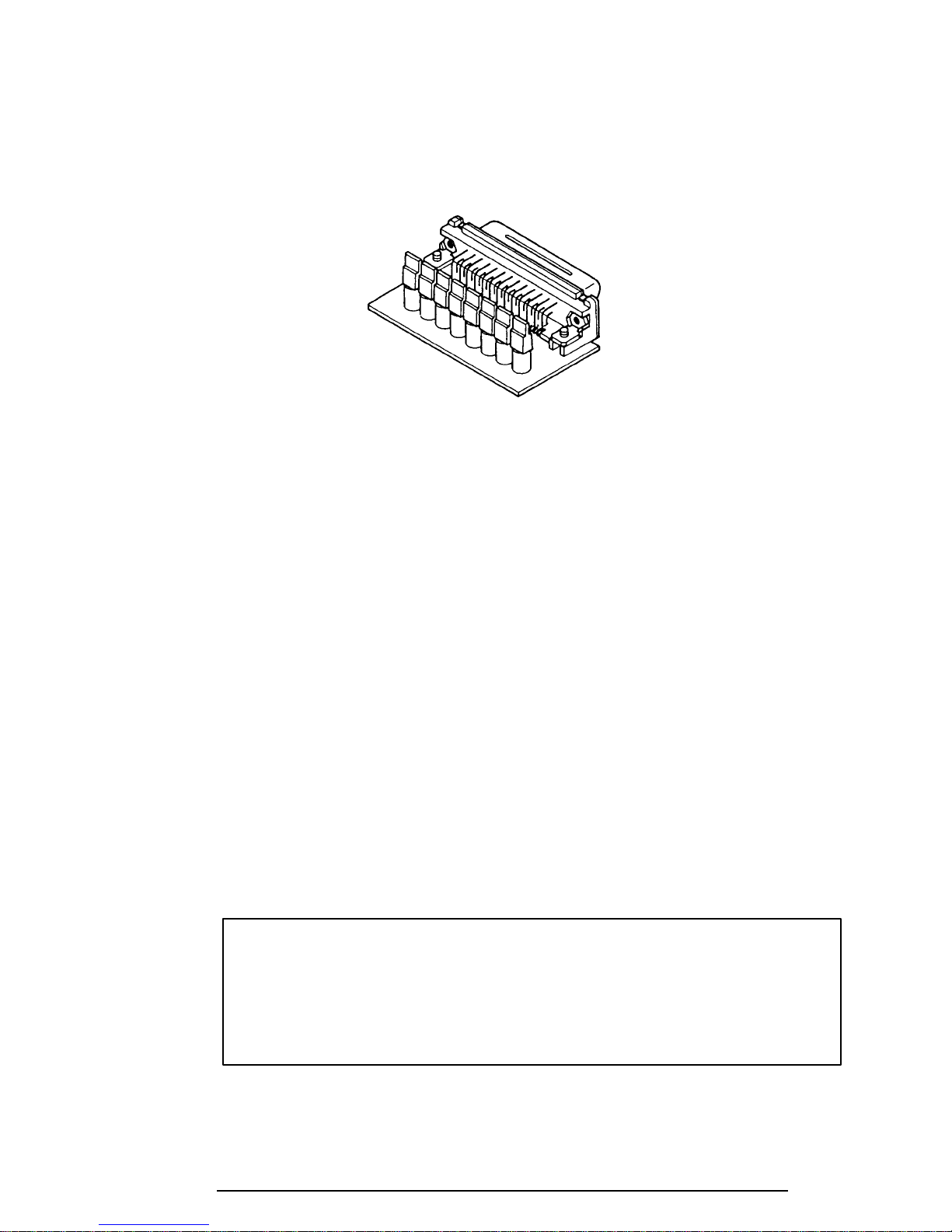
Procedure 2 Printer Port LED Check on Boot Mode
The printer port LED displays the IRT status and test status by turning lights on and off as an
eight-digit binary value for boot mode. Figure 2-2 shows the printer port LED.
Figure 2-2 Printer port LED
To use the printer port LED follow these steps:
1. Turn the computer's power on, then set to boot mode.
2. Turn the computer’s power off.
3. Plug the printer port LED into the parallel port.
4. Hold down the space bar and turn on the computer’s power.
5. Read the LED status from left to right as you are facing the back of the computer.
6. Convert the status from binary to hexadecimal notation.
7. If the final LED status is FFh (normal status), go to Procedure 3.
8. If the final LED status matches any of the test status values in table 2-1, perform
Check 1.
NOTE: If an error condition is detected by the IRT test, the printer port
LED displays an error code after the IRT test ends. For example, when the
printer port LED displays 1F and halts, the IRT test has already completed
the Display initialization. In this instance, the IRT indicates an error has
been detected during the system memory test.
400 Series
Page 32
2-12
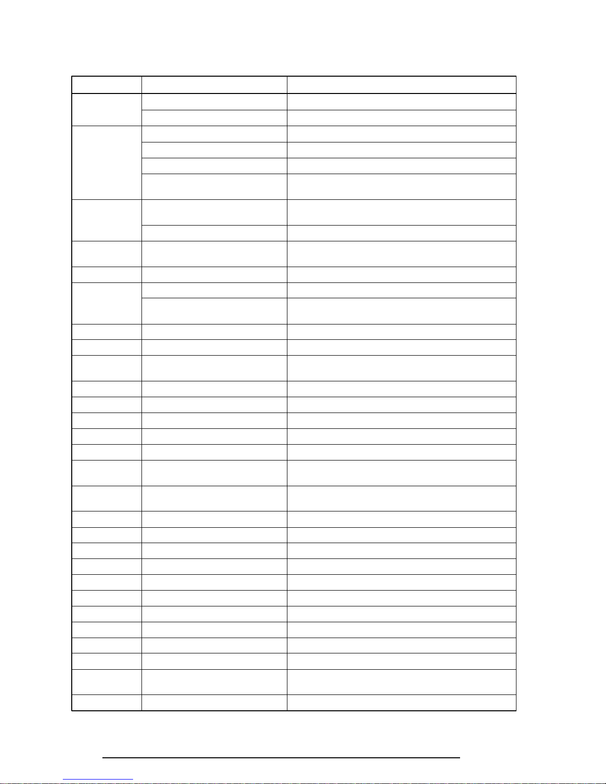
Table 2-1 Printer port LED boot mode status (1/2)
LED status Test item Message
01H KBC initialization
ROM checksum test BIOS is damaged! .....
02H Special register initialization
PIT test PIT ERROR
PIT initialization —
PIT function check MEMORY REFRESH ERROR
03H CMOS check CMOS CHECKSUM ERROR
KB initialization KBC ERROR
04H Initialization of —
memory configuration
05H SM-RAM check —
06H Self test check —
Read of Power Supply —
information
07H ROM/RAM copy —
08H Initialization of internal VGA —
0AH First 64 KB memory test FIRST 64KB MEMORY ERROR
0BH System memory initialization —
0CH System initialization —
0DH Interrupt vector initialization —
18H PIC initialization —
1FH Display initialization VRAM ERROR
25H System memory test SYSTEM MEMORY ERROR
30H Extended memory test EXTENDED MEMORY ERROR
40H DMA page register test DMA PAGE REGISTER ERROR
41H DMAC test DMAC #X ERROR
42H DMAC initialization —
4AH PIC test PIC #X ERROR
50H Mouse initialization —
55H KBC initialization KBC ERROR
60H HDD initialization HDC ERROR/HDD #0 ERROR
65H FDD initialization FDC ERROR/NO FDD ERROR
70H Printer initialization —
80H SIO initialization —
90H Timer initialization RTC UPDATE ERROR
A0H NDP initialization —
TIMER CH.2 OUT ERROR
CMOS BAD BATTERY ERROR
FIRST 64KB MEMORY PARITY ERROR
SYSTEM MEMORY PARITY ERROR
EXTENDED MEMORY PARITY ERROR
TIMER INTERRUPT ERROR
400 Series
Page 33

2-13
Table 2-1 Printer port LED boot mode status (2/2)
LED status Test item Message
A6H Initialization of expansion ROM —
C0H Password check —
FFH Setup boot check *** Bad xxxx xxxx ***
Check system. Then press [F1] key.
FFH Boot load —
Check 1 If the following error codes are displayed, go to Procedure 5.
00h, 01h, 02h, 03h, 04h, 05h, 06h, 07h, 0Ah, 0Bh, 0Ch, 0Dh, 18h, 1Fh, 25h,
30h, 40h, 41h, 42h, 4Ah, 65h, 70h, 80h, 90h, A0h, C0h, FFh
Check 2 If error code 50h is displayed, go to the Keyboard Troubleshooting procedures in
Section 2.7.
Check 3 If error code 55h is displayed, go to the HDD Troubleshooting Procedures in
Section 2.6.
Check 4 If error code 60h is displayed, go to the FDD Troubleshooting Procedures in
Section 2.5.
400 Series
Page 34
2-14
Procedure 3 Printer Port LED Check on Resume Mode
The printer port LED displays the IRT status and test status by turning lights on and off as an
eight-digit binary value for resume mode.
To use the printer port LED follow these steps:
1. Turn the computer’s power on, then set to resume mode.
2. Turn the computer’s power off.
3. Plug the printer port LED into the 400 series parallel port.
4. Turn the computer’s power on.
5. Read the LED status from left to right as you face the back of the computer.
6. Convert the status from binary to hexadecimal notation.
7. If the final LED status is FFh (normal status), go to Procedure 4.
8. If the final LED status matches any of the test status values in table 2-2, perform
Procedure 5.
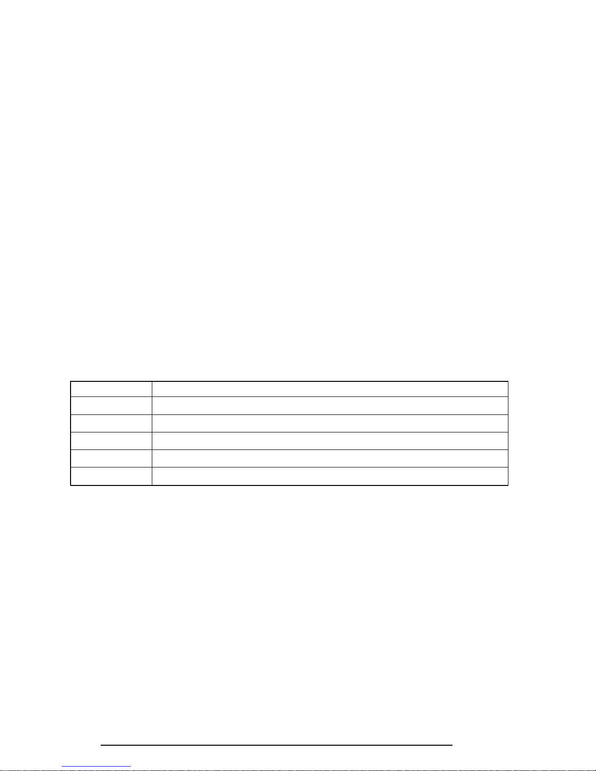
Table 2-2 Printer port LED resume mode error status
Error status Meaning of status
F1H RAM BIOS error
F2H The system has optional ROM, or optional card (CGA, MDA)
F5H Main memory checksum error
F6H Video RAM checksum error
F7H Extended memory checksum error
Procedure 4 Diagnostic Test Program Execution Check
Execute the following tests from the Diagnostic Test Menu. Refer to chapter 3, Tests and
Diagnostics, for more information on how to perform these tests.
1. System test
2. Memory test
3. Printer test
4. ASYNC test
5. Real Timer test
6. PCMCIA test
7. SOUND test
8. CD-ROM test
If an error is detected during these tests, go to Procedure 5.
400 Series
Page 35
2-15
Procedure 5 Replacement Check
The system board or the sound board may be damaged. Disassemble the 400 series following
the steps described in chapter 4, Replacement Procedures, and perform the following checks:
Check 1. Replace the system board with a new one. Refer to chapter 4 for instructions on
how to remove and replace the system board.
Check 2. Replace the sound board with a new one. Refer to chapter 4 for instructions on
how to remove and replace the sound board.
400 Series
Page 36

2-16
2.5 Floppy Disk Drive Troubleshooting
This section describes how to determine if the 400 series external 3.5-inch floppy disk drive is
functioning properly. Perform the steps below starting with Procedure 1 and continuing with
the other procedures as required.
Procedure 1: FDD Head Cleaning Check
Procedure 2: Diagnostic Test Program Execution Check
Procedure 3: Connector Check and Replacement Check
Procedure 1 FDD Head Cleaning Check
FDD head cleaning is one option available in the Diagnostic Program. Detailed operation is
given in chapter 3, Tests and Diagnostics.
After Toshiba MS-DOS loads, run the Diagnostic Program and then clean the FDD heads
using the cleaning kit. If the FDD still does not function properly after cleaning, go to Procedure 3.
If the test program cannot be executed on the 400 series, go to Procedure 3.
400 Series
Page 37

2-17
Procedure 2 Diagnostic Test Program Execution Check
The Floppy Disk Drive Diagnostic Test program is stored on the 400 series Diagnostics Disk.
After loading Toshiba MS-DOS, run the diagnostic program. Refer to Chapter 3, Tests and
Diagnostics, for more information about the diagnostics test procedures.
Floppy disk drive test error codes and their status names are described in table 2-3. Make
sure the floppy disk in the FDD is formatted correctly and that the write protect tab is disabled. If any other errors occur while executing the FDD diagnostics test, go to Check 1.
Table 2-3 Floppy disk drive error code and status
Code Status
01h Bad command
02h Address mark not found
03h Write protected
04h Record not found
06h Media removed on dual attach card
08h DMA overrun error
09h DMA boundary error
10h CRC error
20h FDC error
40h Seek error
60h FDD not drive
80h Time out error (Not ready)
EEh Write buffer error
FFh Data compare error
Check 1 If the following message is displayed, disable the write protect tab on the floppy
disk. If any other message appears, perform Check 2.
Write protected
Check 2 Make sure the floppy disk is formatted correctly. If it is, go to Procedure 3.
400 Series
Page 38
2-18
Procedure 3 Connector Check and Replacement Check
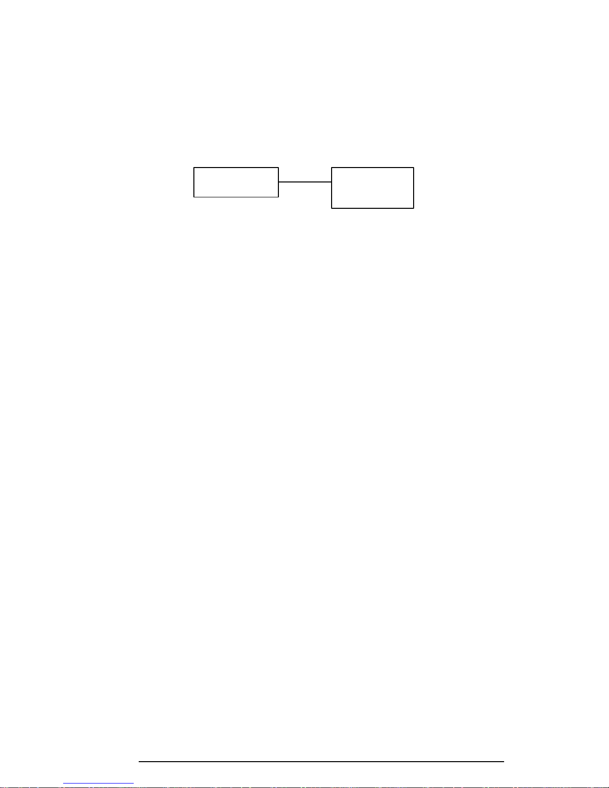
The 3.5-inch Floppy Disk Drive is connected to the external 3.5-inch FDD port by the FDD
cable. This cable may be damaged or disconnected from the external 3.5-inch FDD port.
Perform the following checks:
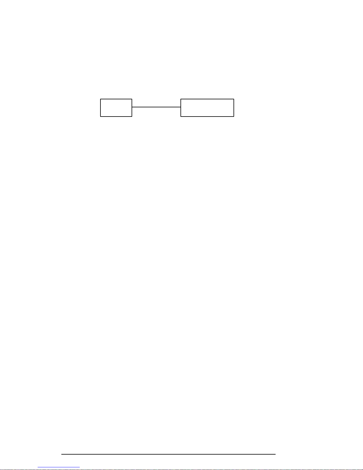
Check 1 Make sure the FDD cable is firmly connected to the external 3.5-inch FDD port.
FDD 400 system
If this cable is disconnected, connect it to the system unit and repeat Procedure 2.
If the FDD is still not functioning properly, perform Check 2.
Check 2 The cable may be defective or damaged. Replace the cable. If the FDD is still not
functioning properly, perform Check 3.
Check 3 The FDD or its cable may be defective or damaged. Replace the FDD with a new
one following the steps in chapter 4, Replacement Procedures. If the FDD is still
not functioning properly, perform Check 4.
Check 4 Replace the system board with a new one following the steps in chapter 4.
400 Series
Page 39

2-19
2.6 Hard Disk Drive Troubleshooting
To determine if the hard disk drive is functioning properly, perform the procedures below
starting with Procedure 1. Continue with the other procedures as instructed.
Procedure 1: Partition Check
Procedure 2: Message Check
Procedure 3: Format Check
Procedure 4: Diagnostic Test Program Execution Check
NOTE: The contents of the hard disk will be erased when the HDD troubleshooting
procedures are executed. Transfer the contents of the hard disk to a floppy disk(s) using
the BACKUP command in the Toshiba companion utility. Refer to the 400 series User’s
Manual for more information about how to perform the BACKUP.
Procedure 1 Partition Check
Insert the Toshiba MS-DOS system disk and turn on the computer. Then perform the following checks:
Check 1 Type C: and press Enter. If you cannot change to drive C, go to Check 2. If you
can change to drive C, go to Procedure 2.
Check 2 Type FDISK and press Enter. Choose Display Partition Information from the
FDISK menu. If drive C is listed, go to Check 3. If drive C is not listed, return to
the FDISK menu and choose the option to create a DOS partition on drive C.
Recheck the system. If the problem still exists, go to Procedure 2.
Check 3 If drive C is listed as active in the FDISK menu, go to Check 4. If drive C is not
listed as active, return to the FDISK menu and choose the option to set the active
partition for drive C. Recheck the system. If the problem still exists, go to Procedure 2.
Check 4 Remove the system disk from the FDD and cold boot the computer. If the prob-
lem still exists, go to Procedure 2. Otherwise, the HDD is operating normally.
400 Series
Page 40

2-20
Procedure 2 Message Check
When the 400 series HDD does not function properly, some of the following error messages
may appear on the display. Start with Check 1 below and perform the other checks as instructed.
Check 1 If any of the following messages appear, perform Check 2. If the following mes-
sages do not appear, perform Check 4:
HDC ERROR
(After 5 seconds this message will disappear)
or
HDD #0 ERROR
(After 5 seconds this message will disappear)
or
HDD #1 ERROR
(After 5 seconds this message will disappear)
Check 2 If either of the following messages appears, perform Procedure 3. If the following
messages do not appear, perform Check 3.
Insert system disk in drive
Press any key when ready .....
or
Non-System disk or disk error
Replace and press any key
Check 3 Using the Toshiba MS-DOS system disk, install a system program on the hard disk
using the SYS command.
If the following message appears on the display, the system program has been
transferred to the HDD. Restart the 400 series. If the error message still appears,
perform Check 4.
System transferred
Check 4 The HDD is connected to the system board directly. This connection can become
disconnected or damaged. Disassemble the 400 series as described in chapter 4,
Replacement Procedures. If the HDD is not connected, connect it to the system
board and return to Procedure 1. If the HDD is firmly connected to the system
board, perform Procedure 3.
System Board HDD
400 Series
Page 41

2-21
Procedure 3 Format Check
The 400 series HDD is formatted using the low level format program and the MS-DOS
FORMAT program. To format the HDD, start with Check 1 below and perform the other
steps as required.
Check 1 Using the Toshiba MS-DOS system disk, partition the hard disk using the FDISK
command. Format the hard disk using FORMAT C:/S/U to transfer the system
program to the HDD. If the following message appears on the display, the HDD
is formatted.
Format complete
If any other error message appears on the display, refer to the Toshiba MS-DOS
Manual for more information and perform Check 2.
Check 2 Using the 400 series Diagnostic Disk, format the HDD with a low level format
option. Refer to Chapter 3, Tests and Diagnostics for more information about the
diagnostic program.
If the following message appears on the display, the HDD low level format is
complete. Partition and format the HDD using the MS-DOS FORMAT command.
Format complete
If you cannot format the HDD using the Test and Diagnostic program, go to
Procedure 4.
400 Series
Page 42
2-22
Procedure 4 Diagnostic Test Program Execution Check
The HDD test program is stored in the 400 series Diagnostics Disk. Perform all of the HDD
tests in the Hard Disk Drive Test. Refer to chapter 3, Tests and Diagnostics, for more information about the HDD test program.
If an error is detected during the HDD test, an error code and status will be displayed; perform Check 1. The error codes and statuses are described in table 2-4. If an error code is not
generated, the HDD is operating properly.
Table 2-4 Hard disk drive error code and status
Code Status
01h Bad command
02h Bad address mark
04h Record not found
05h HDC not reset
07h Drive not initialized
08 HDC overrun (DRQ)
09h DMA boundary error
0Ah Bad sector error
0Bh Bad track error
10h ECC error
11h ECC recover enabled
20h HDC error
40h Seek error
80h Time out error
AAh Drive not ready
BBh Undefined error
CCh Write fault
E0h Status error
EEh Access time out error
FFh Data compare error
Check 1 Replace the HDD unit with a new one following the instructions in chapter 4,
Replacement Procedures. If the HDD is still not functioning properly, perform
Check 2.
Check 2 Replace the system board with a new one following the instructions in chapter 4.
400 Series
Page 43
2-23
2.7 Keyboard Troubleshooting
To determine if the 400 series keyboard is functioning properly, perform the following procedures. Start with Procedure 1 and continue with the other procedures as instructed.
Procedure 1: Diagnostic Test Program Execution Check
Procedure 2: Connector and Replacement Check
Procedure 1 Diagnostic Test Program Execution Check
Execute the Keyboard Test in the Diagnostic Program. Refer to chapter 3, Tests and Diagnostics, for more information on how to perform the test program.
If an error occurs, go to Procedure 2. If an error does not occur, the keyboard is functioning
properly.
Procedure 2 Connector and Replacement Check
The keyboard is connected to the system board by a flat cable. This cable may be disconnected or damaged. Disassemble the 400 series as described in chapter 4, Replacement
Procedures, and perform the following checks:
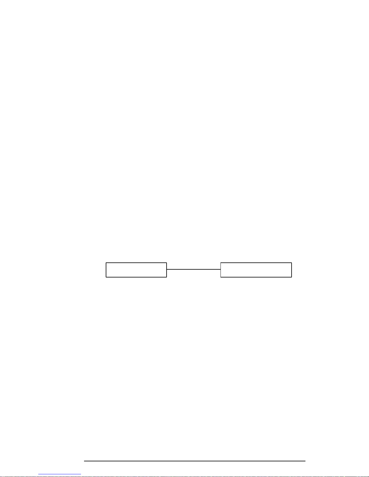
Check 1 Make sure the keyboard cable is not damaged and is connected to the system
board.
Keyboard cable PJ14 System board
If this cable is damaged, replace the keyboard with a new one. If the cable is
disconnected, firmly connect it. Perform Procedure 1 again. If the keyboard is
still not functioning properly, perform Check 2.
Check 2 The keyboard controller on the system board may be damaged. Replace the
system board with a new one. Refer to chapter 4 for more information.
400 Series
Page 44

2-24
2.8 Display and VGA Board Troubleshooting
This section describes how to determine if the 400 series display is functioning properly. Start
with Procedure 1 and continue with the other procedures as instructed.
Procedure 1: Contrast Control Check (400CS only)
Procedure 2: External CRT Check
Procedure 3: Diagnostic Test Program Execution Check
Procedure 4: Connector Check
Procedure 5: Replacement Check
Procedure 1 Contrast Control Check (400CS only)
Contrast is changed by the contrast dial. If the contrast does not change when you turn the
contrast dial, perform Procedure 2.
Procedure 2 External CRT Check
Connect the external CRT to the 400 series external monitor port, then boot the computer.
The computer automatically detects the external CRT even if Resume mode is enabled.
If the external CRT works correctly, the internal LCD display may be damaged. Go to Procedure 4.
If the external CRT appears to have the same problem as the internal LCD, the display controller may be damaged. Go to Procedure 3.
Procedure 3 Diagnostic Test Program Execution Check
The Display Test program is stored on the 400 series Diagnostic Disk. This program checks
the display controller on the system board. After loading Toshiba MS-DOS, run the Diagnostic Program. Refer to chapter 3, Tests and Diagnostics, for details.
If an error is detected, go to Procedure 4. If an error is not detected, the display is functioning properly.
400 Series
Page 45
2-25
Procedure 4 Connector Check
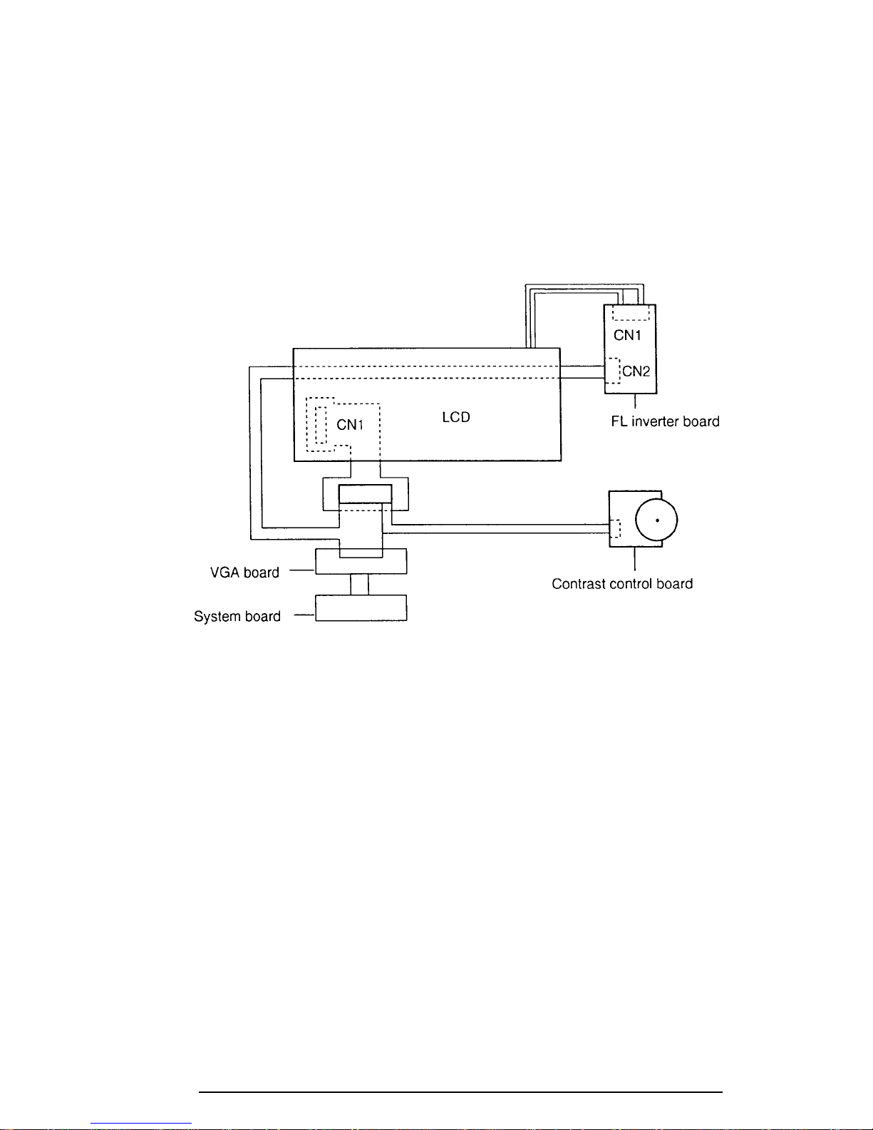
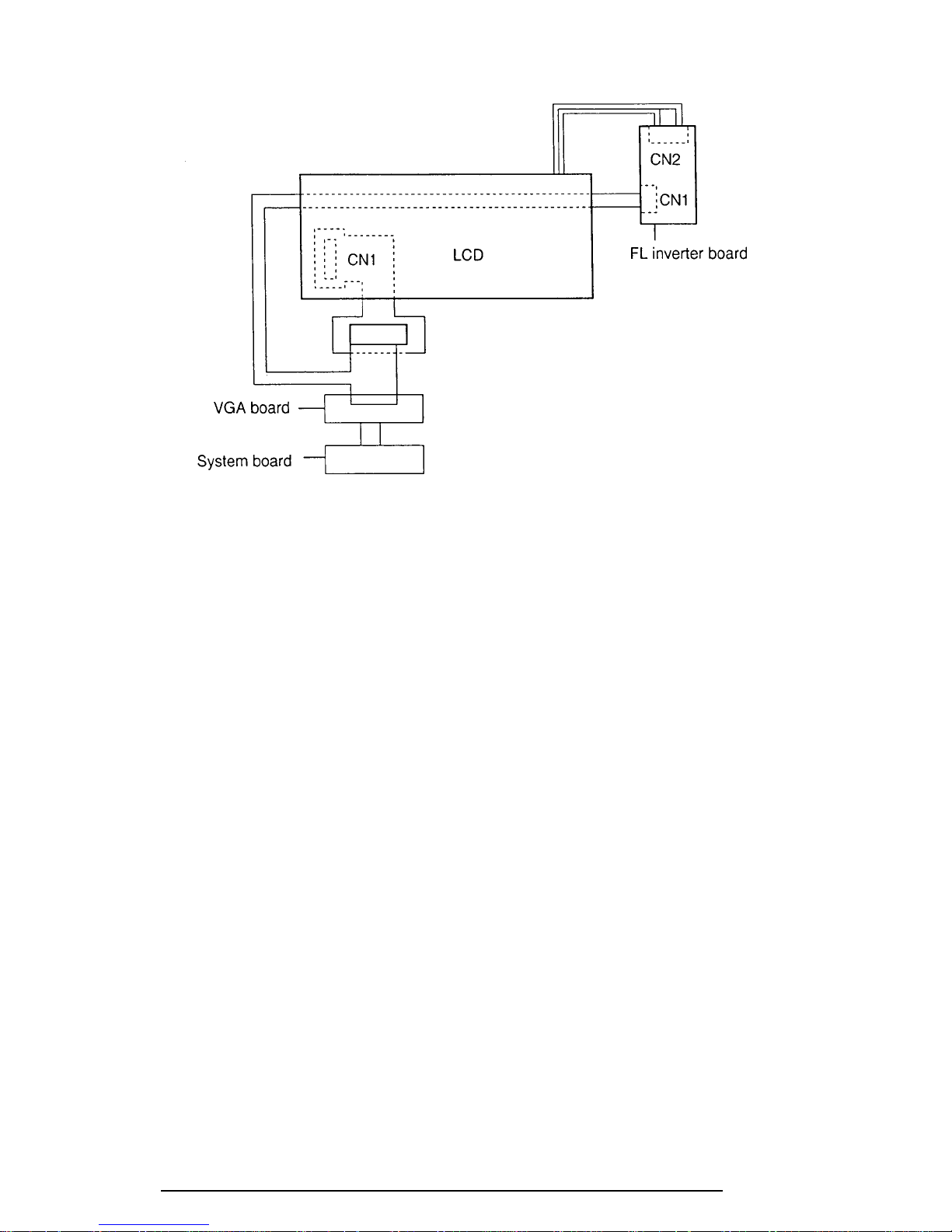
The Display unit has an LCD module, FL, Display switch, and FL inverter board. The FL
and FL inverter board are connected by two cables. The LCD module and system board are
connected by two signal (400CDT) cables as shown below. Any of these cables may be
disconnected.
Disassemble the display unit and check the following cable connections. Refer to chapter 4.
Replacement Procedures, for more information about how to disassemble the computer.
Figure 2-3 400CS display connection
400 Series
Page 46
2-26
Figure 2-4 400CDT display connection
If any of these cables is not connected, firmly reconnect it and repeat Procedures 1 and 2. If
the problem still exists, perform Procedure 5.
400 Series
Page 47

2-27
Procedure 5 Replacement Check
The FL, FL inverter board, LCD module, and system board are connected to the display
circuits. Any of these components may be damaged. Refer to chapter 4, Replacement Proce-
dures, for instructions on how to disassemble the computer and then perform the following
checks:
If the FL does not light, perform Check 1.
If characters are not displayed clearly, perform Check 3.
If some screen functions do not operate properly, perform Check 3.
If the FL remains lit when the display is closed, perform Check 4.
Check 1 Replace the FL with a new one and test the display again. If the problem still
exists, perform Check 2.
Check 2 Replace the FL inverter board with a new one and test the display again. If the
problem still exists, perform Check 3.
Check 3 Replace the LCD module with a new one and test the display again. If the
problem still exists, perform Check 4.
Check 4 Replace the display switch with a new one and test the display again. If the
problem still exists, perform Check 5.
Check 5 Replace the display cable with a new one and test the display again. If the
problem still exists, perform Check 6.
Check 6 The system board may be damaged. Replace the system board with a new one.
400 Series
Page 48

2-28
2.9 CD-ROM Drive Troubleshooting
This section describes how to determine if the 400 series internal CD-ROM drive is functioning properly. Perform the steps below starting with Procedure 1 and continuing with the
other procedures as required.
Procedure 1: CD Cleaning Check
Procedure 2: Diagnostic Test Program Execution Check
Procedure 3: Connector Check and Replacement Check
Procedure 1 CD Cleaning Check
Clean the laser pickup lens with a lens cleaner. Apply the cleaner to a cloth and wipe the lens.
If the CD-ROM drive still does not function properly after cleaning, go to Procedure 2.
Procedure 2 Diagnostic Test Program Execution Check
The CD-ROM drive Diagnostic Test program is stored on the 400 series Diagnostics Disk.
After Toshiba MS-DOS loads, run the diagnostic program stored on the test program diskette. Insert a test CD (Toshiba-EMI Test Disc TDY-03) into the CD-ROM drive and run
the test. Refer to Chapter 3, Tests and Diagnostics, for more information about the diagnostics test procedures.
If any other errors occur while executing the CD-ROM drive diagnostics test, go to Procedure 3.
400 Series
Page 49
2-29
Procedure 3 Connector Check and Replacement Check
The CD-ROM drive is connected to the system board and sound board by the CD-ROM drive
cable. This cable may be disconnected from the system board or damaged. Disassemble the
400 series following the steps described in Chapter 4, Replacement Procedures, and perform
the following checks:
Check 1 Make sure the CD-ROM is firmly connected to the system board.
CD-ROM drive PJ5
System board
If this cable is disconnected, connect it to the system unit and repeat Procedure 2.
If the CD-ROM is still not functioning properly, perform Check 2.
Check 2 The CD-ROM drive may be defective or damaged. Replace the CD-ROM drive
with a new one following the steps in Chapter 4. If the CD-ROM drive is still not
functioning properly, perform Check 3.
Check 3 Replace the system board with a new one following the steps in chapter 4.
400 Series
Page 50

3-1
3.1 The Diagnostic Test
This chapter explains how to use the Diagnostic Test program to test the functions of the
computer’s hardware modules. The Diagnostics Program is stored on the Diagnostic Disk.
The Diagnostic Test consists of 8 programs that are grouped into the Service Program Module (DIAGNOSTIC TEST MENU) and the Test Program Module (DIAGNOSTIC TEST).
NOTES: To start the diagnostics, follow these steps:
1. Check all cables for loose connections.
2. Exit any application you may be using and close Windows.
3. Be sure the computer is not in virtual 86 mode The test will not run in that mode.
If you try to run the test in virtual 86 mode, the following message will be displayed:
Cannot execute in a virtual 8086 mode.
If the preceding message is displayed, remove memory managers from your
config.sys file. See your MS-DOS documentation for information on the config.sys
file.
4. Go to drive C and at the DOS prompt C:\>, type TDIAGS. MS-DOS loads the
diagnostic test and displays the following screen:
TOSHIBA personal computer xxxx DIAGNOSTICS
version x.xx (c) copyright TOSHIBA Corp. 19xx
Test the DIAGNOSTICS (Y/N)
5. To execute the program type Y; to exit, type N.
The DIAGNOSTIC MENU consists of the following eight functions. These are all located
within the Diagnostic test function of the DIAGNOSTIC TEST MENU.
❑ DIAGNOSTIC TEST
❑ HARD DISK FORMAT
❑ HEAD CLEANING
❑ LOG UTILITIES
❑ RUNNING TEST
❑ FDD UTILITIES
❑ SYSTEM CONFIGURATION
❑ SETUP
400 Series
Page 51

3-2
The DIAGNOSTIC TEST MENU contains the following 13 functional tests:
❑ SYSTEM TEST
❑ MEMORY TEST
❑ KEYBOARD TEST
❑ DISPLAY TEST
❑ FLOPPY DISK TEST
❑ PRINTER TEST
❑ ASYNC TEST
❑ HARD DISK TEST
❑ REAL TIMER TEST
❑ NDP TEST
❑ EXPANSION TEST
❑ SOUND TEST
❑ CD-ROM TEST
You will need the following equipment to perform some of the 400 series Diagnostic test
programs.
❑ The 400 series Diagnostics Disk (all tests)
❑ A formatted working disk for the floppy disk drive test (all tests)
❑ 3.5-inch 2HD/2DD disk for external 3.5-inch FDD
❑ A cleaning kit to clean the floppy disk drive heads (Head Cleaning)
❑ A PCMCIA wraparound connector for the I/O card test (PCMCIA test)
❑ A printer wraparound connector for the printer wraparound test (Printer test)
❑ An RS-232-C wraparound connector for the RS-232-C port wraparound test
(ASYNC test)
❑ A CD test media
❑ The port replicator
The following sections detail the tests within the Diagnostic Test function of the DIAGNOSTIC TEST MENU. Refer to Sections 3.19 through 3.25 for detailed information on the
remaining seven Service Program Module functions.
400 Series
Page 52
3-3
3.2 Executing the Diagnostic Test
Toshiba MS-DOS is required to run the DIAGNOSTICS PROGRAM. To start the DIAGNOSTIC PROGRAM follow these steps:
1. Insert the Diagnostics disk in the computer’s floppy disk drive and turn on the
computer.
2. At the system prompt, change to drive A and type the test command or
CDROMDRV (CD-ROM test only), then press Enter.
The following menu will appear:
TOSHIBA personal computer xxx DIAGNOSTICS
version X.XX (c) copyright TOSHIBA Corp. 19XX
DIAGNOSTICS MENU :
1 - DIAGNOSTIC TEST
2 - HARD DISK FORMAT
3 4 - HEAD CLEANING
5 - LOG UTILITIES
6 - RUNNING TEST
7 - FDD UTILITIES
8 - SYSTEM CONFIGURATION
9 - EXIT TO MS-DOS
0 - SETUP
↑↓→← : Select items
Enter : Specify
Esc : Exit
NOTE: To exit the 400 series DIAGNOSTIC TEST MENU, press the Esc
key. If a test program is in progress, press Ctrl + Break to exit the test
program or press Ctrl + C to stop the test program.
400 Series
Page 53

3-4
3. To execute the DIAGNOSTIC TEST MENU from the DIAGNOSTICS MENU,
set the highlight bar to 1, and press Enter. The following DIAGNOSTIC TEST
MENU will appear:
TOSHIBA personal computer xxx DIAGNOSTICS
version X.XX (c) copyright TOSHIBA Corp. 19XX
DIAGNOSTIC TEST MENU :
1 - SYSTEM TEST
2 - MEMORY TEST
3 - KEYBOARD TEST
4 - DISPLAY TEST
5 - FLOPPY DISK TEST
6 - PRINTER TEST
7 - ASYNC TEST
8 - HARD DISK TEST
9 - REAL TIMER TEST
10 - NDP TEST
11 - EXPANSION TEST
12 - SOUND TEST
13 - CD-ROM TEST
88 - ERROR RETRY COUNT SET [HDD & FDD]
99 - EXIT TO DIAGNOSTICS MENU
↑↓→← : Select items
Enter : Specify
Esc : Exit
Refer to sections 3.4 through 3.16 for detailed descriptions of Diagnostic Tests 1
through 12. Function 88 sets the floppy disk drive and hard disk drive error retry
count. Function 99 exits the submenus of the Diagnostic Test and returns to the
Diagnostic Menu.
4. Select the option you want to execute and press Enter. The following message
will appear:
SYSTEM TEST XXXXXXX
xxx DIAGNOSTIC TEST VX.XX
[Ctrl]+[Break]; test end
[Ctrl]+[C] ; key stop
SUB-TEST : XX
PASS COUNT: XXXXX ERROR COUNT: XXXXX
WRITE DATA: XX READ DATA : XX
ADDRESS : XXXXXX STATUS : XXX
SUB-TEST MENU :
01 - ROM checksum
02 03 04 - Fan ON/OFF
05 - Termister check
99 - Exit to DIAGNOSTIC TEST MENU
↑↓→← : Select items
Enter : Specify
Esc : Exit
NOTE: The menu displayed by your 400 series may be slightly different from
the one shown above.
400 Series
Page 54

3-5
5. Select the desired subtest number from the subtest menu and press Enter.
The following message will appear:
TEST LOOP : YES
Selecting YES increases the pass counter by one each time the test cycle ends,
then restarts the test cycle.
Selecting NO returns the subtest menu to the main menu after the test is complete.
6. The following message will appear:
ERROR STOP : YES
Use the left or right arrow keys to move the cursor to the desired option and press
Enter.
Selecting YES stops the test program when an error is found and displays the
operation guide on the right side of the display screen as shown below:
ERROR STATUS NAME [[ HALT OPERATION ]]
1: Test end
2: Continue
3: Retry
These three selections function as follows:
1: Terminates the test program and exits to the subtest menu.
2: Continues the test.
3: Restarts the test from the error.
Selecting NO keeps the test running even if an error is found.
7. Use the arrow keys to move the cursor to the desired option and press Enter.
Table 3-1 in section 3.3 describes the function of each test on the subtest menu.
Table 3-3 in section 3.17 describes the error codes and error status for each error.
400 Series
Page 55
3-6
3.3 Subtest Names
Table 3-1 lists the subtest names for each test program in the DIAGNOSTIC TEST MENU.
Table 3-1 Subtest names (1/2)
No. Test name Subtest No. Subtest item
1 SYSTEM 01 ROM checksum
04 Fan ON/OFF
05 Thermistor check
2 MEMORY 01 Constant data
02 Address pattern data
03 Refresh
04 Protected mode
05 Memory module
06 Cache memory
3 KEYBOARD 01 Pressed key display
02 Pressed keycode display
03 PS/2 Mouse connect check
04 Pointing stick
4 DISPLAY 01 VRAM read/write
02 Character attributes
03 Character set
04 80x25/30 Character display
05 320x200 Graphics display
06 640x200 Graphics display
07 640x350/480 Graphics display
08 Display page
09 “H” pattern display/Border color
10 LED/DAC pallet
11 TFT color display (400CDT only)
5 FDD 01 Sequential read
02 Sequential read/write
03 Random address/data
04 Write specified address
05 Read specified address
6 PRINTER 01 Ripple pattern
02 Function
03 Wraparound
400 Series
Page 56
3-7
Table 3-1 Subtest names (2/2)
No. Test name Subtest No. Subtest item
7 ASYNC 01 Wraparound (board)
02 Board (#1) <=> board (#2)
03 Point to point (send)
04 Point to point (receive)
05 Interrupt test
06 Infra_red Wrap_around test
07 Infra_red Transmit mode
08 Infra_red Receive mode
8 HDD 01 Sequential read
02 Address uniqueness
03 Random address/data
04 Cross talk & peak shift
05 Write/read/compare (CE)
06 Write specified address
07 Read specified address
08 ECC circuit
09 Sequential write
10 W-R-C specified address
9 REAL TIMER 01 Real time
02 Backup memory
03 Real time carry
10 NDP 01 NDP test
11 EXPANSION 01 PCMCIA wrap around (Internal)
02 PCMCIA wrap around (External)
12 SOUND 01 CODEC (Recoding/Playback)
02 FM-Synthesizer
03 SINE-Wave Playback
04 Joystick
05 MIDI wraparound
06 CODEC (Line In/Out)
13 CD-ROM 01 Sequential read
02 Read specified address
03 Random address/data
04 Playback Music
400 Series
Page 57

3-8
3.4 System Test
To execute the System Test select 1 from the DIAGNOSTIC TEST MENU, press Enter and
follow the directions displayed on the screen. Move the highlight bar to the subtest you want
to execute and press Enter.
Subtest 01 ROM checksum
The ROM checksum tests the system board from address F0000h to FFFFFh
(64KB).
Subtest 02 Not used
Subtest 03 Not used
Subtest 04 Fan on/off
This subtest checks fan operation.
The fan cable is securely connected to PJ11 on the system board. When you
execute this subtest, the following message is displayed:
*** Fan ON *** : Press [Enter] key?
When you press Enter, the fan should spin.
*** Fan OFF *** : Press [Enter] key?
When you press Enter, the fan should stop.
Subtest 05 Thermistor check
This subtest checks the thermistor that controls CPU temperature. The thermistor cable connects to PJ23 on the system board.
400 Series
Page 58
3-9
3.5 Memory Test
To execute the Memory Test, select 2 from the DIAGNOSTIC TEST MENU, press Enter
and follow the directions displayed on the screen. Move the highlight bar to the subtest you
want to execute and press Enter.
Subtest 01 Constant data (real mode)
This subtest writes a 256-byte unit of constant data to conventional memory (0
to 640 KB). Then reads the new data and compares the result with the original
data. The constant data is FFFFh, AAAAh, 5555h, and 0000h.
Subtest 02 Address pattern data (real mode)
This subtest writes address pattern data created by the exclusive-ORing
(XORing), to the address segment and address offset in conventional memory
program end to 640 KB), then reads the new data and compares the result with
the original data.
Subtest 03 Refresh (real mode)
This subtest writes a 256-byte unit of constant data to conventional memory (0
to 640 KB) then reads the new data and compares the result with the original
data.
The constant data is AAAAh and 5555h.
NOTE: There is a short delay between write and read operations,
depending on the size of the data.
Subtest 04 Protected mode
NOTE: The CONFIG.SYS file must be configured without expanded
memory manager programs such as EMM386.EXE, EMM386.SYS or
QEMM386.SYS. Also, the HIMEM.SYS must be deleted from the
CONFIG.SYS file
This subtest writes constant data and address data to extended memory (maximum address 100000h) then reads new data and compares the result with the
original data.
The constant data is FFh, AAh, 55h, and 00h.
400 Series
Page 59

3-10
Subtest 05 Memory module
NOTE: To execute this subtest, an optional memory card must be
installed in the computer.
This subtest functions the same as subtest 04, except it is used for testing an
optional memory card. Memory module capacity is 8 MB, 16 MB, and 32
MB.
After selecting subtest 05, the following message will appear:
Extended memory size (2:8 MB,3:16 MB,4:32 MB)?
Select the number that corresponds to the memory card installed in the 400
series.
Subtest 06 Cache memory
To test the cache memory, a pass-through write-read comparison of ‘5A’ data
is run repeatedly to test area (‘7000’:’Program’ size to ‘7000’:=7FFF’ (32
KB)) to check the hit-miss ratio (on/off status). One test takes 3 seconds.
Number of misses < Number of hits → OK
Number of misses ≥ Number of hits → Fail
400 Series
Page 60
3-11
3.6 Keyboard Test
To execute the Keyboard Test, select 3 from the DIAGNOSTIC TEST MENU, press Enter
and follow the directions displayed on the screen. The Keyboard test contains four subtests
that test the 400 series keyboard actions. Move the highlight bar to the subtest you want to
execute and press Enter.
Subtest 01 Pressed key display (82/84)
NOTE: The Num Lock and the Overlay mode must be off to execute
this subtest.
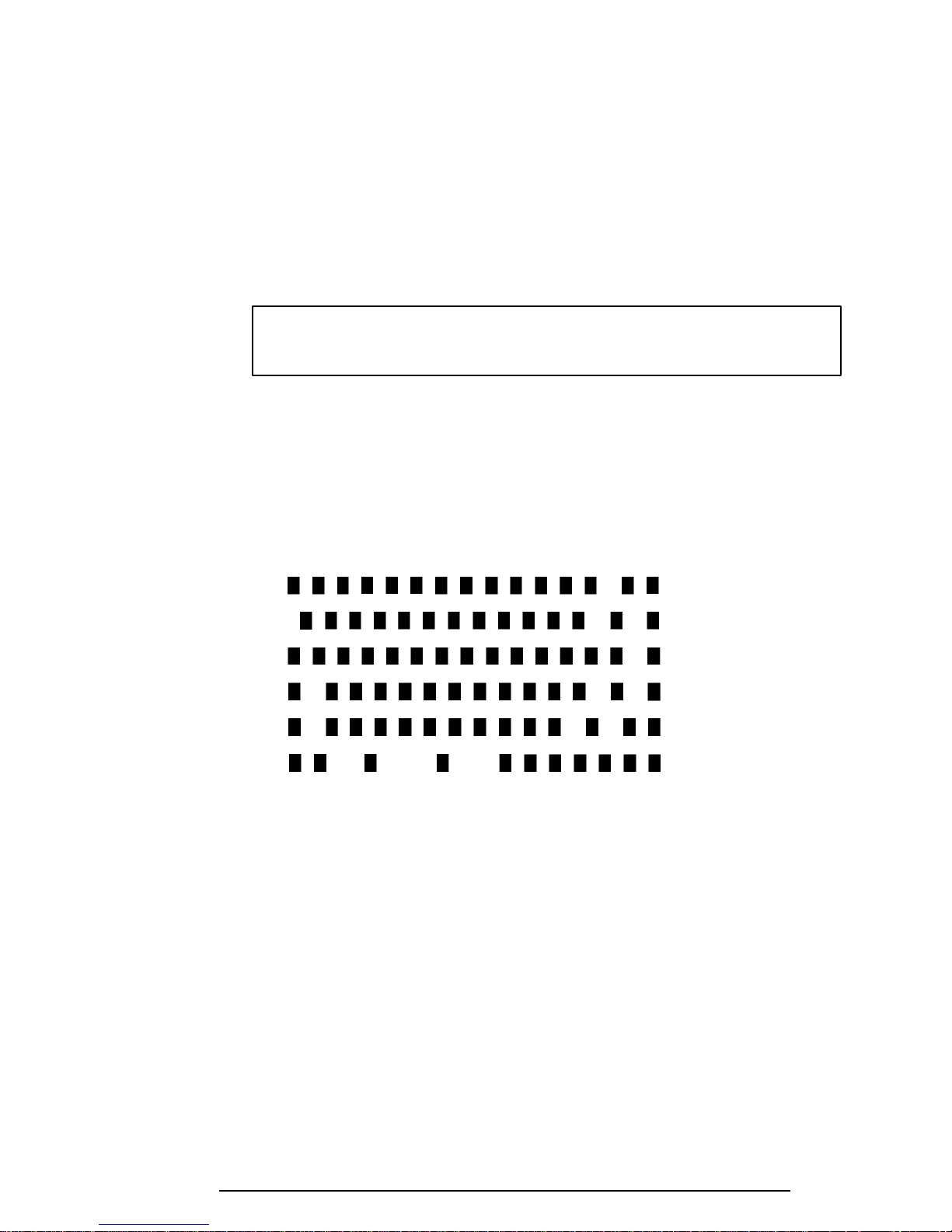
When you execute this subtest, the keyboard layout is drawn on the display as
shown below. When any key is pressed, the corresponding key on the screen
changes to an “*” character. Holding a key down enables the auto-repeat
function which causes the key’s display character to blink.
[[[ Press Key Display ]]]
If test OK, Press [Del] [Enter] Key
400 Series
Page 61
3-12
Subtest 02 Pressed key code display
When a key is pressed, the scan code, character code, and keytop name are
displayed on the screen in the format shown below. The Ins, Caps Lock,
Num Lock, Scroll Lock, Alt, Ctrl, Left Shift, and Right Shift keys are
displayed in reverse screen mode when pressed. The scan codes, character
codes, and keytop names are shown in Appendix D.
KEYBOARD TEST IN PROGRESS 302000
Scan code =
Character code =
Keytop =
Ins Lock Caps Lock Num Lock Scroll Lock
Alt Ctrl Left Shift Right Shift
PRESS [Enter] KEY
Subtest 03 PS/2 mouse connect check
NOTE: To execute the PS/2 mouse connect check, a PS/2 mouse must be
connected to the port replicater.
This subtest checks whether a PS/2 mouse is connected.
If this test does not detect an error, it returns to the subtest menu.
If this test detects an error, the following message appears:
KBD - MOUSE INTERFACE ERROR
[[ HALT OPERATION ]]
1: Test end
2: Continue
3: Retry
400 Series
Page 62
3-13
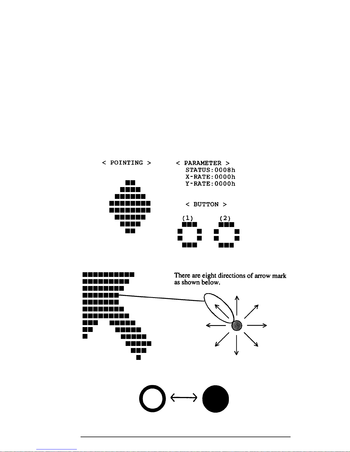
Subtest 04 Pointing Stick
This subtest checks the functions of the pointing stick as shown below.
a) IPS stick pressure sensing direction and parameter.
b) IPS switch function check.
This test reports the pointing stick motion response from the IPS and IPS
switch by displaying the location parameters. When the stick is pressed towards the upper left, the <POINTING> display changes according to the
following illustration. If an IPS switch is pressed, the <BUTTON> display
alternates between black and white. Also, the parameters appear on the right
side of the display. If two IPS switches are pressed at the same time, the
subtest menu is displayed.
***** IPS TEST PROGRAM (V1.00) *****
<< PRESS BUTTON1 + BUTTON2 THEN END >>
When a button is pressed, the display alternates as shown below.
400 Series
Page 63

3-14
3.7 Display Test
To execute the Display Test, select 4 from the DIAGNOSTIC TEST MENU, press Enter and
follow the directions displayed on the screen. The Display test contains ten subtests (for the
400CS, plus one more for the 400CDT) that test the 400 series display in various modes.
Move the highlight bar to the subtest you want to execute and press Enter.
Subtest 01 VRAM Read/Write
This subtest writes constant data FFFFh, AAAAh, 5555h, 0000h and address
data to video RAM (1MB). This data is then read from the video RAM and
compared to the original data.
Subtest 02 Character Attributes (mode 1, 13h)
This subtest displays the following character attribute modes; normal, intensified, reverse, and blinking as shown in the display below. The character
attribute modes display the foreground color and intensified color (16 colors or
16-level gray scale) using black, blue, red, magenta, green, cyan, yellow, and
white from the color display. The display below appears on the screen when
this subtest is executed.
CHARACTER ATTRIBUTES
NEXT LINE SHOWS NORMAL DISPLAY.
NNNNNNNNNNNNNNNNNNNNNNNNNNNNNN
NEXT LINE SHOWS INTENSIFIED DISPLAY.
IIIIIIIIIIIIIIIIIIIIIIIIIIIIII
NEXT LINE SHOWS REVERSE DISPLAY.
RRRRRRRRRRRRRRRRRRRRRRRRRRRRRR
NEXT LINE SHOWS BLINKING DISPLAY.
BBBBBBBBBBBBBBBBBBBBBBBBBBBBBB
00 08 ; BLACK
01 09 ; BLUE
04 0C ; RED
05 0D ; MAGENTA
02 0A ; GREEN
03 0B ; CYAN
06 0E ; YELLOW
07 0F ; WHITE
PRESS [Enter] KEY
400 Series
Page 64
3-15
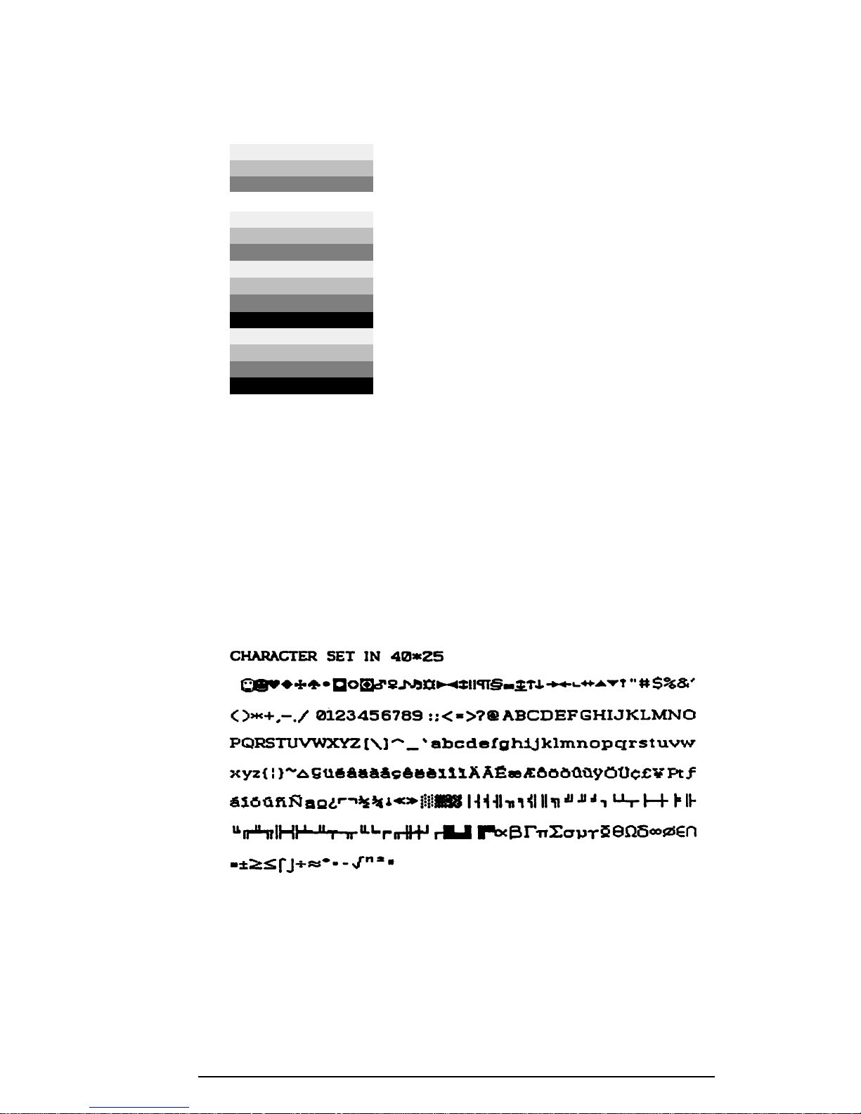
After pressing Enter, 16 colors or 16 gray scales of mode 13h appear in the
320x200 graphics mode as shown below:
BLACK
BLUE
GREEN
CYAN
RED
MAGENTA
BROWN
WHITE
GRAY
LIGHT BLUE
LIGHT GREEN
LIGHT CYAN
LIGHT RED
LIGHT MAGENTA
YELLOW
INTENSE WHITE
Pressing Enter toggles between the two tests.
To exit this subtest and return to the DISPLAY TEST menu, press Ctrl +
Break.
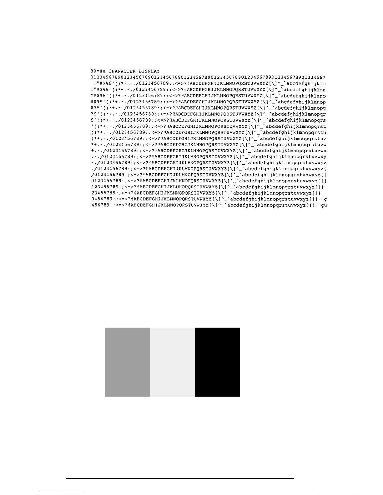
Subtest 03 Character Set
In this subtest, the character set (addressed 00h to FFh) is displayed in the
40*25 character mode as shown below.
Press [Enter] KEY
To exit this subtest and return to the DISPLAY TEST menu, press Ctrl +
Break.
400 Series
Page 65
3-16
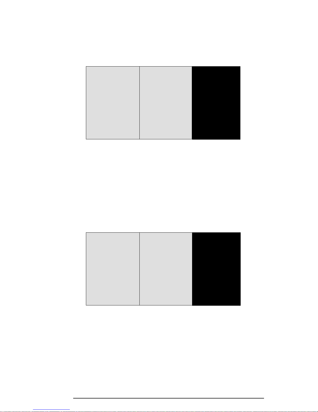
Subtest 04 80x25/30 Character Display (mode 3, 12)
In this subtest, the character string is displayed shifting one character to the
right, line by line in the 80x25 and 80x30 character modes as shown below.
Pressing Enter toggles between tests. To exit this subtest and return to the
DISPLAY TEST menu, press Ctrl + Break.
Subtest 05 320x200 Graphics Display (mode 4,D)
This subtest displays two color sets for the color display in 320x200 dot
graphics mode 4 and D. One example is shown below:
GREEN RED BROWN
CYAN MAGENTA WHITE
Pressing Enter toggles between tests. To exit this subtest and return to the
DISPLAY TEST menu, press Ctrl + Break.
400 Series
Page 66
3-17
Subtest 06 640x200 Graphics Display (mode 6, E)
This subtest displays even dots, odd dots, and all dots in the 640x200 dot
graphics mode 6 and E as shown below:
To exit this subtest and return to the DISPLAY TEST menu, press Ctrl +
Break.
Subtest 07 640x350/480 Graphics Display (mode 10, 74, 12)
This subtest displays even dots, odd dots, and all dots in the 640x350 and
640x480 dot graphics mode 10, 74, 12 as shown below:
Pressing Enter changes the size of the displayed image. To exit this subtest
and return to the DISPLAY TEST menu, press Ctrl + Break.
400 Series
Page 67

3-18
Subtest 08 Display Page
This subtest confirms that the pages can be changed in order from page 0
through page 7 in 40*25 character mode.
DISPLAY PAGE 0
0000000000000000000000000000000000000000
0 0
0 0
0 0
0 0
0 0
0 0
0 0
0 0
0 0
0 0
0000000000000000000000000000000000000000
Pressing Ctrl + Break exits this subtest, after completion of the test, and
returns to the DISPLAY TEST menu.
Subtest 09 H Pattern Display/Border Color
This subtest displays 2400 H characters on the entire screen, as shown below.
HHHHHHHHHHHHHHHHHHHHHHHHHHHHHHHHHHHHHHHHHHHHHHHHHH
HHHHHHHHHHHHHHHHHHHHHHHHHHHHHHHHHHHHHHHHHHHHHHHHHH
HHHHHHHHHHHHHHHHHHHHHHHHHHHHHHHHHHHHHHHHHHHHHHHHHH
HHHHHHHHHHHHHHHHHHHHHHHHHHHHHHHHHHHHHHHHHHHHHHHHHH
HHHHHHHHHHHHHHHHHHHHHHHHHHHHHHHHHHHHHHHHHHHHHHHHHH
HHHHHHHHHHHHHHHHHHHHHHHHHHHHHHHHHHHHHHHHHHHHHHHHHH
HHHHHHHHHHHHHHHHHHHHHHHHHHHHHHHHHHHHHHHHHHHHHHHHHH
HHHHHHHHHHHHHHHHHHHHHHHHHHHHHHHHHHHHHHHHHHHHHHHHHH
HHHHHHHHHHHHHHHHHHHHHHHHHHHHHHHHHHHHHHHHHHHHHHHHHH
HHHHHHHHHHHHHHHHHHHHHHHHHHHHHHHHHHHHHHHHHHHHHHHHHH
HHHHHHHHHHHHHHHHHHHHHHHHHHHHHHHHHHHHHHHHHHHHHHHHHH
HHHHHHHHHHHHHHHHHHHHHHHHHHHHHHHHHHHHHHHHHHHHHHHHHH
HHHHHHHHHHHHHHHHHHHHHHHHHHHHHHHHHHHHHHHHHHHHHHHHHH
HHHHHHHHHHHHHHHHHHHHHHHHHHHHHHHHHHHHHHHHHHHHHHHHHH
Pressing Enter displays the following message:
Setting the color CRT (1:yes/2:no) ?
If an external CRT display is connected to the 400 series, choose 1 to display
the following message:
[Border color test (7 times press [Enter] key]
Press Enter to execute the border color test.
To exit this subtest and return to the DISPLAY TEST menu, press Ctrl +
Break.
400 Series
Page 68

3-19
Subtest 10 LED/DAC Pallet
This subtest checks the LED indicator (Caps Lock, Overlay and Num Lock)
by key operation.
[ Caps/Num/Overlay LED test ]
(1) Press [ Caps Lock ] key !...Caps (on/off)
(2) Press [ Fn + Num Lock] key !...Num (on/off)
(3) Press [ Fn ] key !...Overlay(on/off)
PRESS [Enter] KEY
Press Enter to display the following two messages:
After pressing Enter, this subtest writes the ‘2A’ and ‘15’ data to 6 bit of
256x3 (RGB), then reads the new data and compares the result with the
original data.
[DAC pallet W-R-CMP test ] = (about 1 second)
[ Processor latch test ] =
Processor latch test (1:256 times, 2:endless) ?
To exit, press Ctrl + Break. Then press Enter.
Subtest 11 TFT color display (400CDT only)
This subtest sets the video mode to ’13,’ and displays color code (0 to 63) at
the same time, then displays seven screens. The first shows many colors at
once, the next three display 64 shades of red, green, and blue successively and
the last three display 64 shades of red, green and blue. Also, the video mode is
set to ‘5F,’ and displays 256 colors.
Press Enter to change the display. Press Ctrl + Break to exit.
400 Series
Page 69

3-20
3.8 Floppy Disk Test
NOTE: Before running the floppy disk test, prepare a formatted work disk. Remove
the Diagnostics Disk and insert a work disk into the FDD. The contents of the floppy
disk will be erased.
To execute the Floppy Disk Test, select 5 from the DIAGNOSTIC TEST MENU, press
Enter and follow the directions displayed on the screen. The Floppy Disk test contains five
subtests that test the 400 series external floppy disk drive. The following messages will
appear after selecting the Floppy Disk Test from the DIAGNOSTIC TEST MENU. Answer
each question with an appropriate response to execute the test.
1. Select the test drive number of the floppy disk drive to be tested and press Enter.
Test drive number select (1:FDD#1,2:FDD#2,0:FDD1&2) ?
2. Select the media type of the floppy disk in the test drive to be tested, and press
Enter.
Media in drive #X mode (0:2DD,1:2D,2:2D-2HD/2DD,3:2HD) ?
3. Select the track you want the test to start on and press Enter. Simply pressing
Enter sets the start track to zero.
Test start track (Enter:0/dd:00-79) ?
4. The floppy disk test menu will appear after you select the start track number.
Select the number of the subtest you want to execute and press Enter. The
following message will appear during the floppy disk test.
FLOPPY DISK XXXXXXX
400x DIAGNOSTIC TEST VX.XX
[Ctrl]+[Break] ; test end
[Ctrl]+[C] ; key stop
400 Series
Page 70

3-21
Subtest 01 Sequential Read
This subtest performs a Cyclic Redundancy Check (CRC), that continuously
reads all the tracks on a floppy disk. The following tracks are read according
to the media type in the floppy disk drive:
Double-sided, double-density (2D): Tracks 0 to 39.
Double-sided, double-density, double-track (2DD) and double-sided,
high-density, double-track (2HD): Tracks 0 to 79.
The start track is specified when the FDD test is started from the Diagnostic
Test Menu. Refer to step 3 at the beginning of this section to set the start
track.
Subtest 02 Sequential Read/Write
This subtest continuously writes data pattern B5ADADh to all the specified
tracks selected in subtest 01. The data is then read and compared to the
original data.
Subtest 03 Random Address/Data
This subtest writes random data to random addresses on all tracks defined in
subtest 01. The data is then read and compared to the original data.
Subtest 04 Write Specified Address
This subtest writes specified data to a specified track, head, and address.
Subtest 05 Read Specified Address
This subtest reads data from a specified track, head, and address.
400 Series
Page 71
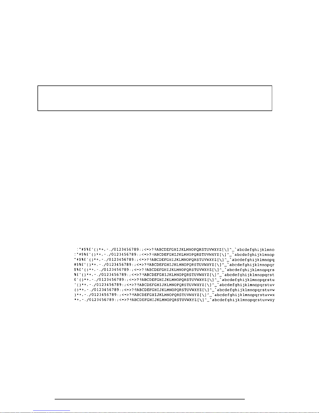
3-22
3.9 Printer Test
To execute the Printer Test, select 6 from the DIAGNOSTIC TEST MENU, press Enter and
follow the directions displayed on the screen. The Printer Test contains three subtests that
test the output of the printer connected to the 400 series. The following messages will appear
after selecting the Printer Test from the DIAGNOSTIC TEST MENU. Answer each of the
following questions with an appropriate response to execute the test.
NOTE: An IBM compatible printer must be connected to the system to execute this
test.
The following message will appear when the printer test is selected:
channel#1 = XXXXh
channel#2 = XXXXh
channel#3 = XXXXh
Select the channel number (1-3) ?
The printer I/O port address is specified by the XXXXh number. The 400 series supports
three printer channels. Select the printer channel number, and press Enter to execute the
selected subtest.
Subtest 01 Ripple Pattern
This subtest prints characters for codes 20h through 7Eh line-by-line while
shifting one character to the left at the beginning of each new line.
400 Series
Page 72
3-23
Subtest 02 Function
This subtest is for IBM compatible printers, and tests the following functions:
Normal print
Double width print
Compressed print
Emphasized print
Double strike print
All characters print
This subtest prints the various print types shown below:
PRINTER TEST
1. THIS LINE SHOWS NORMAL PRINT.
2. THIS LINE SHOWS DOUBLE-WIDTH PRINT.
3. THIS LINE SHOWS COMPRESSED PRINT.
4. THIS LINE SHOWS EMPHASIZED PRINT.
5. THIS LINE SHOWS DOUBLE-STRIKE PRINT.
6. ALL CHARACTERS PRINT
!"#$%&'()*+,./0123456789:;<=>?@ABCDEFGHIJKLMNOPQRSTUVWXYZ[\]^_`abcdefghijklmn
opqrstuvwxyz{|}~
Subtest 03 Wraparound
NOTE: To execute this subtest, a printer wraparound connector must be
connected to the computer’s printer port. The printer wraparound
connector (34M741986G01) wiring diagram is described in Appendix F.
This subtest checks the output and bidirectional modes of the data control and
status lines through the printer wraparound connector.
400 Series
Page 73

3-24
3.10 Async Test
To execute the Async Test, select 7 from the DIAGNOSTIC TEST MENU, press Enter and
follow the directions displayed on the screen. The async test contains eight subtests that test
the 400 series asynchronous communication functions. Move the highlight bar to the subtest
you want to execute and press Enter.
Subtests 01 through 04 require the following data format:
Method: Asynchronous
Speed: 9600BPS (Subtests 01 to 05)
38400BPS (Subtests 06 to 08)
Data: 8 bits and one parity bit (EVEN)
Data pattern: 20h to 7Eh
The following message will appear at the bottom of the screen when subtests 01, 03, 04, and
05 are selected:
Channel#1 = XXXXh
Channel#2 = XXXXh
Channel#3 = XXXXh
Select the Channel number (1/2/3)
The serial I/O port address is specified by the XXXXh number. Select the serial port channel
number, and press Enter to start the subtest.
Subtest 01 Wraparound (board)
NOTE: To execute this subtest an RS-232-C wraparound connector
(34M741621G01) must be connected to the RS-232-C port. The RS-232-C
wraparound connector wiring diagram is described in Appendix F.
This subtest checks the data send/receive function through the wraparound
connector.
Subtest 02 Board (#1) <=> board (#2)
NOTE: To execute this subtest, an RS-232-C cable (9-pin to 9-pin) must
be connected to boards 1 and 2. The RS-232-C direct cable wiring
diagram is described in Appendix F.
This subtest checks the data send/receive function through the RS-232-C
direct cable.
400 Series
Page 74
3-25
Subtest 03 Point to point (Send)
NOTE: To execute this subtest, two machines must be connected with an
RS-232-C direct cable. One machine should be set as “send”(subtest 03)
and the other set as ‘receive’ (subtest 04). The wiring diagram for the
RS-232-C direct cable is described in Appendix F.
This subtest sends 20h through 7Eh data to the receive side, then receives the
sent data and compares it to the original data.
Subtest 04 Point to point (Receive)
This subtest is used with subtest 03 described above. This subtest receives the
data from the send side, then sends the received data.
Subtest 05 Interrupt Test
This subtest checks the Interrupt Request Level of IRQ 4, 3, and 5 from the
send side.
NOTE: Before conducting subtests 06 to 08, you must execute
SIRDRV.COM to enable the infrared communication port.
Subtest 06 Infra_red Wrap_around test
This subtest checks the data send/receive function through the IrDA port.
Subtest 07 Infra_red Transmit mode
This subtest checks the data send function through the IrDA port.
Subtest 08 Infra_red Receive mode
This subtest checks the data receive function through the IrDA port.
400 Series
Page 75

3-26
3.11 Hard Disk Test
To execute the Hard Disk Test, select 8 from the DIAGNOSTIC TEST MENU. Press Enter
and follow the directions displayed on the screen. The hard disk test contains 10 subtests that
test the 400 series hard disk drive functions. The following messages will appear after selecting the hard disk test from the DIAGNOSTIC TEST MENU. Answer each of the following
questions with an appropriate response to execute the test:
NOTE: The contents of the hard disk will be erased when subtest 02, 03, 04, 05, 06,
08, 09, or 10 is executed. Before running the test, transfer the contents of the hard
disk to a floppy disk(s). This should be done with the BACKUP command in the
Toshiba Companion Utility. Do not use the MS-DOS BACKUP command.
After the hard disk test is completed, execute the Toshiba MS-DOS FDISK command,
which will set the partition. Next, execute the Toshiba MS-DOS FORMAT command.
Refer to the Toshiba MS-DOS manual for details.
1. When you select the hard disk test from the DIAGNOSTIC TEST MENU, the
following message will appear:
Test drive number select (1:HDD#1,2:HDD#2,0:HDD1&2) ?
2. Select the hard disk drive number to be tested and press Enter. The following
message will appear:
HDC F/W error retry (1:yes,2:no) ?
3. This message is used to select the retry operation when the hard disk controller
detects an error. Select 1 or 2 and press Enter. The following message will
appear:
Data compare error dump (1:no,2:yes) ?
4. This message is used to select the error dump operation when a data compare
error is detected. Select 1 or 2 and press Enter. The following message will
appear:
Detail status display (1:no,2:yes) ?
5. This message is used to select whether or not the HDD status is displayed on the
screen. The HDD status is described in section 3.16. Select 1 or 2 and press
Enter.
400 Series
Page 76

3-27
6. The Hard Disk Test message will appear after you respond to the Detail Status
prompt. Select the number of the subtest you want to execute and press Enter.
The following message will appear during each subtest.
HARD DISK TEST XXXXXXX
SUB-TEST : XX
PASS COUNT: XXXXX ERROR COUNT: XXXXX
WRITE DATA: XX READ DATA : XX
ADDRESS : XXXXXX STATUS : XXX
The first three digits of the ADDRESS indicate which cylinder is being tested, the
fourth digit indicates the head and the last two digits indicate the sector.
The first digit of the STATUS number indicates the drive being tested and the last
two digits indicate the error status code as explained in table 3-3.
Subtest 01 Sequential Read
This subtest is a sequential reading of all the tracks on the HDD starting at
track 0. When all the tracks on the HDD have been read, the test starts at the
maximum track and reads the tracks on the HDD sequentially back to track 0.
Subtest 02 Address Uniqueness
This subtest writes unique address data to each sector of the HDD track-bytrack. The data written to each sector is then read and compared with the
original data. There are three ways the HDD can be read:
• Forward sequential
• Reverse sequential
• Random
Subtest 03 Random Address/Data
This subtest writes random data to random addresses on the HDD cylinder,
head, and sector. This data is then read and compared to the original data.
400 Series
Page 77
3-28
Subtest 04 Cross Talk & Peak Shift
This subtest writes eight types of worst pattern data (shown below) to a
cylinder, then reads the data while moving from cylinder to cylinder.
Worst pattern data Cylinder
‘B5ADAD’ 0 cylinder
‘4A5252’ 1 cylinder
‘EB6DB6’ 2 cylinder
‘149249’ 3 cylinder
’63B63B’ 4 cylinder
‘9C49C4’ 5 cylinder
‘2DB6DB’ 6 cylinder
‘D24924’ 7 cylinder
Subtest 05 Write/read/compare (CE)
This subtest writes B5ADADh worst pattern data to the CE cylinder on the
HDD, then reads the data from the CE cylinder and compares it with the
original data.
Subtest 06 Write specified address
This subtest writes specified data to a specified cylinder and head on the HDD.
Subtest 07 Read specified address
This subtest reads data which has been written to a specified cylinder and head
on the HDD.
Subtest 08 ECC circuit
This subtest checks the Error Check and Correction (ECC) circuit functions of
the specified cylinder and head on the HDD.
Subtest 09 Sequential write
This subtest writes specified 2-byte data to all of the cylinders on the HDD.
Subtest 10 W-R-C specified address
This subtest writes data to a specified cylinder and head on the HDD, then
reads the data and compares it to the original data.
400 Series
Page 78

3-29
3.12 Real Timer Test
To execute the Real Timer Test, select 9 from the DIAGNOSTIC TEST MENU, press Enter
and follow the directions on the screen. The real timer test contains three subtests that test
the 400 series real timer functions. Move the highlight bar to the subtest you want to execute
and press Enter.
Subtest 01 Real Time
A new date and time can be input during this subtest. To execute the real time
subtest follow these steps:
1. Select subtest 01 and the following message will appear:
Current date : XX-XX-XXXX
Current time : XX:XX:XX
Enter new date:
PRESS [ENTER] KEY TO EXIT TEST
2. If the current date is not correct, input the correct date at the “Enter
new date” prompt and press Enter. The following prompt will appear:
3. If the current time is not correct, input the correct time in 24-hour
format.
Pressing Enter toggles between the time and the date. To exit, press Ctrl +
Break.
Subtest 02 Backup Memory
This subtest performs the following backup memory check:
Writes 1-bit of “on” data to address 01h through 80h
Writes 1-bit of “off” data to address 0Eh through 80h
Writes the data pattern AAh through 55h to the RTC 114-byte memory
(address 0Eh to 7Fh)
The subtest reads and compares this data with the original data.
To exit, press Ctrl + Break.
Enter new time :
400 Series
Page 79

3-30
Subtest 03 Real Time Carry
CAUTION: When this subtest is executed, the current date and time are
erased.
This subtest checks the real time clock increments, making sure the date and
time are displayed in the following format:
Current date : 12-31-1994
Current time : 23:59:58
Pressing Enter displays the following:
Current date : 01-01-1995
Current time : 00:00:00
PRESS [Enter] KEY TO EXIT TEST
Press Ctrl + Break to exit.
400 Series
Page 80

3-31
3.13 NDP Test
To execute the NDP test, select 10 from the DIAGNOSTICS TEST MENU, press Enter and
follow the directions on the screen. The NDP test contains one subtest that tests the 400
series NDP functions.
Subtest 01 NDP
This test checks the following functions of NDP:
❑ Control word
❑ Status word
❑ Bus
❑ Addition
❑ Multiplication
Press Ctrl + Break to exit.
400 Series
Page 81
3-32
3.14 Expansion Test
NOTE: To execute this subtest, the PCMCIA wraparound connector is required.
Subtest 01 PCMCIA wraparound (Internal)
This test checks the following signal line of the PCMCIA slot:
❑ Address line
❑ REG#, CE#1, CE#2 line
❑ Data line
❑ Speaker line
❑ Wait line
❑ BSY#, BVD1 line
This subtest is executed in the following order:
Sub# Address Good Bad Contents
01 00001 nn xx Address line
00001 nn xx REG#, CE#1, CE#2
02 00002 ww rr Data line
03 00003 –– –– Speaker line
04 00004 40, 80 xx Wait line (40<xx<80)
05 00005 nn xx Other lines (BSY#, BVD1)
Subtest 02 PCMCIA wraparound (External)
This test checks the signal lines of the enhanced port replicator’s PCMCIA
slots.
Procedures for conducting this test are the same as for subtest 01 PCMCIA
wraparound (Internal) described above.
nn=A0, 90, 80, 00
ww=write data, rr=read data
nn=21, 00
400 Series
Page 82

3-33
3.15 Sound Test
To execute the Sound test, select 12 from the DIAGNOSTICS TEST MENU, press Enter
and follow the directions on the screen. The Sound test contains six subtests that test the 400
series Sound functions.
Subtest 01 CODEC (REC/PLAY)
NOTE: To execute this subtest, the internal microphone and internal
headphone (or internal speaker) are required.
Test the functions of the Codec (ES688) A/D, D/A converter. At the same
time, test the microphone and headphone terminals. When you execute this
subtest the following message is displayed:
[Quick REC & PLAY for ES488/688]
Press any key to *** REC ***
Press any key, start recording, and immediately play the sound. (It takes three
seconds.)
Subtest 02 FM Synthesizer
Test the OPL# (YMF262) functions. Connect the headphone, and check the
scale of right and left side. Also check the sound adjustment volume.
Subtest 03 SINE wave playback
This subtest expands the sine wave data table to 64KB and creates sine wave
data. The play data is transferred between DMA and CODEC, and plays the
sound. (It is a long beep.) Also, using the oscilloscope, observe the sine
waveform.
Subtest 04 Joystick
To execute this subtest, a port replicator and joystick are required. For minimum sampling data, turn the stick to the upper left, and press the A or B
button. For maximum sampling data, turn the stick to lower right and press
the A or B button (it must be a different button than the one used for minimum
sampling data). If two sampling data are the same, an error occurs.
Subtest 05 MIDI/Joystick port
Conduct a wraparound test on the MIDI/Joystick port.
400 Series
Page 83
3-34
Subtest 06 Codec line in/out (record sound/replay)
Load the file ESS688L.COM. Connect a sound source such as a CD player or
stereo to the line-in port. Next, connect an output device such as an amplifier
for the internal speaker or a radio/cassette player to the line-out port.
After making the connections, a dialogue box will be displayed. Press Enter
to play a recorded sound. About three seconds after the recorded sound is
played, the dialogue box will be displayed again.
NOTE: An enhanced port replicator must be connected to conduct the
line-out test.
400 Series
Page 84

3-35
3.16 CD-ROM Test
First make sure the CD-ROM driver (CDROMDRV.COM) is installed and insert the test
media CD (Toshiba-EMI Test Disk TDY-03). To execute the CD-ROM test, select 13 from
the DIAGNOSTICS TEST MENU, press Enter and follow the directions on the screen. The
CD-ROM test contains four subtests that test the 400 series CD-ROM functions.
Subtest 01 Sequential Read
This subtest is a sequential reading of one block unit (512 bytes) of all logical
addresses.
Subtest 02 Random Address/Data
This subtest reads one-block data and multi-block data from a random address
200 times.
Subtest 03 Read Specified Address
This subtest reads one-block data from a specified address.
Subtest 04 Playback Music
This subtest reads track data from a specified track and plays the sound.
400 Series
Page 85
3-36
3.17 Error Code and Error Status Names
Table 3-2 lists the error codes and error status names for the Diagnostic Test.
Table 3-2 Error codes and error status names (1/3)
Device name Error code Error status name
(COMMON) FF Data Compare Error
SYSTEM 01 ROM Checksum Error
Memory 01 Parity Error
02 Protected Mode Not Changed
14 Memory Read/Write Error
DD Cache Memory Error
Keyboard 01 Mouse Interface Error
02 IPS Interface Error
03 Interface Error
04 Retransmit Error
05 Mouse Handler Not Supported
06 PS/2 Mouse & IPS Not
FDD 01 Bad Command
02 Address Mark Not Found
03 Write Protected
04 Record Not Found
06 Media Removed
08 DMA Overrun Error
09 DMA Boundary Error
10 CRC Error
20 FDC Error
40 Seek Error
60 FDD Not Drive Error
80 Time Out Error
EE Write Buffer Error
Printer 01 Time Out
08 Fault
10 Select Line
20 Out Of Paper
40 Power Off
80 Busy Line
ASYNC 01 DSR On Time Out
02 CTS On Time Out
04 RX-READY Time Out
08 TX-BUFFER Full Time Out
10 Parity Error
400 Series
Page 86
3-37
Table 3-2 Error codes and error status names (2/3)
Device name Error code Error status name
ASYNC (cont.) 20 Framing Error
40 Overrun Error
80 Line Status Error
88 Modem Status Error
HDD 01 Bad Command Error
02 Address Mark Not Found
04 Record Not Found
05 HDC Not Reset Error
07 Drive Not Initialized
08 HDC Overrun (DRQ)
09 DMA Boundary Error
0A Bad Sector
0B Bad Track Error
10 ECC Error
11 ECC Recover Enabled
20 HDC Error
40 Seek Error
80 Time Out Error
AA Drive Not Ready
BB Undefined Error
CC Write Fault
E0 Status Error
EE Access Time Out Error
400 Series
NDP 01 No Co-Processor
02 Control Word Error
03 Status Word Error
04 Bus Error
05 Addition Error
06 Multiply Error
PCMCIA C1 Address Line Error
C2 REG# Line Error
C3 CE#1 Line Error
C4 CE#2 Line Error
C5 DATA Line Error
C6 WAIT Line Error
C7 BSY# Line Error
C8 BVD1 Line Error
CD No PCMCIA
Page 87
3-38
Table 3-2 Error codes and error status names (3/3)
Device name Error code Error status name
CD-ROM 01 BAD COMMAND
02 ILLEGAL LENGTH
03 UNIT ATTENTION
04 MEDIA CHANGE REQUEST
05 MEDIA DETECTED
06 ADDITIONAL SENSE
09 BOUNDARY ERROR
11 CORRECTED DATA ERROR
20 DRIVE NOT READY
40 SEEK ERROR
80 TIME OUT
90 RESET ERROR
B0 ADDRESS ERROR
400 Series
Page 88
3-39
3.18 Hard Disk Test Detail Status
When an error occurs in the hard disk test, the following message is displayed:
HDC status = XXXXXXXX
Detailed information about the hard disk test error is displayed on the screen by an eight-digit
number. The first four digits represent the hard disk controller (HDC) error status number
and the last four digits are not used.
The hard disk controller error status is composed of 2 bytes; the first byte displays the contents of the HDC status register in hexadecimal form and the second byte displays the HDC
error register.
The contents of the HDC status register and error register are listed in tables 3-3 and 3-4.
Table 3-3 Hard disk controller status register contents
Bit Name Description
7 BSY “0” --- HDC is busy.
(Busy) “1” --- HDC is ready.
6 DRDY “0” --- Hard disk drive is not ready to accept any command.
(Drive ready) “1” --- Hard disk drive is ready.
5 DWF “0” --- DWF error is not detected.
(Drive write fault) “1” --- Write fault condition occurred.
4 DSC “0” --- The hard disk drive heads are not settled over a track.
(Drive seek “1” --- The hard disk drive heads are settled over a track.
complete)
3 DRQ “0” --- Drive is not ready for data transfer.
(Data request) “1” --- Drive is ready for data transfer.
2 CORR “0” --- Other
(Corrected data) “1” --- Correctable data error is corrected.
1 IDX “0” --- Other
(Index) “1” --- Index is sensed.
0 ERR “0” --- Other
(Error) “1” --- The previous command was terminated with some error.
400 Series
Page 89
3-40
Table 3-4 Error register contents
Bit Name Description
7 BBK1 “0” Other
(Bad block “1” A bad block mark is detected.
mark)
6 UNC “0”There is no uncorrectable data error.
(Uncorrectable) “1”Uncorrectable data error has been detected.
5 —— Not used
4 IDNF “0” Other
(Identification) “1”There was no ID field in the requested sector.
3 —— Not used
2 ABRT “0” Other
(Abort) “1” Illegal command error or a drive status error occurs.
1 TK00 “0” The hard disk has found track 0 during a recalibrate command.
(Track 0) “1” The hard disk could not find track 0 during a recalibrate command.
0 —— Not used.
400 Series
Page 90
3-41
3.19 Hard Disk Format
This command executes hard disk formatting. There are two types of hard-disk formatting:
❑ Low-level (physical) formatting
❑ MS-DOS (logical) formatting
This hard disk format function performs a low-level format of the hard disk and executes the
following hard disk formats and check:
1. All track FORMAT
2. Good track FORMAT
3. Bad track FORMAT
4. Bad track CHECK
NOTE: The contents of the hard disk will be erased when this program is
executed. Before executing the function, transfer the contents of the hard
disk onto a floppy disk(s). This can be done with the BACKUP in the Toshiba
Companion Utility. See the Toshiba MS-DOS manual for details.
3.19.1 Function Description
1. All track FORMAT
This option performs a low-level format of all the tracks on the hard disk as shown
in Table 3-5 below:
NOTE: Before executing the all track format option, check for bad tracks
using the Bad Track CHECK option or display a list of bad tracks on the
HDD.
Table 3-5 Hard disk formatting sequence
Items (MK1926FCV)
Storage capacity (MB)
Formatted 815
Number of disks 3
Data heads 6
Rotation speed (rpm) 4200
Recording method 8-9 RLL
400 Series
Data surfaces 6
Bytes per sector 512
Page 91
3-42
2. Good track FORMAT
This option formats a specified cylinder and track as a good track. If a good track
is formatted as a bad track, use this option to change the track to a good track.
3. Bad track FORMAT
This option formats a specified cylinder and track as a bad track. If a bad track is
detected, use this option to label it as a bad track.
4. Bad track CHECK
This option searches the hard disk for bad tracks by reading data to all the tracks
on the hard disk. A list of bad tracks is displayed when the program is complete.
If an error other than a bad track is detected, the program is automatically terminated.
3.19.2 Operations
NOTE: After the HDD has been formatted, execute the Toshiba MS-DOS FDISK
command, to partition the HDD. Next, execute the Toshiba MS-DOS FORMAT command. Refer to the Toshiba MS-DOS manual for more information about using these
commands.
Selecting TEST 2 and pressing Enter in the DIAGNOSTIC MENU displays the following
messages:
DIAGNOSTICS - HARD DISK FORMAT : VX.XX
1 - All track FORMAT
2 - Good track FORMAT
3 - Bad track FORMAT
4 - Bad track CHECK
9 - Go to TEST MENU
↑↓→← : Select items, Enter: Finish, Esc: Exit
1. All track FORMAT
Pressing 1 selects All track FORMAT which lets you format the entire disk.
[All track FORMAT]
Drive : #1 = HDD #2 = Non
Cylinder : XXXX
Head : XX
Sector : XX
<<< Model name = >>>
400 Series
Page 92

3-43
The following selections also appear at the bottom of the screen in succession:
Drive number select (1:#1,2:#2) ?
(a) Select a drive number and press Enter. The following message will appear:
Interleave number (1/1 ~ 8) ?
(b) Select an interleave number, 1 ~ 8 and press Enter. Pressing only Enter
selects 1.
Unlock format select (1:no/2:yes)
(c) Select whether the disk has an unlock format.
NOTE: This option appears only when an HDD manufactured by JVC
is installed. For JVC HDDs, which are the only disks with unlock
formats, you must select 2 (yes). If 1 is selected with a JVC disk, an
error will be generated. The system defaults to 1 and this message does
not appear when other disks are installed.
(d) Bad track register
Next, the Bad Track register prompt will appear as shown below. Enter the
cylinder and head numbers of bad tracks and press Enter. Note that if there
are no bad tracks, pressing Enter alone is the same as executing All Track
Format described in item (e) below.
[ WARNING : Current DISK data will be
completely destroyed ]
Press Bad cylinder number (dddd)] key ?
Press Bad head number (dd)] key ?
Enter the cylinder and head number in the format above in decimal notation.
Repeat for each bad track you want to format.
After entering the bad tracks, press Enter to execute the format.
(e) All track format
All tracks are formatted as good tracks except those registered as bad tracks
in item (d) above or those identified as bad tracks in track verification described in item (f) below.
400 Series
Page 93

3-44
(f) Track verification
A check is made of all tracks and if an ECC error, ECC-correctable-data
error, or record-not-found error is detected at a track, that track is automatically formatted as a bad track.
2. Good track FORMAT
If a good track has been erroneously formatted as a bad track, you can use this sub
test to reformat the track as a good track. To format a track as a good track, enter
the number for drive, interleave, cylinder, and head as indicated in the screen
prompt shown below.
Drive number select (1:#1, 2:#2) ?
Interleave number (1 / 1 - 8) ?
Press [Cylinder number (dddd)] ?
Press [Head number (dd)] ?
Press Enter to return to the Hard Disk Format menu.
3. Bad track FORMAT
To format a track as a bad track, enter the number for drive, interleave, cylinder,
and head as indicated in the screen prompt shown below.
Drive number select (1:#1, 2:#2) ?
Interleave number (1 / 1 - 8) ?
Press [Cylinder number (dddd)] ?
Press [Head number (dd)] ?
Press Enter to return to the Hard Disk Format menu.
4. Bad track CHECK
This subtest reads the entire disk and displays a list of bad tracks. The test is
terminated in case of a bad track check error. To initiate the subtest enter the
drive number at the prompt shown below.
Drive number select (1:#1, 2:#2) ?
Bad tracks will be displayed in the format shown below.
[[cylinder, head = 0123 03]]
Press Enter to return to the Hard Disk Format menu.
400 Series
Page 94

3-45
3.20 Head Cleaning
3.20.1 Function Description
This function cleans the heads in the FDD by executing a series of head load/seek and read
operations. A cleaning kit is necessary to perform this program.
3.20.2 Operations
1. Selecting test 4 from the DIAGNOSTIC MENU and pressing Enter displays the
following messages:
DIAGNOSTICS - FLOPPY DISK HEAD CLEANING : VX.XX
Mount cleaning disk(s) on drive(s).
Press any key when ready.
2. Remove the Diagnostics Disk from the FDD. Then insert the cleaning disk and
press Enter.
3. When the cleaning start message appears, the FDD head cleaning has begun.
4. The display automatically returns to the DIAGNOSTIC MENU when the program
is completed.
400 Series
Page 95

3-46
3.21 Log Utilities
3.21.1 Function Description
This function logs error information generated while a test is in progress and stores the results
in RAM. This function can store data on a floppy disk or output the data to a printer. If the
power switch is turned off, the error information will be lost. The error information is displayed in the following order:
1. Error count (CNT)
2. Test name (TS-NAME)
3. Subtest number (TS-NAME)
4. Pass count (PASS)
5. Error status (STS)
6. FDD/HDD or memory address (ADDR)
7. Write data (WD)
8. Read data (RD)
9. HDC status (HSTS)
10. Error status name ( ERROR STATUS NAME)
3.21.2 Operations
1. Selecting 5 and pressing Enter in the DIAGNOSTIC MENU logs error informa-
tion into RAM or onto a floppy disk. The error information is displayed in the
following format:
XXXXX ERRORS
CNT TS-NAME PASS STS ADDR WD RD HSTS [STATUS NAME]
001 FDD 02 0000 103 00001 00 00 FDD - WRITE PROTECTED
001 FDD 01 0000 180 00001 00 00 FDD - TIME OUT ERROR
Address
Error status
Pass count HDC status
Subtest number Read data
Test name Write data
Error count Error status name
[[1:Next,2:Prev,3:Exit,4:Clear,5:Print,6:FD Log Read,7:FD Log Write]]
400 Series
Page 96

3-47
2. The error information displayed on the screen can be manipulated by the following
number keys:
The 1 key scrolls the display to the next page.
The 2 key scrolls the display to the previous page.
The 3 key returns to the Diagnostic Menu.
The 4 key erases all error log information in RAM.
The 5 key outputs the error log information to a printer.
The 6 key reads the log information from a floppy disk.
The 7 key writes the log information to a floppy disk.
3. In the case of “error retry OK,” a capital “R” will be placed at the beginning of the
error status. However, it is not added to the error count.
400 Series
Page 97

3-48
3.22 Running Test
3.22.1 Function Description
This function automatically executes the following tests in sequence:
1. System test (subtest number 01)
2. Memory test (subtest number 01, 02, 04, 06)
3. Display test (subtest number 01 to 08)
4. FDD test (subtest number 02)
5. HDD test (subtest number 01, 05)
6. Real timer test (subtest number 02)
7. Printer test (subtest number 03)
8. Async test (subtest number 01)
The system automatically detects the number of floppy disk drives connected to the 400 series
for the FDD test.
3.22.2 Operations
NOTE: Do not forget to load a work disk in the FDD. If a work disk is not loaded, an
error will be generated during the FDD testing.
1. Remove the diagnostics disk from the floppy disk drive and insert the work disk.
2. Select 6 from the Diagnostic Menu and press Enter, the following message will be
displayed:
Printer wrap around test (Y/N) ?
Selecting Y (yes) executes the printer wraparound test. A printer wraparound
connector must be connected to the parallel port on the back of the 400 series to
properly execute this test.
3. Select Y or N and press Enter. The following message will appear:
Serial #A wrap around test (Y/N) ?
Selecting Y (yes) executes the ASYNC wraparound test. An RS-232-C wraparound connector must be connected to the serial port on the back of the 400
series to properly execute this test.
400 Series
Page 98

3-49
4. Select Yes or No and press Enter. The following message will appear :
Mount the work disk(s) on the drive(s),
then press [Enter] key.
[Warning : The contents of the disk(s),
will be destroyed.]
5. This program is executed continuously. To terminate the program, press Ctrl +
Break.
400 Series
Page 99
3-50
3.23 Floppy Disk Drive Utilities
3.23.1 Function Description
This function formats the FDD, copies the floppy disk, and displays the dump list for both the
FDD and HDD.
1. FORMAT
NOTE: This program is only for testing a floppy disk drive. The option is
different from the Toshiba MS-DOS FORMAT command.
This program can format a 5.25-inch or 3.5-inch floppy disk in the following
formats:
(a) 2D: Double-sided, double-density, 48/67.5 TPI, MFM mode, 512 bytes, 9
sectors/track.
(b) 2DD: Double-sided, double-density, double-track, 96/135 TPI, MFM mode,
512 bytes, 9 sectors/track.
(c) 2HD: Double-sided, high-density, double-track, 96/135 TPI, MFM mode,
512 bytes, 18 sectors/track.
2. COPY
This program copies data from a source floppy disk to a target floppy disk.
3. DUMP
This program displays the contents of the floppy disk and the designated sectors of
the hard disk on the display.
3.23.2 Operations
1. Selecting 7 from the DIAGNOSTIC MENU and pressing Enter displays the
following message:
[ FDD UTILITIES ]
1 - FORMAT
2 - COPY
3 - DUMP
9 - EXIT TO DIAGNOSTICS MENU
400 Series
Page 100

3-51
2. FORMAT program
(a) Selecting FORMAT displays the following message:
DIAGNOSTICS - FLOPPY DISK FORMAT : VX.XX
Drive number select (1:A, 2:B) ?
(b) Select a drive number to display the following message:
Type select (0:2DD-2DD,1:2D-2D,2:2D-2HD,3:2HD-2HD) ?
(c) Select a media/drive type number and press Enter. A message similar to the
one below will be displayed:
Warning : Disk data will be destroyed.
Insert work disk into drive A:
Press any key when ready.
(d) Remove the Diagnostics Disk from the FDD, insert the work disk, and press
any key.
The following message will be displayed when the FDD format is executed:
[ FDD TYPE ] : TRACK = XXX
[ FDD TYPE ] : HEAD = X
[ FDD TYPE ] : SECTOR = XX
Format start
[[track, head = XXX X]]
After the floppy disk is formatted, the following message will appear:
Format complete
Another format (1:Yes/2:No) ?
(e) Typing 1 displays the message from step (c) above. Typing 2 returns the test
to the DIAGNOSTIC MENU.
3. COPY program
(a) When COPY is selected, the following message appears:
FLOPPY DISK FORMAT & COPY : VX.XX
Type select (0:2DD-2DD,1:2D-2D,2:2D-2HD,3:2HD-2HD) ?
(b) Selecting a media/drive type number will display a message similar to the one
below:
Insert source disk into drive A:
Press any key when ready.
400 Series
 Loading...