

Toshiba 38VH26P Service Manual

FILE NO. 030-200227
SERVICE MANUAL
COLOUR TELEVISION
VH26 Chassis
38VH26P
PUBLISHED IN JAPAN, Dec., 2002 i

CHAPTER 1 GENERAL ADJUSTMENTS
SAFETY INSTRUCTIONS ........................................................................................................................................3
SET-UP ADJUSTMENT ............................................................................................................................................ 4
SERVICE MODE ...................................................................................................................................................... 6
DESIGN MODE ........................................................................................................................................................ 9
ELECTRICAL ADJUSTMENTS .............................................................................................................................. 10
CIRCUIT CHECK .................................................................................................................................................... 17
GENERAL ADJUSTMENTS
CHAPTER 2 SPECIFIC INFORMATIONS
SETTING & ADJUSTING DATA ............................................................................................................................. 18
LOCATION OF CONTROLS ................................................................................................................................... 19
CHASSIS AND CABINET REPLACEMENT PARTS LIST ......................................................................................21
PC BOARDS BOTTOM VIEW................................................................................................................................. 37
TERMINAL VIEW OF TRANSISTORS ................................................................................................................... 48
CIRCUIT BLOCK DIAGRAM .................................................................................................................................. 50
SPECIFICATIONS .............................................................................................................................................. END
TABLE OF CONTENTS
SPECIFIC INFORMATIONS
APPENDIX:
CIRCUIT DIAGRAM
– 2 –

CHAPTER 1 GENERAL ADJUSTMENTS
SAFETY INSTRUCTIONS
WARNING: BEFORE SERVICING THIS CHASSIS, READ THE “X-RAY RADIATION PRECAUTION”, “SAFETY PRECAU-
TION” AND “PRODUCT SAFETY NOTICE” INSTRUCTIONS BELOW.
X-RAY RADIATION PRECAUTION
1. Excessive high voltage can produce potentially hazardous X-RAY RADIATION. To avoid such hazards, the high
voltage must not be above the specified limit. The nominal
value of the high voltage of this receiver is (A) kV at zero
beam current (minimum brightness) under a (C) V AC power
source. The high voltage must not, under any circumstances,
exceed (B) kV.
Refer to table-1 for high voltage (A), (B) & AC voltage (C).
(See SETTING & ADJUSTING DATA on page 18)
Each time a receiver requires servicing, the high voltage
should be checked following the HIGH VOLTAGE CHECK
procedure in this manual. It is recommended that the reading of the high voltage be recorded as a part of the service
record. It is important to use an accurate and reliable high
voltage meter.
2. The only source of X-RAY RADIATION in this TV receiver
is the picture tube. For continued X-RAY RADIATION protection, the replacement tube must be exactly the same
type tube as specified in the parts list.
3. Some part in this receiver have special safety-related characteristics for X-RAY RADIATION protection. For continued safety, parts replacement should be undertaken only
after referring to the PRODUCT SAFETY NOTICE below.
GENERAL ADJUSTMENTS
SAFETY PRECAUTION
WARNING : Service should not be attempted by anyone unfamiliar with the necessary precautions on this receiver. The following
are the necessary precautions to be observed before servicing this chassis.
1. An isolation transformer should be connected in the power line between the receiver and the AC line before any service is
performed on the receiver.
2. Always discharge the picture tube anode to the CRT conductive coating before handling the picture tube. The picture tube
is highly evacuated and if broken, glass fragments will be violently expelled. Use shatter proof goggles and keep picture tube
away from the unprotected body while handling.
3. When replacing a chassis in the cabinet, always be certain that all the protective devices are put back in place, such as; nonmetallic control knobs, insulating covers, shields, isolation resistor-capacitor network etc.
PRODUCT SAFETY NOTICE
SPECIFIC INFORMATIONS
Many electrical and mechanical parts in this chassis have special safety-related characteristics. These characteristics are
often passed unnoticed by a visual inspection and the protection afforded by them cannot necessarily be obtained by using
replacement components rated for higher voltage, wattage, etc. Replacement parts which have these special safety characteristics are identified in this manual and its supplements; electrical components having such features are identified by
the international hazard symbols on the schematic diagram and the parts list.
Before replacing any of these components, read the parts list in this manual carefully. The use of substitute replacement
parts which do not have the same safety characteristics as specified in the parts list may create shock, fire, X-ray
radiation or other hazards.
– 3 –
WARNING: BEFORE SERVICING THIS CHASSIS, READ THE “X-RAY RADIATION PRECAUTION”, “SAFETY PRECAU-
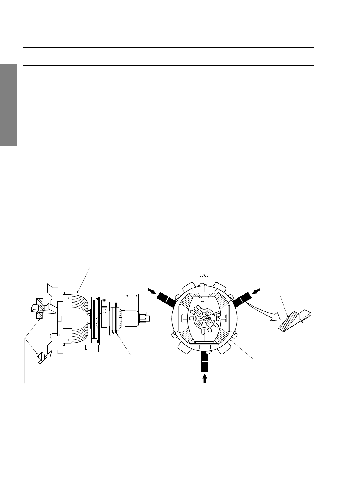
GLASS CLOTH
TAPES
DEFLECTION
YOKE
TEMPORARY
MOUNTING
RUBBER WEDGE
ADHESIVE
DEFLECTION
YOKE
PURITY/
CONVERGENCE
MAGNET ASS'Y
29.1mm(28", 29")
25mm(25")
19mm(19", 20", 21")
14mm(13", 14")
TION” AND “PRODUCT SAFETY NOTICE” ON PAGE 3 OF THIS MANUAL.
SET-UP ADJUSTMENT
■ The following adjustments should be made when a complete realignment is required or a new picture tube is installed.
Perform the adjustments in order as follows :
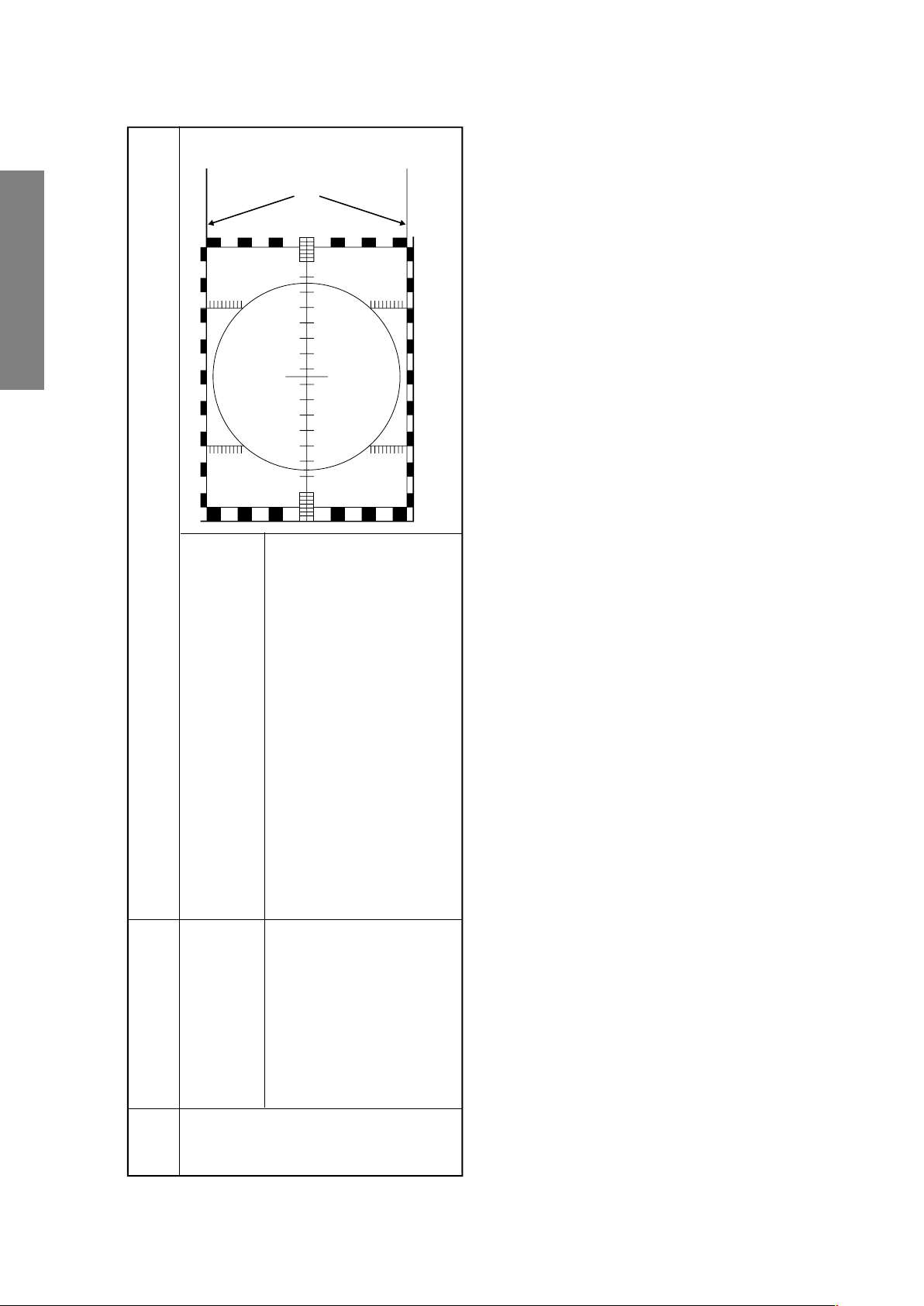
1. Color Purity
2. Convergence
3. White Balance
Note: The PURITY/CONVERGENCE MAGNET assembly and rubber wedges need mechanical positioning.
Refer to figure 1.
GENERAL ADJUSTMENTS
*
COLOR PURITY ADJUSTMENT
NOTE : Before attempting any purity adjustments, the receiver
1. Demagnetize the picture tube and cabinet using a degauss-
2. Set the brightness and contrast to maximum.
3. Use a green raster from among the built-in test signals.
4. Loosen the clamp screw holding the yoke and slide the
SPECIFIC INFORMATIONS
Mounting position of the purity magnet assembly should fit to same position as old one because slightly difference to
the position depend on a kind of tube.
There are no adjustment of purity and convergence in some picture tube (Unified with purity magnet)
5. Remove the Rubber Wedges.
should be operated for at least fifteen minutes.
ing coil.
yoke backward or forward to provide vertical green belt
(zone) in the picture screen.
6. Rotate and spread the tabs of the purity magnet (See figure 2.) around the neck of the picture tube until the green
belt is in the center of the screen. At the same time, enter
the raster vertically.
7. Slowly move the yoke forward or backward until a uniform
green screen is obtained. Tighten the clamp screw of the
yoke temporarily.
8. Check the purity of the red and blue raster.
Figure 1.
– 4 –
CONVERGENCE ADJUSTMENTS
BLU RED
BLU
RED
RED/BLU GRN
RED/BLU
GRN
B
G
R
R
G
B
BGR
RGB
BGR
RGB
R
G
B
B
G
R
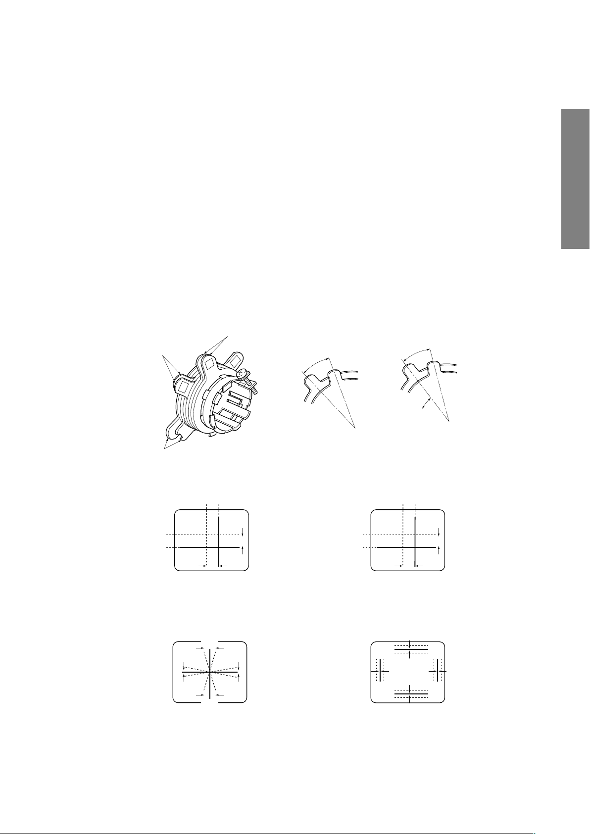
4-POLE MAGNETS MOVEMENT
INCLINE THE YOKE UP (OR DOWN)
6-POLE MAGNETS MOVEMENT
Center Convergence by Convergence Magnets
Circumference Convergence by DEF Yoke
INCLINE THE YOKE RIGHT (OR LEFT)
4-POLE
MAGNETS
PURITY
MAGNETS
6-POLE
MAGNETS
ADJUST THE ANGLE
(VERTICAL LINES)
FIXED
ROTATE TWO TABS
AT THE SAME TIME
(HORIZONTAL LINES)
CONVERGENCE MAGNET ASSEMBLY ADJUSTMENT OF MAGNETS
NOTE: Before attempting any convergence adjustments, the
receiver should be operated for at least fifteen minutes.
■ CENTER CONVERGENCE ADJUSTMENT
1. Use the cross-dot pattern from among the built-in test signals.
2. Set the brightness and contrast for well defined pattern.
3. Adjust two tabs of the 4-Pole Magnets to change the angle between them (See figure 2.) and superimpose red
and blue vertical lines in the center area of the picture
screen.
4. Turn the both tabs at the same time keeping the angle
constant to superimpose red and blue horizontal lines at
the center of the screen.
5. Adjust two tabs of 6-Pole Magnets to superimpose red/
blue line and green one. Adjusting the angle affects the
vertical lines and rotating both magnets affects the horizontal lines.
6. Repeat adjustments 3, 4, 5 keeping in mind red, green
and blue movement, because 4-Pole Magnets and 6-Pole
Magnets have mutual interaction and make dot movement
complex.
■ CIRCUMFERENCE CONVERGENCE ADJUSTMENT
1. Loosen the clamping screw of deflection yoke slightly to
allow the yoke to tilt.
2. Temporarily put a wedge as shown in figure 1. (Do not
remove cover paper on adhesive part of the wedge.)
3. Tilt front of the deflection yoke up or down to obtain better
convergence in circumference. (See figure 3.) Push the
mounted wedge into the space between picture tube and
the yoke to fix the yoke temporarily.
4. Put other wedge into bottom space and remove the cover
paper to stick.
5. Tilt front of the yoke right or left to obtain better convergence in circumference. (See figure 3.)
6. Keep the yoke position and put another wedge in either
upper space. Remove cover paper and stick the wedge
on picture tube to fix the yoke.
7. Detach the temporarily mounted wedge and put it in another upper space. Stick it on picture tube to fix the yoke.
8. After fixing three wedges, recheck overall convergence.
Tighten the screw firmly to fix the yoke and check the yoke
is firm.
9. Stick three adhesive tapes on wedges as shown in figure
1.
GENERAL ADJUSTMENTS
SPECIFIC INFORMATIONS
Figure 2.
Figure 3. Dot Movement Pattern
– 5 –
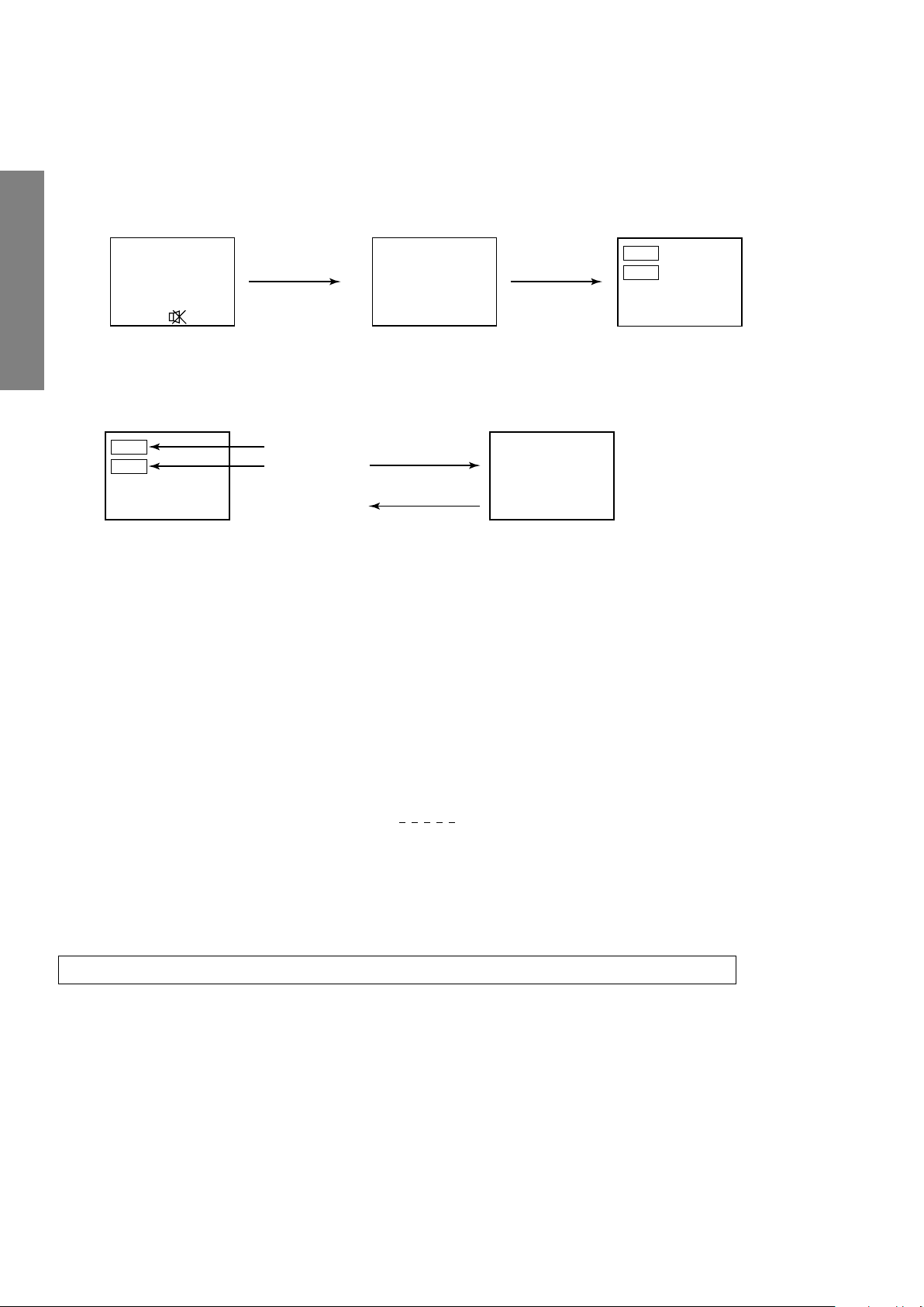
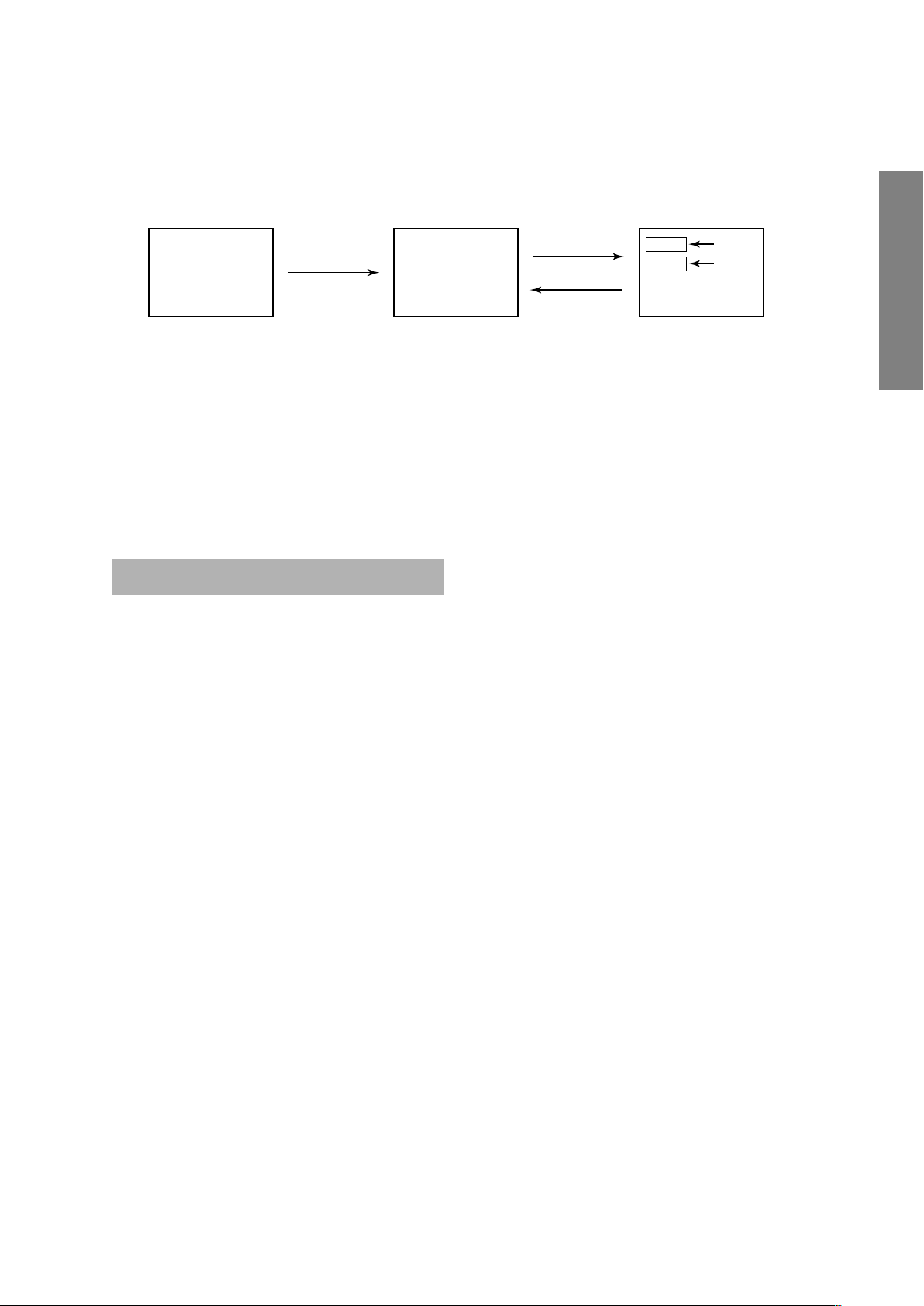
1. ENTERING TO SERVICE MODE
S
(Service mode display)
Item
Data
Mute or
Adjustment mode
Item
Data
Service mode
S
Press
Press
ITEM
DATA
1) Press o button once on
Remote Control.
GENERAL ADJUSTMENTS
2. DISPLAYING THE ADJUSTMENT MENU
1) Press MENU button on TV.
3. KEY FUNCTION IN THE SERVICE MODE
The following key entry during display of adjustment menu provides special functions.
SERVICE MODE
2) Press o button again to
keep pressing.
3) While pressing the o button,
press MENU button on TV set.
SPECIFIC INFORMATIONS
A single horizontal line ON/OFF: INFO button (on Remote) or a button (on TV)
Test signal selection : a button (on Remote)
Selection of the adjustment items : Channel s/t (on TV or Remote)
Change of the data value : Volume ; +/– (on TV or Remote)
Adjustment menu mode ON/OFF : MENU button (on TV)
Initialization of the memory (QA02) : CALL + Channel button on TV (s)
Reset the count of operating protect
circuit to “00”: CALL + Channel button on TV (t)
“RCUT” selection : 1 button
“GCUT” selection : 2 button
“BCUT” selection : 3 button
“CNTX” (or “SCNT”) selection : 4 button
“COLC” selection : 5 button
“TNTC” selection : 6 button
Self diagnostic display ON/OFF : 9 button
Color thickness correction
note: Displayed differently as shown below, de-
pending on the setting of the receiving color
system.
COLP (PAL)
COLC (NTSC)
COLS (SECAM)
CAUTION : Never try to perform initialization unless you have changed the memory IC.
– 6 –
4. SELECTING THE ADJUSTING ITEMS
Signal off
NTSC signals (5 patterns)
PAL signals (5 patterns)
1)Every pressing of CHANNEL s button in the service mode changes the adjustment items in the order of table-2.
(t button for reverse order)
Refer to table-2 for preset data of adjustment mode.
(See SETTING & ADJUSTING DATA on page 18)
5. ADJUSTING THE DATA
1) Pressing of VOLUME ; +/– button will change the value of data in the range from 00H to FFH. The variable range
depends on the adjusting item.
6. EXIT FROM SERVICE MODE
1) Pressing POWER button to turn off the TV once.
■ INITIALIZATION OF MEMORY DATA OF QA02
After replacing QA02, the following initialization is required.
1. Enter the service mode, then select any register item.
2. Press and hold the CALL button on the Remote, then press the CHANNEL s button on the TV. The initialization of QA02 has
been completed.
3. Check the picture carefully. If necessary, adjust any adjustment item above.
Perform “Auto search Memory” on the owner’s manual.
CAUTION: Never attempt to initialize the data unless QA02 has been replaced.
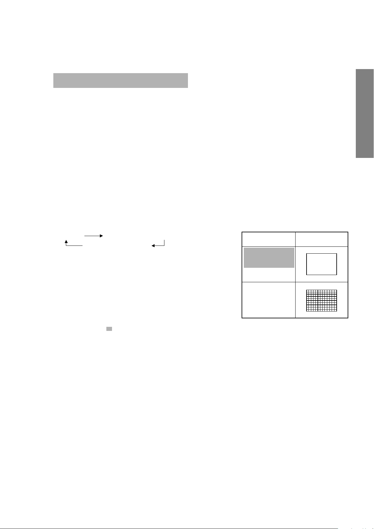
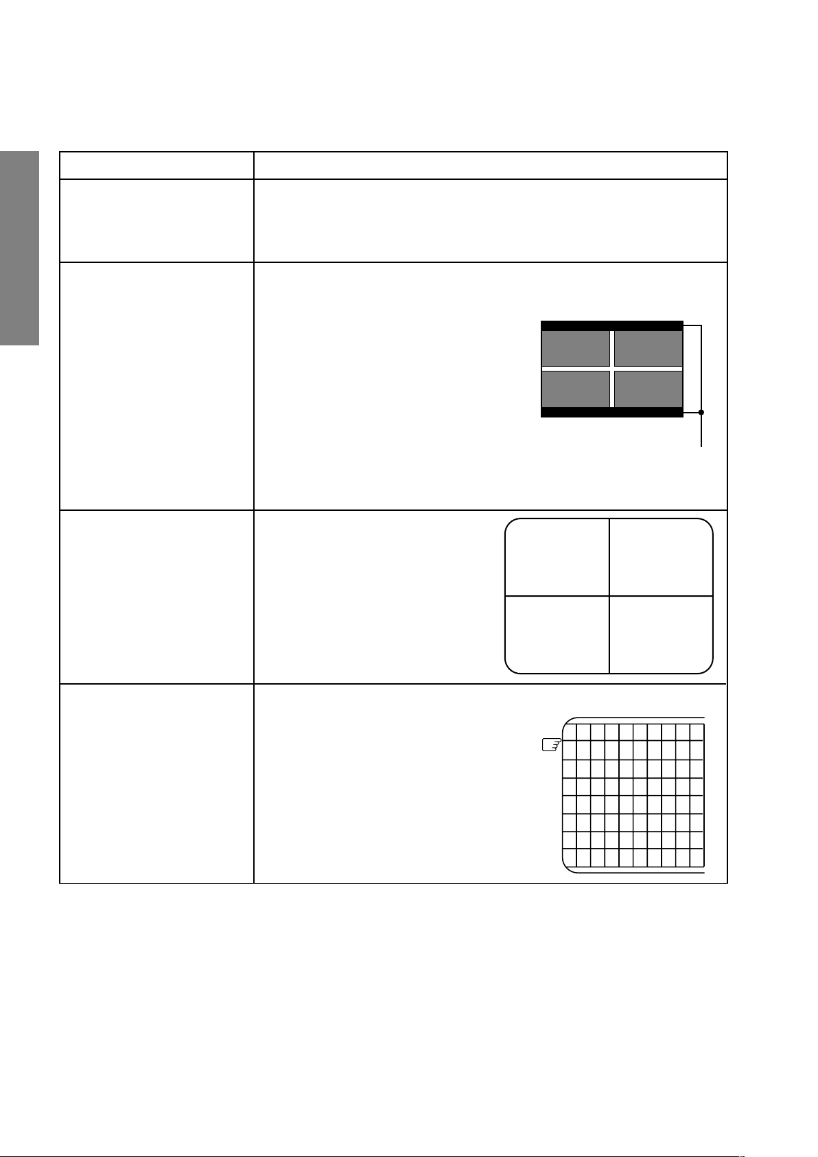
7. TEST SIGNAL SELECTION
1) Every pressing of a button on the Remote Control changes the built-in test patterns on screen as described below
in SERVICE MODE.
GENERAL ADJUSTMENTS
• Red raster
• Green raster
• Blue raster
• All White
• Black cross-hatch
The signals marked with are not usable to display in the Test signal for some model.
*
Signals Picture
SPECIFIC INFORMATIONS
– 7 –

8. SELF DIAGNOSTIC FUNCTION
23******
POWER : 00
BUS LINE : OK
BUS CONT : OK
BLOCK :
UV V1 V2 V3
QV01
<SELF CHECK>
1) Press “9” button on Remote Control during display of adjustment menu in the service mode.
The diagnosis will begin to check if interface among IC’s are executed properly.
2) During diagnosis, the following displays are shown.
Indicated color of mode now selected : Green and Red
Indicated color of other modes : White
GENERAL ADJUSTMENTS
Part number of microcomputer (QA01)
Operation number of protecting circuit ----“00” is nor-
mal.
When indication is other than “00”, over current apts to
flow, and circuit parts may possibly be damaged.
BUS LINE CHECK ----“OK” is normal.
“SDA1-GND” ------------- SDA-GND short circuit.
“SCL1-GND” -------------- SCL-GND short circuit.
“SCL1-SDA1” ------------- SCL-SDA short circuit.
BUS CONT ----“OK” is normal.
When indication shows “Q uuu NG”, the device with
SPECIFIC INFORMATIONS
the number may possibly be damaged.
BLOCK
UV : TV reception mode
V1 : VIDEO 1 input mode (a1)
V2 : VIDEO 2 input mode (a2)
V3 : VIDEO 3 input mode (a3)
Green : Normal
Red : The microcomputer operates to provide judgment
of no video signal. The red color is still indicated
though the signal is input, failure may exist in input
signal line including QV01.
QV01 : In case of indication green ---Normal
In case of indication red with input signal---Failure may exist in output line including QV01.
NOTE: Component which controls character display on
screen is ICF01 (TELETEXT IC.). If this display
function fails to operate due to damage in ICF01,
self diagnosis procedure is as follows.
(1) In case that power indicator is blinking with
interval of 0.5 seconds; it means protecting circuit (Current limiter) is operating, and circuit
components may possibly be damaged. Check
related components.
(2) In case that power indicator is blinking with
interval of 1 second; Protecting circuit does
not operate, but a part of Bus line does not
operate normally. Check Bus line.
The items marked with are not usable to display in the SELF DIAGNOSTIC FUCTION for some model.
*
– 8 –
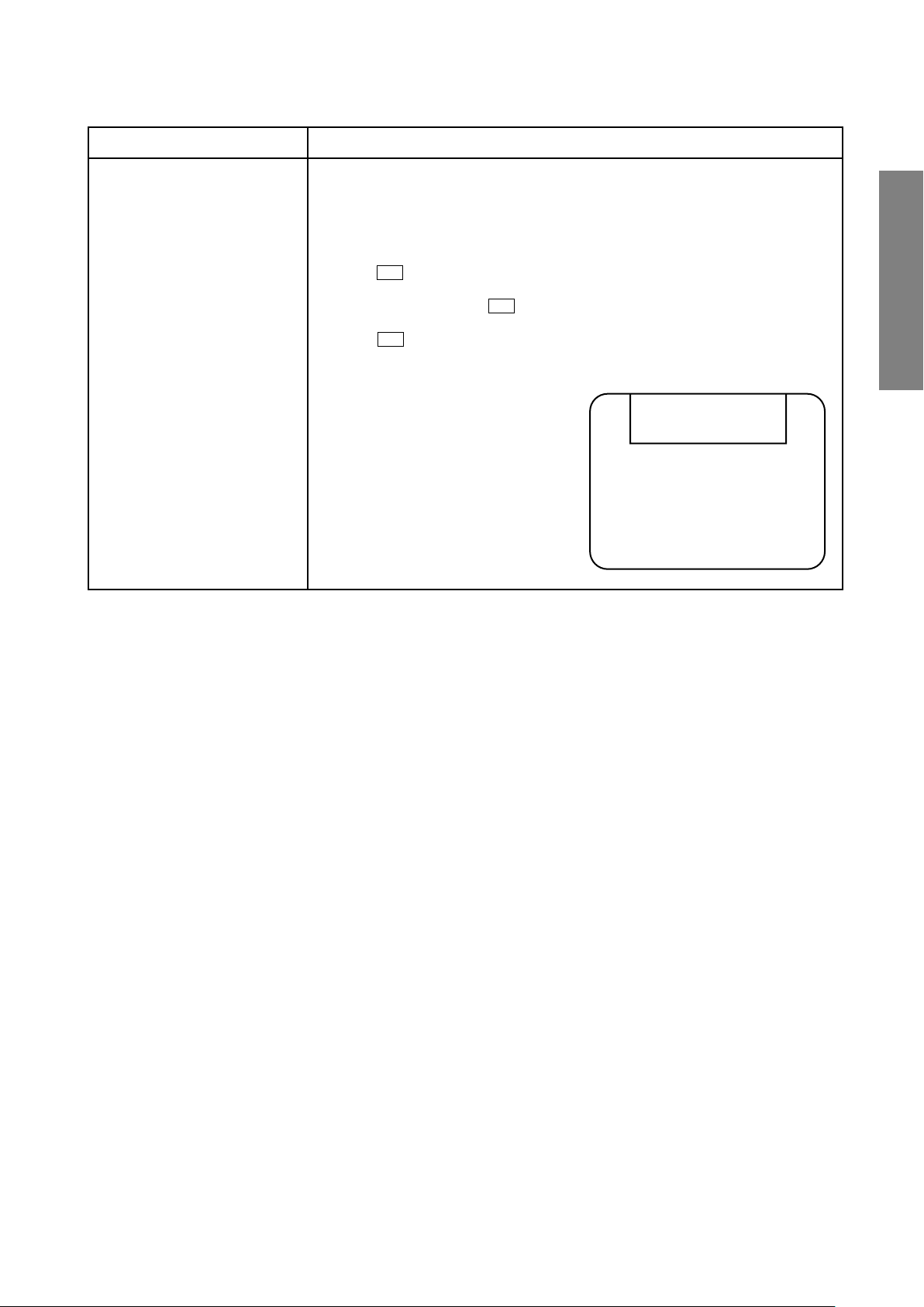
DESIGN MODE
ITEM
DATA
S D
Press
(Design mode) (Adjustment mode)
Press
1. ENTERING TO DESIGN MODE
1) Select the Service mode.
When QA02 is initialized, items “OPT0” and “OPT1” of DESIGN MODE are set to the data of the representative model of this
chassis family.
Therefore, because ON-SCREEN specification remains in the state of the representative of model. This model is required to
reset the data of items “OPT0” and “OPT1”.
2. SELECTING THE ADJUSTING ITEMS
Every pressing of CHANNEL t button in the design mode changes the adjustment items in the order of table-3.
(s button for reverse order)
Refer to table-3 for data of design mode.
(See SETTING & ADJUSTING DATA on page 18)
2) While pressing o or CALL button on
Remote and press MENU button on TV.
3) Press MENU button on TV.
GENERAL ADJUSTMENTS
3. ADJUSTING THE DATA
Pressing of VOLUME s or t button will change the value of data.
SPECIFIC INFORMATIONS
– 9 –
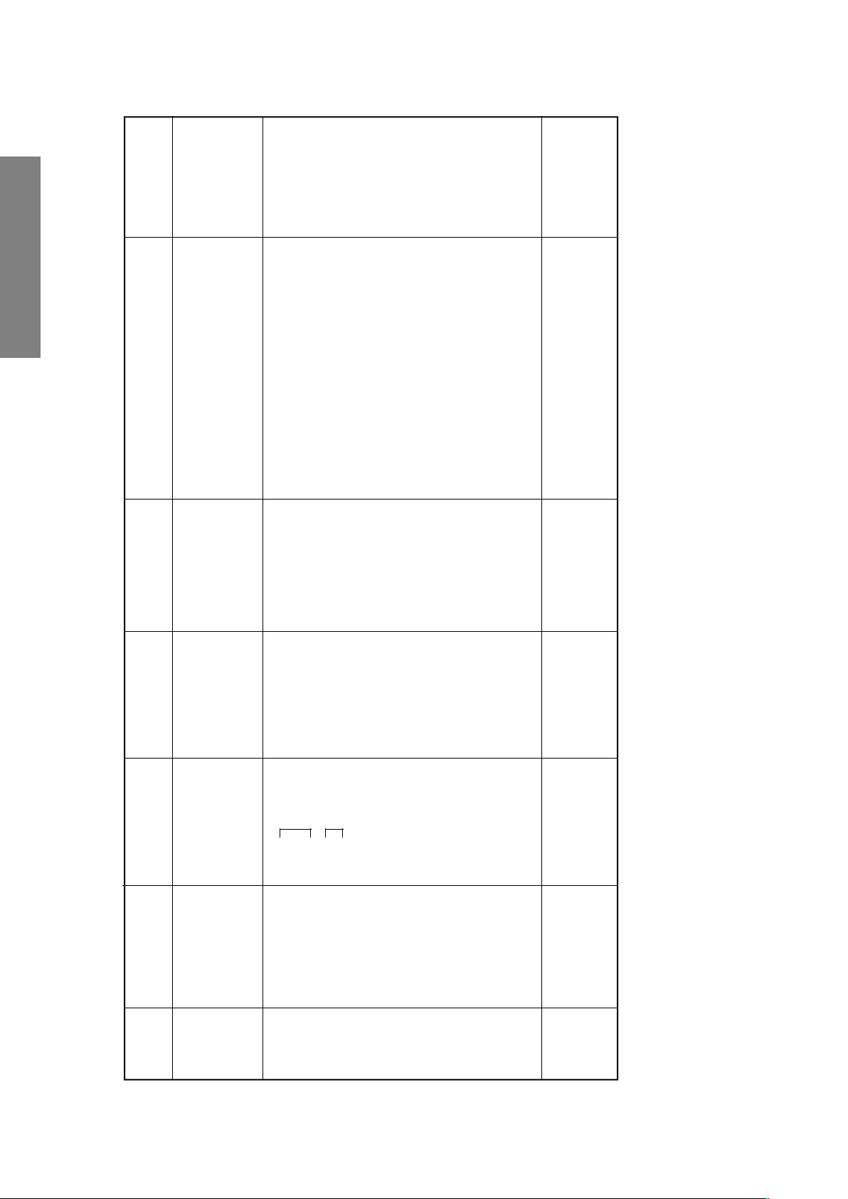
ELECTRICAL ADJUSTMENTS
Belt of vertical retrace
The first
ITEM ADJUSTMENT PROCEDURE
FOCUS VR ADJ
SUB-BRIGHTNESS
(BRTC)
GENERAL ADJUSTMENTS
SPECIFIC INFORMATIONS
Note: Constrict the picture height
until the vertical retrace line
appears adjusting the item
HIT (HEIGHT).
HORIZONTAL POSITION
ADJUSTMENT (HPOS)
VERTICAL POSITION
ADJUSTMENT (VPOS)
1. Enter the service mode, then select any register item.
2. Press the TV/VIDEO button on the Remote until the black cross-bar pattern appears on the screen.
3. Adjust the FOCUS control (on T461) for well defined scanning lines on the picture
screen.
1. Set CONTRAST to minimum, and
BRIGHTNESS to center by adjusting
user controls.
2. Set the TV in service mode to get white
cross-bar of inside pattern.
3. Select BRTC (brightness correction),
and adjust the ; – /+ button to reduce
the value so that white portion of inside
pattern slightly light.
4. Adjust ; – /+ button to increase the
data value of BRTC, and set it just
before the difference between the belt of
vertical retrace and the border of black
portion of inside pattern is visible.
After that, return vertical height and
contrast.
1. Set the TV in service mode, and get
black or white cross-bar signal with
VIDEO button on remote hand unit.
2. Select either HPOS (Horizontal
picture phase) or VPOS (Vertical
picture phase) with CHANNEL s, t
buttons, and adjust horizontal or
vertical picture position in the center
of screen with VOLUME ; – /+
buttons.
VERTICAL AMPLITUDE
ADJUSTMENT (HIT)
1. Set the TV in service mode, and get
black or white cross-hatch signal
with VIDEO button on remote hand
unit.
2. Select HIT (Vertical amplitude) with
CHANNEL s, t buttons, and adjust
vertical amplitude with VOLUME
; – /+ buttons so that vertical amplitude lacks a little.
3. Adjust vertical amplitude with VOLUME ; – /+ buttons so that the first
bar on cross-hatch signal touches
edge of screen.
– 10 –
ITEM ADJUSTMENT PROCEDURE
Light area check
(to show white)
Dark area check
(to show black)
WHITE BALANCE
ADJUSTMENT
CUTOFF ADJUSTMENT
•
(RCUT)
(GCUT)
(BCUT)
DRIVE ADJUSTMENT
•
(GDRV)
(BDRV)
1. Set Contrast to 40, and brightness to +20 by picture control.
2. Set the TV in service mode, and get the inside W/B adjusting signal with VIDEO
button.
3. Select RCUT, GCUT and BCUT with CHANNEL s, t buttons, to set individual
values to Initial reference data, and to set GDRV and BDRV to Initial reference
data with VOLUME ; – /+ buttons (See page 18).
4. Press -/- - button on the remote control and rotate Screen VR to get one slight
horizontal line on screen.
Note: Every pressing of -/- - button provides Horizontal line picture and Normal
picture alternately.
5. Press -/- - button to release horizontal line picture, and select the two other colors
which did not light in the above step with CHANNEL s, t buttons. Then tap VOLUME ; – /+ buttons so that three colors slightly light in the same level.
X To correct white balance in light area,
select GDRV and BDRV with CHANNEL
s, t buttons to adjust.
X To correct white balance in dark area,
perform fine adjustment of RCUT, GCUT
and BCUT.
GENERAL ADJUSTMENTS
SPECIFIC INFORMATIONS
– 11 –
4 ± 1.5 lines
GENERAL ADJUSTMENTS
)
2
HIGH LIGHT
(103cd /m
8750K-0.002uv
)
2
Dark part
(17cd/m
8750K-0.002uv
is the same as
before.
* Adjustment range
0 ± 10 mV
SPECIFIC INFORMATIONS
VR adjustment and white balance
1. This item shall be adjust after the screen
lines of the sub-bright signal.
adjustment.
2. Adjust the number of collapsed black
Screen adjustment
Horizontal line mode.
until either of R, G or B lines starts to
1. Set the conditions as shown left &
2. Gradually raise the screen brightness
Screen adjustment
adjustment position.
gleam slightly.
3. Determine that point as the screen VR
brightness of two lines except the one
4. Using RCUT, GCUT and BCUT, raise the
Sub-bright signal
40H
35H
Picture MODE-1
Screen size: 4:3
RCUT
GCUT
BCUT
GDRV
BDRV
Activated horizontal
straight line mode
that gleamed in step 2 until these lines
start to gleam slightly (ie make the screen
almost white).
(CA100), repeat the adjustment steps
until both bright and dark parts become
correct value.
5. Release the horizontal straight line mode.
6. Using the white balance checker
different signal to the level of H.BLK part.
and SBY data items respectively.
1. Adjust the level of B/W part of the colour
2. Adjust the R-Y axis and B-Y axis by SRY
SRY: TP02
SBY: TP01
SECAM Colour bar
Item Name Setting Input signal Measuring point Adjusting method Adjusting standard
(Reference Factory Adjustments)
Sub-bright centre
adjustment
BRTC
Screen adjustment
and white balance
adjustment
(R cut off)
(G cut off)
(B cut off)
(Screen)
RCUT
GCUT
BCUT
Screen
VR
– 12 –
(G drive)
(B drive)
GDRV
BDRV
Secam Black level
adjustment
SRY
SBY
R-Y axis
B-Y axis

2.4 ± 0.1 Vp-p
Adjust the amplitude from the pedestal level
to the white peak.
1.2 ± 0.1 Vp-p
Adjust the amplitude of B-Y.
1.6 ± 0.1 Vp-p
Peak)
* (Pedestal to
Turn on Y-MUTE when adjusting this item.
Adjust the amplitude of B-Y.
Turn on Y-MUTE when adjusting this item.
GENERAL ADJUSTMENTS
SPECIFIC INFORMATIONS
TP46B
Sub-bright signal
(PAL-I Signal)
Picture Mode 1
Screen size: 4:3
Sub-contrast
TP46B
Sub-bright signal
Audio system: I
Picture Mode 1
Sub-colour centre
TP46B
(PAL)
SECAM Colour bar
Screen size: 4:3
Picture Mode 1
Screen size: 4:3
PA L
Sub-colour centre
SECAM
Item Name Setting Input signal Measuring point Adjusting method Adjusting standard
SCNT
COLP
COLS
– 13 –
GENERAL ADJUSTMENTS
SPECIFIC INFORMATIONS
Contact point
PAL Philips Pattern, User adjustment standard
Vertical amplitude [HIT]
Item Adjusting items Adjusting methods
Data adjustment
Vertical
If this is impossible, offset the difference.
Adjust the vertical amplitude by [HIT] so that both upper and
lower flags will disappear from the screen.
(See the right sketch)
PAL Philips Pattern, User adjustment standard
Adjust the vertical position [VPS1] with Philips Pattern so that
the vertical screen position will come to the centre. (See the
right sketch)
Note: Adjust and orient CPT either toward the south and north.
Vertical position [VPS1]
– 14 –
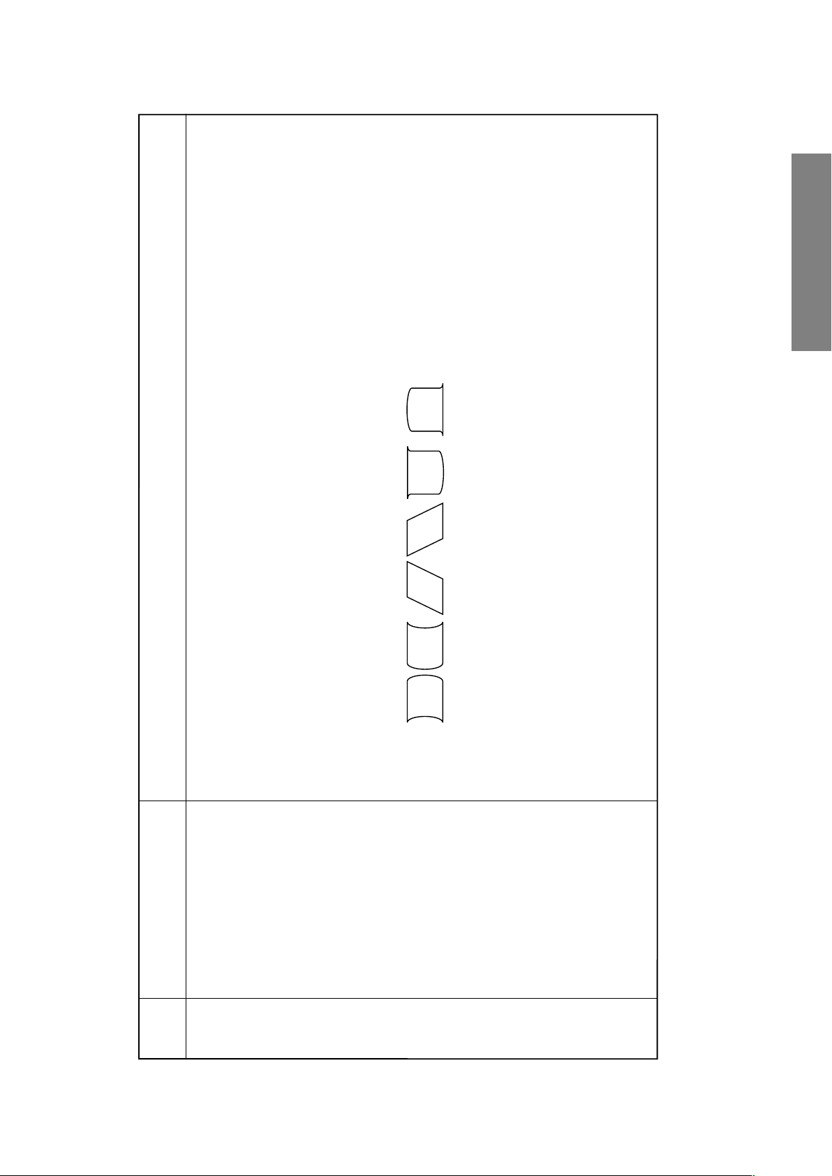
Adjustment methods
(a)
(e)
(b) (c) (d)
(f)
1. Decrease [CPAR] in case of the distortion shown in Fig. (a).
On the contrary, increase [CPAR] in case of the distortion shown in Fig. (b).
2. Decrease [CSAW] in case of the distortion shown in Fig. (c).
On the contrary, increase [CSAW] in case of the distortion shown in Fig. (d).
GENERAL ADJUSTMENTS
SPECIFIC INFORMATIONS
On the contrary, increase [HSC] in case of the distortion shown in Fig. (f).
3. Decrease [HSC] in case of the distortion shown in Fig. (e).
Use PAL Philips Pattern.
Adjusting items
Item
Data adjustment
Horizontal
(1) Use the [HPOS] for the horizontal screen position, and make adjustments so that the position will become a centre.
(2) Use the [WID] to fit the mask to the frames of left and right flags.
(3) Use the [PARA] and [TRAP] become optimum.
Horizontal phase: [HPOS]
Horizontal amplitude: [WID]
DPC correction: [PARA]
[CNR], [CPAR], [HSC] and [CSAW].
(4) In case distortion adjustment is insufficient by the [PARA] [TRAP] adjustments, make adjustments by using the data of
Trapezoidal correction: [TRAP]
DPC corner correction: [CNR]
Centre warp: [CPAR]
DPC S correction: [HSC]
Paralleogram correction: [CSAW]
(5) Re-adjust item (3) if need.
– 15 –
 Loading...