

Toshiba 37XV553D Schematic
(*1), as indicated by the underlined serial number.
©
SERVICE MANUAL
LCD Color Television
37XV553D
This model is classified as a green product
Ver. 2.00
This Service Manual describes replacement parts for the green product. When repairing this
green product, use the part(s) described in this manual and lead-free solder (*2).
For (*1) and (*2), refer to GREEN PRODUCT PROCUREMENT and LEAD-FREE
SOLDER.
TOSHIBA CORPORATION

IMPORTANT NOTICE
WARNING:
You are requested that you shall not modify or alter the information or data
provided herein without prior written consent by Toshiba. Toshiba shall not
be liable to anybody for any damages, losses, expenses or costs, if any,
incurred in connection with or as a result of such modification or alteration.
THE INFORMATION OR DATA HEREIN SHALL BE PROVIDED "AS IS"
WITHOUT ANY WARRANTY OF ANY KIND, EITHER EXPRESS OR IMPLIED
WARRANTY OF MERCHANTABILITY AND FITNESS FOR A PARTICULAR
PURPOSE.
Toshiba shall not be liable for any damages, losses, expenses or costs, if
any, incurred in connection with or as a result of use of any information or
data provided herein.

IMPORTANT NOTICE
is necessary to view drawings and to activate the functions of this system. Please
up windows are limited by
the enhanced security function and this system may not work. In that case, perform the Internet Explorer
User's Guide
Contents:
Install Autodesk DWF Viewer
Internet Explorer Settings
Operating Environment
Functions Provided on Each Drawing Page
Using with Network
Install Autodesk DWF Viewer
Autodesk DWF Viewer
download and install.
Internet Explorer Settings
When Windows XP SP2 or Windows Vista is used, ActiveX control and pop-
setting using the following procedure to restore normal operation.
1. Windows version check
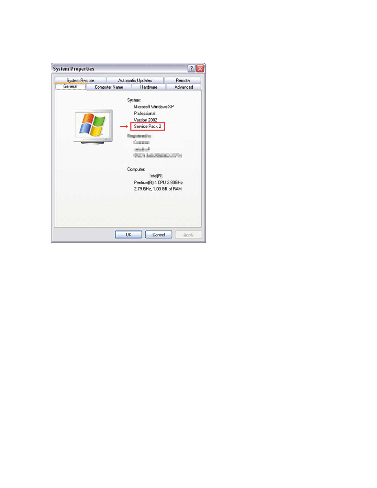
[My Computer (right-click)] - [Properties]
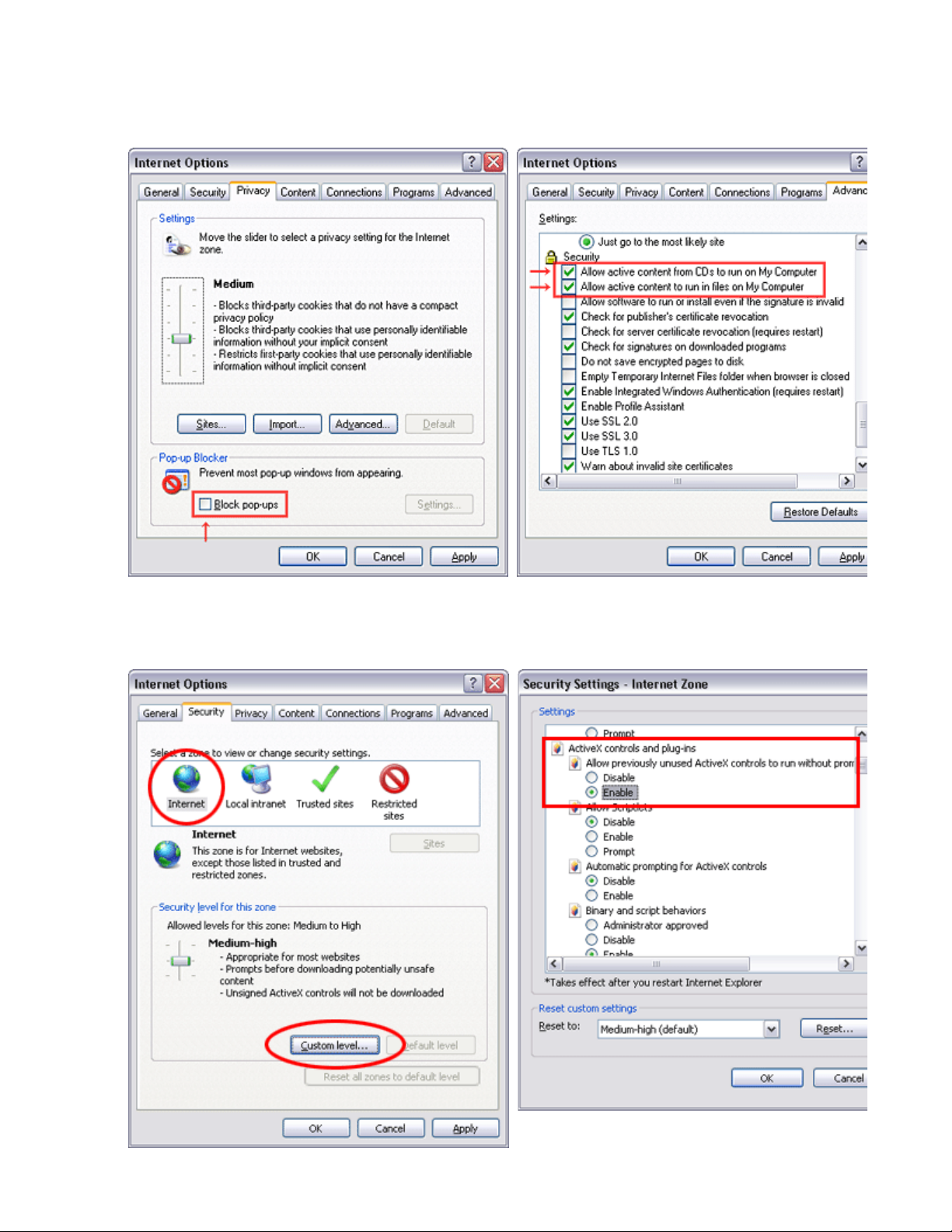
2. Internet Explorer setting
[Tools] - [Internet Options]
for Internet Explorer 7
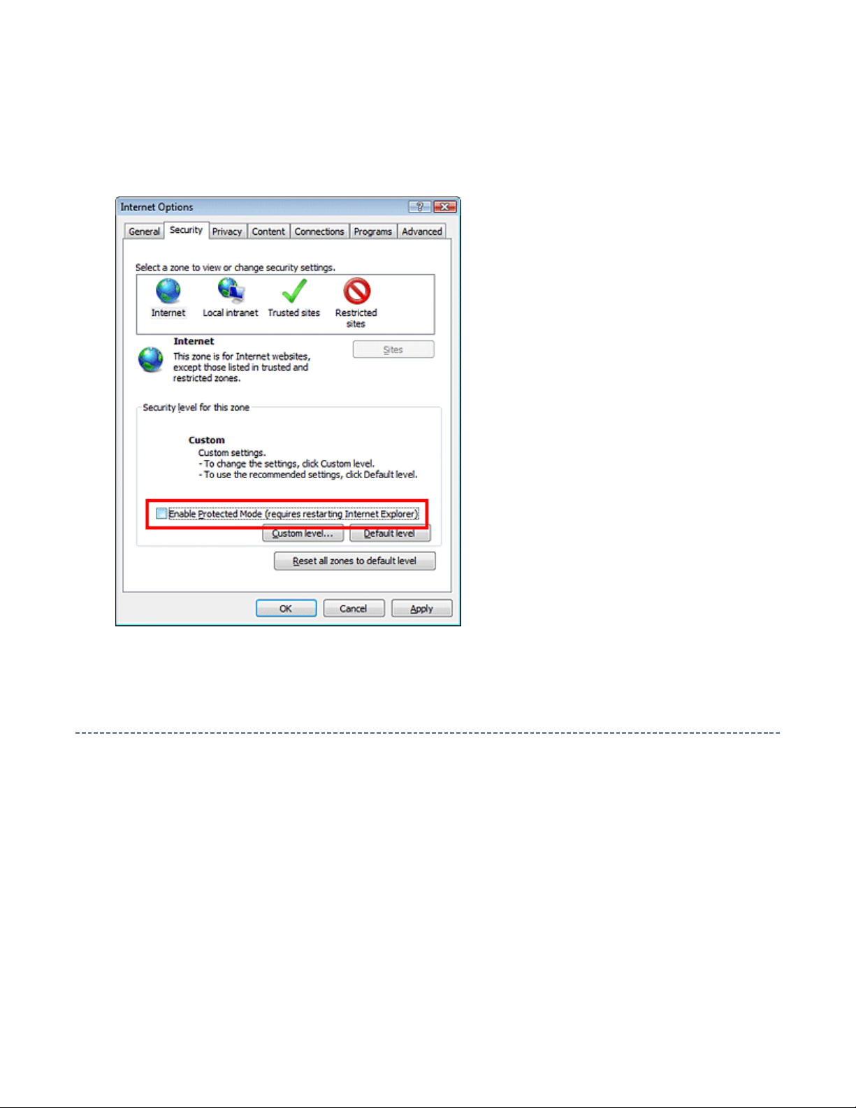
for Windows Vista
Operating Environment
PC : Pentium III or higher recommended
Monitor : 1024 x 768 or higher resolution recommended
Mouse : A mouse with wheel recommended
OS : Microsoft Windows 2000 SP4 / XP / Vista
Browser :
Drawing viewer : Autodesk DWF Viewer 6.0 / 7.0
* Use the software following respective license terms and conditions.
Microsoft Internet Explorer 6.0 / 7.0

Functions Provided on Each Drawing Page
When the character string of a part on the drawing is clicked, its information is popped up at the location.
You can get any parts information immediately on the screen without referring to the maintenance parts list.
You can search any part within the displayed drawing or within the whole schematic diagram/board view by
up window displayed by clicking a part 's character string allows to
signal is searched and the display changes to the destination. Connecter destinations can also be searched in
When two or more search results are provided, their drawing names are displayed, allowing you to choose a
When any of the color buttons on the toolbar is clicked, it can be selected to display desired layer in its color
The Autodesk DWF Viewer enables to print the displayed drawing region as it is on a printer. It also allows
Parts Information Reference Function
Parts Search Function
specifying a location number. The popsearch the part within the applicable schematic diagram, board view or spare parts list.
A circle appears when the part is found, showing the part's location within the drawing.
Signal Line/Connector Destination Display Function
When a name at the end of a signal line in a divided schematic diagram is clicked, the destination of the
the same way.
desired drawing to display.
Layer Display Changing Function
or not to display each layer. This allows you to see the pattern layer only by setting other layers to "nondisplay".
PC Board View Pattern Highlighting Function
When a pattern on a board view is clicked, it is highlighted in green. This allows easy pattern tracing.
Specified Area Printing Function
to print a large-sized drawing in multiple pieces (tile printing).

path names written on the source files of each
Create the appropriate folder where the ZEUS Engine Program Ver.2 and the ZEUS Service Manual
Using with Network
PRECAUTION
To use ZEUS Service Manual Ver.2 with network, the file-
ZEUS Engine Program Ver.2 and ZEUS Service Manual Ver.2 are to be modified.
Perform the procedure described below.
Preparation
1. Run the program file zuesFPch.exe to install the program file for File-Path to the Local PC.
-> Download zeusFPch_setup.zip (2.3MB)
2. Run the program file ZeusSetup_v2.0.exe to install the ZEUS Engine Program in C:\Program
Files\zeus of the local PC. This can be done by running the installer program provided.
3.
Ver.2 to be stored in the server.
4. Move the ZEUS Engine Program of step 2 to the folder created at step 3 in the Server.
5. Detach the ZEUS Service Manual Ver.2 to the folder created at step 3 in the Server.
6. Unzip the ZEUS Service Manual Ver.2 within the folder in the Server.
Example of folder
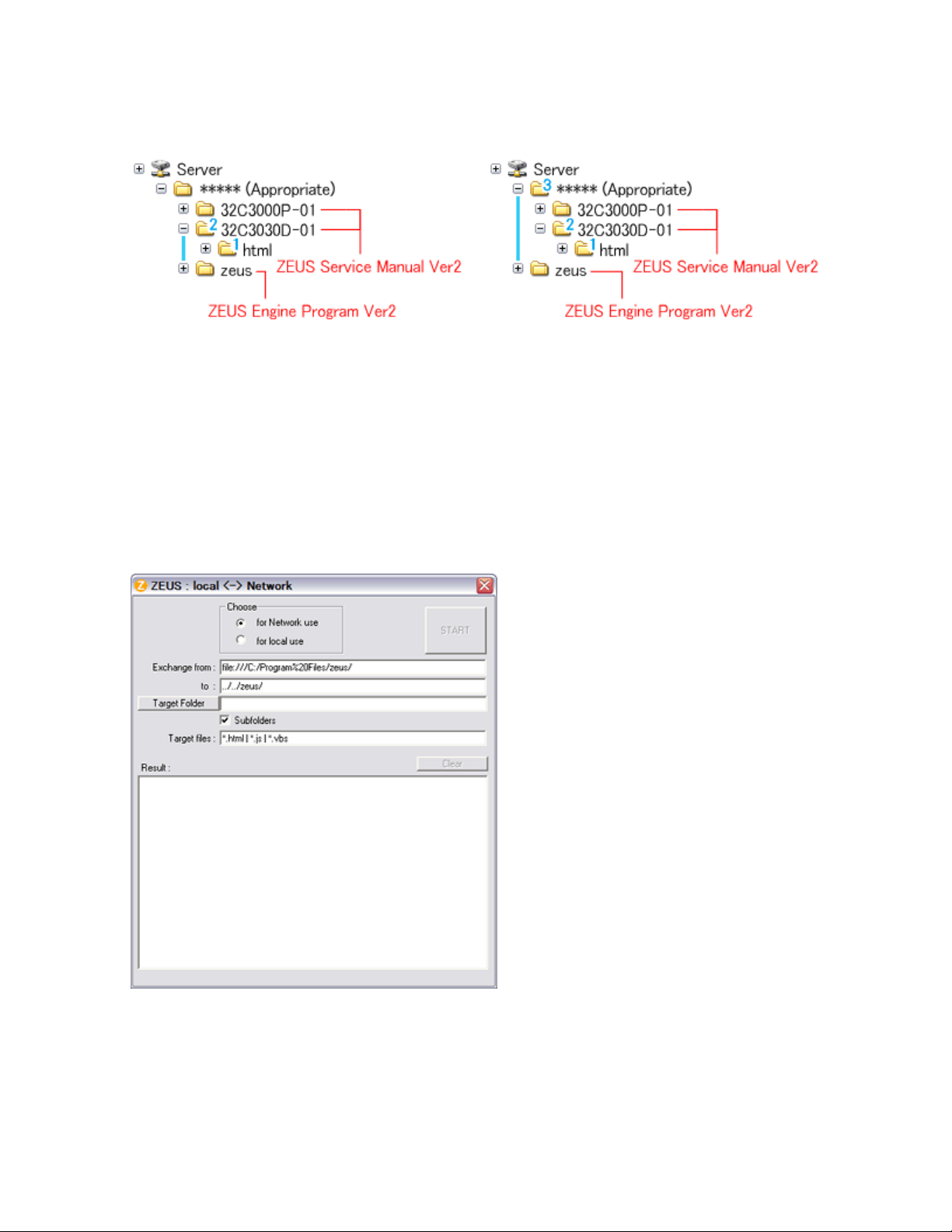
path names written in both source files of ZEUS
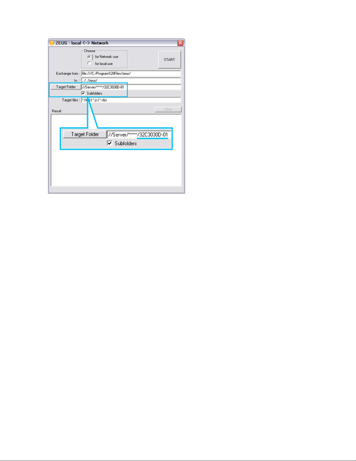
path of both ZEUS Engine Program and ZEUS Service Manual to use with
network, pay the attention to set the "Exchange to" column that should have a proper relation between
Procedure of File-Path
The zeusFPch is the exclusive program to exchange the file-
Manual and ZEUS Engine program into those applicable to the network use.
1. Whenever changing the file-
ZEUS Engine Program and ZEUS Service Manual with referring the following.
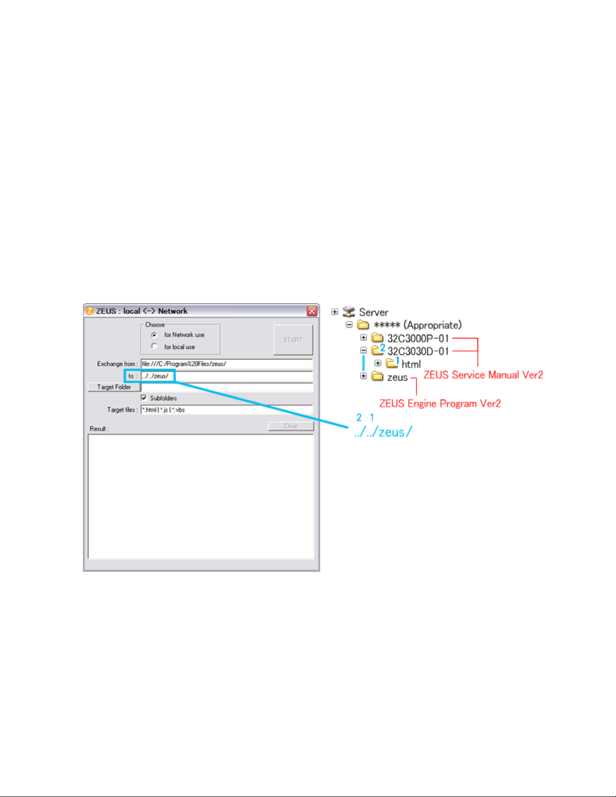
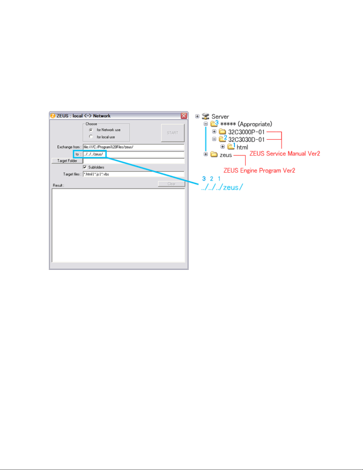
Run the zeusFPch and set "Exchange to" by referring to the examples below.
In the "Exchange to" column shows the relation between ZEUS Service Manual and ZEUS Engine
Example 1 :
Program.
../ counts the relation between.
Thus in this case, it must be ../../zeus/ (2 counts).
Example 2 :
In this case, it must be ../../../zeus/ (3 counts).
Set ZEUS Engine Program in the created folder in the server to the "Target Folder", and then press
2. Run the zeusFPch to change the path in the ZEUS Engine Program Ver.2.
3.
"START".
(This procedure is one time only)
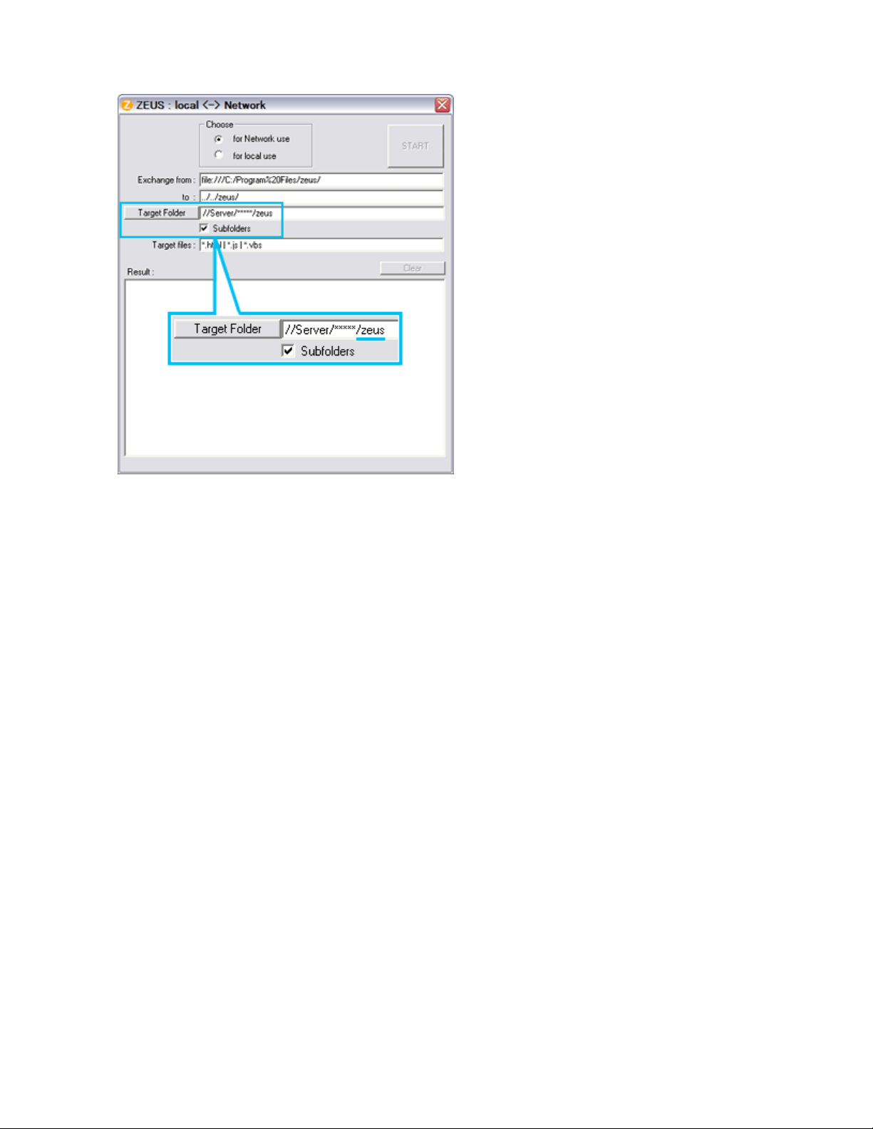
Set unzipped ZEUS Service Manual in the created folder in the server to the "Target Folder", and then
4. Run the ZeusFPch to change the path in the ZEUS Service Manual Ver2.
5.
press "START".
(This procedure is required whenever placing service manual.)
bottom corner on the screen whenever searching the location links. This is not malfunction.
Confirmation
Confirm that service manual on the server can be operated normally by client PC.
Note:
In case of accessing the ZEUS Manual through WEB site, the small pop-up window appears at the left
IMPORTANT NOTICE
Through WEB, ver. 6.5 has been released but with it, the linking function in this manual may
A Known Malfunction
Autodesk® DWF™ Viewer version
(Free software provided through WEB)
Use Autodesk DWF Viewer ver. 6.0.
not work properly.
If ver. 6.5 has been installed, uninstall it and reinstall ver. 6.0.
To get ver. 6.0, click the icon, or contact to the nearest Toshiba Service Centre for further
assistance.
Freezing windows opened
(Cannot close the open windows)
This may happen occasionally.
In case of encountering this, follow the procedure below.
1. Press [Ctrl], [Alt] and [Delete] keys at the same time to engage windows security
windows.
2. Then, choose TASK manager and Application tab, and select TOSHIBA SERVICE
MANUAL-Microsoft Internet Explorer.
3. Click TASK-end.
Main Window back forwarded

The real cause has not been found yet but with this condition, nothing disturbs the service
manual operation.
Continue to use by operating the windows.
Precaution when opening the diagrams
While opening the diagrams, the menu in the left frame changes its color to GRAY. This is
an indication that the viewer is processing.
With this condition, the menu indication color may stick to the GRAY color or Windows
may freeze if clicking other menu.
To avoid such things, do not operate any others while menu turns GRAY color.
If entering this, re-open the service manual or refresh the left frame.

GREEN PRODUCT PROCUREMENT
prohibit any marketing of new products containing the restricted substances.
Corporation recognizes environmental protection as a key management tasks, and is doing its
products, parts and materials that have low environmental impacts.
The EC is actively promoting the WEEE & RoHS Directives that define standards for
recycling and reuse of Waste Electrical and Electronic Equipment and for the Restriction of
the use of certain Hazardous Substances. From July 1, 2006, the RoHS Directive will
Increasing attention is given to issues related to the global environmental. Toshiba
utmost to enhance and improve the quality and scope of its environmental activities. In line
with this, Toshiba proactively promotes Green Procurement, and seeks to purchase and use
Green procurement of parts is not only confined to manufacture. The same green parts used
in manufacture must also be used as replacement parts.

LEAD-FREE SOLDER
free solder must
be used in the servicing and repair of this product.
product made with lead
free solder may result in damage to the component and or PCB being
product especially when soldering large components, through
This product is manufactured using lead-free solder as a part of a movement within the
consumer products industry at large to be environmentally responsible. Lead-
WARNING: This product is manufactured using lead free solder.
DO NOT USE LEAD BASED SOLDER TO REPAIR THIS PRODUCT!
The melting temperature of lead-free solder is higher than that of leaded solder by 86ºF to
104ºF (30ºC to 40ºC). Use of a soldering iron designed for lead-based solders to repair
-
soldered. Great care should be made to ensure high-quality soldering when servicing this
-hole pins, and on PCBs as the
level of heat required to melt lead-free solder is high.
SAFETY INSTRUCTION
Always keep tools, components of the product, etc away from the children, These items
WARNING: BEFORE SERVICING THIS CHASSIS, READ THE "SAFETY
PRECAUTION" AND "PRODUCT SAFETY NOTICE" INSTRUCTIONS BELOW.
Safety Precaution
WARNING: SERVICING SHOULD NOT BE ATTEMPTED BY ANYONE
UNFAMILIAR WITH THE NECESSARY PRECAUTIONS ON THIS RECEIVER.
THE FOLLOWING ARE THE NECESSARY PRECAUTIONS TO BE OBSERVED
BEFORE SERVICING THIS CHASSIS.
1. An isolation transformer should be connected in the power line between the receiver
and the AC line before any service is performed on the receiver.
2. Always disconnect the power plug before any disassembling of the product. It may
result in electrical shock.
3. When replacing a chassis in the cabinet, always be certain that all the protective
devices are put back in place, such as nonmetallic control knobs, insulating covers,
shields, isolation resistor-capacitor network, etc.
4.
may cause injury to children.
5. Depending on the model, use an isolation transformer or wear suitable gloves when
servicing with the power on, and disconnect the power plug to avoid electrical shock
when replacing parts. In some cases, alternating current is also impressed in the
chassis, so electrical shock is possible if the chassis is contacted with the power on.

6. Always use the replacement parts specified for the particular model when making
NEVER remodel the product in any way. Remodeling can result in improper operation,
repairs. The parts used in products require special safety characteristics such as
inflammability, voltage resistance, etc. therefore, use only replacement parts that have
these same characteristics. Use only the specified parts when the mark is indicated
in the circuit diagram or parts list.
7. Parts mounting and routing dressing of wirings should be the same as that used
originally. For safety purposes, insulating materials such as isolation tube or tape are
sometimes used and printed circuit boards are sometimes mounted floating. Also make
sure that wirings is routed and clamped to avoid parts that generate heat and which use
high voltage. Always follow the manufactured wiring routes / dressings.
8. Always ensure that all internal wirings are in accordance before re-assembling the
external casing after a repairing completed. Do not allow internal wiring to be pinched
by cabinets, panels, etc. Any error in reassembly or wiring can result in electrical
leakage, flame, etc., and may be hazardous.
9.
malfunction, or electrical leakage and flame, which may be hazardous.
10. Touch current check. (After completing the work, measure touch current to prevent an
electric shock.)
Plug the AC cord directly into the AC outlet. Do NOT use an isolation transformer
for this check.
Connect a measuring network for touch currents between each exposed metallic part
on the set and a good earth ground such as a water pipe.
Annex D
(normative)
Measuring network for TOUCH CURRENTS
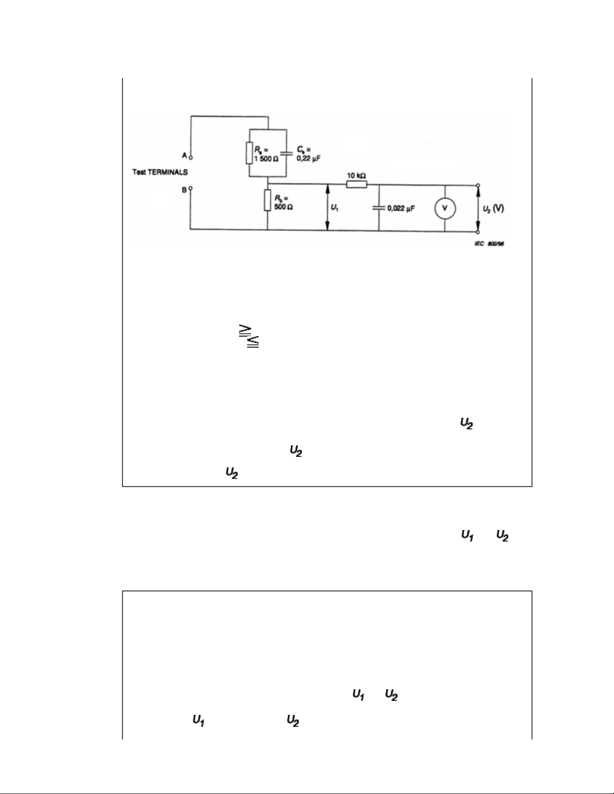
Resistance values in orms (Ω).
V: Voltmeter or oscilloscope
(r.m.s. or peak reading)
Input resistance : 1 MΩ
Input capacitance : 200 pF
Frequency range : 15 Hz to 1 MHz and d.c. respectively
Note: Appropriate measures should be taken to obtain the correct value in case of non
sinusoidal waveforms.
The measuring instrument is calibrated by comparing the frequency factor of with the
solid line in figure F.2 of IEC 60990 at various frequencies. A calibration curve is
constructed showing the deviation of from the ideal curve as a function of frequency.
TOUCH CURRENT = /500 (peak value).
The potential at any point (TOUCH CURRENT) expressed as voltage and
does not exceed the following value:
The part or contact of a TERMINAL is not HAZARDOUS LIVE if:
a) The open-circuit voltage should not exceed 35 V (peak) a.c. or 60 V d.c. or, if a) is not
met.
b) The measurement of the TOUCH CURRENT shall be carried out in accordance with
IEC 60990, with the measuring network described in Annex D of this standard.
The TOUCH CURRENT expressed as voltages and , does not exceed the
following values:
- for a.c. : = 35 V (peak) and = 0.35 V (peak);
- for d.c. : = 1.0 V
Note: The limit values of = 0.35 V (peak) for a.c. and = 1.0 V for d.c. correspond to
the values 0.7 mA (peak) a.c. and 2.0 mA d.c.
Product Safety Notice
Many electrical and mechanical parts in this chassis have special safety-related
characteristics. These characteristics are often passed unnoticed by a visual inspection and
the protection afforded by them cannot necessarily be obtained by using replacement
components rated for higher voltage, wattage, etc. Replacement parts which have these
special safety characteristics are identified in this manual and its supplements; electrical
components having such features are identified by the international hazard symbols on the
schematic diagram and the parts list.
Before replacing any of these components, read the parts list in this manual carefully. The
use of substitute replacement parts which do not have the same safety characteristics as
specified in the parts list may create electrical shock, fire, or other hazards.
SAFETY INSTRUCTION
should enter the mouth, rinse the mouth thoroughly with water. If the fluid should contact the
When attaching the LCD module to the LCD cover, position it appropriately and fasten
Handling the LCD Module
Safety Precaution
In the event that the screen is damaged or the liquid crystal (fluid) leaks, do not breathe in or
drink this fluid.
Also, never touch this fluid. Such actions could cause toxicity or skin irritation. If this fluid
skin or clothing, wipe off with alcohol, etc., and rinse thoroughly with water. If the fluid
should enter the eyes, immediately rinse the eyes thoroughly with running water.
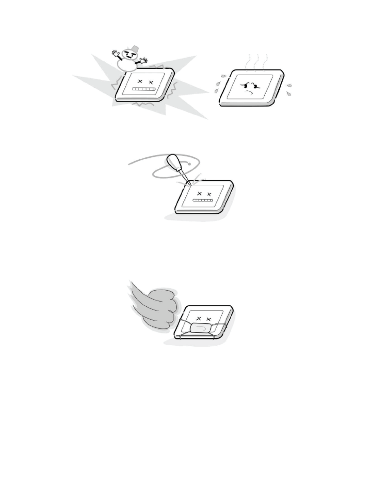
Precautions for Handling the LCD Module
CAUTION: The metal edges of the LCD module are sharp, handle it with
care.
The LCD module can easily be damaged during disassembly or reassembly; therefore,
always observe the following precautions when handling the module.
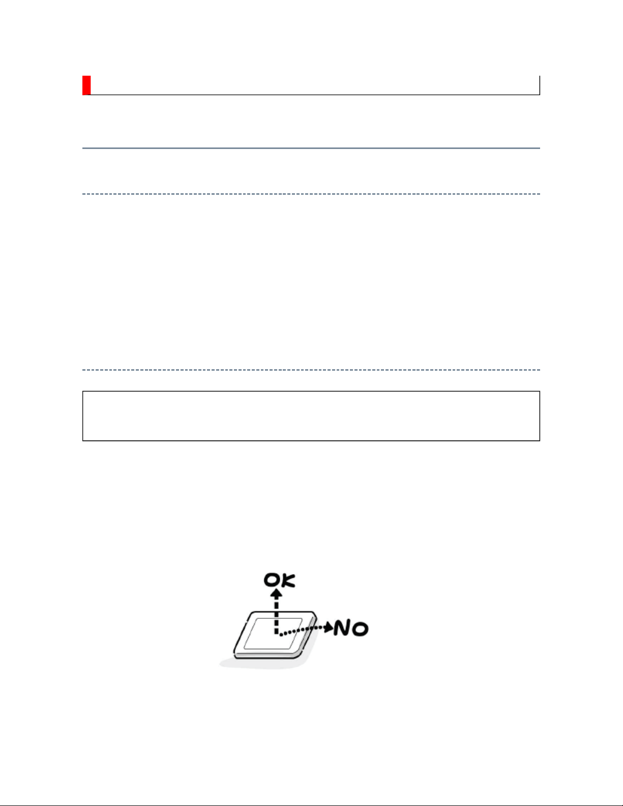
1.
at the position where the display can be viewed most conveniently.
2. Carefully align the holes at all four corners of the LCD module with the corresponding
holes in the LCD cover and fasten with screws. Do not strongly push on the module
because any impact can adversely affect the performance. Also use caution when
handling the polarized screen because it can easily be damaged.
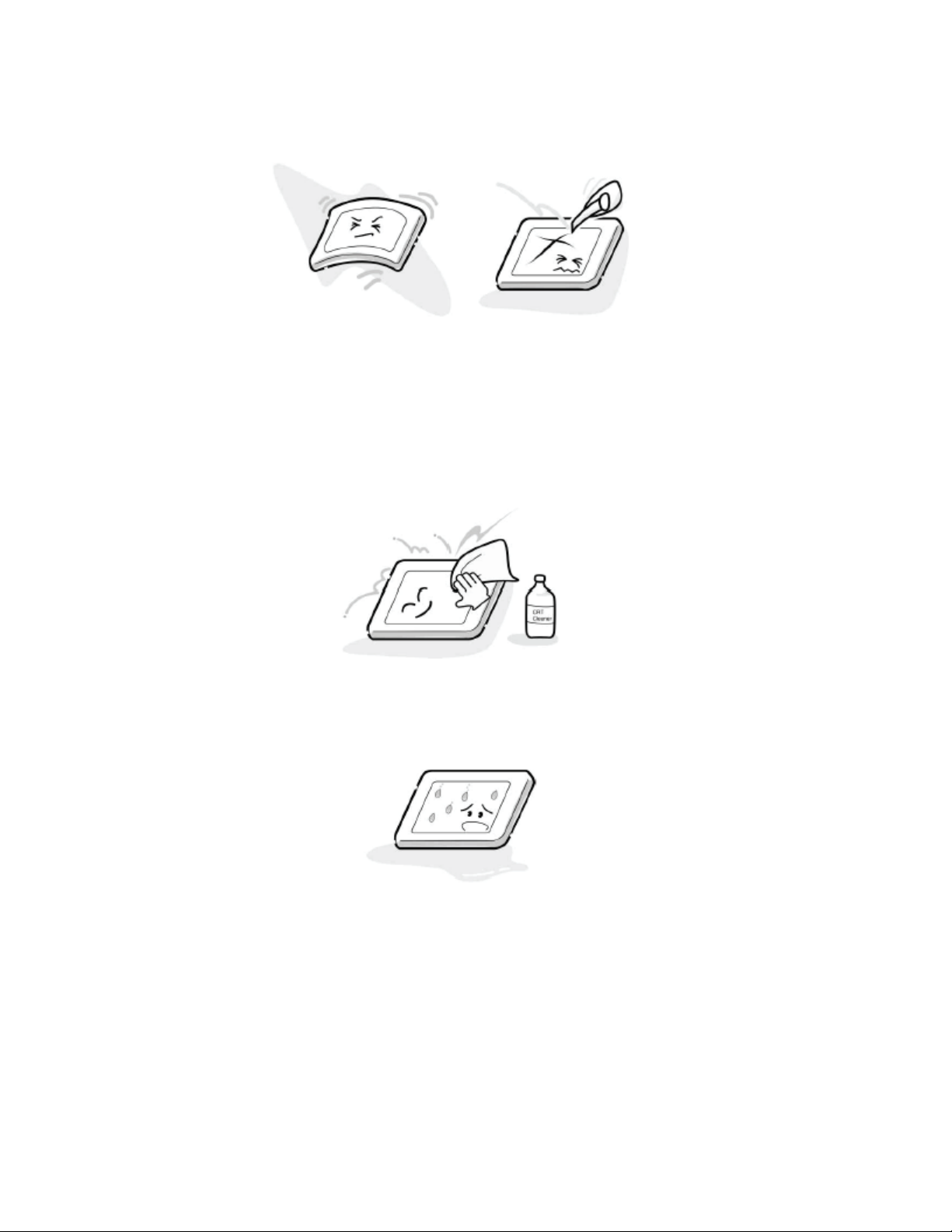
3. If the panel surface becomes soiled, wipe with cotton or a soft cloth. If this does not
remove the soiling, breathe on the surface and then wipe again.
If the panel surface is extremely solied, use a CRT cleaner as a cleaner. Wipe off the
panel surface by drop the cleaner on the cloth. Do not drop the cleaner on the panel.
Pay attention not to scratch the panel surface.
4. Leaving water or other fluids on the panel screen for an extended period of time can
result in discoloration or stripes. Immediately remove any type of fluid from the screen.
5. Glass is used in the panel, so do not drop or strike with hard objects. Such actions can
damage the panel.
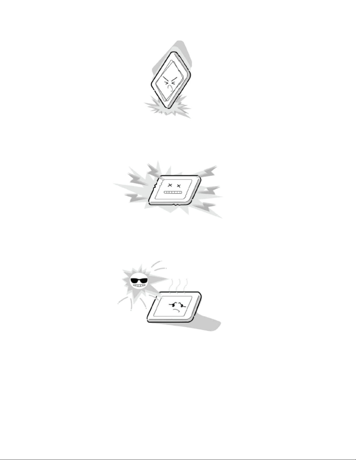
6. CMOS-LSI circuitry is used in the LCD module, so avoid damage due to static
electricity. When handling the module, use a wrist ground or anchor ground.
7. Do not expose the LCD module to direct sunlight or strong ultraviolet rays for an
extended period of time.
8. Do not store the LCD module below the temperature conditions described in the
specifications. Failure to do so could result in freezing of the liquid crystal due to cold
air or loss of resilience or other damage.
9. Do not disassemble the LCD module. Such actions could result in improper operation.
10. When transporting the LCD module, do not use packing containing epoxy resin
(amine) or silicon resin (alcohol or oxim). The gas generated by these materials can
cause loss of polarity.
U06A
KEY
U05A
MAIN (DIGITAL)
POWER
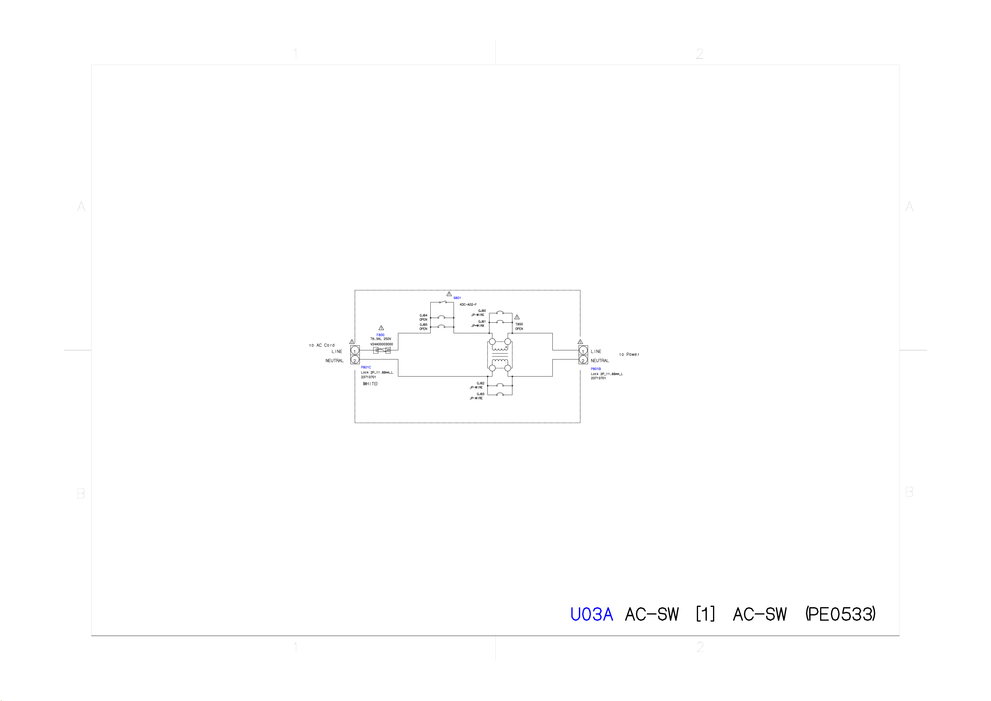
U03A
AC SW
U04A LED
U04B RMT
Non
UAR
T
REQ
I2C
HDM
I
HDMI3
S
I
F
ATV(V
)
REMOTE
OUT
HDMI2
HDMI1
SPDIF
12V
RECEIVER
OPTICAL
SENSOR
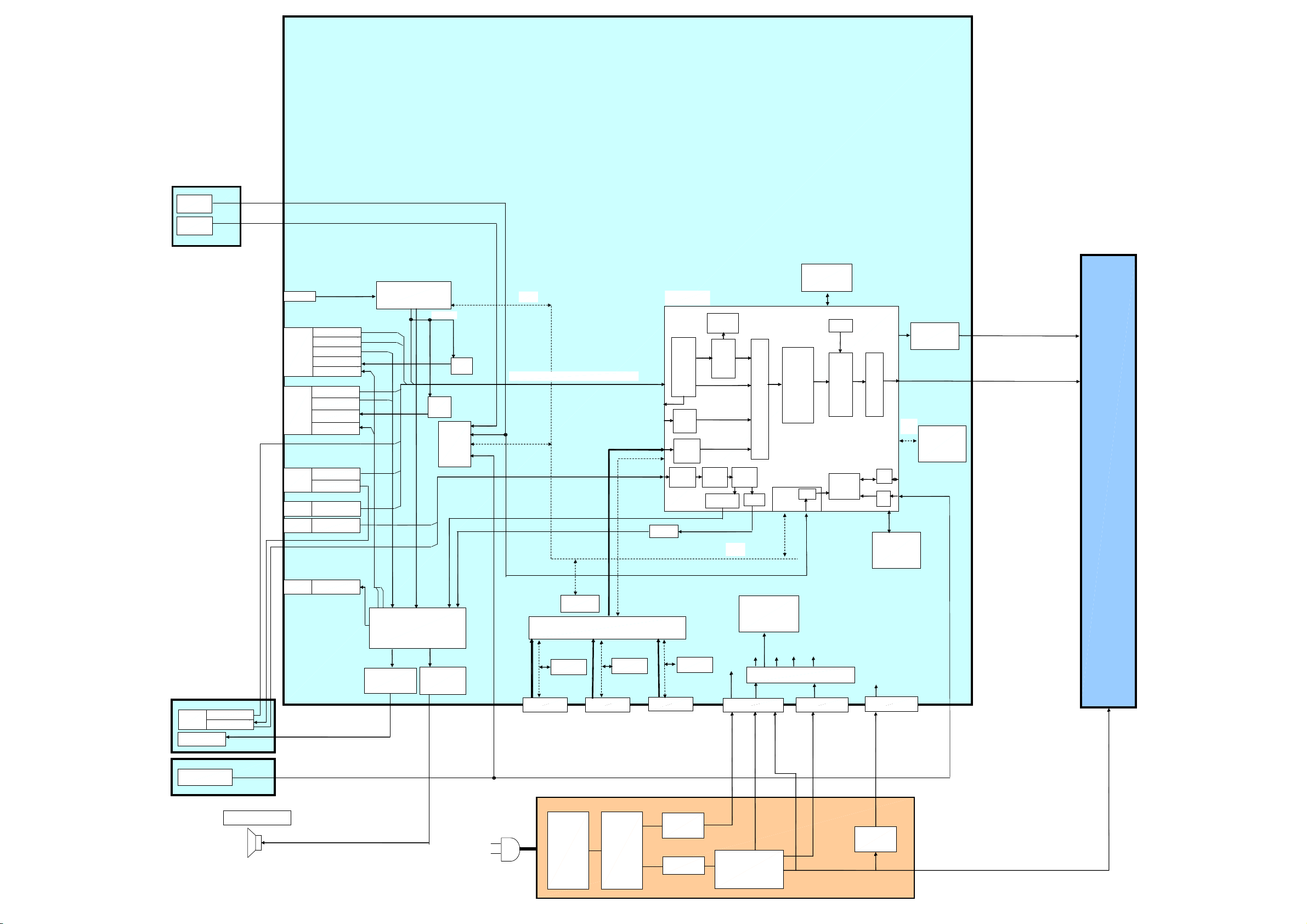
MAIN BOARD
RF
CVBS
R/G/B/FB
EXT1
LR
(SCART)
TVOUT V
TVOUT L/R
CVBS/S(Y/C)
LR
EXT2
(SCART)
TVOUT V
TVOUT L/R
TIF
75ohm
Driver
75ohm
Driver
Standby
uCON
CVBS/RGBFB/SY/SC/(Y/Cb/ Cr) or (RGBHV)
656
FLI32626
Sequoia
Analog
Front
End
(16port)
Digital
Input A
HDMI
VBI Data
Processor
Video
Decoder
MUX
DDRII RAM*2
DCDi
MADi
Scaling
OSD
BEP
LCD
PANEL
TCON
PANEL I/F
LVDS
I2C
EEPROM
CVBS/S(Y/C)
EXT3
(FRONT)
L/R
Headphone (L/R)
TACT
KEY
EXT3
(REAR)
EXT7
PC
AUDIO
Y/Cb/Cr
L/R
R/G/B/H/V
L/RPC/HDMI
L/R
HP AMP
MTS+
APRO
MSP
AUDIO AMP
Bt601 8Bit
HD,VD,CLK
EXT4
EDID
ROM
KEY
ROM
SW
EXT5
HDMI
EDID
ROM
ADC
YCbCr 16bit
AMP
EXT6
EDID
ROM
Audio
Mux
I2S
I2C
5V1
Audio
DSP
DAC
Regulator
P811B
Sequoia
5V2D
32V
5V2
12V
Low
IR I/F
Power
Monitor
VCC AUDIO
9V
LOWB Regulator
P811C
Micro-
processor
18V AUDIO
GPIO
ADC
SPI SERIAL
FLASH ROM
12V_ LCD
P810B
24V
POWER BOARD
SPEAKER (L/R)
Standby
5V1
18V_AUDIO
POWER
AC INPUT
PFC
CIRCUIT
HIC
CONVERTER
TRANS
24V
12V_LCD
12V_LCD
REG
SCHEMATIC DIAGRAM
Precaution
WARNING: BEFORE SERVICING THIS CHASSIS, READ THE "X-RAY
RADIATION PRECAUTION" FOR DIRECT VIEW CTV ONLY, "SAFETY
PRECAUTION" AND "PRODUCT SAFETY NOTICE" OF THIS MANUAL.
CAUTION: The international hazard symbols " " in the schematic diagram
and the parts list designate components which have special characteristics
important for safety and should be replaced only with types identical to
those in the original circuit or specified in the parts list.
The mounting position of replacements is to be identical with originals.
Before replacing any of these components, read carefully the SAFETY
PRECAUTION and PRODUCT SAFETY NOTICE.
Do not degrade the safety of the receiver through improper servicing.
Note:
1. RESISTOR
Resistance is shown in ohm [K=1,000, M=1,000,000]. All resistors are 1/6 W and 5 %
tolerance carbon resistor, unless otherwise noted as the following marks.
1/2R : Metal or Metal oxide of 1/2 watt
1/2S : Carbon composition of 1/2 watt
1RF : Fuse resistor of 1 watt
10 W : Cement of 10 watt
K : ±10 %
G : ±2 %
F : ±1 %
2. CAPACITOR
Unless otherwise noted in schematic, all capacitor values less than 1 are expressed in
Electrolytic capacitor
µF, and the values more than 1 in pF.
All capacitors are ceramic 50 V, unless otherwise noted as the following marks.
=
= Mylar capacitor
3. The parts indicated with " " have special characteristics, and should be replaced with
identical parts only.
4. Voltages read with DIGITAL MULTI-METER from point indicated to chassis ground,
using a color bar signal with all controls at normal, line voltage at nominal AC volts.
5. Waveforms are taken receiving color bar signal with enough sensitivity.
6. Voltage reading shown are nominal values and may vary ±20 % except H.V.
 Loading...