

TOSHIBA 32C3005P Service Manual
ADJUSTMENT
Service Mode
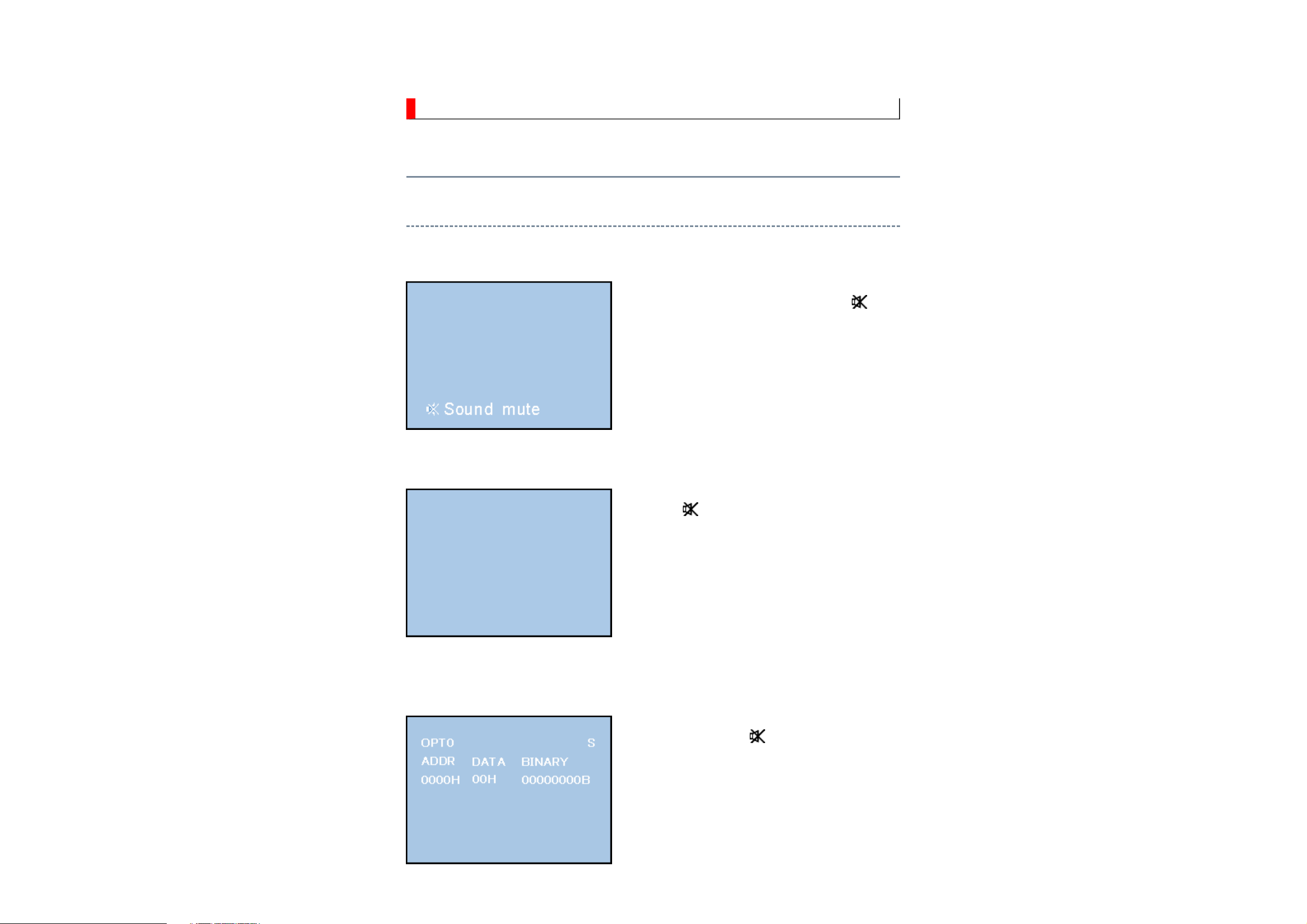
Entering to Service Mode
1. Set VOLUME to minimum and press
button once on remote control.
↓
↓
Service Mode display
2. Press button again and hold button down.
3. While holding the button, press MENU
button on TV set.
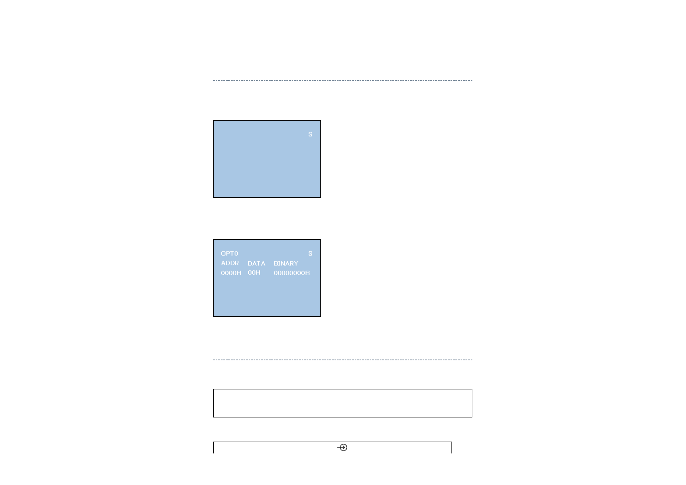
Displaying the Adjustment Menu
Press MENU button on TV.
Service Mode
Press ↑ ↓ Press
Adjustment Mode
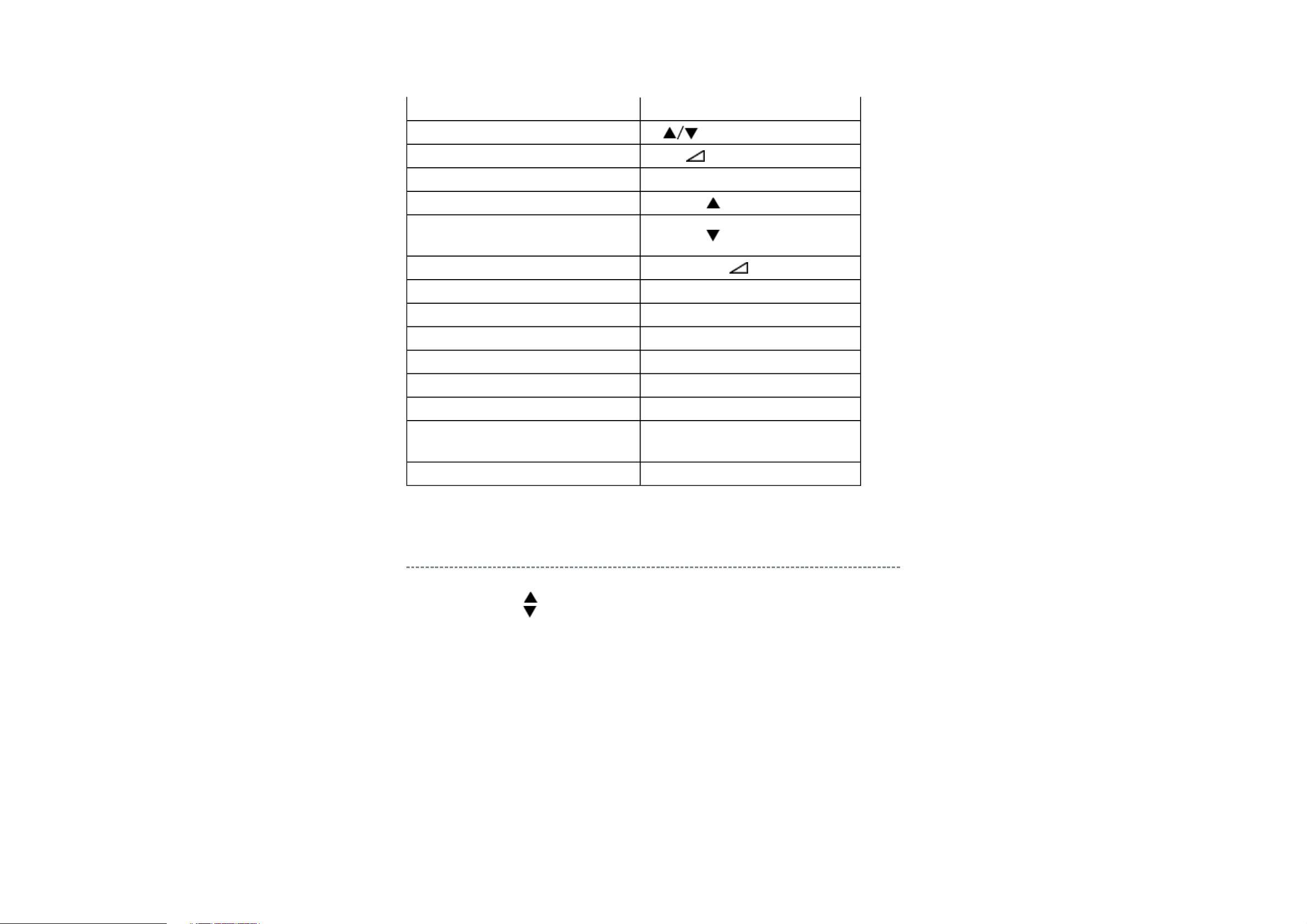
Key Function in the Service Mode
The following key entry during display of adjustment menu provides special functions.
CAUTION: Never try to perform initialization unless you have changed the
memory IC.
button (on remote control)
Never adjust H.POS and V.POS except PAL/WIDE mode.
Test signal selection
Selection of the adjustment items
Change of the data value
Adjustment menu mode ON/OFF MENU button (on TV)
Initialization of the memory (QA02)
Reset the count of operating
protect circuit to "00"
Turn off I2C bus communication
"RCUT" selection 1 button
"GCUT" selection 2 button
"BCUT" selection 3 button
"CNTX" selection 4 button
"COLC" selection 5 button
"UVTT" selection 6 button
Automatic A/D Adjustment
(PC, Component, Composite (PAL, NTSC))
CH (on TV or remote control)
Volume +/- (on TV or remote control)
CALL + CH button on TV
CALL + CH button on TV
CALL + Volume + button on TV
7 button
Self diagnostic display ON/OFF 9 button
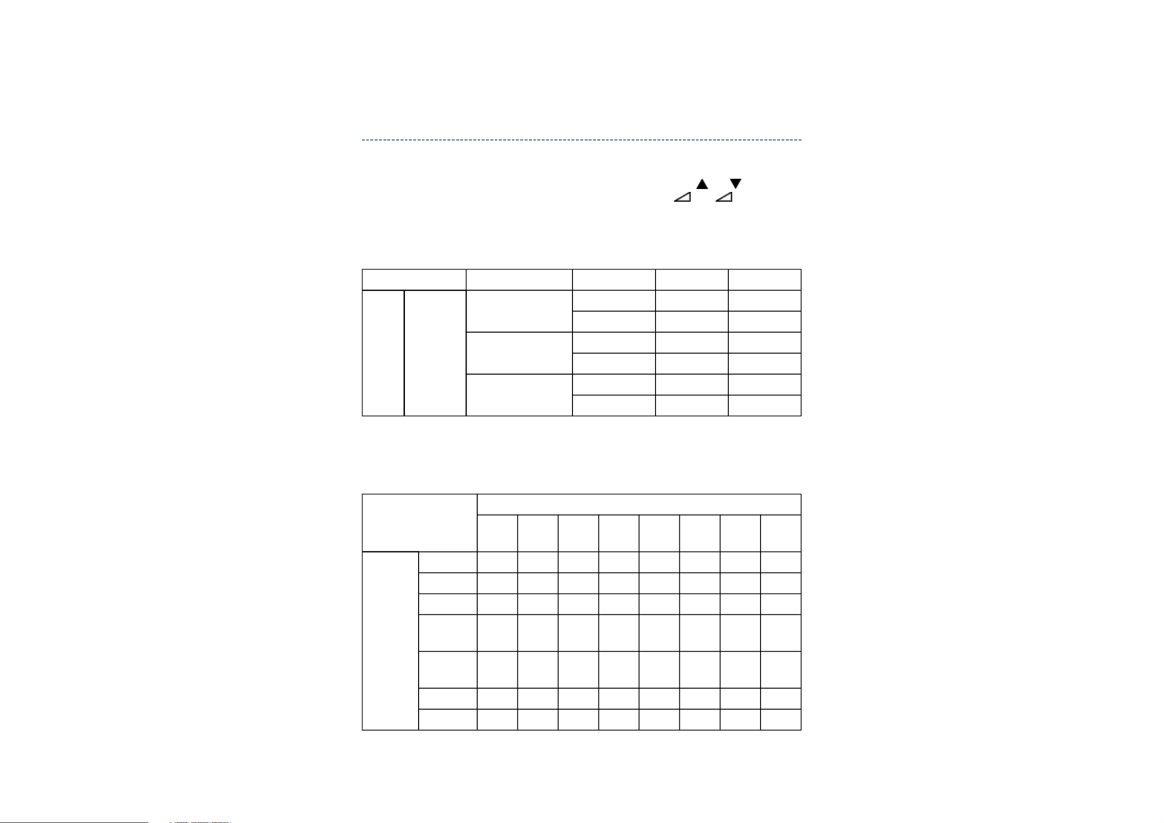
Selecting the Adjusting Item
Every pressing of CH button in the service mode changes the adjustment items in the
order of table below. ( button for reverse order)
SETTING & ADJUSTING DATA
[ SERVICE MODE ]
ADJUSTING ITEMS AND DATA IN THE SERVICE MODE:
Note:
The image system data of RCUT-BDRV is different by each image format.
The PAL value is indicated in the table.

Item Name of adjustment
RCUT R CUT OFF
GCUT G CUT OFF
BCUT B CUT OFF
RDRV R DRIVE
GDRV G DRIVE
BDRV B DRIVE
BRTC BRIGHTNESS CENTER
COLC COLOR CENTER
UVTT BASE BAND TINT
CNTX CONTRAST MAX
VOLUX MAX VOLUME LIMITED
PLLW0 PLL WAIT TIME
PLLW1 PLL WAIT TIME
PLLW2 PLL WAIT TIME
PLLW3 PLL WAIT TIME
PLLW4 PLL WAIT TIME
PLLW5 PLL WAIT TIME
OPT1 TV SET OPTION 1
OPT2 TV SET OPTION 2
OPT3 TV SET OPTION 3
OPT4 TV SET OPTION 4 (PANEL OPT DATA FOR VENDOR)
OPT5 TV SET OPTION 5 (PANEL OPT DATA FOR SIZE)
OPT6 TV SET OPTION 6 (HOTEL MODE)
OPT7 TV SET OPTION 7 (HOTEL MODE)
OPT8 TV SET OPTION 8 (HOTEL MODE)
TVOP TV SET OPTION
ID MODEL ID
BDWID BORDER WIDTH FOR EXACT SCAN
BDHIT BORDER HEIGHT FOR EXACT SCAN
FPLG MASK_ENABLE (SD/HD)
FPLG2 Channel LOGO Vector Clip SW (SD)

FPLG3 Channel LOGO Vector Clip SW (HD)
Factory preset data will be loaded after setting Model ID data.
(Refer to Initialization of Memory Data of QA02 and setting data of signal board.)
Adjusting the Data
Pressing of VOLUME +/- button will change the value of data in the range from 00H to
FFH. The variable range depends on the adjusting item.
I2C Bus Off
Turn off I2C communication between IC700 and IC400.
1) Press and hold the CALL button on the remote control, then press the Volume
+ button on the TV.
2) Display "BUS Off" OSD.
3) I2C communication turned off.
Note:
To return Bus on status, press and hold the CALL button on the remote control, then press
the Volume + button on the TV again. TV will be turned off and automatically turned
on, then status will be Bus On.
Setting TVOP
Enter to service mode and select menu of TVOP by pressing P or P during display of
adjustment menu. After selecting TVOP, press + or - to set I2C check function to
disable or enable as below.
TVOP FUNCTION DESCRIPTION 1 0 (Normal)
D5 (bit5) I2C check between IC700 and IC400. (WDT) Disable Enable
Setting Panel Option Data
Panel option data is subject to OP4 and OP5.
Enter to service mode and select menu of OPT4 or OPT5 by pressing P or P during
display of adjustment menu. After selecting OPT4 or OPT5, press + or - to set OPT4
or OPT5 value as table below.
Panel option data
Series Model name Panel vendor OPT4 value OPT5 value
C3500 EU Ready 32C3500P/3502P/
3005P/3006P
37C3500P/3502P/
3005P/3006P
42C3500P/3502P/
3005P/3006P
IPS 0x07 0x05
LPL 0x01 0x05
IPS 0x07 0x06
LPL 0x01 0x06
LPL 0x01 0x07
AUO 0x05 0x07
OP4
Ex. OPT4 value 0x05 indicates that panel vendor is AUO AMVA.
OPT4
Panel
vendor
LPL - - - - 0 0 0 1
SHP - - - - 0 0 1 0
D7
(bit7)
D6
(bit6)
D5
(bit5)
D4
(bit4)
D3
(bit3)
D2
(bit2)
D1
(bit1)
D0
(bit0)
OP5
CMO - - - - 0 0 1 1
AUO
- - - - 0 1 0 0
PMVA
AUO
- - - - 0 1 0 1
AMVA
SAMSUNG - - - - 0 1 1 0
IPS - - - - 0 1 1 1

Ex. OPT5 value 0x05 indicates that panel size is 32.
OPT5
Size 32 - - - - 0 1 0 1
37 - - - - 0 1 1 0
42 - - - - 0 1 1 1
D7
(bit7)
D6
(bit6)
D5
(bit5)
D4
(bit4)
D3
(bit3)
D2
(bit2)
D1
(bit1)
(bit0)
Convert from Bit (Binary) to Hex
The table for converting from bit (D7-D0) to hex (0x**).
BIT (Binary)
High nibble D7 D6 D5 D4
Low nibble D3 D2 D1 D0
D0
HEX 0 0 0 0 0
1 0 0 0 1
2 0 0 1 0
3 0 0 1 1
4 0 1 0 0
5 0 1 0 1
6 0 1 1 0
7 0 1 1 1
8 1 0 0 0
9 1 0 0 1
A 1 0 1 0
B 1 0 1 1
C 1 1 0 0
D 1 1 0 1
E 1 1 1 0
F 1 1 1 1

E.g. If Bit D7-0 = 0101 1010, Hex data is 0x5A.
Exit from Service Mode
Pressing POWER button to turn off the TV once.
Initialization of Memory Data of QA02 and Setting Data of Signal Unit
After replacing QA02 or signal board, the following initialization is required.
CAUTION: Never attempt to initialize the data unless QA02 has been
replaced.
Whenever using new signal board to the set, setting the Model ID data
according to Panel option data.
1) Enter the service mode.
2) Select menu of ID by pressing P or P during display of adjustment menu in the
service mode.
3) Change ID data into MODEL ID to initialize by pressing + or -, refer to table
below.
4) Press and hold the CALL button on the remote control, then press the CHANNEL
button on the TV.
5) Initialization progress dialog including model name and panel vendor is shown.
Progress status is "WRITING".
6) Progress status is changed "OK" and power cycle (automatically). Then QA02
initialization has been completed.
7) Enter the service mode and select version check mode. Confirm if model name and
model id set is correct. If not, repeat steps 1) to 6).

Note:
In case initialization by setting wrong MODEL ID is done, there is a possibility of
abnormal display.
8) Set I2C check function of TVOP to enable.
9) Check the picture carefully. If necessary, adjust any adjustment item above.
Perform "Auto tune" on the owner's manual.
MODEL ID (HEX) Model name Panel vendor
0x01 32C3500P/3502P/3005P/3006P IPS
0x02 32C3500P/3502P/3005P/3006P LPL
0x03 37C3500P/3502P/3005P/3006P IPS
0x04 37C3500P/3502P/3005P/3006P LPL
0x05 42C3500P/3502P/3005P/3006P LPL
0x06 42C3500P/3502P/3005P/3006P AUO
0x07
0x08
0x09
0x10
0x11
0x12
0x13
0x14
0x15
0x16
0x17
0x18
0x19
0x20
0x21
0x22
0x23
0x24
0x25
 Loading...