

Page 1

Equium™ 3100M
User's Manual
Model: 3100 Series
Copyright
This guide is copyrighted by Toshiba Corporation with all rights reserved. Under the copyright
laws, this guide cannot be reproduced in any form without the prior written permission of
Toshiba. No patent liability is assumed, however, with respect tothe use of the information
contained herein.
©
1999 by Toshiba Corporation. All rights reserved.
CD-ROM Safety Instruction
The CD-ROM drive employs alaser system. Toensure proper use of this product, please read this
instruction manual carefully and retain for future reference. Should the unit ever require
maintenance, contact an authorised service location.
Use of controls, adjustments or the performance of procedures other than those specified may
result in hazardous radiation exposure.
To prevent direct exposure tothe laser beam, donot try toopen the enclosure.
Notice
CLASS 1LASER PRODUCT
LASERSCHUTZKLASSE 1PRODUKT
TO EN60825
This appliance contains alaser system and is classified as a"CLASS 1LASER PRODUCT".
Touse this model properly, read the instruction manual carefully and keep this manual for your
future reference. In case of any trouble with this model, please contact your nearest
"AUTHORISED service station". Toprevent direct exposure tothe laser beam, donot try toopen
the enclosure.
USE OF CONTROLS OR ADJUSTMENTS OR PERFORMANCE OF PROCEDURES OTHER
THAN THOSE SPECIFIED IN THE OWNER'S MANUAL MAY RESULT IN HAZARDOUS
RADIATION EXPOSURE.
The information contained in this manual, including but not limited toany product specifications,
is subject tochange without notice.
TOSHIBA CORPORATION (TOSHIBA) PROVIDE NO WARRANTY WITH REGARD
TOTHIS MANUAL OR ANY OTHER INFORMATION CONTAINED HEREIN AND
HEREBY EXPRESSLY DISCLAIM ANY IMPLIED WARRANTIES OF
MERCHANTABILITY OR FITNESS FOR ANY PARTICULAR PURPOSE WITH
REGARD TOANY OF THE FOREGOING. TOSHIBA ASSUMES NO LIABILITY FOR
ANY DAMAGES INCURRED DIRECTLY OR INDIRECTLY FROM ANY TECHNICAL
OR TYPOGRAPHICAL ERRORS OR OMISSIONS CONTAINED HEREIN. IN NO
EVENT SHALL TOSHIBA BE LIABLE FOR ANY INCIDENTAL, CONSEQUENTIAL,
SPECIAL, OR EXEMPLARY DAMAGES, WHETHER BASED ONTORT, CONTRACT
OR OTHERWISE, ARISING OUT OF OR IN CONNECTION WITH THIS MANUAL OR
ANY OTHER INFORMATION CONTAINED HEREIN OR THE USE THEREOF.
Page 2

Trademarks
Equium is atrademark of Toshiba Corporation.
IBM and Wake onLAN are registered trademarks and PS/2 is atrademark of IBM Corporation.
MS-DOS, Microsoft, Windows and Windows NT are registered trademarks of Microsoft
Corporation.
Intel, LANDesk and Pentium are registered trademarks, andMMX is atrademark of Intel
Corporation.
3Com and the 3Com logo are registered trademarks of the 3Com Corporation.
CompuServe is aregistered trademark of CompuServe Interactive Services, Inc.
Ethernet is aregistered trademark of Xerox, Inc.
Magic Packet is atrademark of Advanced Micro Devices, Inc.
SoundBlaster Pro is atrademark of Creative Labs, Inc.
All other brand and product names are trademarks or registered trademarks of their respective
companies.
EU Declaration of Conformity
This product carries the CE-Mark in accordance with the related European Directives.
CE-Marking is the responsibility of Toshiba Europe, Hammfelddamm8, 41460 Neuss, Germany.
Page 3

Introduction
Congratulations onthe purchase of your high- performance Equium 3100Series computer.
The Equium 3100Series is build-to-order, micro- tower computer that offers the following
features:
q A high- performance, or 400MHz – 500MHz Intel® Celeron® processor withMMX™
Technology.
q Other processor speeds may be introduced as they are available
q 128 Kb of Level 2Cache
q Intel 810chipset
q 64 MB of SDRAM (expandable to512MB)
q Other configurations may be possible
q Intel 752graphic controller with 64-bit BitBLT accelerator
q Aureal 8810PCI 3D Audio System supporting 16-bit stereo, Windows Sound System and
Sound Blaster Pro®- compatible
q Ultra DMA 6GB IDE hard disk drive
q Other configurations may be possible
q A 40x IDE, ATAPI- compliant, CD-ROM drive as an optional configuration.
q An easily accessible micro- tower design
q Three PCI expansion slots
q One Audio Modem Riser (AMR) Port
q One Port for Digital Flat Panel
q Two Universal Serial Bus (USB) connectors.
q Microsoft Windows NT® or dual Windows®98/ Windows®95operating system preinstalled
This list may change without notice.
This guide introduces the computer's features and its options. You can:
q Read it through.
q Skim through and stop when atopic interests you.
q Use the table of contents and the index tofind specific information.
If you are new tocomputers, read through the first couple of chapters tofamiliarise yourself with
the components of the computer and how toturn it on. After that, feel free toseek out whatever
interests you.
Safety cautions
This manual contains safety instructions that must be observed in order toavoid potential hazards
that could result in personal injuries or damage your equipment. The safety instructions have been
classified according tothe seriousness of the risk, and the following icons highlight these
instructions as follows:
Page 4
DANGER: This icon indicates the existence of ahazard that could result in death or serious
bodily injury if the safety instruction is not observed.
This icon indicates the existence of ahazard that could result in bodily injury if the safety
instruction is not observed.
This icon indicates the existence of ahazard that could result in damage toequipment or
property if the safety instruction is not observed.
This icon indicates information that relates tothe safe operation of the equipment or related
items.
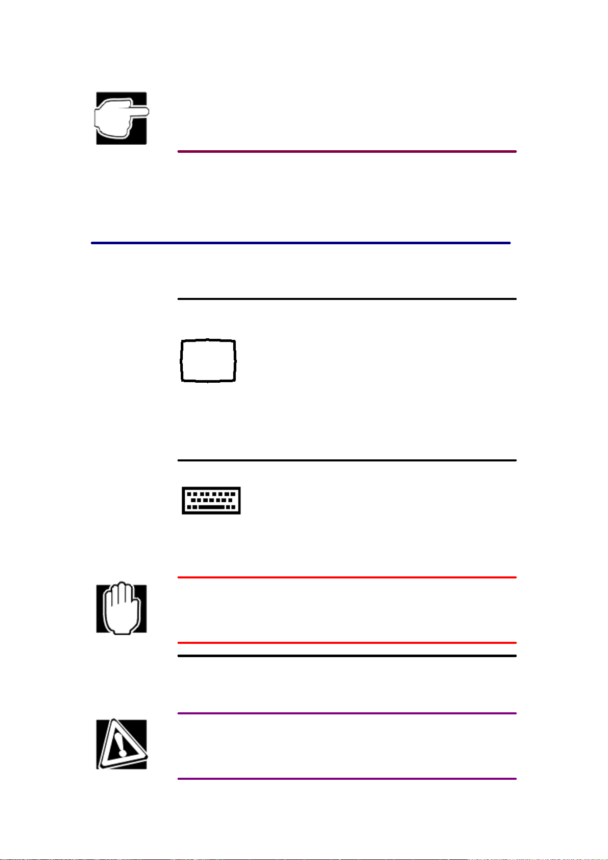
Other icons used
Additional icons highlight other helpful or educational information:
This icon provides technical information about the unit.
This icon denotes helpful hints and tips.
This icon indicates the definition of aterm used in the text.
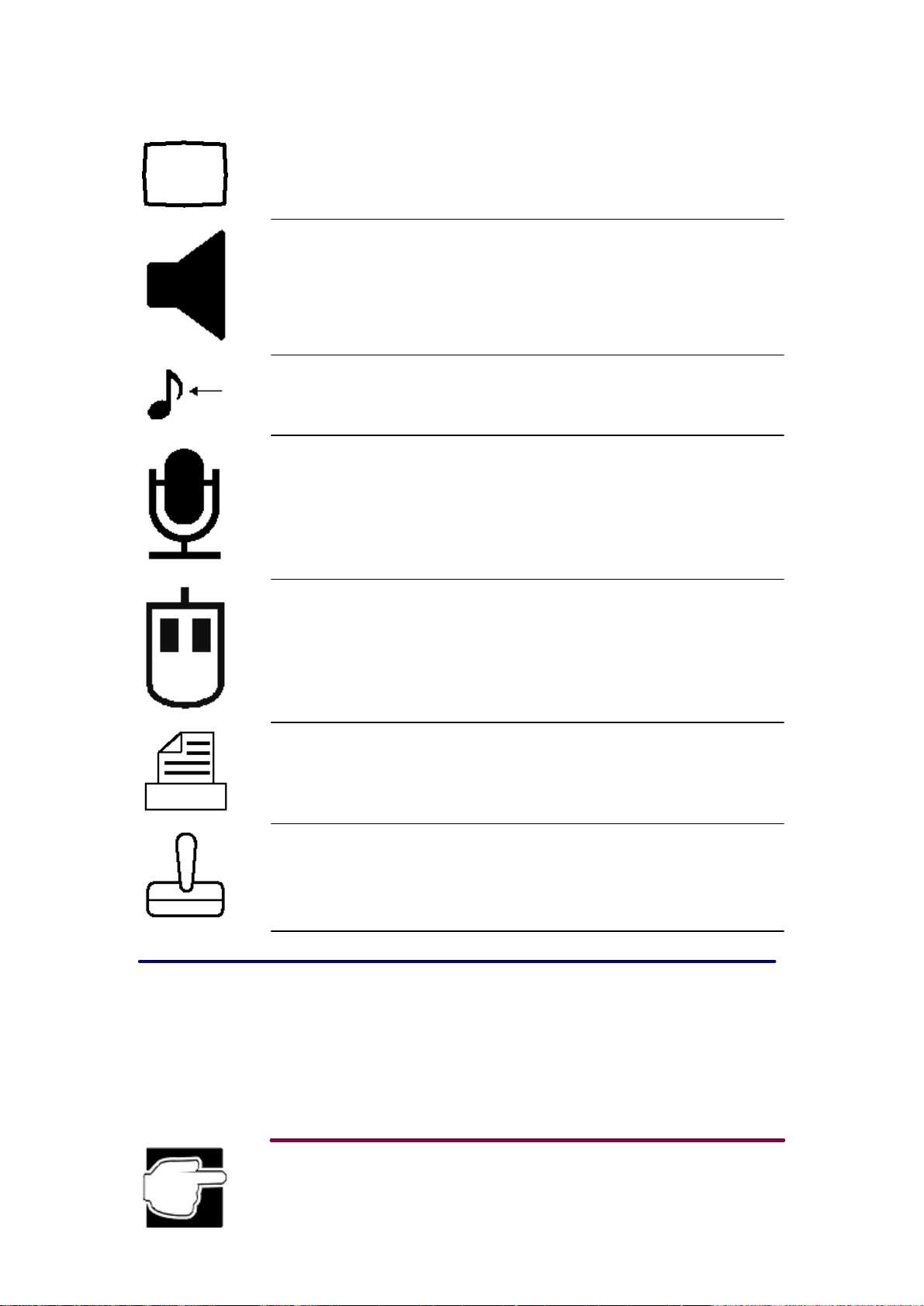
Legends
The following legends appear next toeach port and indicator onthe computer.
Computer ports
Page 5
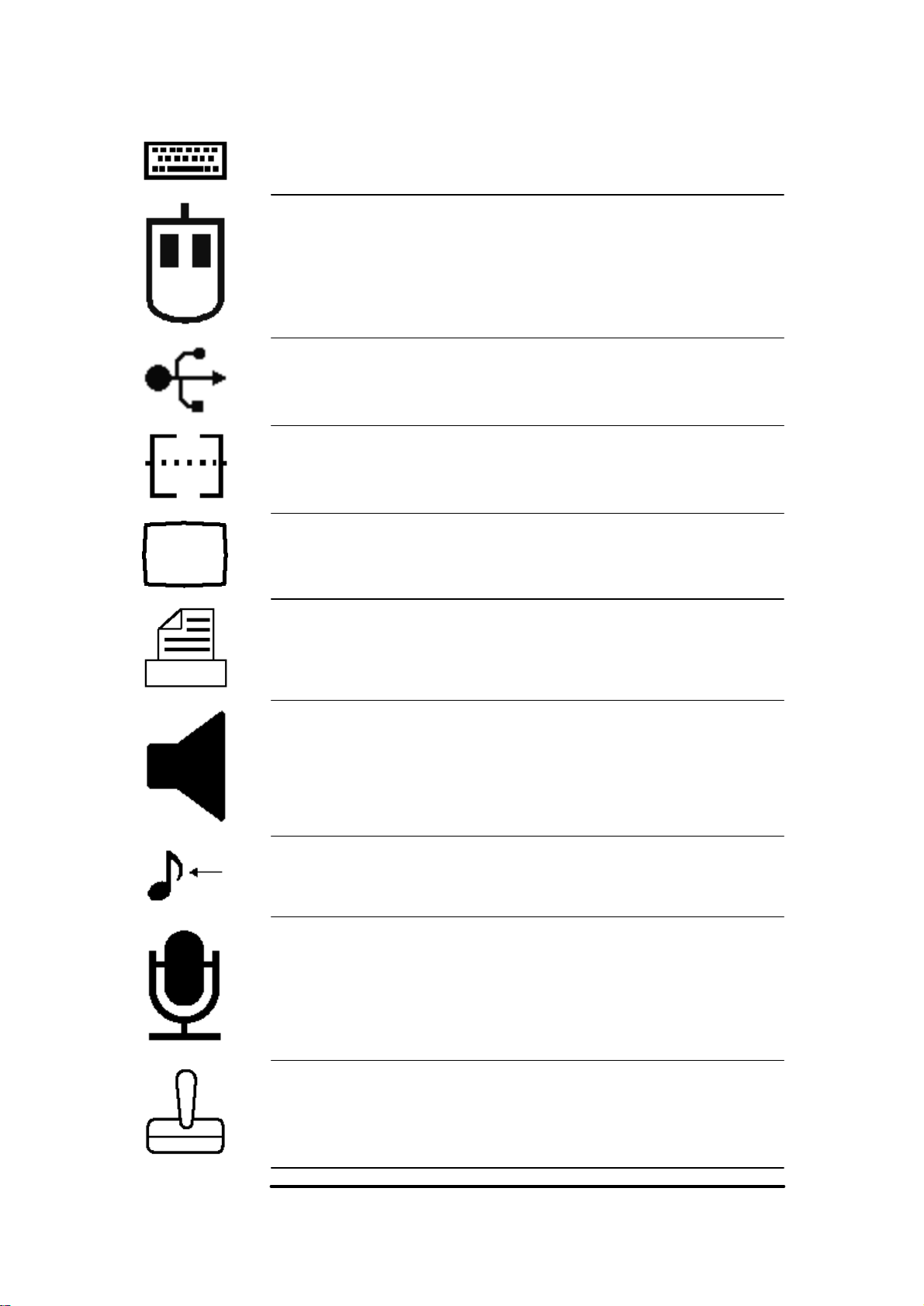
The PS/2™ keyboard port provides access toaPS/2-compatible keyboard.
The PS/2 mouse port provides access toaPS/2-compatible mouse.
The USB connector allows you toattach any of several USB devices as they become available.
The serial port lets you connect aserial printer or other serial device.
Video port for connecting amonitor.
The parallel port lets you connect aparallel printer or other parallel device, including ECP-
compatible devices.
The 3.5mm headphone jack lets you connect stereo headphones or other audio output devices,
such as external speakers.
The 3.5mm mini line-in jack lets you play and record stereo sound from an external audio device,
such as astereo system.
The microphone port accepts amonaural microphone or other audio input device for audio input.
The joystick port lets you connect ajoystick or other game device.
Indicator light and buttons
Page 6

Pressing the sleep button allows you tosuspend and resume the system.
The drive- access light indicates that the hard disk is currently in use.
The power indicator light indicates that the power is on.
• Green indicates the computer is on.
• Blinking green indicates the computer is sleeping (in Stand by mode).
• Off indicates the computer is off.
Pressing the reset button restarts the computer when it is not responding tothe keyboard. This
overrides Stand by and Resume Mode, which enable you tocontinue working from where you left
off. Use this button only if all other attempts at restarting the computer have failed.
Pressing the power button turns on/off the computer.
Other printed documentation
The computer comes with the following documentation:
q The Quick Start poster you removed when you opened the box shows how toconnect the
computer's components and get started quickly.
q This user's guide contains the technical information about how the computer works.
q Operating system documentation explaining the features and use of your Microsoft®
operating system.
q The Safety Instruction Manual provides important safeguards that must be observed in order
toavoid potential hazards that could result in personal injuries or could damage your
computer.
Service options
Toshiba offers afull line of service options built around its warranty programs. See the warranty
and service material included with the computer for registration information.
If you have aproblem or need tocontact Toshiba, refer tothe Product Support appendix. This
appendix provides phone numbers and addresses for Toshiba offices in Europe.
Page 7

Chapter 1
Getting Started
This chapter provides an overview of the 3100Series computer, including locations of external
ports and how toset up each one.
Make sure you have everything
Unpack the boxes and check the contents against your purchasing order. If any items are missing
or damaged, notify your dealer immediately.
Creating acomputer- friendly environment
The computer's micro- tower configuration allows use in any office environment. Place the
computer onan area of the desk that is large enough for the computer and any other items you
need touse, such as aprinter. Tosave space, you can place it onthe floor next toyour desk.
To prevent overheating, leave enough space around the computer and other equipment toprovide
adequate ventilation.
The work area must be free from:
q Dust, moisture and direct sunlight.
q Liquids and corrosive chemicals.
If you spill liquid into the computer, turn it off, unplug it from the AC power source, and let it dry
out completely before turning it onagain.
If the computer does not operate correctly after you turn it back on, contact your Toshiba- authorized service provider.
q Equipment that generates astrong electromagnetic field, such as large stereo speakers or
speakerphones.
q Rapid changes in temperature or humidity and sources of temperature change such as air
conditioner vents or heaters.
q Extreme heat, cold or humidity. Operate the computer within atemperature range of
10to35degree Celsius and 20% to80% non- condensing humidity.
Keeping yourself comfortable
Strain and stress injuries are becoming more common as people spend more time using their
computers. However, with alittle care and proper use of the equipment, computer work can be
comfortable throughout the day.
Using the computer keyboard incorrectly may result in discomfort and possible injury. If your
hands, wrists, and/ or arms bother you while typing, stop using the computer and rest. If the
discomfort persists, consult aphysician.
This section provides hints onavoiding strain and stress injuries. For more information, consult
books onergonomics, repetitive- strain injury, and repetitive- stress syndrome.
Placement of the computer
Proper placement of the computer and external devices is important toavoid stress- related injuries:
Page 8
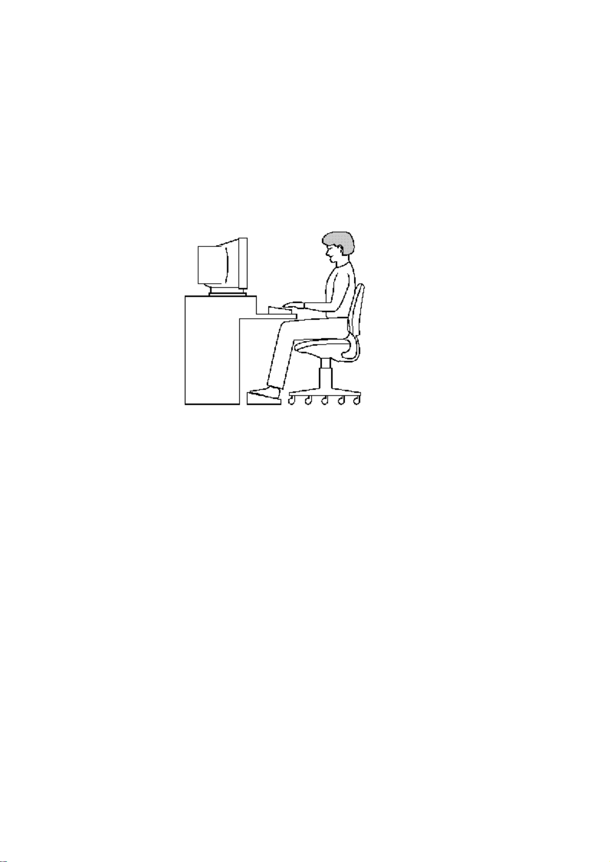
Correct posture
and positioning
of the computer
q Place the keyboard onaflat surface at acomfortable height and distance. You should be able
totype without twisting your torso or neck, and look at the screen without slouching.
q The top of the display should be no higher than eye level.
q If you use apaper holder, set it at about the same height and distance as the screen.
Seating and posture
When using the computer, maintain good posture with your body relaxed and your weight
distributed evenly. Proper seating is aprimary factor in reducing work strain. Some people find
abackless chair more comfortable than aconventional chair. Whichever type you choose, use the
following guidelines toadjust your chair for maximum computing comfort.
q Position your chair so that the keyboard is at or slightly below the level of your elbow. You
should be able totype comfortably with your shoulders relaxed and your forearms parallel
tothe floor.
If you are using aconventional chair:
q Your knees should be slightly higher than your hips. If necessary, use afootrest toraise the
level of your knees and ease the pressure onthe back of your thighs.
q Adjust the back of your chair so that it supports the lower curve of your spine. If necessary,
use acushion toprovide extra back support. Lower- back- support cushions are available at
many office supply stores.
q Sit with your back straight so that your knees, hips, and elbows form approximately
90-degree angles when you work. Donot slump forward or lean back too far.
Lighting
Proper lighting can improve the visibility of the display and reduce eyestrain.
q Position the monitor so that sunlight or bright indoor lighting does not reflect off the screen.
Use tinted windows or shades toreduce glare.
q Avoid placing the monitor in front of abright light that could shine directly in your eyes.
q If possible, use soft, indirect lighting in the computer work area.
Arms and wrists
To protect your arms and wrists:
q Avoid bending, arching, or twisting your wrists. Keep them in arelaxed, neutral position
while typing.
q Exercise your hands, wrists, and arms toimprove circulation.
Work habits
The key toavoiding discomfort or injury from strain is tovary your activities. If possible,
schedule avariety of tasks into your working day. Finding ways tobreak up the routine can
reduce stress and improve your efficiency. Some ways toimprove your work situation are:
Page 9
q Take frequent breaks tochange position, stretch your muscles, and relieve your eyes. Abreak
of two or three minutes every half hour is more effective than along break after several hours.
q Avoid performing repetitive activities for long periods. Intersperse such activities with other
tasks.
q Focusing your eyes onthe computer screen for long periods can cause eyestrain. Look away
from the computer frequently and focus your eyes onadistant object for at least thirty
seconds.
System Overview
The following illustrations show the characteristics of the 3100Series computer and the locations
of the various ports and features.
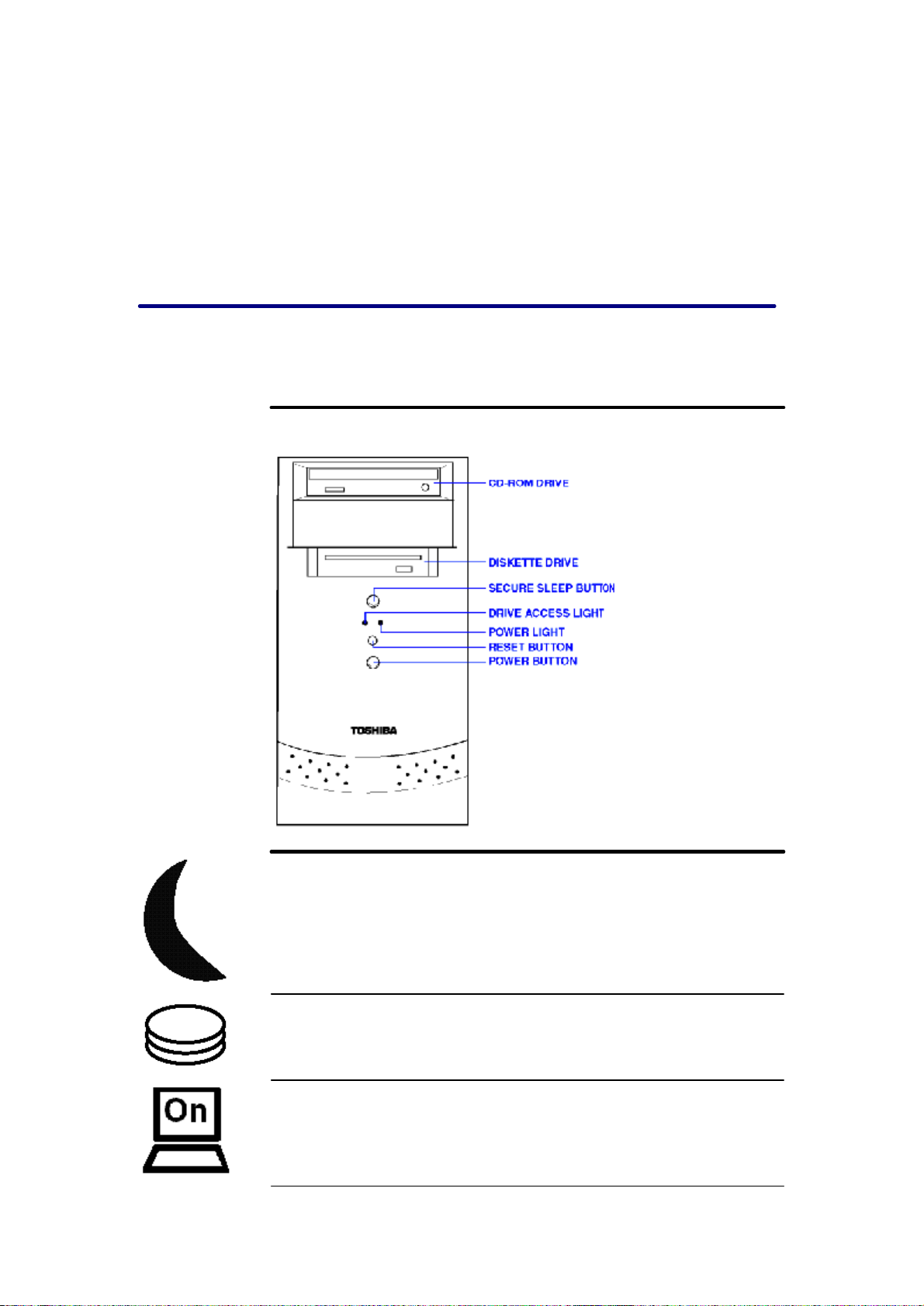
Front of the computer
Front of the
3100Series
Pressing the sleep button allows you tosuspend and resume the system. For more information, see
"Using the sleep button".
Drive- access light indicates that the hard disk is currently in use.
The power indicator light indicates that the power is on.
• Green indicates the computer is on.
• Blinking green indicates the computer is sleeping (in Stand by mode).
• Off indicates the computer is off.
Page 10
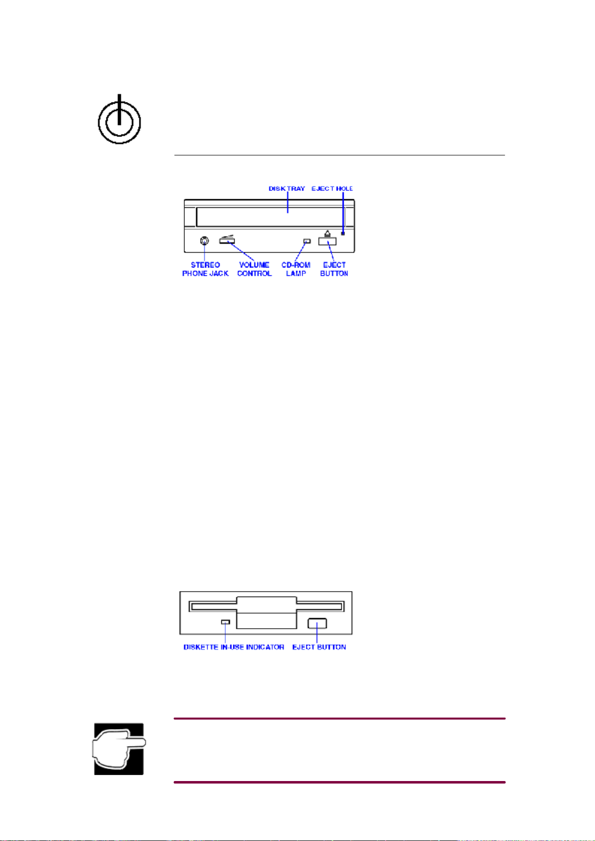
CD-ROM drive
Pressing the power button turns the computer on/off.
CD-ROM drive
q This drive can read single- sided compact discs.
q A headset or earphones can be connected tothe stereo phone jack.
q The volume control adjusts the audio output level provided the CD-ROM disc supports this.
q The CD-ROM lamp glows while the CD-ROM is being read.
q To insert or remove aCD-ROM, press the eject button toopen the drive tray. The eject
mechanism requires power tooperate. Donot press the eject button while the CD-ROM
drive lamp is lit. Doing so could affect the system.
q If the drive tray does not slide out when you press the eject button, switch off the computer
and insert aslender object, such as astraightened paper clip, into the eject hole. Donot insert
amechanical pencil lead, plastic stick, or other object that is easy tobreak into the eject hole.
Toremove the CD-ROM using the eject hole, be sure toswitch off the computer.
When handling the CD-ROM:
q Hold aCD-ROM by the edge, exercising care not totouch the surface.
q To place aCD-ROM onthe drive tray, hold it with the disk label up and by the center and
outer edge.
q When not using aCD-ROM, keep it in its case.
q Avoid exposure tohigh temperature.
q Do not bend CD-ROMs or place aheavy object onthem.
q If aCD-ROM is dusty, clean it carefully with asoft dry cloth.
Diskette drive
Diskette drive
q The drive reads both high- density and double- density 3.5-inch diskettes (1.44 MB/720 KB).
q The diskette in-use indicator glows while the diskette is being accessed.
q Pressing the eject button removes the diskette.
To prevent loss of data while the diskette drive lamp is lit:
• Do not press the eject button.
• Do not press the computer's reset button.
• Do not turn off the computer.
• Remove the diskette only when the diskette drive is not in use.
Page 11
Back of the
computer
When handling diskettes:
q Do not open the shutter.
q Do not touch the magnetic surfaces.
q Keep diskettes away from objects such as large motors or speaker phones that generate
strong magnetic fields. It may erase the data onthe diskettes.
q Do not expose diskettes todirect sunlight or toany source of heat.
q Do not place heavy objects ondiskettes.
q Store diskettes within this range of ambient conditions:
Temperature: 0to53° degrees Celsius
Humidity: 8to90% RH (Relative Humidity)
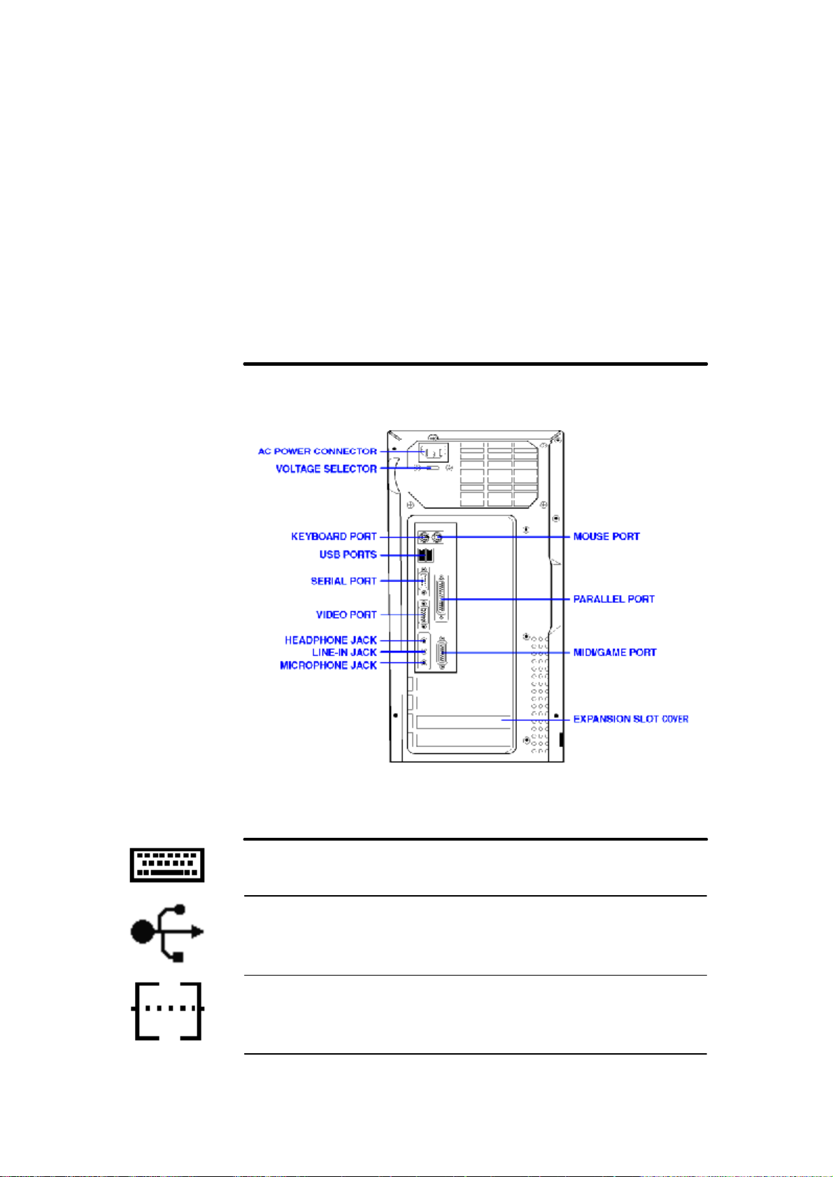
Viewing the back of your computer
The following illustrations show the back panel of the 3100Series computer.
The AC power cable plugs into the power connector.
The voltage selector switch changes the power supply toaccept either 115V or 230V AC Power.
The PS/2 keyboard port provides access toaPS/2-compatible keyboard.
The two USB connectors allow you toattach any of several USB devices as they become
available.
The serial port lets you connect aserial printer or other serial device.
Page 12
Video port for connecting amonitor.
The 3.5mm headphone jack lets you connect stereo headphones or other audio output devices,
such as external speakers.
The 3.5mm mini line-in jack lets you play and record stereo sound from an external audio device,
such as astereo system.
The microphone port accepts amonaural microphone or other audio input device for audio input.
The PS/2 mouse port provides access toaPS/2-compatible mouse.
The parallel port lets you connect aparallel printer or other parallel device, including ECP-
compatible devices.
The MIDI/ game port lets you connect aMIDI device or game joystick.
The expansion slot covers keep dust and dirt from entering the computer from unoccupied
expansion slots.
Setting up the computer
Setting up the computer involves connecting the components of your system toeach other. This
process can include:
q Positioning the system unit and peripherals.
q Connecting amonitor, keyboard, and mouse tothe system unit.
q Connecting the system unit and monitor toan AC power supply.
Page 13
AC power varies with the country; you may need toset the power switch onthe back of the system
unit. See "Setting the voltage switch".
Depending onthe computer's configuration and purpose, you may also need to:
q Connect the computer toalocal printer.
q Connect the computer toanetwork.
q Install devices in the expansion bays.
Connecting peripherals
The following sections explain how toconnect your peripherals.
Connecting amonitor
Refer toyour monitor documentation for detailed instructions onconnecting amonitor.
1.Plug the 15-pin D-sub connector onthe video signal cable into the video port onthe back of
the computer.
2.Firmly attach the cable by tightening the screws.
3.Connect the monitor's power cable tothe back of the monitor.
Connecting akeyboard
You will use the keyboard totype information and navigate around the monitor. You can use
aPS/2-compatible keyboard.
Attach the keyboard cable tothe keyboard port.
Make sure the computer is off before you attach the keyboard. Connecting aPS/2 keyboard with
the computer's power oncan damage the keyboard, the computer, or both.
Connecting amouse
You will use amouse toeasily navigate onthe screen and perform application tasks. You can use
aPS/2-compatible mouse or aserial mouse.
Make sure the computer is off before you attach the mouse. Connecting aPS/2 mouse with the
computer's power oncan damage the mouse, the computer, or both.
Connecting aPS/2 mouse
Page 14
1.Attach the PS/2 mouse cable tothe PS/2 mouse port.
2.See your mouse documentation for additional information.
Connecting aserial mouse
To connect aserial mouse, plug the mouse cable into the serial port. The mouse is ready touse.
Connecting alocal printer
Do not connect the printer cable if the computer's power is on. Doing so may damage the printer,
the computer, or both.
Before you can connect aprinter, you need toknow whether it uses aserial or aparallel interface.
Look in the printer's documentation tofind out. If the printer can be switched between serial and
parallel, choose parallel because it is faster.
You also need asuitable printer cable, which may come with your printer. Otherwise, you can
purchase one from acomputer or electronics store.
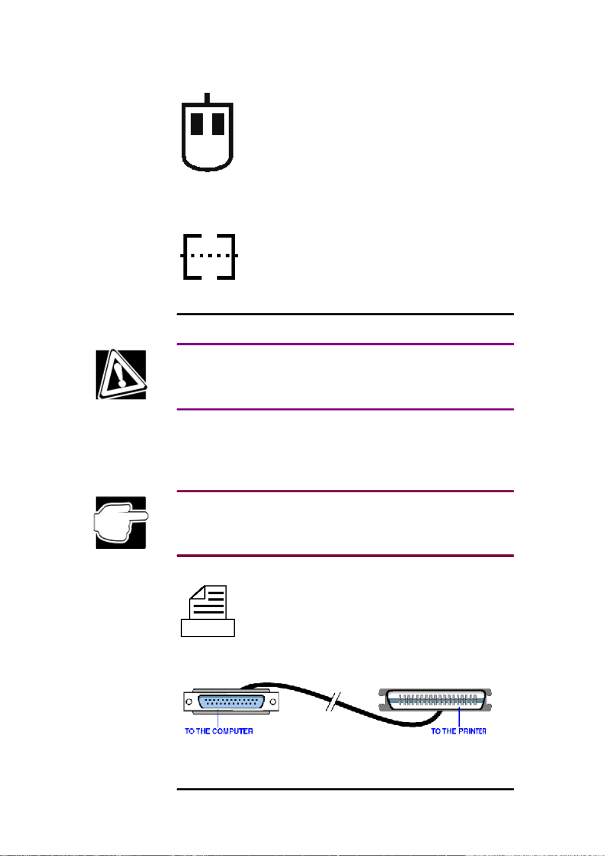
Identifying the
ends of aparallel
printer cable
If your printer is ECP- or IEEE- compliant, make sure your printer cable is an IEEE 1284 cable.
These instructions assume you have aparallel printer, which is the most common type.
1.Connect the printer cable tothe printer and tothe computer's parallel port. Use the
illustration as aconnection guide.
2.Plug the printer's power cable into alive AC outlet.
3.See your printer documentation for configuration information.
Page 15

Adding other components
Install any additional components or accessories at this time.
Adding memory
Your computer comes with enough memory torun most popular applications. With additional
memory, the computer:
q Can run more programs and open more documents at the sametime.
q Will run applications faster.
Additional memory is available from your dealer in the form of modules that fit inside the
computer.
Connecting toapower source
Before connecting your computer toapower source, read the following sections.
Power precautions
The following suggestions help prevent injury toyou or damage tothe computer.
q Do not plug in AC power cables until you have connected all the system components.
q Always plug power cables into grounded outlets.
q Never connect or disconnect components with the power on.
q Use apower filter/ surge protector (not included) for AC power connections toyour system
and any phone/ modem connections.
q In the event of asevere electrical storm, disconnect all the power cables and the telephone
cable.
q The system is configured for European standard 220V/240V 50Hz power. Before
connecting toalower voltage source (110V/120V 60Hz AC), refer tothe next section.
q Do not modify, forcibly bend, damage, place heavy objects ontop of, or apply heat tothe
power cable. The cable may otherwise become damaged, resulting in fire or electric shock.
q If the power cable becomes damaged or the plug overheats, discontinue use. There is
apossibility of fire or electric shock.
q Do not pull directly onthe power cable when removing the power plug from the power
source. Hold the power plug when removing the cable from the outlet.
q Do not remove the power plug with wet hands. This may cause an electric shock.
Setting the voltage switch
Computers purchased in Europe are configured for 230VAC operation. Computers purchased in
the United States or other countries may be set to110/120 VAC. Tooperate the computer in
acountry that uses adifferent voltage than the country of purchase, you must change the voltage
selection and use aplug adapter. The voltage selection switch is onthe back panel.
To change the voltage selection, insert the tip of apen into one of the holes onthe switch, then
slide the switch tothe correct setting.
Page 16
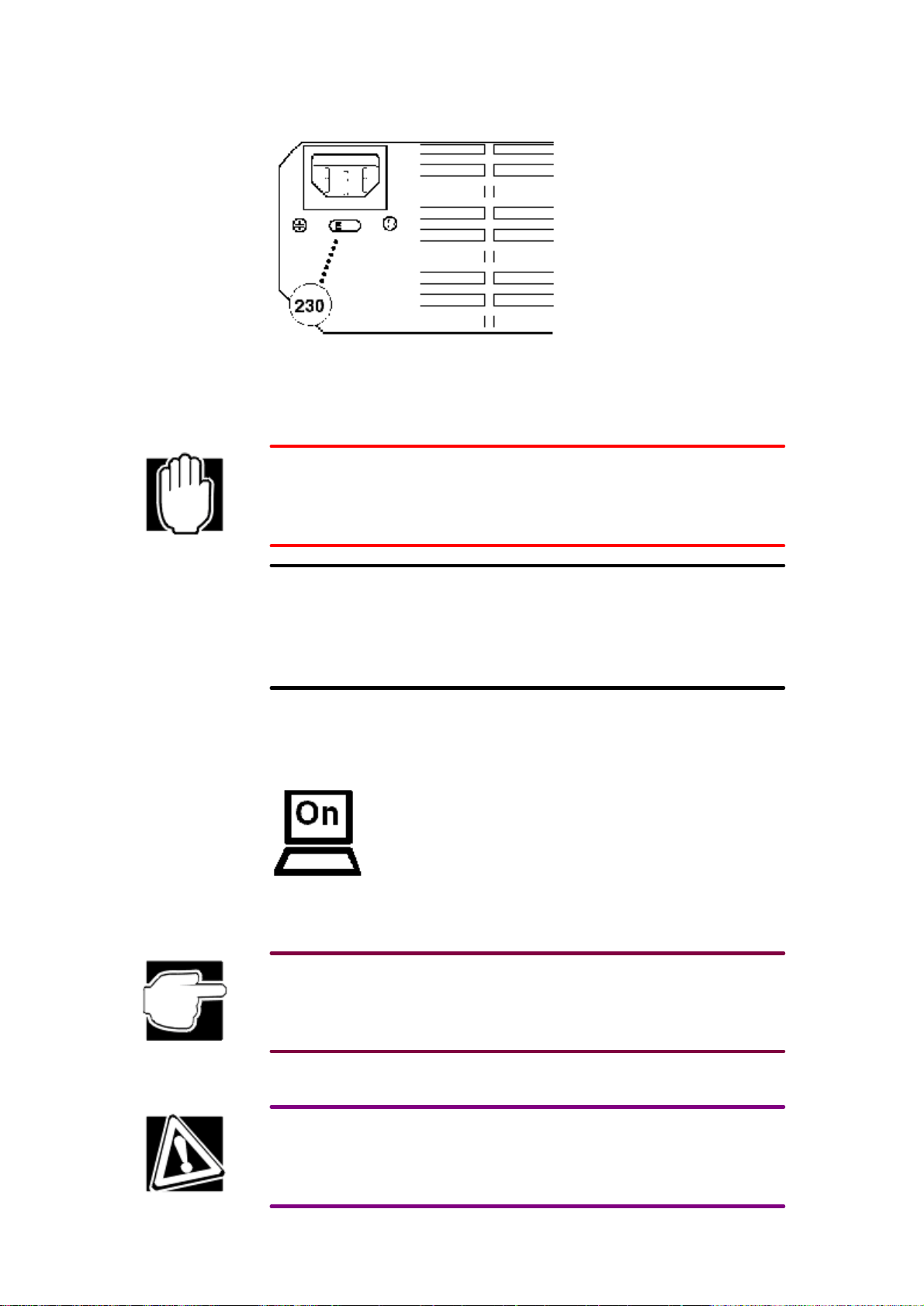
Setting the
voltage selector
q To operate the computer in the United States, make sure the voltage switch is set
to115VAC.
q To operate the computer in acountry that uses 220/240 VAC, make sure the voltage switch
is set to230VAC (the left position as you face the back of the computer).
Failure toset the voltage switch correctly will permanently damage the computer's electronics
when you turn onthe computer.
Consult your monitor's documentation tosee if its voltage setting is autoswitchable. If not, it will
require avoltage converter and aplugadapter.
Connecting ACpower
1.Plug the AC power cable into the computer's power socket.
2.Connect the power cable toalive wall outlet.
3.Connect the monitor power cable toalive wall outlet.
Turning onthe computer
1.Check that the diskette and CD-ROM drives are empty.
2.If you have aprinter connected tothe computer, turn onthe printer and wait until there is
indication that the printer is ready (on line).
3.Locate the power button and turn onthe computer.
The indicator light glows when the computer is on.
When you turn onthe computer for the first time, donot turn off the power again until the
operating system has loaded completely.
The hard disk drive light indicates that the hard disk drive is currently in use.
Do not turn off the computer if any of the drives are in use.
Page 17

Setting up your software
The first time you turn onthe computer, your Microsoft operating system setup installs the
devices it found onyour system. Setup then displays afinishing setup screen. See your Microsoft
operating system documentation for instructions oncompleting your operating system setup.
Completing the initial startup procedure
Your operating system setup may display awelcome screen. You will see options such as:
q A brief overview of your operating system.
q A list of new features in the version you are using.
q Online registration that lets you register your copy of the operating system with Microsoft.
Set up the computer tosuit your tastes and needs.
If you donot like the colors or the fonts onthe screen, you can change them by clicking ablank
area of the Desktop with the right button, then clicking Properties. This opens the Display
Properties dialog box. The Appearance tab of this dialog box allows you tochoose the
colors you see onthe screen.
Using the sleep button
After you have started the system for the first time, you can suspend and resume the system by
pressing the sleep button. Shutting down the computer with the sleep button places the computer
in apower- saving mode without completely turning it off. Torestart the computer, use the keyboard, mouse, or press the sleep button again.
Always save your work before you press the sleep button, or you could lose data.
Restoring your preinstalled software
If preinstalled software files are damaged, you will need torestore them from the Toshiba
Recovery CD-ROM or the Toshiba Tools and Utilities CD-ROM.
The Tools & Utilities CD-ROM and the Recovery CD-ROM are voluntary services of Toshiba. If
your computer has no internal CD-ROM drive, both backup CD-ROMs can be run by an optional
CD-ROM drive that is available from Toshiba.
Restoring the complete system
Page 18

Use the Toshiba Recovery CD-ROM toperform acomplete recovery of the operating system and
Toshiba Utilities, and follow the steps below.
When you reinstall the complete system, the hard disk will be reformatted and all data onit will
be lost. Make sure you have abackup copy of your data, before you perform acomplete system
recovery.
1.Make sure the computer's power is off and insert the Recovery Boot Disk in the diskette
drive, then turn onthe power.
2.Windows98/Windows95: Insert the Toshiba Recovery CD-ROM, Disk#1 in the computer's
CD-ROM drive.
3.Windows NT: Insert the Toshiba Recovery CD-ROM in the computer's CD-ROM drive.
4.Follow the on-screen directions torestore the preinstalled software.
5.Install your personal software according toinstructions that accompanied each application.
If Windows NT was preinstalled onyour computer, you can find necessary components for the
operating system in the \I386 directory of the Recovery CD-ROM.
Restoring Toshiba utilities and drivers
If Windows is working properly, individual drivers or applications can be separately restored. Use
the Tools and Utilities CD-ROM according toinstructions in the booklet contained in the CD box
toreinstall Toshiba utilities and drivers.
Page 19

Chapter 2
Learning the Basics
This chapter provides basic information on care for your computer, formatting diskettes, handling
CD-ROMs, and other general tasks related tocomputer care and usage.
Precautions
q Do not spill liquids into the computer.
If aliquid gets into any part of the computer, turn it off, unplug it from the AC power source,
and let it dry completely before turning it onagain.
q Do not turn off the computer if adrive indicator light indicates the drive is active.
Turning off the computer while it is reading from or writing toadisk may damage the disk,
the drive, or both.
q Keep the computer and disks away from objects that generate magnetic fields, such as large
stereo speakers.
Information ondisks is stored magnetically. Getting amagnet too close toadisk can erase
important files.
q Scan all new files for viruses.
This precaution is especially important for files you receive informally via diskette,
CD-ROM, email, or downloads from the Internet. Occasionally, even new programs you buy
from asupplier may contain acomputer virus. Anumber of good virus- scan programs are
available commercially.
Computing tips
Do not be afraid touse the computer, because it is only amachine. If you follow directions, you
are unlikely todothe computer any harm. So use it and have fun.
Some helpful tips are:
q Save your work frequently.
Some programs have an automatic- save feature which you can turn on. This feature saves your
file at preset intervals. See your software documentation for details.
q Back up your files todiskettes (or other removable media) onaregular basis, unless your
q Take frequent breaks toavoid repetitive- motion injuries and eyestrain.
q Before turning off the computer, always follow your operating system's procedure for
Your work stays in the computer's temporary memory until you save it todisk. If the network
you are using goes down and you must restart the computer toreconnect, or apower failure
occurs, you will lose all the work done since you last saved.
To save your work, choose Save from the File menu of the program you are using.
files reside only onanetwork drive. Label the backup copies clearly and store them in asafe
place.
It is easy toput off backing up because it takes time. However, if your hard disk suddenly
fails, you will lose all the data onit unless you have aseparate backup copy.
Page 20

shutting it down. Wait for the message that it is okay toturn off the computer.
Using the keyboard
Your computer may have aToshiba keyboard or athird- party keyboard. For specific information
about your keyboard, see your keyboard documentation.
This section gives general keyboard information.
Character keys
Typing with the character keys is very much like typing onatypewriter, except that:
q The space bar creates aspace character instead of just passing over an area of the page.
q The lowercase l (el) and the number 1are not interchangeable.
q The uppercase Oand the number 0are not interchangeable.
q The Caps Lock key changes only the alphabet keys touppercase—the number and symbol
keys are not affected.
Function, Ctrl, and Alt keys
The Function, Ctrl, and Alt keys dodifferent things depending onthe program you are using.
See your program documentation.
Numeric keypad
The ten- key keypad allows you toenter numbers quickly when you press Num Lock and the
num lock light glows. When the light is off, you can use the functions shown beneath the numbers
onthe keys.
Keyboard indicators
The caps lock light glows when you press Caps Lock. When this light is on, pressing aletter key
onthe keyboard produces an uppercase (capital) letter.
The num lock light glows when you press Num Lock.
The scroll lock light glows when you press Scroll Lock. See your software documentation for
details onthis key.
Formatting adiskette
It is common topurchase diskettes preformatted; however, you may want toformat aused diskette
for reuse.
Formatting adiskette erases all information currently onthe diskette. Donot format adiskette
unless you are sure it is blank or contains only files you no longer need.
Before formatting adiskette:
q Set the diskette towrite- enabled. The tab at the left corner of the diskette should cover the
square hole.
Page 21

Write-enabled
diskette
q Check that the diskette does not contain information you may need. Insert the diskette in the
drive, click Start, point to Programs, click Windows Explorer and click the A:
drive tosee what the diskette contains.
To format the diskette:
1.Double- click the My Computer icon.
2.Click A: with the secondary button, then click Format.
3.Make sure the options in the Format dialog box are set correctly, especially the Capacity
option.
You cannot format 720KB diskettes for 1.44MB.
4.Click Start.
Your operating system formats the diskette, displaying the Format Results screen when
it is finished.
5.Click Close.
6.Press the diskette eject button and remove the diskette from the drive.
7.To format another diskette, insert it into the drive and repeat steps 4through 6.
8.When you've finished formatting diskettes, click Close toexit the Format dialog box.
9.Close the My Computer window.
Modem and network communications
Your computer can be equipped with amodem and/ or anetwork adapter board, depending onthe
system configuration you choose. This section provides general information onmodem and
network connections.
Connecting amodem
You can install amodem in one of the computer's expansion slots. Toestablish aserial modem
connection and connect, only requires you toconnect the modem toastandard, voice- grade
telephone line using atelephone cable and modular phone jack. See your modem documentation
for instructions.
If you are using ahome telephone line equipped with call waiting, disable call waiting before
connecting through the modem. Call waiting interrupts modem transmissions.
Connecting the computer toanetwork
Your computer has aLAN jack onthe back of your computer. For specific information about
connecting tothe LAN or WAN, consult your network administrator.
Page 22

When you are connected toanetwork, doNOT use the Windows Suspend or Stand by command,
because you may lose access tothe network when you turn onthe computer again.
Accessing the Internet
The Internet is anetwork of computer networks located all around the world. Toaccess it, you
must have an Internet Service Provider (ISP).
You access the Internet using aspecial program called abrowser. Although your operating system
most likely comes with abrowser, you can install and use any commercially available browser.
Toshiba's online resources
Toshiba maintains anumber of online sites towhich you can connect. These sites can provide
information about Toshiba products, give help with technical questions, and keep you up todate
with future upgrades.
q Toshiba's 24-hour BBS is agood source for Toshiba utilities files and computing information
such as technical bulletins. See the Product Support appendix for more information.
q Toshiba's home pages onthe World Wide Web are:
http://www.toshiba.com
worldwide Toshiba corporate site
http://www.computers.toshiba.com
marketing and product information in the USA
http://www.pcsupport.toshiba.com
product support in the USA
http://www.toshiba-europe.com.
(Europe)
http://www.toshiba.co.jp
(Japan)
Turning off the computer
It is agood idea toturn off the computer when you will not use it for awhile.
q Use the Sleep button topower down major components without shutting down the
computer. Toresume work, press the Sleep button again.
q If you have work in progress and expect toresume shortly, you can use the Suspend
command (if your Microsoft operating system includes one) tosave your system settings so
that, when you turn onthe computer again, you automatically return towhere you left off.
To leave the computer turned off for alonger period, use your operating system's shut down
command.
Do not turn off the power if adisk activity light onthe indicator panel is on. Doing so may
damage your hard disk.
Caring for the computer
Page 23

This section offers tips oncleaning and moving the computer and protecting the data stored
ondisks and compact discs.
Cleaning the computer
Keep liquid, including cleaning fluid, out of the computer's keyboard and other openings. Never
spray cleaner directly onto the computer. Never use harsh or caustic chemical products toclean
the computer.
To keep the computer clean, gently wipe the monitor and exterior case with alightly dampened
cloth. Ask your Toshiba dealer for suggestions regarding appropriate cleaning products.
Moving the computer
1.Make sure all disk activity has ended (the drive indicator light stops glowing).
2.If adiskette is in the diskette drive, remove it.
3.If aCD is in the CD-ROM drive, remove it and securely close the drive tray.
4.Shut down the operating system and turn off the computer.
5.Disconnect all cables.
Caring for your diskettes
q Store your diskettes in their boxes or other containers toprotect them and keep them clean.
q Do not slide back the protective metal cover.
q Do not touch the magnetic surface of adiskette. Fingerprints can prevent the drive from
reading the data held onadiskette.
q Do not twist or bend adiskette.
q Keep diskettes at room temperature and donot expose them todirect sunlight because it
could corrupt or destroy data.
q Do not place heavy objects onyour diskettes.
q Do not eat, smoke or use erasers near your diskettes. Foreign particles can damage the
diskette's surface.
q Keep your diskettes away from sources of magnetism, such as speakers and radios, since
these can destroy data.
q If adiskette is dirty, clean it with asoft cloth moistened in water. Donot use cleaning fluids.
Caring for your compact discs
q Store your CDs in their original containers toprotect them from scratches and keep them
clean.
q Do not bend aCD or place heavy objects ontop of it.
q Do not apply alabel or otherwise mar the surface of aCD.
q Hold aCD by its outside edge. Fingerprints onthe surface of aCD can prevent the drive
from reading the data properly.
q Do not expose CDs todirect sunlight or extreme heat or cold.
To clean aCD that is dirty, wipe it from the centre outwards (not in acircle) with aclean dry
cloth. If necessary, moisten the cloth with water or aneutral cleaner (not benzine or rubbing
alcohol). Let the CD dry completely before inserting it in the drive.
Page 24

Chapter 3
Hardware for the 3100 Series
This chapter provides technical information onthe computer hardware. It shows how toopen the
case toget inside the computer tochange damaged parts or toupgrade components.
Accessories for the 3100 Series
For details about accessories currently available from Toshiba for the 3100Series computers, see
Toshiba's Web site onthe Internet:
http://www.toshiba-teg.com
Opening the case
The computer's case is designed tobe easily removed so that you can access all components and
the motherboard.
Please read the following cautions before you begin. They apply toall the electronic components
in your system.
System components can be extremely sensitive toelectrostatic discharge (ESD) and require
careful handling toavoid damage. When installing or removing components, always work
onaflat, static- free surface.
Keep components in their antistatic packaging until you are ready toinstall them.
Wear an antistatic wrist strap or touch the computer's metal chassis before you handle
components.
Before opening the case
Before you open the computer case, follow these steps:
1.Follow your operating system's shutdown procedure before you turn off the computer.
2.On the front panel, press the power button toturn off the computer.
3.Unplug all computer and peripheral power cables from the wall outlets or from your surge
protector.
4.Disconnect all cables from the computer.
Failure todisconnect power, telecommunications links, networks, or modems before you open the
system or start any procedures can result in personal injury or equipment damage. Some circuitry
onthe motherboard may continue tooperate even though the power is off.
Removing the case
For most servicing, only one side panel needs tobe removed. This should be the only part you
need toremove to:
q Add memory
Page 25

Location of the
case screws
q Install an expansion card
q Install a5.25-inch device in one of the 5.25-inch device bays
To remove the left panel:
1.Remove the two screws from the rear of the case that attach the left panel.
Pulling the panel
back
2.Pull the case toward you about an inch, then lift the case up and off the machine.
Page 26

Lifting the panel
off
For more extensive servicing, you need toremove the right panel. Toremove the other panel:
1.Remove the three screws at the rear of the case that attach the remaining panel.
2.Pull the case toward you about an inch, then lift the case up and off the machine.
Pulling the panel
back
Page 27

Lifting the panel
off
Removing the front bezel
You only need toremove the front bezel toinstall ahard disk drive.
To remove the front bezel:
1.Pry the front bezel away from the cabinet, starting from the bottom.
Locating the
bezel attach
points
The front bezel should part from the cabinet easily.
Page 28

The 3100Series
with the front
bezel removed
Locating the internal components
Removing the case and front bezel completely exposes all internal components for service.
Locating the
internal
components
As you work inside the computer, make sure you donot disconnect or damage other connectors,
cables or devices.
The power supply and cooling fan may be easily removed for replacement. For more information,
see "Power supply and cooling fan".
The 5.25-inch device bays hold aCD-ROM drive and one 5.25-inch device bay available for
expansion. For more information onreplacing a5.25-inch device, see "5.25-inch device bays".
The 3.5-inch diskette drive is located below the two 5.25-inch devices.
The motherboard contains several configurable and upgradable features. For more information,
Page 29

The 5.25-inch
device bays
see "Motherboard".
Up totwo 5.25-inch EIDE hard disk devices may be fastened tothe front of the chassis. For more
information onreplacing ahard disk drive, see "Hard disk drive chassis".
There are several expansion card slots available. For more information onreplacing an expansion
card, see "Expansion cards".
5.25-inch device bays
The 5.25-inch device bays hold up totwo IDE devices. The computer can have aCD-ROM drive
in one of the bays.
Hardware devices use certain address settings and configuration values touniquely identify them
in the computer. Toeliminate potential hardware conflicts:
• Keep achecklist of all devices and their settings.
• Make sure the device you are adding is compatible with your Microsoft operating system.
• Request the latest 32-bit drivers from your device vendor.
• If you install an EIDE hard disk drive in asystem with an SCSI drive, the EIDE drive will
automatically become the boot drive.
By convention, the connectors are labelled as "IDE" connectors, but the devices are enhanced
IDE (EIDE) devices.
Things tokeep in mind while installing ahard disk drive:
q Work onaflat, static- free surface. If you're not wearing an antistatic wrist strap, touch the
computer's metal chassis toground any static charge you have built up before handling any
electronic components.
q Keep the drive in its antistatic bag until you are ready toinstall it.
q Do not touch circuit board components onthe drive.
q Do not drop the drive.
q Do not place the drive onthe antistatic bag or slide it over any surface.
To add a5.25-inch device:
1. Shut down the computer, set the AC switch onthe back of the computer toOFF and unplug
the power cable.
2.Remove the side panel and front bezel. For more information, see "Opening the case".
3.Check the existing connections. Tolocate and identify the connectors, see "Motherboard
connectors and jumpers".
The motherboard has two IDE connectors: aprimary device connector and asecondary
device connector. The primary device connector is used for hard disk drives and the
Page 30

secondary connector is used for devices in the upper 5.25-inch device bay. Be sure tomatch
the red stripe (pin 1) onthe cable connector with pin 1onthe motherboard connector.
4.Locate the extra IDE drive connector onthe end of the IDE cable that is attached tothe back
of your existing CD-ROM drive. You will be connecting your new drive tothis connector.
5.Locate an available power supply connector. You will be connecting your drive tothis
connector.
6.Unpack your 5.25-inch device kit and check that it is complete.
When you add anew device tothe IDE connector that controls your existing device, you must
configure one device as the "master" and the other device as the "slave."
Toshiba recommends that you configure the new device as the "slave."
7.Follow the device manufacturer's instructions toconfigure the new device's jumpers so it will
act as aslave device.
A pair of tweezers may make the job of moving tiny jumper shunts much easier.
8.Unplug the IDE cable and power cable from the back of your CD-ROM drive. The drive is
currently in the upper slot of the 5.25-inch device bay.
9.Remove the front device spacekeeper faceplate.
10.Slide in the new device, and fasten it tothe chassis with two screws onthe right side. No
screws are necessary onthe left side.
11.Connect the IDE, power and any other cables tothe new device.
12.Replace the front bezel and case.
Configuring the new device
Before you can use your new device, it will have tobe configured from the operating system.
Follow the instructions provided by the manufacturer.
To configure the device:
1.While booting the computer, press F2 toenter the setup utility.
2.Select Autoconfiguration.
Setup automatically selects the optimal settings for maximum capacity and performance, and
assigns device letters.
If the operating system is unable toconfigure the device automatically, you can define the
device settings manually.
To determine which settings touse, refer tothe new device's documentation.
Write down the drive type and settings of your existing device for future reference, or in case you
inadvertently change this information.
If this device is ahard disk drive, it must also be partitioned and formatted. For more information,
see "Partitioning and formatting the new drive".
Power supply and cooling fan
The power supply and integral cooling fan supplies the computer with the necessary power torun
Page 31

The power supply
unit cabling
the equipment. It may be necessary toremove the power supply for replacement, or togain access
tothe motherboard components hidden behind it.
To remove the power supply and cooling fan:
1.Shut down the computer, set the AC switch onthe back of the computer toOFF, and unplug
the power cable.
2.Remove the both the left and right panels. For more information, see "Opening the case".
3.Disconnect the power supply's cables tothe motherboard and all peripheral devices such as
the diskette drive, CD-ROM drive and hard disk drive. It may help tolabel the connectors
tofacilitate reinstalling them.
Locating the
power supply
screws
4.Remove the four screws from the rear of the computer cabinet and slide the power supply out.
5.Push the power supply into the cabinet about an inch and lift it out.
To reinstall the power supply, reverse the above procedure.
Page 32

Locating the hard
disk drive
mounting
locations
Hard disk drive chassis
The hard disk drive chassis can hold up totwo hard disk drives.
Hardware devices use certain address settings and configuration values touniquely identify them
in the computer. Toeliminate potential hardware conflicts:
• Keep achecklist of all devices and their settings.
• Make sure the device you are adding is compatible with your Microsoft operating system.
• Request the latest 32-bit drivers from your device vendor.
• If you install an EIDE hard disk drive in asystem with an SCSI drive, the EIDE drive will
automatically become the boot drive.
By convention, the connectors are labelled as "IDE" connectors, but the devices are enhanced
IDE (EIDE) devices.
Things tokeep in mind while installing ahard disk drive:
q Work onaflat, static- free surface. If you're not wearing an antistatic wrist strap, touch the
computer's metal chassis toground any static charge you have built up before handling any
electronic components.
q Keep the drive in its antistatic bag until you are ready toinstall it.
q Do not touch circuit board components onthe drive.
q Do not drop the drive.
q Do not place the drive onthe antistatic bag or slide it over any surface.
Diskette drives and other devices that have a3.5-inch form factor require a5.25-inch mounting
frame. The manufacturer should provide this or you can purchase one from acomputer store.
To install ahard disk drive:
1.Shut down the computer, set the AC switch onthe back of the computer toOFF and unplug
Page 33

the power cable.
2.Remove the side panel and front bezel. For more information, see "Opening the case".
3.Check the existing connections. Tolocate and identify the connectors, see "Motherboard".
The motherboard has two IDE connectors: aprimary device connector and asecondary
device connector. The primary device connector is used for hard disk drives and the
secondary connector is used for devices in the upper 5.25-inch device bay.
The hard disk drive should be attached tothe primary IDE connector and the CD-ROM
tothe secondary connector. Be sure tomatch the red stripe (pin 1) onthe cable connector
with pin 1onthe motherboard connector.
4.Locate the extra IDE drive connector onthe end of the IDE cable that is attached tothe back
of your existing hard disk drive. You will be connecting your new drive tothis connector.
5.Locate an available power supply connector. You will be connecting your drive tothis
connector.
6.Unpack your hard disk drive kit and check that it is complete.
When you add anew hard disk drive tothe IDE connector that controls your existing drive, you
must configure one drive as the "master" and the other drive as the "slave."
Toshiba recommends that you configure the new drive as the "slave."
7.Follow the hard disk drive manufacturer's instructions toconfigure the new drive's jumpers
so it will act as aslave drive.
A pair of tweezers may make the job of moving tiny jumper shunts much easier.
8.Unplug the IDE cable and power cable from the top of your existing hard disk drive. The
drive is currently in the upper drive location in the chassis.
9.Install the new hard disk drive into the chassis using four screws.
10.Connect the IDE and power cables tothe new hard disk drive.
11.Replace the front bezel and side panel.
Configuring the new drive
Before you can use your new hard disk drive, it will have tobe configured, partitioned and
formatted from the operating system. Follow the instructions provided by the manufacturer.
To configure the disk drive:
1.While booting the computer, press F2 toenter the setup utility.
2.Select Autoconfiguration.
Setup automatically selects the optimal drive settings for maximum capacity and
performance, and assigns drive letters. The original drive is C:, and the second drive is drive
D:.
If the operating system is unable toconfigure the drive automatically, you can define the
drive settings manually.
To determine which settings touse, refer tothe new drive's documentation.
Write down the drive type and settings (cylinders/ heads/ sectors) of your existing drive for future
reference, or in case you inadvertently change this information.
Page 34

Partitioning and formatting the new drive
Before you can use the new drive, it must be partitioned and formatted. Follow the instructions
provided by the manufacturer.
Take care not toaccidentally format your existing drive. Formatting destroys all data onadrive.
Expansion cards
The 3100Series computer has three PCI card slots for additional components.
IRQ setup
Set an appropriate IRQ level for the expansion card. See "Interrupt levels".
For the setup procedures, see "System Setup Utility (SSU)" and the manuals for the individual
expansion cards. Toshiba recommends that you record the settings in the Device Log in case you
need tochange them when you install other devices. For more information, see "Device Log".
Hardware devices use certain address settings and configuration values touniquely identify them
in the computer. Toeliminate potential hardware conflicts:
• Keep achecklist of all devices and their settings.
• Make sure the device you are adding is compatible with your Microsoft operating system.
• Request the latest 32-bit drivers from your device vendor.
Installing acard
Use caution when installing or removing expansion cards. Protect your hands from possible injuries caused by sharp projections onthe boards and the computer.
Do not touch any parts except those necessary for installing the device. There are many high-
voltage parts that are dangerous totouch.
To install an expansion card:
1.Shut down the computer, set the AC switch onthe back of the computer toOFF, and unplug
the power cable.
2.Remove the side panel. For more information, see "Opening the case".
3.Locate and remove the I/O slot cover onthe rear of the cabinet.
4.Install the expansion card into the desired expansion slot. Be careful not tocatch the card
onthe slot's top and bottom tabs.
5.Secure the expansion card in place by using the screw from the I/Oslot cover.
6.Connect any cabling necessary for the operation of the expansion card.
7.Replace the case.
8.Plug in the power cable and turn onthe computer.
9.Follow the manufacturer's instructions for setting up the expansion card.
Jumper settings onthe card or in the computer BIOS may have tobe changed. Some expansion
cards may also need tobe set up using avendor- supplied setup diskette.
Page 35

Locating the
motherboard
components
Motherboard
The motherboard holds the microprocessor, memory, ports, expansionslots, CMOS battery and
IDE controller.
The following components are identified in the illustration.
q CPU. Intel celeron microprocessor; speed determined by your build-to-order specifications.
q Memory slots. Two 168-pin DIMM sockets allow system memory from 16MB to512MB of
SDRAM.
q Expansion card connectors. Connections from the motherboard tothe expansion card.
q CMOS battery. The battery maintains CMOS setting when the computer is turned off.
q The Audio Modem Riser (AMR) Connector. AMR defines acommon standard interface for
adding amodem or audio riser card.
q Digital Flat Panel Port supports flat panels with adigital signal for superior quality. Many
flat panels only use the analog signal that was initially designed for CRT monitors.
Motherboard connectors and jumpers
There are several jumpers onthe motherboard toconfigure various options and settings. All other
configurable settings are performed in the BIOS, or the computer automatically adjusts its own
settings for different components.
Page 36

Locating the
motherboard
connectors and
jumpers
The motherboard power connector supplies the necessary current from the power supply.
The Secondary IDE, Primary IDE and Diskette connectors are the data cable connections for the
respective devices.
A front USB can be enabled. Please use the USB jumpers pointed out in the previous graphic.
The USB jumpers look like this:
USB
JP4
JP5
CMOS setting jumpers can be used tolock, unlock or reset password and others. The CMOS
jumpers look like this:
JP7
JP8
JP9
JP10
JP11
Replacing the 3100Series CPU
The CPU is onthe motherboard.
Work onaflat, static- free surface. Wear an antistatic wrist strap or touch the computer's metal
chassis. Donot place the CPU onthe antistatic bag or slide it over any surface.
FRONT
1–2
1–2
BACK
2–3
2–3
OFF = LOCK
ON = UNLOCK
NO REBOOT
CLEAR PWD/CMOS
SAFE MODE
CHASSIS INTRUSION
For the Celeron processor:
Page 37

Celeron CPU
Removing the
CPU
1.Prior toremoving/ replacing the CPU, refer to"Opening the case".
2.Unplug the CPU's fan cable.
3.Release the metal latch that secures the CPU tothe motherboard.
4.Pull the lever slightly outwards and then up toremove the CPU from the board.
5.Install the new CPU, ensuring that you seat it firmly onthe board, push the lever down
toconnect the CPU and secure it with the metal latch. Replace the fan cable.
6.Refer tothe CPU documentation for any required special settings.
7.Replace the panel and turn onthe power.
8.Verify onthe monitor that the computer has recognised the new processor.
Replacing the CMOS battery
A lithium battery, installed onthe motherboard, provides power for the real- time clock (RTC) and
CMOS RAM. The battery will last for several years.
When the battery starts toweaken and the voltage drops below acertain level, you may notice that
the date and time are wrong. This is an indication that the battery needs replacing.
If you replace the battery incorrectly, it can cause injury or damage the system. Always use the
same or an equivalent type of battery.
Do not expose batteries toexcessive heat or fire.Please return battery tothe point of purchase for
proper disposal.
The following procedure assumes you have opened the case and are observing ESD precautions.
Page 38

Location of the
RAM DIMM
sockets
(Refer to"Opening the case".) Toreplace the battery, follow these steps:
1.Locate the battery onthe motherboard.
Refer tothe motherboard illustration tolocate the battery. Gently pull the battery free from
its socket, taking care tonote the "+" and "–" orientation of the battery.
2.Pinch the two notches together until the battery partially pops out.
3.Install the new battery in the socket.
4.Reassemble the computer and turn it back on.
5.Run the Setup program and reset the system time and date.
Dispose of used batteries in asafe, environmentally responsible manner. The literature that
comes with the computer may include an insert about disposing of batteries. If not, check with
your local government for information onwhere torecycle or dispose of old batteries. If you
cannot find the information you need, contact Toshiba for assistance. See the Product Support
appendix for ways tocontact Toshiba.
Expansion memory
The DRAM controller supports a72-bit memory data interface. It can also support 64-bit or
72-bit wide DIMM modules with or without ECC/ EC.
Synchronous DRAM (SDRAM) is supported. Memory can be configured in 1Mx64/72,
2MBx64/72, 4MBx64/72, 8MBx64/72 and 16MBx64/72 single- density DIMM modules
and up to32MBx64/72 double- density DIMM modules.
The 3100Series supports SDRAM at 100MHz.
The main memory interface provides two 168-pin DIMM sockets, DIMM0and DIMM1. This
allows system memory from 8MB to512MB of SDRAM.
The DIMM sockets support single- or double- sided unbuffered DIMM modules. The installed
DRAM type can be 8MB, 16MB, 32MB, 64MB, 128MB or 256MB DIMMs.
The DRAM controller uses the JEDEC standard serial presence detect mechanism todetect
memory and array configuration. No jumper settings are required for the memory size or type;
memory is automatically detected by the system BIOS.
3100 Series series computers are shipped with SDRAM.
3100Series memory configurations
The following shows some typical memory configurations:
DIMM sizeNonparity configurationParity and ECC
configuration
32 MB8 x 328 x 36
Page 39

64 MB16 x 3216 x 36
Memory DesiredDIMM sizeNumber of DIMMs
32 MB32 MB1
64 MB32 MB2
64 MB64 MB1
128 MB128 MB1
128 MB64 MB2
256 MB128 MB2
512 MB256 MB2
Rules for installing DIMMs
Keep the following items in mind when adding or replacing DIMMs.
q DIMM sockets donot need tobe installed in pairs.
q DIMM sockets can be filled in any order.
q The DRAM timing register is programmed touse the timings of the slowest DRAMs
installed.
Installing DIMMs
The following procedure assumes you have opened the case and are observing ESD precautions.
(Refer to"Opening the case") Toinstall DIMMs:
1.Holding the DIMM only by the edges, remove it from its antistatic package.
2.Make sure the clips at either end of the socket are pushed away from the socket.
3.Position the DIMM above the socket at about a90-degree angle relative tothe motherboard.
Make sure the two small notches in the bottom edge of the DIMM align with the keys in the
DIMM socket.
4.Insert the bottom edge of the DIMM into the DIMM socket and make sure it is seated
correctly.
5.Gently push the top edge of the DIMM until the retaining clips at each end of the socket snap
into place.
Inserting DIMM
module
Removing DIMMs
1.Gently spread the retaining clip at each end of the socket.
Page 40

Removing
aDIMM module
2.Holding the DIMM only by the edges, lift it away from the socket, and store it in an antistatic
package.
Page 41

Chapter 4
Troubleshooting
This chapter provides you with hints and tips if your computer does not perform as it should. It
also provides the resources you need if the problem is more serious.
Some problems you may encounter when using the computer are relatively easy toidentify and
solve. Others may require help from your dealer or the manufacturer of asoftware program.
This chapter aims tohelp you solve many problems yourself without additional help. It covers the
problems you are most likely toencounter.
Read the section headings, then gotothat section covering the problem. Each section describes
aproblem and provides asolution. Read the section and see if it describes your problem. If so,
follow the steps for solvingit.
If all else fails, contact Toshiba. See "If you need further assistance" in thischapter.
Problem- solving tips
To make your computer experience more productive and problem- free, read the following
sections.
Read the manuals
It is very difficult toprovide afail- safe set of steps you can follow every time you experience
aproblem with the computer. Your ability tosolve problems will improve as you learn about how
the computer and its software work together.
Get familiar with all the manuals provided with the computer, as well as the manuals that come
with the programs and devices you purchase.
Your computer store or book store sells avariety of self- help books you can use tosupplement the
information in the manuals.
Defend yourself against viruses
Viruses, while apotential problem, need not have adevastating effect onthe computer. By taking
afew, simple precautions, you can avoid infection. By making sure you have acomplete backup
of all your programs and data files, you can ensure aspeedy recovery if you dorun into problems.
There are many virus- detection/ removal programs available. Ask your dealer for help in selecting
one that meets your needs.
Take abreak
If aproblem is taking along time tosolve, stop. Stand up and take adeep breath. Often, you can
find asolutions toaproblem just by stepping away from it for afew moments.
Problems that are easy tofix
The more you work with the computer, the more likely you are toencounter one or more of the
following problems. You can resolve them relatively easily.
Your program stops responding.
If you are working with aprogram that suddenly freezes all operations, chances are the program
has stopped responding. This problem can occur from time totime. Toexit the failed program
without shutting down Windows or closing other programs:
Page 42

1.Press Ctrl, Alt and Del simultaneously (once).
If you are using Windows NT, apreliminary dialog box appears. Click Task List toget tothe
Close Program dialog box.
2.In the Close Program dialog box, look for the words not responding beside aprogram's
name, select the program, then click End Task.
Closing the failed program should allow you tocontinue working. If it does not, continue
with step 3.
3.Close the remaining programs by clicking End Task.
4.Click Shut Down, select Restart, then click Yes.
Your computer shuts down and restarts Windows.
Avoid pressing Ctrl, Alt and Del simultaneously twice torestart the computer unless absolutely
necessary. Close all open programs before shutting down Windows tosave any data.
Your program has performed an illegal operation.
If you receive this message, record the details and consult the software manufacturer.
To record the details:
1.Click the Details button and select the text Windows displays.
2.Press Ctrl and C simultaneously tocopy the text tothe clipboard.
3.Open Notepad (click Start, point to Programs, then point to Accessories and click
Notepad).
4.Press Ctrl and V simultaneously topaste the details into Notepad.
5.Add aparagraph break and type some notes describing what you were doing when you
received the message.
6.Save the file and refer toit when you contact the software manufacturer.
You receive aNon- System Disk error message.
A diskette is in the drive while the computer is starting Windows. Remove the diskette and press
any key tocontinue.
Problems when you turn onthe computer
The computer does not start.
Make sure you attached the power cable properly and that the outlet you use is live.
Press and hold down the power button for afew seconds.
The computer starts but, when you press akey onthe keyboard or touch the mouse, nothing
happens.
You may have asoftware or resource conflict. Toclear the condition, press Ctrl, Alt and Del
simultaneously, or press the reset button.
Read the documentation that came with the conflicting device and "Resolving ahardware
conflict" in this manual.
Page 43

The computer is not accessing the disk drive(s).
Insert asystem diskette into the drive and turn onthe power.
The computer displays the Non- System disk or disk error message.
Make sure there is no diskette in the drive. If there is one, remove it and press any key
tocontinue. If pressing any key does not work, simultaneously press Ctrl, Alt and Del, or press
the reset button torestart the computer.
If the problem persists, try torestart the computer with another reliable system diskette in the
diskette drive.
Windows does not work
Once you are familiar with Windows, you can easily detect if it is not working correctly. For
example:
q Windows fails tostart after displaying its starting message.
q Windows takes along time tostart.
q Windows departs from its normal routine.
q Your display does not look right.
Unless ahardware device has failed, problems usually occur when you start the computer, change
the system configuration, add adevice, or install anew program.
If you experience any of these problems, use the options in the Windows Startup Menu.
Using startup options tofix problems
If Windows fails tostart properly, you may have tochange your system's configuration or verify
the startup procedure tofix the problem.
To open the Startup menu:
1.Restart the computer.
2.Press F8 when the computer starts.
The Startup menu displays the following options:
q Normal
q Logged (\BOOTLOG.TXT)
q Safe mode
q Step-by-step confirmation
q Command prompt only
q Safe mode command prompt only
If the computer is connected toanetwork, the Startup menu may display different versions of
Safe mode.
Normal
Use this option when there are no apparent problems with the system.
Logged (BOOTLOG.TXT)
This option creates ahidden log file named C:\BOOTLOG.TXT which records every step of the
system's startup process.
You or aqualified Windows expert can use this log file tocheck the loading and initialising of
Page 44

Windows device drivers.
A device driver is afile that contains information tohelp the computer's BIOS (Basic Input/
Output System) control the operations of devices connected tothe system.
Safe mode
This option bypasses basic startup files and starts Windows with just the mouse, keyboard, and
standard VGA display drivers enabled.
Windows NT does not support this mode at this time.
Running Safe mode allows you toundo any changes you made tothe system configuration that
may have caused your problem, such as choosing aresolution that is not supported by the display.
Safe mode bypasses the setting and allows you tochange the resolution toone supported by the
display. Once you have done this, Windows will start correctly.
Use Safe mode when:
q Windows fails tostart even in Safe mode.
q You want torun MS-DOS® commands, such as Edit, tomake changes toyour startup files.
q You want toavoid loading HIMEM.SYS (extended memory manager), or IFSHLP.SYS (file
system manager).
Windows automatically starts in Safe mode if it detects asystem startup failure or acorrupted
Registry (the file that defines how Windows is set up).
Step-by-step confirmation
With this option, the system asks you toconfirm each line of the startup process. Use this option
when:
q The startup process fails while loading the startup files.
q You need toverify that all drivers are being loaded.
q You need totemporarily disable one or more specific driver(s).
q You need tocheck for errors in the startup files.
When you select Step-by-step confirmation, you can view the startup files and device drivers
one line at atime tohelp diagnose the source of aproblem.
Command prompt only
This option starts the basic operating system with all the startup files and device drivers. Use it
when you want torun MS-DOS commands.
This option is for advanced users who are familiar with MS-DOS and know what these commands
do.
Windows can help you
Page 45

If Windows has started properly, but you still have aproblem using the computer, Windows Help
can assist you in troubleshooting the problem.
1.Click the Start button and click Help.
2.Click the Contents tab and double- click Troubleshooting.
3.Double- click the problem with which you would like help, and follow the steps onthe screen.
Resolving ahardware conflict
If you receive an error message telling you there is adevice driver conflict or ageneral hardware
problem, try touse Window's Help totroubleshoot the problem first.
1.From the Windows Help menu, click the Contents tab and select Troubleshooting.
2.Click If you have ahardware conflict and follow the steps.
If there is still aproblem, Windows should display amessage that explains the conflict.
Aplan of action
The recommended procedure for getting multiple devices towork together is toadd and set up
one device at atime. After you add each device, test it tomake sure it and all previously
connected devices work.
The device most recently connected tothe system is the one most likely tobe causing ahardware
conflict.
Resolving hardware conflicts onyour own
Computer components need resources toaccomplish atask. Adevice, such as aCD-ROM drive
or amodem, needs achannel tothe computer's central processing unit (CPU). It also needs
adirect channel tothe computer's memory tostore information as it works. These channels of
communication are commonly referred toas system resources.
Interrupt request channel
An interrupt request (IRQ) is the channel tothe CPU because it interrupts what the processor is
doing and requests some of the processor's time. If two or more devices use the same IRQ, the
processor does not know which device is asking for attention.
Direct Memory Access
Similarly, the data required by the device are stored in aspecific place or address in memory
called the Direct Memory Access (DMA). The DMA provides adedicated channel for adapter
cards tobypass the microprocessor and access memory directly. If two or more devices use the
same DMA, the data required by one device overwrite the data required by the other. If this
occurs, you have ahardware conflict.
Plug and Play
Windows NT does not support this mode at this time.
When supported, Plug and Play prevents hardware conflicts. Plug and Play is acomputer standard
that helps the system BIOS and the operating system toautomatically assign system resources
toPlug and Play- compliant devices. In theory, if every device connected tothe computer is Plug
and Play- compliant, no two devices will compete for the same system resources. You simply plug
in the device and turn onthe computer. Windows automatically sets up your system
toaccommodate the new device.
However, if you install an older (legacy) device that Windows cannot recognise, Windows may
have difficulty assigning system resources toit. As aresult, ahardware conflict can occur. Tosee
Page 46

what resources Windows has assigned tothe device, see "Checking device properties".
Resolving conflicts
There are three things you can dotoresolve hardware conflicts:
q Disable the device.
For an older device, remove it from the computer. For aPlug and Play device, see "Fixing
aproblem with Device Manager".
q Disable another system component and use its resources for the new device.
See "Fixing aproblem with Device Manager".
q Reconfigure the device so that its requirements donot conflict.
Refer tothe device's documentation for instructions about changing settings onthe device.
Fixing aproblem with Device Manager
Device Manager provides away tocheck and change the configuration of adevice.
Changing the default settings using Device Manager can cause other conflicts that make one or
more devices unusable. Device Manager is aconfiguration tool for advanced users who
understand configuration parameters and the ramifications of changing them.
Disabling adevice in Windows
1.Click the My Computer icon with the secondary button, then click Properties.
2.Click the Device Manager tab.
3.Double- click the device type todisplay the device installed.
4.Select the device and click Properties.
A dialog box displays the device's properties.
5.In the Device usage section of the dialog box, clear the check box next tothe current
configuration.
6.Click OK.
Checking device properties
Device Manager (not afeature of Windows NT) provides away toview the properties of adevice.
Properties include the name of the manufacturer, the type of device, the drivers installed, and the
system resources assigned tothe device.
1.Click the My Computer icon with the secondary button, then click Properties.
2.Click the Device Manager tab.
3.To view the device(s) installed, double- click the device type.
4.To view the properties, double- click the device.
Windows95displays the Device Properties dialog box, which provides various tabs:
q The General tab provides basic information about the device.
q The Resources tab lists the resources assigned tothe device. If you have adevice
conflict, it is shown in the Conflicting device list.
q The Drivers tab displays the drivers being used by the device.
For further information about Device Manager, refer toWindows95online help.
Fixing device- related problems
Page 47

If you donot have ahardware conflict, but think your problem relates toone of the computer's
devices, the first thing todois run asystem verification test. Asystem verification test confirms
that the factory- installed devices connected tothe computer are working. This includes testing the
memory, disk drives, display, and additional devices you may have connected tothe system.
Using Power OnSelf Test (POST)
If the Power OnSelf Test (POST) verifies that all components connected tothe system are
functional, the computer beeps once, then starts Windows.
If the POST fails
If the POST fails, the computer does one of the following:
q Stops updating the memory counter and does not proceed todisplay information or messages.
q Beeps once but displays no new messages.
q Displays random characters and does not function normally.
q Displays an error message.
Turn off the computer and make sure all optional devices are connected properly and turned
on. Then, turn onthe computer and run the test again. If the test fails asecond time, you have
demonstrated that you can reproduce the problem. Contact atrained technician.
Other circumstances
The computer normally beeps at the conclusion of asuccessful system verification. If the system
speaker is set to Disabled, this beep will not occur.
If the speaker is turned on(enabled) and the system verification completes but you donot hear
abeep, the speaker may be faulty. Though this does not affect the computer's operation, you may
wish tocontact your dealer and have it repaired.
If the system verification is successful but the operating system does not load, refer to"Problems
when you turn onthe computer". If all seems correct, treat this problem as ahardware error and
contact your dealer.
If you need further assistance
If you have followed the recommendations in this chapter and are still having problems, you may
need additional technical assistance. Contact your network administrator.
Since some problems may be related tothe operating system or the program you are using, it is
important toinvestigate other sources of assistance first. Try the following before contacting your
network administrator:
q Review the troubleshooting information in your Windows documentation.
q If the problem occurs while you are running aprogram, consult the program's documentation
for troubleshooting suggestions. Contact the software company's technical support group for
assistance.
q Consult the dealer from whom you purchased your computer and/ or program. Your dealer is
your best source for current information.
Contacting Toshiba
If you still need help and suspect that the problem is hardware- related, Toshiba offers avariety of
resources tohelp you.
The Toshiba Bulletin Board Service (BBS) can be reached free of charge from any PC with
amodem.
Toshiba's Bulletin Board Service
Toshiba's Bulletin Board Service (BBS) is available 24hours aday, and is free of charge
toanyone with aPC and amodem. From Toshiba's BBS, you can download files and obtain other
useful information tokeep your computer running at peak performance.
Be sure you set your modem toToshiba's BBS protocol:
Page 48

Data Bits: 8
Parity: None
Stop Bits: 1
See Appendix Product Support for BBS phone numbers.
Accessing Toshiba online
You can reach Toshiba onthe Internet using any Internet browser toaccess the Internet using the
addresses in Chapter 2.
Toshiba voice contact
To aid Toshiba, make sure you have:
q The computer and any optional devices related tothe problem.
q Backup copies of the operating system and all other preloaded software ondiskettes or CD.
q Name and version of the program involved in the problem along with its installation
diskettes or CD.
q Information about what you were doing when the problem occurred.
q Exact error messages and when they occurred.
See Appendix Product Support for phone numbers.
Page 49

Appendix A
Features and Specifications
This appendix lists the features of the 3100Series computer and summarizes its specifications.
Built-in features
This section lists the computer's standard features and specifications.
Technology and processor
Microprocessor
Level 1 cache
Level 2 cache
Bus Clock speed
Memory
Video Graphics Controller
Video Memory
Sound support
Storage capacity
Primary hard disk
Intel® Celeron® 400–500 MHz processor withMMX
technology
Note: Other processor speeds may be introduced as they
become available
16 KB (instruction) and 16KB (data) write- back cache
128 KB pipelined burst SRAM
66 MHz
64 MB SDRAM expandable to512MB
Intel 82810 Integrated Graphic controller with 3D Hyper
pipelined Architecture(PDP & PDI) and 2D Graphics 3
Operand raster BitBLTs accelerator
Uses main memory
Aureal 8810PCI 3D Audio System supporting 16-bit stereo,
Windows Sound System and Sound Blaster Pro®-compatible
3.5-inch Enhanced IDE drive and controller provides
nonvolatile storage for 6.44 billion bytes
Secondary hard disk
3.5-inch disk drive
The above lists are subject tochange without notice.
Ports
Space available for asecond 3.5-inch Enhanced IDE drive
Accommodates both 1.44MB high- density (2HD) and 720KB
double- density (2DD) diskettes
Page 50

Keyboard port
PS/2-compatible port allows you toconnect afull- size keyboard
Mouse port
Serial port
USB port
Parallel port
Joystick / MIDI port
Headphone jack
Line-in jack
Microphone jack
Expansion card slots
PS/2-compatible port allows you toconnect aPS/2 mouse
9-pin, RS-232C-compatible high- speed buffered 16550 UART
compatible serial port lets you connect an external modem,
mouse, serial printer or other serial device
Two Universal Serial Bus (USB) ports provide USB
connections
An IEEE 12848-bit Enhanced Capability Port (ECP) for
connecting aparallel device such as aprinter that provides
increased performance when used with an ECP- compatible
device
15-pin connector lets you connect ajoystick or aMIDI device
3.5mm jack lets you connect aset of stereo headphones or
other audio output device
3.5mm jack lets you play and record stereo sound from an
external audio device, such as astereo system
3.5mm jack lets you connect amicrophone or other audio
input device
Slot 1
Slot 2
Slot 3
Slot 4
Standard hardware
Keyboard
Pointing device
Specifications
Physical dimensions
Size
PCI slot (available)
PCI slot (available)
PCI slot (available)
AMR slot (available)
Toshiba (IBM PS/2-compatible 104-key) keyboard
Logitech for Toshiba IBM PS/2-compatible two- button mouse
Width x depth x height
6.9 inches x 14.0inches x 14.2inches
Weight
Environmental conditions
(176mm x 356mm x 360mm)
23.1 lbs (10.5 Kg)
Page 51

OperatingNon- operating
Temperature
Relative Humidity
Shock
Vibration
Power
Computer
Peripherals
External monitor
50° to95° F (10°to35°C) -4° to140° F (-20°to60°C)
30% to80% noncondensing10% to90% noncondensing
10 G (1.5 G when CD-ROM
drive installed)
0.3 G0.6 G
AC power supply
115, 230V universal 50-60 Hz, 150W
Monitor toplug into the external monitor port
A wide variety of monitors are available for your viewing
needs.
60 G (10 G when CD-ROM
drive installed)
Page 52

Appendix B
Product Support
If you need further assistance
If you have followed the recommendations in this guide and are still having problems, you may
need additional technical assistance.
Before you call
Since some problems may be related tothe operating system or the program you're using, it's
important toinvestigate other sources of assistance first. Try the following before contacting
Toshiba:
q Review the troubleshooting information in your Windowsoperating system documentation.
q If the problem occurs while you are running aprogram, consult the program's documentation
for troubleshooting suggestions. Contact the software company's technical support group for
their assistance.
q Consult the dealer from whom you purchased your computer and/ or program. Your dealer is
your best source for current information.
Toshiba's Bulletin Board Service
Toshiba's Bulletin Board Service (BBS) is available 24-hours aday, and is free of charge
toanyone with aPC and amodem. From Toshiba's BBS, you can download files and obtain other
useful information tokeep your computer running at peak performance.
Be sure you set your modem toToshiba's BBS protocol:
Data Bits: 8
Parity: None
Stop Bits: 1
Toshiba BBS addresses
Analogue number:
ISDN1:
ISDN2:
Internet BBS:
Toshiba Europe internet/ World Wide Web address
+49 941-7807-999
+49 941-7810500
+49 941-7813131
www.toshiba-tro.de
http://www.toshiba-teg.com
Information togather before you call
To aid Toshiba, make sure you have:
q The computer and any optional devices related tothe problem.
q The name and version of the program involved in the problem along with its installation
diskettes or CD-ROM.
q A description of what you were doing when the problem occurred.
q The exact error messages and when they occurred.
q The computer's serial number.
Page 53

Contact information
For further assistance, you can contact Toshiba in Europe at:
Toshiba Europe GmbH
- Regensburg Operations Leibnizstrasse 2
D-93055 Regensburg
Germany
Tel: +49 (0)941 7807-888
Fax: +49 (0)941 7807-925
Belgium
France
Netherlands
Spain
United Kingdom
Toshiba Information Systems Benelux
B.V.
Excelsiorlaan40, B-1930 Zaventem
Toshiba Systèmes (France) S.A.
7 Rue Ampère, 92804 Puteaux Cedex
Toshiba Information Systems Benelux
B.V.
Rivium Boulevard 41
2909 LK Capelle a/d IJssel
Toshiba Information Systems (España)
S.A.
Parque Empresarial San Fernando
Edificio Europa, 1a Planta, Escalera A
28831 (Madrid) San Fernando de
Henares
Toshiba Information Systems (UK) Ltd.
Toshiba Court, Weybridge Business
Park
Addlestone Road, Weybridge KT15
2UL
Tel: +32-2-715-8700
Fax: +32-2-725-3030
Tel: +33-1-4728-2929
Fax: +33-1-4728-2499
Tel: +31-10-2882-300
Fax: +31-10-2882-390
Tel: +34-91-6606-700
Fax: +34-91-6606-760
http://www.toshiba.es
Tel: +44-1932-841600
Fax: +44-1932-852455
 Loading...