

Page 1

f
Copyright:
(C) 2001 by TOSHIBA CORPORATION. ALL RIGHTS RESERVED. Under the copyright
laws, this manual cannot be reproduced in any form without the prior written
permission of TOSHIBA. No patent liability is assumed, however, with respect to the
use of the information contained herein.
First edition April 2001
NOTICE:
- No part of this document may be reproduced without the permission of TOSHIBA.
- Information in this document is subject to change without notice.
- If you have questions or find errors in this document, please contact our customer
service center.
- TOSHIBA has no responsibility for operation results in any situations.
- For differences between the keyboard described in this document and your
keyboard, please refer to the following information.
Description in this document:
[Enter ] = [Entr], [Entrée], [Intro ]
[Ctrl] = [Con trol], [Strg]
[Esc] = [Echap]
[Ins] = [Insert], [Inser], [Einfg]
[Del] = [Delete], [Entf], [Suppr], [Supr]
[Break] = [Attn], [Untbr], [Inter]
Trademarks:
Intel® and Pentium® are registered trademarks of Intel Corporation.
MS, Microsoft
Microsoft Corporation in the United States and/or in other countries.
Ethernet
Symbios
Novell
MegaRAID
Other companies, trademarks and product names mentioned herein may be the trademarks or registered trademarks.
The mark "TM" and "®" are not always written
®
, MS-DOS®, Windows®, Windows NT® and Active DirectoryTM are either registered trademarks or trademarks o
®
is a registered trademark of Xerox Corporation.
®
is a registered trademark of LSI Logic Corporation.
®
and NetWare® are registered trademarks of Novell, Inc.
®
and PowerConsole® are registered trademarks of American Megatrends, Inc.
.
Page 2

Preface
This manual consists of the following chapters:
Chapter 1 Server Setup TooL
This chapter describes how to configure the hardware and start the Server Setup TooL.
Chapter 2 Setup
This chapter describes how to use the Server Setup TooL.
Chapter 3 Utilities
This chapter describes how to use the Toshiba Utilities.
Chapter 4 HW Diagnosti cs
This chapter describes how to use the HW Diagnostics Program.
Chapter 5 Applicatio n
This chapter describes how to install or uninstall an application.
Page 3

Contents
Preface
Contents
Chapter 1 Server Setup Too
Checking the Accessories............................................................... ...................... 1
Starting SST.......................................................................................................... 1
Main Menu.............. .... ... ..... . ... .... .... .... .... .... .... .. .................. .... .... .... .... ... ..... . ...... . .. 5
Chapter 2 Setup
Setup Wizard ...................................................................................................... 6
Windows 2000 Quick Installation........................................................................ 10
Windows NT 4.0 Quick Installation.................................................................... 23
Windows 2000 Manual Installation using SST................................................... 36
Windows NT 4.0 Manual Installation using SST............................................... 36
Windows 2000 / Windows NT 4.0 Manual Installation without using SST..... 37
After Installation (Windows 2000)..... ................................................................. 39
After Installation (Windows NT 4.0)................................................................... 40
Chapter 3 Utilities
How to Start Utilities..................................................... ....................................... 41
Utility Menu..................... ...................................................................................... 43
Setup Support.................................................................................................... 43
HW Setup...........................................................................................................47
Chapter 4 HW Diagnostics
About HW Diagnostics..................................................................................…... 48
Starting HW Diagnostics Program........ .............................................................. 48
Items of HW Diagnostics...................................................................................... 49
Log Utilities……...... ............................................................................................. 64
System Configuration Display............................................................................. 66
Chapter 5 Application
Installing the TOSHIBA Display Power Save Driver........................ ................ 69
L
Page 4

Chapter 1
Page 5

Page 6
1
Checking the Accessories
Before starting the Server Setup TooL (SST), make sure that the following accessories are available:
Starting SST
Server Setup TooL
Checking the Accessories
- SST CD-ROM
- SST Startu p Disk
- Server Setup TooL User's Guide (This guide)
- End-User License Agreement
NOTE: Depending on the optional equipment [i.e. SCSI card, MO drive] you installed on the server, SST
may work incorrectly.
Do not remove the Startup Disk or SST CD-ROM while SST is working.
Do not turn off or reset the server while SST is working.
Starting the server
1. Make certain that the monitor, keyboard, mouse, and all peripherals are correc tly connected.
2. Make certain that all power cables are connected to grounded AC outlets.
3. Turn on the power of the monitor.
4. Insert the SST St a r t up Disk.
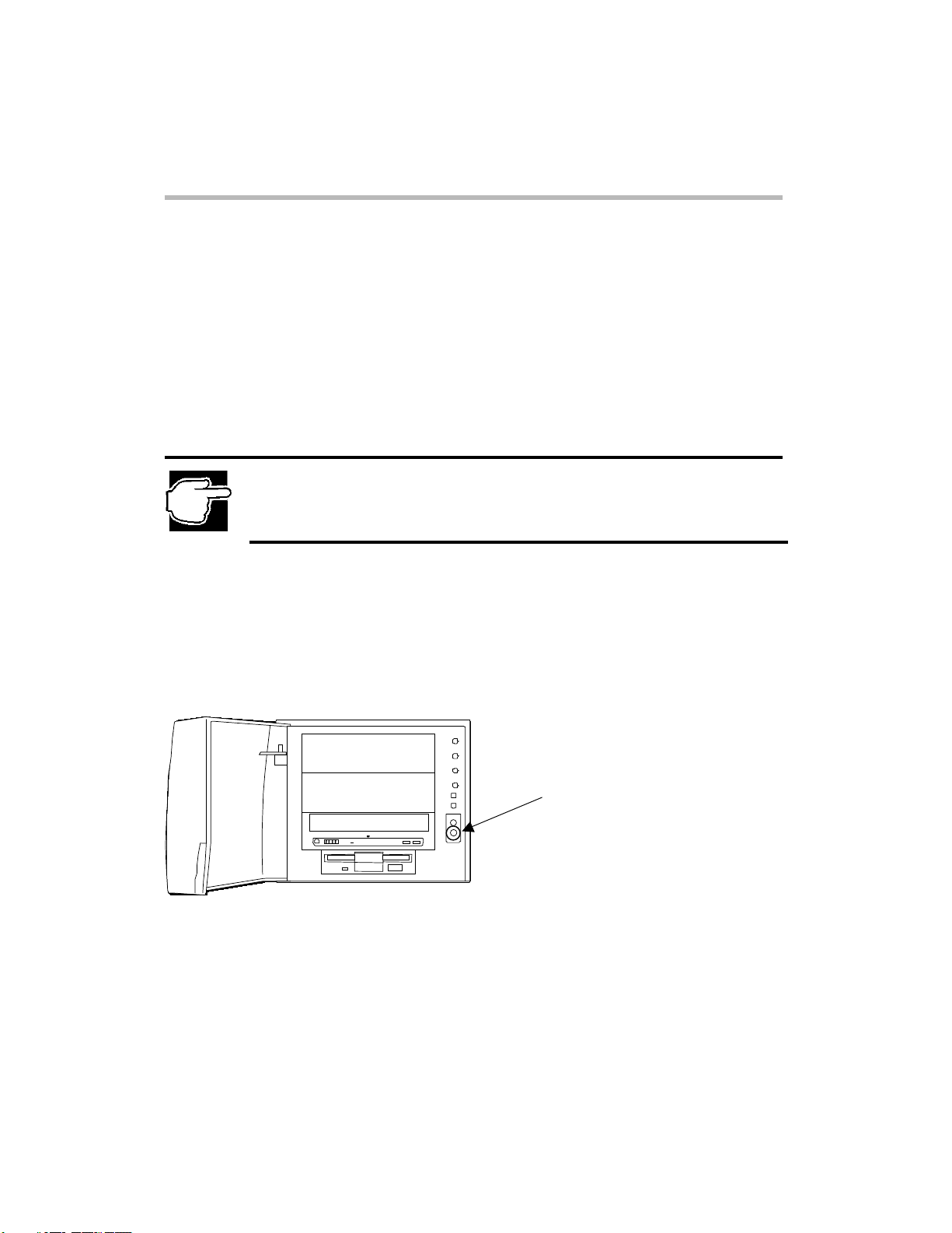
5. Turn on the Power switch on the computer front.
Power switch
MAGNIA3100 Front View
Page 7
6. When this message appears:
"Please insert the Server Setup TooL CD, then press any key."
Insert the SST CD-ROM and press any key.
7. After a while, the Toshiba Server Setup TooL Start-up screen is replaced
with the Main menu.
Server Setup TooL Start-up screen
Server Setup TooL
Starting t he server
2
Page 8
Server Setup TooL
Starting t he server
3
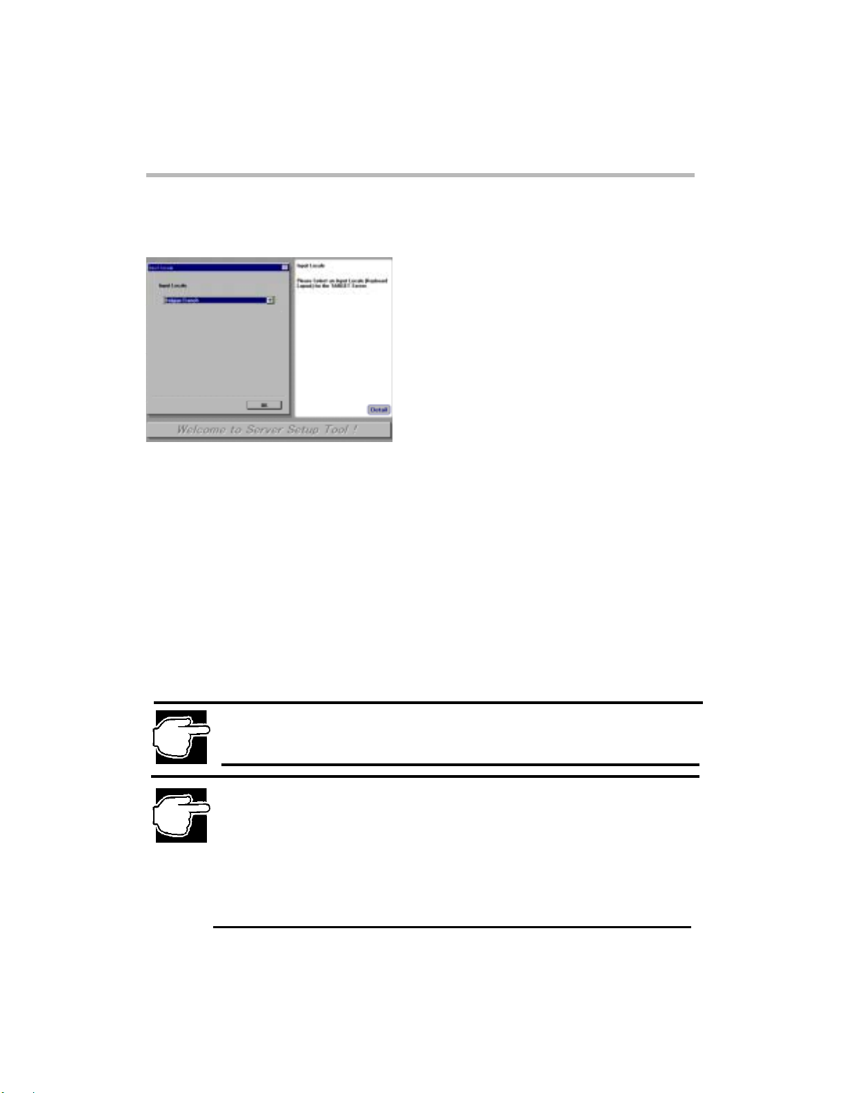
8. After the Server Setup TooL Start-up screen, the Input Locale screen appears.
Input Locale screen
Select one of the following keyboard layouts.
Ӎ Belgian French
Ӎ French
Ӎ
German
Ӎ Spanish
Ӎ Swi ss Fren c h
Ӎ Swiss German
Ӎ United Kingdom
Ӎ U.S.
NOTE: The Input Locale screen only appears when you start SST from the Startup Disk for the first
time. The Locale information you select will be recorded on the Startup Disk. Once recorded, the Input
Locale screen never appears when you start SST from the Startup Disk.
NOTE: To reconfigure the locale setting, you must record the locale setting on the Startup Disk by
procedure (1) or (2) listed below. Then, you can reinstall Windows 2000 Server / Windows NT Server
4.0 using SST automatic installation procedure.
(1) Create Startup Disk from [Utilities-Create Floppy Disks] and start SST on the server from the
Startup Disk and select locale setting.
(2) Start SST on another system and select locale setting, and then select [Utilities-Setup
Information] and click [Save] on the Confirm Parameter Settings screen. The locale setting will
be recorded on the Startup Disk. Start SST on the server from the Startup Disk.
Page 9
Starting SST on anot he r syste m
The Server Setup TooL ca n be started on systems running each of the operating systems listed below:
Windows 2000, Windows NT, Windows 98, Windows 95.
T o start the Server Setup TooL from another system(s):
1. Place the SST CD-ROM into the CD-ROM drive.
2. After the Input Locale screen appears, select one keyboard layout.
3. After finishing the locale setting, the SST Main menu appears.
NOTE: The Input Locale screen always appears when you start SST on another system. The locale
information that you selected will be recorded only when you select [Utilities-Setup Information] and
click [Save] on the Confirm Parameter Settings screen.
NOTE: When the Server Setup TooL has been started on another system, you can use only the
Utilities option in the Main menu.
If the Auto-Run function is not allowed, the Server Setup TooL can not be started on another system.
Starting SST on another system
Server Setup TooL
4
Page 10
5
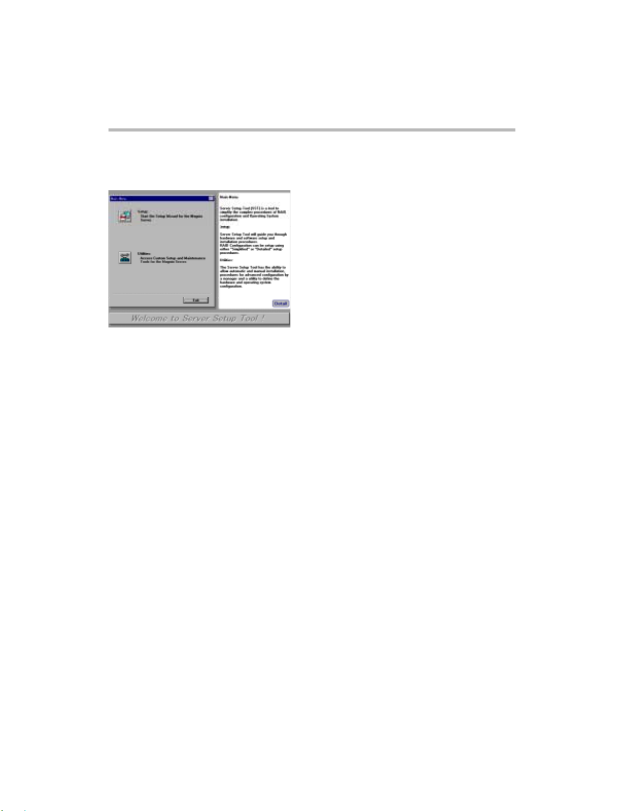
Main Menu
Main Menu scree n
Setup
The Setup option is designed to automate the installation of RAID and the operati ng system . You are
guided through a series of questions, and then the system is automatically configured and the
software is installed. For more information, see section [Setup] in Chapter 2.
Utilities
The Utilities option allows you to customize t he sy s tem installation, create diskettes , and manage the
RAID configuration. For more information, see section [Utilities] in Chapter 3.
Server Setup TooL
Main Menu
Page 11

Chapter 2
Page 12
Setup Wizard
RAID Configuration
After selecting a
the MR493, the MR475 or the MR466 RAID Controller exists.
Setup
option from the SST Main menu, the RAID Configuration screen appears only if
Setup
RAID Configuration
6
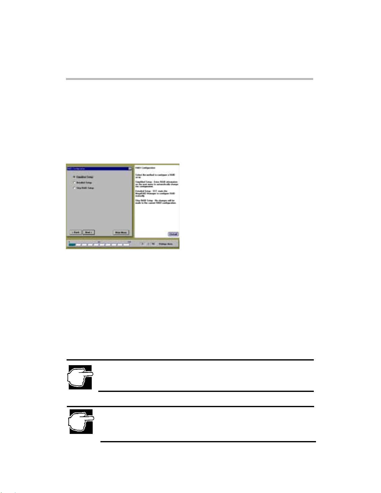
RAID Configuration screen
Simplifie d Se tup
This option allows you to input RAID type, Hot Spare option, and other RAID configuration
information.
Detailed Setu p
This option manually starts the RAID configuration utility, and then it allows you to manually
configure the array.
(For more information, refer to the MegaRAID User's Manual.)
Skip RAID Setup
Skips setting up the RAID device.
NOTE: If you are setting up the computer for the first time and a RAID array has not been configured,
use [Simplified Setup] or [Detailed Setup].
NOTE: If you want to setup a RAID configuration that is not possible by using [Simplified Setup],
(for example: multiple array groups, multiple MegaRAID adapters, RAID10, RAID50, etc.), select
[Detailed Setup].
For details about [Simplified Setup], click [Detail] and refer to Server Setup TooL Help.
Page 13
Setup
7
Simplified RAID Configura tion Setup
If you select the Simplified Setup option on the RAID Configuration screen,
the Simplified RAID Configuration Setup screen appears.
Simplified RAID Configuration Setup
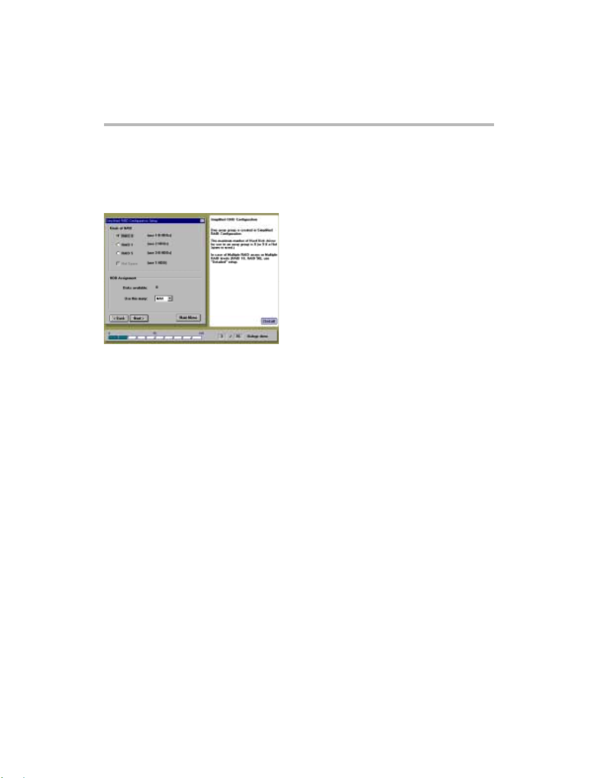
Simplified RAID Configuration Setup screen
RAID0 (One or more HDDs is required.)
Multiple HDDs are grouped and constructed as one unique logical device.
Data is recorded in a dispersed manner and the write and read performance of the HDDs is high .
RAID1 (Two HDDs are required.)
The HDDs are mirrored images of each other. The same data is always written to both HDDs.
Therefore, if one HDD is damaged, the operation can be continued by the other HDD.
RAID5 (Three or more HDDs are required)
Multiple HDDs are grouped and constructed as a single logical device. Data and parity are recorded
in the grouped HDDs in a dispersed manner. If one HDD is damaged, the operation can be continued
by the other HDDs.
Hot Spare (Can be used if RAID1 or RAID5 is selected.)
Hot Spare is a spare HD D in s tand-by ; w hen one HD D is dam aged, the ho t spa re automatica lly goes
on-line.
HDD Assignment
Select the number of HDDs for the RAID configuration from the list. When "MAX" has been
selected, the RAID array is structured with the maximum number of HDDs (= 6).
Page 14
Operating System Installation Selection
After selecting a Simplified RAID Configuration Setting option (if the MR493, the MR475 or the
MR466 RAID Controller exists), or selecting a
the MR475 or the MR466 RAID Controller does not exist), the Operating System Installation
Selection menu appears.
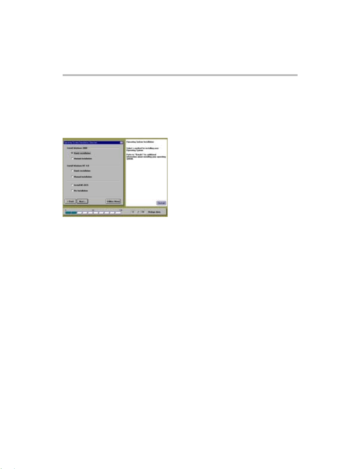
Operating System Installation screen
Install Windows 2000
Quick Installation
Guides you through a quick installation of Windows 2000 Server using Server Setup
TooL's automatic installation procedure.
Manual Installation
Allows you to perform a manual installation of Windows 2000 Server. The necessary
Diskettes for manual installation will be automatically created .
Install Windows NT 4.0
Quick Installation
Guides you through a quick installation of Windows NT 4.0 Server using Server
Setup TooL's automatic installation procedure.
Manual Installation
Allows you to perform a manual installation of Windows NT 4.0 Server. The necessary
Diskettes for manual installation will be automatically created .
Install MS-DOS
Allows you to install MS-DOS for installation of the NetWare. To install the NetWare, create
the necessary diskettes for NetWare installation in the Utility menu first.
No Installation
Skips the operati ng system installation process.
Operating S y s tem Installa ti on Selection
Setup
option from the SST Main menu (if the MR493,
Setup
8
Page 15
9
Setup
Operating S y s tem Installa ti on Selection
NOTE: If you want to install Windows 2000 Server or Windows NT Server 4.0 without using SST,
create the necessary diskettes for installation in the Utility menu first.
Refer to following.
Ӎ
[Chapter 2 – Windows 2000 Manual Installation without using SST] (Windows 2000)
Ӎ
[Chapter 2 – Windows NT Manual Installation without using SST] (Windows NT)
Ӎ
The MAGNIA3100 User's Guide
NOTE: If you selected [Install MS-DOS], the Server Setup TooL will create a disk partition (from 50MB
to 2,048MB). To install the NetWare after installing MS-DOS, refer to the MAGNIA 3100 User's Guide.
Page 16
Windows 2000 Quick Installation
Locale Settings
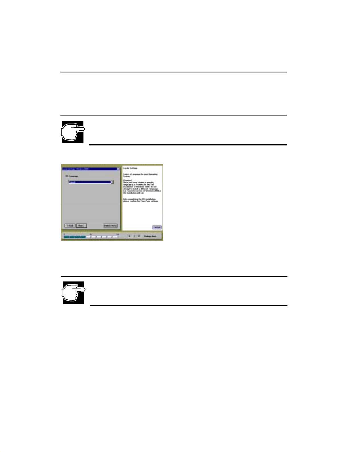
NOTE: When you select the "Install Windows 2000 – Quick installation" option, the following Locale
Settings screen appears.
Setup
Locale Settings (Windows 2000 Quick Installation)
10
Locale Settings screen
Select a Language for your Operating System.
NOTE: You must select the same OS language as your OS CD-ROM. Once you have chosen a
specific language [i.e. French] for the SST installation of Windows 2000, do not attempt to install a
different language [i.e. Spanish] version of Windows 2000 or the installation will fail.
Page 17
11
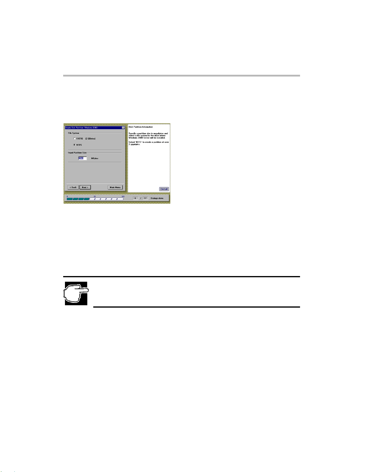
Create Disk Partition
After sp ecifying the Locale Settings, the Cr eate Disk Partition screen appear s.
Create Disk Partition screen
Select a file system.
FAT16
Creates the file system using the FAT16 (File Allocation Table with 16-bit entries) format.
NTFS
Creates the file system using the NTFS (NT File System) format.
Setup
Create Disk Partition (Windows 2000 Quick Installation)
NOTE: If you select "FAT16", SST will create the partition as 2048MB size.
If you select "NTFS" and enter a partition size larger than one available on the disk, SST will create the
partition as 2048MB size default.
Input Partition Size
Enter the size of the disk partition you want to create, then press [Enter].
Page 18
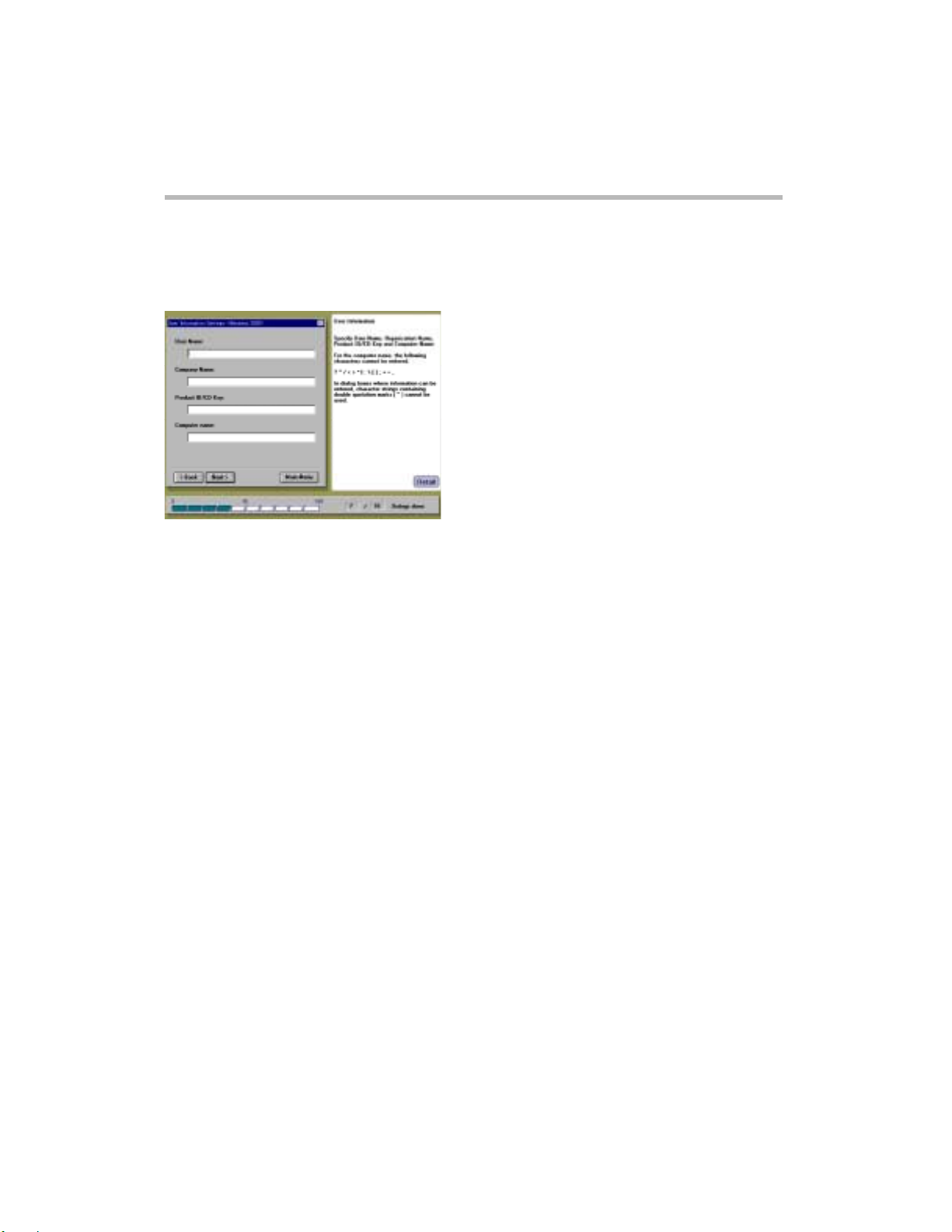
User Information Settings
After specifying the disk partition parameters, the User Information Settings screen appears.
User Information Settings screen
Enter the following user settings:
User Name
Name of the user (a dministrator).
Company Name
Company or organization name (optional).
Product ID/CD Key
Product ID or CD-key of the Windows 2000 Server CD-ROM.
Computer Name
Identifies the computer to the rest of the network. The identifying name should be 15
alphanumeric characters or less.
User Information Settings (Windows 2000 Quick Installation)
Setup
12
Page 19
13
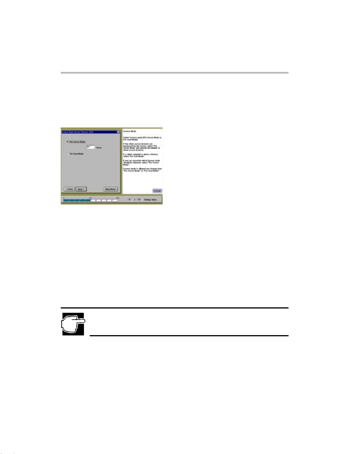
License Mode Setting
After specifying the User Information Settings, the License Mode Setting screen appears.
Setup
License Mode Setting (W indows 2000 Quick Installation)
License Mode Setting screen
You can structure the operating system license in one of two ways:
Per Server Mode
The server's license specifies the number of clients.
The number of users for a server should be no less than the number of client computers that can
simultaneously connect to that server.
Per Seat Mode
Each client computer (seat) has its o wn license, which a llows it to acc ess any Windows 2000 Server on the
network.
Select one of the two license modes and click [Next] after the setting.
NOTE: If you are not sure which license mode to use, select "Per Server Mode". The license mode can
be changed once only from "Per Server Mode" to "Per Seat Mode", based on the contract for the
license.
Page 20
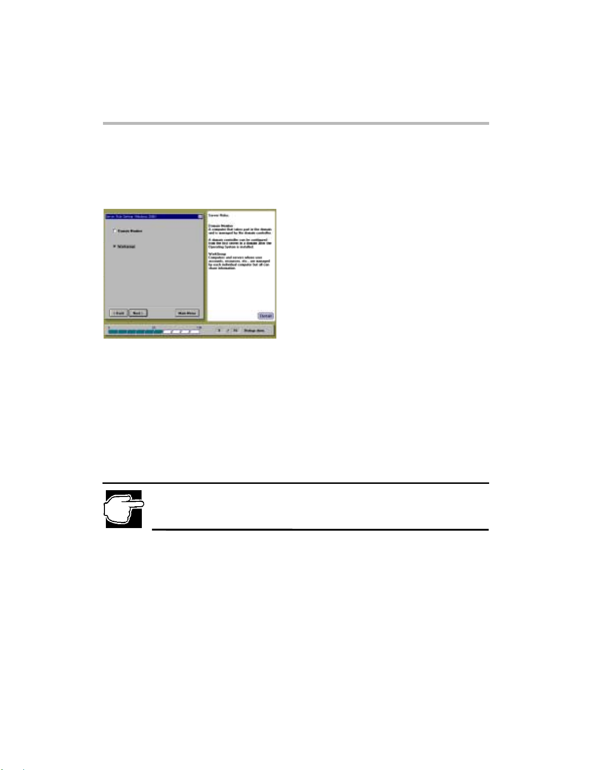
Server Role Setting
After specifying the License Mode Setting, the Server Role Setting screen appears.
Server Role setting screen
Select one of the options, then click [Next].
Domain Member
Configures the computer as part of the domain, controlled by a domain controller.
Workgroup
User accounts and resources are controlled by the individual computers.
Server Role Setting (Windows 2000 Quick Installation)
Setup
14
NOTE: To make your server a domain controller, you must install Active Directory after the Windows
2000 Server installation. See section [After Installation (Windows 2000)] in Chapter 2.
Page 21
Setup
15
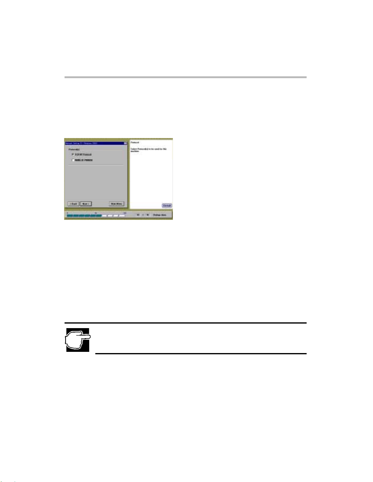
Network Setting [1 ]
After specifying the Server Role, the Network Setting [1] screen appears. Use this screen to specify
the ne twork c ommuni cation protocol.
Network Setting [1] screen
Select the communication protocol being used, then click [Next].
TCP/IP Protocol
Send communication protocol
Internet protocol
NetBEUI Protocol
NetBIOS expansion user interface
Network Setting [1] (Windows 2000 Quick Installation)
NOTE: If you select "TCP/IP Protocol", the SNMP service will be automatically installed.
Page 22
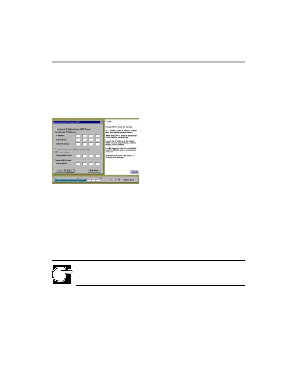
Network Setting [2]
After you have specified TCP/IP as the n etwork communication protocol, the Network Setting [2] screen
appears. The Network Setting [2] screen allows you to specify the IP Address, Subnet Mask, Default
Gateway Address, Primary DNS Server Address, and Primary WINS Server Address for your computer.
Network Setting [2] screen
T o s et up the network communication protocol, complete o ne of the following steps to specify the IP
Address for your computer:
1. To have the domain server automatically assign the IP addresses, Subnet Masks and
Default Gateway to your computer, select "Assign IP Address from DHCP Server".
2. If you are using the Windows Inter net Name Se rvice (WI NS), in the Primary WINS S erver pane,
enter the IP address for your Primary WINS Server.
NOTE: For IP Address, Subnet Mask, Default Gateway Address, Primary DNS Server and Primary
WINS Address, you must use decimal numbers (from 0 to 255).
Network Setting [2] (Windows 2000 Quick Installation)
Setup
16
Page 23
Setup
17
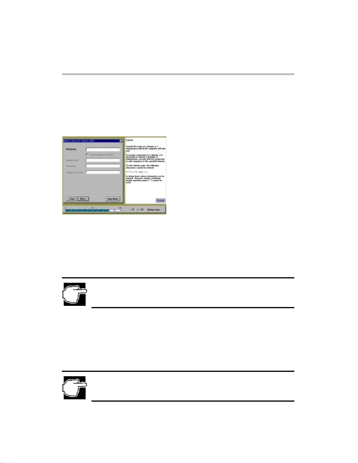
Network Setting [3 ]
After you h a ve s p ec i fi ed t he IP addresses for you r co mpu t e r, the Net w or k Set ting [3] scr een ap pe ars. Use
this screen to specify the name of the domain or workgroup in which your computer takes part.
Network Setting [3] screen
To specify the domain or workgroup to which your computer belongs:
1.
Enter the name of a domain or a workgroup. To make this server a part of a domain for the first time,
select [Create Computer Account].
2.
If the server has already been registered for the domain or you want to make this server a part of the
workgroup, click [NEXT].
3.
In the Administrator text box, enter the name of the manager or administrator account that has the
permission to add computers to the specified domain.
4.
In the Password text box, enter the password of the domain manager account.
5.
In the Confirm Password text box, reenter the password to confirm it.
Network Setting [3] (Windows 2000 Quick Installation)
NOTE: If the server has already been registered for the domain, or you want to make this server a part
of the workgroup, it is not necessary to create the computer account.
NOTE: Do not use double-quote marks (") for all items.
Page 24
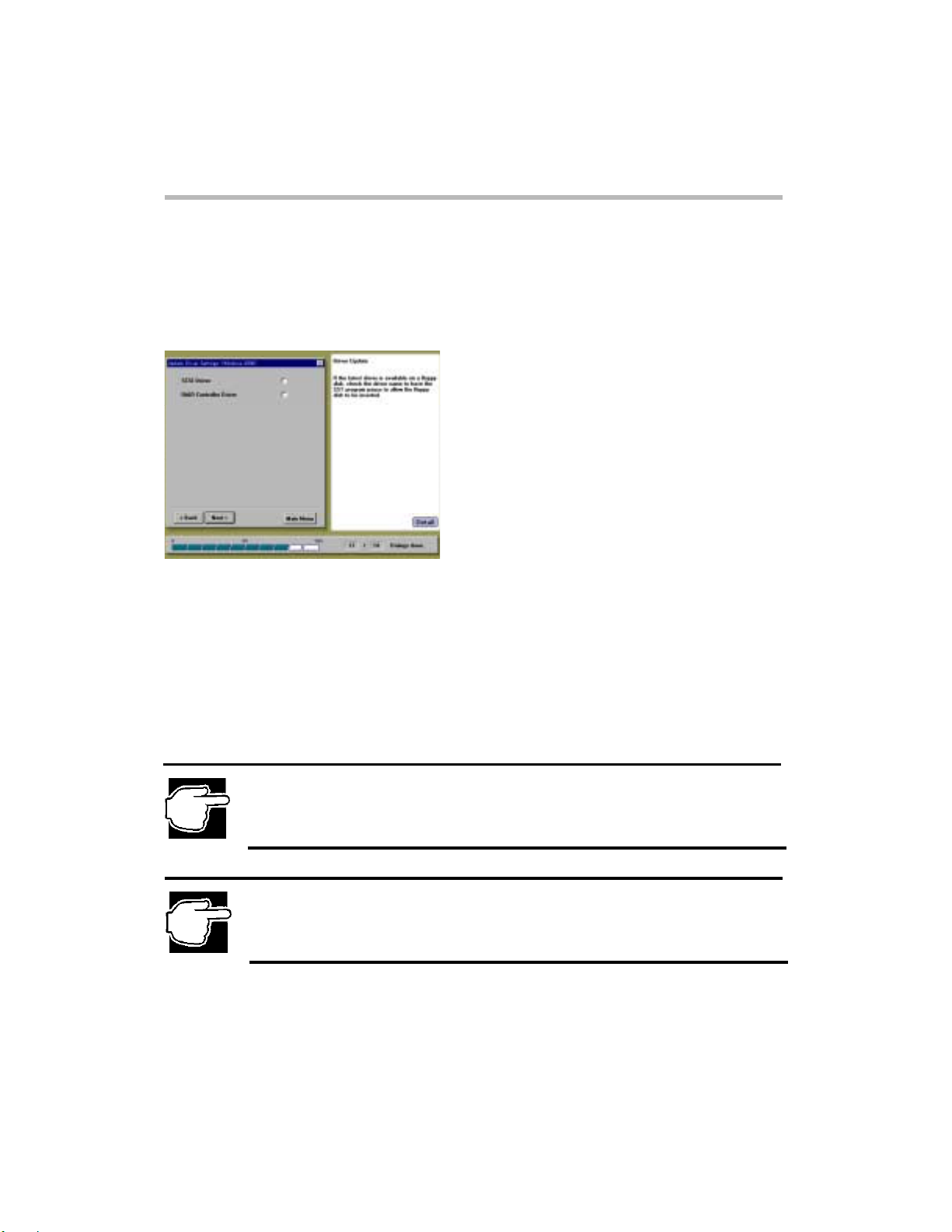
Update Driver Se tti ngs
After the network settings screen, the Update Driver Settings screen appears.
Update Driver Settings screen
SCSI Driver
Update Driver Settings (Windows 2000 Quick Installation)
Setup
18
Driver for SCSI controller
RAID Controller Driver
Driver f o r RA ID contr o l ler ( i f th e M R493 or th e M R47 5 R AI D C ontrolle r is n o t in s ta l led o n your
computer, this item will be grayed out.)
NOTE: The drivers for the server hardware are on the Server Setup TooL CD-ROM. You may, however,
have installed equipment that was shipped with newer drivers on diskettes. If you need to use the
drivers on diskettes, continue with this section. If you wish to use the drivers from the CD-ROM,
proceed to the next step by clicking [NEXT].
NOTE: If you select the "SCSI Driver” or the “RAID Controller Driver”, the list of devices will be shown
on the screen, after setting the driver diskette. You must select correctly one of the devices from the
list. Refer to the MAGNIA3100 user’s guide and the MegaRAID User’s Manual for information about
the device name.
Page 25

Setup
19
Services and Ap plication Installa ti on
Clicking
screen only if the MR493 or the MR475 RAID Controller exists.
Services and Application Inst allati on (Windows 2000 Q u ick Inst a llatio n)
Next
on the Update Driver Settings screen disp lays the Services and Application Installation
Services and Application Installation screen
AMI RAID Utility
The AMI RAID Controller utility:
Power Console
Monit ors the RAID configuration.
Service
Extracts log information.
SNM P Agent
Used by TCP/IP-based management applications.
Select the following options:
To install each application automatically, check the [Install] box.
To install each application driver from the diskette or the CD-ROM, check the [From FD/CD] box.
Page 26

Services and Application Inst allati on (Windows 2000 Q u ick Inst a llatio n)
NOTE: If you have the latest version on the diskette or the CD-ROM, check [From FD/CD]. If you do
not select "TCP/IP protocol" (then SNMP service is also not installed), the SNMP agent of AMI RAID
utility cannot be installed.
NOTE: For the AMI MR466 RAID Controller, if you want to install the AMI RAID Utility, you must install
the utility manually after Windows 2000 Server installation. See [Chapter 2 – After Installation
(Windows 2000)] and the MegaRAID User's Manual.
Setup
20
Page 27

Setup
21
Setup Option
After you have specifi ed the install ation options for Service s and Ap plication (i f the MR493 or t he
MR475 RAID Controller exists) or Update Driver Settings (if the MR493 or the MR475 RAID
Controller does not exist), the Setup Option screen appears. Use this screen to specify the setup
installation features you want enabled during the installation pr ocess.
Setup Option screen
Beep sound in ca se of disk change
Sounds an audible alert (beep) to change storage media (CD-ROM and diskette).
Start installation according to parameter settings at boot time
The next time the SST start s, the installati on automatical ly begins after a confirmation message,
using the configuration information currently stored on the Startup Disk.
have not been installed yet, their device drivers will not be installed.
selected, the SST starts normally at the Main Menu.
Confirm part ition information during installat ion pr ocedure
A dialog box appears, requiring you to confirm the deletion of the existing partition.
If a disk partition already exists, a confirmation message appears, asking if you want to delete the
partition. If this option is not checked, setup deletes the partition without prompting you for
confirmation.
Setup Option (Windows 2000 Quick Installation)
If the necessary devices
If this option is not
NOTE: If you have an existing partition (such as Windows 2000, Windows NT or NetWare), the
partition is deleted first before installation.
Page 28

Confirm Parameter Settings
After you have specified setup installation features, the Confirm Parameter Settings screen appears. This
screen displays a window listing the configuration and setup parameters that you have chosen.
Confirm Parameter Settings screen
Review the information displayed on the Confirm Parameter Settings screen to make sure that it is
accurate. To change a setting, highlight the item you wish to change and click
wizard will return to that screen and allow you to make changes.
If you are satisfied w ith the installation settings, c lick
Confirm Parameter Settings (Windows 2000 Quick Installation)
Execute
.
Setup
Jump
22
. The setup
Page 29

Setup
23
Windows NT 4.0
Quick Installation
Locale Settings
Locale Settings screen
Select a Language for your Operating System.
Locale Settings (Windows NT 4.0 Quick I nst al la tion)
NOTE: When you select the “Install Windows NT – Quick installation” option, the following Locale
Settings screen appears.
NOTE: You must select the same OS language as your OS CD-ROM. Once you have chosen a
specific language [i.e. French] for the SST installation of Windows NT, do not attempt to install a
different language [i.e. Spanish] version of Windows NT or the installation will fail.
Page 30

Create Disk Partition
After sp ecifying the Locale Settings, the Cr eate Disk Partition screen appear s.
Create Disk Partition screen
Select one of the following options:
FAT16
Creates the file system using the FAT16 (File Allocation Table with 16-bit entries) format. FAT 16
limits the size of any given disk drive (such as a drive D) to 2GB.
NTFS
Creates the file system using the NTFS (NT File System) format. NTFS limits the size of the disk
drive to 2GB.
NTFS Expansion
Creates the file system using the NTFS form at, with an expansion to incr eas e the size of the partition. This
increases the limit on the disk device to 8GB.
In the Input Partition Size text box, enter the size of the disk partition you want to create.
NOTE: If you select "NTFS Expansion", the partition size that you entered is ignored. If you do not
select "NTFS Expansion", you can enter the partition size from 512MB to 2048MB.
NTFS Expansion uses the entire remaining disk space to create the partition.
Create Disk Parti tion (Windows NT 4.0 Quick Installation)
Setup
24
Page 31

Setup
25
User Information Settings
After specifying the disk partition parameters, the User Information Settings screen appears.
User Information Settings (Windows NT 4.0 Quick Installation)
User Information Settings screen
Enter the following user settings:
User Name
Name of the user (a dministrator).
Company Name
Company or organization name (optional).
Product ID/CD Key
Product ID or CD-key of the Wi n dows NT S erver 4. 0 CD-ROM.
Computer Name
Identifies the computer to the rest of the network. The identifying name should be 15 alphanumeric
characters or less.
Page 32

License Mode Setting
After specifying the User Information Settings, the License Mode Setting screen appears.
License Mode Setting screen
You can structure the operating system license in one of two ways:
Per Server Mode
Licens e M od e Setting (Windows NT 4.0 Quick Inst al l a t ion)
Setup
26
The server's license specifies the number of clients.
The number of users for a server should be no less than the number of client computers that can
simultaneously connect to that server.
Per Seat Mode
Each client computer (seat) has its own license, which allows it to access any Windows NT server on the
network.
Select one of the two license modes and click [Next] after the setting.
NOTE: If you are not sure which license mode to use, select "Per Server Mode". The license mode can
be changed once only from "Per Server Mode" to "Per Seat Mode", based on the contract for the
license.
Page 33

Setup
27
Server Role Setting
After specifying the License Mode Setting, the Server Role Setting screen appears.
Server Role Setting (Windows NT 4.0 Quick Installation)
Server Role Setting screen
The Server Role Setting screen allows you to specify the role your computer plays within the network
(domain).
Select the server's role from one of the following options, then click [Next].
Primary Domain Controller
Configures the computer to manage the domain.
Backup Domain Controller
Configures the computer to synchronize with the primary domain controller as a backup server. As a
backup server, the computer stores a copy of the security database on its hard disk drive. I t also can assume
the role of the primary domain controller, when necessary.
Domain Member
Configures the computer as part of the domain, controlled by a domain controller.
Workgroup
User accounts and resources are controlled by the individual computers.
Page 34

Network Setting [1 ]
After you hav e speci fied th e server ro le, the Net work Set ting [ 1] screen appears. This is the sc reen
where you specify the network setup method.
Network Setting [1] screen
Select one of the following network settings, then click [Next].
Simplified Se tti ng
Allows you to set up a protocol and domain or workgroup manually. The LAN driver is
automatically installed, and existing service settings are set up.
Detailed Setting
SST will stop the auto install at the point where the Windows NT Server 4.0 setup program accepts the user
input. After the user's input ends, the process continues.
NOTE: If you select the "Detailed Setting", proceed to [Chapter 2 - Update Driver Settings (Windows
NT 4.0 Quick Installation].
Network Setting [1] (Windows NT 4.0 Quick Installation)
Setup
28
Page 35

Setup
29
Network Setting [2 ]
After selecting
Use this screen to specify the network communication protocol.
Network Setting [2] screen
Select the communication protocol being used.
TCP/IP Protocol
Send communication protocol
Internet protocol
NetBEUI Protocol
NetBIOS expansion user interface
Network Setting [2] (Windows NT 4.0 Quick Installation)
Simplified Setting
NOTE: If you selected "Simplified Setting" and select "TCP/IP Protocol", the SNMP service will be
automatically installed.
from Network Setting [1], the Network Setting [2] screen appears.
Page 36

Network Setting [3 ]
After you have specified TCP/IP as the network communication protocol, the Network Setting [3] screen
appears. The Network Setting [3] screen allows you to specify the IP Address, Subnet Mask, Default
Gateway Address and Primary WINS Address for your computer.
Network Setting [3] screen
To set up the network communication protocol:
1.
Complete one of the following steps to specify the IP Address for your computer:
To have the domain server automatically assign the IP addresses, Subnet
Masks and Defaul t Ga teway to your comput e r , select "Assign IP Addr e ss
from DHCP Server".
T o sp e cify the server's IP Addr e ss, Subnet Mask, and Default Gateway
Address, do not select "Assign IP Address from DHCP Server" and enter the
addresses described above.
2. I f you are using the Windows Internet Name Service (WINS) in the Primary WINS Server pane,
enter the IP address for your Primary WINS Server.
NOTE: For IP Address, Subnet Mask, Default Gateway Address, Primary WINS Address, you must
use decimal numbers (from 0 to 255).
Network Setting [3] (Windows NT 4.0 Quick Installation)
Setup
30
Page 37

Setup
31
Network Setting [4 ]
After you have specified the IP addresses for your computer, the Network Se tting [4] screen appears.
Use this screen to specify the name of the domain or workgroup in which your computer takes part.
Network Setting [4] screen
To specify the domain or workgroup to which your computer belongs:
1. In the domain Name text box, enter the name of the domain or workgroup for your network. To
make this server part in the domain for the first time, select [Create Computer Account].
2. If the server has already been registered for the domain, or you want to make this server a part of
the workgroup, click [Next].
3. In the Administrator text box, enter the name of the manager or administrator account that has
permission to add computers to the specified domain.
4. In the Password text box, enter the password of the domain manager account.
5. In the Confirm Password text box, reenter the password to confirm it.
Network Setting [4] (Windows NT 4.0 Quick Installation)
NOTE: If the server has already been registered for the domain, or you want to make this server a part
of the workgroup, it is not necessary to create the computer account.
NOTE: Do not use double-quote marks (") for all items.
Page 38

Update Driver Se tti ngs
After the network settings screen, the Update Driver Settings screen appears.
Update Driver Settings screen
Update Driver Settings (Windows NT 4.0 Quick Installation)
Setup
32
NOTE: The drivers for the server hardware are on the Server Setup TooL CD-ROM. You may, however,
have installed equipment that was shipped with newer drivers on diskettes. If you need to use the
drivers on diskettes, continue with this section. If you wish to use the drivers from the CD-ROM,
proceed to the next step by clicking [NEXT].
SCSI Driver
Driver for SCSI controller
RAID Controller Drive r
Driver for RAID controller (if the MR493, the MR475 or the MR 466 RAID Controller is not
installed on your computer, this item will be grayedout.)
LAN Driver
Driver for Network adapter
NOTE: If you select the "SCSI Driver” or the “RAID Controller Driver”, the list of devices will be shown
on the screen, after setting the driver diskette. You must select correctly one of the devices from the
list. Refer to the MAGNIA3100 user’s guide and the MegaRAID User’s Manual for information about
the device name.
Page 39

Setup
33
Services and Ap plication Installa ti on
Clicking
screen only if the MR493, the MR475 or the MR466 RAID Controller exists.
Services and Application Installation screen
AMI RAID Utility
The AMI RAID Controller utility:
Power Console
Monit ors the RAID configuration.
Services an d Applicat i o n Installation (Windows NT 4 .0 Quick Installation)
Next
on the Update Driver Settings screen disp lays the Services and Application Installation
Service
Extracts log information.
SNM P Agent
Used by TCP/IP-based management applications.
Select the following options:
To install each application automatically, check the [Install] box.
To install each application driver from the diskette or the CD-ROM, check the [From FD/CD] box.
NOTE: If you have the latest version on the diskette or the CD-ROM, check [From FD/CD]. If you do
not select "TCP/IP protocol" (then SNMP service is also not installed), the SNMP agent of AMI RAID
utility cannot be installed.
Page 40

Setup Option
After you have specified the installation options for Services and Application (if the MR493, the MR475 or
the MR466 RAID Controller exists) or U pdate Dri ver Settings (if t he MR493, th e MR475 or th e MR466
RAID Controller does not exist), the Setup Option screen appears. Use this screen to specify the setup
installation features that you want enabled during the installation process.
Setup Option screen
Select any of the following features that you want to activate:
Beep sound in ca se of disk change
Sounds an audible alert (beep) to change storage media (CD-ROM and diskette).
Start installation according to parameter settings at boot time
The next time the SST starts, installation automatically begins after a confirmation message, using the
configuration information currently stored on the Startup Disk.
installed yet, their device drivers will not be installed.
normally at the Main Menu.
Confirm partition information during installation procedure
A dialog box appears requiring you to confirm the deletion of the existing partition.
If a disk partition already exists, a confirmation message appears ask ing if you want to delete the partition.
If this option is not checked, setup deletes the partition without prompting you for confirmation.
NOTE: If you have an existing partition (such as Windows 2000, Windows NT or NetWare), the
partition is deleted first before installation.
Setup Option (Windows NT 4.0 Quick Installation)
If the necessary devices have not been
If this option is not selected, the SST starts
Setup
34
Page 41

Setup
35
Confirm Parameter Settings
After you have specified setup installation features, the Confirm Parameter Settings screen appears. This
screen displays a window listing the configuration and setup parameters that you have chosen.
Confirm Parameter Settings screen
T o initiate the installation process :
1. Review the information displayed on the Confirm Parameter Settings screen to make sure
that it is accurate. To change a setting, highlight the item you wish to change and click
wizard will return to that screen and allow you to make changes.
2. If you ar e satisf ied with the in stallation s etting s, click
Confirm Parameter Settings (Windows NT 4.0 Quick Installa tion)
Execute
.
Jump
. The setup
Page 42

Windows 2000
Manual Installation
using SST
When [Install Windows 2000 - Manual Installation] is selected from the [Operating System
Installation Selection] menu, the RAID system is automatically configured, and the diskettes for
manual installation are automatically created. For more information about Windows 2000 installation,
refer to the MAGNIA3100 user's guide.
The diskettes SST automatically creates are listed below:
- Symbios Windows 2000 Driver <Windows 2000 >
Windows NT 4.0
Manual Installation
using SST
When [Install Windows NT 4.0 - Manual Installation] is selected from the [Operating System
Installation Selection] menu, the RAID system is automatically configured, and the diskettes for
manual installation are automatically created. For more information about Windows NT Server 4.0
installation, refer to the MAGNIA3100 user's guide.
The diskettes SST automatically creates are listed below:
- Symbios Windows NT Driver <Windows NT>
- Intel LAN Windows NT Driver <Windows NT>
W indows 2000 Manual Installation using SST
Setup
36
Page 43

Setup
37
Windows 2000 / Windows NT 4.0
Manual Installation
without using SST
To install the Windows 2000 Server or Windows NT Server 4.0 without using the Toshiba Server
Setup To oL's automatic installat ion procedure, you must create some diskettes for manual installatio n
from the "Create Floppy Disks" menu. After creating the diskettes, follow your MAGNIA 3100
User's Guide installation instructions.
Create Floppy Disks for Manual Installation
1. Insert the SST Startup Disk.
2. Turn on the server.
3. When this message appears:
"Please insert the Server Setup TooL CD, then press any key."
Insert the SST CD-ROM and press any key.
4. Server Setup TooL starts.
5. Select the [Utilities] option in the "Main Menu".
Utility Menu screen
W indows 2000 / W indows NT 4.0 Manual Installation without using SST
Page 44

6. Select [Create Floppy Disks] option and following items, then select [Create].
- Symbios Windows 2000 Driver <Windows 2000>
- Symbios Windows NT Driver <Windows NT>
- Intel LAN Windows N T Driver <Windows NT>
Create Floppy Disks screen
7. Insert an unused diskette, then select [OK].
(if necessary, remove the Startup Disk.)
8. After creating the diskettes, you must label the diskettes. To check the label descriptions,
select [Detail] [Create Floppy Disks] and see the SST Help.
- (FD label: Symbios Windows 2000 Driver) <Windows 2000>
- (FD label: Symbios Windows NT Driver) <Windows NT>
- (FD label: Intel EtherExpress PRO/100+ LAN Adapter Configuration and Drivers
(W indows 2000 / W indows NT 4.0 Manual Installation without using SST)
Diskette Windows NT) <Windows NT>
Create Floppy Disks for Manual Installation
Setup
38
Page 45

Setup
39
After Installation
(Windows 2000)
If you have finished Windows 2000 Server installation, then follow the steps below:
Confirming and Setting up t he Time Zone
1. Start Windows 2000 Server and log onto it as the Administrator (or a user having
equivalent rights).
2. Run Date/Time Properties by clicking
double clicking on
3. Click
4. Check that the current Time Zone setting is correct. If incorrect, select the correct
setting and press [OK].
Setting up the AMI RAID utility (MR466 RAID Controller only)
If the MR466 RAID Controller exists on your server and you want to use the AMI RAID utility
(Power Console, Service, SNMP Agent), you must install it manually after the Windows 2000
Server installation.
To install the AMI RAID utility, follow your MegaRAID User's Manual.
Setting up the Active Directory (To make this server as a domain controller)
If you installed TCP/IP protocol and you want to designate this server as a domain controller in
your network, you must install Active Directory.
For more information about Active Directory, refer to the Windows 2000 Server Help.
After Installation (Windows 2000)
Time Zone
Date/Time
tab.
.
Start, Settings, Control panel
, and
Page 46

After Installation
(Windows NT 4.0)
If you have finished Windows NT Server 4.0 installation, then follow the steps below:
Confirming and Settin g up t he Time Zone
1. Start Windows NT Server 4.0 and log onto it as the Administrator (or a user having equivalent rights).
2. Run Date/Time Properties by clicking
Date/Time
3. Click
4. Check tha t the current Time Zone setti ng is correct . If i ncorr ect, se lect the c orrect se tting and p ress
[OK].
Selecting the display driver
If you want to display with SVGA mode or above, you must change the video driver from the
retai l driver in cluded in the Windows N T CD-RO M to the vid eo drive r includ e d in the SST
CD-ROM. Before changing the display driver, you must install the Windows NT Service Pack
(above Service pack 3).
After Windows NT Service Pack installation, follow the steps below:
1. Start Windows NT Server 4.0, and log onto Windows NT Server 4.0 as the Administrator (or
a user having equivalent rights).
2. Insert the SST CD-ROM.
3. Start the Explorer. (if following option is checked, then uncheck it.)
4. Change the current directory to:
Double-click SETUP.EXE.
5. When "Welcome" window appears, click [Next>].
6. When "Software License Agreement" window appears, read the contents carefully and click
[Yes].
7. When "Setup Complete" window appears, check the [Yes, I want to restart my computer
now.] option and click [Finish].
(Windows NT Server 4.0 restarts.)
8. After Windows NT Server 4.0 restarts, log onto the system, and the Display Properties
window appears. Modify the settings as desired.
.
Time Zone
[View] - [Options] - [Hide file extensions for known file types]
<CD-ROM>\PUBLIC\VIDEO\ATI\RAGEXL\NT
tab.
Start, Settings, Control panel
After Installation (Windows NT 4.0)
Setup
40
, and double clicking on
Page 47

Chapter 3
Page 48

H
41
How to Start Utilities
About Utilities
The utilities option allows you to customize the installation, create the diskettes, and manage the RAID
configuration. The Utilities Menu screen contains two panes, providing the following utilities:
Setup Support
- Setup Information
- Create Floppy Disks
HW Setup
- RAID Configuration
Utilities
ow to Start Utilities
NOTE: There are two ways to start the Utilities. Some utility programs cannot be executed according to
either way. Items which are grayedout cannot be executed.
Starting the Utilities program from SST CD-ROM with the Startup Disk
1. Insert the SST Startup Disk.
2. Turn on the server.
3. When this message appears:
"Please insert the Server Setup TooL CD, then press any key."
Insert the SST CD-ROM and press any key.
4. The Server Setup TooL starts the Main Menu, and then you can select the [Utilities] option.
Selectable items when the Utilities is started from SST CD-ROM with Startup Disk
Select able items
Setup Information
Create Floppy Disks
RAID Configuration
Utilit y Menu screen (s tarted from the Startup Disk)
Page 49

Starting the Utilities on another system
1. Insert the SST CD-ROM on the machine where Windows 2000, Windows NT,
Windows 98 or Windows 95 is running.
2. After a while, the Input Locale screen appears, then select one of the keyboard layout.
3. After finishing the locale setting, the SST Main menu appears.
Selectable items when the Utilities is started from another system
Starting the Utilities on another system
Select able items
Setup Information
Create Floppy Disks
Utilities
42
Utility Menu screen (started from anot her system)
NOTE: When the Server Setup TooL has been started on another system, only the Utilities of the Main
menu can be selected. If the Auto-Run function is not allowed, the Server Setup TooL does not start on
that system.
NOTE: The Input Locale screen always appears when you start SST on another system. Locale
information you select will be recorded only when you select [Utilities-Setup Information] and click
[Save] on the Confirm Parameter Settings screen.
Page 50

Utilities
43
Utility Menu
Setup Support
Setup Information
Clicking [Setup Information] starts the Setup Information wizard and opens the Setup Wizard dialog box
where you can make the choices for how SST configures the server, RAID, and operating system during
the installation procedure. This menu reads the current setting information from the SST Startup Disk and
arranges the settings.
Utility Menu
NOTE: To save the setup information you create on a Startup Diskette, click [Save] on the Confirm
Settings page.
NOTE: The Input Locale screen only appears once when you start SST from the Startup Disk for the
first time. Locale information that you selected will be recorded on the Startup Disk. Once recorded, the
Input Locale screen never appears when you start SST from the Startup Disk.
NOTE: To reconfigure the locale setting, you must record the locale setting on Startup Disk by
procedure (1) or (2) listed below. Then, you can reinstall Windows 2000 Server / Windows NT Server
4.0 using SST automatic installation procedure.
(1) Create Startup Disk from [Utilities-Create Floppy Disks] and start SST on the server from the
Startup Disk and select locale setting.
(2) Start SST on another system and select locale setting, and then select [Utilities-Setup
Information] and click [Save] on the Confirm Parameter Settings screen. The locale setting will
be recorded on the Startup Disk. Start SST on the server from the Startup Disk.
NOTE: The Input Locale screen always appears when you start SST on another system. Locale
information you select will be recorded only when you select [Utilities-Setup Information] and click
[Save] on the Confirm Parameter Settings screen.
Page 51

Create Floppy Disks
Clicking [Create Floppy Disks] lists the system boot, diagnostic, and installation diskettes you can create
from the Utilities menu.
NOTE: If you start the Utility menu from another system, you must start to create the diskettes after
selecting [Control Panel] – [Console] – [Screen Option] then set to [Full Screen].
Create Floppy Disks
Utilities
44
Create Floppy Disks sc reen
Page 52

45
There are the following check boxes in the Create Floppy Disks screen.
Checking the box lists the relative diskette titles in the menu.
Windows 2000
Lists the diskette titles that are necessary for installing the Windows 2000 Server.
Windows NT
Lists the diskette titles that are necessary for installing the Windows NT Server 4.0.
OTHER
Lists all diskette titles except ones for Windows 2000 Server and Windows NT Server 4.0.
Available Diskettes
The following diskettes can be created from the "Create Floppy Disks" menu.
Startup Disk
This diskette is necessary to start the SST.
DOS Disk
This diskette is used to starts the utility programs used on the server.
HW Diagnosti cs Pr ogram
This diskette is used to boot from the floppy disk drive and run this program.
The HW Diagnostics Program checks the operation of the hardware and the input/output device and
displays the configuration information of the system.
Symbios Windows NT Driver
This diskette is used on Windows NT for the MAGNIA3100 on-board SCSI controller
Symbios Windows 2000 Driver
This diskette is used on Windows 2000 for the MAGNIA3100 on-board SCSI controller.
Symbios NetWare Driver
This diskette is used on NetWare for the MAGNIA3100 on-board SCSI controller.
Intel LAN Windows NT Driver
This diskette is used on Windows NT for the LAN controller installed basically on the MAGNIA3100.
Intel LAN NetWare Dr iver
This diskette is used on NetWare for the LAN controller installed basically on the MAGNIA3100.
Utilities
Create Floppy Disks
.
Page 53

Create Floppy disks
1. Select the title of the diskette you want to create, then click [Create] to continue.
2. Insert a blank diskette according to the instruction.
Create Floppy Disks
Utilities
46
Page 54

Utilities
47
HW Setup
RAID Configuration
The MegaRAID Manager starts by selecting [RAID Configuration].
Creating, repairing and deleting RAID configuration, and creating the hot-spare are available in
the MegaRAID Manager.
For more information, refer to MegaRAID User's Manual.
HW Setup
Page 55

Chapter 4
Page 56

About HW Diag nostics
HW Diagnostics starts a diagnostics test of the server's hardware devices. You can select a single
device or a combination of devices to test.
Use the HW Diagnostics Program to check:
- Whether the server operates normally.
- For anything abnormal or any failure while the server is in use.
- Whether or not optional devices are working normally.
Starting HW Diagnostics Program
Starting up with the diskette
NOTE: If you have not create the HW Diagnostics Program diskette, create it from [Utilities] – [Create Floppy
Disks].
HW Diagnostics
About HW Diagnosti cs
48
1. Set the HW Diagnostics Program diskette. (Set the diskette writable.)
2. Turn on the power of the server.
HW Diagnostics Program starts.
Page 57

HW Diagnostics
49
Items of HW Diagnostics
When any key is pressed on the initial screen of the T o shiba HW Diagnostics Program, the main HW
Diagnostics Program menu appears:
Main menu of HW Diagnostics Program
[01.DIAGNOSTIC T EST]
Test hardware.
For more information, refer to [Chapter 4 Items of HW Diagnostics - Diagnostics Test (01.
DIAGNOSTIC TEST) ]
[02.RUNNING TEST]
Automatically execute the Diagnostics tests in a user-defined sequence.
For more information, refer to [Chapter 4 Items of HW Diagnostics – Running Test (02.
RUNNING TEST)]
[03. LOG UTILITIES]
Displays the error information.
For more information, refer to [Chapter 4 Log Utilities)].
[04.SYSTE M CONF IGURATION]
Displays the system configuration.
For more information, refer to [Chapter 4 System Configuration Display] .
[99.EXIT]
Terminates the HW Diagnostics Program, then the server reboots and the SST Menu appears.
Items of HW Diagnostics
.
.
Page 58

Diagnostics Test (01. DIAGNOSTIC TEST)
1. From Diagnostics Test Menu (DIAGNOSTIC TEST MENU) screen, select the desired subtest
number from the subtest menu. (To return to the Main Menu, select "99" or "Esc".)
01 MEMORY TEST
02 KEYBOARD TEST
03 DISPLAY TEST
04 FLOPPY DISK TEST
05 PRINTER TEST
06 SCSI HDD TEST
07 NPX TEST
08 CACHE MEMORY TEST
09 SCSI TEST
10 CD-ROM TEST
11 SAF-TE TEST
12 BMC TEST
99 EXIT to DIAGNOSTICS MENU
2. After selecting the desired subtest, the following message will appear.
(For more detail information for each item, refer to [Chapter 4 Items of HW Diagnostics – Details of
T est items and Error Log Information]):
Diagnostics TEST - TEST PARAMETER
[01.Go to Test]
Start the test. If you need to stop the te st program, p ress <C trl> + <Pause>.
[02.Test Loop]
Selecting "YES" increments the pass counter each time the test cycle ends, and restarts the test
cycle.
Selecting "NO" returns the subtest menu to the main menu after the test is completed.
[03.Error Stop]
Selecting "YES" stops the test program when an error is detected.
Selecting "NO" keeps the test running even if an error is detected.
HW Diagnostics
Diagnostics Test
50
Page 59

HW Diagnostics
51
Running Test (02.RUNNING TEST)
The following test parameter appears when you select "02 RUNNING TEST".
(To return to the Main Menu, select "99" or "Esc".)
Running Test
Running TEST - TEST PARAMETER
[01.Go to Test]
To start the running test. If you need to stop the test program, press <Ctrl> + <Pause>.
[02.Test ITEM EDIT]
To choose the t e st items under the RUNNING Test.
[03.Finish BUZZER Sound]
When the Server fini shes the running test, the be ep sounds .
[99.Exit to DIAGNOSTICS MENU]
To return to the HW Diagnostics Main Menu.
In the initial setting, the following items are automatically executed:
01.MEMORY TEST 01.Conventional memory
03.DISPLAY TEST 01.VRAM W/R/C
03.DISPLAY TEST 02.640*480 Mode display
03.DISPLAY TEST 03.1024*768 Mode display
06.SCSI HDD TEST 02.Connection
07.NPX TEST 01.NPX test
08.CACHE TEST 01.Constant date test
08.CACHE TEST 02.Address pattern test
08.CACHE TEST 03.Increment / Decrement test
08.CACHE TEST 04.Caching data test
10.CD-ROM TEST 02.Random address read
11.SAF-TE TEST 01.SAF-TE TEST
04.FLOPPY DISK TEST 01.Sequential address read
When the test is completed, the test result appears on the screen in large text.
No error has been detect ed . OK
The test has been compulsorily ended, or any error has been detected. FAILED
NOTE: To check the error log, select [03.LOG UTILITIES] in the main menu. For the key operation on
the error log display, refer to "Checking error log" in this chapter. If the test in progress has been
stopped, the test result is not displayed.
Page 60

t
Selecting Items of Running Test
A screen a ppears when you se lect [02. TEST I TEM EDIT]. Thi s menu shows the current items in the
running test, and will allow you to add or delete individual tests.
TEST ITEM EDIT FOR RUNNING TEST
Adding Test Items
To add a test item to the Running test, press <Ins> key, then select a test item with arrow keys, and press
<Enter> to select subtests.
T o return to the previous menu, press <Esc> key.
NOTE: Do not add the subtest [01. Pressed Key Display] of [02. KEYBOARD TEST] to the Running
test. This subtest requires a key input so that the Running test in progress is stopped if this subtest is
added to the Running test.
Do not select only the subtest [08. CACHE MEMORY TEST] as the Running test.
Deleting Test Items
Move the cursor on a test item, then press <Del> to delete the test item.
Saving Test Items
When you exit the test items selection menu, the message "Do you save data?" appears. Select "YES" to
save settin g, or "NO" not t o s ave the setting.
NOTE: The edited test items are saved on the system memory. When you restart the HW Diagnostics
Program, the test items will return to the initial setting.
Selecting Items of Running Tes
HW Diagnostics
52
Page 61

HW Diagnostics
53
Execution of Test
During DIAGNOSTIC TEST and RUNNING TEST, the following screen appears:
Sample screen duri ng the test
XXX TEST
Indicates the name of the test being executed.
SUB-TEST
Indicates the subtest number, and the step number of the test being executed.
ERROR COUNT
Indicates the error count of the test.
PASS COUNT
Indicates the pass count of the test.
WRITE DATA
Indicates the write-data.
READ DATA
Indicates the read-data.
ADDRESS
Indicates the address of the test being executed.
STATUS
Indicates the status of the test being executed.
If any error occurs during the test, the message "ERROR OCCURRED!" is displayed. The error
name is also displayed under the message "ADDRESS".
Execution of Test
Page 62

Details of Test Items and Error Log Information
The following are Test items and Error log information:
[01. MEMORY TEST]
To run the memory.
[01. Conventional memory]
This test writes data to conventional memory (0 to 640 KB), then reads the new data and compares the
result with the test data.
[02. Expansion memory]
This test writes constant data to all the memory area, then reads the data and compares it with the test
data.
[03. RAM refresh]
This test writes test data to the memory, then reads the data after one refresh cycle and compares the
data with the test data.
[04. Stress test]
This test writes data to the protected mode memory (from 1 MB to maximum), then reads the data and
compares it with the write data.
NOTE: The [02. Expansion memory], [03. RAM refresh] and [04. Stress test] test all memory area.
When the capacity of mounted memory is large, the tests may take a few hours.
Details of Test Items and Error Log Information
HW Diagnostics
54
MEMORY TEST (RAM) Error log
Status Error name Meaning
01 PARITY ERROR Parity error
02 PROTECTED MODE NOT CHANGE ERROR The Shift to the protected mode
failed.
FF DATA COMPARE ERROR Data comparing error
[02. KEYBOARD TEST]
The Keybo ard Test contains thr ee subtest s that test the computer's keyboard and mouse actions.
[01. Pressed key display]
When you execute this subtest, the keyboard layout is drawn on the display. When any key is pressed,
the corresponding key appears on the display. Pressing and holding a key enables the auto-repeat
function which causes the key's displayed character to blink.
Before executing the test, select Keyboard Type in the test parameters.
Page 63

HW Diagnostics
55
[02. Keyboard LED on]
The system flashes the Num Lock, Caps Lock, and Scroll Lock LEDs.
[03. PS/2 mouse]
This subtest checks whether a PS/2 mouse is connected or not.
During the test, no message appears on the screen.
KEYBOARD TEST (KBD) Error log
Status Error name Meaning
01 CLOCK LINE ERROR L Clock line error (LOW)
02 CLOCK LINE ERROR H Clock line error (HIGH)
03 DATA LINE ERROR L Data line error (LOW)
04 DATA LINE ERROR H Data line error (HIGH)
07 INTERFACE ERROR Interface error
08 RESENDING ERROR Sending/receiving error
09 ID ERR OR ID error
FF DATA COMPARE ERROR Data comparing error
[03. DISPLAY TEST]
To test the function of the display.
[01. VRAM W/R/C]
This subtest writes constant data to video RAM. This data is then read from the video RAM, and it is
compared with the original data.
[02. 640*480 Mode display]
This subtest displays data in 256 color display mode in 640 * 480 resolution.
[03. 1024*768 Mode display]
The test data is displayed in 256 color display mode in 1,024 * 768 resolution.
KEYBOARD TEST
DISPLAY TEST (CRT) Error Log
Status Error name Meaning
FF DATA COMPARE ERROR Data comparing error
[04.FLOP PY DISK TEST]
To test the floppy disk drive, prepare a formatted floppy disk.
Before starting the test, select the following parameters:
Test Drive number
Designates the floppy disk drive to drive A or B.
This server does not support the drive B. Select drive A.
Media type
Designates the format type (1.44 MB or 720 KB) of the diskette for the test.
This system does not support the 1.2 MB format type.
Page 64

Test start track number
Designates the first track number for the test.
At the start of the test, the message to change the HW Diagnostics test diskette with the test diskette
appears. Change disks at this point.
[01. Sequential a ddre ss re ad]
This subtest reads data from all tracks continuously on a diskette.
[02. Random address/data W/R/C]
This subtest writes random data to random addresses on all tracks on the diskette. The data is then read
and compared to the original data.
FLOPPY DISK TEST (FDD) Er ror log
Status Error name Meaning
01 BAD COMMAND ERROR Bad co mmand error has occurred
02 ADDRESS MARK NO T FOUND The address mark has not been found
03 WRITE PROTECED Floppy disk is write-protected
04 RECORD NOT FOUND The record has not been found
06 MEDIA CHANGE LINE ERROR The media change line is bad
08 DMA OVERRUN ERROR DMA OVERRUN occurr e d
09 DMA BOUNDARY ERROR DMA BOUDARY occurred
10 CRC ERROR CRC check error
20 FDC E RROR FDC error
40 SEEK ERROR Floppy disk seek error
*Address during the test (ADDRESS: 0tthss)
0 tt h ss
tt : Track address
h : Head address
ss : Sector address
NOTE: This test requires that the test diskette be formatted and write-enabled.
Check that there is no important data on the test diskette after Running [02.Random address/data
W/R/C].
NOTE: When the HW Diagnostics Program has been started from the diskette, replace the diskette for the
test with the HW Diagnostics Program diskette after testing.
HW Diagnostics
FLOPPY DISK TEST
56
Page 65

HW Diagnostics
57
[05. PRINTER TEST]
To test the operation of the printer port.
[01. Print Ripple pattern]
This subtest prints characters for codes 20h through 7Eh, line-by-line, while shifting one character to
the left at the beginning of each new line.
Print Ripple Pattern Example
PRINTER TEST
PRINTER TEST (PRT) Error log
Status Error name Meaning
01 TIME OUT Time out of printer control
[06. SCSI HDD TEST]
This test checks the HDD functions connected to the SCSI-Bus through the ASPI driver software. Before
running the test, you must designate the it e ms for testing.
HOST ID NUMBER
This option sets the target host adapter number. When you choose "ALL", the subtest tests all disks
connected to the server, and the next options, SCSI ID NUMBER and CHANNEL NUMBER will be
ignored.
SCSI ID NUMBER
This option sets the SCSI ID to test. You can specify just one ID to test except ID:7.
CHANNEL NUMBER
If the server has multiple SCSI channels, this option sets the channel number to test.
[01. Sequentia l address read]
This subtest i s a sequential read ing of all the blocks on the H DD, starting at block 0.
[02. Connection]
This subtest reads the logical sector at the end o f the HDD, a nd then recognizes if the dr ive is co nnected
or not.
Page 66

NOTE: The [01. Sequential address read] tests all areas of the hard disk drive. If the capacities of
installed hard disk drives are large enough, the test may take a few hours.
If you do not know where the hard disk drives are connected (host ID, SCSI ID and channel number of
the SCSI controller), you can find them from [01. INQUIRY] of [09. SCSI TEST].
SCSI HDD TEST (HDD )
Status Error name Meaning
01 CHECK CONDITION O R BAD COMAND Bad command er ror
03 DRIVE SELECTION FAILED ID selection error
04 TARGET DRIVE BUSY The target drive is busy
05 SCSI BUS TIME OUT Time out error of SCSI bus
09 DMA BOUNDARY ERROR DMA BOUNDARY occurred
0D COMMAND TERMINATED A command terminated
0E QUEUE FULL Command queue is full
80 NO SENSE The sense data is invalid
81 RECOVERED ERROR The execution of the command has
82 NOT READY The condition does not satisfy for the
83 MEDIUM ERROR An error occurred because of the failure
84 HARDWARE ERROR A hard error that is impossible
85 ILLEGAL REQUEST CBD is illegal
86 UNIT A TT ENTION The function of hard disk drive has been
87 DATA PROTECT Data protection error
89 VENDOR UNIQUE A unique error of disk make r
8A COPY ABORTED Stop of COPY command
8B ABORTED COMMAND The execution of a command
8C EQUAL The comparing result of the
8E MISCOMPARE Comparing command error
E0 STATUS ERROR Status error
F0 OTHER ERROR Other errors
FE NO DRIVE ERROR The target drive has not been found
FF DATA COMPARE ERROR Data comparing error
*Definiti on of SCSI H DD TEST Details Information (DETAILS = XXXXXXXXXXXXXXX)
HW Diagnostics
SCSI HDD TEST
correctly finished because of
recovery treatment.
command execution
of a medium
to recover occurred during
command execution
changed
is correctly stopped
search data command is
satisfied
58
Page 67

HW Diagnostics
59
AA BB CC DD EEEE FFFF
AA : Host number that the hard disk drive is connected, and Channel number
BB : Driver completion status
CC : ASPI status
DD : Host status
EEEE : Sense data
FFFF : Sen se cod e
[07. NPX TEST]
This tests the computer's floating data processing unit functions.
[01. NPX test]
This test checks the Addition and Multiplication functions of the coprocessor.
NPX TEST (NPX) Error log
Status Error name Meaning
01 NO CO-PROCESSOR Co-processor recognition error
02 CONTROL WORD ERROR Control word error
03 STATUS WORD ERROR Status word error
04 BUS E RROR BUS error
05 ADDITION ERROR Addition test error
06 MULTIPLICATION ERROR Multiplication test error
07 EXCEPTION ERROR Exception error
[08. CACHE MEMORY TEST]
To test the L2 caching unit.
[01. Constant data test]
After the read (to hit) of all cache memory, the constant data are written, read and compared.
[02. Address Pattern test]
After the read (to hit) of all cache memory, the address pattern data are written, read and
compared.
[03. Increment/Decremen t test]
After the read (to hit) of all cache memo ry , the increment and decrement da ta are written, r ead
and compared.
[04. Caching dat a test]
This test checks caching and the cache controller.
NPX TEST
CACHE MEMORY TEST (CAH) Error log
Status Error name Meaning
01 MEMORY PARITY ERROR Memory parity error
02 PROTECT MODE ERROR The shift to the protected mode failed.
03 CACHING ERROR An error occurred on the cache system.
FF DATA COMPARE ERROR Data comparing error
Page 68

[09. SCSI TEST]
To test the SCSI devices.
Before running th e te s t, y o u must se t the p arameter s . I f "H OS T ID NUMB ER " is se t as "AL L" , " SC S I ID
NUMBER" and "CHANNEL NUMBER" are ignore d.
[01. INQUIRY]
This s ubte st is su es th e I NQUIR Y co mm and to the SCS I bu s and d is play s r esu lt me ssa ges r etur ne d
from the devices on the SCSI bus. After specifying the valid host and channel number, the
INQUIRY command is sent to the target SCSI bus. It then displays the result code from ID0
through ID15.
CHAN
Indicates the ASPI angle ID and host adapter.
HOST
The channel number in the target host adapter.
ID00, 01, 02 …
The SCSI ID number in the target host adapter.
The types of SCSI devices to be displayed are as follows:
HDD Hard disk device CD CD-ROM device
CMT Magne ti c tape device SCN S c a nner
PRT Printer MO Magnet-optic disk device
PRC Processor (SAF-TE) MC Media changer
WON Write Once device COM Communication device
??? Undefined device --- Not connected
The following screen shows an example when the built-in hard disk drive is connected to the
on-board SCSI controller.
INQUIRY Screen
HW Diagnostics
SCSI TEST
60
Page 69

HW Diagnostics
61
[10. CD-ROM TEST]
To test the computer's CD-ROM functions,
insert the SST C D-ROM for the test.
[01. Sequential address read]
This subtest is a sequential reading of one block unit of all the logical addresses.
[02. Random address read ]
This subtest reads data at random addresses.
For the error log information of CD-ROM test, the definition of ERROR NAME and STS are
same as SCSI HDD test, but DETAILS is different from SCSI HDD test.
For the definition of ERROR NAME and STS, refer to the table [SCSI HDD TEST (HDD)] in
[Chapter 4 - 06.SCSI HDD TEST].
For the defini tion of D etails, refer t o f ollowin g descri ption:
*Definition of CD-ROM TEST Details In formation (DETAILS=XXXXXXXXXXXXXX)
AAA BB CC DD EE FF GG
AAA : Case of IDE CD-ROM device
PrM (Primary, Master)
PrS (Primary, Slave)
ScM (Secondary, Master)
ScS (Secondary, Slave)
BB : Sense data (0 byte)
CC : Sense data (1 byte)
DD : Sense data (2 byte) [Sense Key]
EE : Sense data (12 byte) [Expansion Sense code]
FF : Sense data (13 byte) [Expansion Sense code]
GG : Sense data (14 byte)
CD-ROM TEST
NOTE: On the MAGNIA3100, the CD-ROM test tests only one IDE CD-ROM drive.
The CD-ROM test searches for CD-ROM device, according to the order as shown below, and tests the first
found CD-ROM device only.
IDE (PrM, PrS, ScM, ScS), SCSI (ID0, ID1,)
Page 70

[11. SAF-TE TEST]
To check the SAF-TE function and the status LED of the hard disk drives.
[01. SAF-TE test]
It detects SAF-TE controller and checks the operation by flashing the LED for each hard disk drive.
The test detects the SAF-TE controller first and shows the connecting destination of the detected
SAF-TE controller (host number, SCSI ID, and channel number) with model name.
--HT—ID----CH--VENDOR—PRODUCT-------FAN—PS--SLOT
XX XX XX XXXXX XXXX XX XX XX
After detecting the SAF-TE controller, the following message appears:
SAF-TE LED Steady ON (Faulty Flag) Hit any key
When the message above appears, c heck tha t a ll LEDs of the hard disk drives light in orange. Then
press <Enter> key.
SAF-TE LED Blinking (Rebuilding Flag) Hit any key
When the message above appears, check that all LEDs of the hard disk drives are flashing orange.
Then press <Enter> key.
SAF-TE LED Steady ON (Rebuild Inte rrupted) Hit an y key
When the message above appears, c heck tha t a ll LEDs of the hard disk drives light in orange. Then
press <Enter> key.
SAF-TE LED Blinking (Rebuilding Flag) Hit any key
When the message above appears, check that all LEDs of the hard disk drives are flashing orange.
Then press <Enter> key.
SAF-TE LED Reset (No Error Flag) Hit any key
When the message above appears, check that all LEDs of the hard disk drives turn off. Then press
<Enter> key.
SAF-TE TEST (SAF) Error log
Status Error name Meaning
01 SAF-TE TEST ERROR SAF-TE controll er has not been detect ed.
HW Diagnostics
SAF-TE TEST
62
Page 71

HW Diagnostics
63
[12. BMC TEST]
To test the BMC functions and the LED displa y functions.
[01. Sensor test]
The sensor test for each controller is performed with the results displayed.
[02. FrontPanel test]
Verifies the functions of LED. Check that:
LED test:
BMC TEST
Please check LED ON. OK (Y) / FAILED (N)
Please check LED OFF. OK (Y) / FAILED (N)
Page 72

Log Utilities
This f uncti on log s er ror info rmat ion g ene rated wh ile a tes t is in p rog res s; it s how s th e res ul ts sto red in
RAM.
The error logs can be checked by selecting [03. LOG UTILITIES] in the main menu.
Selecting [01.LOG UTILITIES] shows the following message:
LOG UTILITIES Screen
XXXXX ERRORS
The message shows the number of er rors.
PASS COUNT
If the test parameter "Test Loop" is set as "Yes" in the test, the pass count is displayed.
CNT
It shows the number assigned, according to the order of occurrence of the errors.
TEST
XXX
XX XX
digits 1-3
MEMORY TEST RAM NPX TEST NPX
KEYBOARD TEST KBD CACHE MEMORY TEST CAH
DISPLAY TEST CRT SCSI TEST SCS
FLOPPY DISK TEST FDD CD-ROM TEST CDR
PRINTER TE S T PRT SAF-TE TEST SAF
SCSI HDD TEST HDD BMC TEST BMC
digits 4-5
digits 6-7
: It shows the abbreviation of the test in which the error occurred.
: It shows the subtest number in which the error occurred.
: It shows the step number in which the error occurred. (Depending on the
test, Digits 6-7 are not always displayed.)
HW Diagnostics
Log Utilities
64
Page 73

65
PASS
It shows the pass count where the error occurred.
STS
It shows the error status.
The meaning of the error status depends on the test item.
ADDR
It shows the address where the error occurred.
WD
It shows the write-d ata at the occurrence o f the error.
RD
It shows the read-data at the occurrence of the error.
ERROR NAME / DETA ILS
It shows the error name and its detail information.
Key operation for Log Utilities
To scroll the error log screen, or to save and to clear the error log information, use the following
keys:
<↓> key : scrolls to the next p a ge.
<↑> key : sc rol ls to the previous page.
<Esc> key : finishes the error log screen and returns to the main menu.
<1> key : clears the error log information.
<2> key : prints out the error log information.
<3> key : reads the error log information saved on the floppy disk.
<4> key : saves the error log information on the floppy disk.
HW Diagnostics
Log Utilities
NOTE: For [06. SCSI HDD TEST], the first digit of STS means SCSI ID.
NOTE: When the error log information is cleared with the key operation above, the error information
recorded on the diskette is also cleared.
Page 74

System Configur ation Display
Selecting [04. SYSTEM CONFIGURATION] shows the following configuration information
(The actual information shown on the screens may vary, depending on the configuration.):
↑ ↓ :Select
[Tab]:Change Changes to each information tab.
[Esc]:Escape Terminates SYSTEM CONFIGURATION DISPLAY.
SYSTEM CONFIG
It shows the configuration information of the server.
Move the cursor to the connected device to check the
detai l ed info rmation.
HW Diagnostics
System Configuration Display
66
SYSTEM CONFIG screen
[BIOS RO M Version ] BIOS vers ion of the system base board
[VIDEO Information] VRAM capacity, information of video vendor
[Conventional MEMORY] Capacit y of conventional memory
[Expansion MEMORY] Capacity of expansion memory
[FLOPPY DISK DRIVE] Number of floppy disk drives
[PS/2 MOUSE] Number of PS/2 mouse adapters
[RS-232C ADAPTER] Number of communi c ation ports
[PRINTER ADAPTE R] Number of printer ports
[LAN ADAPTER] Vendor name of LAN car d
[CPU] Number of CPUs (family, model and stepping number of CPU)
[SCSI Host Adapter] Na me of SCSI host adapter
[SCSI DEVICES]
[HDD] Number of hard disk drives
[CMT] Number of CMT drives
[SAF-FE] Nu mber of SAF-TE devi ces
[CD] Number of CD-ROM drives
[MO] Number of MO drives
[Others] Number of other SCSI devices
[IDE CD-ROM DRIVE] Number of IDE CD-ROM drives
Page 75

67
[AMS] AMS is installed (EXIT), AMS is not installed (NON)
[BMC REVISION]
[BMC] Revision of BMC, BMC i s not installed (NON)
[EPS]
[EPS] Number of EPS power supply, EPS is not installed (0)
SCSI DEVICES
The SCSI DEVICES display lists SCSI hardware on each channel and its ID number.
HW Diagnostics
SCSI DEVICES
SCSI DEVICES screen
Page 76

SMC INFO
The screen shows the revision information for the management devices on the server and the
expansion disk uni ts .
MAIN Chassis
It shows the revision information of BMC, SMC, DMC0 and DMC1 installed on the server. If a
device is not installed on the server, it shows "NON".
Exp HDD Chassis
It shows IDs of EMC, DMC0, DMC1 and chassis installe d on the connected expansion disk
chassis. If an expansion disk chassis is not connected to the server, it is shown as grayed-out (On
MAGNIA3100, expansion disk chassis is not supported.).
SMC INFO screen
HW Diagnostics
SMC INFO
68
Page 77

Chapter 5
Page 78

Application
69
Installing the TOSHIBA Display
Power Save Driver
The TOSHIBA Display Power Save Driver is a device driver for Windows 2000 that controls the
power-saving function of the monitor. After selecting [Install Windows 2000] in the SST procedure,
the driver will be installed automatically.
T o ins ta ll the dr iver ma nually fr om th e SS T CD- ROM , foll ow th e pr oc edure belo w af ter ins tal ling the
Windows 2000 Server:
1. Log onto Windows 2000 as the Administrator (or a user having equivalent rights).
2. Insert the SST CD- R OM.
3. Start the Explorer.
4. Change the current directory to:
5. Double-click
6. Restart the system.
Installing the TO SHI B A Dis pla y P ow er Save Dri ve r
<CD-ROM>\PUBLIC\UTILS\TOSHIBA\DPS
setup.exe.
 Loading...